Embed Size (px)
Citation preview
Introduction to Hydraulic Systems Part 2
Timothy Kerrigan
Fluid Power Institute

Cylinder Types
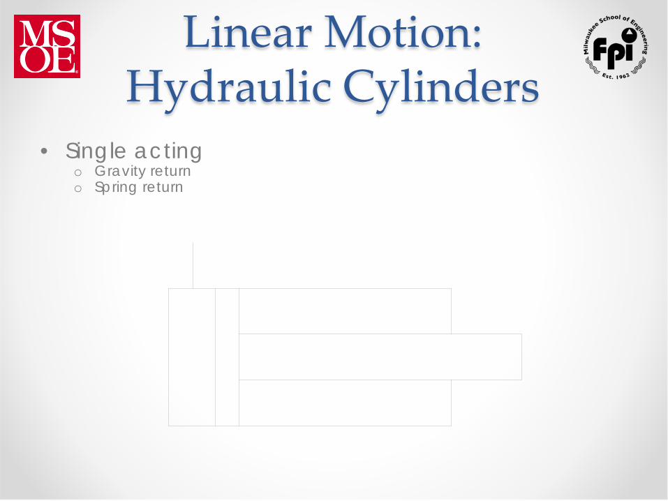
Linear Motion: Hydraulic Cylinders
• Single acting
o Gravity return o Spring return

Linear Motion: Hydraulic Cylinders
• Double acting
o Differential area o Most common configuration

Single Acting Cylinder Circuit

Linear Motion: Hydraulic Cylinders
Double rod • Same area • One rod working

Double Rod Annular areas are equal
Cylinder has equal maximum force capability and same speed in both directions.
Rotary Loads
• Hydraulic motor has continuous rotation • Rotary actuator refers to device with limited
rotation - also known as oscillating motor or torque generator.
Motor Calculations
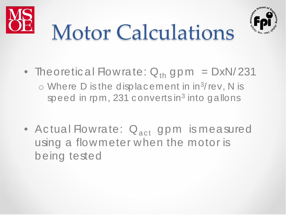
• Theoretical Flowrate: Qth gpm = DxN/231 o Where D is the displacement in in3/rev, N is
speed in rpm, 231 converts in3 into gallons
• Actual Flowrate: Qact gpm is measured using a flowmeter when the motor is being tested

Motor Calculations
• Theoretical Torque: Tth in-lbs = DxΔP/2π o Where D is displacement in in3/rev, ΔP is
differential pressure in psid
• Actual Torque: Tact in-lbs is measured using a torque shaft when the motor is being tested

Motor Calculations
• Output Horsepower: o {(Tact in-lbs)x(N rpm)}/63025
• Input Horsepower:
o {(Qact gpm)x(ΔP psid)}/1714

Motor Efficiencies
• Volumetric Efficiency: Indicates the amount of leakage that takes place inside the motor due to manufacturing tolerances and imperfect sealing surfaces
• It is expressed as a ratio of theoretical flow to actual flow: o Ev = (Qth)/(Qact)

Motor Efficiencies
• Mechanical Efficiency: Indicates the amount of energy losses that occur for reasons other than leakage. This includes friction between mating surfaces as well as fluid turbulence
• It is expressed as a ratio of actual torque to theoretical torque: o Em = (Tact)/(Tth)

Motor Efficiencies
• Overall Efficiency: Indicates the amount of all energy losses in the motor
• It is expressed as a ratio of output horsepower to input horsepower: o Eo = (HPo)/(HPi) o Eo is also = (Ev)x(Em)

Typical Catalog Data for a Hydraulic Motor
2,000 psi
1,500 psi
1,000 psi
500 psi
0 400 800 1200 1600 20000
250
500
750
1000
1250
10 gpm 20 gpm 30 gpm
Tin.-lb
n - rpm
Displacement =
4.0 in3/revolution

Example Using Catalog Graph from Preceding Slide
• Determine the performance when the motor is receiving 20 gpm and the load dictates an operating pressure differential of 2,000 psid.
• The motor will be operating at a speed of
1,100 rpm and producing a torque of 1,200 in-lbs.

Example using catalog graph from preceding slide
Output horsepower = T x N/63025 (1,200 in-lbs x 1,100 rpm)/63025 = 20.9 HP Input horsepower = ΔP x Q/1714 (2,000 psid x 20 gpm)/1714 = 23.3 HP

Example using catalog graph from preceding slide
Theoretical speed = Q x 231/D (20 gpm x 231)/(4 in3/rev) = 1,155rpm Theoretical torque = ΔP x D/2π (2,000 psid x 4in3/rev)/2π = 1,274 in-lbs
Example using catalog graph from preceding slide
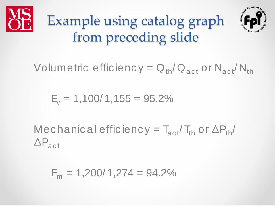
Volumetric efficiency = Qth/Qact or Nact/Nth
Ev = 1,100/1,155 = 95.2% Mechanical efficiency = Tact/Tth or ΔPth/ ΔPact
Em = 1,200/1,274 = 94.2%

Example using catalog graph from preceding slide
Overall efficiency = HPo/HPi
Eo = 20.9/23.3 = 89.7% Overall efficiency = Ev x Em
Eo = 0.952 x 0.942 = 89.7%

Motor Sizing Example • Determine the required load torque
o This includes starting torque as well as running torque o If the load has large inertia and fast acceleration, then the
starting torque could be significantly higher than the running torque
• Determine the required load speed • Select a target differential pressure
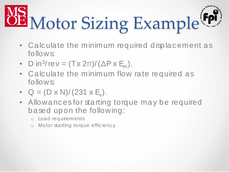
Motor Sizing Example • Calculate the minimum required displacement as
follows: • D in3/rev = (T x 2π)/(ΔP x Em). • Calculate the minimum flow rate required as
follows: • Q = (D x N)/(231 x Ev). • Allowances for starting torque may be required
based upon the following: o Load requirements o Motor starting torque efficiency

Motor Sizing Example
• Either the displacement or the available differential pressure must be increased to account for motor starting torque efficiency and load starting requirements
• On some motor designs, the starting torque at a given differential pressure can be as low as 70% of the running torque at the same differential pressure
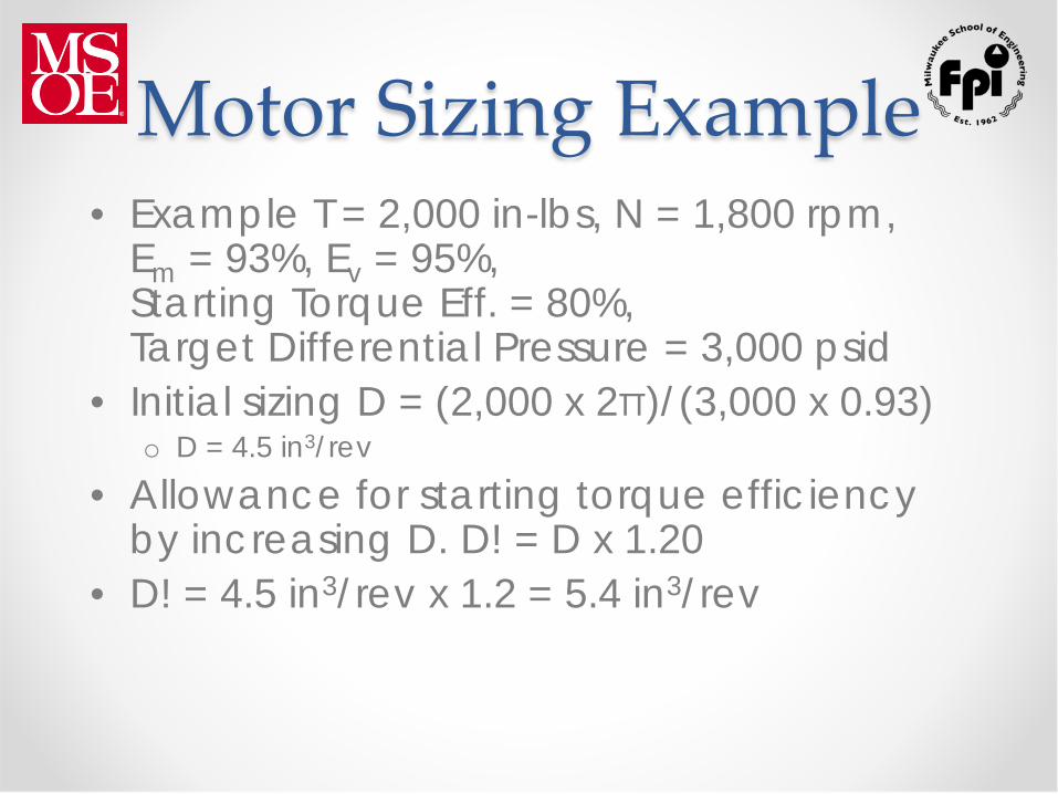
Motor Sizing Example • Example T = 2,000 in-lbs, N = 1,800 rpm,
Em = 93%, Ev = 95%, Starting Torque Eff. = 80%, Target Differential Pressure = 3,000 psid
• Initial sizing D = (2,000 x 2π)/(3,000 x 0.93) o D = 4.5 in3/rev
• Allowance for starting torque efficiency by increasing D. D! = D x 1.20
• D! = 4.5 in3/rev x 1.2 = 5.4 in3/rev

Motor Sizing Example • Allowance for starting torque efficiency
by increasing differential pressure ΔP! = ΔPtarget x 1.20 = 3,000 x 1.2 o ΔP! = 3,600 psid
• Required flowrate based upon original value of D: Q = (4.5 x 1,800)/(231 x 0.95) o Q = 36.9 gpm

Motor Sizing Example • Required flowrate based upon D!:
Q = (5.4 x 1800)/(231 x 0.95) o Q! = 44.3 gpm

Hydraulic Motor Shaft Seal
• Hydraulic motors are apt to provide an external case drain in order to use a low-pressure shaft seal for installations which require bi-directional operation or braked stopping in only one direction
• Some manufacturers have hydraulic motor designs which eliminate the case drain by using a high-pressure mechanical shaft seal

Rotary Actuators • Function
o The rotary actuator rotates an output shaft through a limited arc, which may be more or less than 360 deg
o It produces high torque at relatively low speed
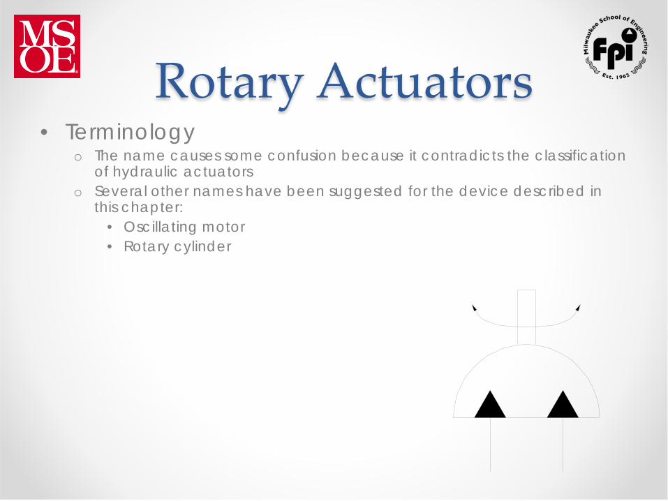
Rotary Actuators • Terminology
o The name causes some confusion because it contradicts the classification of hydraulic actuators
o Several other names have been suggested for the device described in this chapter:
• Oscillating motor • Rotary cylinder

Types of Construction • The external appearance of the vane type
has the general configuration of a hydraulic motor
• The other types look rather like a hydraulic cylinder with a shaft that rotates instead of extending
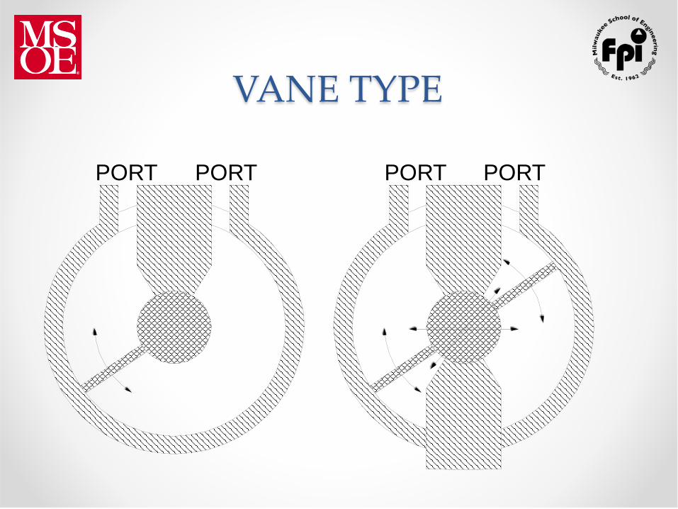
VANE TYPE
PORT PORT PORT PORT

RACK-AND-PINION

HELICAL SPLINE
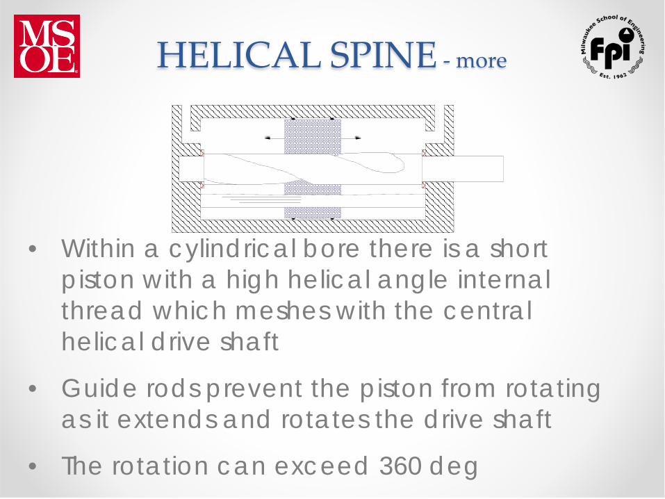
HELICAL SPINE - more
• Within a cylindrical bore there is a short piston with a high helical angle internal thread which meshes with the central helical drive shaft
• Guide rods prevent the piston from rotating as it extends and rotates the drive shaft
• The rotation can exceed 360 deg

HELICAL SPLINE - more
• This design is used where a long, slim envelope is desired
• It offers the advantage of load locking, because the helix angle is designed to resist rotation by external loads

Applications • Axes of hydraulic robots • Welding fixtures to turn over the workpiece • Indexing work tables • Clamping • Dipping the workpiece in a tank of liquid • Material mixing processes • Roll-over devices such as metal coil up-
enders

Rotary Actuator Definitions
Dv = displacement, in3/rev
F = load force, lb.
r = load radius, in.
n = rotational speed, rpm
v = load velocity, ft/sec
Q = hydraulic fluid flow rate from pump, gpm
r
n F
v

Rotary Actuator Circuit
M
Basic Hydraulic Circuits

M
Double Acting Cylinder Circuit With Tandem Center
Valve

Cylinder Circuit with Pilot Operated Check Valves
M
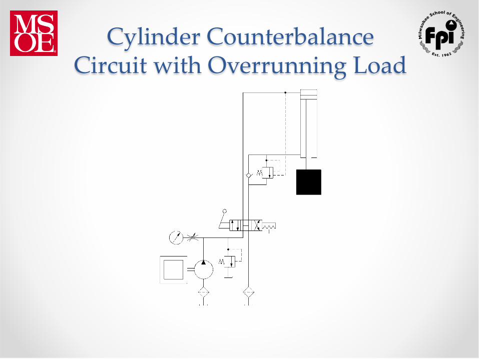
Cylinder Counterbalance Circuit with Overrunning Load
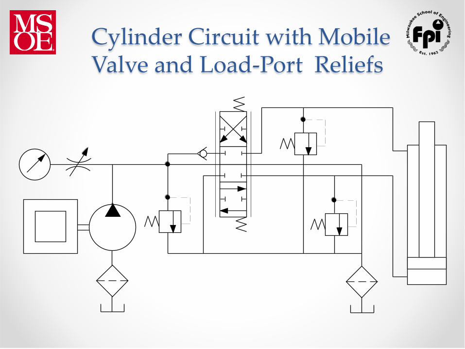
Cylinder Circuit with Mobile Valve and Load-Port Reliefs

Cylinder Circuit with Mobile Valve and Work-port Anti-Cavitation Checks

Parallel Stack Valve with Joy Stick
A B
A B
J

Cylinder Circuit with Load-Sensing Relief Valve
3000psi
100psi

M

Pressure Compensated Pump Schematic
to load

Cylinder Circuit with Load-Sensing Pump
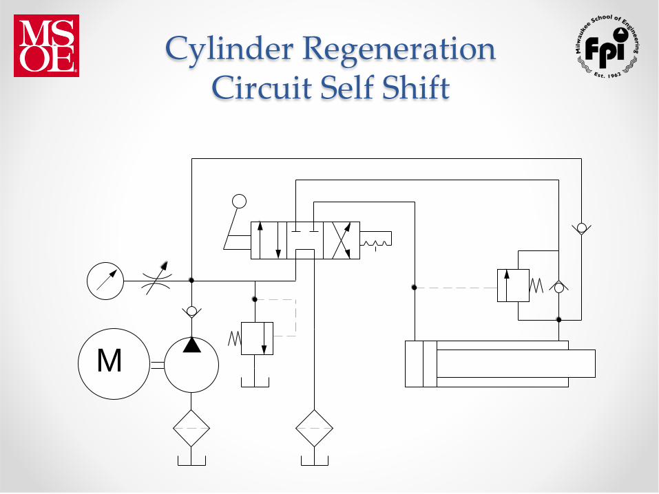
Cylinder Regeneration Circuit Self Shift
M

Cylinder Regeneration Fourth Position on Valve Spool
M

Rotary Actuator Circuit
M

Bi-Directional Motor Free Wheeling Stop
M
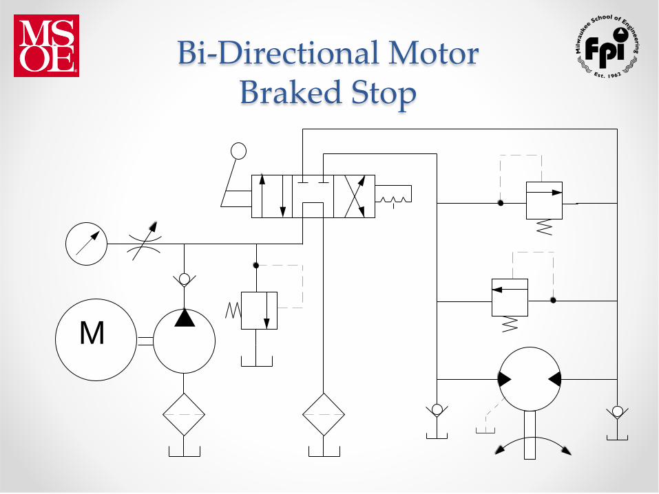
Bi-Directional Motor Braked Stop
M

Uni-Directional Motor with Brake Valve
M

Parallel Hydraulic Motors
M

Series Hydraulic Motors
M

Hydrostatic Transmission Basic Circuit Variable Pump Fixed Motor

High Low Pump Circuit
M

Accumulator Circuit
M

Multiple Actuators with Gear Type Flow Divider
M

Meter-In Flow Control
M
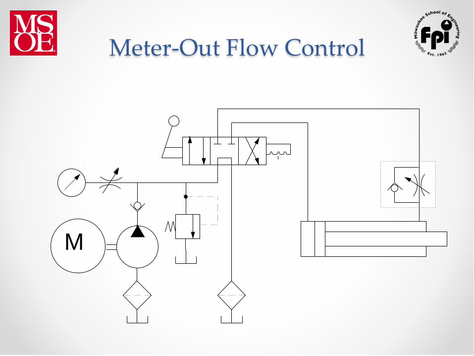
Meter-Out Flow Control
M

Multiple Actuators With Flow Divider Valve
M

Illustrations Courtesy of:
Skid Steers

Scissor Lift
Illustrations Courtesy of:

Any Questions ?
Thank You