Embed Size (px)
Citation preview
Introduction to Mechatronics
1/30/201
9
Jith
in K
Fra
nci
s,A
sst
Pro
f,R
SET
1
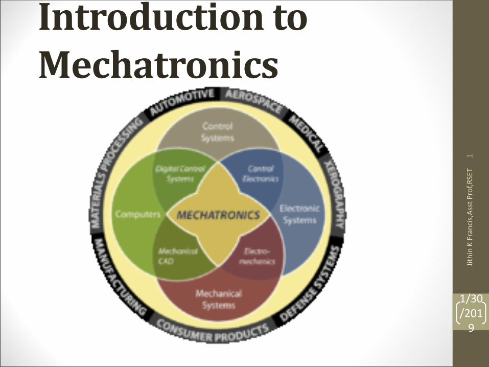
Mechatronics• Mechatronics is the synergistic combination of
mechanical and electrical engineering, computerscience, and information technology, whichincludes the use of control systems as well asnumerical methods to design products withbuilt-in intelligence.
1/30/201
9
Jith
in K
Fra
ncis
,Asst P
rof,
RS
ET
2
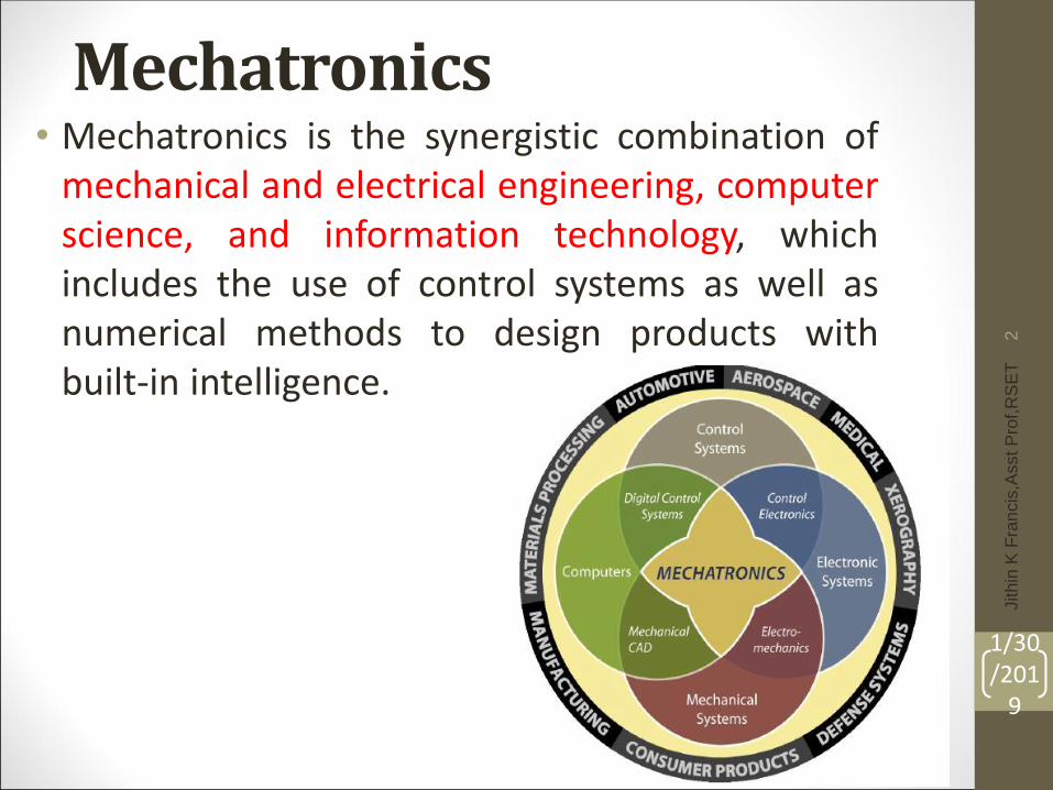
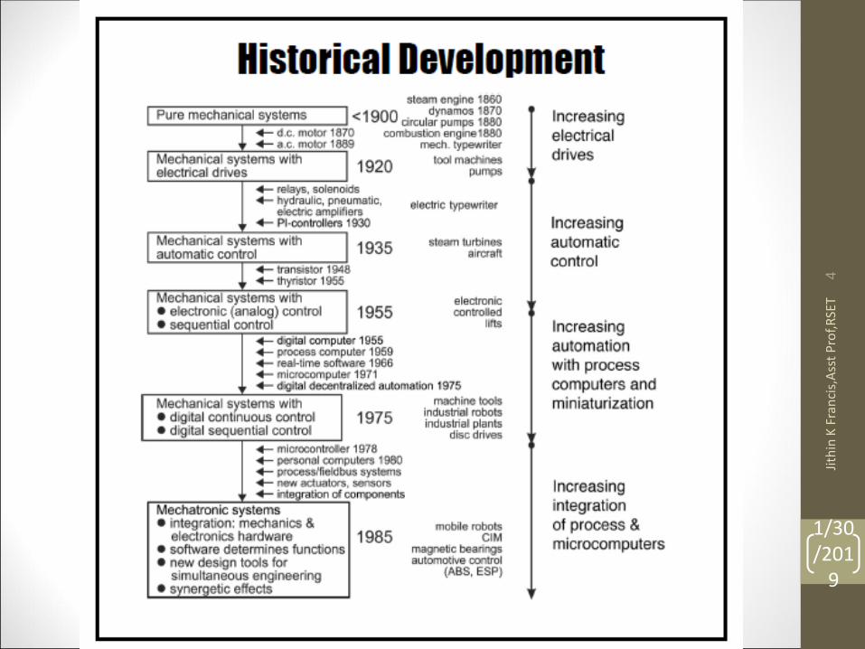
Basics of Mechatronics
Always described
as a combination
of mechanical
and electronic
devices
1/30/201
9
Jith
in K
Fra
nci
s,A
sst
Pro
f,R
SET
3
1/30/201
9
Jith
in K
Fra
nci
s,A
sst
Pro
f,R
SET
4
Examples of Mechatronics systems
Let’s look at some examples of mechatronic
systems
• Automotive Systems
• Drive by Wire
• Camless Engines
• Robotics
• Humanoids
• Telemedicine/Remote Surgery
• House Hold appliances
• Washing Machine
• Iron Box
1/30/201
9
Jith
in K
Fra
nci
s,A
sst
Pro
f,R
SET
5
Automotive Systems : Technology in today’s vehicle
• Adaptive Cruise Control
• Drive by wire
• Telematics
• Software body control
• Rain-sensing Wipers
• In-vehicle entertainment such as Small LCD display for games
• Generation II ABS
• Heads-up display
• Back-up collision sensor
• Navigation
• Tire Pressure Monitor
Technology transitions in the auto industry in the next five years:
• From Gasoline to hybrid to fuel cell and hydrogen.
• Mechanical connection to “Drive-by-wire”.
• Adoption and implementation of IT standards in the technology of the car such as surfing
in the net for navigation and other purposes.
• “On-demand” to “Always-on” vehicle connectivity to the Internet
1/30/201
9
Jith
in K
Fra
nci
s,A
sst
Pro
f,R
SET
6
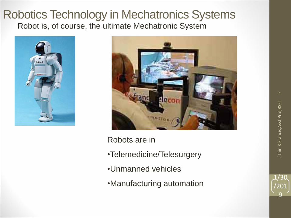
Robotics Technology in Mechatronics SystemsRobot is, of course, the ultimate Mechatronic System
Robots are in
•Telemedicine/Telesurgery
•Unmanned vehicles
•Manufacturing automation 1/30/201
9
Jith
in K
Fra
nci
s,A
sst
Pro
f,R
SET
7
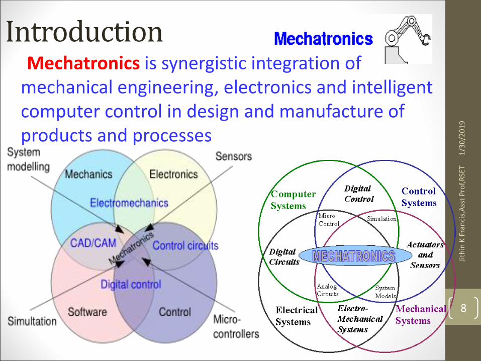
IntroductionMechatronics is synergistic integration of
mechanical engineering, electronics and intelligent computer control in design and manufacture of products and processes
1/3
0/2
01
9Ji
thin
K F
ran
cis,
Ass
t P
rof,
RSE
T
8
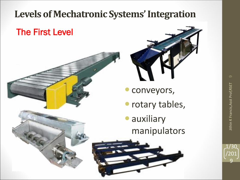
Levels of MechatronicSystems’ Integration
conveyors,
rotary tables,
auxiliary manipulators
The First Level
1/30/201
9
Jith
in K
Fra
nci
s,A
sst
Pro
f,R
SET
9
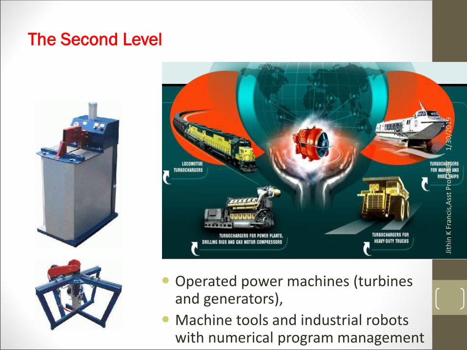
Operated power machines (turbines and generators),
Machine tools and industrial robots with numerical program management
The Second Level
1/3
0/2
01
9Ji
thin
K F
ran
cis,
Ass
t P
rof,
RSE
T
10
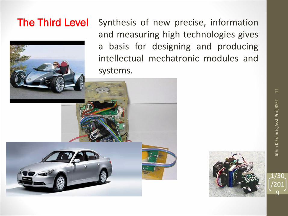
Synthesis of new precise, informationand measuring high technologies givesa basis for designing and producingintellectual mechatronic modules andsystems.
The Third Level
1/30/201
9
Jith
in K
Fra
nci
s,A
sst
Pro
f,R
SET
11
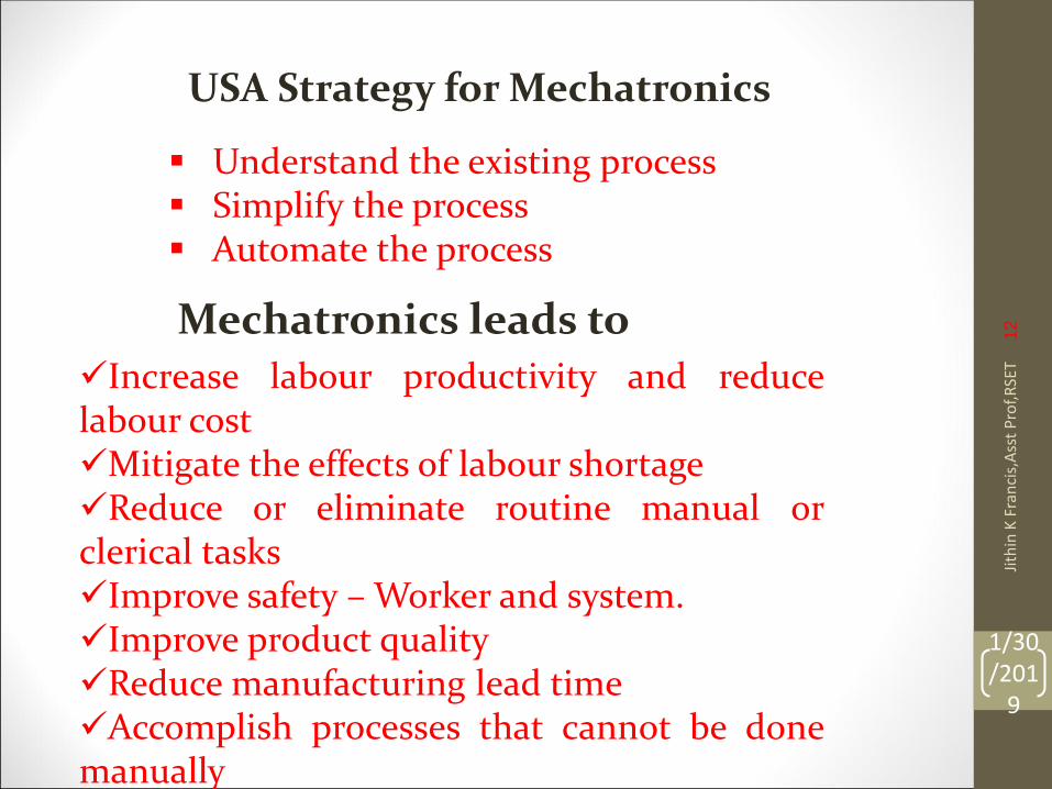
Understand the existing process Simplify the process Automate the process
USA Strategy for Mechatronics
Mechatronics leads to Increase labour productivity and reducelabour costMitigate the effects of labour shortageReduce or eliminate routine manual orclerical tasksImprove safety – Worker and system.Improve product qualityReduce manufacturing lead timeAccomplish processes that cannot be donemanually
1/30/201
9
Jith
in K
Fra
nci
s,A
sst
Pro
f,R
SET
12
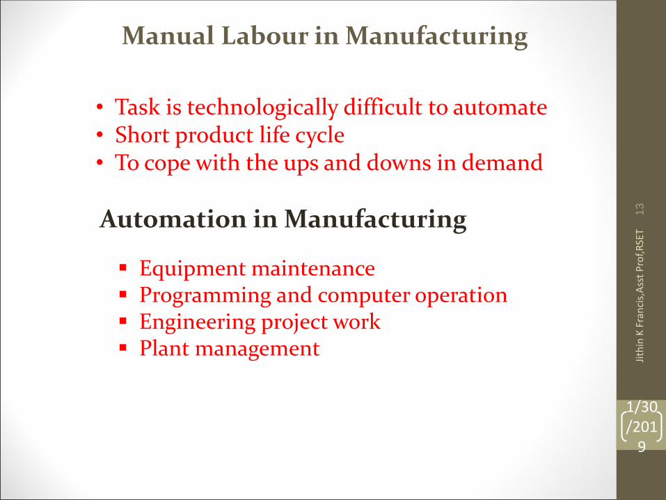
• Task is technologically difficult to automate• Short product life cycle• To cope with the ups and downs in demand
Manual Labour in Manufacturing
Automation in Manufacturing
Equipment maintenance Programming and computer operation Engineering project work Plant management
1/30/201
9
Jith
in K
Fra
nci
s,A
sst
Pro
f,R
SET
13
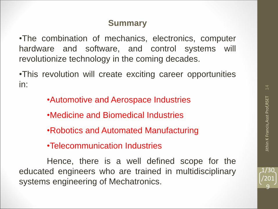
Summary
•The combination of mechanics, electronics, computer
hardware and software, and control systems will
revolutionize technology in the coming decades.
•This revolution will create exciting career opportunities
in:
•Automotive and Aerospace Industries
•Medicine and Biomedical Industries
•Robotics and Automated Manufacturing
•Telecommunication Industries
Hence, there is a well defined scope for the
educated engineers who are trained in multidisciplinary
systems engineering of Mechatronics.
1/30/201
9
Jith
in K
Fra
nci
s,A
sst
Pro
f,R
SET
14
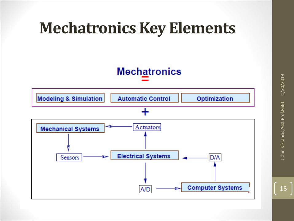
Mechatronics Key Elements
1/3
0/2
01
9Ji
thin
K F
ran
cis,
Ass
t P
rof,
RSE
T
15
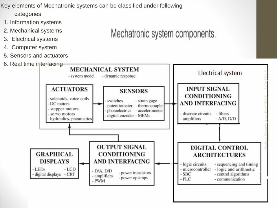
Key elements of Mechatronic systems can be classified under following
categories
1. Information systems
2. Mechanical systems
3. Electrical systems
4. Computer system
5. Sensors and actuators
6. Real time interfacing
1/3
0/2
01
9Ji
thin
K F
ran
cis,
Ass
t P
rof,
RSE
T
16
Career Paths in Mechatronics
• mechatronics is seen as a prime career path for mechanical engineers of the future;
• mechanical engineers with a mechatronics background will have a better chance of becoming managers;
• classically trained mechanical engineers will run the risk of being left out of the interesting work.
1/3
0/2
01
9Ji
thin
K F
ran
cis,
Ass
t P
rof,
RSE
T
17
DEFINITIONS OF MECHATRONICS• “Integration of electronics, control
engineering, and mechanical engineering.”
• “Synergistic integration of mechanical engineering with electronics and intelligent computer control in the design and manufacturing of industrial products and processes.”
1/3
0/2
01
9Ji
thin
K F
ran
cis,
Ass
t P
rof,
RSE
T
18
DEFINITIONS OF MECHATRONICS• “Synergistic use of precision engineering, control
theory, computer science, and sensor and actuator technology to design improved products and processes.”
• “Methodology used for the optimal design of electromechanical products.”
• “Field of study involving the analysis, design, synthesis, and selection of systems that combine electronics and mechanical components with modern controls and Microprocessors.”
1/3
0/2
01
9Ji
thin
K F
ran
cis,
Ass
t P
rof,
RSE
T
19
Mechatronics: Working Definition
• Mechatronics is the synergistic integration ofsensors, actuators, signal conditioning, powerelectronics, decision and control algorithms,and computer hardware and software tomanage complexity, uncertainty, andcommunication in engineered systems.
1/3
0/2
01
9Ji
thin
K F
ran
cis,
Ass
t P
rof,
RSE
T
20
DISCIPLINARY FOUNDATIONS OF MECHATRONICS
• • Mechanical Engineering
• • Electrical Engineering
• • Computer Engineering
• • Computer/Information Systems
1/3
0/2
01
9Ji
thin
K F
ran
cis,
Ass
t P
rof,
RSE
T
21
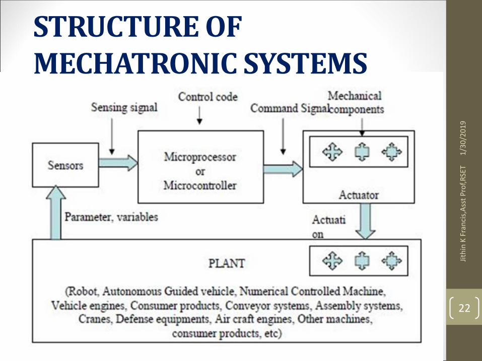
STRUCTURE OF MECHATRONIC SYSTEMS
1/3
0/2
01
9Ji
thin
K F
ran
cis,
Ass
t P
rof,
RSE
T
22
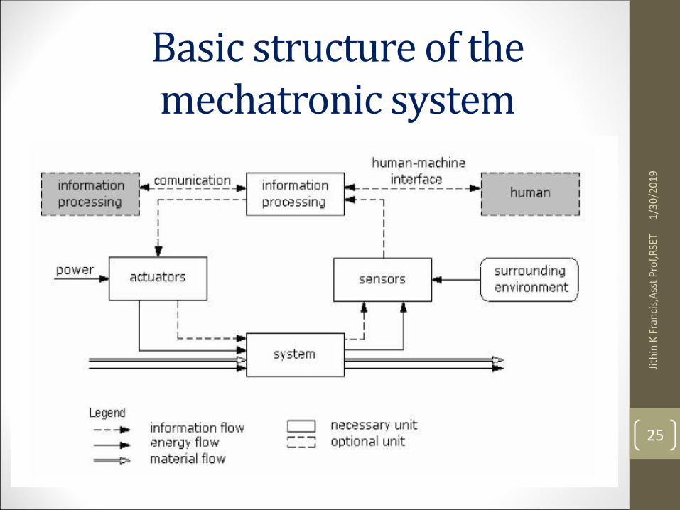
Basic structure of mechatronics• Basic structure
• A basic structure of the mechatronic system is created by a system, sensors, actuators and devices for information processing. The surrounding environment, in which the mechatronic system operates.
• The system has usually a mechanical, electromechanical or hydraulic structure or it is a combination of these structures.
• The task of sensors is to determine a chosen variable value of the system.
1/3
0/2
01
9Ji
thin
K F
ran
cis,
Ass
t P
rof,
RSE
T
23
• The sensors can be physically represented by the measured values or software sensors so called “observers”.
• The sensors supply input variables for the information processing, at present usually digital, i.e. discrete in terms of values and time.
• The information processing is usually done by a microprocessor. The information processing determines actions needed to affect appropriately the state variables of the system. An implementation of the actions is directly in the system by the actuators.
1/3
0/2
01
9Ji
thin
K F
ran
cis,
Ass
t P
rof,
RSE
T
24
Basic structure of the mechatronic system
1/3
0/2
01
9Ji
thin
K F
ran
cis,
Ass
t P
rof,
RSE
T
25
USEFUL PROPERTIES OF MECHATRONICS
1) An innovative potential of technology and their functional and spatial integration.
2) Dynamical development of electronic and software-technical components and their systematic integration into a previously purely mechanical product.
3) The dynamic property brings about a number of opportunities, their integration can be used to create mechatronic products.
4) Mechatronics is a new combination of known production technologies that gives rise to the second source of opportunities.ex conversion of conventional lathe to automatic.
1/3
0/2
01
9Ji
thin
K F
ran
cis,
Ass
t P
rof,
RSE
T
26
USEFUL PROPERTIES OF MECHATRONICS
1) Technical progress allows incorporation of electronic components and software to a purely mechanical or electro technical products.
2) Possibility of modularization of a product which means to form a modular structure of product in which connections between modules are less different than relations inside the modules.
3) Interfacing between modules is created so that compatibility is ensured even if innovation dynamics of components differ, e.g. hardware components of different product generations or software update of unchanged hardware, etc.
1/3
0/2
01
9Ji
thin
K F
ran
cis,
Ass
t P
rof,
RSE
T
27
To define mechatronics with single sentence
• “Mechatronics is the synergistic integration of mechanical engineering with electronics and electrical with intelligent computer control in the design and manufacture of industrial products, processes and operations”.
1/3
0/2
01
9Ji
thin
K F
ran
cis,
Ass
t P
rof,
RSE
T
28
SYSTEM
• The mechatronic system is made of several systems like measurement system, drive and actuation system, control system, microprocessor system, and computer system. The characteristics of each system are
• System: A system can be thought of which has an input and an output and where we do not consider what input but only the relationship between the output and input.
1/3
0/2
01
9Ji
thin
K F
ran
cis,
Ass
t P
rof,
RSE
T
29
SYSTEM
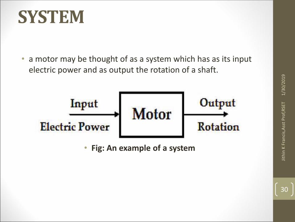
• a motor may be thought of as a system which has as its input electric power and as output the rotation of a shaft.
• Fig: An example of a system
1/3
0/2
01
9Ji
thin
K F
ran
cis,
Ass
t P
rof,
RSE
T
30
Measurement System
• Measurement System: A measurement system is a system which is used for making measurements. It has as its input the quantity being measured and its output the value of that quantity. For example, a temperature measurement system, i.e. a thermometer, has an input of temperature and an output of a number on a scale
1/3
0/2
01
9Ji
thin
K F
ran
cis,
Ass
t P
rof,
RSE
T
31
• The system can be purely mechanical, electrical or electronic requiring compatible inputs. But the mechatronic system is the combination of these systems.
1/3
0/2
01
9Ji
thin
K F
ran
cis,
Ass
t P
rof,
RSE
T
32
Control System:
AIR
CONDITONER
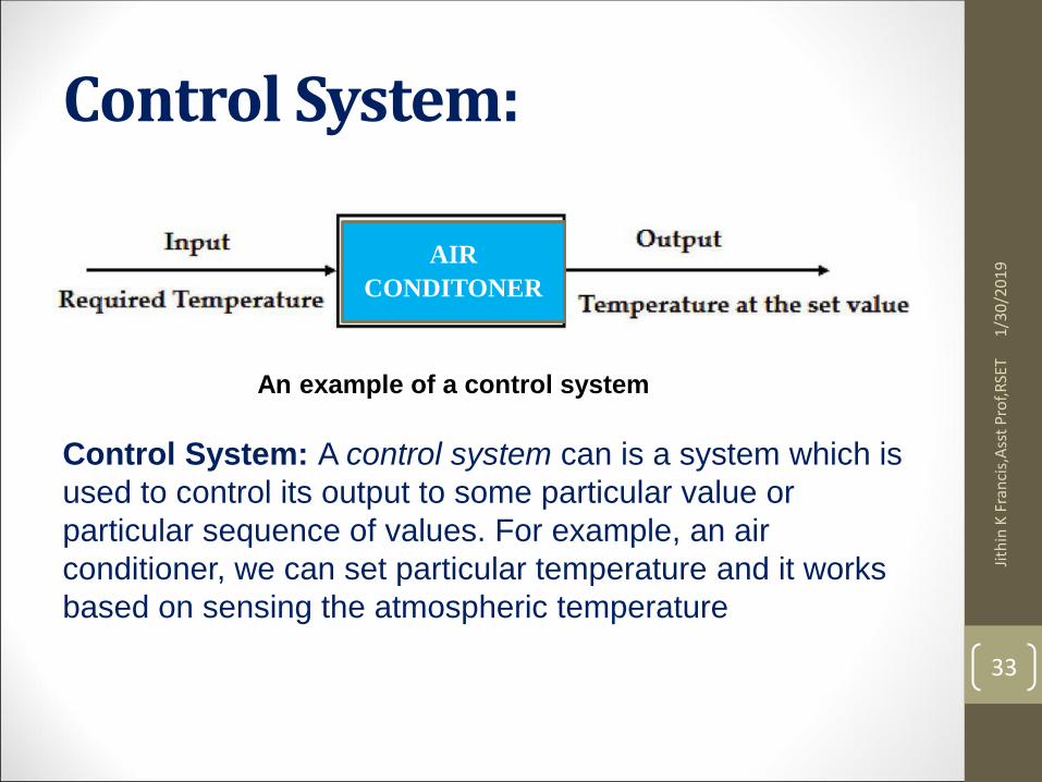
An example of a control system
Control System: A control system can is a system which is
used to control its output to some particular value or
particular sequence of values. For example, an air
conditioner, we can set particular temperature and it works
based on sensing the atmospheric temperature
1/3
0/2
01
9Ji
thin
K F
ran
cis,
Ass
t P
rof,
RSE
T
33
MEASUREMENT SYSTEMS
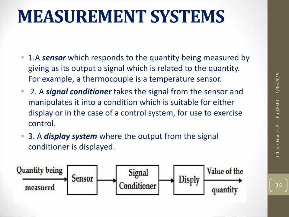
• 1.A sensor which responds to the quantity being measured by giving as its output a signal which is related to the quantity. For example, a thermocouple is a temperature sensor.
• 2. A signal conditioner takes the signal from the sensor and manipulates it into a condition which is suitable for either display or in the case of a control system, for use to exercise control.
• 3. A display system where the output from the signal conditioner is displayed.
1/3
0/2
01
9Ji
thin
K F
ran
cis,
Ass
t P
rof,
RSE
T
34
Control systems may be classified as;
• Open loop control system.
• Closed loop or feedback control system. 1/3
0/2
01
9Ji
thin
K F
ran
cis,
Ass
t P
rof,
RSE
T
35
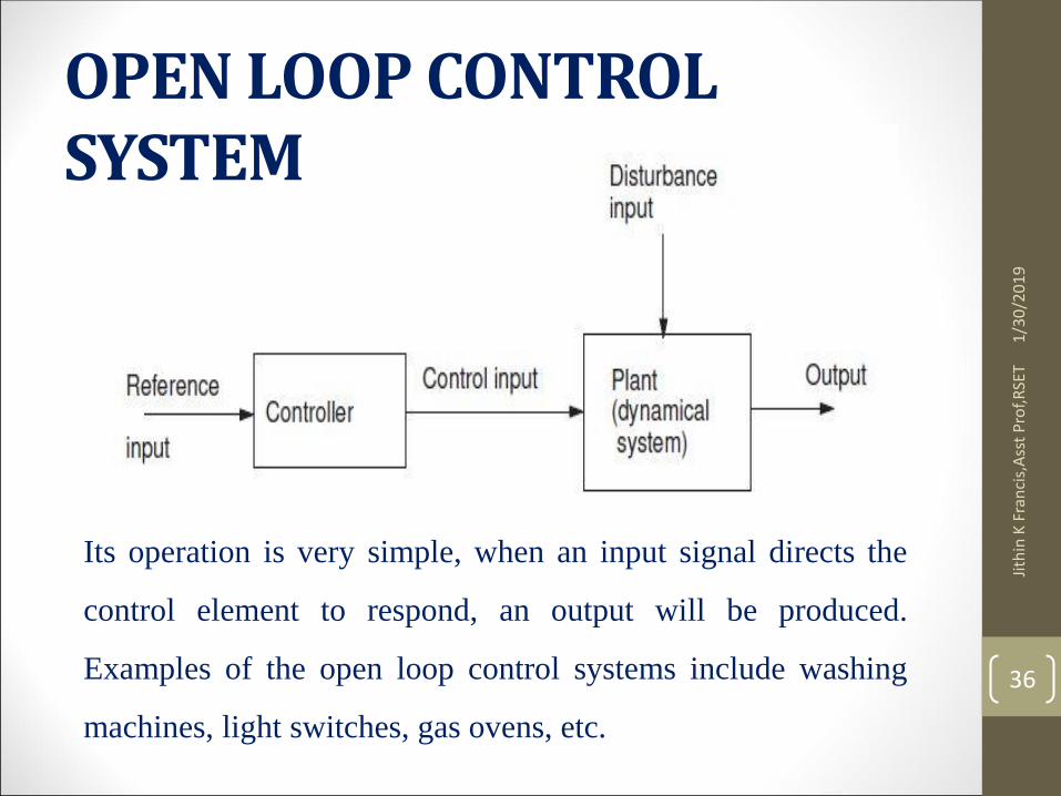
OPEN LOOP CONTROL SYSTEM
Its operation is very simple, when an input signal directs the
control element to respond, an output will be produced.
Examples of the open loop control systems include washing
machines, light switches, gas ovens, etc.
1/3
0/2
01
9Ji
thin
K F
ran
cis,
Ass
t P
rof,
RSE
T
36
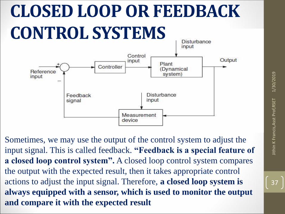
CLOSED LOOP OR FEEDBACK CONTROL SYSTEMS
Sometimes, we may use the output of the control system to adjust the
input signal. This is called feedback. “Feedback is a special feature of
a closed loop control system”. A closed loop control system compares
the output with the expected result, then it takes appropriate control
actions to adjust the input signal. Therefore, a closed loop system is
always equipped with a sensor, which is used to monitor the output
and compare it with the expected result
1/3
0/2
01
9Ji
thin
K F
ran
cis,
Ass
t P
rof,
RSE
T
37
Jith
in K
Fra
nci
s,A
sst
Pro
f,RSE
T
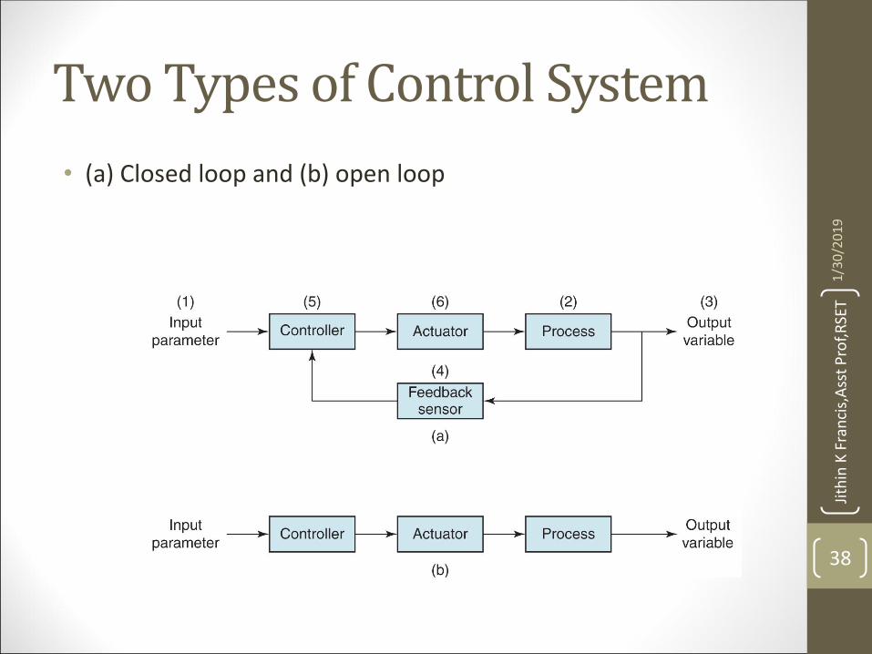
Two Types of Control System
• (a) Closed loop and (b) open loop
1/3
0/2
01
9
38
Jith
in K
Fra
nci
s,A
sst
Pro
f,RSE
T
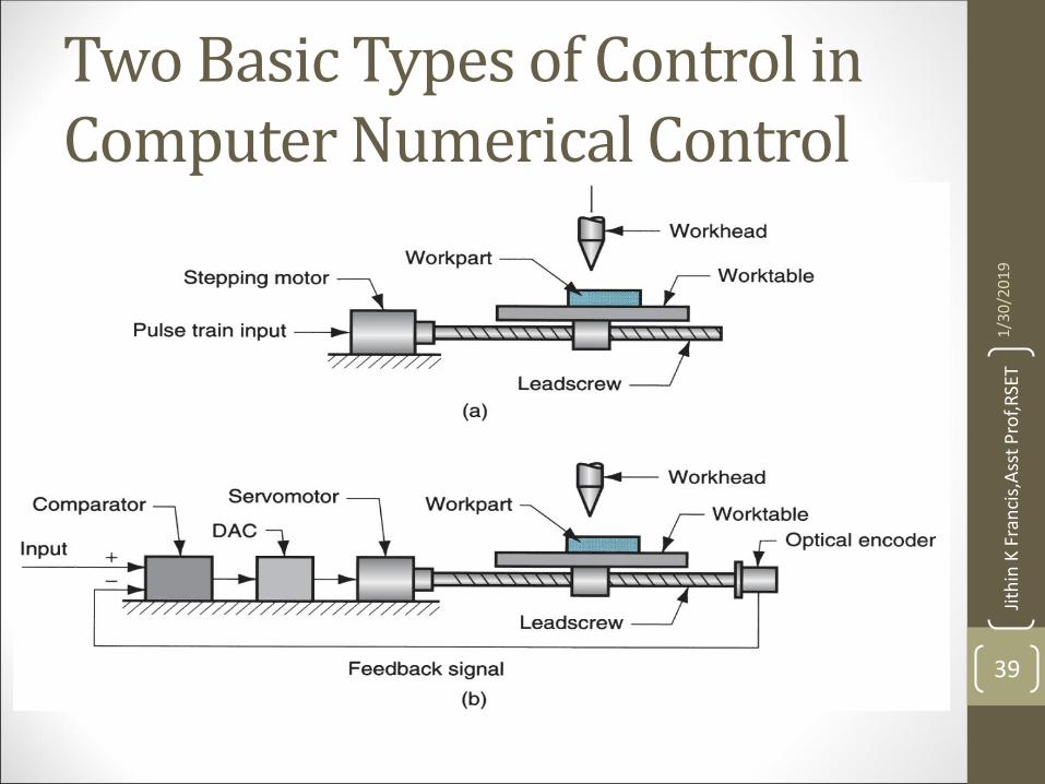
Two Basic Types of Control in Computer Numerical Control
1/3
0/2
01
9
39
OPEN LOOP SYSTEM: ADVANTAGES:
• Simplicity and stability: they are simpler in their layout and hence are economical and stable too due to their simplicity.
• Construction: Since these are having a simple layout so are easier to construct.
1/3
0/2
01
9Ji
thin
K F
ran
cis,
Ass
t P
rof,
RSE
T
40
OPEN LOOP SYSTEM: DISADVANTAGES:
• Accuracy and Reliability: since these systems do not have a feedback mechanism, so they are very inaccurate in terms of result output and hence they are unreliable too.
• Due to the absence of a feedback mechanism, they are unable to remove the disturbances occurring from external sources.
1/3
0/2
01
9Ji
thin
K F
ran
cis,
Ass
t P
rof,
RSE
T
41
CLOSED LOOP SYSTEM: ADVANTAGES:
• Accuracy: They are more accurate than open loop system due to their complex construction. They are equally accurate and are not disturbed in the presence of non-linearities.
• Noise reduction ability: Since they are composed of a feedback mechanism, so they clear out the errors between input and output signals, and hence remain unaffected to the external noise sources.
1/3
0/2
01
9Ji
thin
K F
ran
cis,
Ass
t P
rof,
RSE
T
42
CLOSED LOOP SYSTEM:DISADVANTAGES:
• Construction: They are relatively more complex in construction and hence it adds up to the cost making it costlier than open loop system.
• Since it consists of feedback loop, it may create oscillatory response of the system and it also reduces the overall gain of the system.
• Stability: It is less stable than open loop system but this disadvantage can be striked off since we can make the sensitivity of the system very small so as to make the system as stable as possible.
1/3
0/2
01
9Ji
thin
K F
ran
cis,
Ass
t P
rof,
RSE
T
43
ADVANTAGES AND DISADVANTAGES OF MECHATRONCIS
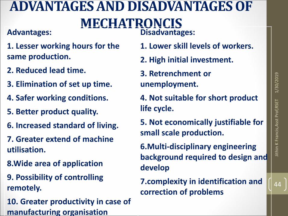
Advantages:
1. Lesser working hours for the same production.
2. Reduced lead time.
3. Elimination of set up time.
4. Safer working conditions.
5. Better product quality.
6. Increased standard of living.
7. Greater extend of machine utilisation.
8.Wide area of application
9. Possibility of controlling remotely.
10. Greater productivity in case of manufacturing organisation
Disadvantages:
1. Lower skill levels of workers.
2. High initial investment.
3. Retrenchment or unemployment.
4. Not suitable for short product life cycle.
5. Not economically justifiable for small scale production.
6.Multi-disciplinary engineering background required to design and develop
7.complexity in identification and correction of problems
1/3
0/2
01
9Ji
thin
K F
ran
cis,
Ass
t P
rof,
RSE
T
44
Sensor/transducers specifications and characteristics
• Mechatronics design engineer must know the capability and
characteristics of a transducer or measurement system to
properly assess its performance. There are a number of
performance related parameters of a transducer or
measurement system. These parameters are called as sensor
specifications.
• Sensor specifications inform the user to the about deviations
from the ideal behavior of the sensors45
Jith
in K
Fra
nci
s,A
sst
Pro
f,R
SET
1/3
0/2
01
9
Sensor/transducers specifications and characteristics • 1. Range
• The range of a sensor indicates the limits between which the input can vary. For example, a thermocouple for the measurement of temperature might have a range of 25-225 °C.
• 2. Span
• The span is difference between the maximum and minimum values of the input. Thus, the above-mentioned thermocouple will have a span of 200 °C.
• 3. Error
• Error is the difference between the result of the measurement and the true value of the quantity being measured. A sensor might give a displacement reading of 29.8 mm, when the actual displacement had been 30 mm, then the error is –0.2 mm. 46
Jith
in K
Fra
nci
s,A
sst
Pro
f,R
SET
1/3
0/2
01
9
Sensor/transducers specifications and characteristics • 4. Accuracy
• The accuracy defines the closeness of the agreement between the actual measurement result and a true value of the measurand. It is often expressed as a percentage of the full range output or full–scale deflection.
• 5. Sensitivity
• Sensitivity of a sensor is defined as the ratio of change in output value of a sensor to the per unit change in input value that causes the output change. For example, a general purpose thermocouple may have a sensitivity of 41 µV/°C.
47
Jith
in K
Fra
nci
s,A
sst
Pro
f,R
SET
1/3
0/2
01
9
Sensor/transducers specifications and characteristics
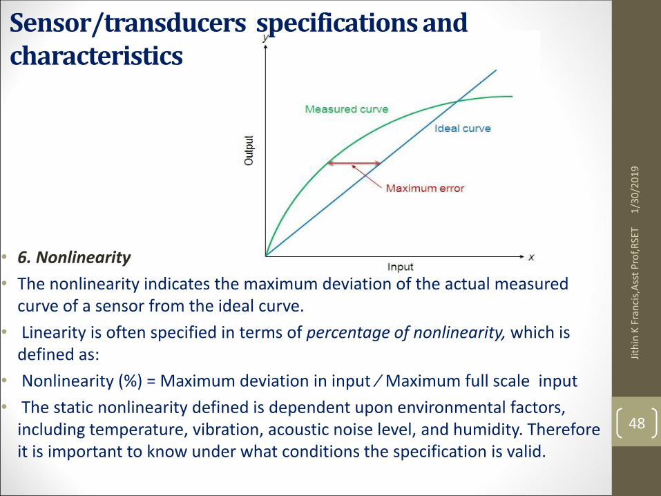
• 6. Nonlinearity
• The nonlinearity indicates the maximum deviation of the actual measured curve of a sensor from the ideal curve.
• Linearity is often specified in terms of percentage of nonlinearity, which is defined as:
• Nonlinearity (%) = Maximum deviation in input ⁄ Maximum full scale input
• The static nonlinearity defined is dependent upon environmental factors, including temperature, vibration, acoustic noise level, and humidity. Therefore it is important to know under what conditions the specification is valid.
48
Jith
in K
Fra
nci
s,A
sst
Pro
f,R
SET
1/3
0/2
01
9
Sensor/transducers specifications and characteristics
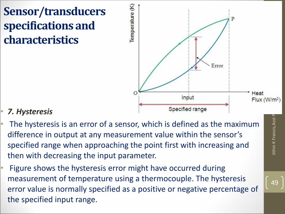
• 7. Hysteresis
• The hysteresis is an error of a sensor, which is defined as the maximum difference in output at any measurement value within the sensor’s specified range when approaching the point first with increasing and then with decreasing the input parameter.
• Figure shows the hysteresis error might have occurred during measurement of temperature using a thermocouple. The hysteresis error value is normally specified as a positive or negative percentage of the specified input range.
49
Jith
in K
Fra
nci
s,A
sst
Pro
f,R
SET
1/3
0/2
01
9
Sensor/transducers specifications and characteristics • 8. Resolution
• Resolution is the smallest detectable incremental change of input parameter that can be detected in the output signal. Resolution can be expressed either as a proportion of the full-scale reading or in absolute terms.
• For example, if a LVDT sensor measures a displacement up to 20 mm and it provides an output as a number between 1 and 100 then the resolution of the sensor device is 0.2 mm.
• 9. Stability
• Stability is the ability of a sensor device to give same output when used to measure a constant input over a period of time.
• 10. Dead band/time
• The dead band or dead space of a transducer is the range of input values for which there is no output. The dead time of a sensor device is the time duration from the application of an input until the output begins to respond or change.
50
Jith
in K
Fra
nci
s,A
sst
Pro
f,R
SET
1/3
0/2
01
9
Sensor/transducers specifications and characteristics • 11. Repeatability
• It specifies the ability of a sensor to give same output for repeated applications of same input value. It is usually expressed as a percentage of the full range output:
• Repeatability = (maximum – minimum values given) X 100 ⁄ full range
• 12. Response time
• Response time describes the speed of change in the output on a step-wise change of the measurand. It is always specified with an indication of input step and the output range for which the response time is defined.
51
Jith
in K
Fra
nci
s,A
sst
Pro
f,R
SET
1/3
0/2
01
9