Embed Size (px)
Citation preview
Designing Connections to HSSIntroduction to Moment and Truss Connections
presented by
Brad Fletcher, [email protected]
Introduction HSS General Overview Types of HSS Connections Truss Connections Moment Connections
Topics
Brad Fletcher, S.E., is a structural engineer at Atlas Tube. In this role, Brad leverages his 20 years of experience in engineering design and the steel industry to provide technical expertise on the use of steel hollow structural sections (HSS) and pipe piling products to design engineers, detailers, fabricators and architects.
A registered structural engineer in the state of Illinois, Brad has held senior positions at leading architecture and engineering firms, Skidmore, Owings & Merrill; Sargent & Lundy; and Halvorson and Partners. Brad has contributed to notable projects, including the Guggenheim Museum in Spain and the Elysian Hotel. For the past six and a half years, most recently while working at Tata Steel (formerly known as Corus), Brad has focused his efforts on serving as a liaison between structural designers and the steel industry.
Brad holds a Bachelor of Science and a Master of Science in civil engineering (BSCE, MSCE) from Purdue University. He is active in many industry groups, including the American Institute of Steel Construction (AISC), the Structural Engineers Association of Illinois (SEAOI) and ASTM International. As chairman of the HSS Marketing Committee within the AISC, Brad upholds the institute’s mission to promote the usage and understanding of steel and HSS. Brad is also on the Board of Governors for the Steel Structures Education Foundation (SSEF) in Canada and the S16 Technical Committee for the Canadian Standards Association (CSA).
About the Speaker
Corporate Overview
4
Largest size range in North America• 1”–16” square, up to 5/8” wall (larger sizes listed on CISC website)• 1.25” – 20” round, up to 5/8” wall• Now offering Jumbo HSS
Shortest rolling cycle in the industry• 2 – 3 weeks for common sizes
Able to roll custom lengths to minimize cost and waste• Rolled lengths over 100 ft.
Metallurgists and Structural Engineer on staff to assist with technical and product questions
Products stocked by service centers across North America
CIDECT Member
Four production facilities in North America
Atlas Tube – Market Leader
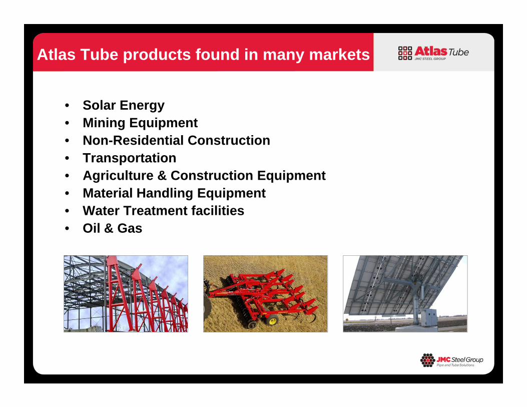
• Solar Energy • Mining Equipment• Non-Residential Construction• Transportation• Agriculture & Construction Equipment• Material Handling Equipment• Water Treatment facilities• Oil & Gas
Atlas Tube products found in many markets

Introduction HSS General Overview Types of HSS Connections Truss Connections Moment Connections
Topics
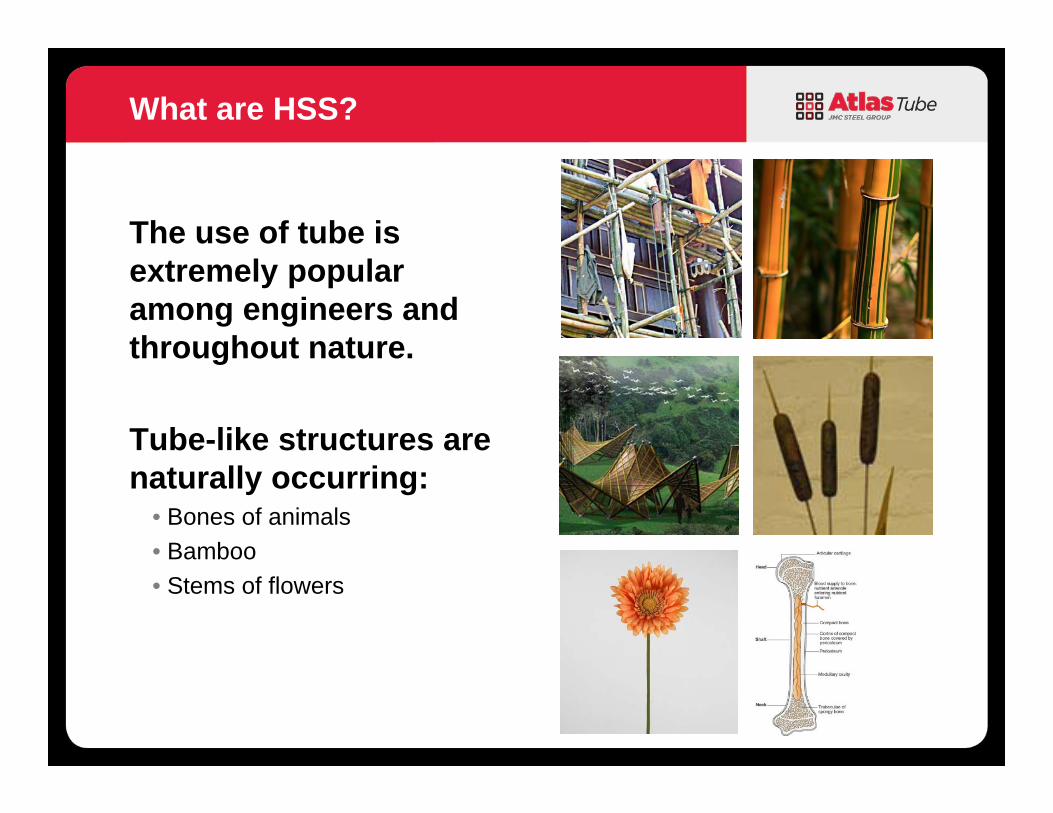
The use of tube is extremely popular among engineers and throughout nature.
Tube-like structures are naturally occurring:
• Bones of animals• Bamboo• Stems of flowers
What are HSS?
9
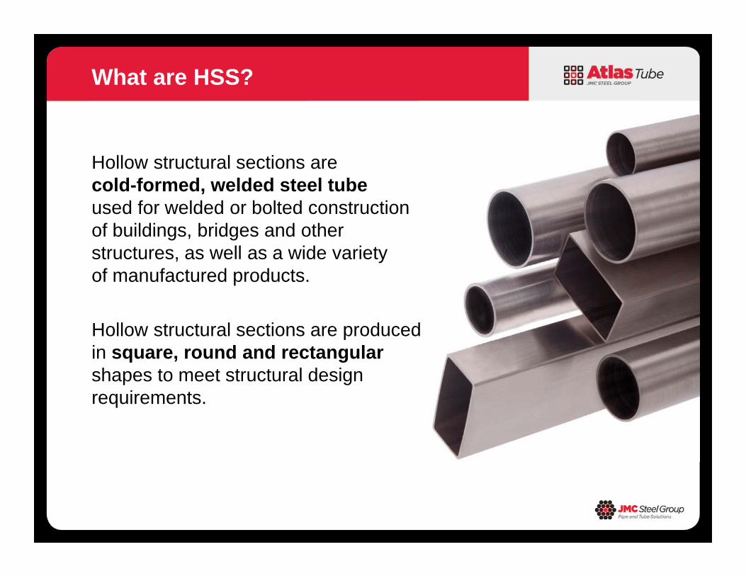
What are HSS?
Hollow structural sections are cold-formed, welded steel tube used for welded or bolted construction of buildings, bridges and other structures, as well as a wide variety of manufactured products.
Hollow structural sections are produced in square, round and rectangular shapes to meet structural design requirements.
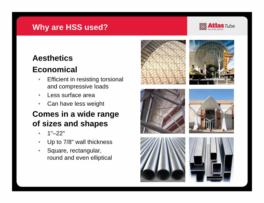
Aesthetics Economical
• Efficient in resisting torsional and compressive loads
• Less surface area• Can have less weight
Comes in a wide range of sizes and shapes
• 1"–22"• Up to 7/8" wall thickness• Square, rectangular,
round and even elliptical
Why are HSS used?
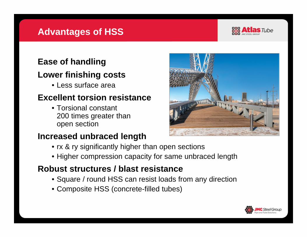
Ease of handlingLower finishing costs
• Less surface area
Excellent torsion resistance• Torsional constant
200 times greater than open section
Increased unbraced length• rx & ry significantly higher than open sections• Higher compression capacity for same unbraced length
Robust structures / blast resistance• Square / round HSS can resist loads from any direction• Composite HSS (concrete-filled tubes)
Advantages of HSS
Introduction HSS General Overview Types of HSS Connections Truss Connections Moment Connections
Topics
Connection Design for HSS• They are too hard• They are too expensive• There are not enough resources• EOR does not design connections
Challenges
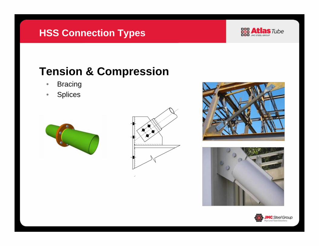
Tension & Compression• Bracing• Splices
HSS Connection Types
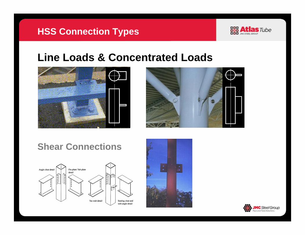
Line Loads & Concentrated Loads
HSS Connection Types
Shear Connections
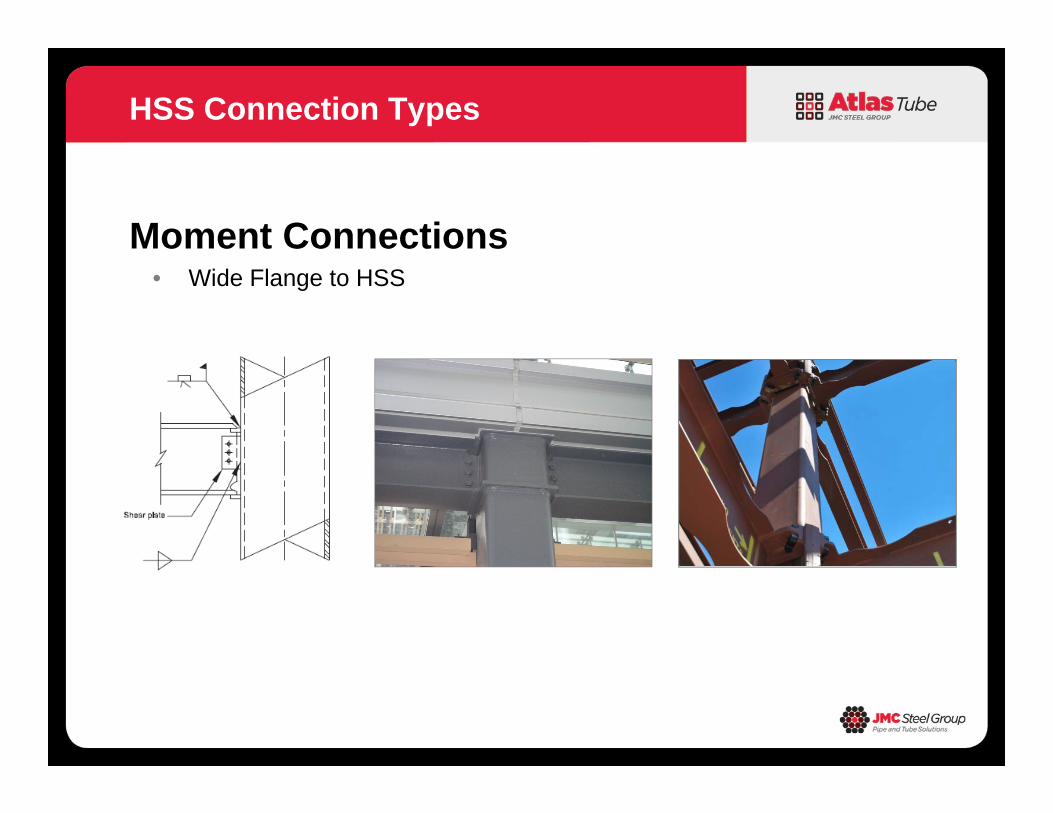
Moment Connections• Wide Flange to HSS
HSS Connection Types
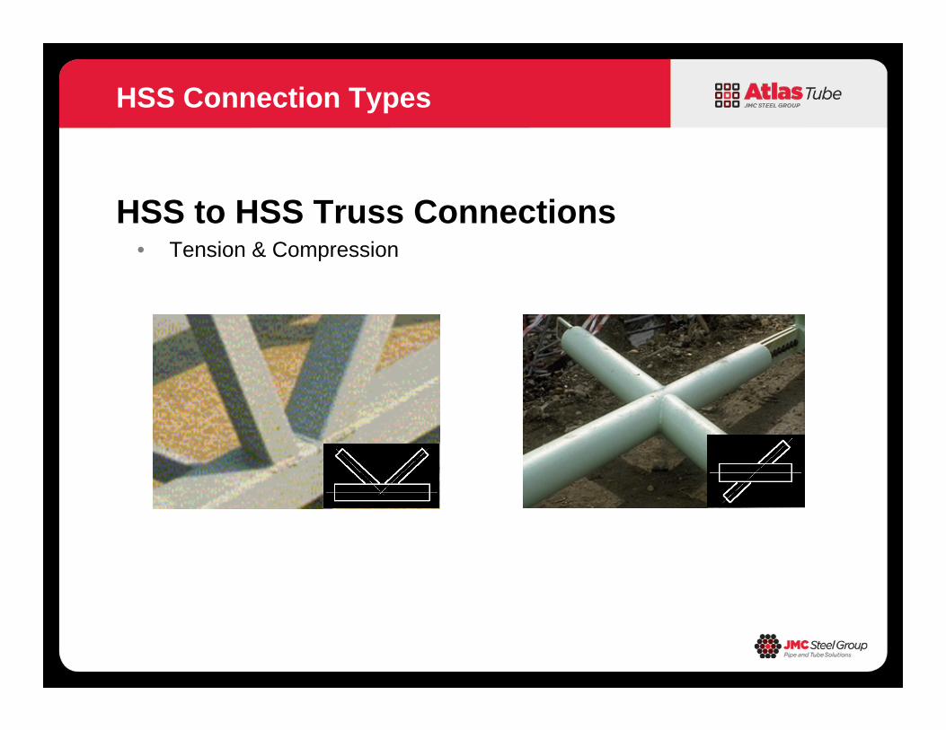
HSS to HSS Truss Connections• Tension & Compression
HSS Connection Types
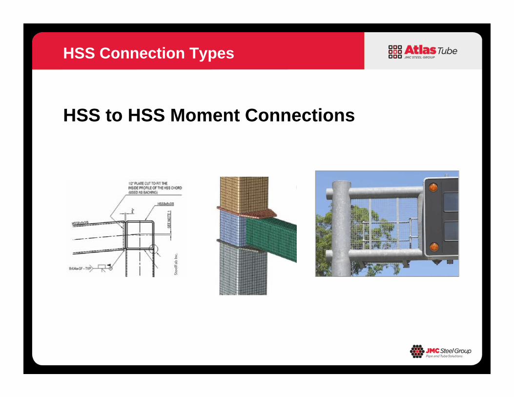
HSS to HSS Moment Connections
HSS Connection Types
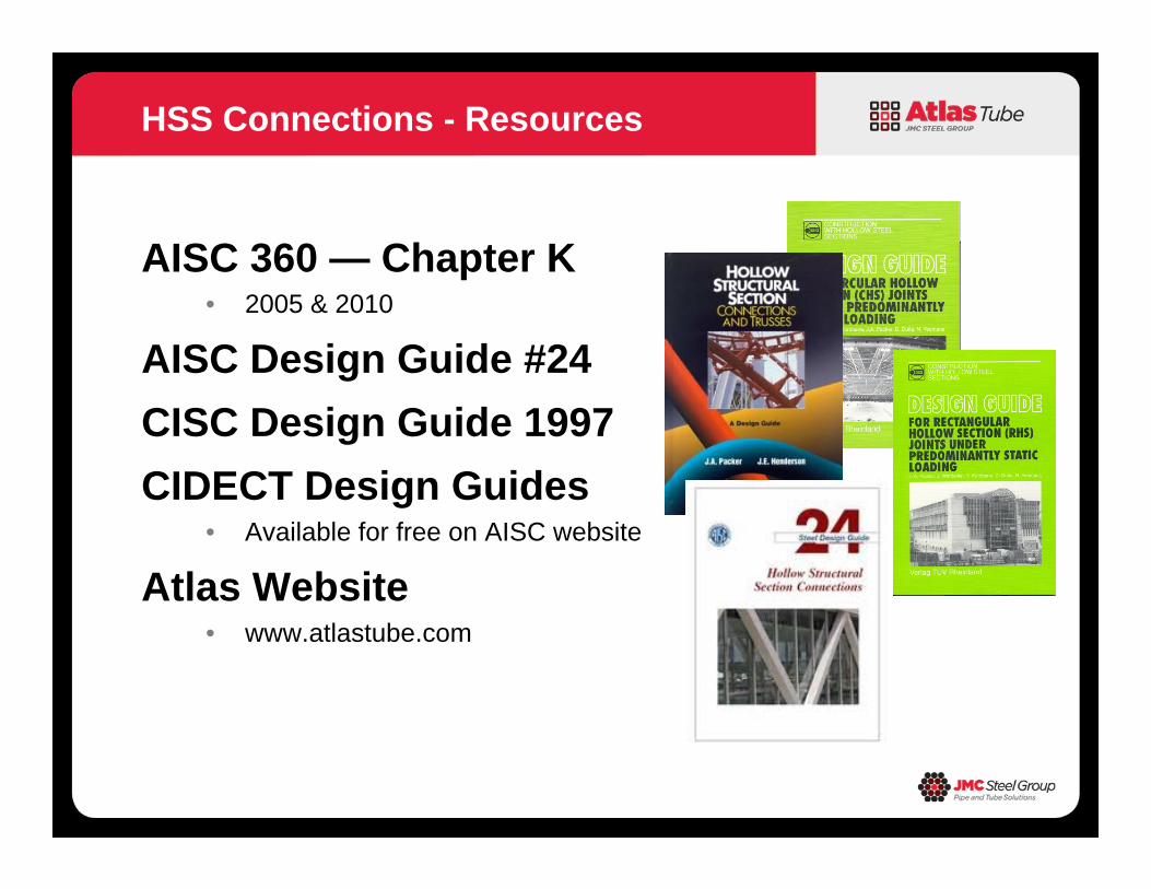
AISC 360 — Chapter K• 2005 & 2010
AISC Design Guide #24CISC Design Guide 1997CIDECT Design Guides
• Available for free on AISC website
Atlas Website• www.atlastube.com
HSS Connections - Resources
International Institute of Welding (IIW)• Subcomission XV-E published Design Recommendations on Static
Strength of Tubular Joints– 1st Edition (IIW, 1981)– 2nd Edition (IIW, 1989)– 3rd Edition (IIW, 2009)
CIDECT (International Committee for the Development and Study of TubularStructures)
• An international association of HSS and pipe manufacturersdedicated to expanding knowledge of tubular sections throughresearch and studies
– 1st ed. Design Guides based on IIW, 1989– 2nd ed. Design Guides 1 & 3 based on IIW, 2009
HSS Connections – Design Recommendations
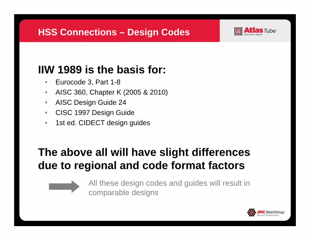
IIW 1989 is the basis for:• Eurocode 3, Part 1-8• AISC 360, Chapter K (2005 & 2010)• AISC Design Guide 24• CISC 1997 Design Guide• 1st ed. CIDECT design guides
The above all will have slight differences due to regional and code format factors
HSS Connections – Design Codes
All these design codes and guides will result in comparable designs

HSS Connections
• Its important to note that local strength of HSS members is an integral part of HSS connection design.
• Understanding these local strength issues is importantto member selection.
• Proper member selection by the EOR will have an effect on HSS connection design
• Reinforcing of connections is difficult and expensive and usually not an option due to architectural or fabrication restraints
• Even if EOR is not doing final connection design, some checks need to be done to ensure proper joint strength.
• Be sure to give good load information to the party responsible for final connection design.
The joint strength is determined by the selected chord and bracing member sizes, grades and geometry
These are decided by the
Joint Design Considerations
DESIGNER
Introduction HSS General Overview Types of HSS Connections Truss Connections Moment Connections
Topics
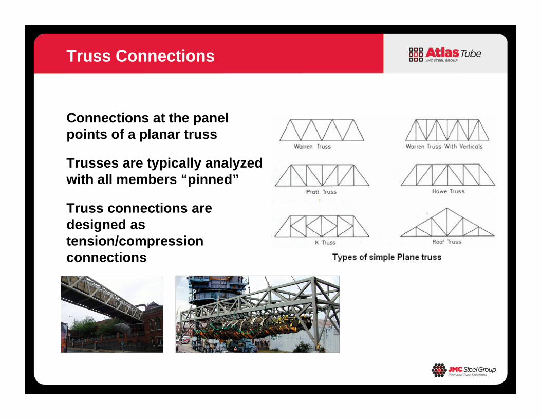
Connections at the panel points of a planar truss
Trusses are typically analyzed with all members “pinned”
Truss connections are designed as tension/compression connections
Truss Connections
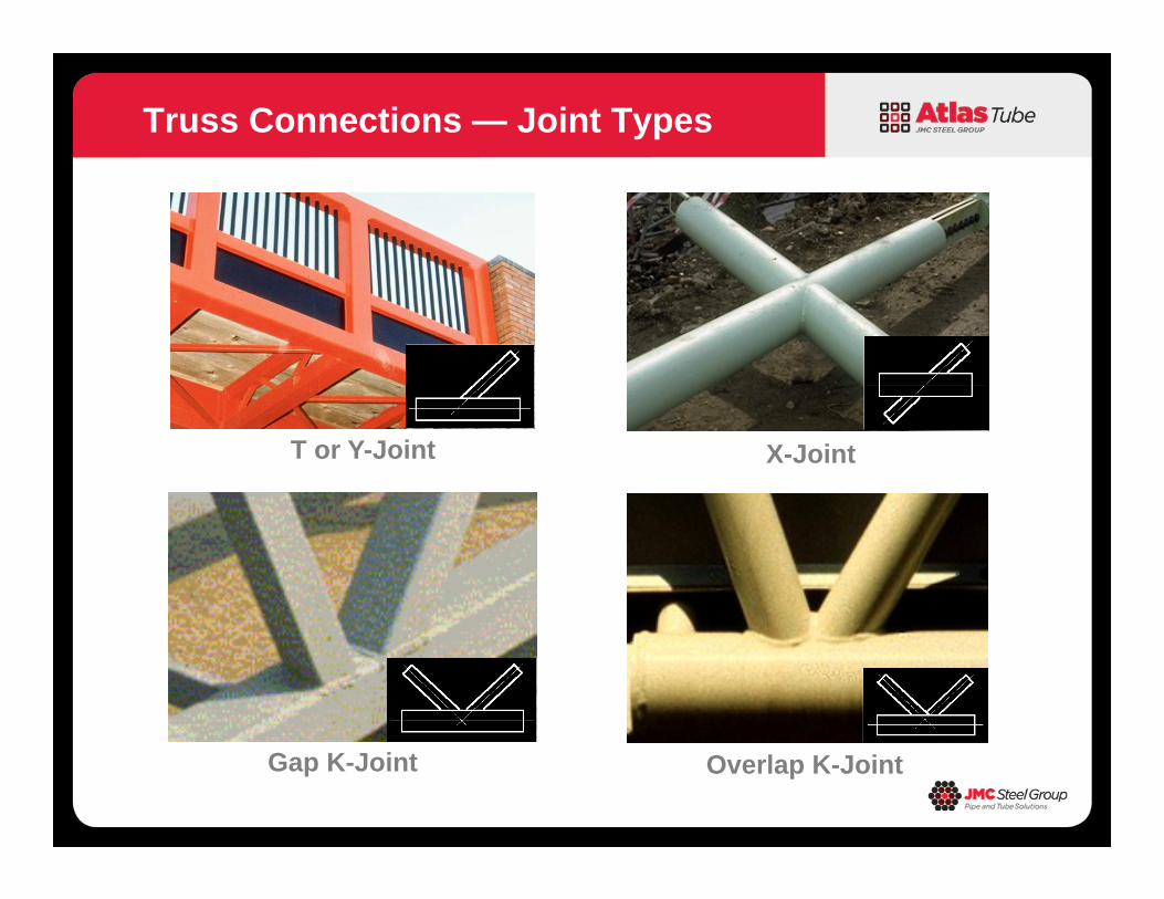
Truss Connections — Joint Types
Gap K-Joint Overlap K-Joint
T or Y-Joint X-Joint
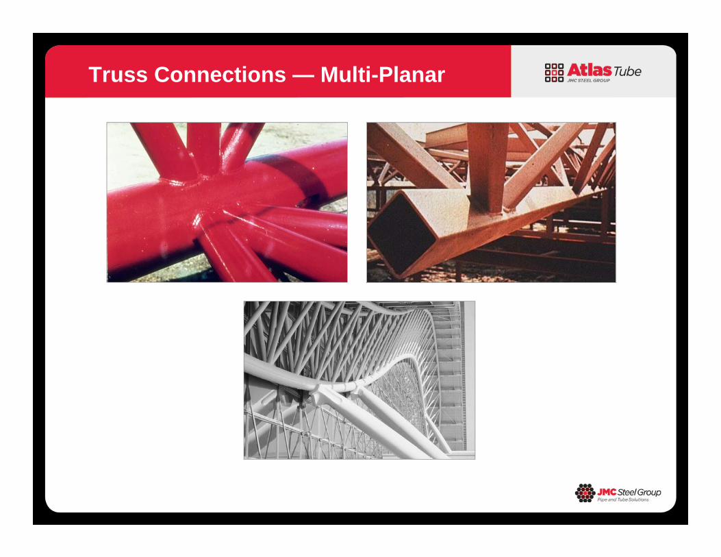
Truss Connections — Multi-Planar
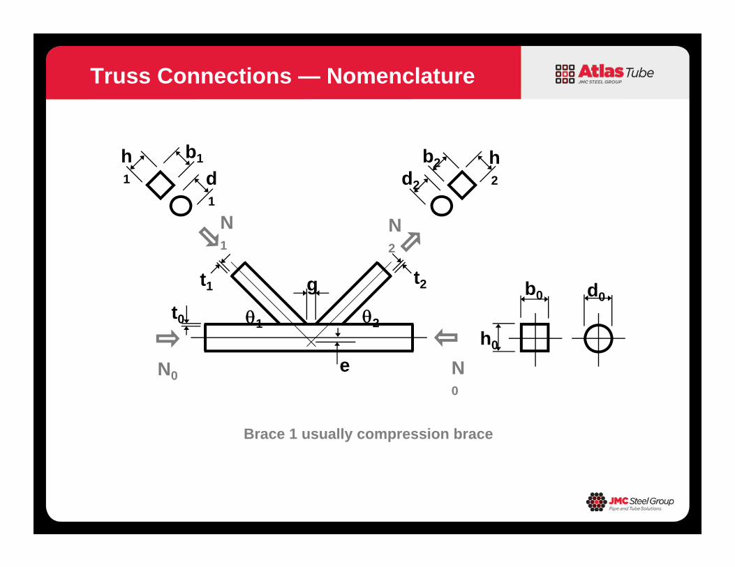
Truss Connections — Nomenclature
g
e
t1 t2
t0h0
b0 d0
21
b1
d1
h1
h2
b2d2
N1
N0
N2
N0
Brace 1 usually compression brace
Minimum weight does not equal minimum cost
Keep the number of different sizes small
Try to minimize number of connections– Warren trusses
Understand effects of joint configuration and connection design criteria before analyzing truss and selecting member sizes!
Truss Fabrication Costs
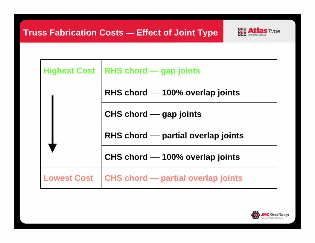
Truss Fabrication Costs — Effect of Joint Type
Highest Cost RHS chord — gap joints
RHS chord — 100% overlap joints
CHS chord — gap joints
RHS chord — partial overlap joints
CHS chord — 100% overlap joints
Lowest Cost CHS chord — partial overlap joints
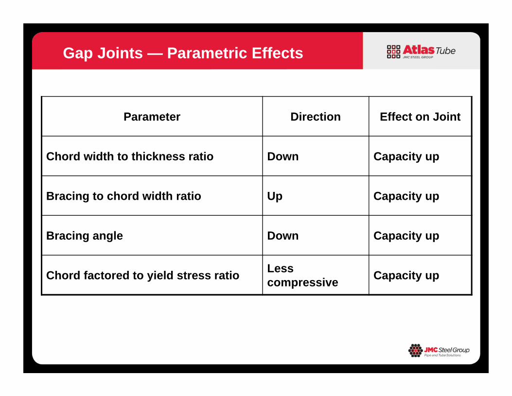
Gap Joints — Parametric Effects
Parameter Direction Effect on Joint
Chord width to thickness ratio Down Capacity up
Bracing to chord width ratio Up Capacity up
Bracing angle Down Capacity up
Chord factored to yield stress ratio Less compressive Capacity up
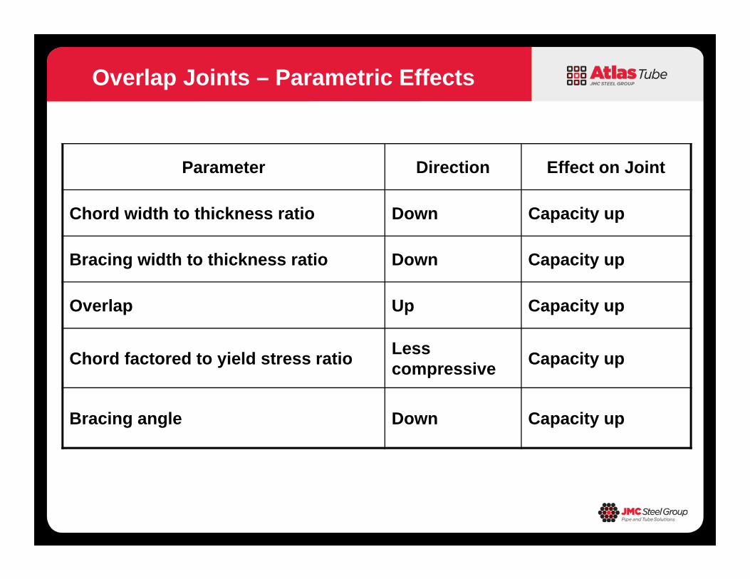
Overlap Joints – Parametric Effects
Parameter Direction Effect on Joint
Chord width to thickness ratio Down Capacity up
Bracing width to thickness ratio Down Capacity up
Overlap Up Capacity up
Chord factored to yield stress ratio Less compressive Capacity up
Bracing angle Down Capacity up
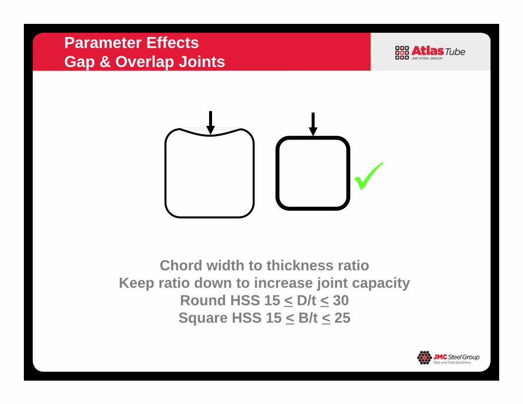
Parameter EffectsGap & Overlap Joints
Chord width to thickness ratioKeep ratio down to increase joint capacity
Round HSS 15 < D/t < 30Square HSS 15 < B/t < 25
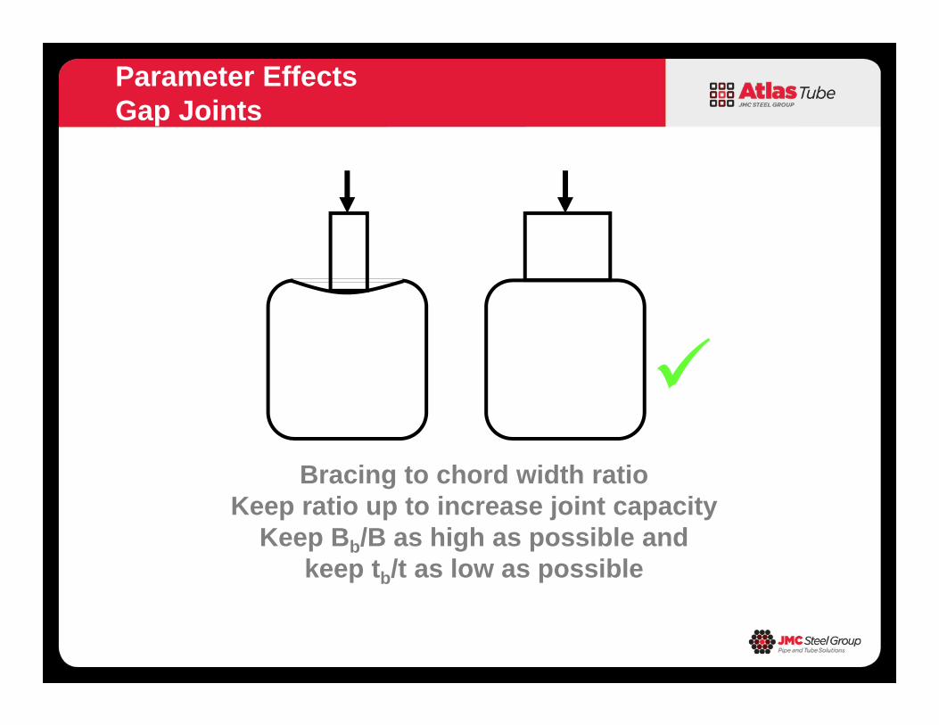
Parameter EffectsGap Joints
Bracing to chord width ratio
Keep ratio up to increase joint capacityKeep Bb/B as high as possible and
keep tb/t as low as possible
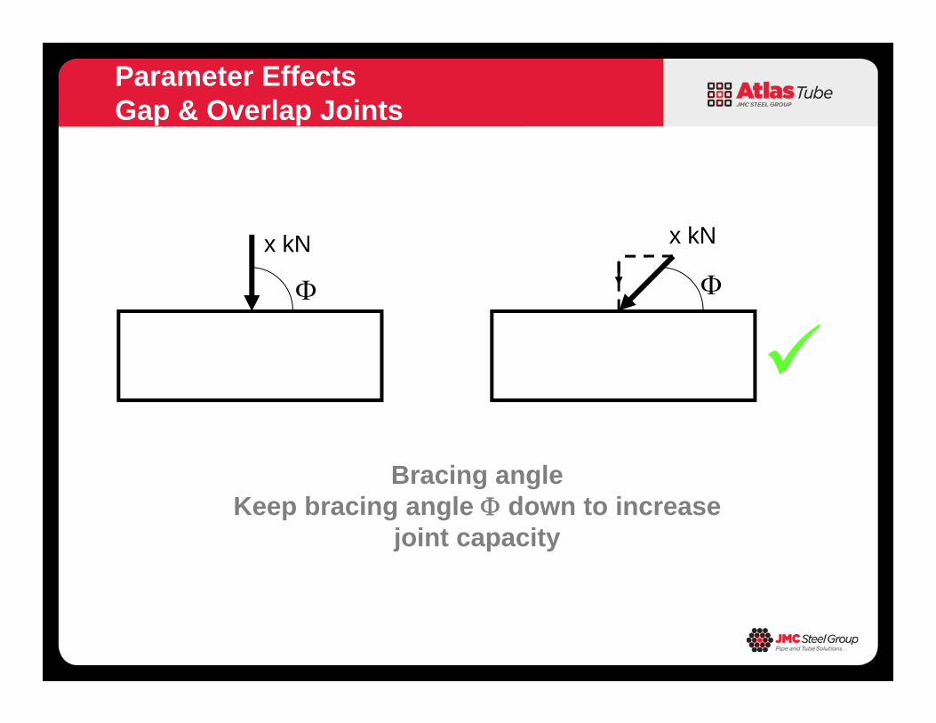
Parameter EffectsGap & Overlap Joints
x kN x kN
Bracing angleKeep bracing angle down to increase
joint capacity
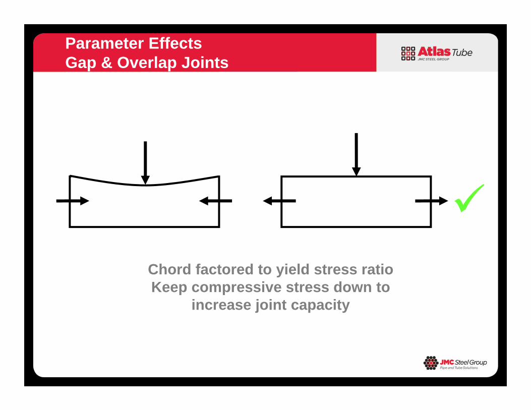
Parameter EffectsGap & Overlap Joints
Chord factored to yield stress ratioKeep compressive stress down to
increase joint capacity
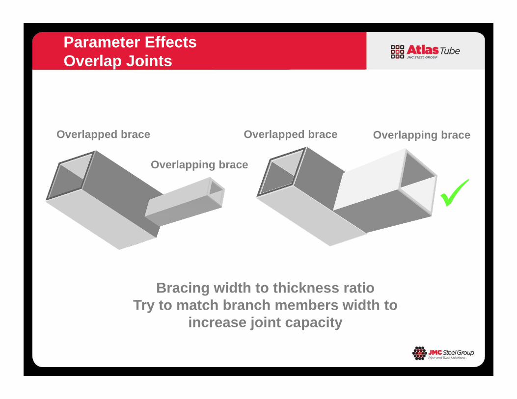
Parameter EffectsOverlap Joints
Overlapped brace
Overlapping brace
Overlapped brace Overlapping brace
Bracing width to thickness ratioTry to match branch members width to
increase joint capacity
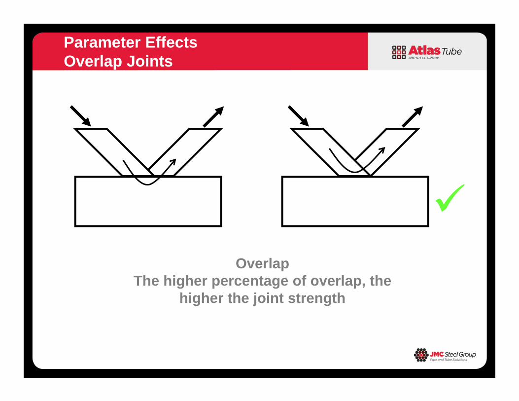
Parameter EffectsOverlap Joints
Overlap
The higher percentage of overlap, the higher the joint strength
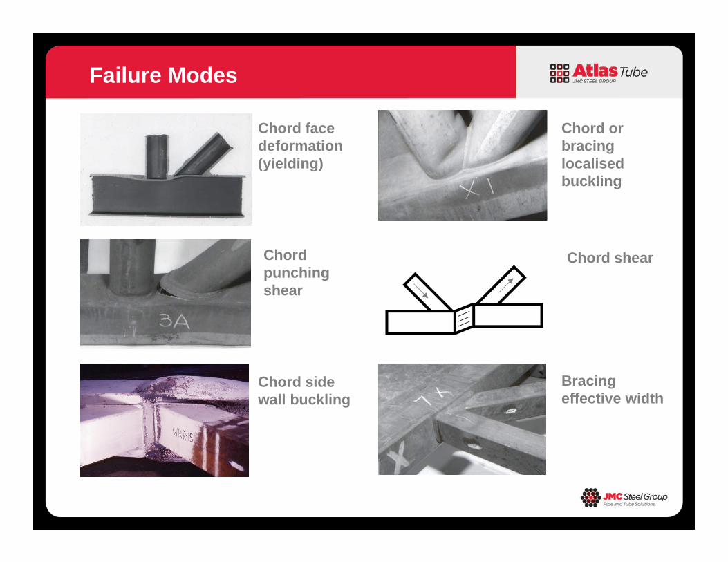
Failure Modes
Chord facedeformation(yielding)
Chord sidewall buckling
Chordpunchingshear
Bracing effective width
Chord orbracinglocalisedbuckling
Chord shear
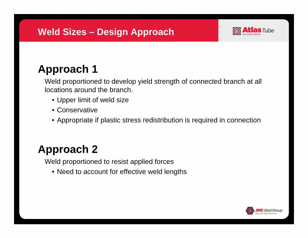
Approach 1Weld proportioned to develop yield strength of connected branch at all locations around the branch.
• Upper limit of weld size• Conservative• Appropriate if plastic stress redistribution is required in connection
Approach 2Weld proportioned to resist applied forces
• Need to account for effective weld lengths
Weld Sizes – Design Approach
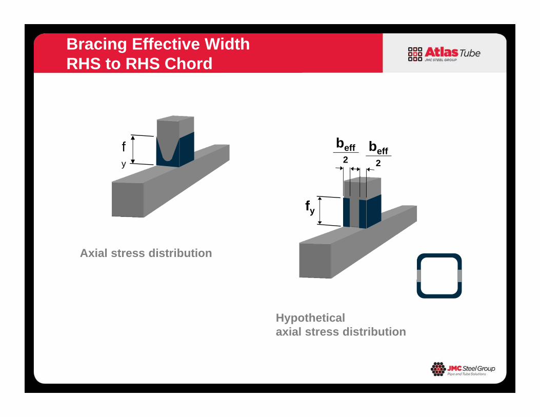
Bracing Effective WidthRHS to RHS Chord
Axial stress distribution
fy
Hypotheticalaxial stress distribution
fy
beff2
beff2
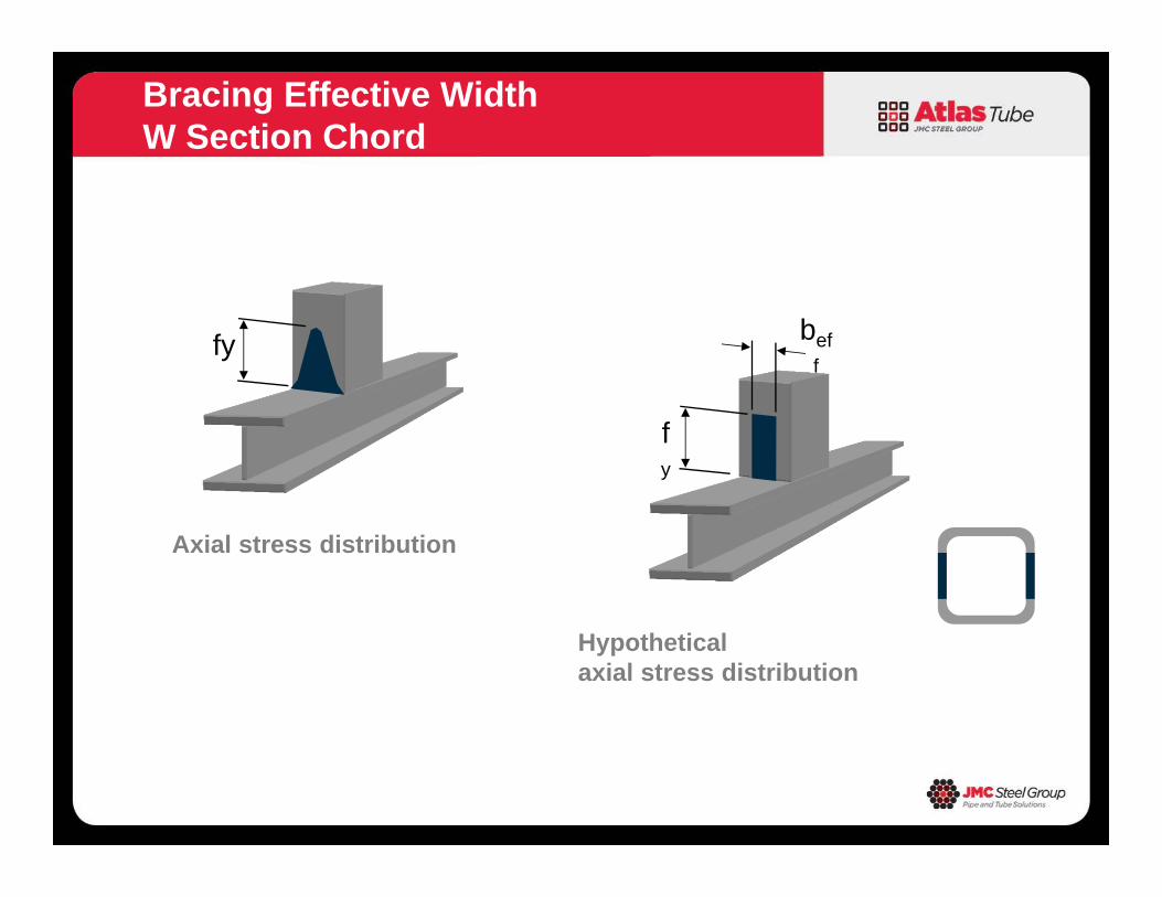
Bracing Effective WidthW Section Chord
Axial stress distribution
fy
Hypotheticalaxial stress distribution
fy
beff
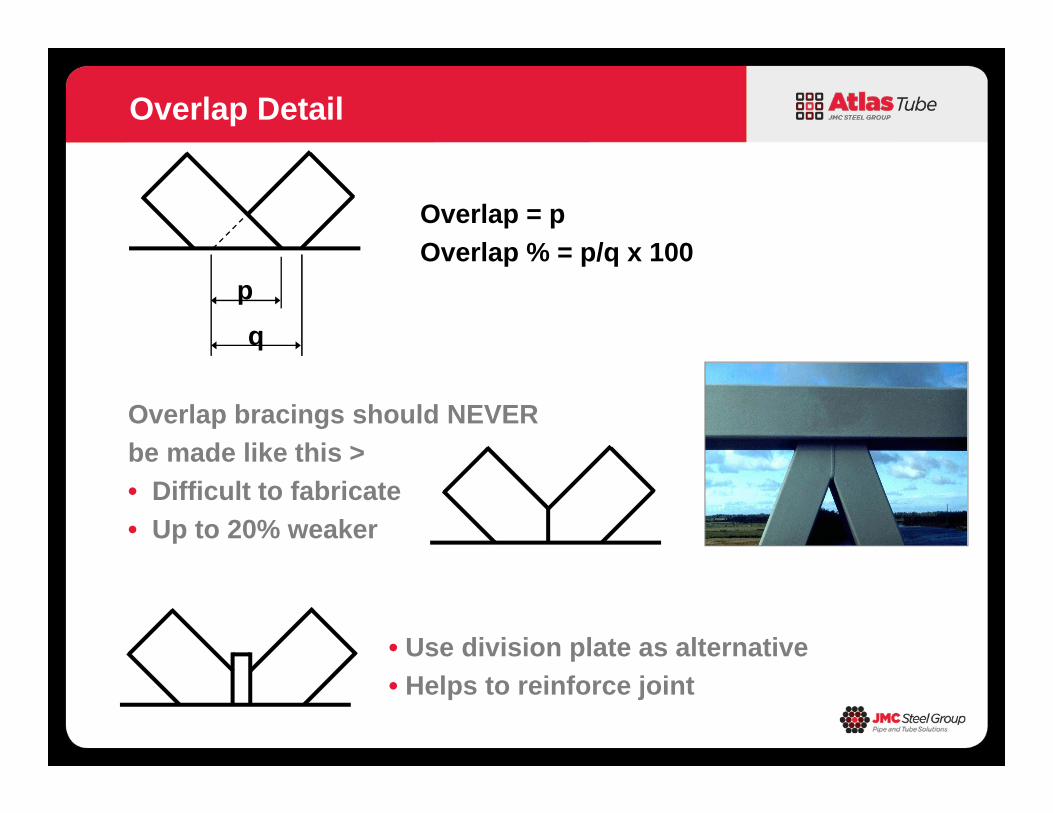
Overlap = pOverlap % = p/q x 100
Overlap Detail
pq
Overlap bracings should NEVERbe made like this >• Difficult to fabricate• Up to 20% weaker
• Use division plate as alternative• Helps to reinforce joint
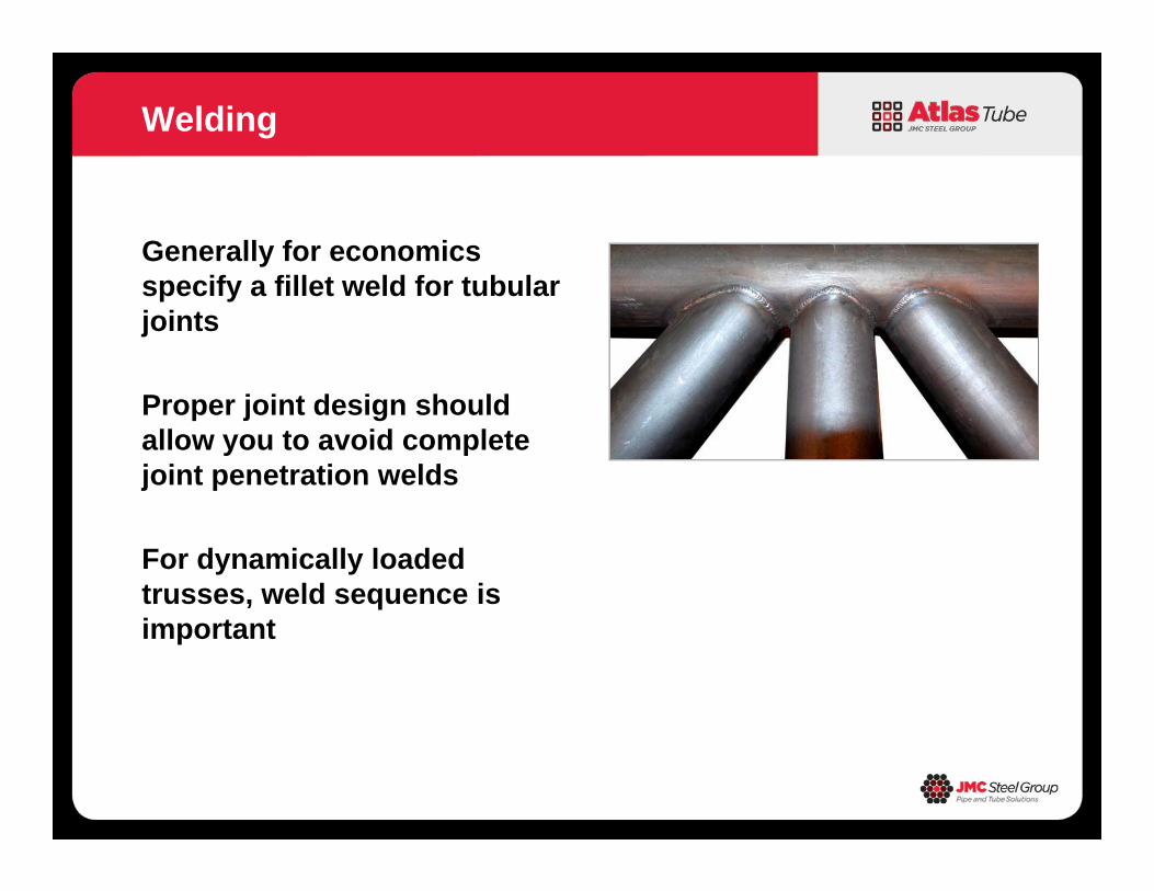
Generally for economics specify a fillet weld for tubular joints
Proper joint design should allow you to avoid complete joint penetration welds
For dynamically loaded trusses, weld sequence is important
Welding

Joint capacity is dependant upon• Brace angle• Bracing width to
chord width ratio• Chord width to
thickness ratio• Gap or overlap bracings• Chord compressive stress
Summary
Introduction HSS General Overview Types of HSS Connections Truss Connections Moment Connections
Topics
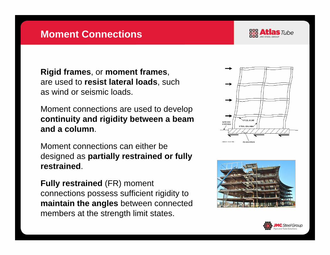
Rigid frames, or moment frames, are used to resist lateral loads, such as wind or seismic loads.
Moment connections are used to develop continuity and rigidity between a beam and a column.
Moment connections can either be designed as partially restrained or fully restrained.
Fully restrained (FR) moment connections possess sufficient rigidity to maintain the angles between connected members at the strength limit states.
Moment Connections
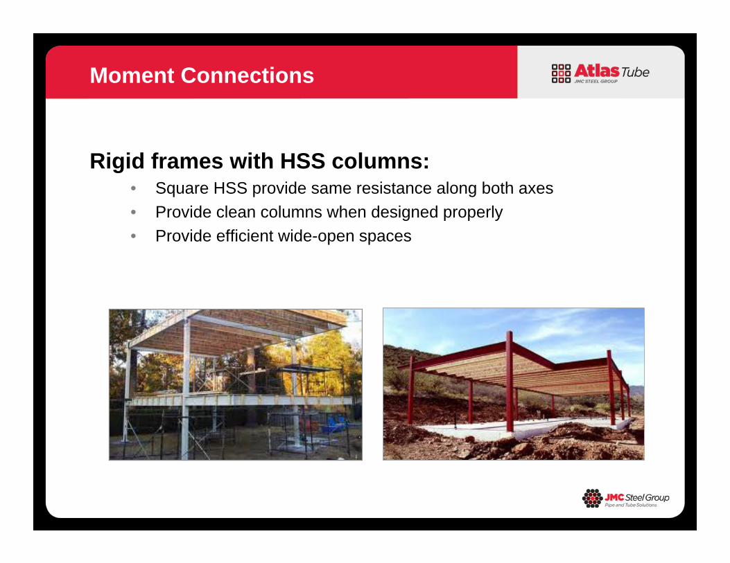
Rigid frames with HSS columns:• Square HSS provide same resistance along both axes• Provide clean columns when designed properly• Provide efficient wide-open spaces
Moment Connections
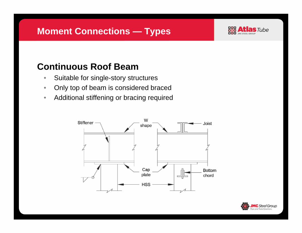
Continuous Roof Beam• Suitable for single-story structures• Only top of beam is considered braced• Additional stiffening or bracing required
Moment Connections — Types
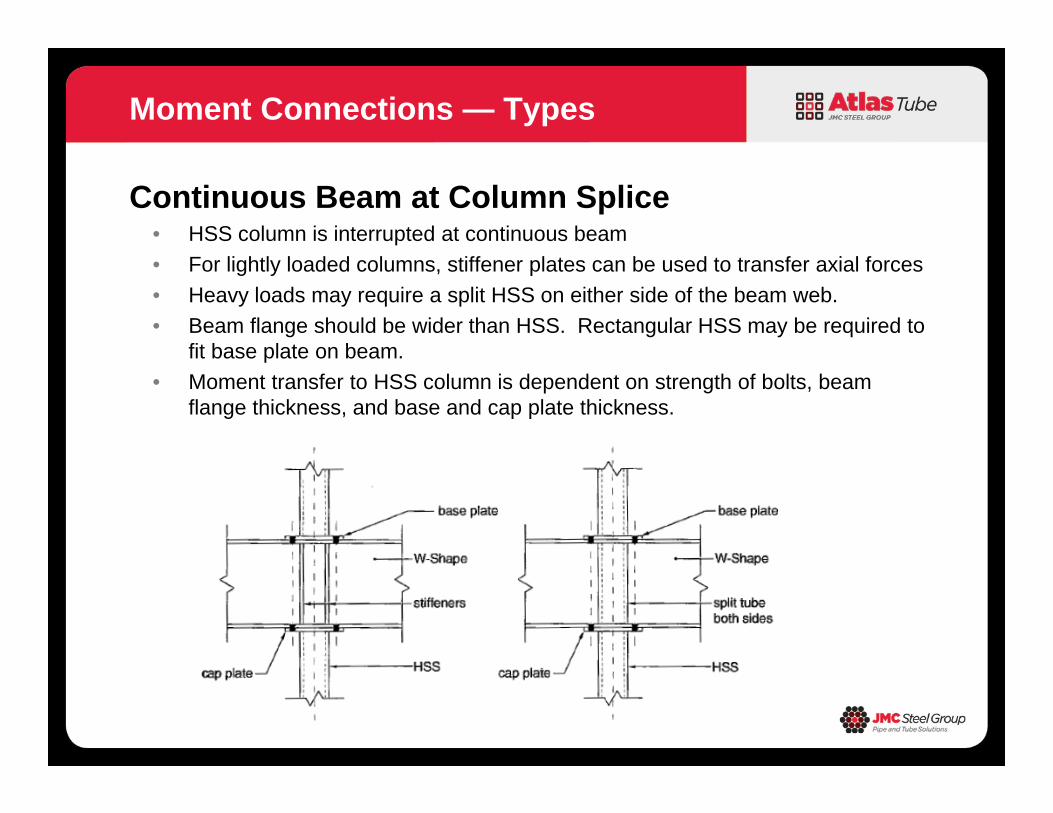
Continuous Beam at Column Splice• HSS column is interrupted at continuous beam• For lightly loaded columns, stiffener plates can be used to transfer axial forces• Heavy loads may require a split HSS on either side of the beam web.• Beam flange should be wider than HSS. Rectangular HSS may be required to
fit base plate on beam.• Moment transfer to HSS column is dependent on strength of bolts, beam
flange thickness, and base and cap plate thickness.
Moment Connections — Types
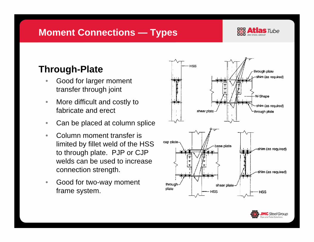
Through-Plate• Good for larger moment
transfer through joint
• More difficult and costly to fabricate and erect
• Can be placed at column splice
• Column moment transfer is limited by fillet weld of the HSS to through plate. PJP or CJP welds can be used to increase connection strength.
• Good for two-way moment frame system.
Moment Connections — Types
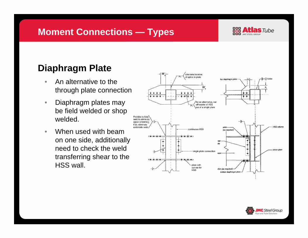
Diaphragm Plate• An alternative to the
through plate connection.
• Diaphragm plates may be field welded or shop welded.
• When used with beam on one side, additionally need to check the weld transferring shear to the HSS wall.
Moment Connections — Types
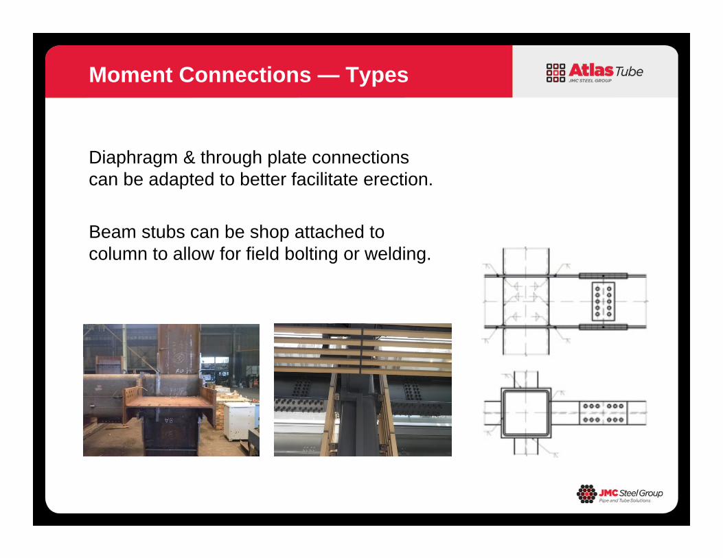
Diaphragm & through plate connections can be adapted to better facilitate erection.
Beam stubs can be shop attached to column to allow for field bolting or welding.
Moment Connections — Types
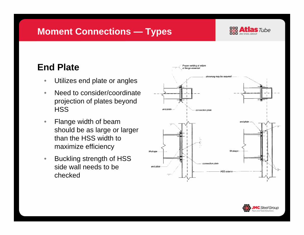
End Plate• Utilizes end plate or angles
• Need to consider/coordinate projection of plates beyond HSS
• Flange width of beam should be as large or larger than the HSS width to maximize efficiency
• Buckling strength of HSS side wall needs to be checked
Moment Connections — Types
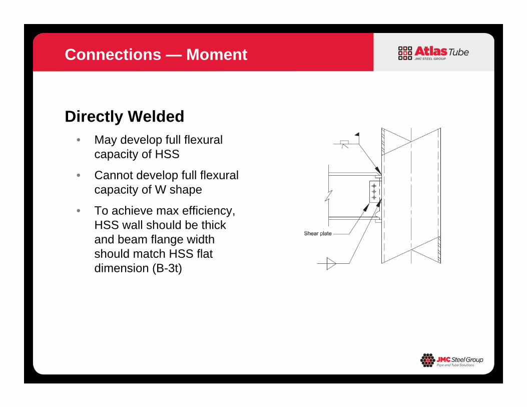
Directly Welded• May develop full flexural
capacity of HSS
• Cannot develop full flexural capacity of W shape
• To achieve max efficiency, HSS wall should be thick and beam flange width should match HSS flat dimension (B-3t)
Connections — Moment