Embed Size (px)
Citation preview
Introduction to SoC modeling and Models of Computation
TKT-1527 Digital System Design IssuesTero Arpinen
1
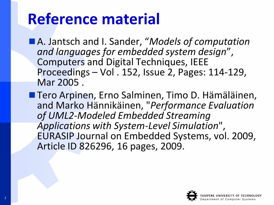
Reference materialA. Jantsch and I. Sander, “Models of computation
and languages for embedded system design”, Computers and Digital Techniques, IEEE Proceedings – Vol . 152, Issue 2, Pages: 114-129, Mar 2005 .
Tero Arpinen, Erno Salminen, Timo D. Hämäläinen, and Marko Hännikäinen, "Performance Evaluation of UML2-Modeled Embedded Streaming Applications with System-Level Simulation", EURASIP Journal on Embedded Systems, vol. 2009, Article ID 826296, 16 pages, 2009.
2
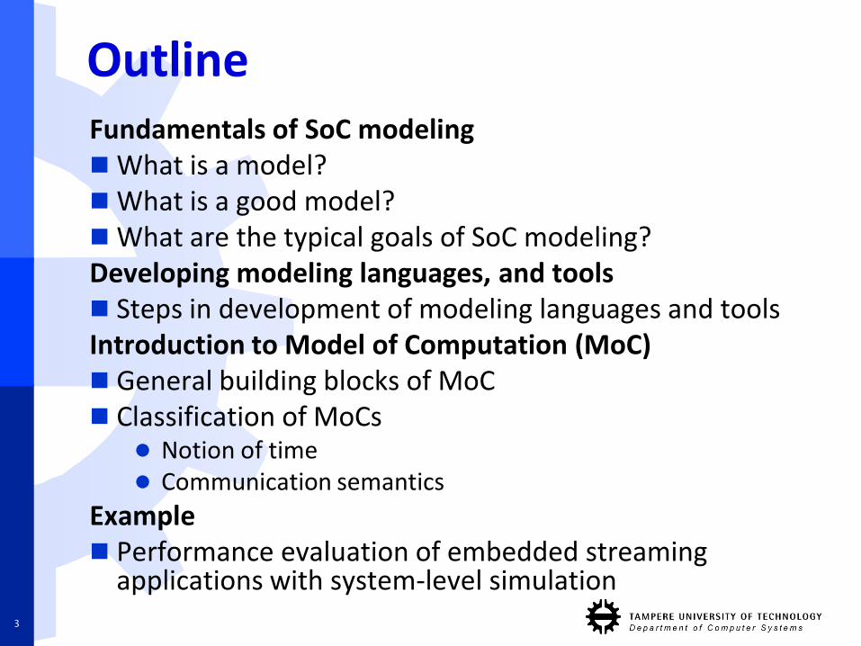
OutlineFundamentals of SoC modelingWhat is a model?What is a good model?What are the typical goals of SoC modeling?Developing modeling languages, and tools Steps in development of modeling languages and toolsIntroduction to Model of Computation (MoC) General building blocks of MoC Classification of MoCs
Notion of time Communication semantics
Example Performance evaluation of embedded streaming
applications with system-level simulation3
Fundamentals of SoCmodeling
4
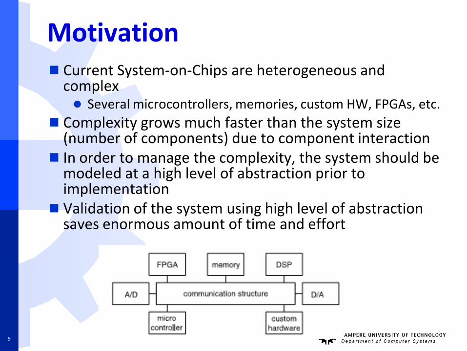
Motivation Current System-on-Chips are heterogeneous and
complex Several microcontrollers, memories, custom HW, FPGAs, etc.
Complexity grows much faster than the system size (number of components) due to component interaction
In order to manage the complexity, the system should be modeled at a high level of abstraction prior to implementation
Validation of the system using high level of abstraction saves enormous amount of time and effort
5
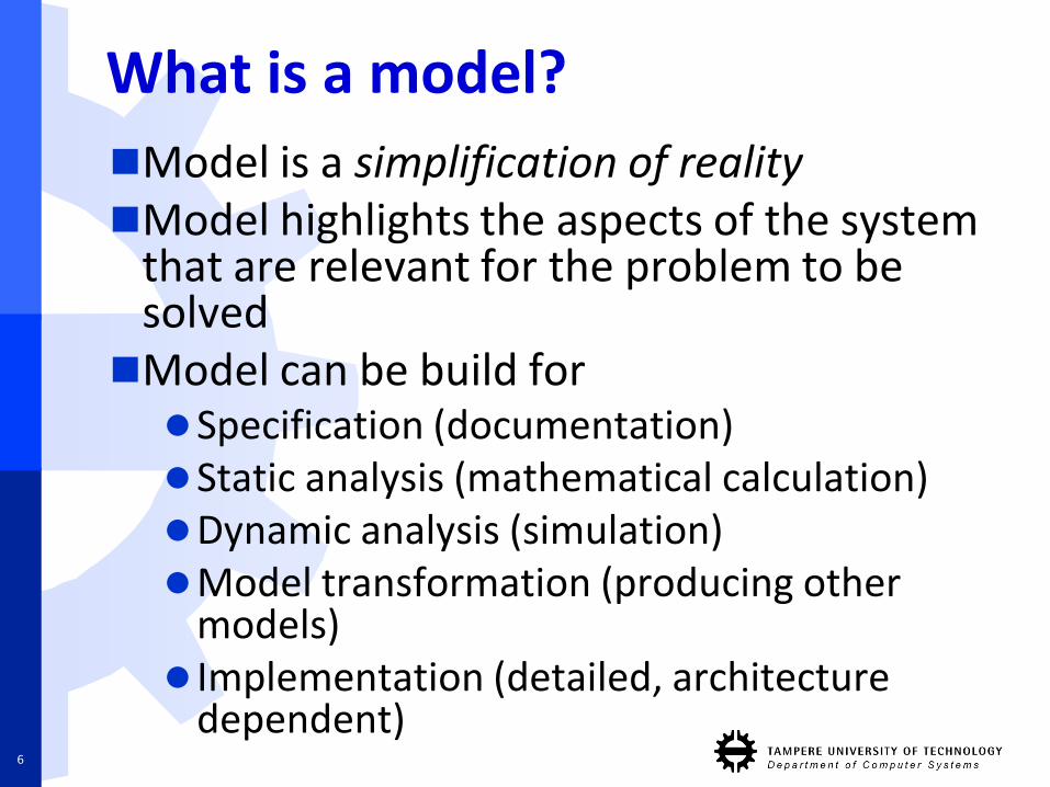
What is a model?
Model is a simplification of realityModel highlights the aspects of the system
that are relevant for the problem to be solvedModel can be build forSpecification (documentation)Static analysis (mathematical calculation)Dynamic analysis (simulation)Model transformation (producing other
models) Implementation (detailed, architecture
dependent)6
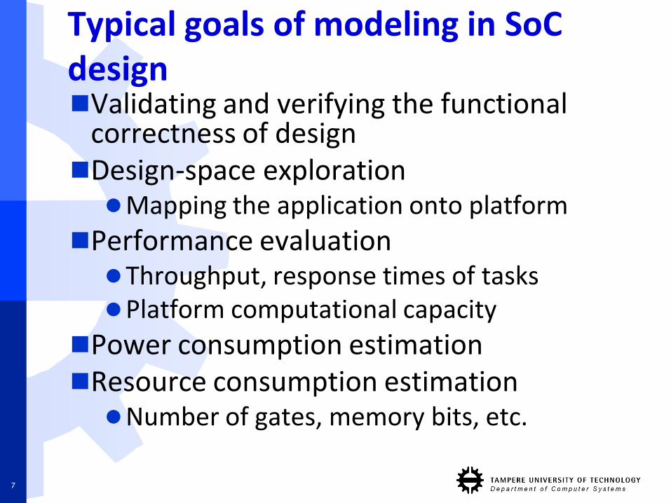
Typical goals of modeling in SoCdesignValidating and verifying the functional
correctness of designDesign-space explorationMapping the application onto platform
Performance evaluationThroughput, response times of tasksPlatform computational capacity
Power consumption estimationResource consumption estimationNumber of gates, memory bits, etc.
7
Weapons for modeling
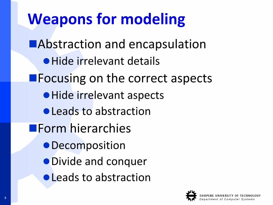
Abstraction and encapsulationHide irrelevant details
Focusing on the correct aspects Hide irrelevant aspects
Leads to abstraction
Form hierarchies Decomposition
Divide and conquer
Leads to abstraction
8
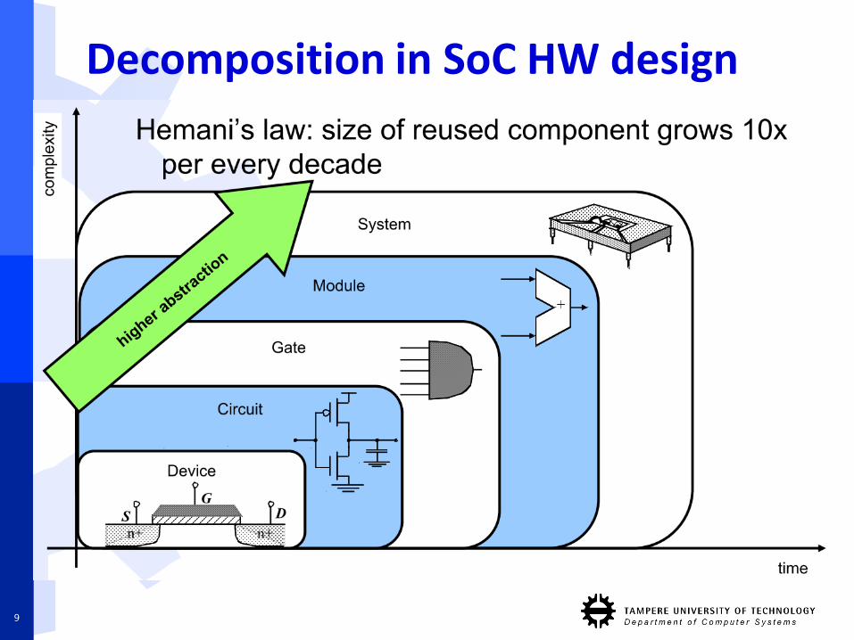
Decomposition in SoC HW design
9
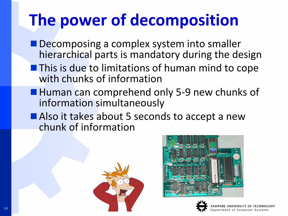
The power of decompositionDecomposing a complex system into smaller
hierarchical parts is mandatory during the designThis is due to limitations of human mind to cope
with chunks of informationHuman can comprehend only 5-9 new chunks of
information simultaneouslyAlso it takes about 5 seconds to accept a new
chunk of information
10
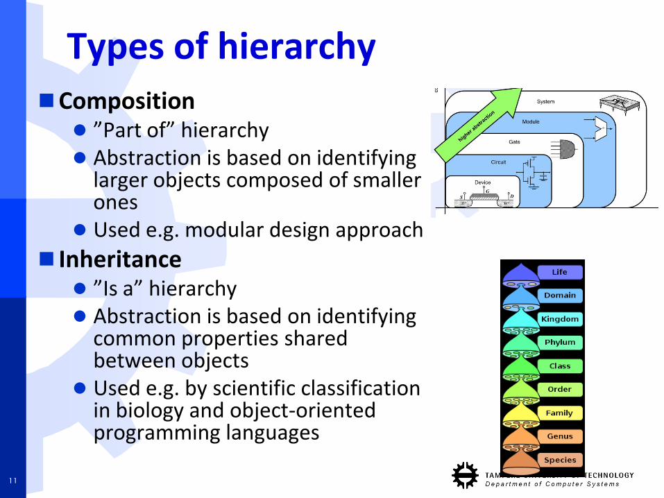
Types of hierarchyComposition
”Part of” hierarchy Abstraction is based on identifying
larger objects composed of smallerones
Used e.g. modular design approach
Inheritance ”Is a” hierarchy Abstraction is based on identifying
common properties sharedbetween objects
Used e.g. by scientific classificationin biology and object-orientedprogramming languages
11
Five attributes of complex system
Hierarchic structureComplex system is composed of interrelated
subsystems that have in turn their own subsystems, and so on.
Complex system is a function of its components and hierarchic structure of its components
Relative primitivesThe choice of what components of the
system are primitive is dependent of the observer.
E.g. transistor vs. logic gate or algorithm vs. CPU instruction
12
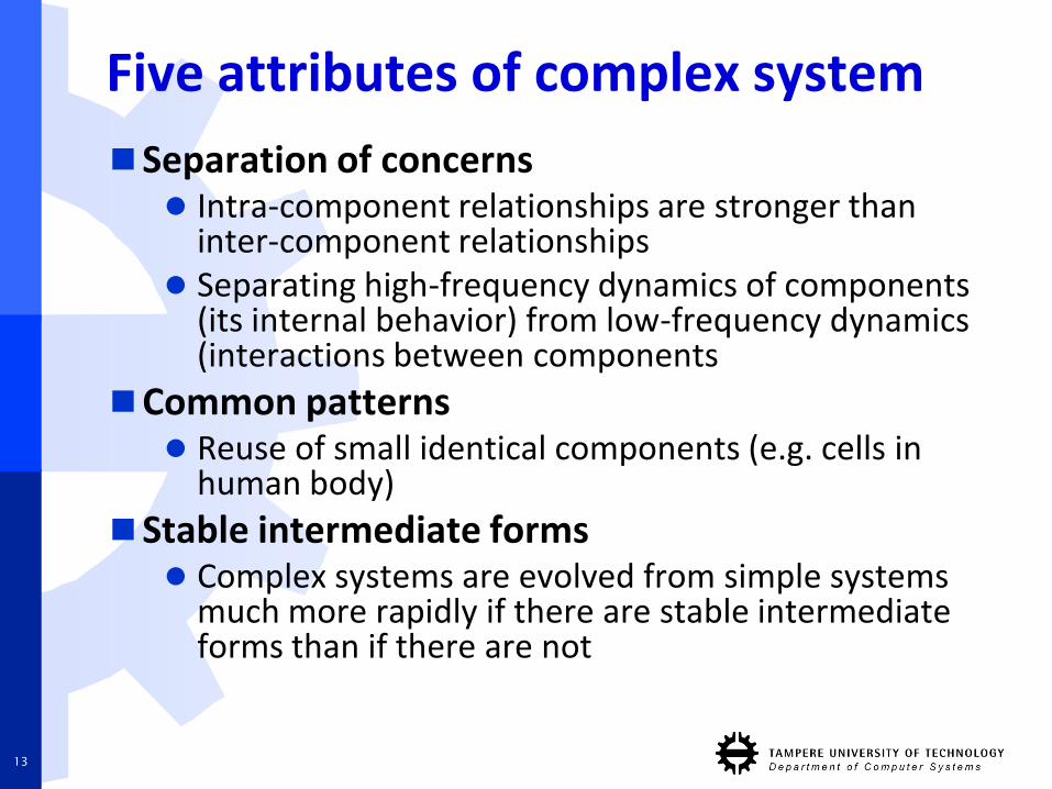
Five attributes of complex system
Separation of concerns Intra-component relationships are stronger than
inter-component relationships Separating high-frequency dynamics of components
(its internal behavior) from low-frequency dynamics (interactions between components
Common patterns Reuse of small identical components (e.g. cells in
human body)
Stable intermediate forms Complex systems are evolved from simple systems
much more rapidly if there are stable intermediate forms than if there are not
13
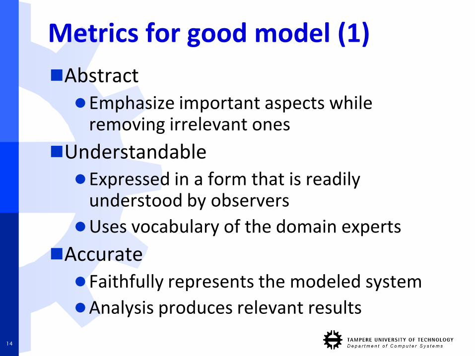
Metrics for good model (1)
AbstractEmphasize important aspects while
removing irrelevant ones
UnderstandableExpressed in a form that is readily
understood by observers
Uses vocabulary of the domain experts
AccurateFaithfully represents the modeled system
Analysis produces relevant results
14
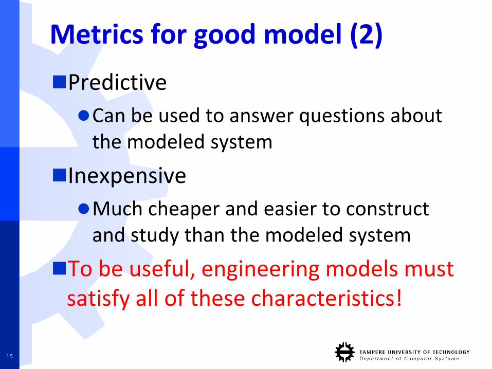
Metrics for good model (2)
Predictive
Can be used to answer questions about the modeled system
Inexpensive
Much cheaper and easier to construct and study than the modeled system
To be useful, engineering models must satisfy all of these characteristics!
15
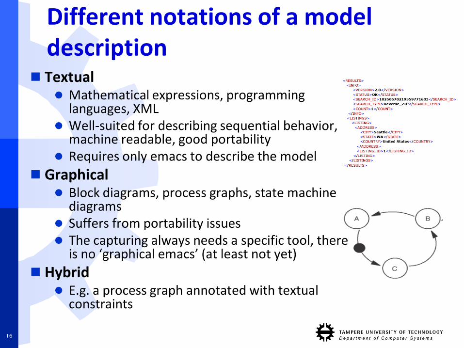
Different notations of a model description
Textual Mathematical expressions, programming
languages, XML Well-suited for describing sequential behavior,
machine readable, good portability Requires only emacs to describe the model
Graphical Block diagrams, process graphs, state machine
diagrams Suffers from portability issues The capturing always needs a specific tool, there
is no ‘graphical emacs’ (at least not yet)
Hybrid E.g. a process graph annotated with textual
constraints
16
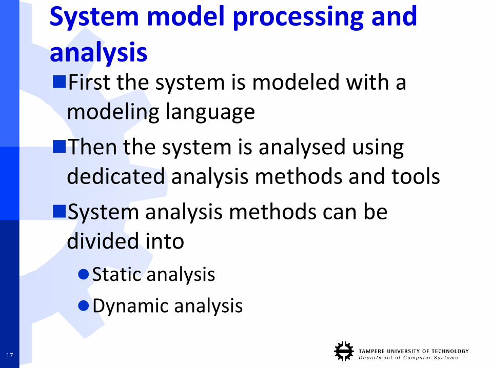
System model processing and analysisFirst the system is modeled with a
modeling language
Then the system is analysed using dedicated analysis methods and tools
System analysis methods can be divided into
Static analysis
Dynamic analysis
17
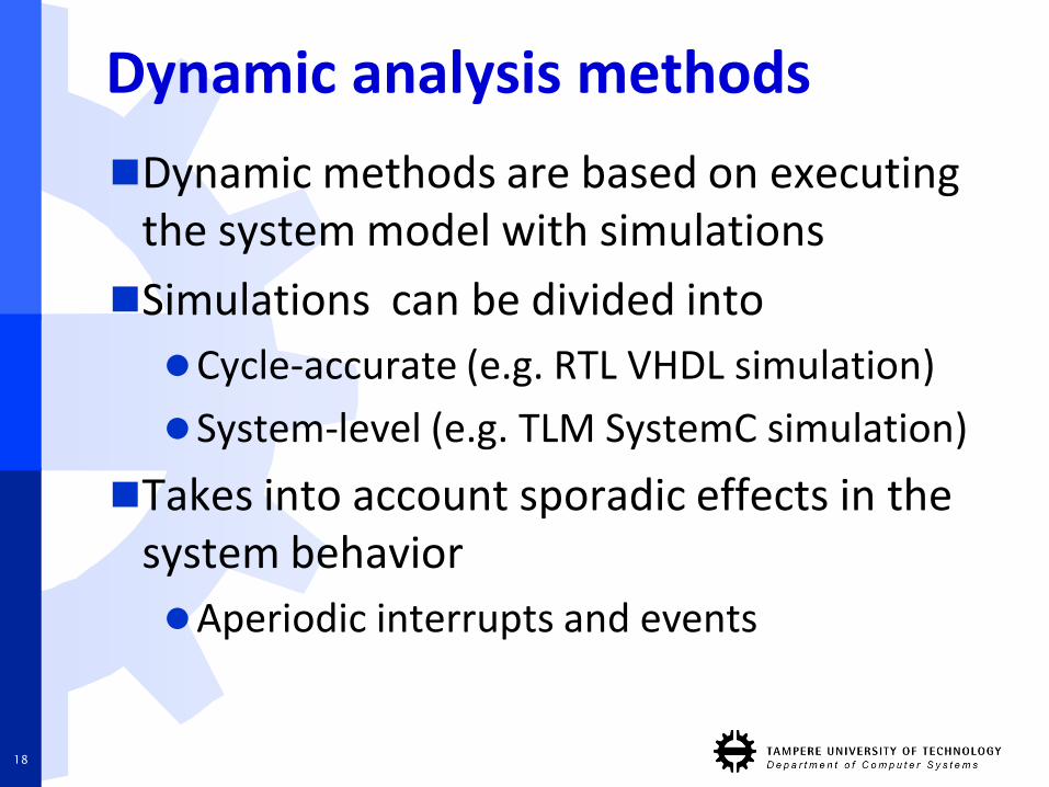
Dynamic analysis methods
Dynamic methods are based on executingthe system model with simulations
Simulations can be divided into
Cycle-accurate (e.g. RTL VHDL simulation)
System-level (e.g. TLM SystemC simulation)
Takes into account sporadic effects in the system behavior
Aperiodic interrupts and events
18
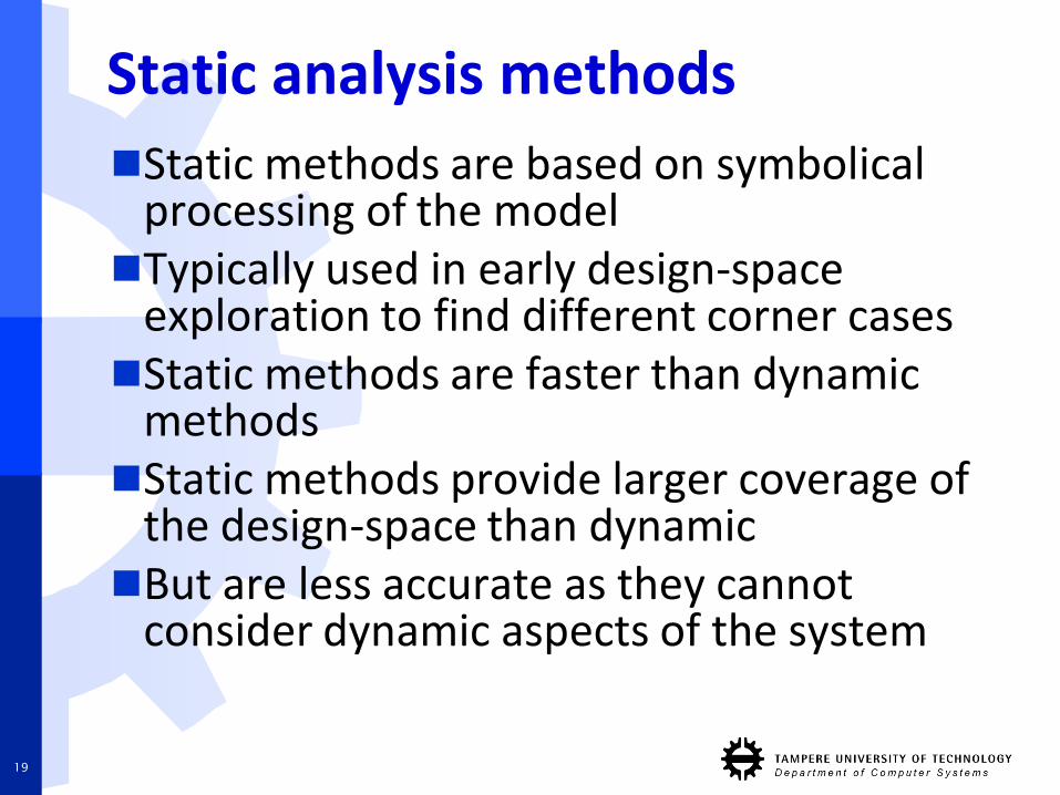
Static analysis methods
Static methods are based on symbolicalprocessing of the modelTypically used in early design-space
exploration to find different corner casesStatic methods are faster than dynamic
methodsStatic methods provide larger coverage of
the design-space than dynamicBut are less accurate as they cannot
consider dynamic aspects of the system
19
Summary: benefits of modeling
Problems are better understood
Problems are easier to analyse and solve
Problems are spotted earlier in the design
Problems are easier to communicate between designers
Altogether, time and effort is saved
20
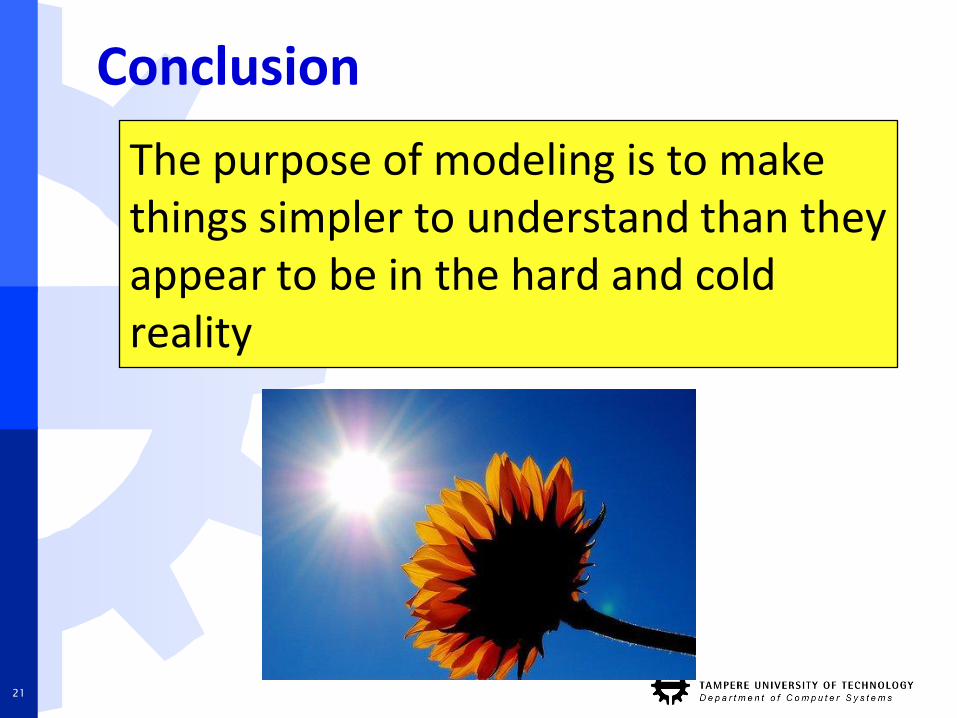
Conclusion
The purpose of modeling is to make things simpler to understand than they appear to be in the hard and cold reality
21
Developing modelinglanguages and tools
22
Steps for developing modeling languages and analysis tools1. Formulation of meta-model
Defining semantics for the modelinglanguage
2. Developing methods for modelpresentation
Defining notations for the modelinglanguage
3. Development of analysis tools accordingto defined modeling methods
23
Formulation of meta-model
Meta-model is a model behind a model
It determines the rules how a model is constructed
It defines model elements that can be used for modeling and their semantics
The formulation is done by considering the purpose of the model
24
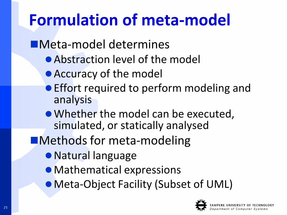
Formulation of meta-model
Meta-model determinesAbstraction level of the modelAccuracy of the modelEffort required to perform modeling and
analysisWhether the model can be executed,
simulated, or statically analysed
Methods for meta-modelingNatural languageMathematical expressionsMeta-Object Facility (Subset of UML)
25
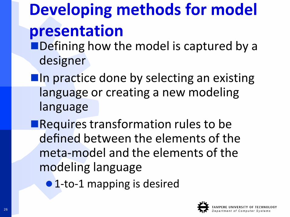
Developing methods for model presentationDefining how the model is captured by a
designer
In practice done by selecting an existinglanguage or creating a new modelinglanguage
Requires transformation rules to be defined between the elements of the meta-model and the elements of the modeling language1-to-1 mapping is desired
26
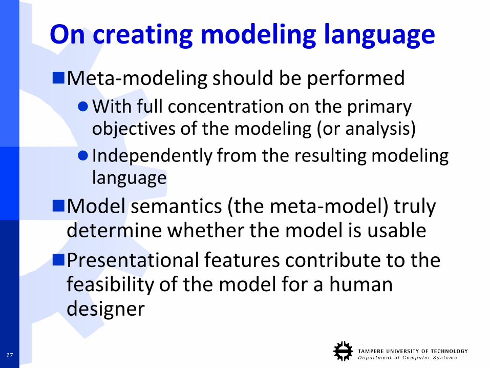
On creating modeling language
Meta-modeling should be performed With full concentration on the primary
objectives of the modeling (or analysis)
Independently from the resulting modeling language
Model semantics (the meta-model) truly determine whether the model is usable
Presentational features contribute to the feasibility of the model for a human designer
27
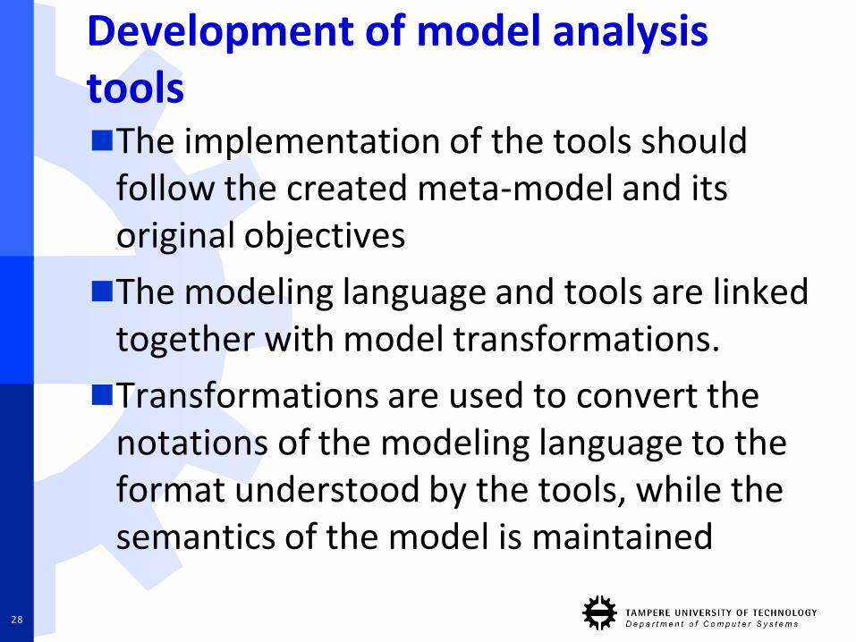
Development of model analysistoolsThe implementation of the tools should
follow the created meta-model and its original objectives
The modeling language and tools are linked together with model transformations.
Transformations are used to convert the notations of the modeling language to the format understood by the tools, while the semantics of the model is maintained
28
Introduction to Model of Computation
29
Model of Computation
Model of Computation (MoC) defines howcomputation of a system takes place in a structure of concurrent processesMoC semantics can be used to formulate an
abstract machine capable of executing a modelMoC is typically described with process (or
task) networksMoC describes the notion of time in the
process networkMoC determines the semantics how
processes communicate with each other
30
Model of Computation
Choosing a suitable MoC for the analysis is very important since each MoC have theirown propertiesThis is often done by selecting an existing
design/modeling languageDesign languages are not MoCs themselves
but they have underlying computationalmodelsFor instance VHDL, Verilog, and SystemC
share the same discrete-time, event-drivencomputational model
31
General building blocks of MoC
Event
Signal
Process
Evaluation cycle
32
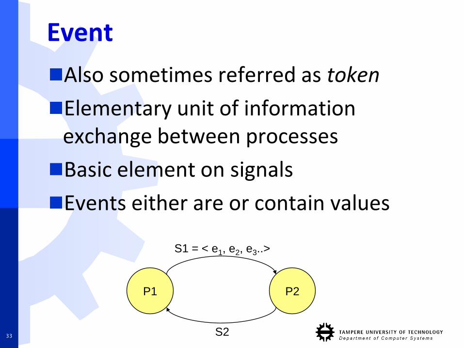
Event
Also sometimes referred as token
Elementary unit of information exchange between processes
Basic element on signals
Events either are or contain values
P1
S1 = < e1, e2, e3..>
P2
S233
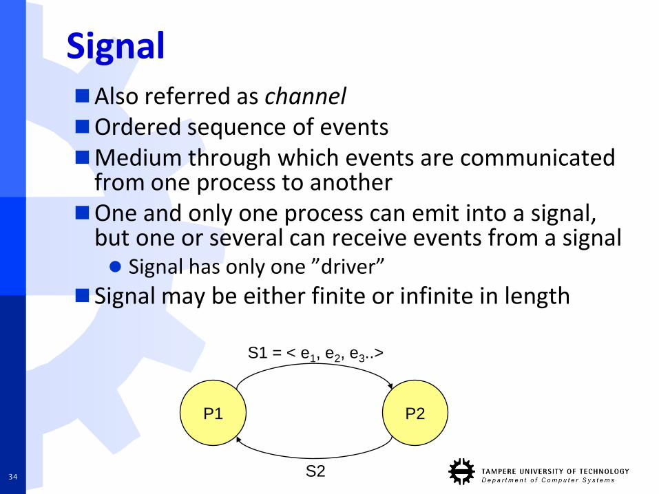
SignalAlso referred as channelOrdered sequence of eventsMedium through which events are communicated
from one process to anotherOne and only one process can emit into a signal,
but one or several can receive events from a signal Signal has only one ”driver”
Signal may be either finite or infinite in length
P1
S1 = < e1, e2, e3..>
P2
S234
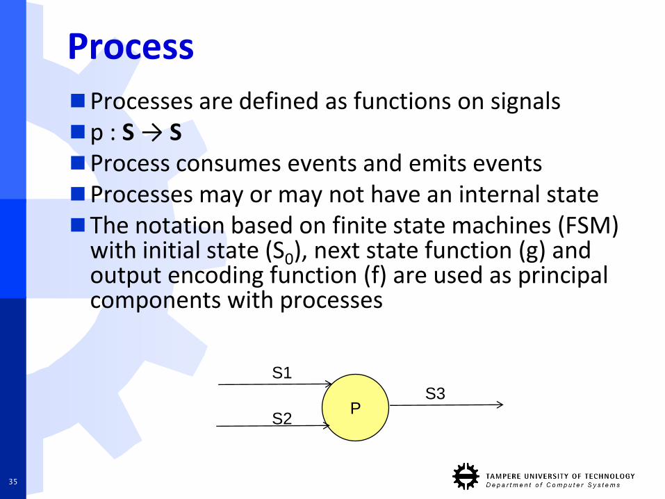
ProcessProcesses are defined as functions on signalsp : S → SProcess consumes events and emits eventsProcesses may or may not have an internal stateThe notation based on finite state machines (FSM)
with initial state (S0), next state function (g) and output encoding function (f) are used as principal components with processes
P
S1
S2
S3
35
Evaluation cycle
The activity of processes is divided into evaluation cyclesIn each evaluation cycle a process consumes
inputs, computes its internal state and emits outputsA process partitions its input and output
signals into subsequences corresponding its evaluation cycleDuring each evaluation cycle a process
consumes exactly one subsequence of each of its input signals and emits exactly one subsequence of each of its output signals
36
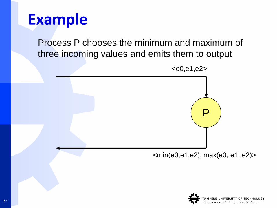
Example
P
37
Process P chooses the minimum and maximum of
three incoming values and emits them to output
<e0,e1,e2>
<min(e0,e1,e2), max(e0, e1, e2)>

1st evaluation cycle (i = 0)
P
3 19
31912
38
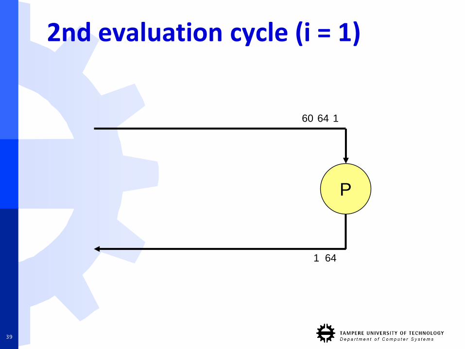
2nd evaluation cycle (i = 1)
P
1 64
16460
39
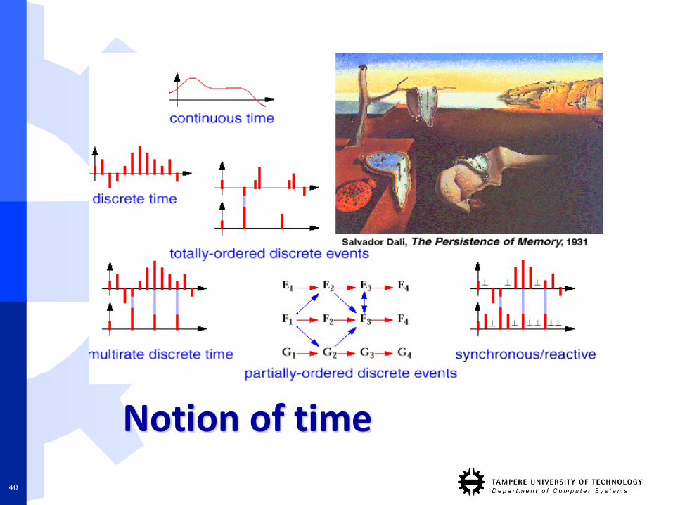
Notion of time
40
MoC categories based on notion of timeTimed
Continuous-time (e.g. Simulink)
Discrete-time (VHDL)
Syncronous time (RTL FSM)
Untimed
Kahn process network (~course exercise)
Data flow process network
Synchronous data flow
41
Continuous-time models
Time represented as a continuous set as real number valuesBehaviour represented as equations over
real numbers.Simulators for continuation time are
typically very slowDue to need for solving differential
equations
Thus, only small parts of system aremodeled with continuous time modelsTypically analogue and mixed-signal parts
42
Continuous-time models
Examples of continuous time MoC languages Simulink
VHDL-AMS
Modelica
Mixed-signal languages allow modeling of pure digital parts in discrete-time and analogparts in continuous-time MoC This allows simulations with acceptable
performance
E.g. VHDL-AMS
43
Discrete-time models
All events are associated with a timeinstant and time is represented with a discrete setFor example with integer or natural
numbers
Both VHDL and Verilog use discrete-timemodel for their simulation semanticsA simulator for discrete-time MoCs is
usually implemented with a global eventqueue that automatically sorts occuringevents
44
Discrete-time vs. discrete-event
Discrete-time is not the same as discrete-event
Discrete-event means that values of eventsare taken from a discrete set
So there are four different combinations
Cont.-time / Cont.-event
Cont.-time /Discr.-event
Discr.-time / Cont.-event
Discr.-time / Discr.-event
45
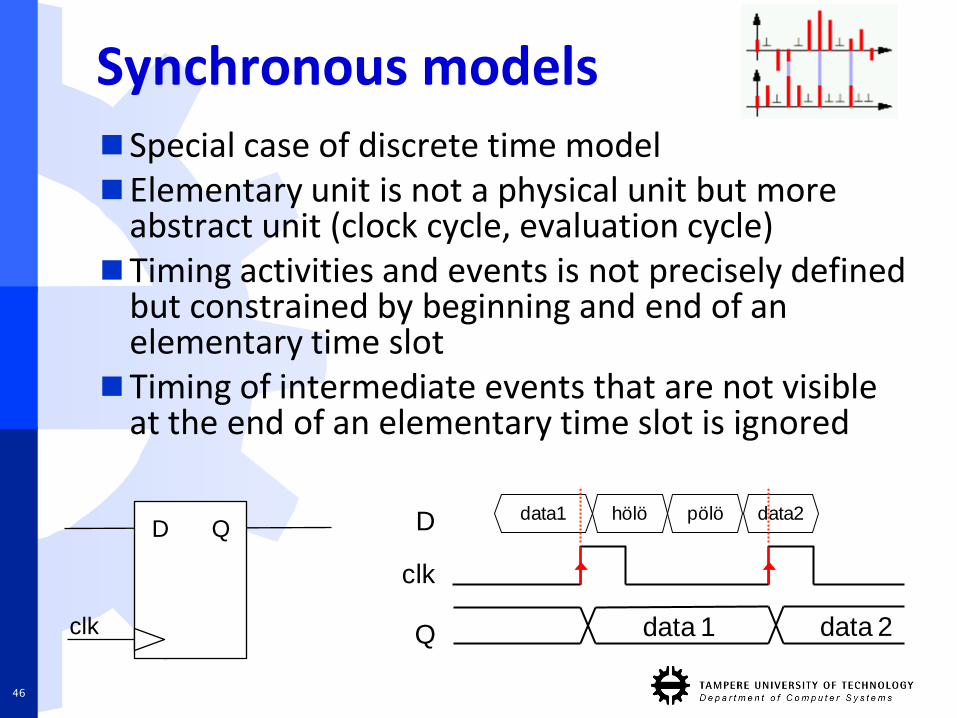
Synchronous modelsSpecial case of discrete time modelElementary unit is not a physical unit but more
abstract unit (clock cycle, evaluation cycle)Timing activities and events is not precisely defined
but constrained by beginning and end of an elementary time slot
Timing of intermediate events that are not visibleat the end of an elementary time slot is ignored
data 1
D
clk
Q data 2
hölödata1 pölö data2
46
D Q
clk
Synchronous models
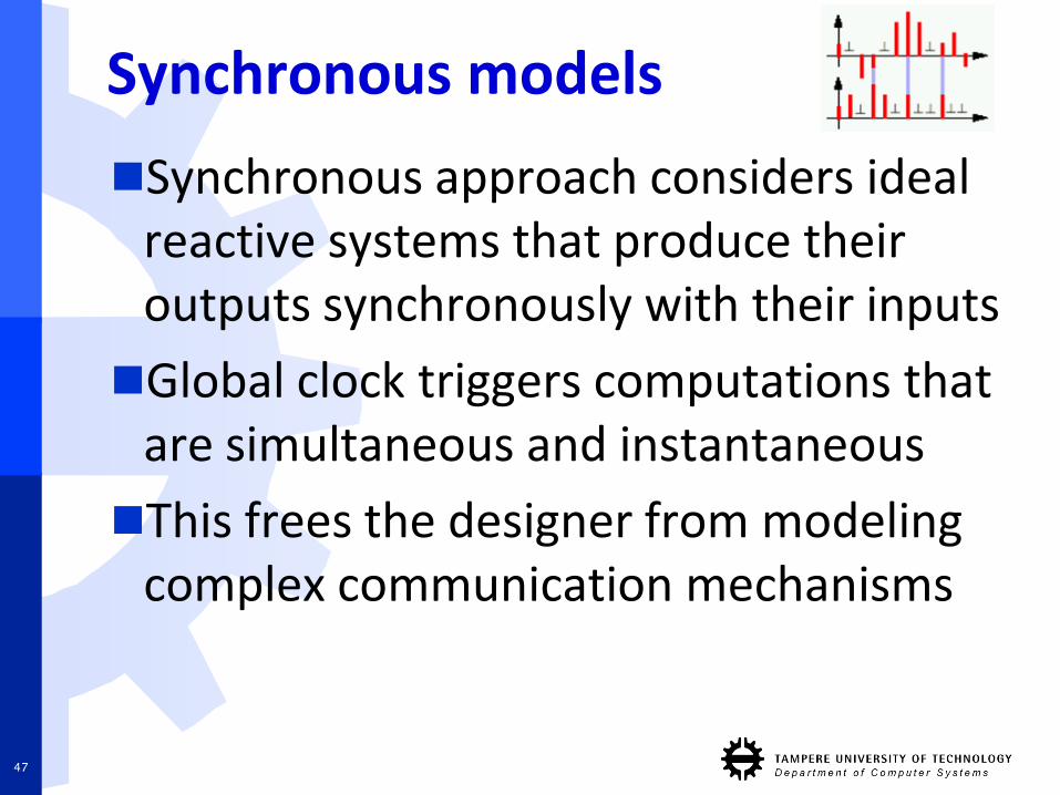
Synchronous approach considers ideal reactive systems that produce their outputs synchronously with their inputs
Global clock triggers computations that are simultaneous and instantaneous
This frees the designer from modeling complex communication mechanisms
47
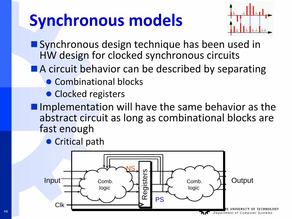
Synchronous modelsSynchronous design technique has been used in
HW design for clocked synchronous circuitsA circuit behavior can be described by separating
Combinational blocks Clocked registers
Implementation will have the same behavior as the abstract circuit as long as combinational blocks arefast enough Critical path
Input
Clk
...Comb.
logic
Output
NS
PSRe
gis
ters
Comb.
logic
48
Untimed models
Adopts the simplest timing modelProcesses are combined together with signals
carrying events which do not carry timing informationHowever, signals still preserve the order of
the emitted events; that is, events that are emitted first by the sender are received firstTheoretically this means that the time interval
between two consecutive events on a signal can vary from the positive limit of zero to infinity
49
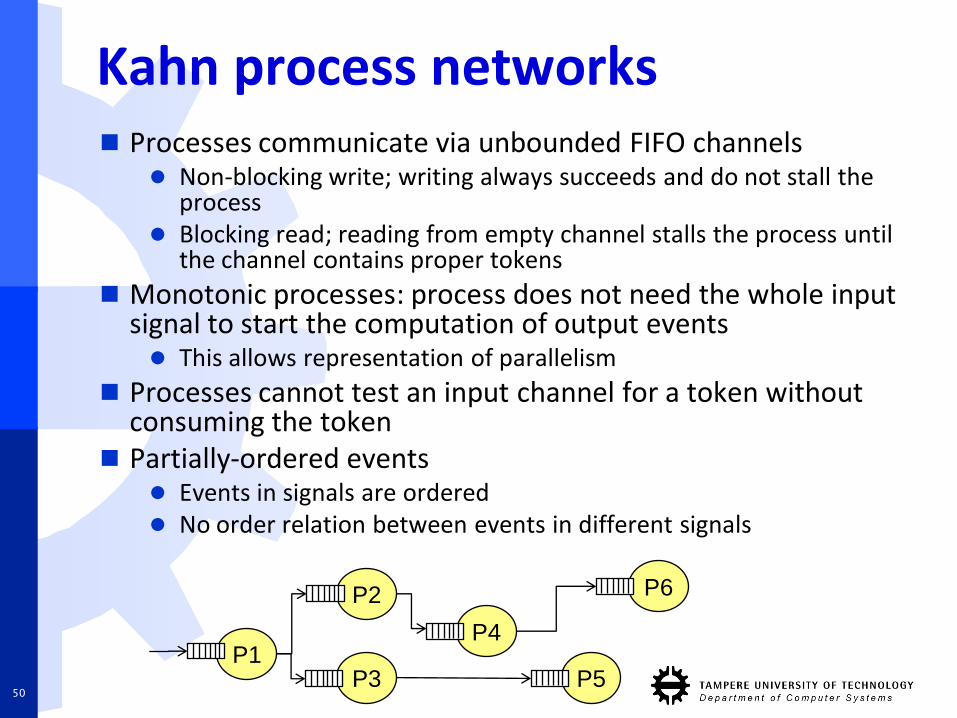
Kahn process networks Processes communicate via unbounded FIFO channels
Non-blocking write; writing always succeeds and do not stall the process
Blocking read; reading from empty channel stalls the process untilthe channel contains proper tokens
Monotonic processes: process does not need the whole input signal to start the computation of output events This allows representation of parallelism
Processes cannot test an input channel for a token withoutconsuming the token
Partially-ordered events Events in signals are ordered No order relation between events in different signals
P1
P2
P3
P4
P5
P6
50
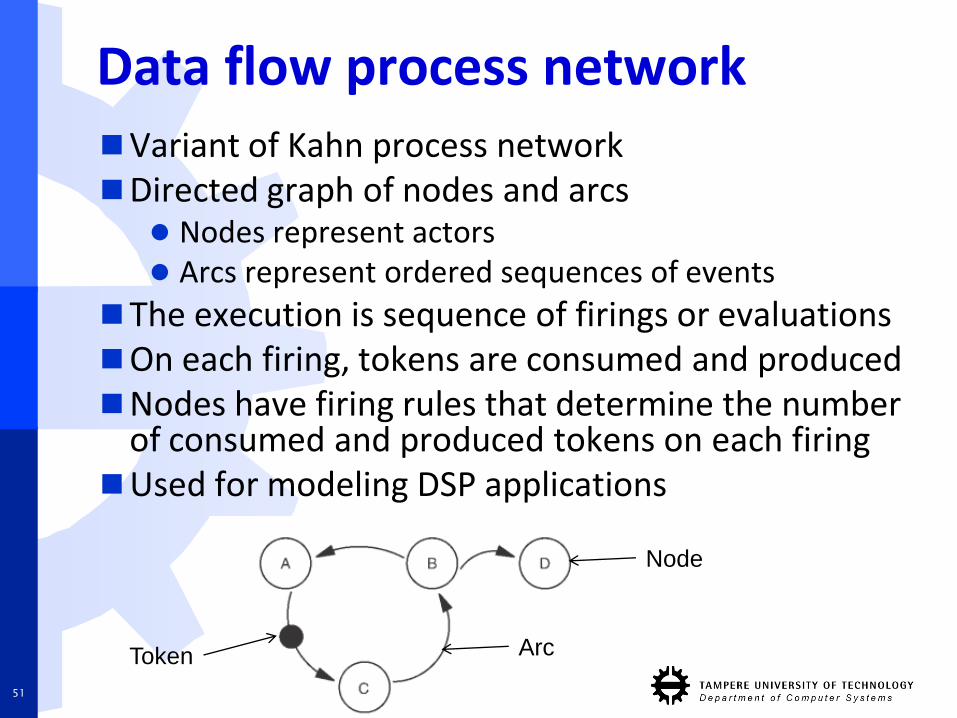
Data flow process networkVariant of Kahn process networkDirected graph of nodes and arcs
Nodes represent actors Arcs represent ordered sequences of events
The execution is sequence of firings or evaluationsOn each firing, tokens are consumed and producedNodes have firing rules that determine the number
of consumed and produced tokens on each firingUsed for modeling DSP applications
Node
ArcToken
51
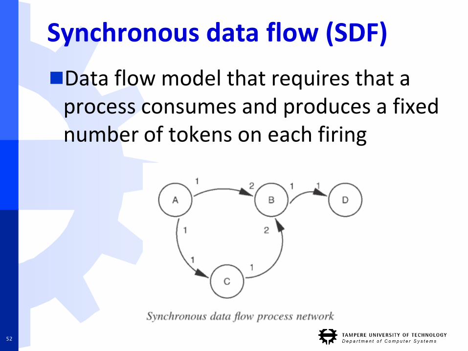
Synchronous data flow (SDF)
Data flow model that requires that a process consumes and produces a fixed number of tokens on each firing
52
Communication abstractionand semantics
53
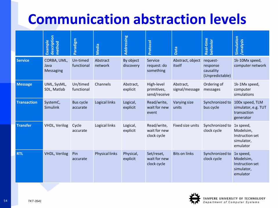
Communication abstraction levels
TKT-354154
Exam
ple
de
scri
pti
on
m
eth
od
Par
adig
m
Me
dia
Ad
dre
ssin
g
Pro
toco
l
Dat
a
Re
al-t
ime
b
eh
avio
r
Sim
ula
tio
n
/an
alys
is
Service CORBA, UML, Java Messaging
Un-timed functional
Abstract network
By object discovery
Servicerequest: do something
Abstract, object itself
request-responsecausality (Unpredictable)
1k-10Mx speed, computer network
Message UML, SysML, SDL, Matlab
Un/timedfunctional
Channels Abstract, explicit
High-level primitives, send/receive
Abstract,signal/message
Ordering of messages
1k-1Mx speed, computer simulations
Transaction SystemC, Simulink
Bus cycle accurate
Logical links Logical, explicit
Read/write, wait for new event
Varying size units
Synchronized to bus cycle
100x speed, TLM simulator, e.g. TUT transaction generator
Transfer VHDL, Verilog Cycle accurate
Logical links Logical, explicit
Read/write, wait for new clock cycle
Fixed size units Synchronized to clock cycle
1x speed, Modelsim, Instruction set simulator, emulator
RTL VHDL, Verilog Pin accurate
Physical links Physical, explicit
Set/reset, wait for new clock cycle
Bits on links Synchronized to clock cycle
1x speed, Modelsim, Instruction set simulator, emulator
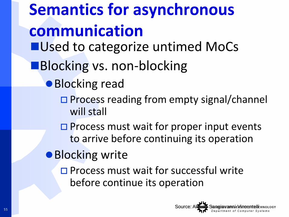
Semantics for asynchronous communicationUsed to categorize untimed MoCs
Blocking vs. non-blockingBlocking read
Process reading from empty signal/channelwill stall
Process must wait for proper input events to arrive before continuing its operation
Blocking write Process must wait for successful write
before continue its operation
Source: Alberto Sangiovanni-Vincentelli55
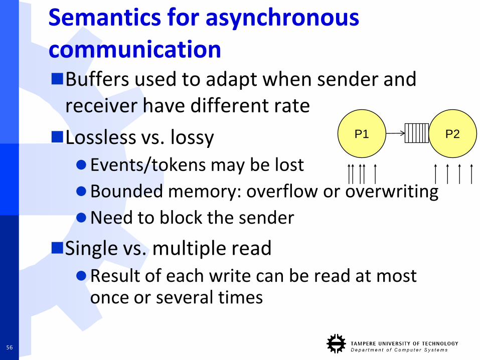
Semantics for asynchronous communicationBuffers used to adapt when sender and
receiver have different rate
Lossless vs. lossyEvents/tokens may be lost
Bounded memory: overflow or overwriting
Need to block the sender
Single vs. multiple readResult of each write can be read at most
once or several times
P1 P2
56
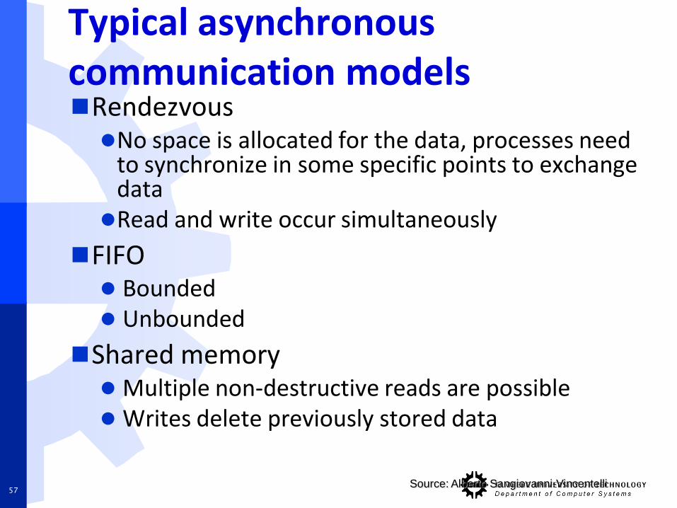
Typical asynchronous communication modelsRendezvousNo space is allocated for the data, processes need
to synchronize in some specific points to exchange dataRead and write occur simultaneously
FIFO Bounded Unbounded
Shared memory Multiple non-destructive reads are possible Writes delete previously stored data
Source: Alberto Sangiovanni-Vincentelli57
Example: Performance evaluation of embedded streaming applications withsystem-level simulation
58
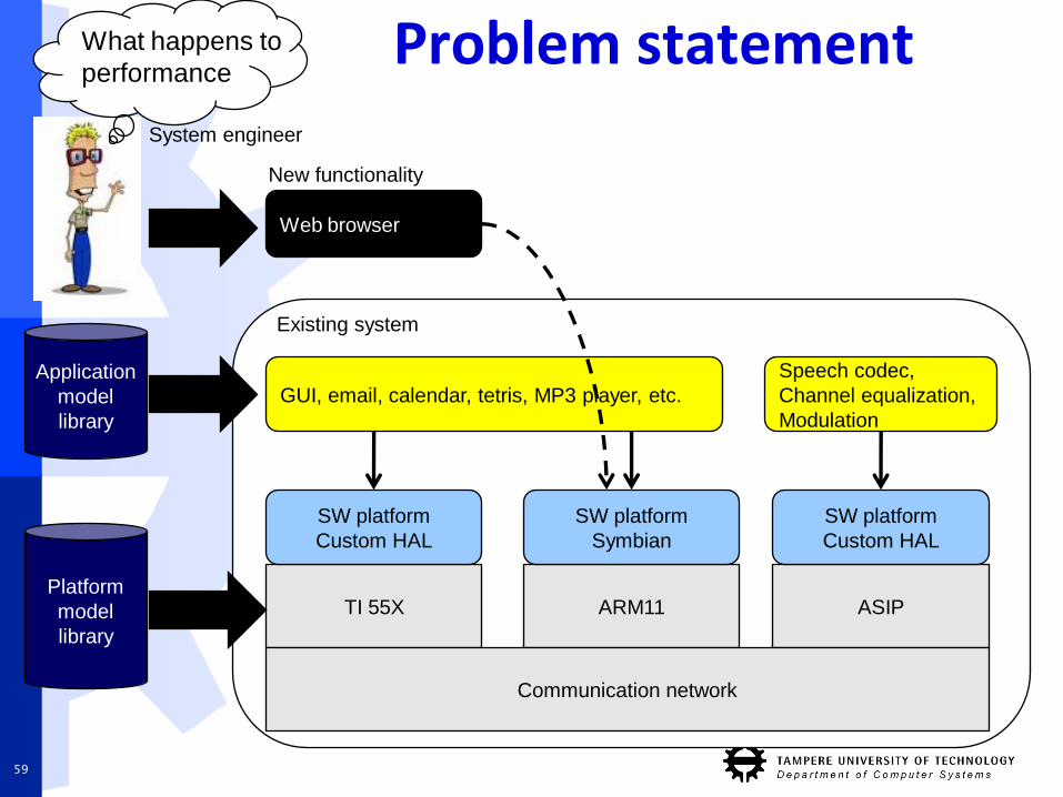
Problem statement
59
GUI, email, calendar, tetris, MP3 player, etc.
TI 55X
Speech codec,
Channel equalization,
Modulation
Platform
model
library
ARM11 ASIP
SW platform
Custom HAL
SW platform
Symbian
SW platform
Custom HAL
Web browser
Application
model
library
Communication network
System engineer
Existing system
New functionality
What happens to
performance
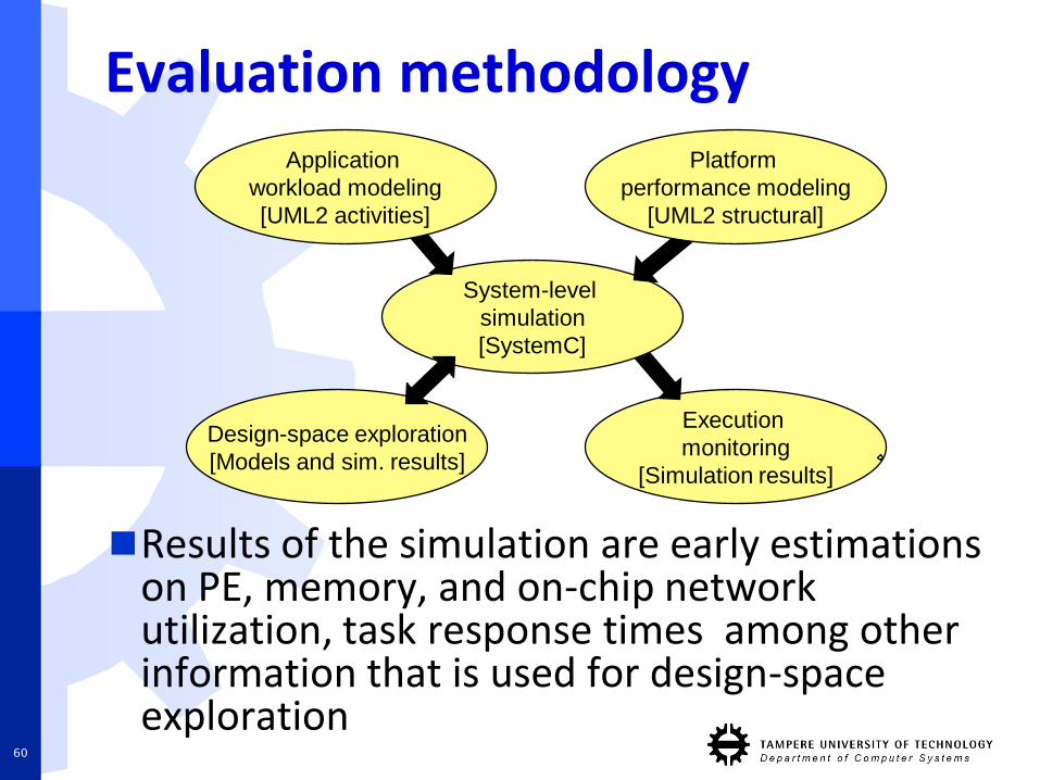
Evaluation methodology
Execution
monitoring
[Simulation results]
Design-space exploration
[Models and sim. results]
System-level
simulation
[SystemC]
Application
workload modeling
[UML2 activities]
Platform
performance modeling
[UML2 structural]
Results of the simulation are early estimations on PE, memory, and on-chip network utilization, task response times among other information that is used for design-space exploration
60
Model of ComputationApplication MoC
resembles Kahn processnetworkApplication tasks are
mapped onto platformresourcesPlatform resources
schedule and executetasksNo detailed behavior of
task is required, onlytheir workloadcharacteristics (operationcounts)
Τc
Τc
Τc
Τc
Τc
Τc
Ap
plicatio
n
pe1 pe2 pe3
Co
mp
utatio
nC
om
mu
-n
ication
HW
platfo
rm
δ0
δ1
δ2
δ4
δ5
δ3
e0
e1
0
1 3
2
4 5
se1
ce1
61
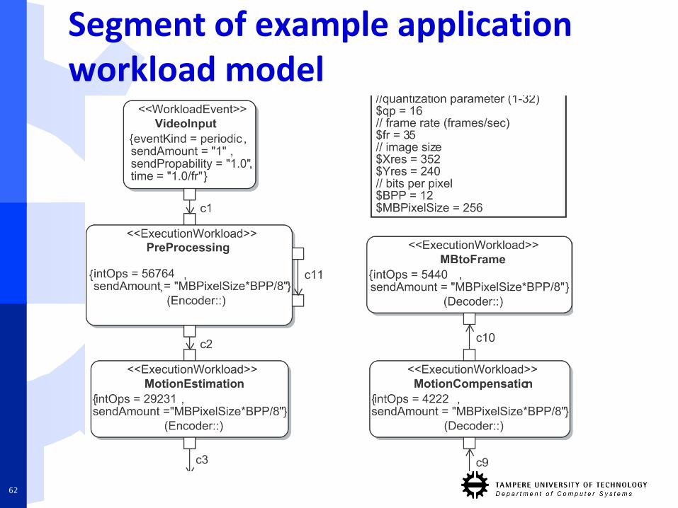
Segment of example applicationworkload model
62
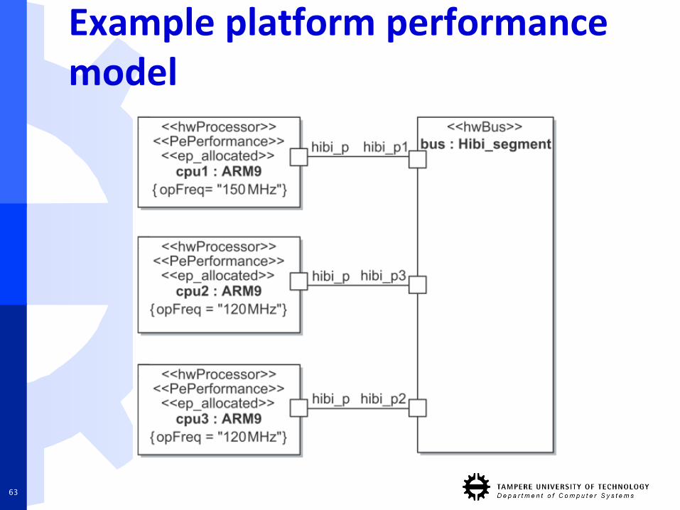
Example platform performance model
63
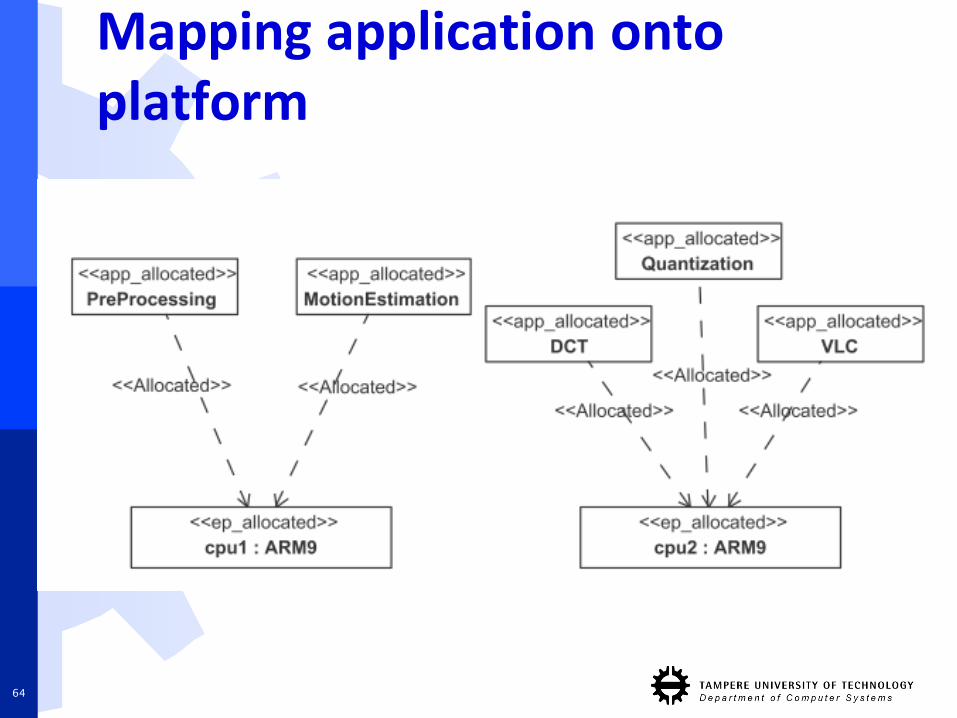
Mapping application onto platform
64
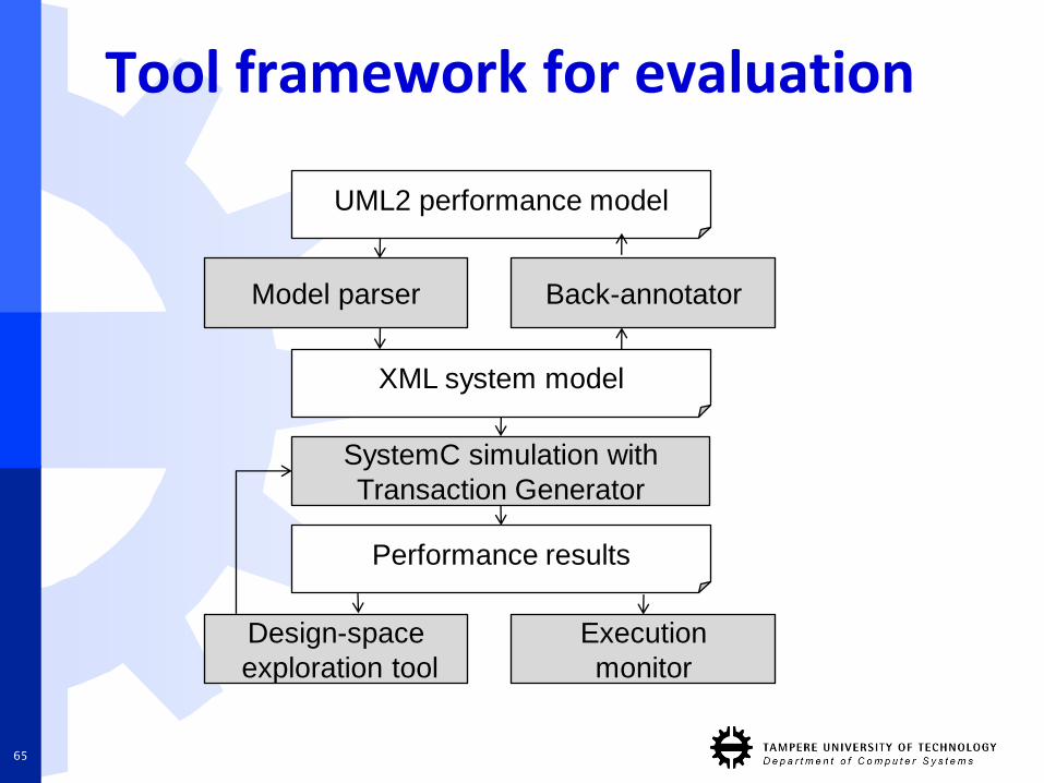
Tool framework for evaluation
UML2 performance model
Performance results
SystemC simulation with
Transaction Generator
XML system model
Design-space
exploration tool
Execution
monitor
Model parser Back-annotator
65
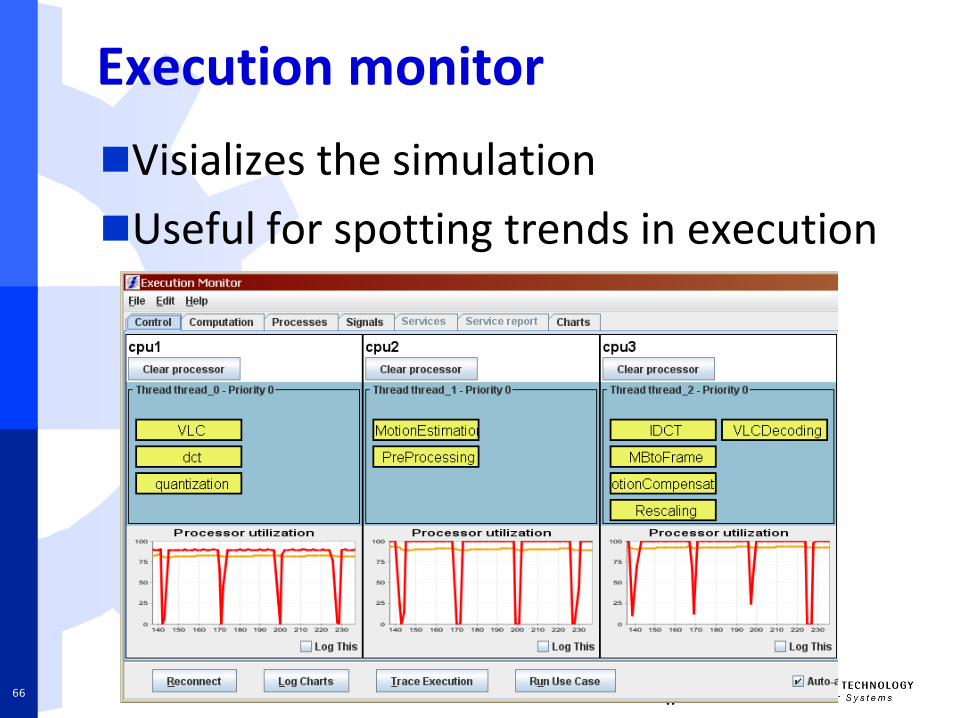
Execution monitor
Visializes the simulation
Useful for spotting trends in execution
66
Conclusions
67
Conclusions
Modeling allows validation of system using high level of abstraction prior to implementation
Time and effort is saved
Good model is abstract, understandable, accurate, predictable, inexpensive
MoCs can be categorized according to their
Notion of time
Communication semantics
68