Embed Size (px)
Citation preview

Introduction to SolidWorks
Draft 124
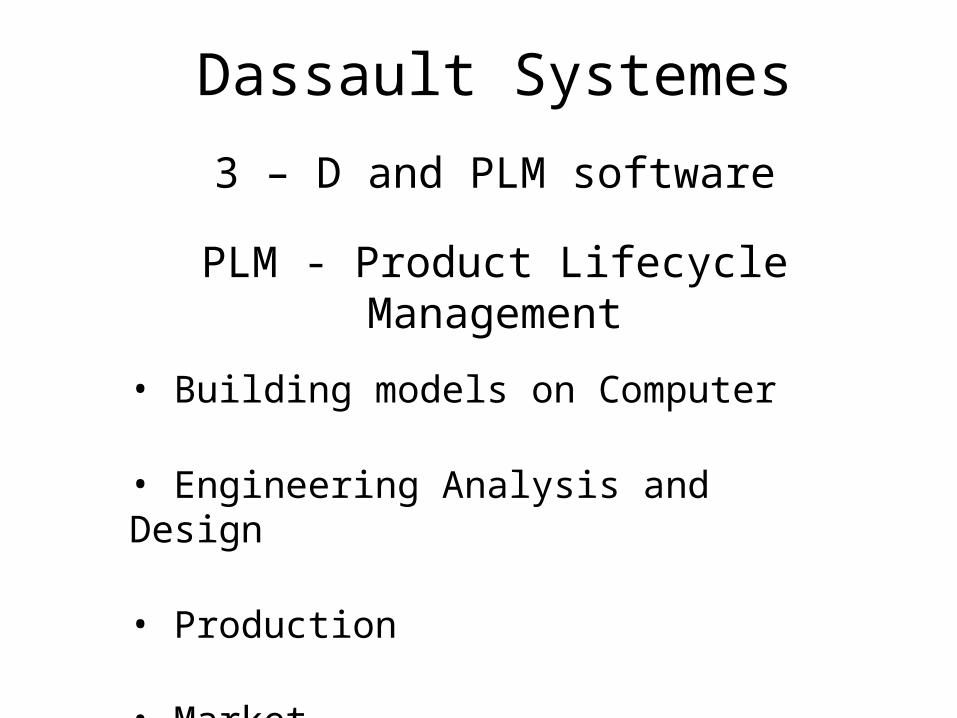
Dassault Systemes
3 – D and PLM software
PLM - Product Lifecycle Management
• Building models on Computer
• Engineering Analysis and Design
• Production
• Market.

SOLIDWORKSStarted in 1993
3D CAD : Creating complex parts and assemblies
2D Drawings : Working drawings for production
Modeling tools : Feature Recognition, Reverse Engineering
Data Management
Simulation
Presentation : Photoworks
Draft 124
• Understand and implement principles of Technical Drawing to create 3D parts, assemblies and 2D working drawings on the computer.
• Learn to use various capabilities of the software SolidWorks to create 3D parts, assemblies and 2D drawings.

SW Community forums.http://forum.solidworks.com
Blogs.blogs.solidworks.com
You tube
Online Resources

Dimensioning Revisited
Chapter 9

Understanding Dimensioning
• Drawings for products must be dimensioned so that production personnel all over the world can make mating parts that will fit properly when assembled or when used to replace parts
• Dimensions are given in the form of distances, angles, and notes regardless of the dimensioning units being used

Aspects of Good Dimensioning• The ability to create good dimensions requires:
– Technique of dimensioning
– Placement of dimensions manufacturing, measurement, inspection,
functioning.
– Choice of dimensions

Using Dimension and Extension Lines

Using Dimension and Extension Lines

Using Dimension and Extension Lines
• Dimensions should be lined up and grouped together as much as possible

Using Dimension and Extension Lines
• When extension lines or center lines cross visible object lines, gaps should not be left in the lines

Leaders• A leader is a thin solid line directing attention
to a note or dimension and starting with an arrowhead or dot
• Leaders should be at an angle of 30-60˚

Placing Dimensions
• Never letter a dimension value over any line on the drawing
• In a group of parallel dimension lines, the dimension values should be staggered
• Do not crowd dimension figures into limited spaces making them illegible

Placing Dimensions
• Place dimensions between views when possible, but only attached to a single view
• Dimensions should not be placed on a view unless doing so promotes the clarity of the drawing

Placing Dimensions
• When a dimension must be placed in a hatched area or on the view, leave an opening in the hatching or a break in the lines for the dimension value

Placing Dimensions
• Avoid dimensioning to hidden lines• Do not attach dimensions to visible lines
where the meaning is not clear• Notes for holes are usually placed where you
see the circular shape of the hole– An external cylindrical shape is dimensioned
where it appears rectangular

Placing Dimensions
• Give dimensions where the contours of the object are defined

Superfluous Dimensions
• All necessary dimensions must be shown but avoid giving unnecessary dimensions
• Do not repeat dimensions on the same view or on different views, or give the same information two different ways

Dimensioning Angles
• You should dimension angles by specifying the angle in degrees and a linear dimension

Dimensioning Arcs
• A circular arc is dimensioned in the view where you see its true shape by giving the value for its radius preceded by the abbreviation R
Fillets and Rounds
• Individual fillets and rounds are dimensioned like other arcs– If there are only a few and they are obviously the
same size, giving one typical radius is preferred– Fillets radii can also be given in a general note

Size Dimensions: Holes

Dimension Symbols

Dimensioning Rounded-end Shapes

Dimensioning Threads

Dimensioning Chamfers

Location Dimensions

Location Dimensions

Mating Dimensions

Which is the mating dimension in figure (a)
Which is the mating dimension in figure (b)

Notes
• It is usually necessary to supplement the direct dimensions with notes
• Notes should be worded to allow only one interpretation
• Notes should be lettered horizontally

Tabular DimensionsSeveral parts with Similar features Different dimensions.

Coordinate Dimensioning

Coordinate Dimensioning

Dimensioning Examples