Embed Size (px)
Citation preview

Introduction to the TASKINGSoftware Platform for ARM
MA101-869 (v1.2) October 10, 2014

Copyright © 2014 Altium BV.
All rights reserved.You are permitted to print this document provided that (1) the use of such is for personal use onlyand will not be copied or posted on any network computer or broadcast in any media, and (2) no modifications of thedocument is made. Unauthorized duplication, in whole or part, of this document by any means, mechanical or electronic,including translation into another language, except for brief excerpts in published reviews, is prohibited without theexpress written permission of Altium BV. Unauthorized duplication of this work may also be prohibited by local statute.Violators may be subject to both criminal and civil penalties, including fines and/or imprisonment. Altium, TASKING,and their respective logos are trademarks or registered trademarks of Altium Limited or its subsidiaries. All otherregistered or unregistered trademarks referenced herein are the property of their respective owners and no trademarkrights to the same are claimed.

Table of Contents1. Introduction .................................................................................................................. 12. Organization of the Software Platform Repositories ............................................................... 3
2.1. Device Stacks ..................................................................................................... 32.1.1. Peripherals .............................................................................................. 42.1.2. Drivers .................................................................................................... 42.1.3. Stack Services ......................................................................................... 52.1.4. Adaptors ................................................................................................. 5
2.2. Software Services ............................................................................................... 63. Getting Started with the Software Platform Builder ................................................................ 7
3.1. Creating a Software Platform Document ................................................................... 73.2. Working with Device Stacks ................................................................................... 83.3. Configuring the Software Platform Plug-ins ............................................................. 123.4. Generating and Using the Source Code ................................................................. 133.5. Using the Sample Projects .................................................................................. 153.6. API Reference .................................................................................................. 173.7. Software Platform Builder Preferences ................................................................... 17
4. Tutorial Creating a File System on a RAM Disk ................................................................... 194.1. Create a Project ................................................................................................ 194.2. Add a Software Platform Document ....................................................................... 204.3. Add the Services and Device Stacks ...................................................................... 214.4. Configure the Software Platform Plug-ins ................................................................ 244.5. Generate the Source Code .................................................................................. 254.6. Write and Build the Application ............................................................................. 264.7. Debug the Application ......................................................................................... 29
5. Tutorial Using a Library Wrapper ...................................................................................... 315.1. Create a Project ................................................................................................ 315.2. Add a Software Platform Document ....................................................................... 325.3. Add the Services and Device Stacks ...................................................................... 335.4. Configure the Software Platform Plug-ins ................................................................ 355.5. Generate the Source Code .................................................................................. 365.6. Configure the Pins ............................................................................................. 375.7. Write and Build the Application ............................................................................. 385.8. Connect the Board ............................................................................................. 395.9. Debug the Application ......................................................................................... 40
6. Tutorial Creating a Local Repository ................................................................................. 436.1. Create a Local Repository Project ......................................................................... 436.2. Add a Software Platform Plug-in ........................................................................... 436.3. Modify the Software Platform Plug-in ..................................................................... 446.4. Use the Local Repository .................................................................................... 45
7. Content of the Default ARM Repositories .......................................................................... 497.1. TASKING POSIX Repository ................................................................................ 497.2. STM32 Repository ............................................................................................. 507.3. EFM32 Repository ............................................................................................. 517.4. Generic Repository ............................................................................................ 51
8. Glossary .................................................................................................................... 57
iii

iv
Introduction to the TASKING Software Platform for ARM
Chapter 1. IntroductionWith TASKING Software Platform you can quickly create full-featured applications. A Software Platformis made up of software blocks, pieces of functionality that you can use in your application, like RTOSfacilities, peripheral access or software protocols. The exact contents of a Software Platform depend onthe need of your application.
The Software Platform Builder is used to manage your Software Platform. It is both a graphical editor anda code generator. Collections of software modules are delivered as Software Platform repositories.
The following figure shows the process to create your own Software Platform:
A Software Platform repository may contain any kind of software, but typical modules include interruptservices, timers, peripherals (hardware wrappers), drivers, kernel services (such as POSIX multithreading),device I/O, file system (FatFs), networking (TCP/IP), graphical user interface, etc.
The main reasons for having software modules are:
• Integration. Modules do not live isolated. Quite the contrary, they need to relate and interact with othermodules. For instance, they often define interfaces which are implemented by other modules.
• Software reuse. Software reuse means effectively to be capable of encapsulating all the informationof a component (hardware and/or software) in a consistent manner. Once this information is made
1
available, higher abstraction layers can use it to customize or configure the system after little (or none)user intervention.
• Hide complexity. Writing software from scratch is a time-consuming activity. To write software thataccesses or controls a peripheral, you need a thorough knowledge of how the peripheral works: whichregisters you need, which device specific commands to use, which communication protocols to use,and which interrupts to handle.
The modules of the Software Platform repository take care of all these laborious lower level routinesand instead provide you with an easy to use Application Programming Interface (API) for each peripheralthat your application needs to control.
• Configurability. Embedded systems require very precise (compile-time) configuration mechanisms tomanage their intrinsic complexity. A typical module may show different possible configurations thathave direct impact on the final behavior of the software.The main idea behind compile-time configurationsin embedded systems is to remove unnecessary functionality in order to enhance memory costs andreal-time performance.
• Expandability. Altium, but also other parties, can adapt the modules and create their own modules.
For information how to use the Software Platform Builder, see Chapter 3, Getting Started with the SoftwarePlatform Builder.
2
Introduction to the TASKING Software Platform for ARM

Chapter 2. Organization of the SoftwarePlatform RepositoriesSoftware Platform repositories can contain numerous software modules that take care of lower levelsoftware routines as well as modules that offer extra functionality by providing you with a convenient API.
The Software Platform consists of device stacks and software services.This chapter describes both partsand how they are related.
2.1. Device Stacks
Device stacks are all about making hardware peripherals available to application code through abstractand generic software interfaces. By placing more or less modules on a stack, you can choose theabstraction level you want to use in your application.The lowest level modules are specific for a particularhardware device. On top of that, you can stack higher level modules that provide more generic functionalityto access the device. For example, at the higher, abstract level, you could choose to use a module toaccess a file system in your application. At the lower levels you still can select modules to decide whichspecific storage device you want to access (a hard drive, SD card, RAM drive, ...) Thus, the lower levelmodules are more specific for a particular peripheral while the higher level modules are less hardwarespecific and can even be used in combination with multiple peripheral devices.
You can use the Software Platform Builder editor to build device stacks.
Example
The following figure contains a HTTP device stack and a GUI device stack.
3

Each colored stack item represents a software module. In this example the HTTP stack consists of fivemodules, for each abstraction level one. The GUI Services requires Graphics Services and PointerServices. In general, your application interfaces only to the highest level modules.
Device stacks may be composed of the following types of plug-ins: peripherals, drivers, stack servicesand adaptors.
2.1.1. Peripherals
Peripherals (the green stack items) are the lowest level modules. They provide information for the higherlayers of the stack to access the peripherals. Information such as the base address, interrupt assignmentand any soft peripheral configuration is all stored in the peripheral.
Peripheral modules are meant to be instantiated. Each instance then corresponds to one device of thegiven kind. Instances of peripherals do not normally require other instances.
In most situations, your application does not access the peripherals directly, because the applicationaccesses them through the driver's interface on top of it.
For most peripherals you need to use the TASKING Pin Mapper to configure the connections betweenperipherals and port pins. For information about the TASKING Pin Mapper see Using the TASKING PinMapper for ARM.
2.1.2. Drivers
Drivers (the yellow stack items) provide the next level of abstraction. They provide low-level access tospecific hardware either via a peripheral or via another driver.
The difference between a driver and a peripheral is well defined. The peripheral only defines basicinformation about the hardware but provides no further functionality. This basic information can be usedby a driver which you can place on top of the peripheral.
Driver modules are meant to be instantiated. Each instance then corresponds to one device of the givenkind. A driver instance requires one instance of the corresponding peripheral.
Drivers are hardware specific and so are the interfaces they offer. Hence, if your application containscode that accesses a driver's API, your application will be hardware dependent. Drivers still operate at alow abstraction level, and using a device at the driver level requires knowledge of that particular driver'sinterface.
4
Introduction to the TASKING Software Platform for ARM

Some drivers are available as library wrappers. They only offer an initialization routine which you can callfrom an application in order to configure pins, clocks and registers. After this initialization you can usethe peripheral driver libraries from silicon vendors.
2.1.3. Stack Services
Stack services (the blue stack items) are the most abstract layers of functionality.
Stack services provide standardized, hardware independent access to devices. Stack services areinstantiated and ensure portability of your application. For example, if you run an application with a genericTCP/IP service, the application remains the same if you replace Ethernet with PPP and serial. A portableTCP/IP application works exactly the same, whether linked to a UART or a to an EMAC peripheral, sincethe Software Platform handles the lower level details.
2.1.4. Adaptors
Adaptors (the grayed out stack items) provide a mechanism to link higher level services to hardwarespecific modules.
Adaptors do not have options you can change. By default, adaptors are not visible in the device stacks.
You can make adaptors visible in the Preferences dialog. See Section 3.7, Software Platform BuilderPreferences.
5
Organization of the Software Platform Repositories
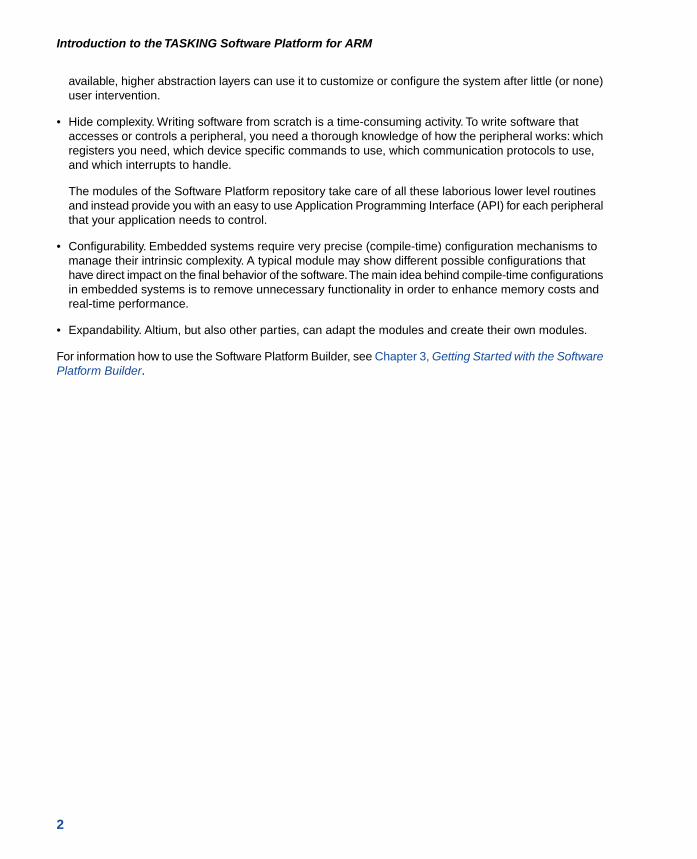
2.2. Software Services
Some services are static and not meant to be instantiated. They have no (direct) relationship withperipherals or other services. They facilitate common functionality, like POSIX multithreading support.They are shown in your editor at the left side of the Device Stacks. Those services may also be addedautomatically if required by other services.
6
Introduction to the TASKING Software Platform for ARM
Chapter 3. Getting Started with the SoftwarePlatform BuilderThe Software Platform Builder is the graphical interface to manage the plug-ins of the Software Platformrepositories. The Software Platform Builder enables you to:
• add peripherals
• build device stacks
• add software services
• configure all software services and stack items
• generate code for your Software Platform
3.1. Creating a Software Platform Document
To use the Software Platform Builder you need a project.The Software Platform Builder becomes availablewhen you add a special Software Platform document to your project.
Add a Software Platform document to an existing project
1. First make sure you have an existing project. This is explained in the Getting Started manual of thetoolset. In this example we assume you have a project called myproject.
2. From the File menu, select New » TASKING Software Platform Document.
The New Software Platform Document wizard appears.
3. Select the Project folder for the Software Platform document: type the name of your project(myproject) or click the Browse button to select a project.
4. In the File name field, enter a name for the Software Platform document, for examplemyproject.swpxmi and click Finish.
A new Software Platform document is added to the project with extension .swpxmi.
TASKING Software Platform Builder editor
Double-click on the Software Platform document to open it. The editor consists of two sections: theSoftware Services and the Device Stacks.
7

The following toolbar icons are available:
DescriptionActionIcon
Generates the source code and adds it to your project.Generate Code
Adds software services and/or device stacks.Add
Reloads the repository. This can be necessary when you have updatedthe repository or when you changed the contents of a local repository.
Reload Repository
3.2. Working with Device Stacks
In the Device Stacks section you can build device stacks by adding modules from one or more SoftwarePlatform repositories. To build a device stack, you can start bottom-up by choosing a peripheral or youcan start top-down by choosing a high-level stack service.
Add a software service or device stack
1. From the Software Platform menu, select Add... or click .
The Add Software Services and Device Stacks dialog appears.The left side shows the stack services,software services and drivers. The right side shows all peripherals for the selected device.You canfilter on a specific repository. By default all available repositories are listed.
8
Introduction to the TASKING Software Platform for ARM

2. (Optional) Select a Repository.
3. Select the services, drivers and peripherals you want and click OK.
The new device stacks and software services appear in the TASKING Software Platform editor.Some software services appear automatically because they are required by other services or stackitems.
If you do not see any peripheral, you probably selected an unsupported device or a genericarchitecture.
9
Getting Started with the Software Platform Builder
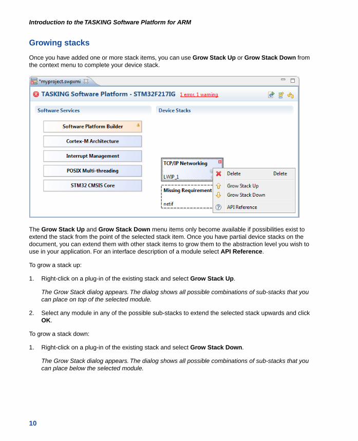
Growing stacks
Once you have added one or more stack items, you can use Grow Stack Up or Grow Stack Down fromthe context menu to complete your device stack.
The Grow Stack Up and Grow Stack Down menu items only become available if possibilities exist toextend the stack from the point of the selected stack item. Once you have partial device stacks on thedocument, you can extend them with other stack items to grow them to the abstraction level you wish touse in your application. For an interface description of a module select API Reference.
To grow a stack up:
1. Right-click on a plug-in of the existing stack and select Grow Stack Up.
The Grow Stack dialog appears. The dialog shows all possible combinations of sub-stacks that youcan place on top of the selected module.
2. Select any module in any of the possible sub-stacks to extend the selected stack upwards and clickOK.
To grow a stack down:
1. Right-click on a plug-in of the existing stack and select Grow Stack Down.
The Grow Stack dialog appears. The dialog shows all possible combinations of sub-stacks that youcan place below the selected module.
10
Introduction to the TASKING Software Platform for ARM

2. Select any module in any of the possible sub-stacks to extend the selected stack downwards andclick OK.
Note that when you click on a Missing Requirement, the Grow Stack dialog appears automatically.
The Grow Stack dialog contains two tabs, one to form a new stack and one to link two existing stacks. Ifyour document contains partial stacks which potentially can be combined into a single stack, it will bevisible in the Link to Existing tab.You can link them together to form a complete stack. Otherwise selectthe New Stacks tab.
Example
The following figure shows some device stacks.
11
Getting Started with the Software Platform Builder

Note that some drivers (ILI9320 LCD Module Driver in this example) do not require a peripheral, becausethe device is accessed through the memory controller.
3.3. Configuring the Software Platform Plug-ins
You can configure peripherals, drivers, stack services and software services. Stack items can haveindividual options and/or global options. Individual options are only valid for a specific stack item, globaloptions are valid for all stack items of the same type. When you click on an item in the Software PlatformBuilder, configuration options appear in the Properties view.
For example, when you click HyperText Transfer Protocol, a view similar to the following appears:
A plug-in option may automatically set other plug-in options and may even add automatic services. Forexample, in this case when you set HTTPS to true this adds the Matrix SSL / TLS services automatically.
12
Introduction to the TASKING Software Platform for ARM
Connecting peripherals to pins
For most peripherals you need to specify which pins are used.You can do this with the TASKING PinMapper.
1. Add a TASKING Pin Mapper Document (File » New » TASKING Pin Mapper Document) andconfigure the pins as explained in Using the TASKING Pin Mapper for ARM.
This results in a file called myproject.pincfg.
2. From the Pin Mapper menu, select Generate Code or click .
The Pin Mapper sources are generated and are added to your project in the folder PinMapper.
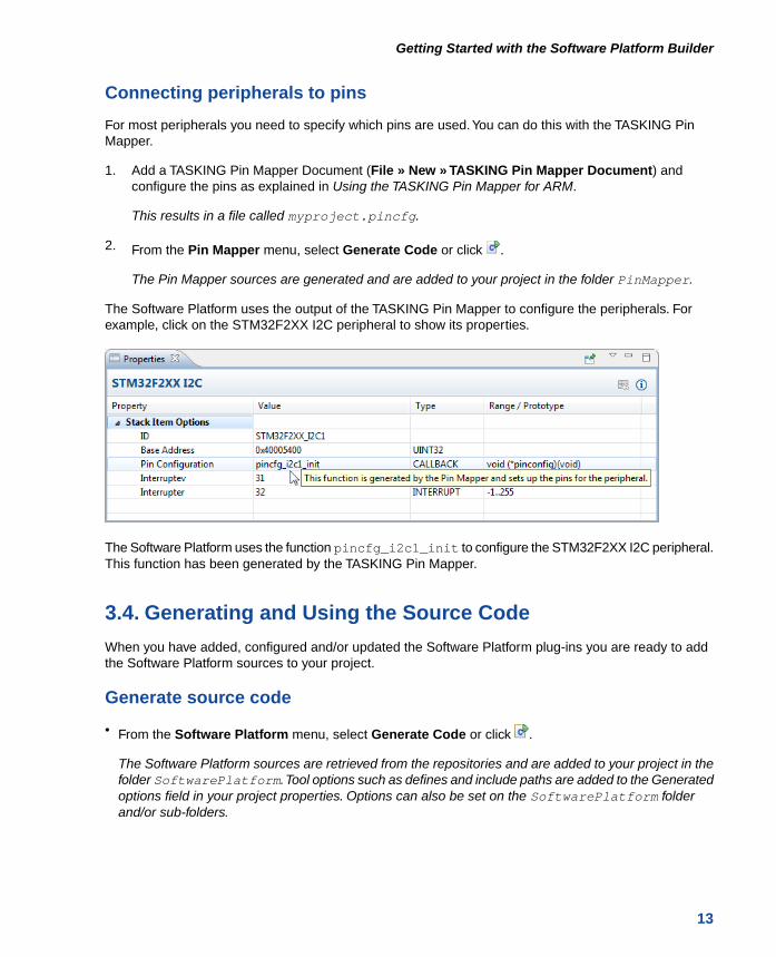
The Software Platform uses the output of the TASKING Pin Mapper to configure the peripherals. Forexample, click on the STM32F2XX I2C peripheral to show its properties.
The Software Platform uses the function pincfg_i2c1_init to configure the STM32F2XX I2C peripheral.This function has been generated by the TASKING Pin Mapper.
3.4. Generating and Using the Source Code
When you have added, configured and/or updated the Software Platform plug-ins you are ready to addthe Software Platform sources to your project.
Generate source code
• From the Software Platform menu, select Generate Code or click .
The Software Platform sources are retrieved from the repositories and are added to your project in thefolder SoftwarePlatform.Tool options such as defines and include paths are added to the Generatedoptions field in your project properties. Options can also be set on the SoftwarePlatform folderand/or sub-folders.
13
Getting Started with the Software Platform Builder

Using the Software Platform sources
A plug-in defines a set of functionality - that is, types, defines, structures and functions. This functionalityis accessible from your application.You can find the generated files in the SoftwarePlatform folderof your project.To use the generated files, you must add a #include statement into your top-level sourcefile (typically main.c):
#include "swplatform.h"
All other required header files needed to access the devices in the stack are included (made available)as a result of including this file.
14
Introduction to the TASKING Software Platform for ARM

The following is an example of swplatform.h generated as a 'wrapper' around the active project'sSoftware Platform:
You can now use the functions of the Software Platform in your sources. For example,
int main( void ){
http_t *http;
http = http_open(HTTP_1); if (!http) { fprintf(stderr,"HTTP open failed\n"); exit(1); } ...}
3.5. Using the Sample Projects
A Software Platform repository may contain a number of sample projects.These examples can be a goodstarting point for your own project.
You can import Software Platform repository examples via the Import wizard in Eclipse.
15
Getting Started with the Software Platform Builder
Import an existing Software Platform project
1. From the File menu, select Import.
The Import dialog appears.
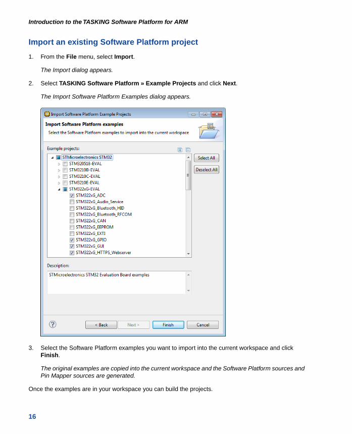
2. Select TASKING Software Platform » Example Projects and click Next.
The Import Software Platform Examples dialog appears.
3. Select the Software Platform examples you want to import into the current workspace and clickFinish.
The original examples are copied into the current workspace and the Software Platform sources andPin Mapper sources are generated.
Once the examples are in your workspace you can build the projects.
16
Introduction to the TASKING Software Platform for ARM

3.6. API Reference
Each repository contains detailed descriptions of its contents.You can access this documentation fromthe Help menu (Help » Help Contents » Software Platform Repository Reference).
Accessing help on individual drivers or services
• Right-click on a stack item or a software service and select API Reference.
Help appears on the individual stack item.
3.7. Software Platform Builder Preferences
You can use the Preferences dialog in Eclipse to specify how the Software Platform Builder should operate.
To set preferences
1. From the Window menu, select Preferences.
The Preferences dialog appears.
2. Select TASKING » Software Platform Builder.
The Software Platform Builder page appears.
3. Set your preferences and click OK.
You can set the following preferences:
Generate code on save
By default the Software Platform Builders asks if you want to generate code when you save a document(Prompt).You can choose to do this automatically (Always) or Never.
17
Getting Started with the Software Platform Builder

Software Platform Editor
• Show adaptors and internal items. By default, adaptors (see Section 2.1.4, Adaptors) are not visiblein the device stacks.This option can be useful when you need support from Altium or when you developyour own plug-ins. Normally, you do not need this option.
Properties View
• Show resource info. By default, information about the resource is not visible in the Properties view.
You can use the Show Resource Info button ( ) in the Properties view to toggle the resourceinformation on or off, or you can use this preference option to turn resource information on by default.
• Show hidden options. By default, several plug-in options are not visible in the Properties view. Thisoption can be useful when you need support from Altium or when you develop your own plug-ins.Normally, you do not need this option.
18
Introduction to the TASKING Software Platform for ARM

Chapter 4.Tutorial Creating a File Systemon a RAM DiskIn this tutorial we show how to create an example Software Platform project.You will learn how to usethe software to create a file system on a RAM disk. This example uses the simulator, so no additionalhardware is required.
4.1. Create a Project
The first step is to create a C project. This is explained in detail in the Getting Started manual of thetoolset, but for this tutorial we repeat this step.
1. From the File menu, select New » TASKING ARM C/C++ Project
The New C/C++ Project wizard appears.
2. Enter a name for your project, for example Generic_FileSystem.
In the Location field you will see the location where the new project will be stored.
3. In the Project type box you can select whether to create an application or a library.
• Expand TASKING ARM Application and select Empty Project. This creates a project without aC source file.
• Click Next to continue.
The ARM Project Settings page appears.
19
4. Select the target processor core or architecture for which you want to build the application. Forexample, architecture ARMv7-M. Afterwards you can always change the processor in the Project »Properties for dialog.
5. Leave the rest of the dialog as is and click Next.
The Target Settings page appears.
6. In order to debug your project you need to create a debug configuration.
• Select a target.You can select a target board or a simulator. For this tutorial we select the ARMSimulator.
• Enable Add launch configuration to the project. This allows you to debug your project.
• Leave the other tabs as is. For more information, see section Creating a Customized DebugConfiguration in Chapter Using the Debugger of the TASKING VX-toolset for ARM User Guide.
7. Click Finish to finish the wizard and to create the project.
The project has now been created and is the active project.
4.2. Add a Software Platform Document
Now that we have a project we can add a Software Platform document.
1. From the File menu, select New » TASKING Software Platform Document.
The New Software Platform Document dialog appears.
2. Leave the project name and file name as is and click Finish.
A new Software Platform document is added to the active project (Generic_FileSystem.swpxmi).
TASKING Software Platform Builder editor
Double-click on the Software Platform document Generic_FileSystem.swpxmi to open it. The editorconsists of two sections: the Software Services and the Device Stacks.
20
Introduction to the TASKING Software Platform for ARM

4.3. Add the Services and Device Stacks
Now it is time to create our RAM disk and create a file system. What we need is a RAM disk, a storagesystem and terminal services for debugging.
Add a software service or device stack
1. From the Software Platform menu, select Add... or click .
The Add Software Services and Device Stacks dialog appears.The left side shows the stack services,software services and drivers. The right side shows all peripherals for the selected device. In thistutorial you do not see any peripheral, because we selected a generic architecture.
21
Tutorial Creating a File System on a RAM Disk

2. From the Repository, select TASKING POSIX implementation
Only services and drivers from the selected repository are shown.
3. From the Services and Drivers, select POSIX Debug Terminal and POSIX Storage System andclick OK.
The new device stacks and software services appear in the TASKING Software Platform editor.Some software services appear automatically because they are required by other services or stackitems.
22
Introduction to the TASKING Software Platform for ARM

As you can see we are missing a requirement. Block device I/O is needed for communication betweenthe RAM Disk and the Storage System. We will add this now.
1. Click on the Missing Requirement stack item.
The Grow Stack dialog appears. The dialog shows all possible combinations of sub-stacks that youcan place below the selected module.
2. We want to add a RAM Disk. To do this, in the New Stacks tab, click on RAM Disk to select it andclick OK.
23
Tutorial Creating a File System on a RAM Disk

Your Software Platform now looks like this:
4.4. Configure the Software Platform Plug-ins
You can configure peripherals, drivers, stack services and software services. Stack items can haveindividual options and/or global options. Individual options are only valid for a specific stack item, globaloptions are valid for all stack items of the same type. When you click on an item in the Software PlatformBuilder, configuration options appear in the Properties view.
In this tutorial we want to redirect Standard Output and Standard Error to the POSIX Debug Terminal.
1. Click on the POSIX Standard Device I/O software service.
A view similar to the following appears:
24
Introduction to the TASKING Software Platform for ARM

2. Change the value of Standard Output and Standard Error to true.
New properties for device name and buffer type appear. When you hover the mouse over a propertyballoon help appears.
3. Change the value of stdout device name and stderr device name to DBG_TERMINAL_1.This is the ID of the POSIX Debug Terminal stack item.
The properties for POSIX Standard Device I/O should now look like this:
4.5. Generate the Source Code
Now that you have added and configured the Software Platform plug-ins you are ready to generate theSoftware Platform sources for your project.
• From the Software Platform menu, select Generate Code or click .
The Software Platform sources are retrieved from the repositories and are added to your project in thefolder SoftwarePlatform.Tool options such as defines and include paths are added to the Generated
25
Tutorial Creating a File System on a RAM Disk
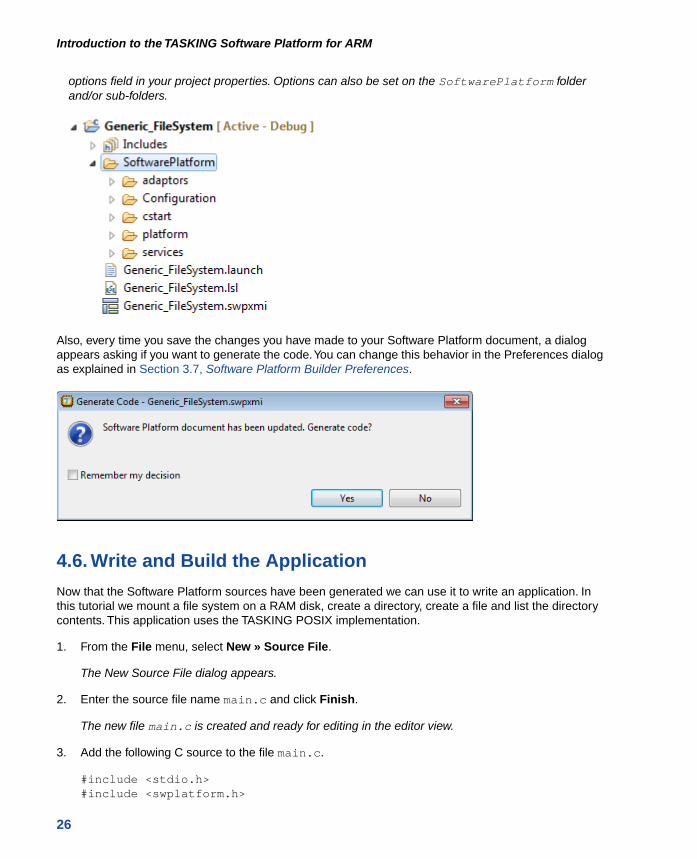
options field in your project properties. Options can also be set on the SoftwarePlatform folderand/or sub-folders.
Also, every time you save the changes you have made to your Software Platform document, a dialogappears asking if you want to generate the code.You can change this behavior in the Preferences dialogas explained in Section 3.7, Software Platform Builder Preferences.
4.6. Write and Build the Application
Now that the Software Platform sources have been generated we can use it to write an application. Inthis tutorial we mount a file system on a RAM disk, create a directory, create a file and list the directorycontents. This application uses the TASKING POSIX implementation.
1. From the File menu, select New » Source File.
The New Source File dialog appears.
2. Enter the source file name main.c and click Finish.
The new file main.c is created and ready for editing in the editor view.
3. Add the following C source to the file main.c.
#include <stdio.h>#include <swplatform.h>
26
Introduction to the TASKING Software Platform for ARM
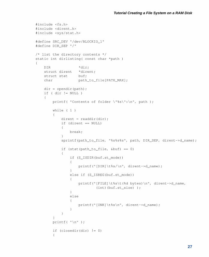
#include <fs.h>#include <dirent.h>#include <sys/stat.h>
#define SRC_DEV "/dev/BLOCKIO_1"#define DIR_SEP "/"
/* list the directory contents */static int dirlisting( const char *path ){ DIR *dir; struct dirent *dirent; struct stat buf; char path_to_file[PATH_MAX];
dir = opendir(path); if ( dir != NULL ) { printf( "Contents of folder \"%s\":\n", path );
while ( 1 ) { dirent = readdir(dir); if (dirent == NULL) { break; } sprintf(path_to_file, "%s%s%s", path, DIR_SEP, dirent->d_name);
if (stat(path_to_file, &buf) == 0) { if (S_ISDIR(buf.st_mode)) { printf("[DIR]\t%s/\n", dirent->d_name); } else if (S_ISREG(buf.st_mode)) { printf("[FILE]\t%s\t(%d bytes)\n", dirent->d_name, (int)(buf.st_size) ); } else { printf("[UNK]\t%s\n", dirent->d_name); } } } printf( "\n" );
if (closedir(dir) != 0) {
27
Tutorial Creating a File System on a RAM Disk

return -1; } return 0; } return -1;}
int main(void){ int rc;
/* Create the RAM disk */ rc = mkfs(SRC_DEV, "fatfs", 0, NULL /* "Ramdisk" */, false); if (rc < 0) { printf("Error: mkfs returned %d\n", rc); }
printf( "Mount filesystem\n" ); /* Try to mount the first partition ... */ rc = mount(SRC_DEV, "/ramdisk", "fatfs", 1, MOUNT_FLAG_RDWR | MOUNT_FLAG_SYNC); if (rc) { /* ... and if that fails try the entire disk */ rc = mount(SRC_DEV, "/ramdisk", "fatfs", 0, MOUNT_FLAG_RDWR | MOUNT_FLAG_SYNC); if (rc) { printf("Error: mount returned %d\n", rc); } }
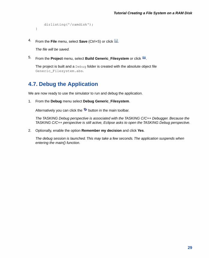
dirlisting("/ramdisk");
printf( "Create directory\n" ); rc = mkdir( "/ramdisk/dir1", S_IRWXU | S_IRWXG | S_IRWXO ); if (rc) { printf("Error: mkdir returned %d\n", rc); }
FILE *f = fopen("/ramdisk/test.txt", "w"); if (f == NULL) { printf("Error: fopen returned NULL\n"); } fwrite("TEST", 4, 1, f); fclose(f);
28
Introduction to the TASKING Software Platform for ARM
dirlisting("/ramdisk");}
4. From the File menu, select Save (Ctrl+S) or click .
The file will be saved.
5. From the Project menu, select Build Generic_Filesystem or click .
The project is built and a Debug folder is created with the absolute object fileGeneric_Filesystem.abs.
4.7. Debug the Application
We are now ready to use the simulator to run and debug the application.
1. From the Debug menu select Debug Generic_Filesystem.
Alternatively you can click the button in the main toolbar.
The TASKING Debug perspective is associated with the TASKING C/C++ Debugger. Because theTASKING C/C++ perspective is still active, Eclipse asks to open the TASKING Debug perspective.
2. Optionally, enable the option Remember my decision and click Yes.
The debug session is launched. This may take a few seconds. The application suspends whenentering the main() function.
29
Tutorial Creating a File System on a RAM Disk

3. To resume execution, from the Debug menu, select Resume, or press F8, or click on the Resume
button ( ).
The application is executed. The FSS view now shows:
Mount filesystemContents of folder "/ramdisk":
Create directoryContents of folder "/ramdisk":[DIR] DIR1/[FILE] TEST.TXT (4 bytes)
Congratulations, you just made an example Software Platform application.
For more information about debugging an application see Chapter Debugging your Application of theGetting Started with the TASKING VX-toolset, and Chapter Using the Debugger of the TASKING VX-toolsetfor ARM User Guide.
30
Introduction to the TASKING Software Platform for ARM

Chapter 5.Tutorial Using a Library WrapperIn this tutorial we show how to use the Software Platform as a wrapper to access library functions fromSTMicroelectronics.You will learn how to use a UART for communication over a serial port. This exampleuses the STM3210E-EVAL evaluation board.
5.1. Create a Project
As explained in the previous chapter, the first step is to create a C project.
1. From the File menu, select New » TASKING ARM C/C++ Project
The New C/C++ Project wizard appears.
2. Enter a name for your project, for example USART_printf.
In the Location field you will see the location where the new project will be stored.
3. In the Project type box you can select whether to create an application or a library.
• Expand TASKING ARM Application and select Empty Project. This creates a project without aC source file.
• Click Next to continue.
The ARM Project Settings page appears.
4. Select the target processor core or architecture for which you want to build the application. In thisexample, we select STM32F103ZG. Afterwards you can always change the processor in the Project» Properties for dialog.
31

5. Leave the rest of the dialog as is and click Next.
The Target Settings page appears.
6. In order to debug your project you need to create a debug configuration.
• Select a target. For this tutorial select STMicroelectronics STM3210E-Eval board.
• For connection select J-Link over USB or ST-LINK over USB.
• Enable Add launch configuration to the project. This allows you to debug your project.
• Leave the other tabs as is. For more information, see section Creating a Customized DebugConfiguration in Chapter Using the Debugger of the TASKING VX-toolset for ARM User Guide.
7. Click Finish to finish the wizard and to create the project.
The project has now been created and is the active project.
5.2. Add a Software Platform Document
Now that we have a project we can add a Software Platform document.
1. From the File menu, select New » TASKING Software Platform Document.
The New Software Platform Document dialog appears.
2. Leave the project name and file name as is and click Finish.
A new Software Platform document is added to the active project (USART_printf.swpxmi).
TASKING Software Platform Builder editor
Double-click on the Software Platform document USART_printf.swpxmi to open it.The editor consistsof two sections: the Software Services and the Device Stacks.
32
Introduction to the TASKING Software Platform for ARM

5.3. Add the Services and Device Stacks
Now it is time to add a USART peripheral and connect a library wrapper to it.
Add a software service or device stack
1. From the Software Platform menu, select Add... or click .
The Add Software Services and Device Stacks dialog appears.The left side shows the stack services,software services and drivers. The right side shows all peripherals for the selected device.
2. From the Repository, select TASKING Device Support for STM32
Only services and drivers and peripherals from the selected repository are shown.
3. From the Peripherals, select STM32F10X_USART1 and click OK.
The new device stack and software service appear in the TASKING Software Platform editor. TheSTM32 CMSIS Core, STM32 Pin Mapper and STM32F10X Peripheral Access Library softwareservices appear automatically because it is required by the peripheral.
33
Tutorial Using a Library Wrapper

4. Right-click on the STM32F10X USART stack item and select Grow Stack Up from the pop-up menu.
The Grow Stack dialog appears. The dialog shows all possible combinations of sub-stacks that youcan place on top of the selected module.
34
Introduction to the TASKING Software Platform for ARM
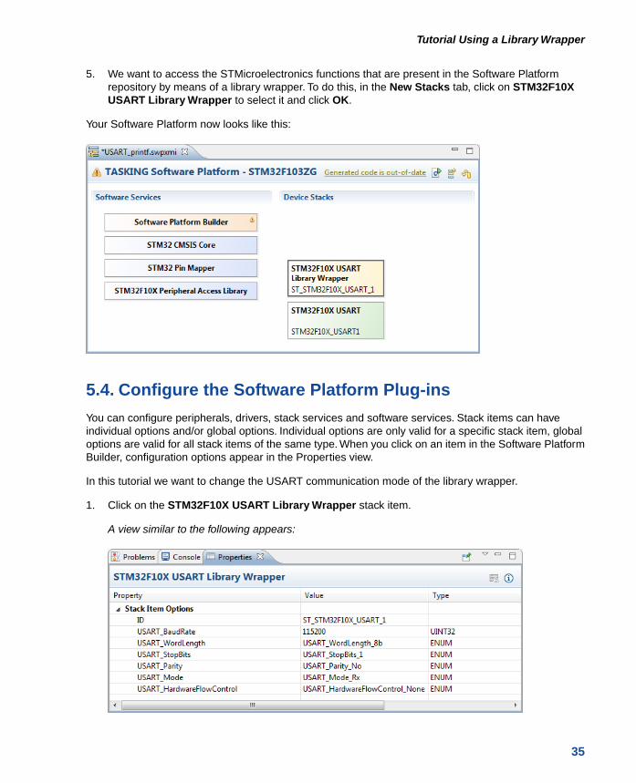
5. We want to access the STMicroelectronics functions that are present in the Software Platformrepository by means of a library wrapper. To do this, in the New Stacks tab, click on STM32F10XUSART Library Wrapper to select it and click OK.
Your Software Platform now looks like this:
5.4. Configure the Software Platform Plug-ins
You can configure peripherals, drivers, stack services and software services. Stack items can haveindividual options and/or global options. Individual options are only valid for a specific stack item, globaloptions are valid for all stack items of the same type. When you click on an item in the Software PlatformBuilder, configuration options appear in the Properties view.
In this tutorial we want to change the USART communication mode of the library wrapper.
1. Click on the STM32F10X USART Library Wrapper stack item.
A view similar to the following appears:
35
Tutorial Using a Library Wrapper

2. Change the value of USART_Mode to USART_Mode_Rx + USART_Mode_Tx.
The properties for STM32F10X USART Library Wrapper should now look like this:
5.5. Generate the Source Code
Now that you have added and configured the Software Platform plug-ins you are ready to generate theSoftware Platform sources for your project.
1. From the Software Platform menu, select Generate Code or click .
The Software Platform sources are retrieved from the repositories and are added to your project inthe folder SoftwarePlatform. Tool options such as defines and include paths are added to theGenerated options field in your project properties. Options can also be set on the SoftwarePlatformfolder and/or sub-folders.
2. From the File menu, select Save (Ctrl+S) or click .
The Software Platform document will be saved.
36
Introduction to the TASKING Software Platform for ARM

5.6. Configure the Pins
Now that the Software Platform software services and device stacks are defined, you need to configurethe pins of the peripheral. In this case the USART.You can do this with the TASKING Pin Mapper.
1. From the File menu, select New » TASKING Pin Mapper Document.
The New TASKING Pin Mapper Document wizard appears.
2. Select the Project folder for the Pin Mapper document: type the name of your project (USART_printf)or click the Browse button to select a project.
3. In the File name field, enter a name for the Pin Mapper document, for exampleUSART_printf.pincfg and click Next.
The Device and Package page appears.
4. Select the processor and package that is used on the board and click Finish. In our example, weuse the STM3210E-Eval board, which has a STM32F103Z(F-G)Tx and package LQFP144.
A pin configuration file with extension .pincfg is added to the existing project. Because the TASKINGC/C++ perspective is still active, Eclipse asks to open the TASKING Pin Mapper perspective.
5. Optionally, enable the option Remember my decision and click Yes.
The TASKING Pin Mapper perspective is opened.
6. In the Pin Selection pane, select Peripherals » USART1.
37
Tutorial Using a Library Wrapper

7. In the Pin Configuration pane, set the Mode to UART, No Handshake, No Remap.
This selection automatically connects RX to PA10 and TX to PA9. A green check mark appears ifthe connection is successful.
8. From the File menu, select Save (Ctrl+S) or click to save the configuration.
9. From the Pin Mapper menu, select Generate Code or click .
The Pin Mapper sources are generated and are added to your project in the folder PinMapper.
10. Return to the TASKING C/C++ perspective.
5.7. Write and Build the Application
Now that the Software Platform sources have been generated we can use it to write an application. Inthis tutorial we use the USART port on the evaluation board to send a message to the PC.This applicationuses the library wrapper function stm32_usart_open to configure the USART as specified by the stackitem options, which makes it easier to access the USART.
1. From the File menu, select New » Source File.
The New Source File dialog appears.
2. Enter the source file name main.c and click Finish.
The new file main.c is created and ready for editing in the editor view.
3. Add the following C source to the file main.c.
38
Introduction to the TASKING Software Platform for ARM
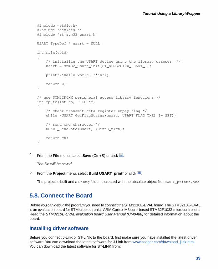
#include <stdio.h>#include "devices.h"#include "st_stm32_usart.h"
USART_TypeDef * usart = NULL;
int main(void){ /* initialize the USART device using the library wrapper */ usart = stm32_usart_init(ST_STM32F10X_USART_1);
printf("Hello world !!!\n");
return 0;}
/* use STM32F0XX peripheral access library functions */int fputc(int ch, FILE *f){ /* check transmit data register empty flag */ while (USART_GetFlagStatus(usart, USART_FLAG_TXE) != SET);
/* send one character */ USART_SendData(usart, (uint8_t)ch);
return ch;}
4. From the File menu, select Save (Ctrl+S) or click .
The file will be saved.
5. From the Project menu, select Build USART_printf or click .
The project is built and a Debug folder is created with the absolute object file USART_printf.abs.
5.8. Connect the Board
Before you can debug the program you need to connect the STM3210E-EVAL board.The STM3210E-EVALis an evaluation board for STMicroelectronics ARM Cortex-M3 core-based STM32F103Z microcontrollers.Read the STM3210E-EVAL evaluation board User Manual (UM0488) for detailed information about theboard.
Installing driver software
Before you connect J-Link or ST-LINK to the board, first make sure you have installed the latest driversoftware.You can download the latest software for J-Link from www.segger.com/download_jlink.html.You can download the latest software for ST-LINK from:
39
Tutorial Using a Library Wrapper

http://www.st.com/web/en/catalog/tools/PF258167 (Windows 7, XP),
http://www.st.com/web/en/catalog/tools/PF259459 (Windows 8).
Jumper settings
Set jumper JP13 to PSU for power through the 5V DC power jack.
Connecting the board
1. Connect any of the J-Link or ST-LINK debugger probes with the 20-pin JTAG/SWD cable to theboard.
2. Connect J-Link or ST-LINK to a PC with a USB cable.
3. Connect port USART1 with a serial cable to a PC.
4. Power the board with the 5V DC power adapter connected to the power jack on the board (CN17).
5.9. Debug the Application
We are now ready to use the evaluation board to run and debug the application.
To see the output of the application on your PC you can use a terminal emulator.
1. From the Debug menu select Debug USART_printf.
Alternatively you can click the button in the main toolbar.
The TASKING Debug perspective is associated with the TASKING C/C++ Debugger. Because theTASKING C/C++ perspective is still active, Eclipse asks to open the TASKING Debug perspective.
2. Optionally, enable the option Remember my decision and click Yes.
The debug session is launched. This may take a few seconds. The application suspends whenentering the main() function.
40
Introduction to the TASKING Software Platform for ARM
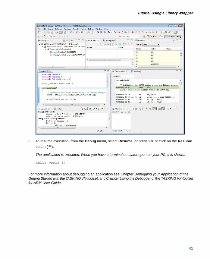
3. To resume execution, from the Debug menu, select Resume, or press F8, or click on the Resume
button ( ).
The application is executed. When you have a terminal emulator open on your PC, this shows:
Hello world !!!
For more information about debugging an application see Chapter Debugging your Application of theGetting Started with the TASKING VX-toolset, and Chapter Using the Debugger of the TASKING VX-toolsetfor ARM User Guide.
41
Tutorial Using a Library Wrapper

42
Introduction to the TASKING Software Platform for ARM
Chapter 6.Tutorial Creating a LocalRepositoryIn this tutorial we show how to create your own Software Platform repository. This can be useful whenyou want to create your own plug-ins or to adapt existing plug-ins to suit your needs.
We assume that the Generic_Filesystem project of Chapter 4, Tutorial Creating a File System on aRAM Disk is still present in the C/C++ Projects view.
6.1. Create a Local Repository Project
To use a local repository we need to create a project. This does not have to be a toolset project, becausewe do not have to compile anything. It is just a container for your local plug-ins. Therefore, it can be ageneral project.
1. From the File menu, select New » Project
The New Project wizard appears.
2. Select General » Project and click Next.
The Project page appears.
3. Enter a name for your project, for example My_Repository.
In the Location field you will see the location where the new project will be stored.
4. Click Finish to finish the wizard and to create the project.
The project has now been created and is visible in the C/C++ Projects view.
6.2. Add a Software Platform Plug-in
You can copy existing plug-ins as a starting point, or you can write one from scratch. In this tutorial wemake a copy of a plug-in that was generated in the tutorial of Chapter 4, Tutorial Creating a File Systemon a RAM Disk.
1. From the Generic_Filesystem project, right-click on the ramdisk folder inSoftwarePlatform/platform/generic/drivers and select Copy.
The exact path depends on the directory structure of the Software Platform repository fromwhich the plug-in is retrieved.You can find out the correct path when you click the Show
Resource Info button ( ) in the Properties view of the RAM Disk.
43

2. Right-click on the My_Repository project and select New » Folder.
The New Folder dialog appears.
3. Select the My_Repository parent folder if it has not been selected already.
4. In the Folder name field enter a name to categorize the type of plug-ins. For this tutorial, enterMy_customized_plugins and click Finish.
5. Right-click on the My_customized_plugins folder and select Paste.
A copy of the ramdisk plug-in is now present in the local repository.
6.3. Modify the Software Platform Plug-in
As long as the name of a plug-in does not change, the new plug-in overrules the plug-in in the defaultrepository. In this tutorial we will only alter the caption (the name of the stack item) of the RAM disk plug-inwe just copied.
1. Open the My_Repository project and open the ramdisk.Plugin file.
44
Introduction to the TASKING Software Platform for ARM

The file ramdisk.Plugin appears in the editor view.
2. Under the [Plugin] part, change the line
Caption=RAM Disk
into
Caption=My RAM Disk
If a question appears that the file is read-only and if you wish to make it writable, click Yes.
3. From the File menu, select Save (Ctrl+S) or click .
The file will be saved.
6.4. Use the Local Repository
Now that we have a local repository, we want to use it in the Generic_Filesystem project that wecreated in Chapter 4, Tutorial Creating a File System on a RAM Disk.
You can use Eclipse platform URLs or a file URL to specify the location of a repository or you can use abrowse button. The following URLs are supported.
DescriptionURL
This URL is used to identify a resource located in the workspace.The next pathsegment after "resource" should be the name of a project, which can be followedby the folder and/or file we want to locate.
platform:/resource
This URL is used to locate a resource available in a Eclipse plug-in/bundle.The path segment after "plugin" should be the identifier of the bundle, whichcan be followed by the path of the resource in the bundle. This URL is usedinternally for the default Software Platform repository.
platform:/plugin
This URL is used to specify a local file or directory.file://
45
Tutorial Creating a Local Repository
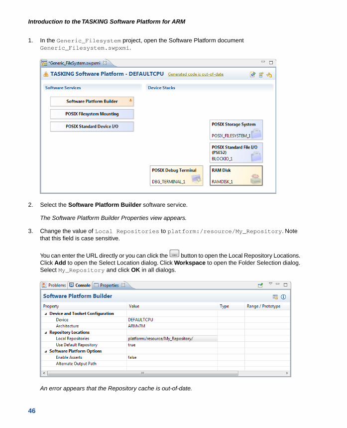
1. In the Generic_Filesystem project, open the Software Platform documentGeneric_Filesystem.swpxmi.
2. Select the Software Platform Builder software service.
The Software Platform Builder Properties view appears.
3. Change the value of Local Repositories to platform:/resource/My_Repository. Notethat this field is case sensitive.
You can enter the URL directly or you can click the button to open the Local Repository Locations.Click Add to open the Select Location dialog. Click Workspace to open the Folder Selection dialog.Select My_Repository and click OK in all dialogs.
An error appears that the Repository cache is out-of-date.
46
Introduction to the TASKING Software Platform for ARM

4. From the Software Platform menu, select Reload Repository or click .
As you can see, the RAM Disk stack item has been replaced by My RAM Disk.
If you would generate code again ( ), the existing plug-in in the generated SoftwarePlatform folderis replaced by the plug-in from My_Repository. As you can see the My_customized_plugins folderhas been added to the Generic_FileSystem project.
47
Tutorial Creating a Local Repository
48
Introduction to the TASKING Software Platform for ARM

Chapter 7. Content of the Default ARMRepositoriesThe chapter describes the content of the default ARM repositories.
When Altium releases a new version of a repository you can update this repository by using the AvailableUpdates wizard.
To check for updates
1. From the Help menu, select Check for Updates.
The Available Updates wizard appears.
2. Follow the steps in the wizard and click Finish.
Online repository documentation
Each repository contains detailed descriptions of its contents.You can access this documentation fromthe Help menu (Help » Help Contents » Software Platform Repository Reference - ...).
7.1.TASKING POSIX Repository
The Portable Operating System Interface POSIX® is a set of well-established standards that define astandardized way for an application to interface to the operating system. Because of the aim of portabilityand readability we have chosen POSIX as our standard interfaces at application level for at least thekernel (multithreading), device I/O and networking services.
The POSIX standards do not specify how services must be implemented, just their semantics. Implementerscan choose their implementation as long as they follow the specification of the interface.These standardshave become the de-facto programming standards also for embedded environments.
The complete set of POSIX services as defined in the standard may be useful for large applications, butthe set is considered to be too large for most embedded systems. Embedded systems usually have tightmemory requirements, may not have memory management capabilities, and may not even have asecondary memory for implementing the UNIX file system.
For these reasons the POSIX standard recognizes the need for the creation of subsets of the operatingsystem services. The IEEE Std 1003.13-2003 edition (POSIX.13) describes four real-time applicationenvironment profiles and their minimum hardware requirements.
The TASKING POSIX implementation conforms to the PSE51 profile for Minimal Real-time Systems andsupports:
• Multi-threading
• Standard device I/O
49
• Standard file I/O (PSE52)
• Standard device Shared Memory routines
• File system interface for accessing sockets (PSE53)
• File system interface for accessing shared memory objects
• Basic support for message passing (PSE52)
• Basic support for signals
• FAT File System
Some features have limited functionality for devices without peripheral support.
For more information see the TASKING POSIX Implementation.
7.2. STM32 Repository
The STM32 repository contains all STM32 specific content, like peripherals, low-level drivers and librarywrappers. Support is included for the following device families:
• STMicroelectronics STM32F0xx
• STMicroelectronics STM32F10x
• STMicroelectronics STM32F2xx
• STMicroelectronics STM32F30x
• STMicroelectronics STM32F37x
• STMicroelectronics STM32F4xx (no FP support)
• STMicroelectronics STM32L1xx
This repository contains software/firmware from STMicroelectronics which is licensed under MCD-STLiberty SW License Agreement V2.You may not use this package except in compliance with this License.You may obtain a copy of the License at:
http://www.st.com/software_license_agreement_liberty_v2 (PDF)
50
Introduction to the TASKING Software Platform for ARM

7.3. EFM32 Repository
The EFM32 repository contains all Silicon Labs EFM32 specific content, like peripherals, low-level driversand library wrappers. Support is included for the following device families:
• EFM32 Gecko
• EFM32 Giant Gecko
• EFM32 Leopard Gecko
• EFM32 Tiny Gecko
• EFM32 Wonder Gecko
• EFM32 Zero Gecko
This repository contains software/firmware from Silicon Laboratories which is licensed. See the top ofeach file for detailed information. Basically you are free to use the Silicon Labs code for any project usingSilicon Labs devices.
7.4. Generic Repository
Software services, drivers and peripherals in the generic repository are provided as Bonus Technologyas described in the Altium EULA. Some third-party software is included which may require special licenseagreements. Check the generated code for the exact license usage conditions.
Software services
The following table contains an overview of the software services present in the generic repository.
DescriptionSoftware Service
Generic interface to Advanced Encryption Standard (AES)encryption modules.
AES
Interface to audio controller services.Audio Service
Bluetooth Human Interface Device (HID) class. Interfacesto bluetooth service.
Bluetooth HID Service
Bluetooth interface.Bluetooth Service
Service for ethernet peripherals.Ethernet Protocol Services
GPS-NMEA decoder.GPS-NMEA Services
Service for graphics routines, low-level drawing functionality.Graphics Services
The Altium Graphical User Interface (AGUI) containscomponents you can use to build a User Interface.
GUI Services
HTTP interface.HyperText Transfer Protocol
Interrupt services. Used by interrupt-driven driver software.Interrupt Management
51
Content of the Default ARM Repositories

DescriptionSoftware Service
Basic implementation to decode a JPEG image.JPEG Decoder
Basic implementation to encode a JPEG image.JPEG Encoder
Interface to YAJL's JSON generation facilities.JSON Parser
Generic interface to GPS-NMEA or Simcom AT GPSservices.
Location Services
SSL and TLS implementation designed for small footprintapplications and devices.
Matrix SSL / TLS
Services to communicate with modems using Hayes ATcommands.
Modem Services
LWIP PPP service.Point-to-Point Protocol Services
The pointer service keeps the current pointer positionup-to-date depending on the input from mouse and/ortouchscreen.
Pointer Services
GPS receiver.Simcom AT GPS Service
Timing and timer services.Software Timing Services
AutoIP Automatic LinkLocal IP Configuration.TCP/IP Networking
Interface to touchscreen controller services.Touchscreen Services
Driver for USB Host Bluetooth HCI.USB Host Bluetooth HCI Service
Driver for USB Host Hub.USB Host Hub Service
Driver for USB Host Keyboard.USB Host Keyboard Service
Driver for USB Host MSD.USB Host Mass Storage Service
Driver for USB Host Mouse.USB Host Mouse Service
Generic USB Host service.USB Host Service
Driver for USB Host UVC.USB Host Video Service
This module partially implements RFC4122.UUID Generator
Generic drivers
Generic drivers provide a generic interface to a certain type of peripheral. If the application uses thegeneric interface, then the hardware specific driver can be changed without the need to modify theapplication. For example, you can have a generic ADC driver that interfaces with an ADC084S021 ADCdriver (SPI).
DescriptionDriver
Generic low-rate wireless PAN driver.802.15.4 LR-WPAN
Software implementation of the Advanced EncryptionStandard (AES).
AES Encryption/Decryption
Platform independent generic external interrupt support.External Interrupt
Generic interface for Analog-to-Digital Converters.Generic ADC Driver
52
Introduction to the TASKING Software Platform for ARM

DescriptionDriver
Generic interface for Controller Area Networks.Generic CAN Driver
Generic interface for Digital-to-Analog Converters.Generic DAC Driver
Generic interface for Pulse-Width Modulation.Generic PWM Driver
Generic interface for Real Time Clocks.Generic RTC Driver
Interface for the creation of memory based file systems.RAM Disk
External drivers
External drivers are drivers for off-chip peripherals. These off-chip peripherals are connected to the chipas an SPI slave device, an I2C slave device, or via some other interface such as GPIO or DMA. In theformer two cases an on-chip SPI master peripheral or an on-chip I2C master peripheral is required. Forexample, the ADC084S021 ADC driver (SPI slave) requires the STM32 SPI driver.
The following tables contain an overview of the external drivers present in the generic repository. Somedrivers appear in more than one table, which means that they can have more than one interface.
External drivers - I2C
DescriptionDriver
External driver to turn power on or off of a light photo sensor.APDS9300 Light Photo Sensor Driver
External driver to interface with the BMP085 Digital PressureSensor.
BMP085 Pressure Sensor Driver
Interface to I2C control port of CS4322 stereo audio CODEC.CS4322 Audio Codec Driver
Interface to LIS302DL MEMS motion sensor.LIS302DL MEMS Motion Sensor
Interface to STLM75 Digital Temperature Sensor & ThermalWatchdog.
LM75 Temperature Sensor
Interface to I2C based M24Cxx serial flash memory devicedriver
M24Cxx Serial I2C Bus EEPROM Driver
Interface to the MAX1037 AD converter device driver.MAX1037 ADC Driver
Interface to the MAX5841 DA converter device driver.MAX5841 DAC Driver
Device driver for MAX6966 (10-Port Constant-Current LEDDriver) peripheral.
MAX6966 LED Driver
Device driver for MCP3021 A/D Converter.MCP3021 A/D Converter
Driver for SSD0300 OLED display over I2C.SSD0300 I2C OLED Driver
Interface to STMPE811 touchscreen controller / GPIOexpander.
STMPE811 Touchscreen Controller / GPIOExpander
Driver to access configuration registers of a TVP5150 videoinput decoder device over an I2C bus.
TVP5150 Video Decoder Driver
53
Content of the Default ARM Repositories
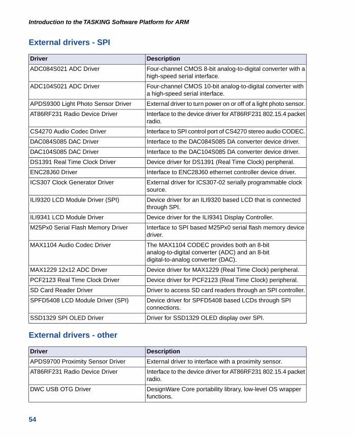
External drivers - SPI
DescriptionDriver
Four-channel CMOS 8-bit analog-to-digital converter with ahigh-speed serial interface.
ADC084S021 ADC Driver
Four-channel CMOS 10-bit analog-to-digital converter witha high-speed serial interface.
ADC104S021 ADC Driver
External driver to turn power on or off of a light photo sensor.APDS9300 Light Photo Sensor Driver
Interface to the device driver for AT86RF231 802.15.4 packetradio.
AT86RF231 Radio Device Driver
Interface to SPI control port of CS4270 stereo audio CODEC.CS4270 Audio Codec Driver
Interface to the DAC084S085 DA converter device driver.DAC084S085 DAC Driver
Interface to the DAC104S085 DA converter device driver.DAC104S085 DAC Driver
Device driver for DS1391 (Real Time Clock) peripheral.DS1391 Real Time Clock Driver
Interface to ENC28J60 ethernet controller device driver.ENC28J60 Driver
External driver for ICS307-02 serially programmable clocksource.
ICS307 Clock Generator Driver
Device driver for an ILI9320 based LCD that is connectedthrough SPI.
ILI9320 LCD Module Driver (SPI)
Device driver for the ILI9341 Display Controller.ILI9341 LCD Module Driver
Interface to SPI based M25Px0 serial flash memory devicedriver.
M25Px0 Serial Flash Memory Driver
The MAX1104 CODEC provides both an 8-bitanalog-to-digital converter (ADC) and an 8-bitdigital-to-analog converter (DAC).
MAX1104 Audio Codec Driver
Device driver for MAX1229 (Real Time Clock) peripheral.MAX1229 12x12 ADC Driver
Device driver for PCF2123 (Real Time Clock) peripheral.PCF2123 Real Time Clock Driver
Driver to access SD card readers through an SPI controller.SD Card Reader Driver
Device driver for SPFD5408 based LCDs through SPIconnections.
SPFD5408 LCD Module Driver (SPI)
Driver for SSD1329 OLED display over SPI.SSD1329 SPI OLED Driver
External drivers - other
DescriptionDriver
External driver to interface with a proximity sensor.APDS9700 Proximity Sensor Driver
Interface to the device driver for AT86RF231 802.15.4 packetradio.
AT86RF231 Radio Device Driver
DesignWare Core portability library, low-level OS wrapperfunctions.
DWC USB OTG Driver
54
Introduction to the TASKING Software Platform for ARM

DescriptionDriver
External driver to interface with a humidity sensor.HIH5030 Humidity Sensor Driver
Device driver for an ILI9320 based LCD that is connectedto the parallel interface.
ILI9320 LCD Module Driver (parallel)
Device driver for the ILI9341 Display Controller.ILI9341 LCD Module Driver
Interface to M25Px0 parallel flash memory device driver.M25Px0 Flash Memory Block I/O
Device driver for SPFD5408 based LCDs through parallelconnections.
SPFD5408 LCD Module Driver (parallel)
Driver for SSD1329 OLED display over SPI.SSD1329 SPI OLED Driver
Driver for ST7637 LCD display with parallel interface.ST7637_PAR LCD Driver
55
Content of the Default ARM Repositories

56
Introduction to the TASKING Software Platform for ARM

Chapter 8. GlossaryThe following terminology is used to describe the TASKING Software Platform concepts (in alphabeticalorder).
Software Platform
The source code generated by the Software Platform Builder. The source code becomes part of yourproject. A graphical representation of the Software Platform is present in the Software Platform Builder.
Software Platform Builder
The graphical editor where you can edit a Software Platform document and where you can generate thesource code for your Software Platform. The editor shows a graphical representation of your SoftwarePlatform.
Software Platform document
A file with extension .swpxmi which is part of your project. It contains the configuration of your SoftwarePlatform and is managed by the Software Platform Builder.
Software Platform plug-in or module
Software Platform definition files, source code and other resources. Plug-ins are bundled in a SoftwarePlatform repository.
Software Platform repository
The collection of Software Platform plug-ins. It provides the contents for a generated Software Platform.
TASKING Software Platform
The main software framework delivered by Altium, consisting of Software Platform repositories and theSoftware Platform Builder.
57

58
Introduction to the TASKING Software Platform for ARM