Embed Size (px)
Citation preview
Printed on 12/07/12
Introduction to Trickling Filters and RBC's Study Guide
Subclass B
Wisconsin Department of Natural ResourcesBureau of Science Services
Operator Certification ProgramP.O. Box 7921, Madison, WI 53707
http://dnr.wi.gov
September 1995 Edition
Wisconsin Department of Natural Resources
The Wisconsin Department of Natural Resources provides equal opportunity in its employment, programs, services, and functions under an Affirmative Action Plan. If you have any questions, please write to Equal Opportunity Office, Department of Interior, Washington, D.C. 20240. This publication is available in alternative format (large print, Braille, audio tape. etc.) upon request. Please call (608) 266-0531 for more information.
Wastewater Operator Certification
Printed on 12/07/12
PrefaceThis operator's study guide represents the results of an ambitious program. Operators of wastewater facilities, regulators, educators and local officials, jointly prepared the objectives and exam questions for this subclass.
How to use this study guide with references
In preparation for the exams you should:
1. Read all of the key knowledges for each objective.
2. Use the resources listed at the end of the study guide for additional information.
3. Review all key knowledges until you fully understand them and know them by memory.
It is advisable that the operator take classroom or online training in this process before attemptingthe certification exam.
Choosing A Test Date
Before you choose a test date, consider the training opportunities available in your area. A listing of training opportunities and exam dates is available on the internet at http://dnr.wi.gov, keyword search "operator certification". It can also be found in the annual DNR "Certified Operator" or by contacting your DNR regional operator certification coordinator.
AcknowledgementsSpecial appreciation is extended to the many individuals who contributed to this effort.
Thomas A. Kroehn, Director of Office of Operations and Maintenance, DNR.
Thomas P. Mickelson, Coordinator, Operator Certification and Training, DNR.
Wastewater operators were represented by:
Mike Bechel - ElmwoodCraig Cappen - Eau ClaireJerry Carroll - Eau ClaireRon Clish - Eau ClaireBert Enstad - Sun PrairieKevin Freber - WatertownMike Gabrick - Fountian CityPaul Lange - WatertownWilliam Long - Lodi
Introduction to Trickling Filters and RBC's Study Guide - September 1995 Edition
Printed on 12/07/12
Walter Luttenberger - WaupunTom Mortinger - WaukeshaKim Putz - ST. Croix FallsGary Risen - MondoviWilbur Salzwell - EttrickGary Sweeney - DurandArt Thompson - New GlarusBob Todahl - Eleva
VTAE and educational interests were represented by:
Glenn Smeaton - VTAE District ConsortiumPat Gomez - Moraine Park Technical College
DNR District Offices were represented by:
Larry Schaefer, Western District, Eau ClaireJohn Kling, Western District, Eau Claire
DNR Central Office was represented by:
John Melby, MadisonRon Wilhelm, Madison
Printed on 12/07/12
Chapter 1 - Principle, Structure and Function
Chapter 2 - Operation and Maintenance
Chapter 3 - Monitoring and Troubleshooting
Chapter 4 - Safety and Calculations
Section 1.1 - Principles of Trickling Filters and RBC'sSection 1.2 - Structure and Function
Section 2.1 - OperationSection 2.2 - Maintenance
Section 3.1 - MonitoringSection 3.2 - Troubleshooting
Section 4.1 - SafetySection 4.2 - Calculations
Table of Contents
Introduction to Trickling Filters and RBC's Study Guide - September 1995 Edition
pg. 1pg. 2
pg. 4pg. 8
pg. 11pg. 11
pg. 13pg. 14
Printed on 12/07/12Page 1 of 19
Chapter 1 - Principle, Structure and Function
Section 1.1 - Principles of Trickling Filters and RBC's
The main function of trickling filters and RBC's is to provide secondary treatment of primary settled wastewater. They function to remove dissolved organics and finely divided organic solids using microorganisms attached to the media. The growth on the media oxidizes organic materials biologically to form a more stable material.
They remove dissolved and non-settleable solids as a result of the growth of bacteria and other microorganisms on the media. The biological growth of these organisms uses the dissolved organic material in the presence of oxygen as a food source. This produces cell mass. Finely divided organic solids are also adsorbed on the cell walls of the microorganisms.
As cell mass grows a portion is sloughed-off and this material is then removed by settling in a final clarifier. As with all biologic type secondary treatment systems, wastewater soluble BOD, and suspended solids (SS) are converted to a settleable biologic sludge.
The growth formed on the media is a mixture of mainly aerobic microorganisms. These organisms are similar to those found in other secondary biological treatment processes.Included would be bacteria, free swimming and stalked ciliates, rotifers, nematodes, and many others.
Trickling filters and RBC's are used to treat domestic wastewater and industrial organic loadings from processes, such as milk processing wastes and canneries. Trickling filters and RBC's can be used for most applications treating organic-type wastes and can handle shock loadings well.
The main purpose of the media is to provide a surface on which microorganism's can grow. It is designed to allow for easy contact of both air and wastewater. This ensures good treatment and the sloughing of solids from the media without plugging.
In a trickling filter the media must be durable so it does not disintegrate in normal operations. It is necessary to maintain void spaces for microorganisms and oxygen movement through the filter. If the media does fail it can cause plugging of the filter and under-drains. This can cause ponding.
Algae is a green plant and it only grows on the surface where light is present allowing photosynthesis to occur.
Buildings or covers are constructed to keep out light to prevent this growth so algae growth
1.1.1
1.1.2
1.1.3
1.1.4
Describe the wastewater treatment process of trickling filters and rotating biological contactors (RBC's).
Discuss the types of waste treated by a trickling filter and a RBC.
Explain the purpose served by the media in a trickling filter and on a RBC.
Describe the effect of algae growth on the media of a trickling filter and a RBC.
Introduction to Trickling Filters and RBC's Study Guide - September 1995 Edition
Printed on 12/07/12Page 2 of 19
Section 1.2 - Structure and Function
is seldom a serious problem. On uncovered trickling filters algae growth is only a serious problem if it becomes thick enough to cause ponding.
1. Prevent heavy large solid materials from plugging the media and openings in the discs severely affecting treatment efficiency
2. Remove grease which would coat the media preventing or significantly reducing the growth of microorganisms
3. Primary treatment reduces organic loading to the secondary treatment units
The retaining structure for trickling filters is usually a circular wall constructed of reinforced concrete, concrete block, or vitrified clay blocks. These walls may be constructed with openings or may be solid. With solid walls the filter can be flooded to correct some operational problems while walls with openings provide better ventilation of the filter media.
Various materials have been used for filter media. Hard stone (dolomite, hard limestone, and quartzite, etc.), various ceramics, redwood blocks or slats, and more recently synthetic (plastic) media of various kinds have been used. Historically stone media has been most commonly used. The new types of synthetic plastic media provide some advantages over stone. These advantages include greater surface area per cubic foot and a higher percentage of void spaces. This allows for greater hydraulic and organic loads. Common rock media is less expensive than plastic.
The most commonly used material today is a plastic corrugated sheet which is fabricated from high-density polyethylene.
The organisms that feed on sugar and starch (carbonaceous BOD) act quickly and have a tendency to build-up on the first stages of a RBC unit. Disc configurations that have larger openings for aeration and have less surface for solids accumulation are used in the early RBC stages to handle the higher levels of carbonaceous BOD.
The organisms feeding on the later stages of a RBC unit have less food, especially less carbonaceous BOD, and have a tendency to produce less buildup of biomass. Disc configurations with one and one half to two times the area are used in this application to provide as much food to bacteria contact as possible.
1.1.5
1.2.1
1.2.2
List the reasons why good primary treatment is needed for effective trickling filter and RBC operation.
Describe the containment and types of media used in trickling filters.
Describe the type of media and stages used on a RBC.
Introduction to Trickling Filters and RBC's Study Guide - September 1995 Edition
Printed on 12/07/12Page 3 of 19
A. Underdrains: rest on the floor of the filter and support the media; the underdrains collect the filter effluent and convey it to the final clarifier; the underdrains act as a ventilation systemto convey air to the filter; it is common to design underdrains to flow only one-third to one-half full at design flow; underdrains usually are made of vitrified clay or concrete
B. Reactionary distributors: most of the trickling filters in operation today use reaction driven rotary distributors; they would be described as two or more horizontal pipes supported by a central column; wastewater is spread over the filter by orifices or nozzles located on one side of the horizontal pipe arms; the arms rotate about the center feed column due to the reaction (jet action) of the wastewater discharging from the nozzles; the movement of the arms is dependent on wastewater flow; during low flow periods it is necessary to recirculate flows to maintain continuous operation; very few trickling filters use electric motors to mechanically drive the distributor arms
C. Distributor end gates: serve several purposes; they act as a clean-out for removing any material or debris that may be in the arms; by opening the end gates the reaction force of the flowing wastewater will be stopped and the arms will stop; end gates are used to reducethe speed of the arms by partially being opened to reduce the reactionforce of the flowing wastewater; operating with the end gates partially open is not a good practice as this does not distribute the flow uniformily over the filter reducing treatment efficiency; if the end gates have to be partially opened to reduce rotational speed of the arms a permanent and better solution for this problem would be to install speed retarder nozzles (see D)
D. Speed retarder nozzles (orifices): are located on the opposite side of the trickling filter arm from the driving orifices; these retarder nozzles provide reaction forces opposite to the driving nozzles and slow-down the rotational speed of the filter arms
E. Turnbuckles and stay rods (guy wires): connected to the central column on trickling filter arms are used to structurally support the arms; the turnbuckles on the guy rods are used to adjust and level the arms; this adjustment may need to be done seasonally to correct for temperature changes
F. Inlet and outlet valves: the outlet valve on a trickling filter is located at the discharge pointof the filter usually in an outlet box; the main purpose of this valve would be to allow the operator to close the valve and flood the filter to correct operational problems; this valve along with the inlet valve can be used to isolate the filter
1.2.3 Discuss the structure and function of the following trickling filter mechanisms:
A. UnderdrainsB. Reactionary distributorsC. Distributor end gatesD. Speed retarder nozzles (orifices)E. Turnbuckles and stay rods (guy wires)F. Inlet and outlet valves.
Introduction to Trickling Filters and RBC's Study Guide - September 1995 Edition
Printed on 12/07/12Page 4 of 19
Chapter 2 - Operation and Maintenance
Section 2.1 - Operation
A. Mechanical drive: units are powered by an electric motor driving a reduction gear box togive the desired rotational speed
B. Air drive: units use diffused air that is released from headers under the RBC unit; the rising air bubbles are trapped in cups around the outer perimeter of the discs; the trapped air causes a buoyant force on one side of the disc exerting torque sufficient for rotation
C. Load cells: in a RBC plant help the operator determine the weight of biomass build-up on a RBC shaft; this will help make more accurate operational decisions about when to act to protect the bearings and shafts from weight overloads
A. Trickling filters: covers have been developed to reduce winter operating problems; ice formation on uncovered filters is common in northern states; covers increase filter operational efficiency during cold periods; cold weather causes decreasing activity of microorganisms which reduces treatment efficiency; covers for trickling filters are commonlyconstructed as domes of either aluminum or fiberglass; other construction methods can be used including construction of complete pole sheds over smaller filter installations; the coveralso reduces filter surface heating effects during hot summer operations
B. RBC's: good ventilation and cover from the weather are purposes for RBC covers; ventilation is usually accomplished by opening the vent windows and helps the growth on themedia to aerobicly stabilize the wastewater; good ventilation reduces the danger of toxic or suffocating gas build-up under the covers should an operator have to enter to perform maintenance tasks; ventilation helps reduce water condensation inside the covered area
Secondary clarifiers are used to separate water from the biological sludge that is sloughed from the filter or disc unit. As with other secondary processes this biological sludge is very close in density to water, so good secondary clarification is needed to produce a good quality effluent. Sludge needs to be removed regularly from the clarifier to prevent it from floating or becoming septic.
A. Environmental:
1.2.4
1.2.5
1.2.6
2.1.1
Discuss the structure and function of the following RBC mechanisms:
A. Mechanical driveB. Air driveC. Load cells
Describe the purpose and types of covers used on for trickling filters and RBC's.
Explain the function secondary clarifiers have in a trickling filter or RBC plant.
List the initial environmental and operational characteristics necessary for proper operation of a RBC unit.
Introduction to Trickling Filters and RBC's Study Guide - September 1995 Edition
Printed on 12/07/12Page 5 of 19
1. There must be adequate dissolved oxygen2. The right temperature range3. The right pH range4. The system must have proper organic loading5. The system must be covered or enclosed to prevent algae growth
B. Operational:
1. Check the discs for rotational speed and smooth motion; rotational speed must be maintained for proper treatment, sloughing, and aeration; air driven units must be checked for unequal growth on the media to prevent unequal rotational speed (loping)
2. Check the load cells to prevent media overload and possible shaft or bearing failure
3. Check the filters on blower systems to maintain the proper air flow and to prevent compressor damage
A. Trickling filter: under the first layer of media in a trickling filter the green color of the algae disappears; the color of the biological growths would be from light gray to light tan in color; the growths would be a jelly-like matrix consisting of bacteria, slimes, and other microorganisms; these biological organisms in a properly functioning trickling filter are aerobic and breakdown organic materials into simpler waste products creating cell mass
B. RBC: the appearance of growth on successive stages of a RBC begins with a shaggy brown/gray mass that progressively thins; the color takes on a brownish/tan color on the last stage
A. Trickling filter:
1. Check the thickness of the media; if too thick ponding and anaerobic conditions might occur; if too thin possible problems might indicate toxic concerns or large pH changes2. Observe the color of the growth under the first layer of media
B. RBC:
1. Observe the thickness of biomass on the various shafts of the RBC train2. Observe the color of the biomass on the various shafts (gray, deep brown, and tan)3. Observe the texture of the biomass (slimy)4. Observe the appearance of the biomass (shaggy looking slime)
2.1.2
2.1.3
2.1.4
Describe the appearance of biomass growth under the media layers of a trickling filter and the stages of a RBC.
List what an operator should look for when evaluating the condition of the biomass growth on trickling filter and RBC media.
Explain the possible affects on the operation of uneven flow distribution over the media of a trickling filter.
Introduction to Trickling Filters and RBC's Study Guide - September 1995 Edition
Printed on 12/07/12Page 6 of 19
Uneven flow distribution means that the full media volume is not being used. This causes a reduction in treatment efficiency of the trickling filter. It could also cause an increase in the amount of filter flies.
If there is not even distribution over the surface of the media in an uncovered trickling filter various patterns of algae growth will appear where enough water is present. No growth of algae will occur in poorly wetted areas. On a round trickling filter this could look like a bulls-eye pattern.
A. Ventilation of the media in a trickling filter is important as air provides oxygen necessary for organism growth in the media. If inadequate ventilation is occurring there is the possibility that the aerobic organisms could become anaerobic resulting in odor problems.If natural ventilation is inadequate forced air pumped through the underdrain system can be used to enhance oxygen requirements.
B. RBC's air spaces on the rotating media provide opportunity for air, food, and microorganisms to come together. It provides a space for sloughed biomass to leave the media. RBC's rely on passive ventilation. In cases where the oxygen demand exceeds the passive rate of oxygen supply, supplemental forced aeration may be necessary.
Low dissolved oxygen levels may cause septic conditions of the liquid below the discs causing odors from hydrogen sulfide formation. The sulfide on the discs may also promote the growth of undesirable organisms including beggiatoa.
1. To reduce the strength of the wastewater applied to the filter2. An increase in volumetric loading can be used to increase sloughing and minimize the biological mass3. It can increase the efficiency of BOD removal through the plant4. It can be used to reduce the detention time in the primary clarifier during low flow5. It can keep the filter wet during low flow periods6. It reduces the opportunity for fly breeding7. It can be used to "seed" the filter with active microorganisms8. It can reduce ice formation and filter freezing during cold weather low flow conditions
Note: One problem with recirculation is that both the primary and secondary clarifiers must be sized properly to handle the increased flows from recirculation. High recirculation flow through inadequately sized clarifiers can reduce overall plant efficiency.
Recirculation in trickling filter plants is normally the recirculation of trickling filter effluent or final effluent. Either of these flows can be returned to the primary clarifier or to the influent of the trickling filter. The four most common recirculation schemes would be:
2.1.5
2.1.6
2.1.7
Explain the purpose of media ventilation in the operation of a trickling filter and a RBC.
Describe why dissolved oxygen levels in tanks below the discs should be checked for proper RBC plant operation.
List the purposes and schemes used for recirculation in a trickling filter or RBC.
Introduction to Trickling Filters and RBC's Study Guide - September 1995 Edition
Printed on 12/07/12Page 7 of 19
1. Final effluent to primary clarifier2. Final effluent to influent of the trickling filter3. Filter effluent to primary clarifier4. Filter effluent to filter influent
Recirculation requires some form of pumping normally controlled by the operator. The main method of changing a recirculation rate would be to increase or decrease the pump discharge rate. This could be done by "throttling" of the valves using larger or smaller pumps or by increasing or decreasing flows to the pumps. In some cases design characteristics may limit the opportunity for adjusting this flow. When a recirculation rate is changed it may take several weeks before the filter adjusts to the new flow rates.
Capacity for recirculation gives the RBC operator some control over the rate of flow and improves the chances for better treatment. It can be used during cold weather to increase flows to reduce freezing problems.
A. Trickling filter: the main reason for intentionally shocking a filter with a heavy application of chlorine would be to cure a filter ponding problem by drastically reducing the amount of biomass in the filter; filter ponding means that flows are not able to flow through certain areas of the filter causing standing water on the filter surface; another reason to chlorinate heavily would be to control snails, moss, and roaches--a more likely problem in the southern part of the country; chlorine can also be used in lower dosages to control odors and filter flies
B. RBC: the reasons for intentionally shocking a RBC with chlorine would be to prevent excessive build-up of biomass and to kill filamentous organisms or other undesirable growths (e.g. beggiatoa)
A. Hydraulic shock load: hydraulic shock loading can reduce detention time, lower treatment efficiency, and potentially reduce growth of media biomass
B. BOD shock load: an organic overload can cause excessive growth especially on the first two shafts of a RBC and could cause structural damage to the shafts and bearings, plugthe discs, generate excessive sludge, and impair treatment efficiency; high organic loading of a trickling filter can cause the formation of excessive cell mass, ponding, and anaerobic conditions that could lead to severe odor problems; sidestream from an anaerobic digester can increase soluble BOD loading which can come from industrial sources within the community or sludge haulers
C. Toxic shock load: a toxic shock load or rapid pH changes can kill the biomass causing
2.1.8
2.1.9
Explain why a trickling filter or RBC may be intentionally shock loaded with chlorine.
Describe the potential affects on biomass growth from the following shock loads:
A. Hydraulic shock loadB. BOD shock loadC. Toxic shock load
Introduction to Trickling Filters and RBC's Study Guide - September 1995 Edition
Printed on 12/07/12Page 8 of 19
Section 2.2 - Maintenance
complete loss of secondary treatment
Recirculation ratios are expressed as the volume of return recirculation flows to the volume of the influent wastewater. Recirculation ratios generally run from 0.5:1 to 4:1.
A. Low-rate: have very low recirculation ratios or no recirculation at all
B. Intermediate: have ratios of less than 2:1
C. High-rate: have ratios from 2:1 to 4:1
RBC trains may be taken out of service for cleaning, maintenance, or because they are not needed due to low flows. The take-down steps would be:
1. Shut-down the flow to the RBC unit2. Maintain the rotation of the unit3. Add chemicals to cause biomass to strip from the discs:a. Chlorine will kill organismsb. A caustic (high pH) solution will strip the growth4. Shut-off the power to the unit5. Empty the tank6. Clean the empty tank
To determine if enough sludge is being removed from a clarifier various types of sludge depth finders are used. The most common type (and easiest to use) would be the "sludge judge". If enough sludge is not being removed a visual observation of floating sludge would indicate that additional sludge pumping is needed. As a general rule sludge should be removed from the final clarifier several times per day to prevent septic conditions, floating sludge, and to provide even loading to the digester.
Rock media should be inspected to ensure that the rock is sound and is not disintegrating.This could cause loss of void space which could cause ponding and anaerobic conditions.
2.1.10
2.1.11
2.1.12
2.2.1
Define recirculation ratios and give examples for the following types of trickling filters:
A. Low-rateB. IntermediateC. High-rate
List the steps to take if a RBC unit is to be taken out of service for an extended period of time.
Describe how to determine if enough sludge is being removed from the clarifiers.
Explain what to look for when evaluating rock media in a trickling filter.
Introduction to Trickling Filters and RBC's Study Guide - September 1995 Edition
Printed on 12/07/12Page 9 of 19
A. Cleaning nozzles and splash plates: important because biological growth and debris cancause plugging; this causes uneven distribution of wastewater over the trickling filter media
B. Flushing distributor arms: important to clean out the debris that can block nozzles; this can cause uneven distribution of wastewater over the trickling filter media
C. Adjusting stay rods (guy wires): necessary to prevent stress on the center column connections, unequal loading on the bearings, and to ensure even distribution of wastewaterover the trickling filter media
D. Checking distributor bearings and lubrication: the bearing seal should be checked for leaks, and lubrication performed as directed by the manufacturer recommendations
The most common method of cleaning the underdrains would be to close the filter effluent line and flood the filter. Open the valve to allow the head in the filter to flush the drains. With some installations, direct access can allow the use of sewer cleaning equipment or high pressure hoses.
Cleaning is done to remove any build-up of sloughed solids and the removal of any snails.This action will prevent odor problems that might be caused by septic conditions in the underdrains.
Clarifier weirs especially the V-notch type should be brushed-down and/or washed-off regularly to prevent unequal flows (short circuiting) due to buildup of organic matter or debris. It also makes for better visual appearance.
1. Inspect to see if the sludge collection mechanism is working properly2. Inspect to make sure the flow over the weirs is equal3. Inspect to make sure that adequate sludge has been removed (sludge judge)
1. Perform basic lubrication (as per the O&M manual and/or manufacturers recommendations)2. Check the chain adjustments (rectangular clarifiers)
2.2.2
2.2.3
2.2.4
2.2.5
2.2.6
Describe the following tasks and explain why each is important in the maintenance of trickling filters.
A. Cleaning nozzles and splash platesB. Flushing distributor armsC. Adjusting stay rods (guy wires)D. Checking distributor bearings and lubrication
Discuss a method and frequency of cleaning trickling filter underdrains.
Explain why clarifier weirs should be regularly brushed-down and/or washed-off.
List three items to inspect when performing a maintenance inspection of a secondary clarifier.
List the maintenance items to consider for a clarifier scraper or chain drive mechanism.
Introduction to Trickling Filters and RBC's Study Guide - September 1995 Edition
Printed on 12/07/12Page 10 of 19
3. Inspect the torque limiters (round and square clarifiers)4. Check the gear reduction units (heavy oil)5. Check the drive motors (temperature and current draw)6. Inspect all mechanical connections
A. Shafts and main bearings:
1. Grease or lubricate2. Check to see if they are running hot3. Listen for unusual noise
B. Drive motor:
1. Check to see if they are running hot2. Lubricate motor bearings3. Listen for unusual noise
C. Diffusers:
1. Check to see if they are plugged2. Clean and/or unplug
D. Drive assembly units:
1. Check oil levels2. Check chain tension3. Change oil4. Listen for unusual noise
E. Blower equipment:
1. Check the filters2. Clean the filters3. Lubricate4. Listen for unusual noise5. Check diffusers
1. Grease or lubricate the shaft bearings
2.2.7
2.2.8
List the maintenance tasks to perform on the following RBC equipment:
A. Shafts and main bearingsB. Drive motorC. DiffusersD. Drive assembly unitsE. Blower equipment
List the key items that should be found on a RBC maintenance shedule.
Introduction to Trickling Filters and RBC's Study Guide - September 1995 Edition
Printed on 12/07/12Page 11 of 19
Chapter 3 - Monitoring and Troubleshooting
Section 3.1 - Monitoring
Section 3.2 - Troubleshooting
2. Check the motors3. Check the oil levels4. Check the chains and chain drives5. Check the belts and drives6. Check load cells7. Check the media and media supports8. Check ventilation9. Check the compressors, air filters, and diffusers (air drive units)
Rotate the RBC by hand to keep the biomass in balance.
Samples should be collected at the influent to the treatment plant and after the final clarifier for overall BOD and suspended solids removal. To determine the effectiveness of the secondary clarifier or the loading to the trickling filter it would also be necessary to sample the overflow of the primary clarifier and the trickling filter effluent.
A. WPDES monitoring and plant efficiency: influent to the primary clarifier and effluent fromthe secondary clarifier
B. Soluble BOD removal from a RBC: influent to the RBC and effluent from the RBC
C. Fecal coliform monitoring: effluent from the clorine contact tank
Laboratory test that would best indicate the operating efficiency would be a soluble BOD test taken on the units influent and effluent. Other tests may be used for operational concerns and would include BOD, suspended solids, and dissolved oxygen.
1. Construct covers to completely enclose the filter2. Construct wind screens to protect the filter from prevailing winds
2.2.9
3.1.1
3.1.2
3.1.3
3.2.1
Explain what emergency measure an operator can do if the power to a RBC unit is shut-off for an extended period of time (4 hours).
Identify the sampling locations to be used to determine BOD and suspended solids removal.
Identify the sampling locations for BOD or suspended solids removal for the following:
A. WPDES monitoring (BOD and TSS) and overall plant efficiencyB. Soluble BOD removal from a RBCC. Fecal coliform monitoring
Describe the laboratory test that best indicates the operating efficiency of a trickling filter or RBC.
List three methods of reducing freezing problems of trickling filters.
Introduction to Trickling Filters and RBC's Study Guide - September 1995 Edition
Printed on 12/07/12Page 12 of 19
3. Increase flows to the filter by recirculation, removal of some of the arms, or restricting the number of nozzles
A. Ponding:Causes - organic overload; media too small; improper operation of the primary clarifierCorrection - shock chlorinate the filter and reduce organic loading, increase the recirculationrate to "dilute" the filter influent, reduce organic overload, and ponding; enlarge the openingsusing bars, remove, and replace media; correct the primary clarifier operation
B. Filter flies:Causes - nearby vegetation; intermittent loading; uneven loadingCorrection - remove vegetation (if possible), flood, and chlorinate the filter; use an approvedinsecticide; recirculate more flow; correct the cause of uneven loading
C. Odor problems:Causes - ponding or anaerobic conditions; organic overload Corrections - shock chlorinate the media; increase ventilation including forced air through underdrains; reduce the organic overload by placing more filters in service (if possible); increase the recirculation rate
D. Icing problems:Causes - cold weather; underloaded plantCorrection - cover the filter and clarifiers; build wind breaks; increase recirculation; take units out of operation if possible cover units; build wind breaks
A. Shaft bearings running hot or failing:Causes - the load on the reactor is becoming too heavy; biomass is too thick; possible misalignment problems; an improper grease schedule; use of the wrong grease or not enough of the correct one; an uneven growth on the disc
Correction - check the load cell and the induce sloughing; check the maintenance schedule and realign; check the maintenance schedule; even-out the growth using moderate spray from hoses or a low chlorine dosage
B. Motors running hot:
3.2.2
3.2.3
Outline the possible causes and corrective actions for the following trickling filter problems:
A. PondingB. Excessive filter fliesC. Odor problemsD. Icing problems on media and/or clarifier
Describe the possible causes and corrective actions to be taken for the following mechanical problems with RBC units:
A. Shaft bearings running hot or failingB. Motors running hot (if over 40 degrees C.)
Introduction to Trickling Filters and RBC's Study Guide - September 1995 Edition
Printed on 12/07/12Page 13 of 19
Chapter 4 - Safety and Calculations
Causes - overloading; more power is required than the motor rating; bad bearings or over-greased bearings; a dirty air passage on the drive motor
Correction - check the load cell and induce sloughing; change to motors with higher ratings; check the maintenance schedule or change bearings; clean the air passage
A. Odor problems:Cause: not enough oxygen is being added to the system; anaerobic conditions existCorrection: increase air to the discs if possible; add additional RBC trains to reduce organic loading if possible; increase ventilation
B. Excess growth on first stage:Cause: organic loading is too greatCorrection: increase the number of discs in operation; increase rotational speed; increase air to discs; remove the baffle between the first and second stages of the RBC train
C. Sudden loss of biomass:Cause: toxic conditions are entering the plantCorrection: if recognized early enough bypass the tanks; determine the source of the toxic discharge and eliminate it or pretreat it
D. Solids accumulation in the reactor tanks:
1. Cause: inorganic solids (grit) are accumulating in the tankCorrection: improve pretreatment (grit removal) and primary clarifier operations
2. Cause: hydraulic flow in the tank is too low allowing organic solids to settleCorrection: take a RBC train out of service (if possible) or recirculate the final effluent to increase velocity through the tank
Cause: failure to rotate or rotating unevenly is caused by unequal growth on the discs; this can be caused by organic overload or insufficient air to the discs
Correction: increase the air to the discs, reduce organic loading (if possible), and try to reduce biomass overgrowth on the heavy side of the disc; use hoses or application of a chlorine solution
3.2.4
3.2.5
Describe the possible causes and corrective actions to be taken for the following operational problems with RBC units:
A. Odor problemsB. Excess growth on the first stageC. Sudden biomass lossD. Solids accumulation in the reactor tanks
Describe the possible cause and corrective actions for an air-driven RBC that fails to rotate or rotates unevenly.
Introduction to Trickling Filters and RBC's Study Guide - September 1995 Edition
Printed on 12/07/12Page 14 of 19
Section 4.1 - Safety
Section 4.2 - Calculations
1. Safely stopping distributor arms: open the end gates on all distributor arms; when it has slowed-down carefully stop the rotation of the arms
2. Clearance between media and arms: there should be sufficient vertical clearance between the media and arms so that if an individual fell on the filter the arm could pass over the person
3. Replacing filter media or cleaning underdrains: in both of these situations the operator could be working in a confined space and must be prepared to follow prescribed safety rules
4. Standing on the media surface: there is a chance of falling due to slippery growths on the media
The safety considerations of RBC units are similar to other equipment at treatment plants.Some concerns would be:
1. All mechanical drive components for RBC shafts (e.g. pulleys, belts, gearboxes, and chains) should have protective covers
2. For air driven units the drive systems for compressors have similar safety concerns as mechanical drives; pressurized air lines must be in good condition
3. Electrical concerns with all drive motors (lockout and tag before performing maintenance)
4. Safety concerns in stopping a RBC shaft due to the large rotation inertia
5. When cleaning empty RBC tanks precautions are necessary as they are considered confined spaces
6. Entering covered RBC units that are not well ventilated poses problems with dangerous gases that may be present especially hydrogen sulfide and methane
Given:Primary effluent BOD = 120 mg/LFlow to filter = 0.30 MGDRound filter diameter = 40 feetFilter media depth = 7 feet
4.1.1
4.1.2
4.2.1
List the safety precautions related to the operation of trickling filter units.
List the safety precautions related to the operation of RBC units.
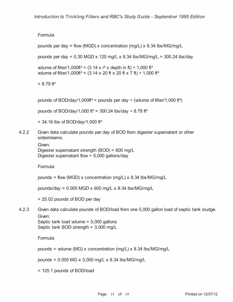
Given data calculate influent loading in pounds of BOD per day ÷ 1,000 cubic feet of media.
Introduction to Trickling Filters and RBC's Study Guide - September 1995 Edition
Printed on 12/07/12Page 15 of 19
Formula:
pounds per day = flow (MGD) x concentration (mg/L) x 8.34 lbs/MG/mg/L
pounds per day = 0.30 MGD x 120 mg/L x 8.34 lbs/MG/mg/L = 300.24 lbs/day
volume of filter/1,000ft³ = (3.14 x r² x depth in ft) ÷ 1,000 ft³volume of filter/1,000ft³ = (3.14 x 20 ft x 20 ft x 7 ft) ÷ 1,000 ft³
= 8.79 ft³
pounds of BOD/day/1,000ft³ = pounds per day ÷ (volume of filter/1,000 ft³)
pounds of BOD/day/1,000 ft³ = 300.24 lbs/day ÷ 8.79 ft³
= 34.16 lbs of BOD/day/1,000 ft³
Given:Digester supernatant strength (BOD) = 600 mg/LDigester supernatant flow = 5,000 gallons/day
Formula:
pounds = flow (MGD) x concentration (mg/L) x 8.34 lbs/MG/mg/L
pounds/day = 0.005 MGD x 600 mg/L x 8.34 lbs/MG/mg/L
= 25.02 pounds of BOD per day
Given:Septic tank load volume = 5,000 gallonsSeptic tank BOD strength = 3,000 mg/L
Formula:
pounds = volume (MG) x concentration (mg/L) x 8.34 lbs/MG/mg/L
pounds = 0.005 MG x 3,000 mg/L x 8.34 lbs/MG/mg/L
= 125.1 pounds of BOD/load
4.2.2
4.2.3
Given data calculate pounds per day of BOD from digester supernatant or other sidestreams.
Given data calculate pounds of BOD/load from one 5,000 gallon load of septic tank sludge.
Introduction to Trickling Filters and RBC's Study Guide - September 1995 Edition
Printed on 12/07/12Page 16 of 19
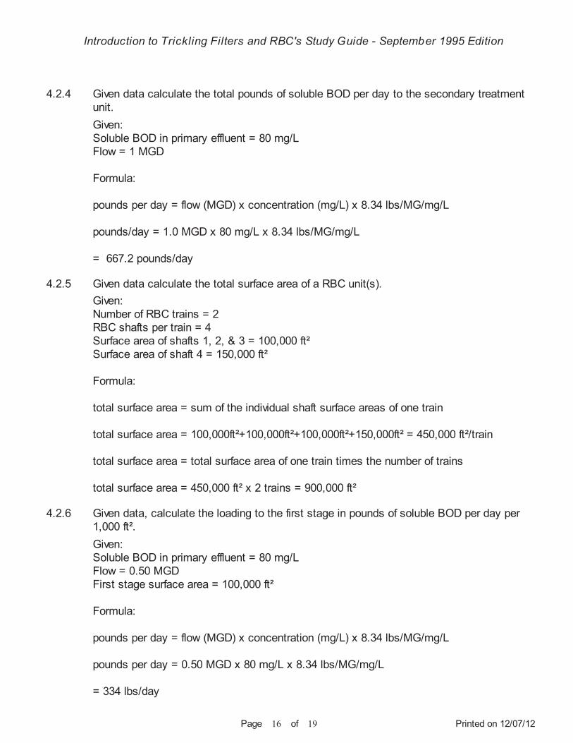
Given:Soluble BOD in primary effluent = 80 mg/LFlow = 1 MGD
Formula:
pounds per day = flow (MGD) x concentration (mg/L) x 8.34 lbs/MG/mg/L
pounds/day = 1.0 MGD x 80 mg/L x 8.34 lbs/MG/mg/L
= 667.2 pounds/day
Given:Number of RBC trains = 2RBC shafts per train = 4Surface area of shafts 1, 2, & 3 = 100,000 ft²Surface area of shaft 4 = 150,000 ft²
Formula:
total surface area = sum of the individual shaft surface areas of one train
total surface area = 100,000ft²+100,000ft²+100,000ft²+150,000ft² = 450,000 ft²/train
total surface area = total surface area of one train times the number of trains
total surface area = 450,000 ft² x 2 trains = 900,000 ft²
Given:Soluble BOD in primary effluent = 80 mg/LFlow = 0.50 MGDFirst stage surface area = 100,000 ft²
Formula:
pounds per day = flow (MGD) x concentration (mg/L) x 8.34 lbs/MG/mg/L
pounds per day = 0.50 MGD x 80 mg/L x 8.34 lbs/MG/mg/L
= 334 lbs/day
4.2.4
4.2.5
4.2.6
Given data calculate the total pounds of soluble BOD per day to the secondary treatment unit.
Given data calculate the total surface area of a RBC unit(s).
Given data, calculate the loading to the first stage in pounds of soluble BOD per day per 1,000 ft².
Introduction to Trickling Filters and RBC's Study Guide - September 1995 Edition
Printed on 12/07/12Page 17 of 19
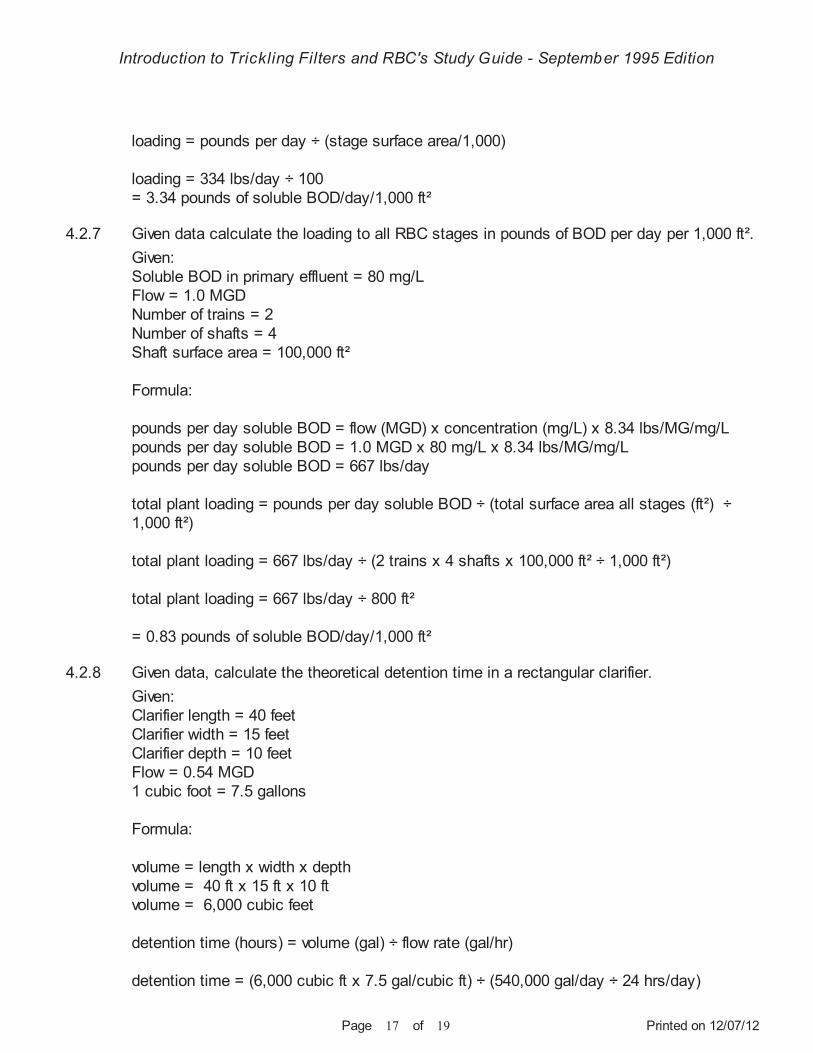
loading = pounds per day ÷ (stage surface area/1,000)
loading = 334 lbs/day ÷ 100 = 3.34 pounds of soluble BOD/day/1,000 ft²
Given:Soluble BOD in primary effluent = 80 mg/LFlow = 1.0 MGDNumber of trains = 2Number of shafts = 4Shaft surface area = 100,000 ft²
Formula:
pounds per day soluble BOD = flow (MGD) x concentration (mg/L) x 8.34 lbs/MG/mg/Lpounds per day soluble BOD = 1.0 MGD x 80 mg/L x 8.34 lbs/MG/mg/Lpounds per day soluble BOD = 667 lbs/day
total plant loading = pounds per day soluble BOD ÷ (total surface area all stages (ft²) ÷ 1,000 ft²)
total plant loading = 667 lbs/day ÷ (2 trains x 4 shafts x 100,000 ft² ÷ 1,000 ft²)
total plant loading = 667 lbs/day ÷ 800 ft²
= 0.83 pounds of soluble BOD/day/1,000 ft²
Given:Clarifier length = 40 feetClarifier width = 15 feetClarifier depth = 10 feetFlow = 0.54 MGD1 cubic foot = 7.5 gallons
Formula:
volume = length x width x depthvolume = 40 ft x 15 ft x 10 ftvolume = 6,000 cubic feet
detention time (hours) = volume (gal) ÷ flow rate (gal/hr)
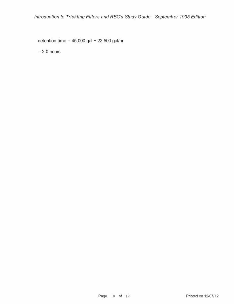
detention time = (6,000 cubic ft x 7.5 gal/cubic ft) ÷ (540,000 gal/day ÷ 24 hrs/day)
4.2.7
4.2.8
Given data calculate the loading to all RBC stages in pounds of BOD per day per 1,000 ft².
Given data, calculate the theoretical detention time in a rectangular clarifier.
Introduction to Trickling Filters and RBC's Study Guide - September 1995 Edition
Printed on 12/07/12Page 18 of 19
detention time = 45,000 gal ÷ 22,500 gal/hr
= 2.0 hours
Introduction to Trickling Filters and RBC's Study Guide - September 1995 Edition
Printed on 12/07/12Page 19 of 19
References and Resources
CONTROLLING WASTEWATER TREATMENT PROCESSES.
OPERATION OF MUNICIPAL WASTEWATER TREATMENT PLANTS.
OPERATION OF WASTEWATER TREATMENT PLANTS.
OPERATION OF WASTEWATER TREATMENT PLANTS.
(1984). Cortinovis, Dan. Ridgeline Press, 1136 Orchard Road, Lafayette, CA 94549.
Manual of Practice No. 11 (MOP 11), 2nd Edition (1990), Volumes I, II, and III. Water Environment Federation (Old WPCF), 601 Wythe Street, Alexandria, VA 22314-1994.Phone (800) 666-0206.
3rd Edition (1990), Volumes 1 and 2, Kenneth D. Kerri, California State University, 6000 J Street, Sacramento, CA 95819-6025. Phone (916) 278-6142.
Manual of Practice No. 11 (MOP 11) (1976). Water Pollution Control Federation, 601 Wythe Street, Alexandria, VA 22314-1994. Phone (800) 666-0206. (Probably Out-of-Print, See Reference Number 2)
http://www.wef.org/
http://www.owp.csus.edu/training/
http://www.wef.org/
1.
2.
3.
4.