Embed Size (px)
Citation preview
APT REPORT
On
PACKET TRANSPORT NETWORKS
No. APT/ASTAP/REPT-14Edition: August 2014
Source Document: ASTAP-24/OUT-16
Adopted by
The 24th APT Standardization Program Forum (ASTAP-24)27 – 29 August 2014, Bangkok, Thailand
APT/ASTAP/REPT-14
Table of contents
1 Introduction...............................................................................................................................42 Scope.........................................................................................................................................43 Abbreviations and acronyms.....................................................................................................44 Overview of MPLS-TP technology..........................................................................................55 OAM.........................................................................................................................................75.1 MIP/MEP in OAM....................................................................................................................75.2 OAM functions..........................................................................................................................96 Protection................................................................................................................................107 Standardization........................................................................................................................117.1 OAM specifications................................................................................................................127.2 Protection specifications.........................................................................................................138 Applications of MPLS-TP based packet transport network and future direction...................148.1 Migration of legacy network...................................................................................................148.2 Layer convergence..................................................................................................................158.3 Software defined network.......................................................................................................169 Conclusions.............................................................................................................................17
Page 2 of 16
APT/ASTAP/REPT-14
1 Introduction
Transport networks provide transparent transmission of client data traffic between connected client devices by establishing and maintaining point-to-point or point-to-multipoint connections between such devices. The network is basically independent of any higher-layer network that may exist between clients. In addition to client traffic, a transport network must carry traffic to facilitate its own operation that is necessary for connection control, operation, administration, and maintenance (OAM) functions, network management systems (NMSs), and protection, just as traditional dedicated circuit-based transport technologies such as synchronous digital hierarchy (SDH) and optical transport networks (OTNs), have satisfactory grade capabilities of these functions.
The number of Internet protocol (IP) services continues to increase drastically, and telecom carriers have been willing to efficiently accommodate their client traffic. Packet network technologies including Ethernet and multiprotocol label switching (MPLS) were introduced in response to such a demand; however, these did not have sufficient maintenance capabilities, so a new packet transport technology has been strongly demanded for telecom carrier networks.
A migration from a legacy network to a new packet transport network is one of the most serious issues for telecom carriers. The development of packet transport network technology has been aimed at achieving functionality similar to that of traditional transport networks achieved by SDH or OTN, which is used to accommodate legacy services including public switched telephone network (PSTN) lines, private leased lines, and clock signal paths. Thus, the packet transport network must efficiently accommodate IP-oriented services while retaining the existing services by replacing an existing legacy SDH-based transport network. Another issue in deploying a packet transport network is flexibility in introducing emerging new technologies such as software defined networking (SDN) and low cost L3 switch clustering.
2 Scope
This report gives an overview of the technology and standardization of packet transport networks based on MPLS-TP (Transport Profile) that have been developed to satisfy these demands described in clause 1 and reviews the future direction of transport network development.
3 Abbreviations and acronyms
AIS Alarm Indication SignalAPS Automatic Protection SwitchingCC Continuity CheckCFI Client Failure IndicationCSF Client Signal FailCV Connectivity VerificationDCC Data Communication ChannelDM Delay MeasurementDT Diagnostic TestEXP ExperimentalACH Associated Channel HeaderG-ACh Generic Associated ChannelGAL G-ACh LabelIANA Internet Assigned Numbers AuthorityIETF Internet Engineering Task ForceLCK locked SignalLER Label Edge RouterLM Loss MeasurementLOC Loss Of ContinuityLSP Label Switched Path
Page 3 of 16
APT/ASTAP/REPT-14
LSR Label Switch RouterME Maintenance EntityMEL MEG LevelMEG Maintenance Entity GroupMEP MEG End Point MIP MEG Intermediate PointMPLS Multi Protocol Label SwitchingMPLS-TP MPLS Transport ProfileNE Network ElementOAM Operation, Administration & MaintenanceOTN Optical Transport NetworkPD Packet DelayPDU Protocol Data UnitPDV Packet Delay VariationPHB Per-Hop Forwarding BehaviourPSN Packet Switched NetworkPW PseudoWirePWE3 PseudoWire Emulation Edge-to-EdgeRDI Remote Defect IndicationRFC Requests for CommentsSDH Synchronous Digital Herarchy
4 Overview of MPLS-TP technology
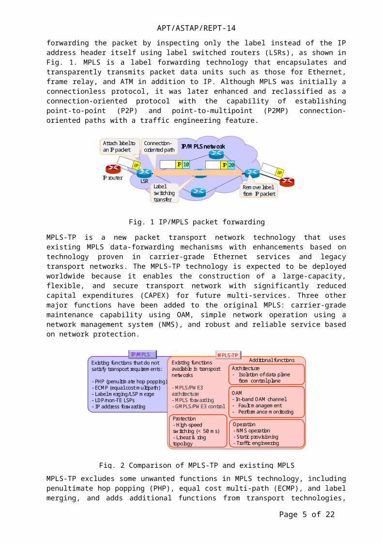
MPLS was developed to make it possible to explicitly determine the path route of IP packets by attaching a label to an IP packet and forwarding the packet by inspecting only the label instead of the IP address header itself using label switched routers (LSRs), as shown in Fig. 1. MPLS is a label forwarding technology that encapsulates and transparently transmits packet data units such as those for Ethernet, frame relay, and ATM in addition to IP. Although MPLS was initially a connectionless protocol, it was later enhanced and reclassified as a connection-oriented protocol with the capability of establishing point-to-point (P2P) and point-to-multipoint (P2MP) connection-oriented paths with a traffic engineering feature.
MPLS-TP is a new packet transport network technology that uses existing MPLS data-forwarding mechanisms with enhancements based on technology proven in carrier-grade Ethernet services and legacy transport networks. The MPLS-TP technology is expected to be deployed worldwide because it enables the construction of a large-capacity, flexible, and secure transport network with significantly reduced capital expenditures (CAPEX) for future multi-services. Three other major functions have been added to the original MPLS: carrier-grade maintenance capability using OAM, simple network operation using a network management system (NMS), and robust and reliable service based on network protection.
Page 4 of 16
IP/MPLS network
IP 20
Attach label to an IP packet
Label switching transfer
Remove label from IP packet
IP router LSR
Connection-oriented path
IP 10
Fig. 1 IP/MPLS packet forwarding
APT/ASTAP/REPT-14
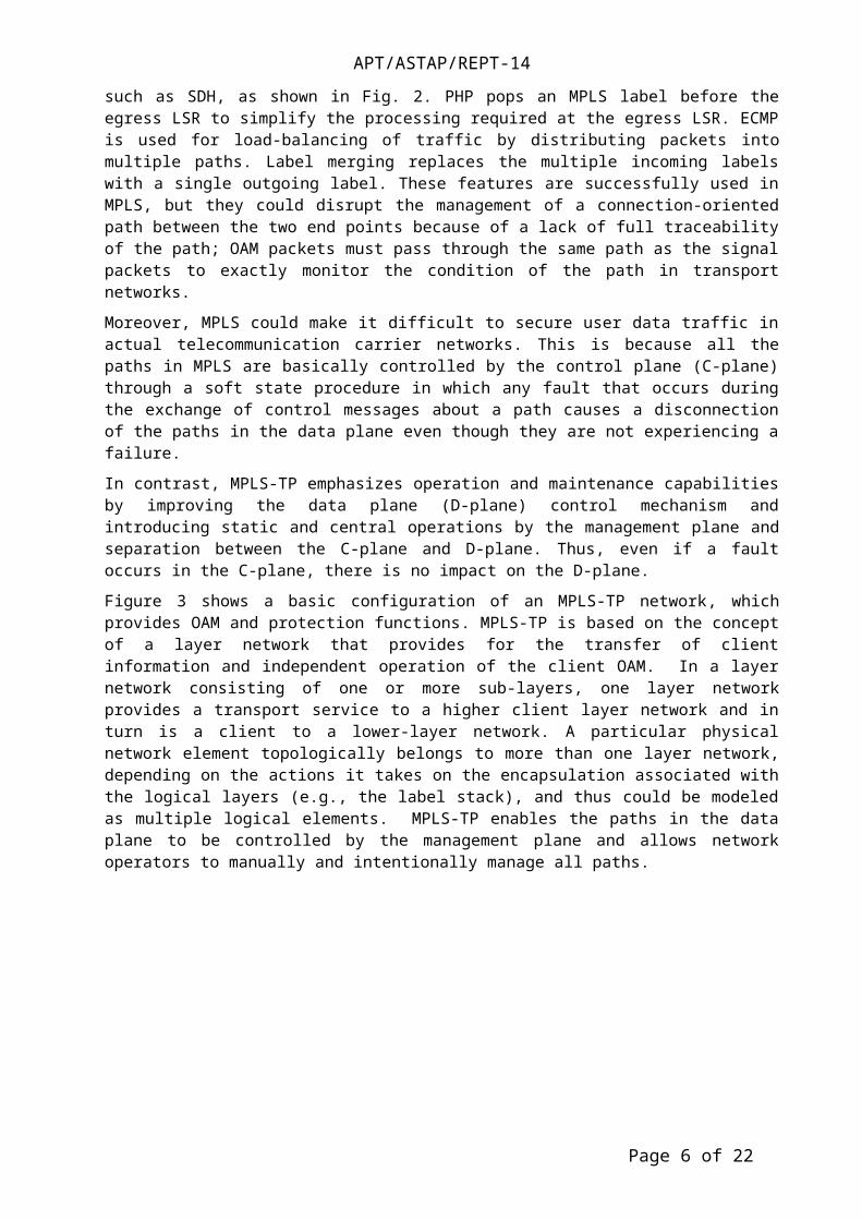
MPLS-TP excludes some unwanted functions in MPLS technology, including penultimate hop popping (PHP), equal cost multi-path (ECMP), and label merging, and adds additional functions from transport technologies, such as SDH, as shown in Fig. 2. PHP pops an MPLS label before the egress LSR to simplify the processing required at the egress LSR. ECMP is used for load-balancing of traffic by distributing packets into multiple paths. Label merging replaces the multiple incoming labels with a single outgoing label. These features are successfully used in MPLS, but they could disrupt the management of a connection-oriented path between the two end points because of a lack of full traceability of the path; OAM packets must pass through the same path as the signal packets to exactly monitor the condition of the path in transport networks.
Moreover, MPLS could make it difficult to secure user data traffic in actual telecommunication carrier networks. This is because all the paths in MPLS are basically controlled by the control plane (C-plane) through a soft state procedure in which any fault that occurs during the exchange of control messages about a path causes a disconnection of the paths in the data plane even though they are not experiencing a failure.
In contrast, MPLS-TP emphasizes operation and maintenance capabilities by improving the data plane (D-plane) control mechanism and introducing static and central operations by the management plane and separation between the C-plane and D-plane. Thus, even if a fault occurs in the C-plane, there is no impact on the D-plane.
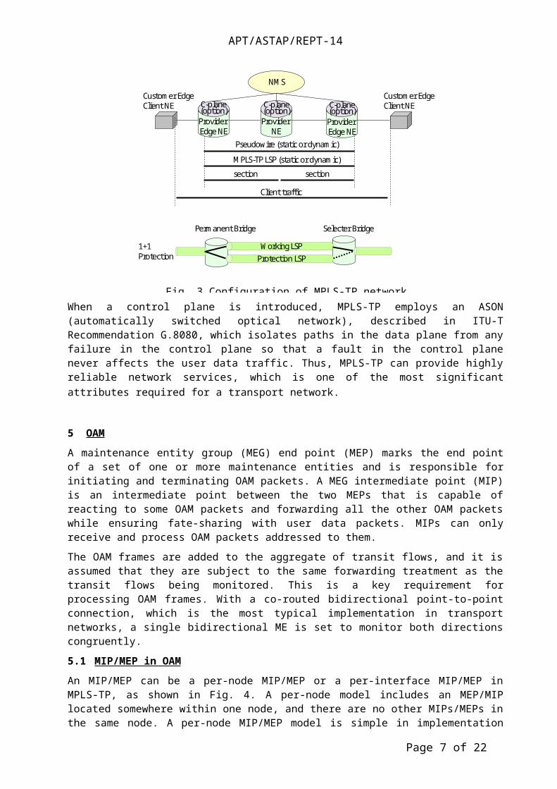
Figure 3 shows a basic configuration of an MPLS-TP network, which provides OAM and protection functions. MPLS-TP is based on the concept of a layer network that provides for the transfer of client information and independent operation of the client OAM. In a layer network consisting of one or more sub-layers, one layer network provides a transport service to a higher client layer network and in turn is a client to a lower-layer network. A particular physical network element topologically belongs to more than one layer network, depending on the actions it takes on the encapsulation associated with the logical layers (e.g., the label stack), and thus could be modeled as multiple logical elements. MPLS-TP enables the paths in the data plane to be controlled by the management plane and allows network operators to manually and intentionally manage all paths.
Page 5 of 16
Existing functions that do not satisfy transport requirements:
- PHP (penultimate hop popping)- ECMP (equal cost multipath)- Label merging/LSP merge- LDP/non-TE LSPs- IP address forwarding
Existing functions available in transport networks
- MPLS/PWE3architecture- MPLS forwarding- GMPLS/PWE3 control
OAM- In-band OAM channel- Fault management- Performance monitoring
Protection- High-speed switching (< 50 ms)- Linear & ring topology
Operation- NMS operation- Static provisioning- Traffic engineering
IP/MPLS MPLS-TPAdditional functions
Architecture- Isolation of data plane
from control plane
Fig. 2 Comparison of MPLS-TP and existing MPLS
APT/ASTAP/REPT-14
When a control plane is introduced, MPLS-TP employs an ASON (automatically switched optical network), described in ITU-T Recommendation G.8080, which isolates paths in the data plane from any failure in the control plane so that a fault in the control plane never affects the user data traffic. Thus, MPLS-TP can provide highly reliable network services, which is one of the most significant attributes required for a transport network.
5 OAM
A maintenance entity group (MEG) end point (MEP) marks the end point of a set of one or more maintenance entities and is responsible for initiating and terminating OAM packets. A MEG intermediate point (MIP) is an intermediate point between the two MEPs that is capable of reacting to some OAM packets and forwarding all the other OAM packets while ensuring fate-sharing with user data packets. MIPs can only receive and process OAM packets addressed to them.
The OAM frames are added to the aggregate of transit flows, and it is assumed that they are subject to the same forwarding treatment as the transit flows being monitored. This is a key requirement for processing OAM frames. With a co-routed bidirectional point-to-point connection, which is the most typical implementation in transport networks, a single bidirectional ME is set to monitor both directions congruently.
5.1 MIP/MEP in OAM
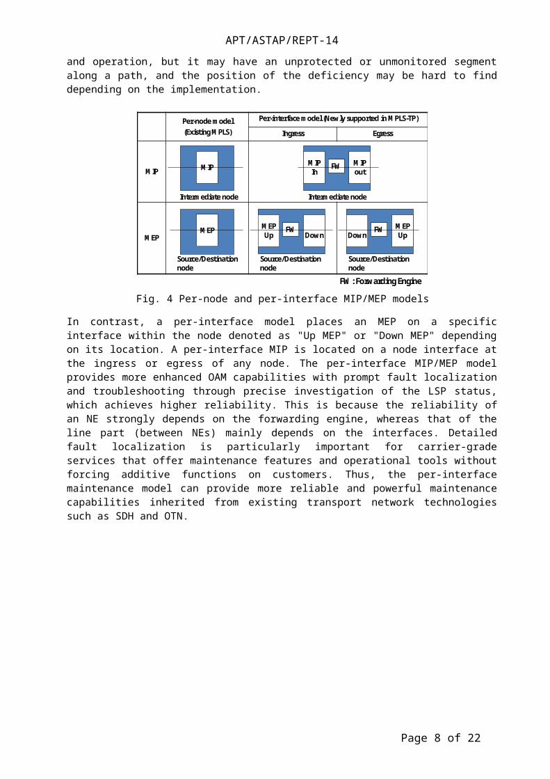
An MIP/MEP can be a per-node MIP/MEP or a per-interface MIP/MEP in MPLS-TP, as shown in Fig. 4. A per-node model includes an MEP/MIP located somewhere within one node, and there are no other MIPs/MEPs in the same node. A per-node MIP/MEP model is simple in implementation and operation, but it may have an unprotected or unmonitored segment along a path, and the position of the deficiency may be hard to find depending on the implementation.
Page 6 of 16
Provider Edge NE
NMS
Pseudowire (static or dynamic)
MPLS-TP LSP (static or dynamic)
section section
Client traffic
Provider Edge NE
1+1Protection
Working LSPProtection LSP
Permanent Bridge Selecter Bridge
Customer EdgeClient NE C-plane
(option)C-plane(option)
Provider NE
C-plane(option)
Customer EdgeClient NE
Fig. 3 Configuration of MPLS-TP network
APT/ASTAP/REPT-14
In contrast, a per-interface model places an MEP on a specific interface within the node denoted as "Up MEP" or "Down MEP" depending on its location. A per-interface MIP is located on a node interface at the ingress or egress of any node. The per-interface MIP/MEP model provides more enhanced OAM capabilities with prompt fault localization and troubleshooting through precise investigation of the LSP status, which achieves higher reliability. This is because the reliability of an NE strongly depends on the forwarding engine, whereas that of the line part (between NEs) mainly depends on the interfaces. Detailed fault localization is particularly important for carrier-grade services that offer maintenance features and operational tools without forcing additive functions on customers. Thus, the per-interface maintenance model can provide more reliable and powerful maintenance capabilities inherited from existing transport network technologies such as SDH and OTN.
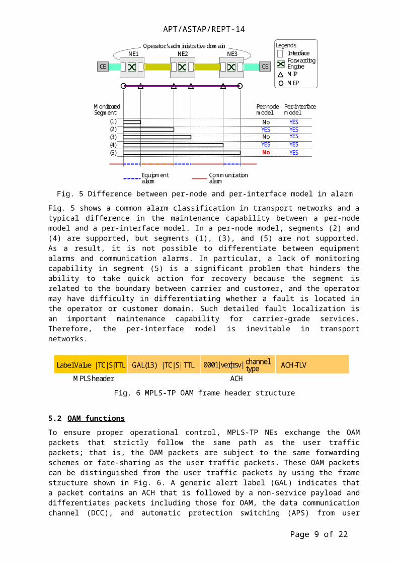
Fig. 5 shows a common alarm classification in transport networks and a typical difference in the maintenance capability between a per-node model and a per-interface model. In a per-node model, segments (2) and (4) are supported, but segments (1), (3), and (5) are not supported. As a result, it is not possible to differentiate between equipment alarms and communication alarms. In particular, a lack of monitoring capability in segment (5) is a significant problem that hinders the ability to take quick action for recovery because the segment is related to the boundary between carrier and customer, and the operator may have difficulty in differentiating whether a fault is located in the operator or customer domain. Such detailed fault localization is an important maintenance capability for carrier-grade services. Therefore, the per-interface model is inevitable in transport networks.
Page 7 of 16
Per-node model(Existing MPLS)
Per-interface model (Newly supported in MPLS-TP)
Ingress Egress
MIP
MEP
MIP
Source/Destination node
MEP
Intermediate node
MIPout
MIPIn
FW
DownMEPUp
FW MEPUpDown
FW
Intermediate node
Source/Destination node
Source/Destination node
FW: Forwarding Engine
Fig. 4 Per-node and per-interface MIP/MEP models
MonitoredSegment
(1)(2)(3)(4)(5)
Per-nodemodel
MIPMEP
LegendsInterfaceForwardingEngine
NE2 NE3NE1
Equipmentalarm
Communicationalarm
Per-interfacemodel
YESYESYESYESYES
YES
YES
No
No
No
CE CE
Operator’s administrative domain
Fig. 5 Difference between per-node and per-interface model in alarm classification
APT/ASTAP/REPT-14
5.2 OAM functions
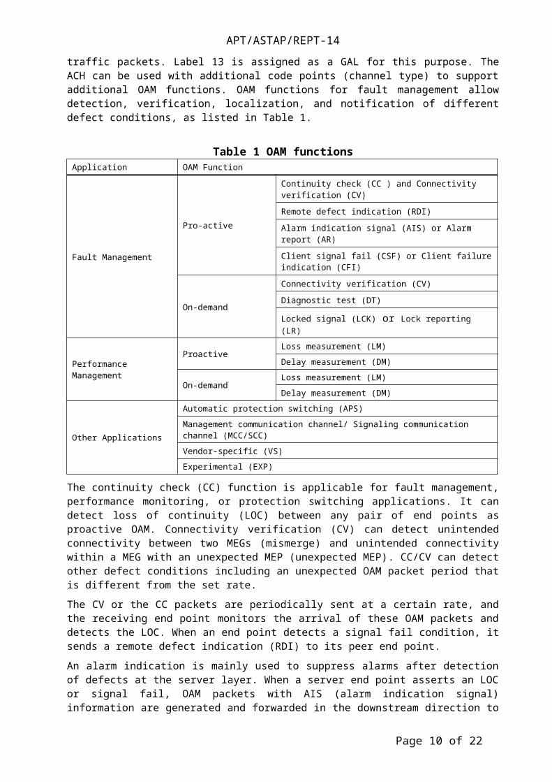
To ensure proper operational control, MPLS-TP NEs exchange the OAM packets that strictly follow the same path as the user traffic packets; that is, the OAM packets are subject to the same forwarding schemes or fate-sharing as the user traffic packets. These OAM packets can be distinguished from the user traffic packets by using the frame structure shown in Fig. 6. A generic alert label (GAL) indicates that a packet contains an ACH that is followed by a non-service payload and differentiates packets including those for OAM, the data communication channel (DCC), and automatic protection switching (APS) from user traffic packets. Label 13 is assigned as a GAL for this purpose. The ACH can be used with additional code points (channel type) to support additional OAM functions. OAM functions for fault management allow detection, verification, localization, and notification of different defect conditions, as listed in Table 1.
Table 1 OAM functionsApplication OAM Function
Fault Management
Pro-active
Continuity check (CC ) and Connectivity verification (CV)
Remote defect indication (RDI)
Alarm indication signal (AIS) or Alarm report (AR)
Client signal fail (CSF) or Client failure indication (CFI)
On-demand
Connectivity verification (CV)
Diagnostic test (DT)
Locked signal (LCK) or Lock reporting (LR)
Performance Management
ProactiveLoss measurement (LM)
Delay measurement (DM)
On-demandLoss measurement (LM)
Delay measurement (DM)
Other Applications
Automatic protection switching (APS)
Management communication channel/ Signaling communication channel (MCC/SCC)
Vendor-specific (VS)
Experimental (EXP)
The continuity check (CC) function is applicable for fault management, performance monitoring, or protection switching applications. It can detect loss of continuity (LOC) between any pair of end points as proactive OAM. Connectivity verification (CV) can detect unintended connectivity between two MEGs (mismerge) and unintended connectivity within a MEG with an unexpected MEP (unexpected MEP). CC/CV can detect other defect conditions including an unexpected OAM packet period that is different from the set rate.
The CV or the CC packets are periodically sent at a certain rate, and the receiving end point monitors the arrival of these OAM packets and detects the LOC. When an end point detects a signal fail condition, it sends a remote defect indication (RDI) to its peer end point.
An alarm indication is mainly used to suppress alarms after detection of defects at the server layer. When a server end point asserts an LOC or signal fail, OAM packets with AIS (alarm indication signal) information are generated and forwarded in the downstream direction to the peer end point in the client layer, which allows the suppression of secondary alarms (e.g., LOC) in the client (sub-) layer.
Page 8 of 16
Label Value |TC|S|TTL GAL(13) |TC|S| TTL 0001|ver |rsv| channel type
MPLS header ACH
ACH-TLV
Fig. 6 MPLS-TP OAM frame header structure
APT/ASTAP/REPT-14
A client signal fail (CSF) is used to process client defects and propagate a client signal defect to the associated remote end point. This function is usually used when the client of the MPLS-TP network does not support a native defect/alarm indication mechanism such as AIS. The CSF propagates an indication that a failure of the ingress client signal has been detected.
The diagnostic test (DT) function is used to perform diagnostic tests such as bandwidth throughput, packet loss, and bit error estimation by sending OAM diagnostic test packets.
A proactive loss measurement (LM) function is used to verify the performance of a connection against the service level agreement (SLA) and to measure packet loss on the connection. An on-demand LM function is used to measure packet loss on a connection for maintenance purposes. It is performed during a specific time interval, and its result can be used for diagnosis and analysis.
An on-demand delay measurement (DM) function is used to measure packet delay and packet delay variations on a connection. Automatic protection switching (APS) communications allow MPLS-TP nodes to exchange protection switching control.
6 Protection
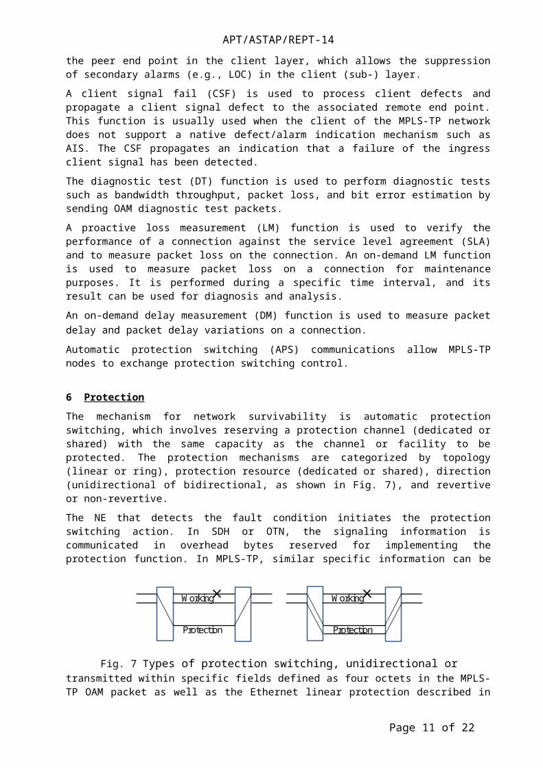
The mechanism for network survivability is automatic protection switching, which involves reserving a protection channel (dedicated or shared) with the same capacity as the channel or facility to be protected. The protection mechanisms are categorized by topology (linear or ring), protection resource (dedicated or shared), direction (unidirectional of bidirectional, as shown in Fig. 7), and revertive or non-revertive.
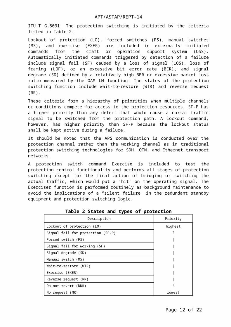
The NE that detects the fault condition initiates the protection switching action. In SDH or OTN, the signaling information is communicated in overhead bytes reserved for implementing the protection function. In MPLS-TP, similar specific information can be transmitted within specific fields defined as four octets in the MPLS-TP OAM packet as well as the Ethernet linear protection described in ITU-T G.8031. The protection switching is initiated by the criteria listed in Table 2.
Lockout of protection (LO), forced switches (FS), manual switches (MS), and exercise (EXER) are included in externally initiated commands from the craft or operation support system (OSS). Automatically initiated commands triggered by detection of a failure include signal fail (SF) caused by a loss of signal (LOS), loss of framing (LOF), or an excessive bit error rate (BER), and signal degrade (SD) defined by a relatively high BER or excessive packet loss ratio measured by the OAM LM function. The states of the protection switching function include wait-to-restore (WTR) and reverse request (RR). These criteria form a hierarchy of priorities when multiple channels or conditions compete for access to the protection resources. SF-P has a higher priority than any defect that would cause a normal traffic signal to be switched from the protection path. A lockout command, however, has higher priority than SF-P because the lockout status shall be kept active during a failure.
It should be noted that the APS communication is conducted over the protection channel rather than the working channel as in traditional protection switching technologies for SDH, OTN, and Ethernet transport networks.
A protection switch command Exercise is included to test the protection control functionality and performs all stages of protection switching except for the final action of bridging or switching the actual traffic, which would put a ‘hit’ on the operating signal. The Exerciser function is performed routinely as
Page 9 of 16
Working
Protection
Working
Protection
Fig. 7 Types of protection switching, unidirectional or bidirectional.
APT/ASTAP/REPT-14
background maintenance to avoid the implications of a “silent failure” in the redundant standby equipment and protection switching logic.
Table 2 States and types of protectionDescription Priority
Lockout of protection (LO) highest
Signal fail for protection (SF-P)
Forced switch (FS) |
Signal fail for working (SF) |
Signal degrade (SD) |
Manual switch (MS) |
Wait-to-restore (WTR) |
Exercise (EXER) |
Reverse request (RR) |
Do not revert (DNR)
No request (NR) lowest
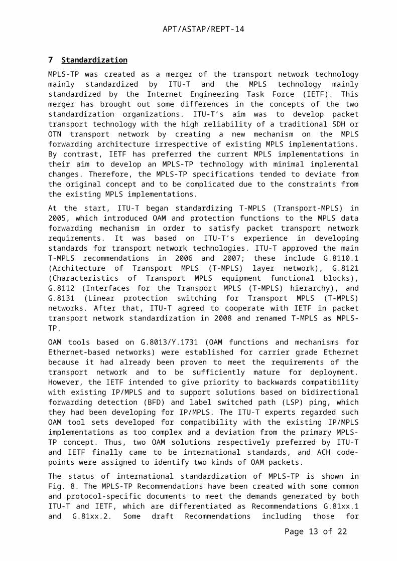
7 Standardization
MPLS-TP was created as a merger of the transport network technology mainly standardized by ITU-T and the MPLS technology mainly standardized by the Internet Engineering Task Force (IETF). This merger has brought out some differences in the concepts of the two standardization organizations. ITU-T’s aim was to develop packet transport technology with the high reliability of a traditional SDH or OTN transport network by creating a new mechanism on the MPLS forwarding architecture irrespective of existing MPLS implementations. By contrast, IETF has preferred the current MPLS implementations in their aim to develop an MPLS-TP technology with minimal implemental changes. Therefore, the MPLS-TP specifications tended to deviate from the original concept and to be complicated due to the constraints from the existing MPLS implementations.
At the start, ITU-T began standardizing T-MPLS (Transport-MPLS) in 2005, which introduced OAM and protection functions to the MPLS data forwarding mechanism in order to satisfy packet transport network requirements. It was based on ITU-T’s experience in developing standards for transport network technologies. ITU-T approved the main T-MPLS recommendations in 2006 and 2007; these include G.8110.1 (Architecture of Transport MPLS (T-MPLS) layer network), G.8121 (Characteristics of Transport MPLS equipment functional blocks), G.8112 (Interfaces for the Transport MPLS (T-MPLS) hierarchy), and G.8131 (Linear protection switching for Transport MPLS (T-MPLS) networks. After that, ITU-T agreed to cooperate with IETF in packet transport network standardization in 2008 and renamed T-MPLS as MPLS-TP.
OAM tools based on G.8013/Y.1731 (OAM functions and mechanisms for Ethernet-based networks) were established for carrier grade Ethernet because it had already been proven to meet the requirements of the transport network and to be sufficiently mature for deployment. However, the IETF intended to give priority to backwards compatibility with existing IP/MPLS and to support solutions based on bidirectional forwarding detection (BFD) and label switched path (LSP) ping, which they had been developing for IP/MPLS. The ITU-T experts regarded such OAM tool sets developed for compatibility with the existing IP/MPLS implementations as too complex and a deviation from the primary MPLS-TP concept. Thus, two OAM solutions respectively preferred by ITU-T and IETF finally came to be international standards, and ACH code-points were assigned to identify two kinds of OAM packets.
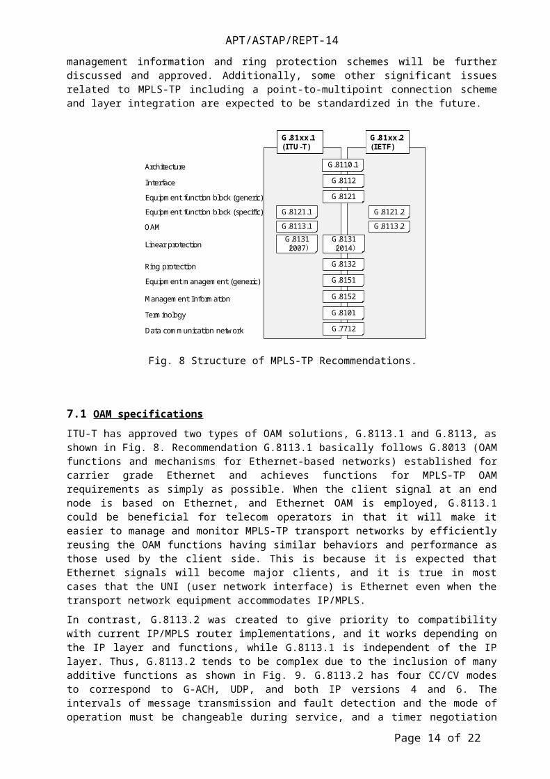
The status of international standardization of MPLS-TP is shown in Fig. 8. The MPLS-TP Recommendations have been created with some common and protocol-specific documents to meet the demands generated by both ITU-T and IETF, which are differentiated as Recommendations G.81xx.1 and G.81xx.2. Some draft Recommendations including those for management information and ring protection schemes will be further discussed and approved. Additionally, some other significant issues
Page 10 of 16
APT/ASTAP/REPT-14
related to MPLS-TP including a point-to-multipoint connection scheme and layer integration are expected to be standardized in the future.
7.1 OAM specifications
ITU-T has approved two types of OAM solutions, G.8113.1 and G.8113, as shown in Fig. 8. Recommendation G.8113.1 basically follows G.8013 (OAM functions and mechanisms for Ethernet-based networks) established for carrier grade Ethernet and achieves functions for MPLS-TP OAM requirements as simply as possible. When the client signal at an end node is based on Ethernet, and Ethernet OAM is employed, G.8113.1 could be beneficial for telecom operators in that it will make it easier to manage and monitor MPLS-TP transport networks by efficiently reusing the OAM functions having similar behaviors and performance as those used by the client side. This is because it is expected that Ethernet signals will become major clients, and it is true in most cases that the UNI (user network interface) is Ethernet even when the transport network equipment accommodates IP/MPLS.
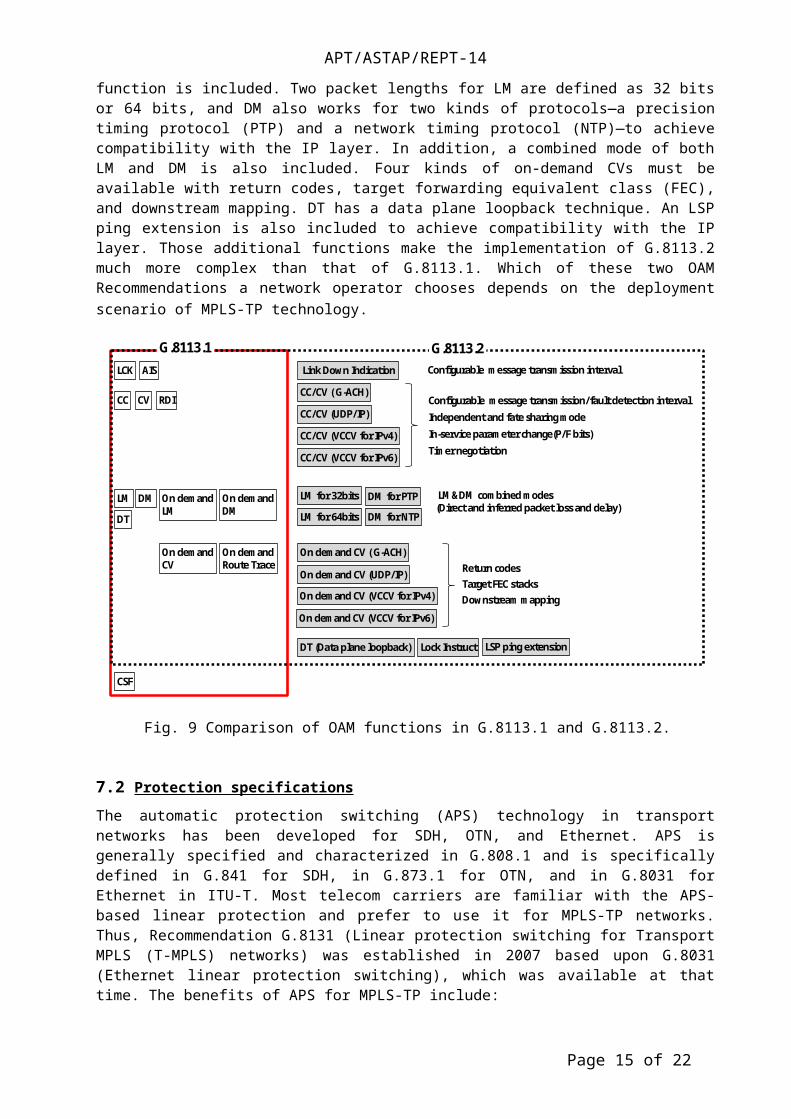
In contrast, G.8113.2 was created to give priority to compatibility with current IP/MPLS router implementations, and it works depending on the IP layer and functions, while G.8113.1 is independent of the IP layer. Thus, G.8113.2 tends to be complex due to the inclusion of many additive functions as shown in Fig. 9. G.8113.2 has four CC/CV modes to correspond to G-ACH, UDP, and both IP versions 4 and 6. The intervals of message transmission and fault detection and the mode of operation must be changeable during service, and a timer negotiation function is included. Two packet lengths for LM are defined as 32 bits or 64 bits, and DM also works for two kinds of protocols—a precision timing protocol (PTP) and a network timing protocol (NTP)—to achieve compatibility with the IP layer. In addition, a combined mode of both LM and DM is also included. Four kinds of on-demand CVs must be available with return codes, target forwarding equivalent class (FEC), and downstream mapping. DT has a data plane loopback technique. An LSP ping extension is also included to achieve compatibility with the IP layer. Those additional functions make the implementation of G.8113.2 much more complex than that of G.8113.1. Which of these two OAM Recommendations a network operator chooses depends on the deployment scenario of MPLS-TP technology.
Page 11 of 16
ArchitectureInterface
OAM
Linear protection
Ring protection
G.8112
G.8113.1 G.8113.2
G.8121Equipment function block (generic)
Management Information
G.8132G.8151
G.8152
G.81xx.1(ITU-T)
G.81xx.2(IETF)
Terminology G.8101G.7712Data communication network
Equipment function block (specific) G.8121.1 G.8121.2
G.8110.1
G.8131(2014)
Equipment management (generic)
G.8131(2007)
Fig. 8 Structure of MPLS-TP Recommendations.
APT/ASTAP/REPT-14
7.2 Protection specifications
The automatic protection switching (APS) technology in transport networks has been developed for SDH, OTN, and Ethernet. APS is generally specified and characterized in G.808.1 and is specifically defined in G.841 for SDH, in G.873.1 for OTN, and in G.8031 for Ethernet in ITU-T. Most telecom carriers are familiar with the APS-based linear protection and prefer to use it for MPLS-TP networks. Thus, Recommendation G.8131 (Linear protection switching for Transport MPLS (T-MPLS) networks) was established in 2007 based upon G.8031 (Ethernet linear protection switching), which was available at that time. The benefits of APS for MPLS-TP include:
•Technical maturity and stability are mandatory for protection switching schemes because protection switching has a direct and significant impact on the reliability and quality of services for telecommunication operators. APS linear protection is a highly mature solution as a result of improvements, verifications, and tests that have been done over the years through many implementations and thousands of deployments both in circuit (SDH, OTN) and packet (Ethernet)-based networks. In particular, the APS mechanism used for MPLS-TP completely follows that of Ethernet linear protection (G.8031) developed in ITU-T.
•MPLS-TP OAM Recommendation G.8113.1 follows Ethernet OAM G.8013/Y.1731 and thus specifies that OAM should be able to operate with the APS protocol.
•Consistency with existing transport technologies enables operational savings because no specific retraining is required, and human error can be avoided. Furthermore, such consistency between the different technologies/layers is beneficial in future multi-layer and multi-technology converged networks and will ease the protection interworking issues between technologies/layers.
In the meantime, the IETF developed another MPLS-TP linear protection scheme, called protection state coordination (PSC), as specified in RFC 6378. The differences between APS and PSC are their operational behavior as well as frame format. Operational experience in SDH/OTN/Ethernet is reflected in APS, but PSC changed some operational functions including the priority levels of various protection switching triggers, and this could affect the operator’s maintenance abilities in transport networks.
Page 12 of 16
Independent and fate sharing mode
Link Down Indication
Configurable message transmission/fault detection interval
Timer negotiationIn-service parameter change(P/F bits)
Configurable message transmission interval
LM&DM combined modes (Direct and inferred packet loss and delay)
LM for 32bits DM for PTP
On demand CV ( G-ACH)Return codesTarget FEC stacksDownstream mapping
LSP ping extension
CC
On demandCV
RDI
AIS
On demandDM
On demandLM
On demandRoute Trace
LCK
CSF
DT (Data plane loopback)
CV
DMLM
Lock Instruct
DT
G.8113.1 G.8113.2
On demand CV (UDP/IP)
On demand CV (VCCV for IPv6)
CC/CV ( G-ACH)
CC/CV (UDP/IP)
CC/CV (VCCV for IPv6)
CC/CV (VCCV for IPv4)
LM for 64bits DM for NTP
On demand CV (VCCV for IPv4)
Fig. 9 Comparison of OAM functions in G.8113.1 and G.8113.2.
APT/ASTAP/REPT-14
The SF-P is assigned a higher priority than FS in APS, but the priority is reversed in PSC. This means that care must be taken when the traffic is moved from the working path to a protection path for any reason. A forced switch (FS) command is mainly used for maintenance work. If an operator shuts down an LSP on the protection path by mistake, for example, by unplugging a fiber connector, the client traffic is automatically saved in the APS because SF-P has a higher priority than FS. However, the client traffic is not automatically recovered and is lost until the switching is manually executed in PSC (See Fig. 10).
Other different points in PSC include the lack of an EXER command and triggering by SD. An EXER command is issued to test the APS communication to determine whether it is operating correctly; an operator can check both the APS process logic and APS channel on the protection path. In PSC, it is assumed that such a test should be supported using Lockout of Protection or FS, and the traffic cannot be recovered when a fault occurs during an exercise operation. While there is a lot of discussion about how SD in packet networks should be defined, and there is no existing standard, operators can utilize SD as a trigger of protection switching based on their own definitions in APS. Non-revertive operation in APS is independent of protection switching triggers such as a fault, operator command FS, and MS. In contrast, it is adopted only when protection switching is triggered by a fault in PSC.
To improve the operation of traditional transport networks such as SDH, OTN, and Ethernet transport networks, the ITU-T has prepared a new Recommendation G.8131 (2014) that defines a protocol similar to APS and allows coexistence of the G.8113.1 based frame format and the PSC based frame format. When the frame formats of both G.8131 (2007) and of G.8131 (2014) are present in an operator’s network, these frame formats are sufficiently different to allow detection of any network misconfiguration.
8 Applications of MPLS-TP based packet transport network and future direction
8.1 Migration of legacy network
The packet transport network technology has been developed with the objective of achieving functionality similar to that of traditional transport networks achieved by SDH or OTN, which are based on dedicated-circuit switching technology, and that accommodates legacy services including PSTN (public switched telephone network) lines, private leased lines, and clock signal paths through high-speed transmission lines at bitrates of several tens of gigabits per second over long distances. As network facilities age, migration to new networks that can accommodate existing services is one of the most serious issues telecom carriers face. A migration from an SDH-based network to a new packet transport network is illustrated in Fig. 11.
The packet transport network should efficiently accommodate new IP-oriented services while retaining the existing services, as it is expected to replace an existing SDH-based transport network. One of the most significant features of the dedicated-circuit network is that each signal path is exclusively established before the service; i.e., it is connection-oriented. The quality of each service is always closely monitored, and information on alarm signals and failures is transmitted to each end of the network elements (NEs) so they can be managed by the network operator. Another feature includes the signal path protection functionality that enables prompt recovery of a service when one of the signal paths is blocked by a failure. Such a dedicated-circuit network, however, has a drawback in its efficiency of accommodating transmission capacity with the increase in IP-based services. This is because the IP
Page 13 of 16
Stay on protection path
Working path
Protection path
Unplugged fiber
Working path
Protection path
Automaticswitch back to working path
Unplugged fiber
(a) APS (b) PSCFig. 10 Comparison of operational behavior between APS and PSC
APT/ASTAP/REPT-14
signal is conveyed by packets that pass through the network only during a certain time interval and do not always occupy a transport path.
Consequently, packet transport technologies that can accommodate client data more efficiently and cost-effectively are in great demand for telecom carrier networks. Multi-service capability is achieved by accommodating various clients including Ethernet, SDH, plesiochronous digital hierarchy (PDH), and asynchronous transfer mode (ATM). They can be applied into any part of a network from the access, metro/aggregation, and core areas. In addition to the requirements described above, reducing CAPEX, operational expenditures (OPEX), and power consumption are important issues for telecom carriers. In addition to circuit emulation services, packet transport networks are required to retain clock signal paths for network synchronization.
The MPLS-TP network, in particular, the one based on G.8xx.1, is suitable for such a legacy network migration because it was created to be compatible with traditional transport networks achieved by SDH, OTN, or carrier-grade Ethernet.
8.2 Layer convergence
MPLS-TP can be a useful key technology for future packet optical converged transport (POT) networks that are expected to achieve lower equipment cost and power consumption, and simple multi-layer operation. The current or legacy networks have a mix of simple rings consisting of optical add/drop multiplexers (OADMs) or a multi-service provision platform (MSPP), and a point-to-point configuration connected by 10-Gb/s or 40-Gb/s dense wavelength division multiplexing (DWDM) lines to cover metro and core network areas, as shown in Fig. 12.
Without basic network configuration change, the POTs will replace these discrete DWDM, MSPP, and OADM systems with a converged one. This will enable a significant reduction in equipment cost due to the decreasing number of interface cards connecting these different kinds of NEs, simplifying NE operation systems, and cutting through some intermediate core routers. Packet switching based on MPLS-TP will result in flexible and bandwidth-efficient path services with highly reliable maintenance capabilities using very substantial OAM functions, the same as with SDH or OTN. Further cost reduction will also be expected by substantially reducing the number of relaying routers by introducing MPLS-TP packet switching (core router cut-through).
Another flexible switching function in the POTs works in the photonic layer, i.e., lambda switching. The lambda switching function included in POTs can efficiently and cost-effectively re-route large-capacity traffic at a wavelength unit onto many routes, while a legacy photonic network uses an OADM with fixed
Page 14 of 16
LegacyService
LegacyService
Legacyservice
Legacyservice
IP-basedservice
IP-based service
CSM CSM
PSTNDedicated line
LegacySDH
Clock path
Fixed serviceMobile service
Migration
Packet transportnetwork
CSM CSM
PSTNDedicated line
Clock path
CSM: Clock Supply Module
Fig. 11 Migration of a legacy network to packet transport network
APT/ASTAP/REPT-14
direction and wavelength position at a port. This configuration requires a local labor force for doing such tasks as package mounting and wiring when we change the direction or wavelength of the signal transmission. There may be sufficient time for this in normal planned operations, but we may have to quickly change the recovery paths from a failure or disaster. Instead, the POTs introduce colorless and directionless switching, as well as wavelength-tunable transponders for eliminating these kinds of restrictions in setting optical paths. We do not need a local labor force because the photonic switch can freely change the direction and color of the signal wavelength at any node. A more intelligent operation system, connected to the design system, will ease network operation even during multiple failures.
In legacy configurations, various NMSs, EMSs, and manual designs have been implemented in several layers and domains. In contrast, network operators can efficiently and simply set a path for client equipment and utilize efficient fault localization in such multi-layer converged networks because management is done through the unified NMS and topology-free flat transport network configuration, although the degree of improvement may depend on the current network structure of each operator. The inter-layer (or inter-protocol) relationship of OAM is also a significant key in reducing fault detection, localization, and fixing time through actions that include inhibiting alarm storms and quick recovery of efficient AISs.
8.3 Software defined network
The increasing demand for telecommunications networks that can flexibly offer large-capacity traffic for the rapidly changing business needs at a flat or reduced cost has resulted in the need for a new network technology. The concept of a software defined network (SDN) is based on such a flexible network that is programmable by software and can virtually create any network functions flexibly on demand. The key points in the SDN architecture include:
•Centralized network control
•Decoupling of the control and data planes
•Abstraction of the underlying network infrastructure for the applications
•Open interface connection of the multi-vendor network infrastructure components such as “open flow”
Such SDNs have been developed for enterprise applications and successfully installed in data center networks to accommodate the rapidly increasing data traffic for cloud services. One problem in deploying such SDN technology into a telecom carrier network is a difference in the scale of the network, including the number of nodes and links and the distance between network components. Another is the migration from the current network configuration to an SDN based network.
Page 15 of 16
DWDM
DWDMPOTS
DWDM
DWDM
OADM OADM
OADM OADM
OADM OADM
OADM OADM
POTS
POTS POTS
POTS POTS
POTS POTS
OperatorOperator 1
Operator 2
Fig. 12 Configuration and operation in a legacy and packet optical transport network.
APT/ASTAP/REPT-14
Figure 13 compares the layer architecture between an IP/MPLS based network (G.81xx.2) and an MPLS-TP based packet transport network (G.81xx.1). An IP/MPLS based network has a distributed control plane that controls both IP and MPLS/MPLS-TP layers and successfully contributes to IP network operation through its traffic engineering capabilities and many other features. However, integration of the control plane and data plane strongly depends on the vendor specifications and could make it difficult to deploy the SDN technology. In contrast, an MPLS-TP based packet transport network has a layer architecture that completely separates the date plane from the control plane and facilitates the introduction of SDN technology to any layer independently, for example, to layer 3 and the lower transport layer. Separation of the IP layer also enables us to introduce the clustering L3 switches that have recently been developed for L3 switching in data center networks at a drastically lower cost.
Transport SDN or SDTN (software defined transport network) is a subset of SDN architecture functions comprising the relevant SDN architecture components–the data plane, control and management planes, and the orchestrator. The purpose of the application of SDN for transport networks is to:
•Provide enhanced support for connection control in multi-domain, multi-technology, multi-layer, and multi-vendor transport networks, including network virtualization and network optimization;
•Enable technology-agnostic control of connectivity and the necessary support functions across multi-layer transport networks, facilitating optimization across circuit and packet layers; and
•Support the ability to deploy third-party applications.
ITU-T and other standardization organizations are now proceeding with the development of SDTN standardization.
9 Conclusions
The increasing demand for highly reliable and large-capacity packet transport technology has facilitated the development of MPLS-TP technology. The key features of MPLS-TP in comparison to IP/MPLS include separation of the data plane and control plane, OAM, centralized operation by NMS, and high-speed recovery of signals by a protection mechanism. MPLS-TP standardization has progressed to the point of completion of some common documents and two kinds of solutions including G.8113.1 and G.8113.2 for OAM and G.8121.1 and G.8121.2 for equipment functional blocks. The differences in these two solutions can be characterized by their simplicity and the behavioral inclination to Ethernet/OTN/SDH or IP/MPLS and a scenario for deployment of future new technology such as SDN. Thus, G.81xx.1 based MPLS-TP will become a key technology for multi-layer converged transport networks driven by SDN as a promising solution for future cost-effective networks.
____________
Page 16 of 16
MPLS(MPLS-TP)
PDHSDH ATM Ethernet IP
Optical WDM (l)
PDHSDH ATM
MPLS-TP
Ethernet IP
Optical WDM (l)
L3-SDNControlplane EthernetPseudo wirePseudo wire Ethernet
OTNOTNSDTN
Fig. 13 Evolution in layer architecture


![1 TM8106 Optical Networking Multi-Protocol Label Switching-Transport Profile (MPLS-TP) By Ameen Chilwan Syllabus: [1] MPLS Transport Profile (MPLS-TP):](https://img.pdfslide.net/doc/110x75/56649c9d5503460f9495c9d2/1-tm8106-optical-networking-multi-protocol-label-switching-transport-profile.jpg)