Embed Size (px)
Citation preview

ERG2310A-I p. I-1
Introduction
Information: Voice, data, image, video, music, etc.
Communications systems
Deliver or exchange information among various distant parties
Examples: telegraph, telephony, facsimile, radio, satellite, optical fiber systems, cellular mobile, data networks, etc.

ERG2310A-I p. I-2
Introduction
Block Diagram of a Communication System
Transmitter- transform the message signal produced by the source of information into a form
suitable for transmission over channel
Channel
- transmission media- may distort the transmitted signal - may add noise and interfering signals to the received signal
Receiver- reconstruct a recognizable form of the original message signal- deliver it to the user destination
Transmitter
Channel
ReceiverEstimateofmessagesignal
Receivedsignal
Transmittedsignal
Messagesignal
Source of information
Recipient of information

ERG2310A-I p. I-3
Analog and Digital Communications
Analog Communication Systems- information is from an analog source- the signal waveform changes according to the information
content - Sensitive to noise
Digital Communication Systems- information is from a digital source or an analog is digitized before
transmission - information is carried in form of bit sequence or pattern- Distorted or noise-corrupted digital signal can be recovered by
digital processing techniques Less sensitive to noise

ERG2310A-I p. I-4
Forms of Communications
Simplex Communication- one way communication, in one direction only
Transmitter Receiver Information OUTInformation IN
ChannelA B
Half Duplex Communication- one way communication at any time, but in both directions
TransmitterInformation IN
ChannelReceiverInformation OUT
ReceiverInformation OUT
TransmitterInformation IN
A B
ERG2310A-I p. I-5
Forms of Communications
Full Duplex Communication- simultaneous two-way communication
TransmitterInformation IN
ChannelReceiverInformation OUT
ReceiverInformation OUT
TransmitterInformation IN
A B

ERG2310A-I p. I-6
Signal Representation
s(t) = A sin(2π fo t +φo ) or A sin(ωo t +φo ) Time-domain: waveform
A: Amplitude
f : Frequency (Hz) (ω=2πf)
φ : Phase (radian or degrees)
Time (seconds)
Period (seconds)S(f)
Frequency-domain: spectrum
fo Frequency (Hz)

ERG2310A-I p. I-7
Energy and Power of Signals
For an arbitrary signal f(t), the total energy normalized to unit resistance is defined as
joules, )(lim 2 dttfET
TT ∫−∞→
∆
=
and the average power normalized to unit resistance is defined as
, watts )(21lim 2 dttfT
PT
TT ∫−∞→
∆
=
• Note: if 0 < E < ∞ (finite) P = 0.• When will 0 < P < ∞ happen?

ERG2310A-I p. I-8
Periodic Signal
A signal f(t) is periodic if and only if
ttfTtf allfor )()( 0 =+ (*)
where the constant T0 is the period.
The smallest value of T0 such that equation (*) is satisfied is referred to as the fundamental period, and is hereafter simply referred to as the period.
Any signal not satisfying equation (*) is called aperiodic.

ERG2310A-I p. I-9
Deterministic & Random Signals
Deterministic signal can be modeled as a completely specified function of time.
Example)cos()( 0 θ+ω= tAtf
Random signal cannot be completely specified as a function of time and must be modeled probabilistically.
ERG2310A-I p. I-10
System
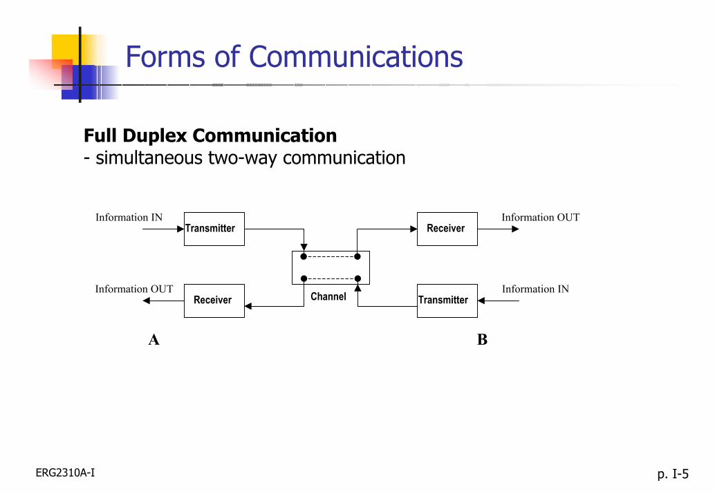
Mathematically, a system is a rule used for assigning a function g(t)(the output) to a function f(t) (the input); that is,
g(t) = h{ f(t) }where h{•} is the rule or we call the impulse function.
h(t)f(t) g(t)
For two systems connected in cascade, the output of the first system forms the input to second, thus forming a new overall system:
g(t) = h2 { h1 [ f(t) ] } = h{ f(t) }
ERG2310A-I p. I-11
Linear System
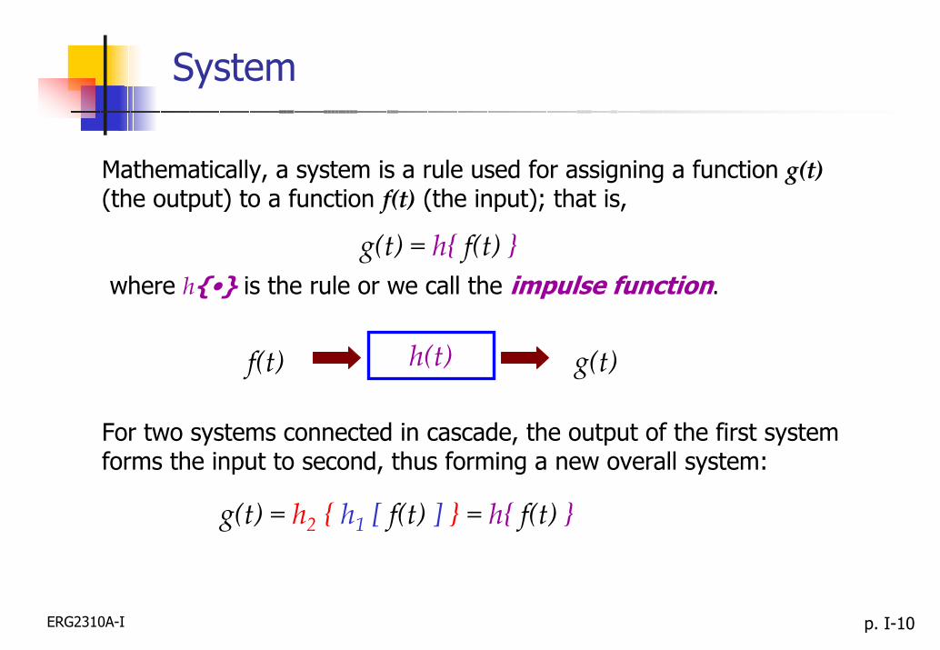
If a system is linear then superposition applies; that is, if
g1(t) = h{ f1(t) }, and g2(t) = h{ f2(t) }then
h{ a1 f1(t) + a2 f2(t) } = a1 g1(t) + a2 g2(t) (*)
where a1, a2 are constants. A system is linear if it satisfiesEq. (*); any system not meeting these requirement is nonlinear.
ERG2310A-I p. I-12
Time-Invariant and Time-Varying
A system is time-invariant if a time shift in the input resultsin a corresponding time shift in the output so that
.any for )}({)( 000 tttfhttg −=−
The output of a time-invariant system depends on time differences and not on absolute values of time.
Any system not meeting this requirement is said to be time-varying.

ERG2310A-I p. I-13
Fourier Series
A periodic function of time s(t) with a fundamental period of T0 can be represented as an infinite sum of sinusoidal waveforms. Such summation, a Fourier series, may be written as:
∑∑∞
=
∞
=
π+
π+=
1 01 00 ,2sin2cos)(
nn
nn T
ntBTntAAts (1)
where the average value of s(t), A0 is given by
∫−= 2
0
20
,)(1
00
T
T dttsT
A (2)
while
∫−
π= 2
0
20
,2cos)(2
00
T
T dtTntts
TAn (3)
and.2sin)(2 2
0
20
00∫−
π=
T
T dtTntts
TBn (4)

ERG2310A-I p. I-14
Fourier Series
An alternative form of representing the Fourier series is
∑∞
=
φ−
π+=
1 00
2cos)(n
nn TntCCts (5)
where (6),00 AC =
,22nnn BAC +=
.tan 1
n
nn A
B−=φ
(7)
(8)
The Fourier series of a periodic function is thus seen to consist of a summation of harmonics of a fundamental frequency f0 = 1/T0.
The coefficients Cn are called spectral amplitudes, which represent the amplitude of the spectral component Cn cos(2πnf0t − φn) at frequency nf0.

ERG2310A-I p. I-15
Fourier Series
The exponential form of the Fourier series is used extensively in communication theory. This form is given by
∑∞
−∞=
π
=n
nTntj
eSts ,)( 02
where
∫−
− π
= 20
20
02
.)(1
0
T
TTntj
dtetsT
Sn
Note that Sn and S−n are complex conjugate of one another, that is
(9)
(10)
(11).*nn SS −=
These are related to the Cn by
.2
njnn eCS φ−= (12),00 CS =

ERG2310A-I p. I-16
Fourier Series
Amplitude Spectra (Line Spectra)Cn
Fig.(a)
Note that except S0 = C0, each spectral line in Fig. (a) at frequency fis replaced by the two spectral lines in Fig. (b), each with half amplitude, one at frequency f and one at frequency - f.
0 fo 2fo 3fo 4fo 5fo 6fo (n-1) fo nfo
|Sn|
-nfo -(n-1)fo ••• - 6fo0-5fo -4fo -3fo -2fo -fo 0 fo 2fo 3fo 4fo 5fo 6fo ••• (n-1) fo nfo
••• •••
Fig.(b)
ERG2310A-I p. I-17
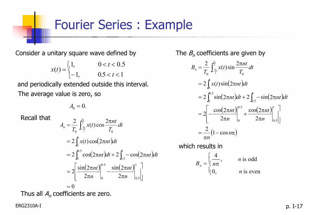
Fourier Series : Example
The Bn coefficients are given byConsider a unitary square wave defined by
( )
( ) ( )
( ) ( )
( )π−π
=
ππ+
ππ−=
π−+π=
π=
π=
∫∫∫
∫−
nn
nnt
nnt
dtntdtnt
dtnttx
dtTnttx
TB
T
Tn
cos12
22cos
22cos2
2sin22sin2
2sin)(2
2sin)(2
1
5.0
5.0
0
1
5.0
5.0
0
1
0
00
20
20
<<−<<
= 150 ,15.00 ,1
)(t.t
tx
and periodically extended outside this interval. The average value is zero, so
.00 =A
Recall that
( )
( ) ( )
( ) ( )
0
22sin
22sin2
2cos22cos2
2cos)(2
2cos)(2
1
5.0
5.0
0
1
5.0
5.0
0
1
0
00
20
20
=
ππ−
ππ=
π−+π=
π=
π=
∫∫∫
∫−
nnt
nnt
dtntdtnt
dtnttx
dtTnttx
TA
T
Tn
Thus all An coefficients are zero.
which results in
π=even is ,0
odd is ,4
n
nnBn

ERG2310A-I p. I-18
Fourier Series : Example
The Fourier series of a square wave of unitary amplitude with odd symmetry is therefore
)10sin516sin
312(sin4)( K+π+π+π
π= ttttx
1st term 1st + 2nd terms 1st + 2nd + 3rd terms
Sum up to the 6th term

ERG2310A-I p. I-19
Fourier Transform
Representation of an Aperiodic Function
)()(lim tftfTT=
∞→
Consider an aperiodic function f(t)
To represent this function as a sum of exponential functions overthe entire interval (-∞, ∞), we construct a new periodic functionfT(t) with period T.
By letting T→∞,
(13)

ERG2310A-I p. I-20
Fourier Transform
The new function fT(t) can be represented by an exponential Fourier series, which is written as
∑∞
−∞=
ω=n
tjnnT eFtf ,)( 0 (14)
where
∫−
ω−=2/
2/0)(1 T
T
tjnTn dtetf
TF (15)
and ./20 Tπ=ω

ERG2310A-I p. I-21
Fourier Transform
For the sake of clear presentation, we set
,0ω=ω∆
nn ,)( nn TFF∆
=ω
Thus, Eq.(14) and (15) become
∑∞
−∞=
ωω=n
tjnT
neFT
tf ,)(1)(
∫−
ω−=ω2/
2/.)()(
T
T
tjTn dtetfF n
The spacing between adjacent lines in the line stream of fT(t)is
./2 Tπ=ω∆
(16)
(17)
(18)
(19)

ERG2310A-I p. I-22
Fourier Transform
Using this relation for T, we get
∑∞
−∞=
ω
πω∆
ω=n
tjnT
neFtf .2
)()(
As T becomes very large, ∆ω becomes smaller and the spectrumbecomes denser.
(20)
In the limit T → ∞, the discrete lines in the spectrum of fT(t) mergeand the frequency spectrum becomes continuous.
Therefore,∑
∞
−∞=
ω
∞→∞→ω∆ω
π=
n
tjnTTT
neFtf )(21lim)(lim (21)
∫∞
∞−
ω ωωπ
= deFtf tj)(21)(becomes (22)

ERG2310A-I p. I-23
Fourier Transform
In a similar way, Eq. (18) becomes
.)()( ∫∞
∞−
ω−=ω dtetfF tj (23)
Eq. (22) and (23) are commonly referred to as the Fourier transform pair.
Fourier Transform
.)()( ∫∞
∞−
ω−=ω dtetfF tj
Inverse Fourier Transform
∫∞
∞−
ω ωωπ
= deFtf tj)(21)(
ERG2310A-I p. I-24
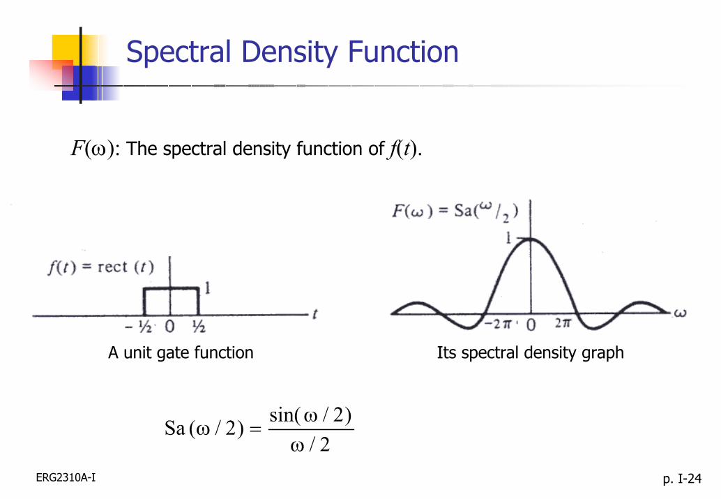
Spectral Density Function
F(ω): The spectral density function of f(t).
Fig. 3.2
A unit gate function Its spectral density graph
2/)2/sin()2/(Sa
ωω
=ω

ERG2310A-I p. I-25
Parseval’s Theorem
The energy delivered to a 1-ohm resistor is
∫∫∞
∞−
∞
∞−== .)()()( *2 dttftfdttfE (24)
Using Eq. (22) in (24), we get
.)()(21
)()(21
)(21)(
*
*
*
∫
∫ ∫
∫ ∫
∞
∞−
∞
∞−
∞
∞−
ω−
∞
∞−
∞
∞−
ω−
ωωωπ
=
ω
ω
π=
ωω
π=
dFF
ddtetfF
dtdeFtfE
tj
tj ∫∞
∞−
ω ωωπ
= deFtf tj)(21)(
(25)
Parseval’s Theorem:
∫∫∞
∞−
∞
∞−ωω
π= .)(
21)( 22 dFdttf (26)

ERG2310A-I p. I-26
Fourier Transform: Impulse Function
The unit impulse function satisfies
(27),1)( =δ∫∞
∞−dxx
≠=∞
=.0 0,0
)(xx
xδ (28)
Using the integral properties of the impulse function, the Fourier transform of a unit impulse, δ(t), is
{ } .1)()( 0 ==δ=δℑ ∫∞
∞−
ω− jtj edtett (29)If the impulse is time-shifted, we have
{ } .)()( 000
tjtj edtetttt ω−∞
∞−
ω− =−δ=−δℑ ∫ (30)

ERG2310A-I p. I-27
Fourier Transform: Complex Exponential Function
The spectral density of will be concentrated at ±ω0.tje 0ω±
{ }
,21
)(21)(
0
001
tj
tj
e
de
ω±
∞
∞−
ω−
π=
ωωωδπ
=ωωδℑ ∫ mm
(31)
Taking the Fourier transform of both sides, we have(32)
{ } { }tje 0
21)( 0
1 ω±− ℑπ
=ωωδℑℑ m
which gives{ } )(2 0
0 ωωπδω m=ℑ ± tje (33)

ERG2310A-I p. I-28
Fourier Transform: Sinusoidal Function
The sinusoidal signals and can be written in terms ofthe complex exponentials.
t0cosω t0sin ω
Their Fourier transforms are given by
{ } { }),()(
cos
00
21
21
000
ω+ωπδ+ω−ωπδ=
+ℑ=ωℑ ω−ω tjtj eet
(34)
{ } { }.)()(
sin
00
21
21
000
j
eet tjj
tjj
ω+ωπδ−ω−ωπδ=
−ℑ=ωℑ ω−ω
(35)
ERG2310A-I p. I-29
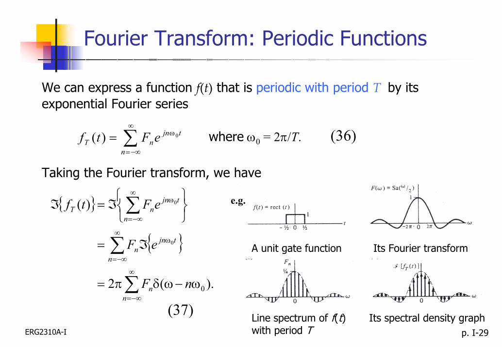
Fourier Transform: Periodic Functions
We can express a function f(t) that is periodic with period T by itsexponential Fourier series
∑∞
−∞=
ω=n
tjnnT eFtf 0)( (36)where ω0 = 2π/T.
Taking the Fourier transform, we have
e.g.
(37)
{ }
{ }
∑
∑
∑
∞
−∞=
∞
−∞=
ω
∞
−∞=
ω
ω−ωδπ=
ℑ=
ℑ=ℑ
nn
n
tjnn
n
tjnnT
nF
eF
eFtf
).(2
)(
0
0
0
A unit gate function Its Fourier transform
Line spectrum of f(t) with period T
Its spectral density graph

ERG2310A-I p. I-30
Time and Spectral Density Functions
ERG2310A-I p. I-31
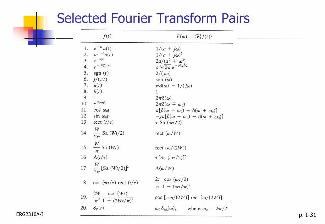
Selected Fourier Transform Pairs

ERG2310A-I p. I-32
Properties of Fourier Transform
Linearity (Superposition)
)()()()( 22112211 ω+ω↔+ FaFatfatfa
Time Shifting (Delay)tjeFttf 0)()( 0
ω−ω↔−
Frequency Shifting (Modulation)Complex Conjugate)()( ** ω−↔ Ftf )()( 0
0 ω−ω↔ω Fetf tj
DualityConvolution
).(2)( ω−π↔ ftF)()()()( 2121 ωω↔∗ FFtftf
Scaling
ω
↔a
Fa
atf 1)( Multiplicationfor .0≠a)()()()( 2121 ω∗ω↔ FFtftf
Differentiation
)()()( ωω↔ Fjtfdtd nn
n

ERG2310A-I p. I-33
Properties of Fourier Transform
).(2)( ω−π↔ ftFDuality
ω
↔a
Fa
atf 1)( .0≠aScaling
for
ERG2310A-I p. I-34
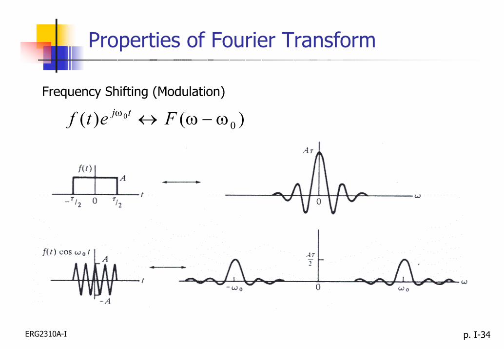
Properties of Fourier Transform
Frequency Shifting (Modulation)
)()( 00 ω−ω↔ω Fetf tj
ERG2310A-I p. I-35
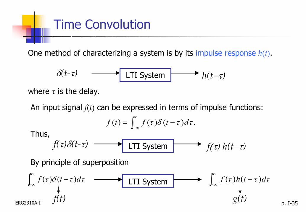
Time Convolution
One method of characterizing a system is by its impulse response h(t).
δ(t-τ) h(t−τ)LTI System
where τ is the delay.
An input signal f(t) can be expressed in terms of impulse functions:
.)()()( ∫∞
∞−−= ττδτ dtftf
Thus,f(τ)δ(t-τ) f(τ) h(t−τ)LTI System
By principle of superposition
∫∞
∞−− ττδτ dtf )()(
f(t)
τττ∫∞
∞−− dthf )()(
g(t)
LTI System

ERG2310A-I p. I-36
Time Convolution
For a linear time-invariant system, if an input f(t) pass through a system with impulse response h(t), the output g(t) will be
τττ∫∞
∞−−= dthftg )()()(
Thus,).()()( thtftg ∗= This result is known as convolution integral.
An important property of the Fourier transform is that it reducesthe convolution integral operation to an algebraic product.
).()()( ωω=ω HFG
Thus convolution in the time domain corresponds to multiplication inthe frequency domain.

ERG2310A-I p. I-37
Properties of Convolution
Commutative Law
)()()()( 1221 tftftftf ∗=∗
Distributive Law
[ ] )()()()()()()( 3121321 tftftftftftftf ∗+∗=+∗
Associative Law
[ ] [ ] )()()()()()( 321321 tftftftftftf ∗∗=∗∗
ERG2310A-I p. I-38
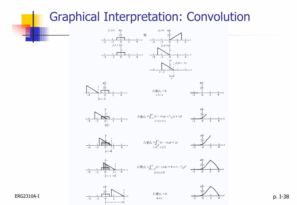
Graphical Interpretation: Convolution


![CAN Lecture - Wayne State Universitywebpages.eng.wayne.edu/.../CAN_Lecture.pdfTitle: Microsoft PowerPoint - CAN_Lecture [Compatibility Mode] Author ` /Â[Zòä¦9 Created Date: 11/16/2009](https://img.pdfslide.net/doc/110x75/5f3e291ba64e076adb6aefb7/can-lecture-wayne-state-title-microsoft-powerpoint-canlecture-compatibility.jpg)