Embed Size (px)
Citation preview

REQUEST FOR PROPOSAL (RFP) ON CRYO TURBO PUMP TEST (CTPT) INSTRUMENTATION SYSTEM
1. INTRODUCTION
Cryo Turbo Pump Test Facility (CTPT) is planned to qualify flight sub systems used in GSLV and GSLV MKIII launch vehicles. This facility meets long duration test requirements of 200Secs for CUSP/C25 Turbo Pump articles and 1200sec for Hydrogen Tank Pressurisation Module (HTPM).
The main scope of Instrumentation is to establish Field Instrumentation, Signal conditioning room (SCR) Instrumentation and Control Room Instrumentation at Cryo Turbo pump Test Facility.
This Request For Proposal (RFP) defines the scope and realization of Cryo Turbo Pump Test Facility Instrumentation Systems.
The scope of work as per RFP document includes Supply of Instrumentation Items and Field Erection Material as per
IPRC specifications. For supply portion, prior approval / despatch clearance shall be obtained from the Department .
Detailed configuration diagram, Signal Flow Diagram, Rack Assembly & Wiring Diagram, Field Termination Diagram, Interface diagram(measurement, Control, Data Acquisition and Auxiliary System) shall be prepared by contractor during detailed engineering and are to be updated in the final documents.
Installation, Erection & Commissioning of field, Signal Conditioning and control room instrumentation (Field element like pressure/temperature transmitter installation, Mounting, cabling, impulse tubing, commissioning, glanding, termination & grounding )
Rack assembly, mounting of equipments electrical wiring & Termination (Instrumentation rack assembly, Mounting of Instrumentation sub systems, Auxiliary systems, wiring and Equipment powering )
Testing and Evaluation Generation of final updated test reports and as built drawing.
2. INSTRUMENTATION SYSTEM REQUIREMENT FOR CTPT
The field elements in the Test stand are remotely controlled and monitored from the Control Centre located 650 meter (approx) away from the test stand. All Driver and signal conditioning Electronics are kept in the Signal conditioning room (SCR) located approximately 75 m away from the test facility. Operator stations, Test Director Consoles, Control system and data Acquisition servers are kept in the Control Room.
The Instrumentation system is categorized into three parts namely Field Instrumentation, Signal conditioning room Instrumentation and Control Room Instrumentation. Details are given in Figure 1.
Page 1 of 117

REQUEST FOR PROPOSAL (RFP) ON CRYO TURBO PUMP TEST (CTPT) INSTRUMENTATION SYSTEM
Figure 1: CTPT Instrumentation System
Instrumentation requirements are given below.
Sl. No Measurement Total(Channels)
Total wired channels(20%)
Facility Measurement1. Absolute Pressure measurement 147 1762. Differential Pressure
measurement(DP and Fluid Level Indicator)
29 35
3. Vacuum Pressure Measurement 13 164. Pressure switch in fluid circuit 13 165. Pressure switch in cubicle 25 306. Temperature fluid measurement 84 1007. Temperature Skin measurement 70 848. Flow measurement 24 309. Speed Measurement 24 3010. Level measurement 72 85
Total 501 602Test Article Measurement
11. Pressure Measurement 96 11512. Temperature Measurement 128 15313. Voltage Measurement 72 8614. Hall Sensor Event 16 19
Total 312 373
Page 2 of 117

REQUEST FOR PROPOSAL (RFP) ON CRYO TURBO PUMP TEST (CTPT) INSTRUMENTATION SYSTEM
High Speed Measurement
15. Vibration Measurement 24 2916. Voltage Measurement 8 10
Total 32 39Command System Requirement
17. EP valve 240 28818. Control valve 40 4819. Engine Valve Command 50 60
20. Pyro valve Command 16 20
Total 346 416
Auxiliary System21. CCTV 12 1522. Intercommunication 40 4823. Large Screen Display 6 824. Large Screen Monitor 14 1725. Time code generator with IRIG-B 3 426. Slave Display 6 827. Access control 4 528. Surveillance Camera 5 6 To
tal90 111
Safety System
29. Hydrogen monitors 16 2030. Oxygen monitors 16 2031. Flame detector 16 2032. Siren 2 233. Traffic signal posts 4 4 Total 54 66 Grand Total 1335 1609
2.1 DEFINITION OF FIELD INSTRUMENTATIONPage 3 of 117

REQUEST FOR PROPOSAL (RFP) ON CRYO TURBO PUMP TEST (CTPT) INSTRUMENTATION SYSTEM
Instrumentation related to the field instruments which are kept in the test stand is covered under field instrumentation. This includes supply & installation of Junction Box, SOV cubicle, impulse / pneumatic tubing, cable tray, structural support and installation of field elements.2.1.1 Measurement system
a) Sensing elements for measuring and monitoring pressure, temperature, flow, level, Speed, vibration etc.
b) Instrumentation cables.c) Instrument impulse lines along with isolation valves, manifolds, and
SS tube fittings.d) Main and branch cable trays/ducts.e) Junction boxes (JB) with terminal blocks.
2.1.2 Command systema) Pneumatic and electrical lines for Electro Pneumatic valves.b) Status switches for EP valves (proximity switches).c) Solenoid valves and solenoid valve cubicles.d) Valve Positioner with integrated position feedback for control
valves.e) Control cables.f) Junction boxes with terminal blocks.g) Main and branch cable trays/ducts.
2.1.3 Auxiliary system & safety Instrumentation a) CCTV System camerab) Inter communication systemc) Hydrogen, Oxygen ,Flame detection systemd) Instrumentation and power Cablese) Junction boxes with terminal blocksf) Main and branch cable trays/ducts
2.2 CONCEPT OF FIELD INSTRUMENTATIONThe process is remotely controlled and measured from the Control
Centre located 650 m (approx) away from the test stand. The signals from the test facility & test article are interfaced with DAS/PLC front end electronics at Signal conditioning room (SCR) located approximately 75 m away from the test facility. Separate explosion proof field junction boxes (JB) shall be used for facility and test article measurements.2.2.1 Facility Measurement Systema) Armoured cables (2 core / 4 core) shall be used for connecting the Field
Junction Box (FJB) to facility field instruments.b) Multi core cable shall be used between FJB to SCR.c) HART protocol based pressure Transmitters are planned for facility
pressure measurements.
Page 4 of 117

REQUEST FOR PROPOSAL (RFP) ON CRYO TURBO PUMP TEST (CTPT) INSTRUMENTATION SYSTEM
d) The length of impulse lines should not exceed 5 meters and shall be without any joint. If it exceeds 5 metre joints shall be weldable and are to be routed as per requirements.
e) Impulse tubing shall be pneumatic tested to 1.1 times the operating pressure.
f) RTD temperature sensors with HART protocol based Temperature Transmitters are planned for facility temperature measurements.
g) Turbine and Vortex flow meters are planned for facility flow measurements.
h) HART protocol based differential pressure transmitters are used for level measurement.
2.2.2 Test Article measurement systema) Test article measurement cabling shall be carried out using Multi core
cables between SCR and test article measurements junction box (FJB). b) Single core shielded low noise co-axial cable shall be used for vibration
and dynamic pressure measurement from SCR to test article junction box (FJB).
c) Cabling from FJB to test article sensor is PTFE 4/6 Core cables.2.2.3 EP valve Command Systema) The EP valve command chain is planned with main & redundant coil
solenoid valve and is operated through independent command chain.b) 5/10 Nos. of solenoid valves shall be mounted in one SOV cubicle.c) A pressure switch shall be provided after the isolation valve at the
pneumatic pressure inlet for all the SOV cubicles.d) The length of command tubing from SOV cubicle to the
EP valve actuator shall be less than 10 meter, so that nearby commands are grouped together.
e) The availability of pneumatic pressure is to be confirmed by installing pressure switch in each cubicle.
f) Command tubing shall be carried out between Solenoid valve and EP valve actuator using 8mm OD SS tube.
g) Single acting type solenoid valve is used for EP valves operating at 8 bar command pressure.
h) 10/20 core Armoured cables shall be used between SOV cubicle and FJB and 40/80 core armoured cables shall be used between FJB to SCR.
i) 4 core armoured cable shall be used between termination box located at EP valve & FJB and 96 core armoured cables shall be used between FJB to SCR for EP valve status.
j) Pneumatic tubing shall be pneumatic tested at 1.1 times the operating pressure.
2.2.4 Control valve command system a) Control valve shall have smart valve Positioner with integrated position
transmitter.b) Pneumatic supply for actuating control valves shall be connected from
the facility command header using 8mm OD SS tubes.Page 5 of 117
REQUEST FOR PROPOSAL (RFP) ON CRYO TURBO PUMP TEST (CTPT) INSTRUMENTATION SYSTEM
c) Pneumatic tubing shall be pneumatic tested at 1.1 times the rated pressure.
d) 4 core shielded armoured cable shall be used between SMART Valve Positioner to FJB. Multicore shielded armoured cable shall be used between FJB to SCR.
2.2.5 Engine/Pyro command systema) Separate FJB shall be planned at Engine/Pyro commands.b) 2 core armoured cables shall be used between FJB to Engine/Pyro c) Multicore armoured shielded cabling shall be carried out between FJB to
SCR.2.2.6 Auxiliary Systema) Suitable mounting structures for mounting CCTV cameras, inter-
communication units and Time Display Units shall be designed and fabricated.
b) The cabling for CCTV cameras, inter-communication units and Time Display Units shall be carried out between field equipments to FJB.
c) Multicore shielded armoured cable shall be used between FJB to SCR.d) Armoured coaxial cable for camera from Test stand to control room.2.2.7 Safety Systema) Suitable mounting structures for mounting Hydrogen Monitors, Oxygen
Monitors and Flame detector shall be designed and fabricated.b) 4 core shielded armoured cable shall be used between safety sensor to
FJB. c) Multicore shielded armoured cable shall be used between FJB to SCR.
2.3 DEFINITION OF SIGNAL CONDITIONING ROOM INSTRUMENTATION
Instrumentation systems which are kept in the Signal conditioning room is covered under SCR instrumentation. This includes Assembly, Integration and Wiring of Control system, Data Acquisition System and Command system Rack Equipments. Supply & installation of Connector plates, Harnessing materials, Cable Management trays and Rack Interface cables.2.3.1 Measurement system
a) Barriers, Hart Management System, Signal conditioners, Data Acquisition Systems for measuring and monitoring pressure, temperature, flow, level, Speed, vibration etc.
b) Instrumentation cables.c) Equipment mounting, Rack wiring and Inter Connection Cable
Preparations with Multi pin Connectors. d) Cable Management Trays, Ferrules with terminal blocks.
2.3.2 Command systema) Valve Driver Relays, PLC Remote I/O, Status Barriers, Isolators, Hall
Sensors and power supplies for EP valve, Control Valve and Page 6 of 117
REQUEST FOR PROPOSAL (RFP) ON CRYO TURBO PUMP TEST (CTPT) INSTRUMENTATION SYSTEM
Engine/Pyro Valve Commands.b) Control cables.c) Equipment mounting, Rack wiring and Inter Connection Cable
Preparations with Multi pin Connectors. d) Cable Management Trays, Ferrules with terminal blocks.
2.3.3 Auxiliary system & safety Instrumentation a) CCTV Systemb) Timing Systemc) Inter communication systemd) Hydrogen, Oxygen ,Flame detection system Barrierse) Instrumentation and power Cablesf) Equipment mounting, Rack wiring and Inter Connection Cable
Preparations with Multi pin Connectors. g) Cable Management Trays, Ferrules with terminal blocks
2.4 CONCEPT OF SIGNAL CONDITIONING ROOM INSTRUMENTATIONField elements are interfaced through Signal conditioning room
Equipments. All Instrumentation systems Front Ends are housed in the 48 Nos of Instrumentation Racks. Signal conditioning room (SCR) located approximately 650 m away from the Control Room and 75 m away for Test Stand. Separate Instrument Racks are planned for Measurement, command and Auxiliary systems. Functional check of all 48 Nos of racks are to be carried out by feeding electrical signal and results are to be logged.
2.4.1 Facility Measurement Systema) Multi core cable shall be used between FJB to SCR and are terminated
in the Measurement Rack.d) Isolated barriers with dual analog output is used. Outputs are
interfaced to Analog DAS through separate 64/96 core PTFE interface cables
b) HART Management systems are planned for smart pressure/temperature facility measurements.
2.4.2 Test Article measurement systema) Test article measurement cabling shall be carried out using Multi core
cables between FJB and SCR. All cables are Terminated in the Test Article measurement Rack with multi pin connectors..
b) Data Acquisition system with builtin digitizer is planned for test article measurements.
c) All signal from/to is routed through Barriers and internal rack wiring is with PTFE cables.
d) Signal conditioner outputs are interfaced to PLC analog input card through separate 64/96 core PTFE interface cables.
2.4.3 EP valve Command Systema) EP valves are actuated through Valve Driver Rack.
Page 7 of 117
REQUEST FOR PROPOSAL (RFP) ON CRYO TURBO PUMP TEST (CTPT) INSTRUMENTATION SYSTEM
b) The EP valve status are isolated with status barriers.c) Command acknowledgement and status are acquired through Digital
DAS and are interfaced through separate 64/96 core PTFE interface cables.
d) A pressure switch shall be provided after the isolation valve at the pneumatic pressure inlet handled with DDAS.
e) Armoured 96 core cables used between FJB to SCR for EP valve status and 64 core for command are terminated through multi pin connectors.
f) PLC system for auto/abort and manual command operations.2.4.4 Control valve command system
a) Control valve shall have smart valve Positioner with integrated position transmitter are inter faced with safety barriers.
b) Multicore shielded armoured cable used between FJB to SCR are terminated with multipin connectors.
c) Feedback outputs are interfaced to Analog DAS through separate 64/96 core PTFE interface cables.
2.4.5 Engine/Pyro command systema) Remote controlled power supplies with contactors are mounted.b) All commands are routed through Separate Hall sensors for current
monitoring. Pyro commands are routed through SARU unit.c) Field and interface cables are terminated through multipin
connectors.2.4.6 Auxiliary System
a) Video switcher, Amplifiers, Fibre optic converters and Network switches are mounted in the Auxiliary system Rack.
b) The cabling for CCTV cameras, inter-communication units and Time Display Units shall be carried out with Fibre/Copper connectors.
c) Multicore Single mode Fibre cable is planned between SCR and control room.
2.4.7 Safety Systema) Safety barriers and power supplies are mounted in the rack.b) Conditioned signals are provided to DAS through Interfaces cables.
2.5 DEFINITION OF CONTROL ROOM INSTRUMENTATIONInstrumentation systems which are kept in the Control Room is
covered under Control Room instrumentation. This includes Assembly, Integration and Wiring of Control system, Data Acquisition System servers, Operator Mimic nodes, Expert Display nodes, Test Director consoles and Auxiliary system Rack Equipments. Supply & installation of Connector plates, Harnessing materials, Cable Management trays, Control switches, Indicators and Rack Interface cables. Mounting of Large screen Displays, Video Displays, Slave clocks and surveillance cameras.
2.5.1 Data Acquisition systemPage 8 of 117

REQUEST FOR PROPOSAL (RFP) ON CRYO TURBO PUMP TEST (CTPT) INSTRUMENTATION SYSTEM
a) Mounting of Display nodes, Processing and Remote control nodes.b) Assembly and Integration of Servers and Data storage systems.c) Inter connecting all nodes with Fibre/CAT-6 Cables.d) Cable Management Trays, Ferrules with terminal blocks
2.5.2 Command systema) Mounting of Mimic Operator nodes, Console switches, Indicators,
Console wiring.b) Assembly and Integration of PLC CPU modules, Servers.c) Cable Management Trays, Ferrules with terminal blocks
2.5.3 Auxiliary system & safety Instrumentation a) CCTV Systemb) Timing Systemc) Inter communication systemd) Hydrogen, Oxygen , Flame detection Display nodes.e) Coaxial, Fibre optic Cables and UTP CAT-6 Cables.f) Equipment mounting, Rack wiring and Inter Connection Cable
Preparations with Multi pin Connectors. g) Cable Management Trays, Ferrules with terminal blocks
2.6 CONCEPT OF CONTROL ROOM INSTRUMENTATION Control Room Instrumentation system accepts SCR system data
and are distributed to all consoles for control and monitoring. Communication between SCR and control room is established through Fibre link. Signal conditioning room (SCR) located approximately 650 m away from the Control Room. Functional checking of Instrumentation system up to display are to be carried out for clearance.
2.6.1 Data Acquisition Systema) All Data acquisition systems housed in the SCR are remotely
controlled. b) DAS data are processed and provided to display nodes through
network.c) Servers and network switches are mounted in the Racks. All expert
display nodes are mounted in the consoles. d) Communication between the systems are realized through CAT-6
Network cables.e) All data are displayed through Numeric Display node and On-Line
Trend Graph node.
2.6.2 Control Systema) All Remote PLC I/O are mounted in SCR and are communicated to
Control room PLC through Fibre link.b) All application programs are loaded in the PLC.c) Command to the Field elements are provided from the Mimic
operator node.d) Auto commands are generated from PLC through sequence
programs.Page 9 of 117
REQUEST FOR PROPOSAL (RFP) ON CRYO TURBO PUMP TEST (CTPT) INSTRUMENTATION SYSTEM
e) In case of abnormality control system executes abort sequence for safeguarding facility and Test article systems.
f) Communication between control room and SCR is established through Fiber Link.
2.6.3 Auxiliary Systema) Important Facility and Test article Views are displayed in the Large
screen displays and monitors.b) Each console is provided with intercom and video display.c) Video Display with Time insertion is provided.d) Slave display for Countdown clock and UTM Time.e) Network switch traffics are continuously monitored.f) Siren prior to major trails with traffic light.g) Physically separate network for Video, DAS and Control system.
3. SCOPE OF RFP
All Instrumentation installation, supply of commissioning materi-als, Rack wiring, Connector/Terminal block termination and cabling is the responsibility of the Vendor. Scope of work for instrumentation sys-tem is defined through chain diagrams given in Annexure I.
Scope of this RFP includes mainly detailed engineering, supply of items, assembly & inspection and erection & commissioning of field in-strumentation, Signal conditioning room and Control Room Instrumen-tation for Cryo Turbo Pump Test Facility. Detailed scope of above activ-ities is given below.
3.1 Detail EngineeringInput documents to be referred for preparing detail engineering are: P & I diagrams Measurement Plan Codes & Standards specified in RFP Instrument specification sheet The following documents shall be prepared and submitted by the
vendor for the approval from the Department during detailed engineering: Instrument/equipment Layout diagram Instrument/equipment erection diagram Instrument/equipment mounting procedure Cable and Cable tray routing diagram for instrumentation/ power
cable Pneumatic/Impulse tube routing diagram Field Instrument, Junction Box, SCR cable and Control Room
Termination diagrams Equipment Layout and Rack Wiring Diagram
Consol switch and Indicator Wiring Diagram Display node position and Cable routing Diagram Auxiliary system mounting Layout
Page 10 of 117

REQUEST FOR PROPOSAL (RFP) ON CRYO TURBO PUMP TEST (CTPT) INSTRUMENTATION SYSTEM
Supply of items as per requirement given in the price format for establishment of CTPT field instrumentation.
Testing plan. Quality assurance plan
a) Field equipment shall be properly grouped at a convenient location based on the equipment layout diagrams.
b) Independent junction boxes shall be used for command, measurement, auxiliary and safety systems.
c) Separate trays shall be used for routing pneumatic tubes and cables.d) Field instruments shall be mounted on 2” pipe stands. The
instrument stands shall have a suitable height so that instrument shall be mounted at 1.4m from ground or platform. If the instrument to be mounted on a platform the preferred location shall be on the outside the hand railing.
e) Field instruments, which are exposed to open terrain, shall be provided with weather canopy.
f) More than one connection per terminal is not allowed.g) To protect RTD probes and flow meter pickup coils, from mechanical
damage/entry of water, suitable individual enclosures shall be designed.
h) All Equipments in the Racks are mounted with space to have proper ventilation.
i) All rack wiring are provided with proper labels to have easy fault fixing.
j) Mechanical assembly and position of Instruments and accessories is to be provided
k) Proper internal wiring, routing and Harnessingl) Electrical and functional testing of wired racks.m) Earthing of all racks and instruments.
3.1.1. Detail Engineering of measurement systemSeparate field junction boxes shall be used for facility and test
article measurements.3.1.1.1 Test Article Measurements:
a) Separate junction box shall be planned for each type of measurement (Pressure, temperature, vibration, and speed etc.)
b) Cabling from test article sensors to FJB is PTFE 6 Core for pressure and 4 core for RTD/Flow/Speed.
c) Multi core 96/64 shielded PVC armoured cabling shall be carried out between test article pressure, temperature (RTD), displacement and speed measurement junction boxes (FJB) to SCR.
d) Multicore thermocouple cabling shall be carried out between thermocouple JB to SCR for high temperature and heat flux measurement.
e) Single core shielded co-axial cable shall be used for vibration, acoustic and dynamic pressure measurement from test article FJB to SCR.
f) Mechanical assembly and position of Instruments and accessories in the Instrument Rack
Page 11 of 117

REQUEST FOR PROPOSAL (RFP) ON CRYO TURBO PUMP TEST (CTPT) INSTRUMENTATION SYSTEM
g) Proper internal wiring, routing and Harnessing of SCR and Control room Racks.
3.1.1.2 Test Facility Measurements:a) All Measurement cables shall be grouped to FJB and are routed to
SCR.b) Field junction boxes with 225 terminals are planned. c) Multi core 64/96 shielded PVC armoured cable shall be used between
FJB to SCR.d) Two core shielded PVC armoured cable shall be used between facility
transmitters (Pressure & Temperature) and FJB.e) Impulse lines for pressure transmitters shall be of 12 mm OD SS tube
and thickness suitable for the process pressure.f) Suitable double compression SS tube fittings shall be used to connect
process line, impulse tubes and instruments.g) The length of impulse lines shall not exceed 5 meters without any
joint wherever not possible lines should be extended through weld or compression fitting connectors.
h) Removal of Absolute/Differential pressure transmitters must be possible without stopping the process. Necessary manifold valves on the process line shall be provided.
i) Four core PVC shielded armoured cabling shall be used between RTD sensor and temperature transmitter.
j) Four core PVC shielded armoured cable shall be used between Turbine flow meter to FJB.
k) Single core shielded cabling shall be carried out between level arrays in run tanks to signal conditioner positioned in Junction box.
l) Four core armoured PVC cabling shall be carried out between pressure/level switch to FJB.
m) Mechanical assembly and position of Instruments and accessories in the Instrument Rack
n) Proper internal wiring, routing and Harnessing of SCR and Control room Racks.
3.1.2. Detail Engineering of command system3.1.2.1 EP Valve
a) The location and quantity of SOV cubicles shall be finalized based on the following criteria: 5/10 Nos. of single acting solenoid valves shall be mounted in one
SOV cubicle The length of command tubing from SOV cubicle to the
EP valve actuator shall be less than 10 meter.b) Two nos of 10/20 core 18AWG shielded armoured cable (one to main
and other to redundant FJB) shall be used between SOV cubicle to FJB for main & redundant command.
c) Separate 64 core shielded armoured 18AWG cable shall be used between main & redundant FJB to SCR.
d) One number of 8 mm OD SS tubing shall be laid between SOV cubicle Page 12 of 117

REQUEST FOR PROPOSAL (RFP) ON CRYO TURBO PUMP TEST (CTPT) INSTRUMENTATION SYSTEM
and single acting EP valve actuator. Suitable double compression SS tube fittings shall be used.
e) Each EP valve shall have an associated explosion proof termination box for the termination of status output.
f) 4 core shielded armoured cable shall be used between termination box located on the EP valve to FJB. 96/64 Multi core PVC shielded armoured cables shall be used between FJB to SCR for status of EP valves.
g) Mechanical assembly and position of Instruments and accessories in the Instrument Rack
h) Proper internal wiring, routing and Harnessing of SCR and Control room Racks.
3.1.2.2 Control Valvea) Pneumatic supply for actuating control valves shall be connected
from the facility command header (8 bar) using 12 mm OD SS tubes.b) Four core shielded armoured cable shall be used between SMART
valve Positioner and FJB for command and position feedback. 64/96 core PVC shielded armoured cables shall be used between FJB to SCR.
c) Suitable canopy shall be provided for the smart valve Positioner available in the control valve.
3.1.2.3 Engine/Pyro Valve ON/OFF commands2 core cabling shall be carried out between valve and FJB for ON/OFF
commands Multicore cabling shall be carried out between FJB and SCR.
3.1.3. Detail Engineering of Auxiliary/Safety systema) Separate field junction boxes shall be used for Auxiliary & safety
systems.b) Separate multi core PVC shielded cables shall be used between SCR
and field junction boxes for inter communication & safety system. 10 core PVC shielded armoured cable shall be used between each field mounted inter communication unit to Auxiliary system junction box.
c) 2 core PVC shielded armoured cabling shall be carried out between external speaker and the field communication system.
d) 4 core PVC shielded armoured cable shall be used to connect the Oxygen, Hydrogen monitors and Flame detectors to the safety junction box.
e) CAT 6 cable has to be laid from CCTV camera post to FJB and SCR.f) Laying of armoured power cable from 230 V outlets available in the
test stand to CCTV camera post & Intercommunication equipment.
3.2. FIELD ELEMENTSMajor Field elements required for installing CTPT instruments are provided to the instrumentation vendor by the department. However
Page 13 of 117

REQUEST FOR PROPOSAL (RFP) ON CRYO TURBO PUMP TEST (CTPT) INSTRUMENTATION SYSTEM
the commissioning materials required are vendor’s scope. The detailed lists are given below:
3.2.1. Free issue materials
The list of field instruments & materials which are free issued by department are given below: HART Protocol based SMART Absolute / Differential Pressure
transmitters with 2 way valve / 5 way valve manifolds. HART Protocol based SMART Temperature transmitters. RTD probes. Turbine flow meter and Vortex flow meter. PVC & Teflon data cables Isolated Barriers Linear 24 V / 20 A power supplies CCTV cameras and Pan/Tilt drive. Inter communication equipments. Hydrogen, Oxygen and Flame detector sensors.
3.2.2. Supply of items
Field instruments & materials which are required to complete the field instrumentation detailed in this RFP shall be supplied by the vendor. The following are the list of items to be supplied by the vendor. The specification of these instruments & materials are given in Annexure V. However any changes or modifications proposed by vendor /department during process design review or detailed engineering review, the vendor shall execute the work as per 4.6.1. Exact quantity and the list of items required for commissioning the facility is provided in the supply of materials list. Low pressure and high pressure dual coil solenoid valve Solenoid valve cubicle with accessories Header for Pneumatic supply inside the SOV cubicle. Pressure switch and isolation valve for SOV cubicle. SS Tubes (8mm / 12mm OD) for pneumatic and impulse tubing. Compression fittings (union, Tee, male & Female adapters,
conversion adapters for one size to another size suitable for 8mm OD SS tubes)
Junction Box (Different sizes) required for connecting measurement, command and Auxiliary systems.
Multi pin connectors DIN rail mountable SMPS 24 V / 20 A (Redundant configuration
with standard diode oring module)
Structural materials like GI Pipe, Different sizes of Mild steel L angles, MS channels and other materials required for providing structural support for instrumentation related items like impulse
Page 14 of 117
REQUEST FOR PROPOSAL (RFP) ON CRYO TURBO PUMP TEST (CTPT) INSTRUMENTATION SYSTEM
tubing, tube fittings and manual valves, cable tray & tray supports, all types of consumables, Kel-f / aluminium washers for leak tightness and accessories for mounting all instruments & instrument supports.
Cable trays (50mm to 300mm width perforated cable trays and 500 mm Ladder type cable trays)
Necessary concrete required for grouting instrument installation pipe, FJB, SOV cubicle and Auxiliary equipments shall be carried out by the vendor.
Aluminium cable glands suitable for different cable diameters Armoured Power / Co-axial / Cat6 Cables for Auxiliary system. Anodized Aluminium Cable Tags with cable number engraved or
punched on the top. End Terminals & Identification ferrules Cable harnessing materials (cable tie, lacing thread, shrinkable
sleeves, name ferrules and terminal mounts) Mounting accessories (clamp, nuts and bolts) Level Sensors with electronics.
a) Canopy for all the field instruments, FJBs and SOV located outdoor.b) Cable duct for rooting the cables inside the racks (50/75/100mm ).c) DIN rail for mounting power supply, electro magnetic relay and
barriersd) All materials furnished shall be new and unused and free of defects.e) These items are to be procured from the identified list of sub
vendors enclosed in Annexure III
3.3. TOOLS FOR ERECTION & COMMISSIONINGThe vendor shall bring necessary tools required for erection &
commissioning of the instruments & components and an instrument work shop shall be made ready at the erection site.
3.4. ERECTION AND COMMISSIONING
3.4.1. General Instructionsa) Erection & commissioning works shall be carried out strictly according
to the specifications stipulated in the RFP, documents/drawings approved by department during detail engineering. Also it shall be carried out as per the supervision of the department’s representative.
b) The Vendor shall provide and maintain a formal system for documenting technical clarification from the Department.
c) Only correctly signed documents which are marked “Approved for Construction” (AFC) shall be used for installation work.
d) Only the best trade practices and correct tools shall be used and all works are expected to be completed in a neat and safe manner.
Welding shall be done only by qualified personnel. Electrical installation shall only be performed by appropriate
Page 15 of 117

REQUEST FOR PROPOSAL (RFP) ON CRYO TURBO PUMP TEST (CTPT) INSTRUMENTATION SYSTEM
qualified trade persons.e) Holes shall be drilled or punched and not burnt out by gas torches or
electric arcs.f) Piping and tubing shall be carried out with the appropriate pipe or tube
bending equipment. g) Instrument/equipment shall be mounted using suitable
stands/brackets/clamps. As far as possible all instruments shall be mounted on instrument support stands. These shall be installed on floors, RCC columns and walls using approved make anchor fasteners/Hilti bolts and on steel structure by drilling suitable holes and using chromium plated/galvanized bolts and nuts or in exceptional cases by welding. After welding, the slag on weld surface shall be removed and one coat of Red-oxide primer and two coat of paint shall be applied over the surface.
h) Equipment shall be installed in a neat, workman like manner so that it is level, plumb, square and properly aligned and oriented.
i) Field Instruments should not be supported from impulse lines, hand rails and vibrating structures.
j) Instruments shall be located such that it is easy to approach for operation and maintenance. Cover can be removed without obstruction and there should not be any problem in re-glanding the cable later on.
k) All indicating instruments shall be located such that its scale is conveniently visible to field operator.
l) Canopy shall be provided for all the instruments, JBs and SOV cubicles located outdoor.
m) All threaded opening of the instruments shall be protected by suitable Aluminium / Chromium plated plugs.
n) Cable insulation resistance shall be checked before laying the cable. If insulation resistance is not within the limits, those cables shall not be used.
o) During installation of the signal and control cables and prior to connection up to the instruments, the cables shall be checked for the insulation resistance, continuity and tagging.
p) The signal and control cables shall be connected to respective terminals, as per the wiring drawings.
3.4.2. Handling & storage of Instrumentsa) The Vendor shall be responsible for the collection of “free-issue”
instrument items, transportation, storage and safe custody of the equipments until completion of its installation and acceptance by Department’s representative. Vendor shall maintain a stock control system to enable material tracking throughout the installation & commissioning of the facility.
b) All instruments shall be visually examined by the Vendor on receipt to ensure that they have not been damaged in transit. Instruments shall then be replaced in their original packing and housed in a separate
Page 16 of 117

REQUEST FOR PROPOSAL (RFP) ON CRYO TURBO PUMP TEST (CTPT) INSTRUMENTATION SYSTEM
secure, dry, cool storage area provided by the department.c) If any item is damaged by the vendor, new item may be procured and
replaced by the vendor with their own cost or the cost of the item will be deducted from the vendor’s bill.
d) When unpacking is necessary, care shall be taken to ensure that accessories are not mislaid or mixed.
e) Instruments shall not be left lying around the construction area.f) All covers and plugs on the instrument connections shall be left in
place until connections are used.
3.4.3. Installation Preparationa) Instrument process connections shall be identified before installation.b) Sensitive electronic instruments/components shall be protected during
welding, drilling & filing activities.c) Metal Filing and metal shaving shall be prevented from falling on the
components/ports/connectors.d) Instrument stands and mounting brackets shall be fabricated according
to design drawings approved by the department.e) Identification tags shall be attached to each field component bearing
its Tag name in accordance with P&ID drawings/ Instrument schedules. f) Identification Tags shall be painted to all Transmitter mounting Pipes.g) Identification Tags shall be painted to all junction boxes and SOV
Cubicle. h) Painting shall be done with white background and black lettering. i) Mechanical assembly and position of Instruments and accessories in
the Instrument Rackj) Proper internal wiring, routing and Harnessing of SCR and Control
room Racks.
3.4.4. Installation
3.4.4.1. Test Article Measurement:a) Multicore 96/64 PVC & Co-axial cabling shall be carried out between
FJB to SCR for test article measurements.b) The co-axial cables shall be laid from FJB to SCR and terminated in
BNC connector. Suitable isolation mounting arrangements shall be provided in the junction boxes for mounting BNC connectors.
c) Thermocouple extension cable shall be laid between FJB and SCR and cable laying shall be carried out as per 3.4.4.15
d) Cable trays shall be laid between Test article JB to SCR. Cable tray laying shall be carried out as per 3.4.4.14
e) All cables are to be Terminated both end with Terminal Block/Multipin Connectors
f) Rack integration and wiring at Signal conditioning roomg) Display node, server mounting and network/power cabling.
3.4.4.2. Facility Pressure a) Absolute and differential pressure transmitters shall be installed in
the transmitter mounting post as per drawing approved by Page 17 of 117

REQUEST FOR PROPOSAL (RFP) ON CRYO TURBO PUMP TEST (CTPT) INSTRUMENTATION SYSTEM
Department.b) A two valve manifold for absolute pressure measurement and five
valve manifold with block equalizing and drain valves for differential pressure measurement shall be installed with the transmitter.
c) Impulse tubing shall be carried out between pressure transmitter and process line by using 12 mm OD SS tube as per 3.4.4.3.
d) Cabling for the transmitters shall be carried out by using 2 core PVC armoured cable between pressure transmitter and FJB. Cabling between FJB to SCR shall be carried out using multi core PVC cable and laying shall be carried out as per 3.4.4.15
e) Cable trays shall be laid between pressure transmitters to Junction box & Junction Box to SCR through cable trench. The layout diagram for the cable trench is provided in the equipment layout drawing. Cable tray laying shall be carried out as per 3.4.4.14.
f) Cables shall be terminated to the instrument /FJB with cable gland.g) Functional verification (insitu) upto online display and Test &
Evaluation.
3.4.4.3. Impulse Tubinga) 12 mm OD S.S. tubes shall be used as impulse tubes. Thickness
shall be selected based on the operating pressure. Instrument tubing shall be laid as per standard on cable trays. The width of cable trays shall be selected as per number of instrument tubing laid.
b) The tube routing shall be carried out as per approved drawing. c) Transmitters shall be mounted above the process pipe line and
continuous slope shall be provided in the impulse line between transmitter and process line.
d) S.S. Tubes shall be cleaned with lint free cloth dipped in acetone and pulled through the tube using nylon wire until all dirt/dust is removed. As a check for thorough cleaning of tubes, last lint free cloth shall be as clean as new. This is to be done in presence of the department’s representative. Outside surface of tube shall also be cleaned by rubbing manually with lint free cloth soaked in acetone. Tubes shall be cleaned by blowing dust free GN2 before laying.
e) Tube bends shall be made with approved and appropriate sizes of tube benders. Bends shall be of uniform curvature and smooth and shall be free from wrinkles, flattening and kinks. Use of filler material during bending is prohibited. Hot bending is also not permitted.
f) Tubes shall be clamped at intervals not exceeding 1 meter with the help of special spacer and clamps.
g) Impulse lines and their supports should be kept away and free from vibrating structures or equipment. Minimum bending radius should be taken as 2.5 times the tube OD.
h) To avoid corrosion of SS Tubes, contacts of SS Tubes with CS/MS surfaces should be avoided by installing brass shims/foil in between SS Tubes and CS/MS Surface.
i) Wherever impulse lines run side by side, they should be neatly bunched together with bolted straps and screwed clamps. Tubing should be ganged vertically rather than horizontally to avoid
Page 18 of 117

REQUEST FOR PROPOSAL (RFP) ON CRYO TURBO PUMP TEST (CTPT) INSTRUMENTATION SYSTEM
collection of dust, dirt and other corrosive conditions.j) S.S. Tubes are terminated by using approved make of double
compression ferrule type fittings and are in general called here as Swagelok fittings.
k) Swagelok fittings shall be installed by qualified fitters who have to undergo qualification test to be conducted by the Quality Surveillance Engineer of the department.
l) Tubes shall be identified at both ends by line number/instrument number/equipment number to which it is terminated by Anodized Aluminium tags of rectangular shape and shall be tied to the tube securely by 16 gauge S. S. wire.
m) Kel-f / aluminium washers (Leak tightness) and consumables required for commissioning activities are party scope.
3.4.4.4. Facility Temperaturea) RTD shall be mounted in the process lines with Kel-f / aluminium
washers as per mounting drawing approved by the Department for non SI lines. In SI lines preparation / soldering of mating feed through connector is vendor’s scope.
b) Temperature transmitters shall be installed in the transmitter mounting post for each RTD sensor as per drawing approved by the Department.
c) Cabling between RTD and temperature transmitters shall be carried out by using 4 core armoured PVC cable. Cabling between temperature transmitter and FJB shall be carried out by using 2 core PVC armoured cable. Cabling between FJB to SCR shall be carried out using multi core PVC cable and laying shall be carried out as per 3.4.4.15
d) Sensor end cables are wired with multi pin connectors.e) Cable trays shall be laid between temperature probes to transmitter,
temperature transmitters to field Junction box & marshalling Junction Box Cable tray laying shall be carried out as per 3.4.4.14
f) Suitable hood shall be provided to protect the RTD sensor.g) Cables shall be terminated to the instrument, JB, RTD sensor using
suitable Aluminium cable gland.h) Functional verification (Decade resistance box) upto online display
and Test & Evaluation.
3.4.4.5. FlowFlow meters are part of process systems and are Installed by the department. The necessary flow subsystems like pre-amplifier / flow transmitter and connectorisation shall be installed as per applicable instrument mounting procedures supplied by the Department. Standard installation drawings approved by department shall be provided.
3.4.4.5.1 Turbine Flow metera) Turbine flow meter pre amplifier are suitably mounted near flow
meter with structure.Page 19 of 117
REQUEST FOR PROPOSAL (RFP) ON CRYO TURBO PUMP TEST (CTPT) INSTRUMENTATION SYSTEM
b) Cable trays shall be laid between flow meter to field Junction box & marshalling Junction Box. The layout diagram for the cable trench is provided in the equipment layout drawing. Cable tray laying shall be carried out as per 3.4.4.14
c) Cabling between Turbine flow meter and FJB shall be carried out by using 4 core armoured PVC cable. Cabling between FJB to SCR shall be carried out using multi core PVC cable and laying shall be carried out as per 3.4.4.15
d) Flow meter cables are soldered with multi-pin connectorse) Functional verification (Function generator) upto online display and
Test & Evaluation.3.4.4.5.2 Vortex Flow meter
a) Flow transmitters shall be installed as per drawing approved by the Department.
b) Installations orientation details given in the design drawing shall be strictly followed.
c) Cabling between vortex flow meter and FJB shall be carried out by using 2 core armored PVC cable. Cable laying shall be carried out as per 3.4.4.15
d) Cable trays shall be laid between vortex flow meter to field Junction box & Marshaling Junction Box to SCR through cable trench. The layout diagram for the cable trench is provided in the equipment layout drawing. Cable tray laying shall be carried out as per 3.4.4.14
e) Cables shall be terminated to the instrument /JB using suitable Aluminium cable gland.
f) Functional verification (Function generator) upto online display and Test & Evaluation.
3.4.4.6. SOV Cubiclesa) 5/10 Solenoid valves shall be mounted inside SOV cubicles.b) SOV cubicle shall be used with single acting type solenoidsc) Single acting type solenoid valve shall used for EP valves operating
at 8 bar command pressure.d) SS Pneumatic header of size minimum 1.25” diameter (for feeding
to all solenoid valves in a SOV cubicle) shall be mounted inside the SOV cubicle.
e) Command tubing shall be carried out between Solenoid valve and EP valve actuator using 8mm OD SS tube. Pneumatic tubing shall be carried out as per 4.4.4.10.
f) Isolation valve and pressure switch shall be mounted at the inlet of pneumatic header available at SOV.
g) SS piping shall be carried out between common command headers available in facility to each SOV header using ½” pipe.
h) Cabling for SOV cubicle shall be carried out by using 2 numbers of 20 core 18AWG shielded armoured cables for main and redundant
Page 20 of 117

REQUEST FOR PROPOSAL (RFP) ON CRYO TURBO PUMP TEST (CTPT) INSTRUMENTATION SYSTEM
coil from SOV cubicle to FJB and multicore cabling shall be carried out between FJB to SCR. Cabling shall be carried out as per 3.4.4.15.
i) The cables shall be terminated at SOV cubicle JB using 2 nos. of Alu-minium cable gland for main and redundant commands.
3.4.4.7. EP Valve Statusa) Cabling for the EP valve status Proximity switches shall be carried
out by using 4 core PVC armoured cable between termination box at EP valve and FJB common for many EP valve status. Cabling between FJB to SCR shall be carried out using multi core PVC cable and laying shall be carried out as per 3.4.4.15
b) Cable trays shall be laid between JB at EP valve to field Junction box & marshalling Junction Box to SCR through cable trench as per drawing approved by department. Cable tray laying shall be carried out as per 3.4.4.14
c) All field status are Terminated in the Junction Boxd) Functional verification by commanding the EP valves and verifying
status upto online display and Test & Evaluation.
3.4.4.8. Smart Valve Positioner for Control Valvea) Smart valve Positioners are used for control valves. Air supply to
Smart valve Positioner shall be supplied from common header using 8 mm / 12 mm OD SS tube. Pneumatic tubing shall be carried out as per 3.4.4.10.
b) Cabling between Smart valve Positioner to FJB shall be carried out by 4 core armoured PVC cable. Multi core cable shall be used for command and status from FJB to SCR. Cable laying shall be carried out as per 3.4.4.15
c) Cable trays shall be laid between Smart valve Positioner to field Junction box & marshalling Junction Box to SCR through cable trench. The layout diagram for the cable trench is provided in the equipment layout drawing. Cable tray laying shall be carried out as per 3.4.4.14
d) Cables shall be terminated to the instrument, FJB using suitable Aluminium cable gland.
3.4.4.9. Pneumatic Tubinga) The scope of work covers installation, routing as per approved
drawing, clamping, supporting and connection of 8mm OD SS tube with fittings.
b) S.S. Tubes shall be cleaned with lint free cloth dipped in acetone and pulled through the tube using nylon wire until all dirt/dust is removed. As a check for thorough cleaning of tubes, last lint free cloth shall be as clean as new. This is to be done in presence of the department’s representative. Outside surface of tube shall also be cleaned by rubbing manually with lint free cloth soaked in acetone. Tubes shall also be cleaned by blowing dust free GN2 before laying.
Page 21 of 117

REQUEST FOR PROPOSAL (RFP) ON CRYO TURBO PUMP TEST (CTPT) INSTRUMENTATION SYSTEM
c) Tube bends shall be made with approved and appropriate sizes of tube benders. Bends shall be of uniform curvature and smooth and shall be free from wrinkles, flattening and kinks. Use of filler material during bending is prohibited. Hot bending is also not permitted.
d) S.S. Tubes are terminated by using approved make of double compression type ferrule fittings and are in general called here as Swagelok fittings. At the place of termination/joint, tubes shall be cut square and burrs if any shall be removed by fine emery paper without reducing wall thickness of the tube. Tube shall be cut with approved brand of tube cutter only.
e) Swagelok fittings shall be installed by qualified fitters who have to undergo qualification test to be conducted by the Quality Surveillance Engineer of the department.
f) Tubing shall be routed on the cable trays and shall be clamped at the intervals not exceeding 1 m. The tubing shall be run in such a manner to provide maximum protection against physical damage. Tubing runs shall be neatly dressed and grouped together where ever possible. Tubes should be ganged vertically rather than horizontally to avoid collection of dirt, dust and other corrosive material.
g) Tubes which are to be terminated on the instruments, may be subjected to vibrations during operation, a semi circular loop shall be formed on the tube near the termination point to avoid damage to the tubes during operation. All such instruments shall be identified in consultation with the department Engineer, before termination of the tubes.
h) Tubes shall be identified at both ends by line number/instrument number/equipment number to which it is terminated by Anodized Aluminium tags of rectangular shape and shall be tied to the tube securely by 16 gauge S. S. wire.
i) Compression unions shall be used for joining the tubes. At the joint an offset of around six inches (3 inches on each side of the joint) shall be given on the tube run, so that the fitting will be away from the surface of the tube support having free access for tightening and checking of leaks during test. Joints on adjacent tubes in a bundle shall be staggered suitably to avoid interference.
j) All the air supply lines shall be pneumatically tested to 1.1 times of the operating pressure by the vendor. The joint should be bubble tight.
k) All tube fittings and Teflon tapes for commissioning the valves are party scope
3.4.4.10. Auxiliary system:
Page 22 of 117

REQUEST FOR PROPOSAL (RFP) ON CRYO TURBO PUMP TEST (CTPT) INSTRUMENTATION SYSTEM
3.4.4.10.1 CCTVa) CCTV Cameras shall be installed as per installation drawing
approved by the department.b) CAT 6 / Co-axial cable to be laid from CCTV camera post to FJB as
per 3.4.4.15c) Laying of armoured power cable from CCTV camera post to 230 V ac
outlets available in the facility.d) Cable trays shall be laid between each camera to FJB as per
3.4.4.14.e) Cables shall be terminated to the instrument / FJB using suitable
Aluminium cable gland.f) Functional verification upto monitor and Test & Evaluation.
3.4.4.10.2 Intercommunication System a) Wall Mounted/structure mounted Intercommunication Systems shall
be installed as per installation drawings approved by the Department.
b) 10 core shielded armoured cable has to be laid between Intercommunication System units and FJB. Cable laying shall be carried out as per 3.4.4.15
c) 3 core armoured power cable has to be laid from inter communication equipment to 230 V AC outlet in test stand.
d) 2 core shielded armoured cable shall be laid between inter communication system to external speaker.
e) Cable trays shall be laid between intercommunication equipment to FJB as per 3.4.4.14
f) Cables shall be terminated to the instrument / JB using suitable Aluminium cable gland.
g) Functional verification and Test & Evaluation.
3.4.4.11. Safety system3.4.4.11.1 Hydrogen monitors
a) Hydrogen monitors shall be installed as per instrument installation drawings approved by the Department.
b) 4 core Cable has to be laid between Hydrogen monitor units to FJB. Laying shall be carried out as per 3.4.4.15
c) Cable trays shall be laid between Hydrogen monitor units to FJB. Cable tray laying shall be carried out as per 3.4.4.14
d) Cables shall be terminated to the instrument & field JB using suitable Aluminium cable gland
e) All field signals are handled through SCR instrumentation Racks.f) Functional verification upto display and Test & Evaluation.
3.4.4.11.2 Oxygen monitors a) Oxygen monitors shall be installed as per instrument installation
drawings approved by the Department.b) 4 core Cable has to be laid between oxygen monitor unit and FJB.
Laying shall be carried out as per 3.4.4.15c) Cable trays shall be laid between Oxygen monitors unit to the field
Page 23 of 117

REQUEST FOR PROPOSAL (RFP) ON CRYO TURBO PUMP TEST (CTPT) INSTRUMENTATION SYSTEM
junction box and marshalling FJB to SCR through cable trench. Cable tray laying shall be carried out as per 3.4.4.14
d) Cables shall be terminated to the instrument & FJB with cable gland.e) Functional verification upto display and Test & Evaluation.
3.4.4.11.3 Flame detectorsa) Flame detectors shall be installed as per instrument installation
drawings approved by the Department.b) 4 core Cable has to be laid between Flame detector units and FJB.
Cabling between FJB and laying shall be carried out as per 3.4.4.15c) Cable trays shall be laid between each Flame detector units to FJB
through cable trench. Cable tray laying shall be carried out as per 3.4.4.14
d) Cables shall be terminated to the instrument & field JB using suitable Aluminium cable gland.
e) Functional verification upto display and Test & Evaluation. 3.4.4.11.4 Siren
a) Siren shall be installed as per instrument installation drawings approved by the Department.
b) Cabling has to be done between Siren and FJB and FJB to SCR. Cable laying shall be carried out as per 3.4.4.15
c) Cable trays shall be laid between each siren to the FJB and FJB to SCR. Cable tray laying shall be carried out as per 3.4.4.14
d) Cables shall be terminated to the instrument & field JB using suitable Aluminium cable gland
3.4.4.11.5 Traffic signal posta) Traffic signal posts shall be installed as per instrument installation
drawings approved by the Department.b) Cabling shall be carried out between Traffic signal post units and FJB
and FJB to SCR. Cable laying shall be carried out as per 3.4.4.15c) Cable trays shall be laid between each Traffic signal post Flame
detector units to the FJB and FJB to SCR. Cable tray laying shall be carried out as per 3.4.4.14
d) Cables shall be terminated to the instrument & field JB using suitable Aluminium cable gland.
3.4.4.12. Alarmsa) Cabling shall be carried out for alarms as per 3.4.4.15b) Cable trays shall be provided using MS structural materials as per
3.4.4.14
3.4.4.13. Cable Traysa) Instrument cabling shall be carried out through trench/overhead.
Main Cable Way /Trench : Ladder Tray Local Branch Cable Way : Perforated Tray
Page 24 of 117

REQUEST FOR PROPOSAL (RFP) ON CRYO TURBO PUMP TEST (CTPT) INSTRUMENTATION SYSTEM
b) Perforated G.I. trays shall be used from junction boxes to individual instruments.
c) Ladder cable tray shall be used between FJB to SCR.d) Suitable cable clamps shall be supplied for binding the cables/tubes
at every 2 m for horizontal and 0.5 m for vertical.e) Structural supports for the cable/tubing trays shall be fabricated as
per approved drawings and shall be inspected before erection.
3.4.4.14. Laying of Cablesa) Cables shall be carefully cut to the required length, leaving sufficient
length for the final connections of the cable to the terminals on either end.
b) The scope of work consists of laying and termination of multi core cables at various Junction Boxes and termination of SCR end cables with commercial grade terminal blocks. Supply of cable harnessing materials is in scope of vendor.
c) Cable joint is not allowed & cable shall be of continuous length between one termination to the other termination.
d) Cables shall be rigidly supported on cable trays, individually or in groups as required using individually cast or malleable iron galvanized clips. Distance between the two cable supports shall be less than 1 m.
e) Physical protection shall be provided wherever required.f) Cables are to be terminated on the junction box/instruments using
appropriate size of cable glands with lock nuts and rubber washer with gland hoods. Double compression type cable gland shall be used for armoured cable. All glands should be of NPT at junction box and Instrument side.
g) Each of the cables shall be tagged with cable number punched clearly in anodized aluminium tags and tied to the cable at both the ends & also at 15meter intervals.
h) All wires shall be checked for proper identification, continuity and insulation before taking up wiring connections.
i) Cables, Earthing wires shall be connected on the field instruments using lugs. Multi strand wires shall be twisted before crimping the lugs or tinned before inserting in the screw-less cage clamp type terminals. Wire identification shall be provided by inserting printed PVC sleeves with ferrule number.
j) Cable shall be laid and terminated as per approved cable scheduling.
k) Power and instrumentation cables shall be laid in separate Cable Trays with a separating distance of 0.7 mtr minimum as per IEEE 518-1982 or equivalent standards.
l) All cable screens/shields shall be earthed.m) Care should be taken to avoid sharp bending and kinking of
conductor, damaging of insulation and stressing the cable beyond the pulling force recommended by the manufacturer. Minimum radius of bend shall be 12 D for armoured cable and 15 D for armoured cable.
n) While terminating the cable at the devices, a loop involving around 0.5 mtr. extra cable shall be provided.
Page 25 of 117

REQUEST FOR PROPOSAL (RFP) ON CRYO TURBO PUMP TEST (CTPT) INSTRUMENTATION SYSTEM
3.4.4.15. Junction Boxesa) Junction boxes and cable glands with PVC hoods installed in the field
shall be explosion proof and shall be made of die-cast aluminium/Stainless Steels.
b) All unused holes shall be plugged with Aluminium plug.c) In general, all Instrument cable entries shall be from both side and
multi-core / multi-pair cable entries shall be from bottom. All junc-tion boxes shall have Allen screws (made of SS304) type fasteners(Hinge door is preferrable).
d) Cable Glands shall be of Double Compression NPT type made from SS with PVC Hoods & sealants.
e) All terminals for cables shall be screw-less cage clamp type correctly dimensioned for the 18/20/24 AWG cable.
f) The FJB’s shall be tagged according to tagging philosophy followed in respective units.
3.4.4.16. Canopy RequirementAll junction box and field instruments which are kept in open area
shall be provided with pre-fabricated canopy for Rain and Sun protec-tion. The canopy shall be fabricated by powder coated MS plates of 2 mm thick. Canopies shall be painted with one coat of Red-oxide Primer and two coats of Grey enamel Paint
3.4.4.17. Cable Entry PlateTwenty numbers of Cable entry Plate shall be mounted in the SCR
and Ten numbers of plate shall be mounted in Control Room.Plate shall be painted with one coat of Red-oxide Primer and two coats of Grey enamel Paint. Proper rubber lining shall be provided on the cable entry holes.
3.4.4.18. Structural supportStructural support for the Cable trays, Instrument mounting post,
Junction box, cannopy and SOV cubicle shall be fabricated using MS structural materials and sharp corners shall be smoothened by grinding. Structural materials shall be painted with one coat of Red-oxide Primer and two coats of Grey enamel Paint.
3.4.4.19. Cable laying to excavated earthCable Laying between SCR and Control room (700m length) for
laying 6 Nos of Fibre cables, 1 No of 96 core PVC cable through Excavated earth depth of 1 metre). Complete cables are routed through 300 mm reinforced cement concrete (RCC) Hume pipes, Non-pressure pipes class: NP2, conforming to IS 458. Hume pipe of length 2 mtr is to be continuously laid through RCC collars. The complete cables are to be covered with excavated stand. Cable well 5m x 5m every 50 m for keeping extra length. Cable route marker every 25 m for route identification.
3.4.4.20. Fibre optic splicingInsulation of fibre cables are to be removed and all fibre cores are to
be spliced with pictail connector. Necessory splicing machine for splicing
Page 26 of 117

REQUEST FOR PROPOSAL (RFP) ON CRYO TURBO PUMP TEST (CTPT) INSTRUMENTATION SYSTEM
the single mode cable is vendor’s scope.
3.4.4.21. Glanding & TerminationThe multi core cables armoured portion of cable are to be inserted
into the gland and all cores are to be terminated with suitable lug. Necessory shrinkable sleeve required inside FJB are vendor’s scope.
3.4.4.22. Rack integration, wiring and Testing3.4.4.22.1 Material Supply:
Cable harnessing materials(Cable ties, tie mount, screws, clamps, sleeves, teflon tapes, bolts & nuts, lacing cord, lugs of different types etc), printed ferruls, identification stickers for cable duct, terminal block labels and any other consumable materials
3.4.4.22.2. Rack Integration:Mounting of power supply, Fan tray, Intercom station, Mounting
plate, Connector plates, cable glanding plate, DIN rail terminals, Power rails, Multipin connectors, Zener Barriers, Signal Conditioners, Terminal blocks in the rack as per assembly drawing.
3.4.4.22.3. Rack wiring: The multicore input& output PVC armoured/PTFE cables shall be
terminated to the multipin connectors and the cable shield should be properly prepared using sleeves and earthed to the isolated busbar.
From the input multipin connector, all the cables(6 core/4 core/2 core/single core PTFE wire) shall be connected to front end units.
The output of front end unit shall be given to the other main/redundant systems.
Power modules shall be powered by using DC power supply through power supply terminal blocks.
3.4.4.22.4. Rack testing: The integrity checks of cable wiring and continuity checks are to be
made. Functional checking of racks to be performed by simulating the rack
inputs.3.4.4.22.5. Documentation:
Operation & maintenance manual consists of parameters, general assembly drawing, Termination schedule between elements, Signal flow diagram, Schematic diagram of Power distribution terminal blocks and earthing scheme.
Testing details and results. 3.4.5. Commissioning
a) The electrical power sources to be verified for proper voltage.b) The instrument air supply to be verified for the pressure specified on
the design drawings.c) Instrument tags and tubing labels shall be installed in accordance
with design drawings.Page 27 of 117
REQUEST FOR PROPOSAL (RFP) ON CRYO TURBO PUMP TEST (CTPT) INSTRUMENTATION SYSTEM
d) Instrument Racks in the SCR and Control rooms are functionally verified through electrical simulation.
3.4.5.1. Test EquipmentsThe vendor shall bring the test instruments required for checking ca-
ble, Rack wiring integrity. The accuracy of the multimeter shall be of ± 0.1 % full scale (FS) and the accuracy of the Insulation test equipment shall be of ± 1.0 % FS. The accuracy of the test instruments will be veri -fied using standard meters available in the department.
3.4.5.2. Tests at siteThe following tests/checks shall be conducted at site on
instrumentation items as per relevant drawings / test procedures / commissioning procedures and standards.
3.4.5.2.1 Preliminary checks Check for physical damage. Check whether the name plate details of every instrument is
accordance to the specification sheets. Check tightness of all connecting terminals. Check cleanliness.
3.4.5.2.2 Commissioning Checks of Instrumentation SystemAfter installation of systems the following field checks shall be
carried out.Functional Checki. Check and log insulation resistance of all wires, completeness of wiring
and continuity of wiring of all instrument loops as per the relevant drawings.
ii. Check completeness, routing of instrument impulse tubing and pneumatic tubing. Check the correctness of tube fitting used and their connection to the respective instruments.
iii. Pneumatic tubing shall be leak tested to 1.1 times the operating pressure.
iv. Check whether all JBs are properly mounted, numbered (i.e. tag no. provided), sealed and is easily accessible from maintenance point of view. All the extra/spare/unused holes shall be plugged, so that JBs are leak tight.
v. Check all the instruments for proper installation, tagging, support and sealing. Check for proper routing & dressing of wiring. Ensure the availability of terminal strip nos. Wire nos. Grounding terminals & proper grounding of JB’s and local panels.
vi. Rack wiring is independently checked with continuity and are to be functionally verified by feeding the electrical signals and results are to be logged.
vii. Integrated testing with field element up to Control / Data Acquisition system for verifying the functionality.
Page 28 of 117

REQUEST FOR PROPOSAL (RFP) ON CRYO TURBO PUMP TEST (CTPT) INSTRUMENTATION SYSTEM
Test & Evaluationi. Checking and Logging of field elements, Termination details at JB, TIB,
Connectors, Slot and channel number at Main and Redundant DAS/Control system.
ii. The Insulation Resistance of Branch cable between field element and JB, Multi pair cable between JB and SCR are measured and logged.
iii. The Loop calibration is performed by simulating sensor sinals in steps of 0%, 25%, 50%, 75% and 100% and logging the processed engineering values from Main and Redundant DAS.
iv. The overall accuracy of field element is computed and measurement chain error and entered in to the individual channel Test and Evaluation Data sheets.
Documentationi. At the end of commissioning, System wise updated documents shall be
submitted in hard and soft editable format to the department.ii. Channels wise certificate of tests carried out during commissioning.iii. Inspection report of cables, JB and Instrumentation subsystem
componentsiv. As built Rack /Field Termination documents
3.5. INSPECTION & QUALITY SURVEILLANCEa) All Instrumentation items supplied by the vendor and services covered
by this RFP shall be subjected to inspection and testing by department’s representatives.
b) The inspection by the department’s representative and issue of inspec-tion certificate thereon shall in no way limit the liabilities and responsi-bilities of the vendor in meeting the specification and quality require-ments specified in the RFP.
c) The vendor shall supply the material test certificates for the items under the supply of vendor’s scope.
d) The vendor shall supply and maintain an independent comprehensive database system containing inspection & testing and performance records for each instrument.
3.6. SPARESThe tentative total quantity estimated is given in Annexure-VI. The
actual quantity required for commissioning the facility and the spares required will be worked out during process design review/detail engineering. a) All spare parts shall comply with the same standards and specifications
as the original item and shall be fully interchangeable with original parts.
b) All spare parts shall be marked with the manufacturer’s part number, name or reference number.
Page 29 of 117

REQUEST FOR PROPOSAL (RFP) ON CRYO TURBO PUMP TEST (CTPT) INSTRUMENTATION SYSTEM
c) All spare parts shall be packed separately and properly protected to prevent deterioration and damage.
3.7. DOCUMENTATIONThe lists of documents are to be provided by the vendor at the different
phases specified thereupon are as follows:
3.7.1. DETAILED ENGINEERING REVIEWThe vendor shall submit the documents specified in detail engineering
in 3.1.
3.7.2. ERECTIONThe following documents shall be submitted by the vendor during
erection phase: Test certificate and inspection report for the supplied materials As-built cable layout drawing for power and instrumentation cable Erection document for individual sub systems. Detailed Rack mounting Layout. Rack wiring Diagram
3.7.3. COMMISSIONINGAt the end of the commissioning, the following documents shall be
submitted 2 copies in hard, soft and soft editable copies to the Department.
Certificates of test done during commissioning Inspection report Final acceptance report Instrument Loop Diagram (ILD) As-built documentation Assembly and Mounting Diagram Test and Evaluation Results
4. SUB-VENDOR LISTThe vendor shall source the list of items only from the recommended
suppliers/make indicated herein Annexure III. In case the vendor proposes to source the items from any other supplier, necessary prior approval from the department need to be obtained.
Page 30 of 117

REQUEST FOR PROPOSAL (RFP) ON CRYO TURBO PUMP TEST (CTPT) INSTRUMENTATION SYSTEM
Annexure I – Measurement/Command/Auxiliary Chain Diagrams
Page 31 of 117

REQUEST FOR PROPOSAL (RFP) ON CRYO TURBO PUMP TEST (CTPT) INSTRUMENTATION SYSTEM
Chain Diagram of Test Facility Pressure Measurement
Chain Diagram of Test Facility Temperature Measurement with RTD
Page 32 of 117
4- 20 mA
TEST STAND
TWO CORETEFLON CABLE
96 / 64 CORE CABLE
-
-
+
+
TRANSMITTER2-10V
2-10V
4-20 MA
24 V POWERSUPPLY
MAIN DAS
HMS
JUNCTIONBOX
ISOLATOR
REDUNDANT DAS
CABLE TERMINAL ROOM
JUNCTION BOX

REQUEST FOR PROPOSAL (RFP) ON CRYO TURBO PUMP TEST (CTPT) INSTRUMENTATION SYSTEM
Chain Diagram of Test Facility Turbine Flow Measurement
Chain Diagram of Test Facility Ultrasonic Flow Measurement
Page 33 of 117
4-20 mA
TEST STAND CABLE TERMINAL ROOM
FOUR CORE
TEFLON CABLE
96 / 64 CORE
CABLE -
-
+
+
2-10V
2-10V
24 V POWER
SUPPLY
MAIN DAS
HMS
ISOLATOR
RTD TEMPERATURE
TRANSMITTER
JUNCTION BOX
REDUNDANT DAS
4-20 mA
96 / 64 COREPCABLE
-
-
+
+
2-10V
2--10V
24 V POWER SUPPLY
MAIN DAS
REDUNDANT DAS
FLOW SIGNAL CONDITIONERTURBINESENSOR
JUNCTIONBOX
CABLE TERMINAL ROOM
REQUEST FOR PROPOSAL (RFP) ON CRYO TURBO PUMP TEST (CTPT) INSTRUMENTATION SYSTEM
Page 34 of 117
4-20 mA
TEST STAND
96 / 64 CORE
CABLE -
-
+
+
2-10V
2-10V
24 V POWER SUPPLY
MAIN DAS
HMS
JUNCTIONBOX
FLOW SIGNAL CONDITIONER
VORTEXFLOWME
TER
REDUNDANT DAS
CABLE TERMINAL ROOM

REQUEST FOR PROPOSAL (RFP) ON CRYO TURBO PUMP TEST (CTPT) INSTRUMENTATION SYSTEM
Chain Diagram of Test Facility Level Measurement
Chain Diagram of Command System – EP valve
Page 35 of 117
1
2
..
18
1
2
..
18
M R
SensorCable
Vacuum
Feed throug
h Conne
ctorDiscrete
Level Sens
orVacuu
m
Vacuum
Jacket
Vacuum
BoomLevel
Electronics(M
)Level Electronics(R)
Digital DAS(M)
Digital DAS(R)LOX/
LH2 Tank

REQUEST FOR PROPOSAL (RFP) ON CRYO TURBO PUMP TEST (CTPT) INSTRUMENTATION SYSTEM
Chain Diagram of Command System – Control valve
Field TransmitterFeed Back
PTx/TTx/Flow/Level
Feedback
Position Transmitter Feed Back
I/P
DAS(M)
AO REDUNDANT
AI REDUNDANT
TestStand
Cable Terminal
Room
AO MAIN
ZenerBarrier AI MAIN
DAS(R) PLC
Chain Diagram of Test Facility LH2 Detection System
Page 36 of 117
4-20 mA
TEST STAND
TWO CORETEFL
ON CABL
E
96 / 64 COR
EPVC
CABLE
-
-
+
+
2-10V2-10V
24 V POWER SUPPLY
MAIN DASJUNCTIONBOX
ISOLATO
R
LH2 SENSOR
REDUNDANT DAS
CABLE TERMINAL ROOM

REQUEST FOR PROPOSAL (RFP) ON CRYO TURBO PUMP TEST (CTPT) INSTRUMENTATION SYSTEM
Chain Diagram of Test Facility LOX Detection System
Chain Diagram of Test Facility Flame Detector
Page 37 of 117
4-20 mA
TEST STAND
TWO CORE
TEFLON CABLE
96 / 64 COREPVC
CABLE
-
-
+
+
2-10V
2-10V
24 V POWER SUPPLY
MAIN DASJUNCTIONBOX
ISOLATO
R
O2 SENSOR
REDUNDANT DAS
CABLE TERMINAL ROOM
4-20 mA
TEST STAND
TWO COR
ETEFL
ON CABL
E
96 / 64 COREPVC
CABLE
-
-
+
+
2-10V
2-10V
24 V POWER SUPPLY
MAIN DASJUNCTIO
NBOX
ISOLATO
RFIREDETECTOR
REDUNDANT DAS
CABLE TERMINAL ROOM

REQUEST FOR PROPOSAL (RFP) ON CRYO TURBO PUMP TEST (CTPT) INSTRUMENTATION SYSTEM
Chain Diagram of CCTV
Intercommunication System Diagram
Page 38 of 117
CCTV System Block Diagram
F.ORx
F.O Tx IRIG -
B
Cross Matrix Switcher
Network Attached Storage (NAS)
DVD Recorder
Operator Station - 1
Operator Station - 2
Network Switch
File Server
Network Switch
IP Camera PTZ-N
IP Camera PTZ-1
Power Supply
Network Switch
Video Time Inserter
Screen
Display
FOC
FOC
CAT -5 Cable
Control Room
CTRField
Projectors
Block Diagram of Intercommunication System

REQUEST FOR PROPOSAL (RFP) ON CRYO TURBO PUMP TEST (CTPT) INSTRUMENTATION SYSTEM
ANNEXURE- II – MEASUREMENT PLAN
Page 39 of 117
REQUEST FOR PROPOSAL (RFP) ON CRYO TURBO PUMP TEST (CTPT) INSTRUMENTATION SYSTEM
S.NO. Tag Number
Fluid me-dium
Measurement range
MAWP (MPa)
Facility Measurement (Pressure)1 DPI 100 LOX 0 to 36 MPa 442 DPI 101 LOX 0 to 40 MPa 443 DPI 102 LOX 0 to 36 MPa 444 DPI 110 LOX 0 to 1.4 MPa 25 DPI 111 LOX 0 to 1.4 MPa 26 DPI 112 LOX 0 to 1.4 MPa 27 DPI 120 LOX 0 to 36 MPa 448 DPI 121 LOX 0 to 36 MPa 449 DPI 122 LOX 0 to 36 MPa 44
10 DPI 123 LOX 0 to 1.4 MPa 211 DPI 130 LOX 0 to 1.6 MPa 212 DPI 131 LOX 0 to 2 MPa 213 DPI 132 LOX 0 to 1.6 MPa 214 DPI 150 LOX 0 to 1.3 MPa 215 DPI 151 LOX 0 to 1.3 MPa 216 DPI 160 LOX 0 to 1.6 MPa 217 DPI 161 LOX 0 to 1.6 MPa 218 DPI 162 LOX 0 to 1.6 MPa 219 DPI 164 LOX 0 to 19 MPa 2520 DPI 180 LOX 0 to 2 MPa 2.521 DPI 181 LOX 0 to 2 MPa 2.522 DPI 182 LOX 0 to 0.1 MPa 2.523 DPI 183 LOX 0 to 2 MPa 2.524 DPI 200 LH2 0 to 17 MPa 2125 DPI 201 LH2 0 to 17 MPa 2126 DPI 202 LH2 0 to 17 MPa 2127 DPI 210 LH2 0 to 1.4 MPa 1.728 DPI 211 LH2 0 to 1.4 MPa 1.729 DPI 212 LH2 0 to 1.4 MPa 1.730 DPI 220 LH2 0 to 17 MPa 2131 DPI 221 LH2 0 to 17 MPa 2132 DPI 222 LH2 0 to 17 MPa 2133 DPI 224 LH2 0 to 1.4 MPa 1.734 DPI 230 LH2 0 to 1.6 MPa 235 DPI 231 LH2 0 to 1.6 MPa 236 DPI 232 LH2 0 to 1.6 MPa 237 DPI 240 LH2 0 to 1.4 MPa 1.738 DPI 250 LH2 0 to 1.3 MPa 1.639 DPI 251 LH2 0 to 1.3 MPa 1.640 DPI 260 LH2 0 to 1.6 MPa 241 DPI 261 LH2 0 to 1.6 MPa 242 DPI 262 LH2 0 to 1.6 MPa 243 DPI 264 LH2 0 to 18.6 MPa 2344 DPI 265 LH2 0 to 1.4 MPa 1.745 DPI 270 LH2 0 to 1.4 MPa 1.746 DPI 271 LH2 0 to 1.4 MPa 1.747 DPI 272 LH2 0 to 1.4 MPa 1.748 DPI 273 LH2 0 to 1.4 MPa 1.749 DPI 274 LH2 0 to 1.4 MPa 1.750 DPI 275 LH2 0 to 1.4 MPa 1.751 DPI 300 LN2 0 to 2.5 MPa 3
Page 40 of 117

REQUEST FOR PROPOSAL (RFP) ON CRYO TURBO PUMP TEST (CTPT) INSTRUMENTATION SYSTEM
52 DPI 310 LN2 0 to 1.4 MPa 253 DPI 320 LN2 0 to 1.4 MPa 254 DPI 350 LN2 0 to 0.4 MPa 0.555 DPI 490 GO2 0 to 31 MPa 4056 DPI 491 GO2 0 to 1.4 MPa 257 DPI 500 GH2 0 to 44.5 MPa 5458 DPI 505 GH2 0 to 44.5 MPa 5459 DPI 507 GH2 0 to 7.4 MPa 960 DPI 509 GH2 0 to 7.4 MPa 961 DPI 515 GH2 0 to 3.7 MPa 562 DPI 525 GH2 0 to 3.7 MPa 563 DPI 526 GH2 0 to 3.7 MPa 564 DPI 535 GH2 0 to 7.4 MPa 965 DPI 545 GH2 0 to 44.5 MPa 5466 DPI 546 GH2 0 to 44.5 MPa 5467 DPI 555 GH2 0 to 31 MPa 3868 DPI 556 GH2 0 to 31 MPa 3869 DPI 557 GH2 0 to 31 MPa 3870 DPI 558 GH2 0 to 31 MPa 3871 DPI 560 GH2 0 to 1.4 MPa 1.772 DPI 561 GH2 0 to 31 MPa 3873 DPI 562 GH2 0 to 31 MPa 3874 DPI 563 GH2 0 to 1.4 MPa 1.775 DPI 570 GH2 0 to 1.4 MPa 1.776 DPI 571 GH2 0 to 1.4 MPa 1.777 DPI 572 GH2 0 to 1.4 MPa 1.778 DPI 573 GH2 0 to 1.4 MPa 1.779 DPI 574 GH2 0 to 0.2 MPa 0.380 DPI 590 GH2 0 to 44 MPa 5381 DPI 600 GHe 0 to 44.5 MPa 5482 DPI 601 GHe 0 to 44.5 MPa 5483 DPI 602 GHe 0 to 11.1 MPa 1484 DPI 603 GHe 0 to 7.4 MPa 985 DPI 604 GHe 0 to 1.4 MPa 286 DPI 605 GHe 0 to 18.6 MPa 2387 DPI 606 GHe 0 to 18.6 MPa 2388 DPI 620 GHe 0 to 11.1 MPa 1489 DPI 621 GHe 0 to 1.4 MPa 290 DPI 640 GHe 0 to 11.1 MPa 1491 DPI 641 GHe 0 to 1.4 MPa 292 DPI 655 GHe 0 to 7.4 MPa 993 DPI 700 GN2 0 to 44.5 MPa 5494 DPI 701 GN2 0 to 44.5 MPa 5495 DPI 702 GN2 0 to 7.4 MPa 996 DPI 703 GN2 0 to 1.4 MPa 297 DPI 704 GN2 0 to 7.4 MPa 998 DPI 705 GN2 0 to 1.4 MPa 299 DPI 707 GN2 0 to 7.4 MPa 9
100 DPI 709 GN2 0 to 7.4 MPa 9101 DPI 710 GN2 0 to 7.4 MPa 9102 DPI 711 GN2 0 to 1.4 MPa 2103 DPI 712 GN2 0 to 7.4 MPa 9104 DPI 713 GN2 0 to 1.4 MPa 2105 DPI 714 GN2 0 to 3.7 MPa 5106 DPI 715 GN2 0 to 3.7 MPa 5
Page 41 of 117

REQUEST FOR PROPOSAL (RFP) ON CRYO TURBO PUMP TEST (CTPT) INSTRUMENTATION SYSTEM
107 DPI 716 GN2 0 to 3.7 MPa 5108 DPI 725 GN2 0 to 3.7 MPa 5109 DPI 728 GN2 0 to 1.4 MPa 2110 DPI 730 GN2 0 to 7.4 MPa 9111 DPI 731 GN2 0 to 7.4 MPa 9112 DPI 732 GN2 0 to 7.4 MPa 9113 DPI 733 GN2 0 to 7.4 MPa 9114 DPI 735 GN2 0 to 7.4 MPa 9115 DPI 737 GN2 0 to 7.4 MPa 9116 DPI 738 GN2 0 to 3.7 MPa 5117 DPI 740 GN2 0 to 7.4 MPa 9118 DPI 741 GN2 0 to 1.4 MPa 2119 DPI 742 GN2 0 to 7.4 MPa 9120 DPI 743 GN2 0 to 1.4 MPa 2121 DPI 755 GN2 0 to 31 MPa 38122 DPI 760 GN2 0 to 11.1 MPa 14123 DPI 761 GN2 0 to 7.4 MPa 9124 DPI 762 GN2 0 to 11.1 MPa 14125 DPI 763 GN2 0 to 1.4 MPa 2126 DPI 764 GN2 0 to 1.4 MPa 2127 DPI 770 GN2 0 to 1.4 MPa 2128 DPI 771 GN2 0 to 1.4 MPa 2129 DPI 773 GN2 0 to 1.4 MPa 2130 DPI 774 GN2 0 to 1.4 MPa 2131 DPI 775 GN2 0 to 2.5 MPa 3132 DPI 776 GN2 0 to 2.5 MPa 3133 DPI 777 GN2 0 to 1.4 MPa 2134 DPI 778 GN2 0 to 1.4 MPa 2135 DPI 779 GN2 0 to 1.4 MPa 2136 DPI 780 GN2 0 to 1.4 MPa 2137 DPI 781 GN2 0 to 1.4 MPa 2138 DPI 782 GN2 0 to 1.4 MPa 2139 DPI 783 GN2 0 to 1.4 MPa 2140 DPI 790 GN2 0 to 44.5 MPa 54141 DPI SP1 LOX 0 to 1.4 MPa 2142 DPI SP2 LOX 0 to 40 MPa 44143 DPI SP3 LH2 0 to 1.4 MPa 1.7144 DPI SP4 LH2 0 to 18.6 MPa 23145 DPI SP5 GH2 0 to 44.5 MPa 54146 DPI SP6 GHe 0 to 44.5 MPa 54147 DPI SP7 GN2 0 to 7.4 MPa 9148 DPI SP8
Spare channels are wired up to Junction Box
149 DPI SP9150 DPI SP10151 DPI SP11152 DPI SP12153 DPI SP13154 DPI SP14155 DPI SP15156 DPI SP16157 DPI SP17158 DPI SP18159 DPI SP19160 DPI SP20161 DPI SP21
Page 42 of 117

REQUEST FOR PROPOSAL (RFP) ON CRYO TURBO PUMP TEST (CTPT) INSTRUMENTATION SYSTEM
162 DPI SP22163 DPI SP23164 DPI SP24165 DPI SP25166 DPI SP26167 DPI SP27168 DPI SP28169 DPI SP29170 DPI SP30171 DPI SP31172 DPI SP32173 DPI SP33174 DPI SP34175 DPI SP35176 DPI SP36
Facility Measurement (Differential Pressure)1 DPD 110 LOX 0 to 0.1 MPa 1.42 DPD 120 LOX 0 to 0.1 MPa 443 DPD 121 LOX 0 to 0.1 MPa 444 DPD 151 LOX 0 to 0.1 MPa 25 DPD 160 LOX 0 to 0.1 MPa 26 DPD 161 LOX 0 to 0.1 MPa 27 DPD 210 LH2 0 to 0.1 MPa 28 DPD 220 LH2 0 to 0.1 MPa 219 DPD 221 LH2 0 to 0.1 MPa 21
10 DPD 250 LH2 0 to 0.1 MPa 211 DPD 260 LH2 0 to 0.1 MPa 212 DPD 261 LH2 0 to 0.1 MPa 213 DPD 270 LH2 0 to 0.1 MPa 214 DPD SP1 LH2 0 to 0.1 MPa 215 DLI 100 LOX 0 to 445 mbar 4416 DLI 101 LOX 0 to 445 mbar 4417 DLI 130 LOX 0 to 1200 mbar 218 DLI 131 LOX 0 to 1200 mbar 219 DLI 150 LOX 0 to 135 mbar 1.720 DLI 200 LH2 0 to 44 mbar 2121 DLI 201 LH2 0 to 44 mbar 2122 DLI 230 LH2 0 to 123 mbar 223 DLI 231 LH2 0 to 123 mbar 224 DLI 240 LH2 0 to 25 mbar 225 DLI 250 LH2 0 to 13 mbar 1.726 DLI 300 LN2 0 to 1140 mbar 2527 DLI 350 LN2 0 to 285 mbar 0.528 DLI 351 LN2 0 to 285 mbar 0.529 DLI SP1 LOX 0 to 445 mbar 4430 DLI SP2
Spare channels are wired up to Junction Box
31 DLI SP332 DLI SP433 DLI SP534 DLI SP635 DLI SP7
Facility Measurement (Vaccum Pressure) 1 DPV 100 Vacuum 0 to 0.2 MPa 362 DPV 101 Vacuum 0 to 0.2 MPa 36
Page 43 of 117

REQUEST FOR PROPOSAL (RFP) ON CRYO TURBO PUMP TEST (CTPT) INSTRUMENTATION SYSTEM
3 DPV 130 Vacuum 0 to 0.2 MPa 1.64 DPV 131 Vacuum 0 to 0.2 MPa 1.65 DPV 200 Vacuum 0 to 0.2 MPa 216 DPV 201 Vacuum 0 to 0.2 MPa 217 DPV 230 Vacuum 0 to 0.2 MPa 28 DPV 231 Vacuum 0 to 0.2 MPa 29 DPV 270 Vacuum 0 to 0.2 MPa 2
10 DPV 272 Vacuum 0 to 0.2 MPa 211 DPV 570 Vacuum 0 to 0.2 MPa 212 DPV 571 Vacuum 0 to 0.2 MPa 213 DPV SP1 Vacuum 0 to 0.2 MPa 3614 DPV SP2 Spare channels are wired up to
Junction Box15 DPV SP316 DPV SP4Facility Measurement (Pressure Switch in Fluid Circuit)1 DPS SCG1 GHe 9 142 DPS SCG2 GHe 9 143 DPS SCG3 GHe 9 144 DPS SCG4 GHe 9 145 DPS SCH01 GN2 2 26 DPS SCH02 GN2 2 27 DPS SCH03 GN2 2 28 DPS SCH04 GN2 2 29 DPS SCH05 GN2 2 2
10 DPS SCH06 GN2 2 211 DPS SCH07 GN2 2 212 DPS SCH08 GN2 2 213 DPS SP1 GHe 9 1414 DPS SP2 Spare channels are wired up to
Junction Box15 DPS SP316 DPS SP4
Facility Measurement (Pressure Switch in Cubicle)1 DPS CU1 GN2 48 742 DPS CU2 GN2 48 743 DPS CU3 GN2 48 744 DPS CU4 GN2 48 745 DPS CU5 GN2 48 746 DPS CU6 GN2 8 147 DPS CU7 GN2 8 148 DPS CU8 GN2 8 149 DPS CU9 GN2 8 14
10 DPS CU10 GN2 8 1411 DPS CU11 GN2 8 1412 DPS CU12 GN2 8 1413 DPS CU13 GN2 8 1414 DPS CU14 GN2 8 1415 DPS CU15 GN2 8 1416 DPS CU16 GN2 8 1417 DPS CU17 GN2 8 1418 DPS CU18 GN2 8 1419 DPS CU19 GN2 8 1420 DPS CU20 GN2 8 1421 DPS CU21 GN2 8 1422 DPS CU22 GN2 8 1423 DPS CU23 GN2 8 14
Page 44 of 117

REQUEST FOR PROPOSAL (RFP) ON CRYO TURBO PUMP TEST (CTPT) INSTRUMENTATION SYSTEM
24 DPS CU24 GN2 8 1425 DPS CU25 GN2 8 1426 DPS CU26
Spare channels are wired up to Junction Box
27 DPS CU2728 DPS CU2829 DPS CU2930 DPS CU30
Facility Measurement (Temperature Fluid)1 DTI 100 LOX 75 to 323 K 44 2 DTI 101 LOX 75 to 120 K 44 3 DTI 102 LOX 75 to 120 K 44 4 DTI 103 LOX 75 to 323 K 44 5 DTI 110 LOX 75 to 323 K 2 6 DTI 111 LOX 75 to 323 K 2 7 DTI 120 LOX 75 to 323 K 44 8 DTI 121 LOX 75 to 120 K 44 9 DTI 122 LOX 75 to 120 K 44
10 DTI 123 LOX 75 to 323 K 44 11 DTI 124 LOX 75 to 120 K 44 12 DTI 125 LOX 75 to 120 K 44 13 DTI 126 LOX 75 to 323 K 214 DTI 130 LOX 75 to 120 K 215 DTI 131 LOX 75 to 120 K 216 DTI 132 LOX 75 to 323 K 217 DTI 133 LOX 75 to 323 K 218 DTI 150 LOX 75 to 120 K 219 DTI 151 LOX 75 to 120 K 220 DTI 152 LOX 75 to 323 K 221 DTI 153 LOX 75 to 323 K 222 DTI 156 LOX 75 to 323 K 223 DTI 160 LOX 75 to 323 K 224 DTI 161 LOX 75 to 120 K 225 DTI 162 LOX 75 to 120 K 226 DTI 163 LOX 75 to 323 K 227 DTI 164 LOX 75 to 120 K 228 DTI 165 LOX 75 to 323 K 2529 DTI 180 LOX 75 to 323 K 2.530 DTI 181 LOX 75 to 120 K 2.531 DTI 182 LOX 75 to 323 K 232 DTI 200 LH2 15 to 323 K 2133 DTI 201 LH2 15 to 50 K 2134 DTI 202 LH2 15 to 50 K 2135 DTI 203 LH2 15 to 323 K 2136 DTI 210 LH2 15 to 323 K 237 DTI 211 LH2 15 to 323 K 238 DTI 220 LH2 15 to 323 K 2139 DTI 221 LH2 15 to 50 K 2140 DTI 222 LH2 15 to 50 K 2141 DTI 223 LH2 15 to 323 K 2142 DTI 224 LH2 15 to 50 K 2143 DTI 225 LH2 15 to 323 K 244 DTI 230 LH2 15 to 323 K 245 DTI 231 LH2 15 to 50 K 246 DTI 232 LH2 15 to 50 K 247 DTI 233 LH2 15 to 323 K 2
Page 45 of 117

REQUEST FOR PROPOSAL (RFP) ON CRYO TURBO PUMP TEST (CTPT) INSTRUMENTATION SYSTEM
48 DTI 250 LH2 15 to 50 K 249 DTI 251 LH2 15 to 50 K 250 DTI 252 LH2 15 to 323 K 251 DTI 253 LH2 15 to 323 K 252 DTI 255 LH2 15 to 323 K 253 DTI 256 LH2 15 to 323 K 254 DTI 260 LH2 15 to 323 K 255 DTI 261 LH2 15 to 50 K 256 DTI 262 LH2 15 to 50 K 257 DTI 263 LH2 15 to 323 K 258 DTI 264 LH2 15 to 50 K 259 DTI 265 LH2 15 to 323 K 2360 DTI 270 LH2 15 to 323 K 261 DTI 271 LH2 15 to 323 K 262 DTI 273 LH2 15 to 323 K 263 DTI 310 LN2 75 to 323 K 1.464 DTI 320 LN2 75 to 323 K 1.465 DTI 321 LN2 75 to 323 K 1.466 DTI 500 GH2 100 to 323 K 267 DTI 530 GH2 100 to 323 K 268 DTI 555 GH2 290 to 323 K 3869 DTI 556 GH2 77 to 323 K 3870 DTI 557 GH2 77 to 323 K 3871 DTI 558 GH2 77 to 120 K 3872 DTI 559 GH2 77 to 323 K 3873 DTI 560 GH2 77 to 323 K 3874 DTI 561 GH2 77 to 323 K 3875 DTI 562 GH2 77 to 323 K 276 DTI 570 GH2 77 to 323 K 277 DTI 571 GH2 77 to 323 K 278 DTI 572 GH2 77 to 323 K 279 DTI 738 GN2 273 to 310 K 580 DTI 770 GN2 75 to 323 K 281 DTI SP1 LOX 75 to 120 K 44 82 DTI SP2 LH2 15 to 323 K 2183 DTI SP3 LN2 75 to 323 K 1.484 DTI SP4 GH2 77 to 323 K 3885 DTI SP5
Spare channels are wired up to Junction Box
86 DTI SP687 DTI SP788 DTI SP889 DTI SP990 DTI SP1091 DTI SP1192 DTI SP1293 DTI SP1394 DTI SP1495 DTI SP1596 DTI SP1697 DTI SP1798 DTI SP1899 DTI SP19
100 DTI SP20Facility Measurement (Temperature Skin)
1 DTC 100 LOX 75 to 323 KPage 46 of 117
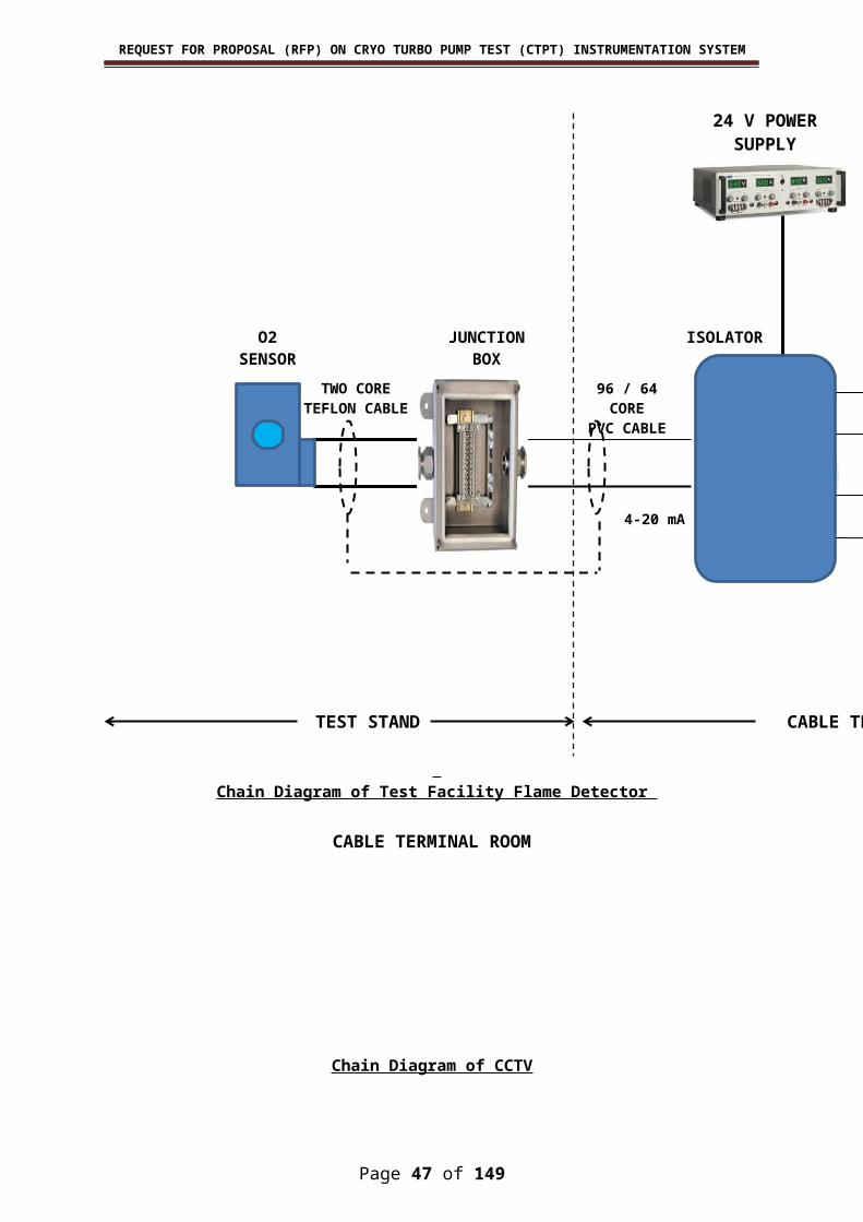
REQUEST FOR PROPOSAL (RFP) ON CRYO TURBO PUMP TEST (CTPT) INSTRUMENTATION SYSTEM
2 DTC 101 LOX 75 to 323 K3 DTC 102 LOX 75 to 323 K4 DTC 103 LOX 75 to 323 K5 DTC 104 LOX 75 to 323 K6 DTC 105 LOX 75 to 323 K7 DTC 110 LOX 75 to 323 K8 DTC 111 LOX 75 to 323 K9 DTC 120 LOX 75 to 323 K
10 DTC 121 LOX 75 to 120 K11 DTC 122 LOX 75 to 120 K12 DTC 123 LOX 75 to 120 K13 DTC 126 LOX 75 to 323 K14 DTC 130 LOX 75 to 120 K15 DTC 131 LOX 75 to 120 K16 DTC 132 LOX 75 to 323 K17 DTC 133 LOX 75 to 323 K18 DTC 160 LOX 75 to 323 K19 DTC 161 LOX 75 to 323 K20 DTC 162 LOX 75 to 120 K21 DTC 163 LOX 75 to 323 K22 DTC 180 LOX 75 to 323 K23 DTC 181 LOX 75 to 120 K24 DTC 182 LOX 75 to 323 K25 DTC 183 LOX 75 to 323 K26 DTC 200 LH2 15 to 323 K27 DTC 201 LH2 15 to 323 K28 DTC 202 LH2 15 to 323 K29 DTC 203 LH2 15 to 323 K30 DTC 204 LH2 15 to 323 K31 DTC 205 LH2 15 to 323 K32 DTC 210 LH2 15 to 323 K33 DTC 211 LH2 15 to 323 K34 DTC 220 LH2 15 to 323 K35 DTC 221 LH2 15 to 323 K36 DTC 222 LH2 15 to 100 K37 DTC 223 LH2 15 to 323 K38 DTC 230 LH2 15 to 323 K39 DTC 231 LH2 15 to 323 K40 DTC 232 LH2 15 to 323 K41 DTC 233 LH2 15 to 323 K42 DTC 260 LH2 15 to 323 K43 DTC 261 LH2 15 to 323 K44 DTC 262 LH2 15 to 100 K45 DTC 263 LH2 15 to 323 K46 DTC 270 LH2 15 to 323 K47 DTC 271 LH2 15 to 323 K48 DTC 272 LH2 15 to 323 K49 DTC 273 LH2 15 to 323 K50 DTC 274 LH2 15 to 323 K51 DTC 275 LH2 15 to 323 K52 DTC 310 LN2 75 to 323 K53 DTC 350 LN2 75 to 323 K54 DTC 351 LN2 75 to 323 K55 DTC 352 LN2 75 to 323 K56 DTC 522 GH2 273 to 1000 K
Page 47 of 117
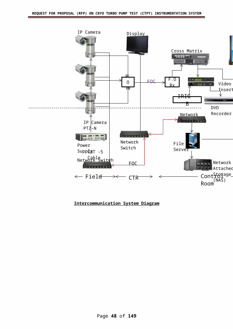
REQUEST FOR PROPOSAL (RFP) ON CRYO TURBO PUMP TEST (CTPT) INSTRUMENTATION SYSTEM
57 DTC 580 GH2 273 to 1000 K58 DTC 591 GH2 273 to 1000 K59 DTC 592 GH2 273 to 1000 K60 DTC 593 GH2 273 to 1000 K61 DTC 594 GH2 273 to 1000 K62 DTC 595 GH2 273 to 1000 K63 DTC 596 GH2 273 to 1000 K64 DTC 597 GH2 273 to 1000 K65 DTC 598 GH2 273 to 1000 K66 DTC 599 GH2 273 to 1000 K67 DTC SP1 LOX 75 to 323 K 68 DTC SP2 LH2 15 to 323 K 69 DTC SP3 LN2 75 to 323 K 70 DTC SP4 GH2 273 to 1000 K 71 DTC SP5
Spare channels are wired up to Junction Box
72 DTC SP673 DTC SP774 DTC SP875 DTC SP976 DTC SP1077 DTC SP1178 DTC SP1279 DTC SP1380 DTC SP1481 DTC SP1582 DTC SP1683 DTC SP1784 DTC SP18
Facility Measurement (Flow)1 DFQ 120 LOX 0 to 20 lps 442 DFQ 121 LOX 0 to 20 lps 443 DFQ 122 LOX 0 to 20 lps 444 DFQ 160 LOX 0 to 60 lps 25 DFQ 161 LOX 0 to 60 lps 26 DFQ 162 LOX 0 to 60 lps 27 DFQ 180 LOX 0 to 20 lps 1.78 DFQ 181 LOX 0 to 20 lps 1.79 DFQ 182 LOX 0 to 20 lps 1.7
10 DFQ 220 LH2 0 to 20 lps 2111 DFQ 221 LH2 0 to 20 lps 2112 DFQ 222 LH2 0 to 20 lps 2113 DFQ 260 LH2 0 to 175 lps 214 DFQ 261 LH2 0 to 175 lps 215 DFQ 262 LH2 0 to 175 lps 216 DFQ 270 LH2 0 to 75 lps 1.717 DFQ 271 LH2 0 to 75 lps 1.718 DFQ 272 LH2 0 to 75 lps 1.719 DFQ SP1 LH2 0 to 75 lps 1.720 DFQ 555 GH2 0 to 0.157 kg/s 3821 DFQ 556 GH2 0 to 0.157 kg/s 3822 DFQ 557 GH2 0 to 0.157 kg/s 3823 DFQ 738 GN2 0 to 10 kg/s 524 DFQ SP2 GH2 0 to 0.157 kg/s 3825 DFQ SP3 Spare channels are wired up to 26 DFQ SP4
Page 48 of 117

REQUEST FOR PROPOSAL (RFP) ON CRYO TURBO PUMP TEST (CTPT) INSTRUMENTATION SYSTEM
27 DFQ SP528 DFQ SP629 DFQ SP730 DFQ SP8
Test Article Measurement (Speed)1 DSP 101 0-36000 rpm2 DSP 102 0-36000 rpm 3 DSP 103 0-36000 rpm 4 DSP 104 0-36000 rpm 5 DSP 105 0-36000 rpm 6 DSP 106 0-36000 rpm 7 DSP 107 0-36000 rpm 8 DSP 108 0-36000 rpm9 DSP 109 0-36000 rpm
10 DSP 110 0-36000 rpm 11 DSP 111 0-36000 rpm 12 DSP 112 0-36000 rpm13 DSP 113 0-36000 rpm 14 DSP 114 0-36000 rpm 15 DSP 115 0-12000 rpm 16 DSP 116 0-12000 rpm17 DSP 117 0-12000 rpm 18 DSP 118 0-12000 rpm 19 DSP 119 0-12000 rpm 20 DSP 120 0-12000 rpm21 DSP 121 0-12000 rpm 22 DSP 122 0-12000 rpm 23 DSP 123 0-12000 rpm 24 DSP 124 0-12000 rpm25 DSP SP1
Spare channels are wired up to Junction Box
26 DSP SP227 DSP SP328 DSP SP429 DSP SP530 DSP SP6
Facility Measurement (Level)1 DLS 100 LOX 75 to 120 442 DLS 101 LOX 75 to 120 443 DLS 102 LOX 75 to 323 444 DLS 103 LOX 75 to 323 445 DLS 150 LOX 75 to 323 26 DLS 151 LOX 75 to 323 27 DLS O1 LOX 75 to 323 28 DLS O2 LOX 75 to 323 29 DLS O3 LOX 75 to 323 2
10 DLS O4 LOX 75 to 323 211 DLS O5 LOX 75 to 323 212 DLS O6 LOX 75 to 323 213 DLS O7 LOX 75 to 323 214 DLS O8 LOX 75 to 323 215 DLS O9 LOX 75 to 323 216 DLS O10 LOX 75 to 323 217 DLS O11 LOX 75 to 323 218 DLS O12 LOX 75 to 323 2
Page 49 of 117

REQUEST FOR PROPOSAL (RFP) ON CRYO TURBO PUMP TEST (CTPT) INSTRUMENTATION SYSTEM
19 DLS O13 LOX 75 to 323 220 DLS O14 LOX 75 to 323 221 DLS O15 LOX 75 to 323 222 DLS O16 LOX 75 to 323 223 DLS O17 LOX 75 to 323 224 DLS O18 LOX 75 to 323 225 DLS O19 LOX 75 to 323 226 DLS O20 LOX 75 to 323 227 DLS O21 LOX 75 to 323 228 DLS O22 LOX 75 to 323 229 DLS O23 LOX 75 to 323 230 DLS O24 LOX 75 to 323 231 DLS O25 LOX 75 to 323 232 DLS O26 LOX 75 to 323 233 DLS O27 LOX 75 to 323 234 DLS O28 LOX 75 to 323 235 DLS O29 LOX 75 to 323 236 DLS O30 LOX 75 to 323 237 DLS 200 LH2 15 to 323 2138 DLS 201 LH2 15 to 323 2139 DLS 202 LH2 15 to 323 2140 DLS 203 LH2 15 to 323 2141 DLS 250 LH2 15 to 323 1.742 DLS 251 LH2 15 to 323 1.743 DLS H1 LH2 15 to 323 244 DLS H2 LH2 15 to 323 245 DLS H3 LH2 15 to 323 246 DLS H4 LH2 15 to 323 247 DLS H5 LH2 15 to 323 248 DLS H6 LH2 15 to 323 249 DLS H7 LH2 15 to 323 250 DLS H8 LH2 15 to 323 251 DLS H9 LH2 15 to 323 252 DLS H10 LH2 15 to 323 253 DLS H11 LH2 15 to 323 254 DLS H12 LH2 15 to 323 255 DLS H13 LH2 15 to 323 256 DLS H14 LH2 15 to 323 257 DLS H15 LH2 15 to 323 258 DLS H16 LH2 15 to 323 259 DLS H17 LH2 15 to 323 260 DLS H18 LH2 15 to 323 261 DLS H19 LH2 15 to 323 262 DLS H20 LH2 15 to 323 263 DLS H21 LH2 15 to 323 264 DLS H22 LH2 15 to 323 265 DLS H23 LH2 15 to 323 266 DLS H24 LH2 15 to 323 267 DLS H25 LH2 15 to 323 268 DLS H26 LH2 15 to 323 269 DLS H27 LH2 15 to 323 270 DLS H28 LH2 15 to 323 271 DLS H29 LH2 15 to 323 272 DLS H30 LH2 15 to 323 273 DLS SP1 Spare channels are wired up to
Page 50 of 117

REQUEST FOR PROPOSAL (RFP) ON CRYO TURBO PUMP TEST (CTPT) INSTRUMENTATION SYSTEM
Junction Box
74 DLS SP275 DLS SP376 DLS SP477 DLS SP578 DLS SP679 DLS SP780 DLS SP881 DLS SP982 DLS SP1083 DLS SP1184 DLS SP1285 DLS SP13
Command System(EP Valve) 1 DVP 130 LOX 8 bar2 DVP 135 LOX 8 bar3 DVP 160 LOX 8 bar4 DVP 161 LOX 8 bar5 DVP 163 LOX 8 bar6 DVP 132 LOX 8 bar7 DVP 301 LN2 8 bar8 DVP 150 LOX 8 bar9 DVP 153 LOX 8 bar
10 DVP 105 LOX 8 bar11 DVP 535 GH2 8 bar12 DVP 730 GN2 8 bar13 DVP 230 LH2 8 bar14 DVP 235 LH2 8 bar15 DVP 237 LH2 8 bar16 DVP 260 LH2 8 bar17 DVP 261 LH2 8 bar18 DVP 263 LH2 8 bar19 DVP 268 LH2 8 bar20 DVP 253 LH2 8 bar21 DVP 232 LH2 8 bar22 DVP 270 LH2 8 bar23 DVP 271 LH2 8 bar24 DVP 202 LH2 8 bar25 DVP 205 LH2 8 bar26 DVP 200 LH2 8 bar27 DVP 207 LH2 8 bar28 DVP 220 LH2 8 bar29 DVP 221 LH2 8 bar30 DVP 223 LH2 8 bar31 DVP 264 LH2 8 bar32 DVP 266 LH2 8 bar33 DVP 210 LH2 8 bar34 DVP 211 LH2 NO 8 bar35 DVP 268 LH2 8 bar36 DVP 212 LH2 8 bar37 DVP 213 LH2 8 bar38 DVP 251 LH2 8 bar39 DVP 253 LH2 8 bar40 DVP 272 LH2 NO 8 bar41 DVP 224 LH2 8 bar42 DVP 226 LH2 8 bar
Page 51 of 117

REQUEST FOR PROPOSAL (RFP) ON CRYO TURBO PUMP TEST (CTPT) INSTRUMENTATION SYSTEM
43 DVP 262 LH2 NO 8 bar44 DVP 214 LH2 8 bar45 DVP 201 LH2 8 bar46 DVP 222 LH2 NO 8 bar47 DVP 300 LN2 8 bar48 DVP 315 LN2 8 bar49 DVP 700 GN2 8 bar50 DVP 107 LOX 8 bar51 DVP 167 LOX 8 bar52 DVP 101 LOX 8 bar53 DVP 103 LOX NO 8 bar54 DVP 104 LOX 8 bar55 DVP 100 LOX 8 bar56 DVP 102 LOX 8 bar57 DVP 113 LOX 8 bar58 DVP 120 LOX 8 bar59 DVP 121 LOX 8 bar60 DVP 123 LOX 8 bar61 DVP 180 LOX 8 bar62 DVP 181 LOX 8 bar63 DVP 110 LOX 8 bar64 DVP 111 LOX NO 8 bar65 DVP 112 LOX 8 bar66 DVP 340 LN2 8 bar67 DVP 506 GH2 8 bar68 DVP 320 LN2 8 bar69 DVP 164 LOX 8 bar70 DVP 166 LOX 8 bar71 DVP 350 LN2 8 bar72 DVP 116 LOX NO 8 bar73 DVP 122 LOX NO 8 bar74 DVP 124 LOX 8 bar75 DVP 125 LOX NO 8 bar76 DVP 126 LOX 8 bar77 DVP 127 LOX 8 bar78 DVP 557 GH2 8 bar79 DVP 558 GH2 8 bar80 DVP 559 GH2 8 bar81 DVP 560 GH2 8 bar82 DVP 131 LOX 8 bar83 DVP 162 LOX NO 8 bar84 DVP 114 LOX 8 bar85 DVP 115 LOX NO 8 bar86 DVP 133 LOX NO 8 bar87 DVP 165 LOX NO 8 bar88 DVP 350 LOX 8 bar89 DVP 151 LOX 8 bar90 DVP 168 LOX NO 8 bar91 DVP 291 LH2 8 bar92 DVP 265 LH2 NO 8 bar93 DVP 233 LH2 NO 8 bar94 DVP 236 LH2 NO 8 bar95 DVP 269 LH2 8 bar96 DVP 203 LH2 No 8 bar97 DVP 204 LH2 8 bar
Page 52 of 117
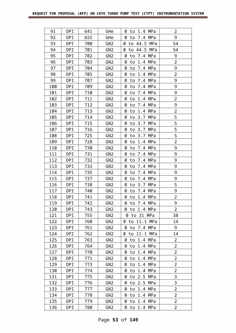
REQUEST FOR PROPOSAL (RFP) ON CRYO TURBO PUMP TEST (CTPT) INSTRUMENTATION SYSTEM
98 DVP 206 LH2 NO 8 bar99 DVP 225 LH2 NO 8 bar
100 DVP 215 LH2 NO 8 bar101 DVP 225 LH2 NO 8 bar102 DVP 403 GO2 8 bar103 DVP 137 LOX 8 bar104 DVP 136 LOX NO 8 bar105 DVP 351 LOX 8 bar106 DVP 517 GH2 8 bar107 DVP 519 GH2 8 bar108 DVP 529 GH2 8 bar109 DVP 321 LN2 8 bar110 DVP 311 LN2 8 bar111 DVP 302 LN2 NO 8 bar112 DVP 516 GH2 8 bar113 DVP 450 GO2 NO 8 bar114 DVP 518 GH2 8 bar115 DVP 550 GH2 NO 8 bar116 DVP 720 GN2 8 bar117 DVP 571 GH2 8 bar118 DVP 701 GN2 8 bar119 DVP 500 GH2 8 bar120 DVP 501 GH2 8 bar121 DVP 505 GH2 8 bar122 DVP 717 GN2 8 bar123 DVP 555 GH2 8 bar124 DVP 732 GN2 8 bar125 DVP 525 GH2 8 bar126 DVP 570 GH2 8 bar127 DVP 718 GN2 8 bar128 DVP 548 GH2 8 bar129 DVP 628 GHE 8 bar130 DVP 631 GHE 8 bar131 DVP 736 GN2 8 bar132 DVP 645 GHE 8 bar133 DVP 545 GH2 8 bar134 DVP 546 GH2 8 bar135 DVP 547 GH2 8 bar136 DVP 629 GHE 8 bar137 DVP 630 GHE 8 bar138 DVP 605 GHE 8 bar139 DVP 606 GHE 8 bar140 DVP 607 GHE 8 bar141 DVP 610 GHE 8 bar142 DVP 611 GHE 8 bar143 DVP 616 GHE 8 bar144 DVP 646 GHE 8 bar145 DVP 657 GHE 8 bar146 DVP 591 GH2 8 bar147 DVP 592 GH2 8 bar148 DVP 593 GH2 8 bar149 DVP 594 GH2 8 bar150 DVP 595 GH2 8 bar151 DVP 596 GH2 8 bar152 DVP 597 GH2 8 bar
Page 53 of 117
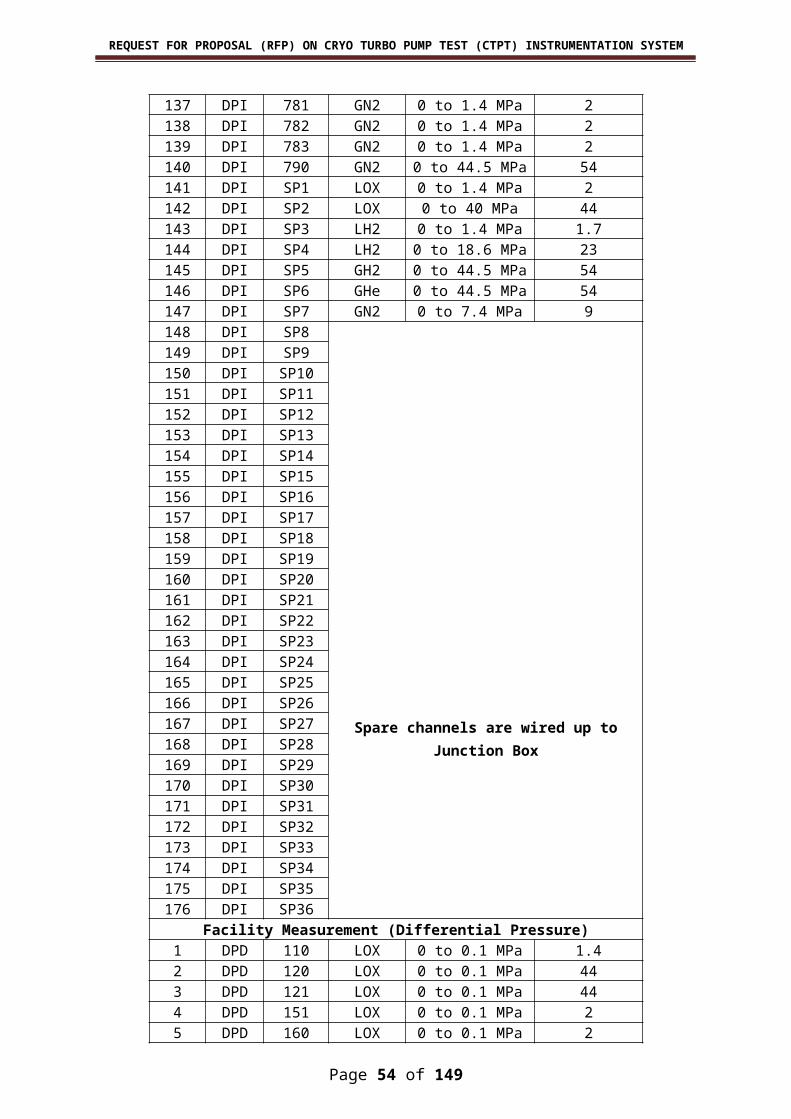
REQUEST FOR PROPOSAL (RFP) ON CRYO TURBO PUMP TEST (CTPT) INSTRUMENTATION SYSTEM
153 DVP 598 GH2 8 bar154 DVP 647 GHE 8 bar155 DVP 520 GH2 8 bar156 DVP 572 GH2 8 bar157 DVP 491 GO2 8 bar158 DVP 492 GO2 8 bar159 DVP 493 GO2 8 bar160 DVP 494 GO2 8 bar161 DVP 495 GO2 8 bar162 DVP 496 GO2 8 bar163 DVP 497 GO2 8 bar164 DVP 498 GO2 8 bar165 DVP 612 GHE 8 bar166 DVP 613 GHE 8 bar167 DVP 617 GHE 8 bar168 DVP 626 GHE 8 bar169 DVP 614 GHE 8 bar170 DVP 622 GHE 8 bar171 DVP 623 GHE 8 bar172 DVP 624 GHE 8 bar173 DVP 625 GHE 8 bar174 DVP 644 GHE 8 bar175 DVP 738 GN2 8 bar176 DVP 779 GN2 8 bar177 DVP 722 GN2 8 bar178 DVP 721 GN2 8 bar179 DVP 745 GN2 8 bar180 DVP 774 GN2 8 bar181 DVP 773 GN2 8 bar182 DVP 778 GN2 8 bar183 DVP 781 GN2 8 bar184 DVP 782 GN2 8 bar185 DVP 783 GN2 8 bar186 DVP 784 GN2 8 bar187 DVP 750 GN2 8 bar188 DVP 758 GN2 8 bar189 DVP 759 GN2 8 bar190 DVP 775 GN2 8 bar191 DVP 776 GN2 8 bar192 DVP 777 GN2 8 bar193 DVP 780 GN2 8 bar194 DVP 734 GN2 8 bar195 DVP 744 GN2 8 bar196 DVP 770 GN2 8 bar197 DVP 719 GN2 8 bar198 DVP 723 GN2 8 bar199 DVP 724 GN2 8 bar200 DVP 726 GN2 8 bar201 DVP 746 GN2 8 bar202 DVP 754 GN2 8 bar203 DVP HP1 GN2 48 bar204 DVP HP2 GN2 48 bar205 DVP HP3 GN2 48 bar206 DVP HP4 GN2 48 bar207 DVP HP5 GN2 48 bar
Page 54 of 117

REQUEST FOR PROPOSAL (RFP) ON CRYO TURBO PUMP TEST (CTPT) INSTRUMENTATION SYSTEM
208 DVP HP6 GN2 48 bar209 DVP HP7 GN2 48 bar210 DVP HP8 GN2 48 bar211 DVP HP9 GN2 48 bar212 DVP HP10 GN2 48 bar213 DVP HP11 GN2 48 bar214 DVP HP12 GN2 48 bar215 DVP HP13 GN2 48 bar216 DVP HP14 GN2 48 bar217 DVP HP15 GN2 48 bar218 DVP HP16 GN2 48 bar219 DVP HP17 GN2 48 bar220 DVP HP18 GN2 48 bar221 DVP HP19 GN2 48 bar222 DVP HP20 GN2 48 bar223 DVP HP21 GN2 48 bar224 DVP HP22 GN2 48 bar225 DVP HP23 GN2 48 bar226 DVP HP24 GN2 48 bar227 DVP HP25 GN2 48 bar228 DVP HP26 GN2 48 bar229 DVP HP27 GN2 48 bar230 DVP HP28 GN2 48 bar231 DVP HP29 GN2 48 bar232 DVP HP30 GN2 48 bar233 DVP HP31 GN2 48 bar234 DVP HP32 GN2 48 bar235 DVP HP33 GN2 48 bar236 DVP HP34 GN2 48 bar237 DVP HP35 GN2 48 bar238 DVP HP36 GN2 48 bar239 DVP HP37 GN2 48 bar240 DVP HP38 GN2 48 bar241 DVP SP1 Spare channels are wired up to
Junction Box
No- Normally Open Type
242 DVP SP2243 DVP SP3244 DVP SP4245 DVP SP5246 DVP SP6247 DVP SP7248 DVP SP8249 DVP SP9250 DVP SP10251 DVP SP11252 DVP SP12253 DVP SP13254 DVP SP14255 DVP SP15256 DVP SP16257 DVP SP17258 DVP SP18259 DVP SP19260 DVP SP20261 DVP SP21262 DVP SP22
Page 55 of 117

REQUEST FOR PROPOSAL (RFP) ON CRYO TURBO PUMP TEST (CTPT) INSTRUMENTATION SYSTEM
263 DVP SP23264 DVP SP24265 DVP SP25266 DVP SP26267 DVP SP27268 DVP SP28269 DVP SP29270 DVP SP30271 DVP SP31272 DVP SP32273 DVP SP33274 DVP SP34275 DVP SP35276 DVP SP36277 DVP SP37278 DVP SP38279 DVP SP39280 DVP SP40281 DVP SP41282 DVP SP42283 DVP SP43284 DVP SP44285 DVP SP45286 DVP SP46287 DVP SP47288 DVP SP48
Command System(Control Valve)1 DVC 230 LH2 8 bar2 DVC 200 LH2 8 bar3 DVC 250 LH2 8 bar4 DVC 262 LH2 8 bar5 DVC 260 LH2 8 bar6 DVC 261 LH2 8 bar7 DVC 220 LH2 8 bar8 DVC 221 LH2 8 bar9 DVC 130 LOX 8 bar
10 DVC 100 LOX 8 bar11 DVC 150 LOX 8 bar12 DVC 160 LOX 8 bar13 DVC 120 LOX 8 bar14 DVC 161 LOX 8 bar15 DVC 162 LOX 8 bar16 DVC 121 LOX 8 bar17 DVC 122 LOX 8 bar18 DVC 557 GH2 8 bar19 DVC 558 GH2 8 bar20 DVC 505 GH2 8 bar21 DVC 535 GH2 8 bar22 DVC 555 GH2 8 bar23 DVC 506 GH2 8 bar24 DVC 556 GH2 8 bar25 DVC 536 GH2 8 bar26 DVC 732 GN2 8 bar27 DVC 733 GN2 8 bar28 DVC 770 GN2 8 bar
Page 56 of 117

REQUEST FOR PROPOSAL (RFP) ON CRYO TURBO PUMP TEST (CTPT) INSTRUMENTATION SYSTEM
29 DVC 738 GN2 8 bar30 DVC 737 GN2 8 bar31 DVC 700 GN2 8 bar32 DVC 730 GN2 8 bar33 DVC 701 GN2 8 bar34 DVC 731 GN2 8 bar35 DVC SP1 GN2 8 bar36 DVC SP2 GN2 8 bar37 DVC SP3 GN2 8 bar38 DVC SP4 GN2 8 bar39 DVC SP5 GN2 8 bar40 DVC SP6 GN2 8 bar41 DVC SP7
Spare channels are wired up to Junction Box
42 DVC SP843 DVC SP944 DVC SP1045 DVC SP1146 DVC SP1247 DVC SP1348 DVC SP14
Page 57 of 117
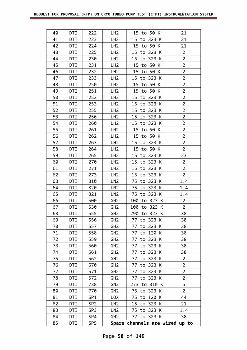
REQUEST FOR PROPOSAL (RFP) ON CRYO TURBO PUMP TEST (CTPT) INSTRUMENTATION SYSTEM
ANNEXURE III – INSTRUMENTATION SYSTEM SPECIFICATIONS
Page 58 of 117

REQUEST FOR PROPOSAL (RFP) ON CRYO TURBO PUMP TEST (CTPT) INSTRUMENTATION SYSTEM
1. SS tubes:
1. Type : Seamless SS tubes2. Outside Diameter : 12 mm/8 mm3. Wall Thickness : 2 mm for 12 mm/1.5 mm for 8 mm4. Total Length : As required5. Material Grade : ASTM A 269 TP 304/304L(Dual grade)6. Governing standards for Dimensions : ANSI B 36.197. Ends : Both the ends shall be plain with square cuts .All the burrs at the ends of tubes shall be removed.8. Test and Inspection : The tubes shall be tested and inspected as per ASTM standards in respect of material, visual inspection, Hydrostatic pressure test, Flattening test, Intergranular Corrosion test and Ultra sonic test / Eddy current test
as per ASTM E 426. Certificates to be provided prior to
supply for obtaining dispatch clearance from
the department.
9. Cleanliness : All the tubes shall be suitably cleaned / pickled and dried.10. Guarantee : The tubes shall be guaranteed for satisfactory performance against defects in material and forming over a period of 18 months from the date of despatch from the supplier’s work.11. Documentation : Test and guarantee certificate shall be provided. Certificates to be
provided prior to supply for obtaining dispatch clearance from the department.
2. Structural Material:
Structural Materials are as per IS 2062
AnglesISA 75 x 75 x 6ISA 65 x 65 x 6ISA 50 x 50 x 6
Channels ISMC 100
(Bolts, Screws, nuts, washers and clamps as per requirement)
Page 59 of 117

REQUEST FOR PROPOSAL (RFP) ON CRYO TURBO PUMP TEST (CTPT) INSTRUMENTATION SYSTEM
3. Aluminium Cable Gland:
Size ½, ¾ , 1 ,1 ¼ , 1 ½ and 2.Execution Ex d II CAmbient Temperature 15 deg C to 55 deg CProtection Degree IP66
Mechanical Characteristics:
Body / Cap : Anitcorodal AluminiumO-ring : silicon rubber Skid washer : nylon Chamber for sealing : OT-58 marine brass
4. Aluminium Plug:
Size ½, ¾ , 1 ,1 ¼ , 1 ½ and 2.Execution Ex d II CAmbient Temperature 15 deg C to 55 deg CProtection Degree IP66
Mechanical Characteristics:
Body / Cap : Anitcorodal Aluminium
5. SOV cubicle with Explosion proof Junction Box (2 Nos) including electrical terminals for mounting dual coil solenoid valve
1 Type Type : I, Cubicle with 5 dual coil SOV and Main and Redundant JBType : II, Cubicle with 10 dual coil SOV and Main and Redundant JB
2 Enclosure protection Weather Proof to IP 66 & Explosion proof to IIC, T6
3 Material Stainless Steel / Aluminium Alloy4 Cover Hinged for SOV cubicle and bolted for JB5 Body Grounding Earthing Screws of SS material with
washer6 Dimension Type : I - 700 mm (W) x 1150 mm (H) x
350 mm (D) (approximate)Type : II - 950mm (W) x 1150mm (H) x 350mm (D) (approximate)
Terminals
Page 60 of 117

REQUEST FOR PROPOSAL (RFP) ON CRYO TURBO PUMP TEST (CTPT) INSTRUMENTATION SYSTEM
7 No. of terminals Type : I - 15(Each size 2.5 mm2). One Insulated Tinned Copper shield busbar having 10 Nos. of M6 screw should be provided to terminate shield of cable.Type : II - 30(Each size 2.5 mm2). One Insulated Tinned Copper shield busbar having 10 Nos. of M6 screw should be provided to terminate shield of cable.
Additional terminals for status indication.8 Style Screwed, Clip on type9 Mounting On DIN Rail with End stoppers.
10 Cable Glands 10.1 No. of cable entry
(Main & Redundant)1 per Main Junction Box (For Field)1 per Redundant Junction Box (For Field)
10.2 No. of cable entry (Branch)
Field : 1 per SOV per Junction BoxAt SOV end : 1 per SOV
10.3 Type of Cable Glands Field: Double Compression type, WP to IP 65 & Ex proof to IIC. Within Cubicle for SOV : Single Compression type
11 PVC Hood for Cable Glands
Each Cable glands to be supplied with suitable sized PVC hood.
12 Cable Entry Multi Pair Cable entry – Bottom of JBBranch Cable entry – equally distributed at both side of JB
General13 Pneumatic connection Suitable for fixing of Bulk head union for
½ “ female NPT for 8 mm OD SS tubes All the entries shall be plugged with SS plug.
14 Interconnection The SOV cubicle & Ex proof JB to be interconnected by Sealed nipple or cables should be passed through nipple & properly glanded at JB.
15 Tag Plate SS tag plate fixed firmly on the front face of the cubicle & JB Cover, indicating tag number.
16 Certification ATEX Zone 1, EX d, IIC, CIMFR 17 Remarks
[The required cubicle assembly is shown in the figure 1]
The GA drawings of cubicle with JB, indicating SOV mounting & tubing to be submitted for approval before manufacturing. Manufacturing shall be done as per the drawing approved along with the order specifications. Despatch clearance shall be obtained before supplying the item to IPRC.
18 Welding of command Header
All welding shall be carried out with TIG welding argon as inert gas.
19 Header Irrespective of type, maximum allowed pressure shall be 74 bar.
Page 61 of 117

REQUEST FOR PROPOSAL (RFP) ON CRYO TURBO PUMP TEST (CTPT) INSTRUMENTATION SYSTEM
Page 62 of 117
Tig Welding

REQUEST FOR PROPOSAL (RFP) ON CRYO TURBO PUMP TEST (CTPT) INSTRUMENTATION SYSTEM
Type I (5 Nos dual coil solenoid)
Page 63 of 117
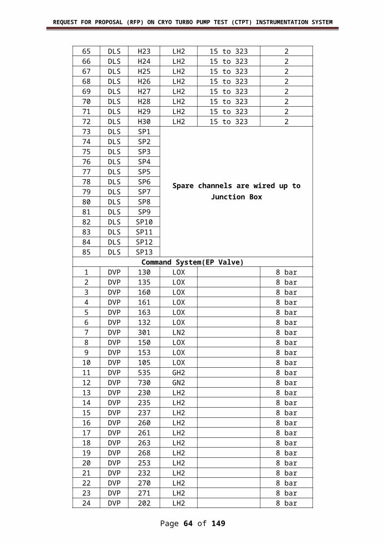
REQUEST FOR PROPOSAL (RFP) ON CRYO TURBO PUMP TEST (CTPT) INSTRUMENTATION SYSTEM
Type II (10 Nos dual coil solenoid)
Page 64 of 117

REQUEST FOR PROPOSAL (RFP) ON CRYO TURBO PUMP TEST (CTPT) INSTRUMENTATION SYSTEM
6. Dual coil Solenoid valve single acting:
1 Designation / Operation 3 port 2 way / Solenoid Valve / Normally Close (NC) Category I: Low pressure 10 bar MAWPCategory II: High pressure 60 bar MAWP
2 Type Direct / Pilot operated Solenoid Valve with dual redundant coil. (Valve should be energised with both or either of coils is powered. It should only be closed if both coils are not powered.)
3 Design / Construction 3/2 way (In, Out & Exhaust)4 Operating Voltage 24V ± 3V DC 5 Service Gaseous Nitrogen6 Operating Pressure 7 bar for low pressure & 48 bar for high
pressure 7 Response Time 100ms (Maximum)8 Power Consumption Max. 12 Watt9 Service Life Greater than 50,000 Operations
10 End Connections 1/4” NPT (F)11 Electrical Connection ½” NPT (F)12 Time for Continuous
Operation24 Hours
13 Insulation Resistance >100 MΩ at 500V DC14 Coil Insulation Class H15 Pull-in voltage 18±1V DC16 Drop out voltage 10±1V DC17 Operating Temperature 273 to 318 K18 Manual Override To be provided by screw – One per SOV19 Area Classification NEC Class 1, Div. 1, Gas Gr. B, Temp.
Class T620 Enclosure Protection Explosion-Proof to EExd IIC, T6, Zone 1,
EN 50018 of IEC / CENELEC and WP to IP 67
21 Orifice 1.2 mm ± 1%22 Seat Material VITON/PTFE23 Material body SS316/12x18H10T24 Mounting Panel mounting type bracket along with
accessories to be supplied with each SOV.
25 Terminals Suitable for 2.5 mm2 cables 26 Housing Die Cast Aluminium Epoxy Painted27 Silencer / Muffler To be fitted on Exhaust port28 Special Feature Free wheeling Diode across each Coil
29 Tag Plate SS indicating Tag No, Model No., Sr. No, End Connection etc.
Page 65 of 117

REQUEST FOR PROPOSAL (RFP) ON CRYO TURBO PUMP TEST (CTPT) INSTRUMENTATION SYSTEM
7. Junction Box :
1 Enclosure protection Weather Proof to IP 66 & Explosion proof to IIC
2 Material Stainless Steel3 Cover Hinged and bolted with Neosprene gasket 4 Body Grounding Earthing Screws of SS material with washer.5 Dimension Type I : 500 (H) x 500 (W) x 225 (D)
approximateType II : 775 (H) x 525 (W) x 225 (D) approximate
Terminals :6 No. of terminals Type I : 108 Terminal blocks
Type II : 216 Terminal blocks7 Type Each size 2.5 mm2 , Clamp on mechanism
with screw less type (Phoenix / Weidmuller) to be supplied along with JB.
8 Mounting On DIN Rail with end stoppers with cable duct9 Shield Bar 25 x 3 mm, Tinned Copper, Mounted on
Insulated supports having M6 tapings – 25 Nos.
Cable Glands / Plugs :10 No. of cable entry Type I : Equally distributed at both side of JB
48 Nos of ½ “/ ¾ “ and 2 nos of 2” Type II : Equally distributed at both side of JB 48 Nos of ½ “/ ¾ “ and 3 nos of 2”. Suitable Reducer for accommodating lower size gland in the higher size cable entry is party’s scope.
11 Type Aluminium , Double Compression type, WP to IP 66 & Ex proof to IIC.
12 Plugs Aluminium, WP to IP 66 & Ex proof to IIC.13 PVC Hood for Cable
GlandsEach Cable glands to be supplied with suitable sized PVC hood.
14 Marking Cable OD & size has to be marked on each cable gland. Size has to be marked on each plug.
General :15 Tag Plate SS tag plate fixed firmly on the front face of
the cover, indicating tag number.16 Certification The junction boxes, Cable Glands & Plugs
shall be certified for installation at Group II C area.
17 Remarks The GA drawings of cubicle with JB to be submitted for approval before manufacturing. Manufacturing shall be done as per the drawing approved along with the order specifications. Despatch clearance shall be obtained before supplying the item to IPRC.
Page 66 of 117

REQUEST FOR PROPOSAL (RFP) ON CRYO TURBO PUMP TEST (CTPT) INSTRUMENTATION SYSTEM
8. Cable Tray:
Types : Ladder type 500 mm width, 150 mm Depth.
Perforated cable tray 50 mm width, 25 mm Depth 100mm width, 50 mm depth/ 150mm width, 75 mm depth/ 300 mm width, 100 mm depth.
Length : 2.5 mtr per piece Raw Material : MS conforming to IS 1079.Thickness : 3 mmFinish : Self-finish, Pre-galvanized, Hot Dip
Galvanising as per IS 2629 / 4759. Coupler Plates : 2 nos per tray with required hardware (nuts, bolts and washers)Note :
1. All dimensional tolerances shall be as per IS 1852.2. Chemical test certificates for Zinc deposition and thickness of deposit shall
be as per IS 6475 – 19723. Adhesion test shall be as per IS 2629 – 1985.4. Uniformity of Zinc coating shall be as per IS 2633 – 1972.5. All certificates shall be from Government approved laboratories along with
delivery of item without additional cost.
9. Electronic Pressure switch suitable for IIC applications:
Type : Pressure switch with DPDTInput:
1. Set Pressure range : I : 4 - 8bar absolute : II : 40 – 48bar absolute
2. Max operating pressure : I : 11 bar absolute : II : 74 bar absolute
3. Over Pressure : 2 times Max. operating Pressure4. Burst Pressure : 3 times Max. operating Pressure5. Wetted Part : Stainless steel suitable for GN2
Output:1. Electrical output : Potential free contact2. Excitation : 24 VDC3. Switching electrical rating : 24 VDC/50 mA4. Switch operating mode : Normally open5. Set point accuracy : ≤ 2% of set pressure6. Dead band : ≤ 1% of set pressure
Page 67 of 117

REQUEST FOR PROPOSAL (RFP) ON CRYO TURBO PUMP TEST (CTPT) INSTRUMENTATION SYSTEM
Environmental:1. Construction : Hermetically sealed explosion proof to
EExd IIC2. Operating Temperature : -55 deg C to +70 deg C3. Humidity : 100 % RH4. Mechanical shock : 50 g
Physical:1. Electrical connection ½” NPTF2. Process connection ½” NPTM
10.Powder coated MS sheet :
1. Powder coated Canopy for roof (MS sheet of Thickness 1.5 mm and width varying from 500 to 750 mm suitable for Junction boxes, Pressure / Tem-perature transmitters and Cubicles)
2. Powder coated MS sheet of Thickness 2 mm and width varying from 600 to 1200 mm suitable for mounting DIN Rail, PVC Cable duct and connectors in instrumentation rack
3. Powder coated MS Sheets 6mm Thick 800 mm x 330 mm size for cable entry plate and Fixing of cable glands in cable entry point in SCR and con-trol room (Necessary glands, RTV compounds, M-seal for cable entry are party’s scope)
11. GI Pipe:
Size : 2 “ Length : 6 mtrs long standardThickness : 3.25 mmClass : ‘B’ IS 1239
12. Electro Magnetic DPDT Relays:
Type :Electro Mechanical Moulded Relay with relay mounting LED indication socket and accessories
Operation voltage : 24 V DCNo. of poles : DPDT, 2 pole [NO, COM, NC]Construction : Supply status indication LED,
Freewheeling diode Reverse polarity protection diodes shall be assembled as integral part of the socket
Coil specificationNominal input voltage : 24 V DCNominal input current : ≤ 20 mASupply status indication : LED is to be providedFreewheeling : Diode is to be providedReverse polarity protection : Diode is to be provided at the
positive terminal of coil
Page 68 of 117

REQUEST FOR PROPOSAL (RFP) ON CRYO TURBO PUMP TEST (CTPT) INSTRUMENTATION SYSTEM
Contact specificationLimiting continuous current : 6 ampsMaximum inrush current : 8 ampMaximum switching voltage : 250 V DCMinimum switching current : 10 mAPower rating (ohmic load) : ≥ 140 WContact material : AgNi
Technical dataMechanical life : ≥ 3 X 10⁷ cyclesResponse time : ≤ 8 msRelease time : ≤ 10 ms
Electrical Isolationa) relay winding/relay contact : 4 kV ACb) PDT/PDT : 2.5 kV AC
Ambient temperature range : Upto 60ºCProtection category : IP67Connection DataType of connection : Screw connectionMin. conductor cross section, rigid : 0.14 mm2
Conductor cross section, rigid max : 2.5 mm2
Conductor cross section, flexible : 0.14 mm2
Max. Conductor cross section, flexible : 2.5 mm2
Min. conductor cross section AWG/kcmil : 26Conductor cross section AWG/kcmil max : 14Stripping length : 8 mmScrew thread : M 3General:Mounting : 35 mm DIN rail mountingAccessories : Short links (~500mm length)Identification label : Provision is to be providedRemoval of relay : Provision is to be provided toRemove the relay from socketHousing insulation material : Polyamide PA non- reinforced
Standards/regulations : IEC 60 664/IEC 60 664 A/DIN VDE 0110, Contamination
class2, surge voltage category III, DIN VDE 0106-101: 1986- 11, increased Isolation I/O.
Approvals/Certification : Relay modules shall have approval and certificate confirms to UL508,EN61810-1GL standard.
13. Siemens Contactor:
Make : Siemens make SICONT plus contactor
Model No. : 3TH30 (3TH3040-0BB4) – Main Contact (3TX4001-2A) – Auxillary Contact.
Page 69 of 117

REQUEST FOR PROPOSAL (RFP) ON CRYO TURBO PUMP TEST (CTPT) INSTRUMENTATION SYSTEM
Main Contact : 4 NOAuxillary Contact : 4 NCCoil Voltage : 24 V DCRated Coil Input Power : 6.2 WRated impulse withstand voltage : 8 KVPermissible ambient temperature : 0 – 55 deg CMechanical Cycles : 30 millionsMain contact rated operating current at 240 V AC : 10 AMain contact (NO) rated operating current at DC 24 V : 10 AAuxillary contact (NC) rated operating current at DC 24 V : 2 A
14. Hall Effect Sensor for Current Measurement with Mounting PCB
CURRENT TRANSDUCER Measuring Range : I : 0 to 3A
II : 0 to 10A III: 0 to 20A
Output voltage : 0 to 4V Output impedance : < 50 Ω Load resistance : ≥10 kΩSupply voltage : ± 15 V Accuracy : < ± 1 % Response time : 3 µs Ambient operating temperature : 0 to + 85 °C ·Make : LEM
Current Sensor cards 35 mm Din rail mountable current sensor cards. Separate set of Input / Output & Power TBs of phoenix make are to be
fabricated on the PCB along with Identification Tags. Din rail mount card holder to be provided. LEDs should be provided for supply indication. 8/16 Nos of Hall sensors shall be mounted in PCB and shall have input,
output and power supply connectors.
15. Double deck dual diode clamp on Terminal Blocks
a) Type : Clamp on mechanism with screw -less system(Phoenix type).
b) Size AWG : 20 c) No: of levels : 2d) No: of terminals : 4 e) Contact rating
i) Nominal Current : ≥ 20 A ii) Nominal Voltage : ≥ 500 V
iii) Rated Surge Voltage : ≥ 6 kVf) Width : ≤ 5.2 mm (W)g) Wire Entry : Front side.
h) Mounting : 35 mm Din Rail.i) 1) Certification : CSA, UL
Page 70 of 117
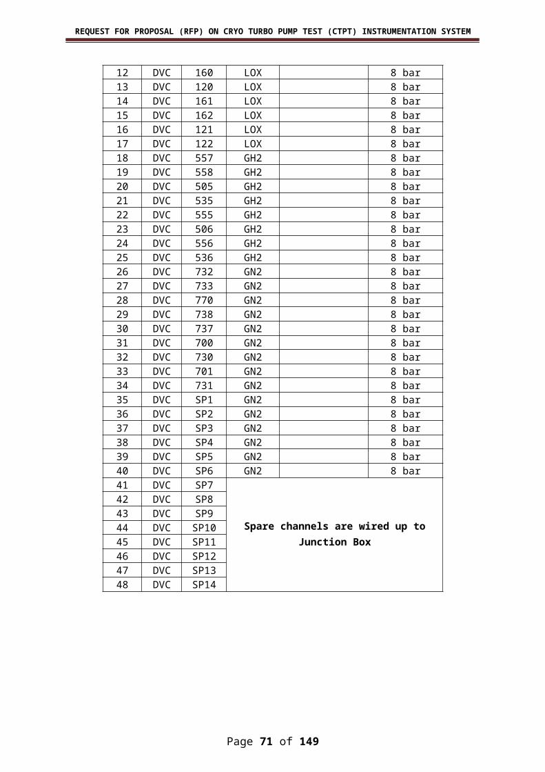
REQUEST FOR PROPOSAL (RFP) ON CRYO TURBO PUMP TEST (CTPT) INSTRUMENTATION SYSTEM
2) Certification, Ex : IECEx.j) Pollution Degree : 3.k) Diode part number : IN 4007l) Mounting : 35 mm Din Rail.m) Color : Grey.
Terminal Block Accessories:1. Short Links 2. End Stop3. End Plate4. Suitable DIN rail with required length should be supplied along with
the terminal block.5. Marking ferrules6. Screw driver for handling terminal blocks 3 Nos
16. Double deck clamp on Terminal Blocks :
a) Type : Clamp on mechanism with screw less system (Phoenix type).
b) Size AWG : 20 c) No: of levels : 2d) No: of terminals : 4 e) Color : Greyf) Contact rating :
i) Nominal Current : ≥ 20 A ii) Nominal Voltage : ≥ 500 Viii) Rated Surge Voltage : ≥ 6 kV
g) Wire Entry : Front side.h) Width : ≤ 5.2 mm (W)i) Mounting : 35 mm Din Rail.j) 1) Certification : CSA, UL
2) Certification, Ex : IECExk) Pollution Degree : 3.
Terminal Block Accessories:1. Short Links 2. End Stop3. End Plate4. Suitable DIN rail with required length should be supplied along with
the terminal block.5. Marking ferrules6. Screw driver for handling terminal blocks 3 Nos
17. Single deck cage clamp type Terminal block
a) Phase : Red b) Neutral : Black c) Earth : Green +Yellow d) Type : Stainless Steel clamping
mechanism with screw less system (Phoenix type).
e) Size : AWG 16.f) No: of terminals : 2
Page 71 of 117

REQUEST FOR PROPOSAL (RFP) ON CRYO TURBO PUMP TEST (CTPT) INSTRUMENTATION SYSTEM
g) Contact Ratingi. Nominal Current : ≥ 20 A ii. Nominal Voltage : ≥ 500 Viii. Rated Surge Voltage : ≥ 6 kViv. Current rating : 8Av. Voltage rating : 440 V
h) Wire Entry : Front Side.i) Width : <8 mm.j) Mounting : 35 mm Din Rail.
Terminal Block Accessories:1. Short Links 2. End Stop3. End Plate4. Suitable DIN rail with required length should be supplied along with
the terminal block.5. Marking ferrules6. Screw driver for handling terminal blocks 3 Nos
18. Crimp terminals:Type : Insulated crimp terminalsTerminal material : Tin plated copperSleeve material : NylonCompliance : RoHS
Tubular:AWG 26,24,20,18,16 and 12
Spade:AWG 20,18,16 and 12
Flat Tab:AWG 18,16 and 12
Butt Splices:AWG 26, 24, 20, 18,16 and 12
Accessories:5 Nos of crimping tool to be supplied along with terminals.
19. Moulded 5 A Power Cable with socket (Equipment End):
Standard Power connector for providing 230V operated equipments (3 pin)
Moulded type
20. 3 core armoured power cable: PVC insulated multi-core armoured electrical cable
Color : blackConductor : bright annealed copperSize : 2.5 sq.mmVoltage grade : 1100V
PREFERRED MAKE:
1. POLYCAB2. FINOLEX3. FYBROS
Page 72 of 117

REQUEST FOR PROPOSAL (RFP) ON CRYO TURBO PUMP TEST (CTPT) INSTRUMENTATION SYSTEM
21. 3 core power cable of 2.5 sq.mm:
PVC insulated multi-core electrical cable Color : blackConductor : bright annealed copperSize : 2.5sq.mmVoltage grade : 1100V
PREFERRED MAKE:
1. POLYCAB2. FINOLEX3. FYBROS
22. Console push button switches:
Rating : 3 A at 24 VDCContacts : DPDTMounting : Console typeIndicator : 24 V DC (ON red / OFF green )Insulation Resistance : 100 MΩ min. (at 500V DC)Contact Resistance : 100 mΩ max. (initial value)Operating temperature : 15 – 55 deg C
23. Console Key lock switch:
Rating : 4 A at 24 VDCContacts : DPDTMounting : Console typeIndicator : 24 V DC (ON red / OFF green )Insulation Resistance : 100 MΩ min. (at 500V DC)Contact Resistance : 100 mΩ max. (initial value)Operating temperature : 15 – 55 deg C
24. Indicators:
Incandescent lamp : 28 VAC/VDC,1.2 W max.Insulation Resistance : 100 MΩ min. (at 500V DC)Operating temperature : 15 – 55 deg C
25. Industrial wet and dry Vaccum cleaner with 23 litres stainless steal bin and standard accessories:
Capacity : 23 ltrFilter : additional 1 set of spare filter
should be provided
26. Co-axial Cable:Cable type : Video RG 59/UInner conductor : 0.58 mm
Solid Bare CopperInner conductor DCResistance : 47 ohms / mInsulation and Nominal core Dia : Polyethylene, 3.7 mmNominal O.D of cable : 6.15 mm
Page 73 of 117

REQUEST FOR PROPOSAL (RFP) ON CRYO TURBO PUMP TEST (CTPT) INSTRUMENTATION SYSTEM
Number of shielded Material : Single bare copper braidShield coverage, Resistance : 95% shield coverage
2.6ohms/m Nominal Impedance : 75 OhmsNominal Velocity ofPropagation : 66 %Nominal capacitance : 67 PF / mtNominal Attenuationat 200 MHz : 16 dB / 100 mtNominal Outer PVCColour : Grey or BlackMaximum Operating Voltage RMS : 300 V
27. Cat6 Cable:
Length : 305 M Length / BoxConstruction : 4 twisted pairs separated by
polymer spineType : Cat 6 PVC cableConductor Type : 23 AWG Solid bare copperSupport : Gigabit Ethernet 1000 Base-TFrequency : 1-250 MHzAttenuation(Insertion Loss) : 14 dB or better (at 100 MHz)NEXT : 58.7 dB or better (at 100 MHz)ELFEXT : 41.2 dB or better (at 100 MHz)Return Loss : 23.1 dB or better (at 100 MHz)Characteristic Impedance : 100 ± 15 ohmsStandards : UL, ETL, RoHS, CM rated,
TIA/EIA 568-C2, ISO/IEC 11801
28. Multipin Connectors (72 pin/108 pin) sets:1. Inserts (Male & Female):
No. of Poles : I : 72 : II: 108
Rated Voltage to UL/CSA : 600 VRated current : 10 ARated impulse withstand voltage : 4 kVPollution severity : 3 (Conductive pollution, or dry,
non-conductive pollution that is liable to be rendered conductive thru condensation)
Insulation resistance : ≥ 1010 ohm Material : Glass fiber reinforced Poly
Carbonate Temperature Range : -40 oC …. +125 oCFlammability to UL 94 : V 0 Mechanical service life : ≥ 500 mating cycles
Page 74 of 117

REQUEST FOR PROPOSAL (RFP) ON CRYO TURBO PUMP TEST (CTPT) INSTRUMENTATION SYSTEM
2. Hoods Materials : Die-Cast AluminumSurface : Powder coated RAL 7037(Grey)Flammability to UL 94 : V 0 Cable entry : Bottom/TopCable entry dia : M32Protection : IP65
3. Base Housing (bulk head)Material : Die-Cast AluminumSurface : Powder coated RAL 7037(Grey)Flammability to UL 94 : V 0 Locking Mechanism : Double latchLocking material : Stainless SteelCable entry Dia : M32Protection : IP65
4. Standards & Certifications Certification : UL, CSA or equivlent Standard : DIN EN 60 664.1
DIN EN 61 9845. Cable Entry Gland
With suitable cable gland/clamp with strain relief features Material/Colour : Polyamide 6/RAL 7035Temperature range : -20C….80CClass of protection : IP 65The thread shall suit to the cable entry points at the Hood and Housing.
6. Sealing Plug Material/Colour : Polyamide 6/RAL 7035Temperature range : -20C….80CSize : M32
The thread shall suit to the cable entry points at the Hood and Housing
7. ToolsCrimping tool to be supplied along with connectors : 5 nosExtraction tool : 10 nos
PREFERRED MAKE:
1. WEIDMULLER2. HARTING3. AMPHENOL
Page 75 of 117

REQUEST FOR PROPOSAL (RFP) ON CRYO TURBO PUMP TEST (CTPT) INSTRUMENTATION SYSTEM
29. Female crimping contact:Type : CrimpContact Material : Copper alloy-hard gold plated
Au over NiGold plating thickness : 0.8 μm Ni thickness : 2 μm (Min)Contact size : 18 AWG to 26 AWGWorking Current : 10 AWorking voltage : 600 VInsulation resistance : ≥ 100 M ohmContact resistance : ≤ 4 milli OhmCrimp connection
Stripping length : 8.0 mm
30. Male crimping contact:Type : CrimpContact Material : Copper alloy-hard gold plated
Au over NiGold plating thickness : 0.8 μm Ni thickness : 2 μm (Min)Contact size : 18 AWG to 26 AWGWorking Current : 10 AWorking voltage : 600 VInsulation resistance : ≥ 100 M ohmContact resistance : ≤ 4 milli OhmCrimp connection Stripping Length : 8.0 mm
31. Technical Specifications for Instrumentation Racks.SYSTEM CHARACTERISTICS
19" Floor standing rack with sub rack mounting plane, adjustable to suit user's requirement, These racks offer standard 19 inch fixing rail with frame. The server racks provide an effective way of aggregating a large number of servers. and manufactured with high quality materials that are durable and produced by following stringent quality inspection at all stages of production that meets ISO standards of 9001-2008. Entire prod-uct range are flexible, scalable, and versatile with optimization hall mark exhibiting excellence of product and utility.
Special Features:
The doors and side covers concealed type All the three axes members are directly coupled to each other to give
a good rigidity Easy mounting of all non-standard electrical installations Orderly and space saving cable routing (top and bottom) The Cooling Arrangement in line with the heat dissipation Airflow can be specifically adopted to the installed components Temperature Indicator with remote Digital o/p
Finish : Powder Coated with standard RAL colour options
Page 76 of 117

REQUEST FOR PROPOSAL (RFP) ON CRYO TURBO PUMP TEST (CTPT) INSTRUMENTATION SYSTEM
31.1 Data Sheet of Instrumentation rack - Single rack
Sl.no Details Description
1. Size Single Rittal Rack: 2000mm(H) x 600mm(W) x 800mm(D)
2. Material type Sheet steel3. Standard Color RAL 70354. Enclosure frame Epoxy Powder coated finish5. Enclosure panels Epoxy Powder coated finish
6. Doors, front and rearSingle rack: 1 leaf Front: toughened glassRear: perforated sheet steel
7.Mounting angles, mounting frame & punched sections with mounting flanges. Inter hole distance of 1U
Zinc-plated
8.
482.6 mm (19˝) level, flat mounting angles on punched sections with mounting flanges, front and rear, depth-variable
2 Nos.
9.482.6 mm (19˝) level, flat mounting frames front & rear, depth-variable
2 Nos.
10. Provision for cable entry from false floor
to be provided with punched base plate
11.Cooling fan, 230 V AC 250 CFM, (bottom left & top right) with air filter
2 Nos.
12. Side panels, lockable 2 Nos.13. Side panel, plug-type, divided 1 Nos.
14. Base mounting bracket frame100mm Height Frame with 600mm x 800mm clearance for cable entry and to comply the specifications in IS-513
15. Comfort handle with security lock shall be provided for front and rear doors. Internal Lighting to be provided with On/Off switch.
16 Accessories per Rack: L-angle – 8 setsFiller plates – 1U 5 Nos , 2U 3 Nos, 4U 2 Nos, 6U 1 No
Page 77 of 117

REQUEST FOR PROPOSAL (RFP) ON CRYO TURBO PUMP TEST (CTPT) INSTRUMENTATION SYSTEM
Keyboard Tray – 1 NoMounting Fasteners (Captive mounting nuts & screws 50 Nos per pack) – 5 packs
31.2 Data Sheet of Instrumentation rack - Double rack
Sl.no Details Description
1. Size Double Rittal Rack: 2000mm(H) x 1200mm(W) x 800mm(D)
2. Material type Sheet steel3. Standard Color RAL 70354. Enclosure frame Epoxy Powder coated finish5. Enclosure panels Epoxy Powder coated finish
6. Doors, front and rearDouble Rack : 2 leafFront: toughened glassRear: perforated sheet steel
7.Mounting angles, mounting frame & punched sections with mounting flanges. Inter hole distance of 1U
Zinc-plated
8.
482.6 mm (19˝) level, flat mounting angles on punched sections with mounting flanges, front and rear, depth-variable
2 Nos.
9.482.6 mm (19˝) level, flat mounting frames front & rear, depth-variable
2 Nos.
10. Provision for cable entry from false floor
to be provided with punched base plate
11.Cooling fan, 230 V AC 250 CFM, (bottom left & top right) with air filter
2 Nos.
12. Side panels, lockable 2 Nos.13. Side panel, plug-type, divided 1 Nos.
14. Base mounting bracket frame100mm Height Frame with 1200mm x 800mm clearance for cable entry and to comply the specifications in IS-513
15. Comfort handle with security lock shall be provided for front and
Page 78 of 117

REQUEST FOR PROPOSAL (RFP) ON CRYO TURBO PUMP TEST (CTPT) INSTRUMENTATION SYSTEM
rear doors. Internal Lighting to be provided with On/Off switch
16.
Accessories per Rack: L-angle – 8 setsFiller plates – 1U 5 Nos , 2U 3 Nos, 4U 2 Nos, 6U 1 NoMounting Fasteners (Captive mounting nuts & screws 50 Nos per pack) – 5 packs
31.3 Data Sheet of Instrumentation rack - Server rack
Sl.no Details Description
1. SizeSingle Rittal Server Rack 2000mm(H) x 600mm(W) x 1000mm(D)
2. Material type Sheet steel3. Standard Color RAL 7035 4. Enclosure frame Epoxy Powder coated finish5. Enclosure panels Epoxy Powder coated finish
6. Doors, front and rearFront: toughened glassRear: perforated sheet steel, 78% perforated
7.Mounting angles, mounting frame and punched sections with mounting flanges. Inter hole distance of 1U
Zinc-plated
8.482.6 mm (19˝) level, flat mounting angles on punched sections with mounting flanges, front and rear, depth-variable.
2 nos.
9.482.6 mm (19˝) level, flat mounting frames front and rear, depth-variable
2 nos.
10. Provision for cable entry from false floor
to be provided with punched base plate
11. Cooling fan, 230 V AC 250 CFM 2 Nos., (bottom left & top right)
12. Side panels, lockable 2 Nos.13. Side panel, plug-type, divided 1 Nos.
14. Base mounting bracket frame100mm Height Frame with 600mm x 1000mm clearance for cable entry and to comply the specifications in IS-513
Page 79 of 117

REQUEST FOR PROPOSAL (RFP) ON CRYO TURBO PUMP TEST (CTPT) INSTRUMENTATION SYSTEM
15. Comfort handle with security lock shall be provided for front and rear doors. Internal Lighting to be provided with On/Off switch
16.
Accessories per Rack: L-angle – 8 setsFiller plates – 1U 5 Nos , 2U 3 Nos, 4U 2 Nos, 6U 1 NoKeyboard Tray – 1 NoMounting Fasteners (Captive mounting nuts & screws 50 Nos per pack) – 5 packs
32 Supply and installation of Storage racks
Size : 1950mm(H)X915mm(L)X470mm(D) with 8 holesProduct Description : Side ,back and door will be 0.8 mm CRCA sheet. ‘U’
Channels will be made of 2mm thick CRCA sheetFinish : Epoxy powder coatedDoors : Front Double door with Key & Lock arrangement
33. SMPS Power Supply(24V/20A):Din Rail Mountable SMPS 24 V / 20 A with Oring Module ( Each Set with
Main power supply 1 No, Redundant power supply 1 No and Diode Oring Module 1 No)
Sl. No. Specifications1. Type : SMPS2. Input Voltage Range: 180-240 V AC3. Input voltage Frequency : 47 – 63 Hz4. Output : 22.5 to 28.5 V DC Adjustable through front Panel
Controls5. Nominal output current : 20 Amps6. Line regulation : 0.1% (change in Input 10%)7. Load Regulation : <1% Change in load static 10% to 90%8. Insulation voltage (Input/Output) : 2 KV9. Residual ripple :< 100 m Vpp
10. Efficiency : > 85%11. Short Circuit and Over Voltage Protection : To be provided12. Parallel/Series Operation : Provision to be provided13. Power on/ Status Indicator Lamp: To be provided14. Termination : Screw connection15. Operating Temperature : 10 – 65 Deg C16. Turn on time : < 1 Sec17. Mounting : 35 mm Din Rail18. Approvals IEC Ex/CE/ATEX/GL19. DIN Rail: Require Quantity to be for mounting the power
supplies in 19” width rack.34. Level Sensor:
Scope of Work: Supply of Depletion Level Sensor as per IPRC specifications.
Page 80 of 117
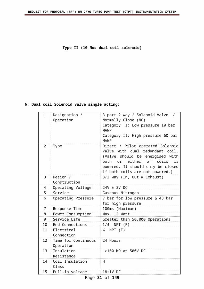
REQUEST FOR PROPOSAL (RFP) ON CRYO TURBO PUMP TEST (CTPT) INSTRUMENTATION SYSTEM
Sensor Elements has to be fixed by glass sealing with the depletion level sensor body.
Sensor Elements has to be isolated by the SS Sheet (Isolator) by spot welding method as given below.
Material Used:Body : SS321/SS304Electrode Pins : FERNI (Alloy 52)Isolator : SS304 Sheet.
Pre-delivery Inspection:Sample shall be provided for giving dispatch clearance by the department.
35.Weldable Vaccum feed through connector sets:Material
Housing : SS304Conductors : SS304 (gold plated)Insulator : Glass ceramicsTemperature range : -269 deg C to 450 deg CCurrent per pin : 5 A
Atmosphere side plug Insulator : Silicone rubber
Vaccum side plug Insulator : PEEK
Crimp contact pinMaterial : Copper Alloy (gold plated)
36. Level Electronics for Capacitance type discrete Level Sensor Array
The party shall carry out the fabrication of intrinsic safe electronics for LOX/LH2 discrete capacitance level sensors array as per diagrams given in
Page 81 of 117
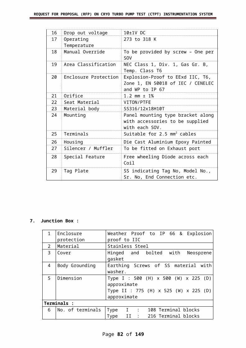
REQUEST FOR PROPOSAL (RFP) ON CRYO TURBO PUMP TEST (CTPT) INSTRUMENTATION SYSTEM
Annexure A. The electronics shall be mounted inside the explosion proof junction box suitable for EExid IIC application with suitable metallic cable gland. The intrinsically safe certification shall be obtained from CMRS, Dhanbad.
Specifications:The capacitance type discrete level sensor array is used to detect the
liquid level in the Cryogenic tanks.The capacitance level sensor array is located inside the Liquid
Oxygen/Hydrogen tanks by the department. These are 32 capacitance sensors in one level sensor array. The intrinsically safe electronics shall be placed near the tanks with enclosure suitable for group IIC (Hydrogen) environment. The line towards the capacitance level sensor is to be made intrinsically safe EExia IIC and certified by the certifying agency. Each sensor has to be connected with individual signal conditioner. The output of the individual signal conditioner shall be connected to microprocessor based CPU card to generate digital output. Parallel/redundant frequency generators are used as excitation source for all the sensors.
Fabrication of signal conditioner, intrinsically safe source (Frequency generator), CPU card and mother board for interconnecting all channels shall be carried out as per the diagram given in Annexure A. One set of Electronics contains the following:
Mother board : 1 NoPower supply card : 1 NoIntrinsically safe source : 1 No8 Channel signal conditioners : 4 NosCPU card : 1 NoEthernet output : Ethernet output port with fibre-optic
interface shall be provided in the digitizer card for enabling data transfer with remote computer.
Mechanical:Housing : The electronics shall be kept inside a
metallic enclosure. The whole assembly shall be kept inside the explosion proof metal hosing suitable for Hydrogen IIC environment with necessary explosion proof cable glands.
I/O Connector : Separate connector shall be provided for the following:
1. Sensors.2. Input power.3. Buffered analog O/P of all signal
conditioners.4. Isolated Digital outputs.5. Main/redundant function generators
Select command.6. Electronics test command.7. Fibre-optic Ethernet port
Page 82 of 117

REQUEST FOR PROPOSAL (RFP) ON CRYO TURBO PUMP TEST (CTPT) INSTRUMENTATION SYSTEM
Software specifications
Controller Software : Software for CPU shall acquire Analog output from all the 32 channels. The CPU also has to acquire multiplexed digital input and re-transmit the analog and digital data through Ethernet.
Display Software :Front-end software shall have the provision for online display, data logging and off-line data processing. The on-line display program shall clearly indicate the present status of level and corresponding analog input values. The data logging softaware shall log the data at the specified interval and duration.
Note:Detailed blocked diagram of Level Electronics, Circuit diagram of Level
Sensor Signal conditioner and CPU will be provided for fabrication.
37. Multi Cable Transit Blocks
The cable entry into Control Room and Signal Conditioning room shall be through Multi Cable Transit Blocks(MCT). The MCT’s (13 Nos of size 1000mm x 300mm) shall be supplied and installed at site by contractor. The required cutout sizes and frames sizes shall be finalized during detailed engineering.
The MCT frames shall be of Standard RGB type of Brattberg or Roxtex and of steel construction. The maximum height if frame shall not exceed 400mm. The MCT frames provided should be suitable to withstand blast intensity for which blast proof control room has been designed. The MCT shall be supplied complete with insert blocks, spare blocks, stay plates, end-packing etc.
Contractors shall size and provide MCT considering 50% spares for each cable size/cable OD.Contractor shall also provide 50%spare insert blocks in each cable size/O.D. as loose supply. Intrinsically safe cables for instruments(110V AC or above) shall be suitably separated from each other cables within theMCT frame and shall be routed through separate MCT blocks.
Page 83 of 117
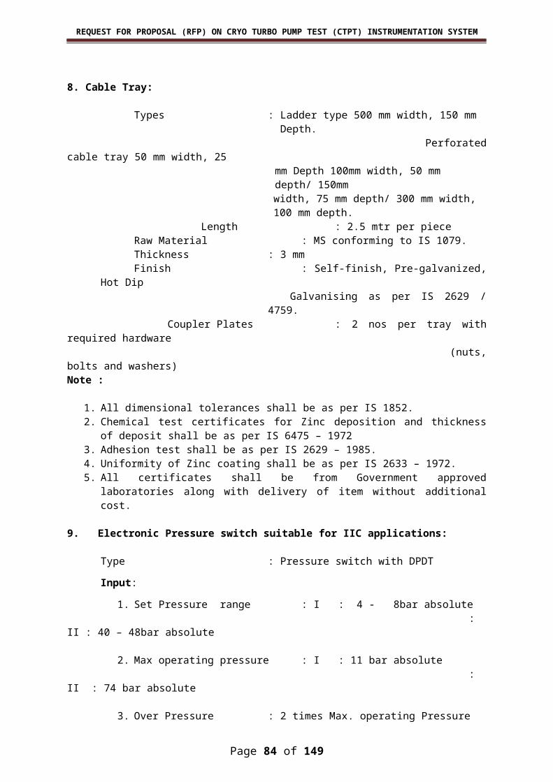
REQUEST FOR PROPOSAL (RFP) ON CRYO TURBO PUMP TEST (CTPT) INSTRUMENTATION SYSTEM
ANNEXURE- IV – CODES AND STANDARDS
Page 84 of 117

REQUEST FOR PROPOSAL (RFP) ON CRYO TURBO PUMP TEST (CTPT) INSTRUMENTATION SYSTEM
List of Applicable Codes and Standards
ANSI / ISA MC-96.1 : Temperature Measurement, Thermocouples
API RP-551 : Process Instrumentation & ControlASTM A-269 : Stainless Steel TubesIEC 751 : Industrial platinum resistance
thermometer sensors.IS 2148 : Flameproof Enclosures for Electrical
Apparatus (Second Revision - Amendment-2)
IS 5572, Part-I : Hazardous Area Classification for Electrical Installations
IS 5780 : Intrinsically Safe Electrical Apparatus and Circuits
NFPA 493 : Intrinsically Safe Apparatus in Div.I Hazardous Location
ANSI B16.5 : Pipe Flanges and Flanged FittingANSI B16.20 : Metallic Gasket for Pipe flanges, Ring-
joint, Spiral wound and SocketedANSI B1.20.1 : Pipe threads, General purpose (Inch)ISA S5.1 : Instrumentation Symbols and
IdentificationANSI/ISA–12.12.01–2000 : Nonincendive Electrical Equipment for use
in Class I and II, Div. 2 Hazardous (classified) locations.
Note: Other standards, norms and recommendations, if required, shall be suggested by the Vendor and get approved from Department.
Page 85 of 117

REQUEST FOR PROPOSAL (RFP) ON CRYO TURBO PUMP TEST (CTPT) INSTRUMENTATION SYSTEM
ANNEXURE- V – SUB-VENDOR LIST
Page 86 of 117

REQUEST FOR PROPOSAL (RFP) ON CRYO TURBO PUMP TEST (CTPT) INSTRUMENTATION SYSTEM
Sl. No.
Description Recommended Suppliers / Make
1. Pressure Switch 1. M/s. Switzer Process Instruments Pvt. Ltd.2. M/s. Honeywell Automation India Ltd.3. M/s. Omega 4. M/s SOR5. M/s GIC6. M/s Waaree7. M/s Pyroelectric
2. Solenoid valves 1. M/s ASCO, Chennai2. M/s Herion3. M/s Parkar4. M/s Rotex5. M/s Thomson
3. SOV Cubicle, Junction Box & Cable glands
1. M/s Baliga Lighting Equipments Ltd2. M/s FlameProof Equipments Pvt. Ltd3. M/s CEAG FlameProof Control Gears (P) Ltd4. M/s. Stahl, Chennai5. M/s FCG Power Industries Pvt. Ltd6. M/s ExProtecta7. M/S. P+F, Chennai
4. SS Tubes 1.M/S. Swagelok India2.M/s. Remi Engineering3.M/s Sandvik Asia Ltd, Maharashtra4.M/s Ratnamani Metals & Tubes, Gujarat5.M/s Rajendra Mechanical Industries, Mumbai6.M/s Choksi Tube Corporate Ltd , Ahmadabad
5. Tube fittings 1. M/s. Swagelok2. M/s. Parker
6. Cable Tray 1. M/s VSL Instruments2. M/s Elcon Instruments, Pune3. M/s Instrument Cable Trays4. M/s Sadhana Engg Corpn5. M/s Profab Engineers6. M/s Shruti Industries, Pune7. M/s Patney8. M/s JK Enterprises, Chennai
7. Terminal Block & Terminal Lugs
1. M/s Phoenix India 2. M/s.Wago
Page 87 of 117

REQUEST FOR PROPOSAL (RFP) ON CRYO TURBO PUMP TEST (CTPT) INSTRUMENTATION SYSTEM
Sl. No.
Description Recommended Suppliers / Make
3. M/s.Weidmullar4. M/s ABB
8. Instrumentation Racks
1. M/s Rittal
9. SMPS Power Sup-ply
1. M/s Phoenix2. M/s Lamda3. M/s Kepco
10. Push button switches, Key lock switches and Indicators
1. M/s Kaycee2. M/s Siemens3. M/s Alstom4. M/s L&T 5. M/s Schneider6. M/s ABB7. M/s GE8. M/s EAO Switchtc
11. Multi pin connec-tors
1. M/s Phoenix 2. M/s.Wago3. M/s.Weidmullar4. M/s Harting5. M/s Radial
12. Storage Rack 1. M/s Godrej13. Level Sensor 1. M/s CERA Seals, Bangalore
2. M/s Vistara Hermatics. Bangalore 14. Level electronics 1. M/s SYSTRACK, Bangalore15. Multicable Transit
Block1. M/s Roxtec2. M/s Brattberg
5.TERMS & CONDITIONS
Page 88 of 117

REQUEST FOR PROPOSAL (RFP) ON CRYO TURBO PUMP TEST (CTPT) INSTRUMENTATION SYSTEM
5.1 ENTIRE AGREEMENT
5.1.1 The Contract to be entered into shall convey the final agree-ment between the Department and the Vendor on the terms and condi-tions.
5.1.2 In the event of conflicts between general conditions of Con-tract and the specification furnished by the Department, the latter will take precedence.5.2 MODIFICATIONS IN THE CONTRACT
This Contract may be amended or modified only in writing signed by both the parties or their duly authorized agents or representatives by a change order issued by the Department and accepted by the Vendor, pursuant to the terms stated therein.
5.3 CANCELLATION OF CONTRACT5.3.1 The Department will have the right, at any time, to cancel the
Contract either wholly or in part by giving written notice. The Vendor shall undertake to observe the instructions of the Department as to the winding up of the Contract both on his own part and on the part of his sub-vendors.
5.3.2 In the case of cancellation of the Contract by the Department without any fault of the Vendor, the Vendor shall forthwith take the ne-cessary steps to implement the Department’s instructions. The period to be allowed to implement shall be fixed by the Department after con-sultation with Vendor and, in general, shall not exceed 3 months.
5.3.3 The ownership of all materials, part and unfinished work paid for by the Department under the provisions of this Section shall be ves-ted in or transferred to the Department as soon as they have been paid for.
5.4 VENDOR’S DEFAULT LIABILITY5.4.1 The Department shall reserve the right to terminate the work
in the circumstances detailed here under:a. If the Vendor fails to rectify or replace any defective system/ sub-system/ equipment within a period of 60 days after the Depart-ment having given a notice to the Vendor to rectify or replace the said defective system/ subsystem/ equipment or the Vendor delays, suspends or is unable to complete the system/ subsystem/ equip-ment by the date mutually agreed uponb. If the vendor commits breach of any of the terms and condi-tions of the Contract.c. If the Government of India decides to terminate the Contract in public interest.
Page 89 of 117
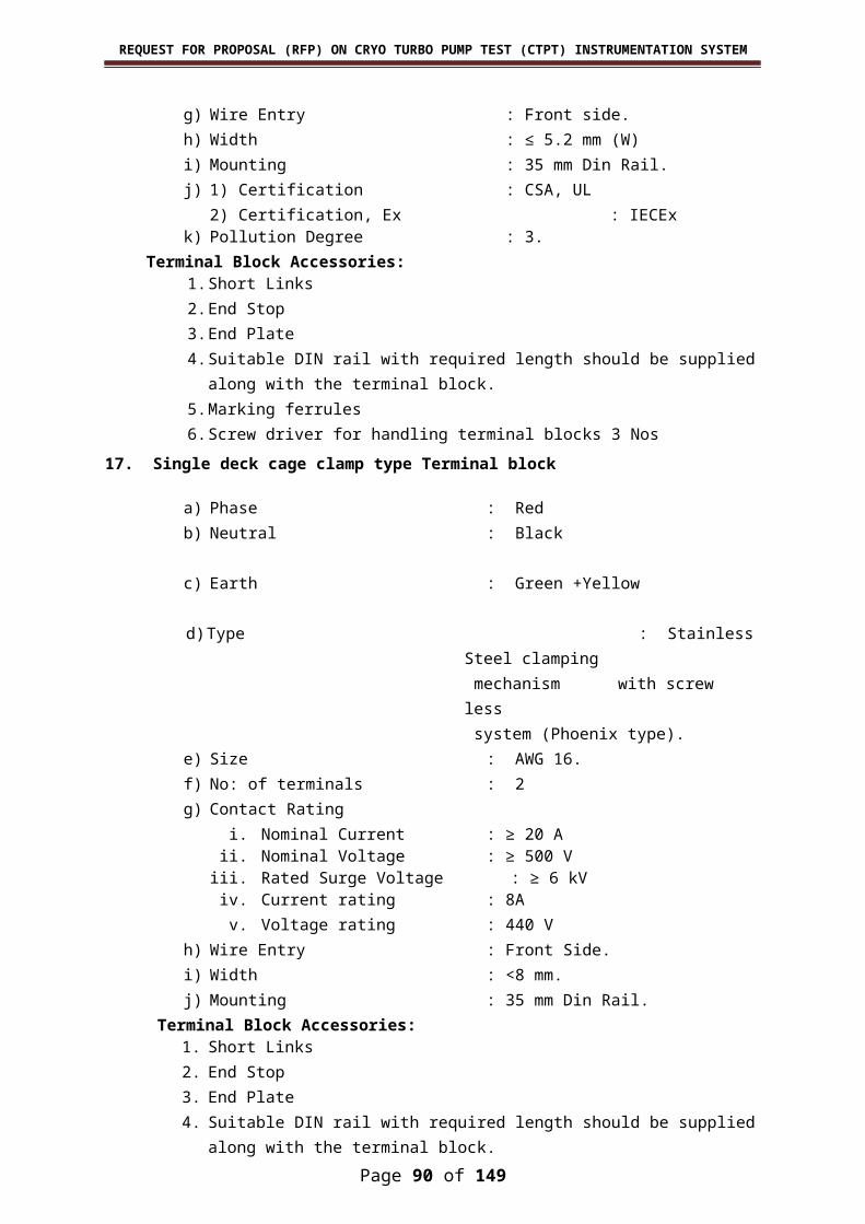
REQUEST FOR PROPOSAL (RFP) ON CRYO TURBO PUMP TEST (CTPT) INSTRUMENTATION SYSTEM
5.4.2 When the Vendor makes themselves liable for action under the circumstances mentioned above, the Department will have power to forfeit the bank guarantee of Vendor and the Vendor shall have no claim for damages whatsoever on such forfeiture.
5.4.3 If the supplier fails to complete the work as mentioned above in 5.4.1. a , b & c, the work shall be got executed through any other Vendor, in which case the expenses, which may be incurred in excess of sums, which would have been paid to the original Vendor, had the whole work been executed by them, shall be borne by the original Vendor and shall be recovered from them.
5.5 CHANGES AND MODIFICATIONS 5.5.1 The Department shall reserve the right at any time to modify
the requirements or drawings related to the work covered by the RFP.5.5.2 The Department may also accept the modification proposed
by the Vendor on his own initiative as a result of detailed engineering re-view.
5.5.3 The unit rates specified in the contract shall remain valid as long as the total price payable, for the actual quantity of work executed, is within ± 10 % of the total price mentioned in the contract.5.6 SUB-CONTRACTING
The Vendor shall not assign or sub-contract the work or any part of the work without the written approval of the Department. In the event of approval of sub-vendors, the detailed specifications and draw-ings of sub-contracted items shall be approved by the Department. All the works carried-out by such sub-vendors shall also be scrutinized, in-spected and approved by the Department. However the responsibility of such sub-contracted systems shall lie with the Vendor. Any delay in car-rying out the work by the sub-vendor which affects the overall schedule of the work does not absolve the Vendor from payment of compensation for the delays. All terms and conditions applicable to the Vendor shall also be applicable to sub-vendor.
5.7 COMPLIANCE WITH STANDARDSAll the materials supplied or used shall be of new and first
quality and manufactured and tested in accordance with the latest edi-tions of the relevant Indian/ International standards. Wherever imported components are used, they shall be manufactured in accordance with the relevant standards published in the country of manufacture after al-lowing for specific aspects under Indian conditions such as tropical cli-mate, etc. Any material or work, where no specific standard is applic-able, shall be fabricated as per the instructions and directions of the De-partment.
All the electrical equipments used shall conform to the latest Indian Elec-tricity rules as regards safety, earthing and other essential provisions specified therein for installation and operation of electrical parts.
Page 90 of 117
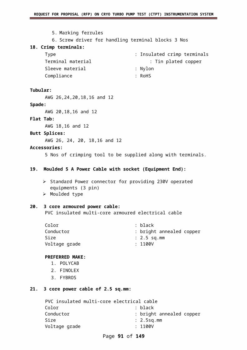
REQUEST FOR PROPOSAL (RFP) ON CRYO TURBO PUMP TEST (CTPT) INSTRUMENTATION SYSTEM
5.8 SECRECYThe technical information, drawings, specification and other
related documents forming part of enquiry or Contract are the property of the Department and shall not be used for any other purpose, except for execution of the Contract. All rights, including the rights in the event of grant of a patent and registration of designs are reserved. The tech-nical information, drawings, specifications, records and other documents shall not be copied, transcribed, traced or reproduced in any other form or otherwise in whole/part and/or duplicated, modified and/or disclosed to a third vendor and/or not misused in any other form whatsoever without the Department’s consent in writing except to the extent re-quired for the execution of the work. This technical information, draw-ings, specifications, records and other documents shall be returned to the Department with all approved copies and duplicates, if any, immedi-ately after they have been used for the agreed purpose.
5.9 INSPECTION OF WORK5.9.1 The Department or any person appointed by it shall have ac-
cess and right to inspect the work, or any part thereof, at all times and places during the progress of the work. The inspection and supervision is for the purposes of assuring the Department that the plans and specific-ations are being properly executed and while the Department and its representative(s) will extend to the Vendor all desired assistance in in-terpreting the plans and specifications, such assistance shall not relieve the Vendor of any responsibility for the work. Any work which is proved faulty shall be corrected by the Vendor without delay. The fact that faulty work or work which is not in accordance with plan and specifica-tions was not pointed out by the Department will not relieve the Vendor from correcting such work as directed by the Department without addi-tional compensation.
5.9.2 The Department’s representatives shall at all reasonable times have free access to the works and/ or to the workshops, factories or other places where materials are being prepared or fabricated for the work and also to any place where the materials are lying or from where they are being obtained, and the Vendor shall give every facility to the Department’s representatives for inspection and test of the materials and workmanship even to the extent of discontinuing portions of the work temporarily or of uncovering or taking down portions of finished work.
5.9.3 The Department has no obligations to discover defects pat-ents or otherwise and it shall be the sole responsibility of the Vendor. The inspection and clearance for dispatch by Department’s representat-ives shall not absolve the Vendor’s obligations and duties under terms and conditions herein.
Page 91 of 117
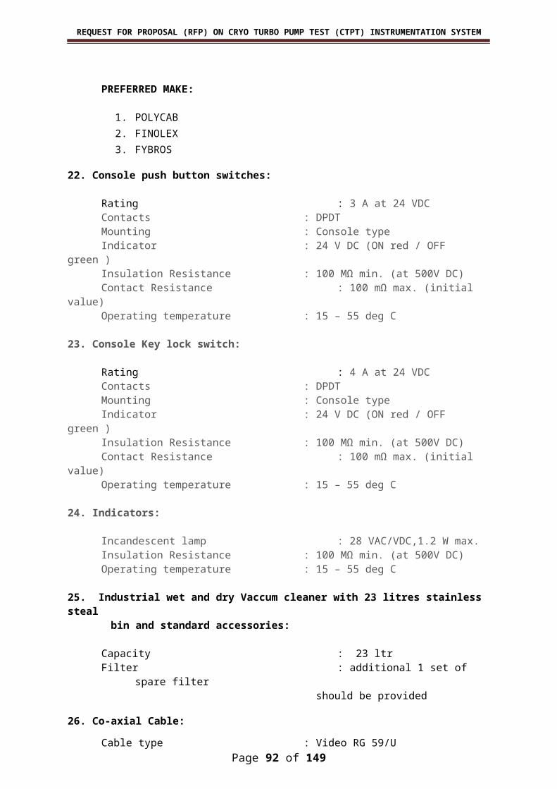
REQUEST FOR PROPOSAL (RFP) ON CRYO TURBO PUMP TEST (CTPT) INSTRUMENTATION SYSTEM
5.10 CO-ORDINATION WITH OTHER VENDORS AND INTERFACING OF THE WORKS
The Vendor shall extend all co-operations to other Vendors of the Department to perform their works at site simultaneously. The Vendor shall so arrange their activities so as to ensure smooth and timely execution of the project minimize interference with the works of the other Vendors and allow the other Vendors to use the facilities engaged by them for erection activities. For this purpose, the Vendor shall plan such works and indicate such interfaces in an interface schedule. They shall not be entitled to any extra payment on this account.
5.11 FORCE MAJEUREIf at any time during the execution of the Contract, the per-
formance in whole or in part by either vendor of any obligation under the work is prevented or delayed by reasons of any war, hostility, acts of the public enemy/terrorist, civil commotion, sabotage, fire, flood, earth quake, epidemics, quarantine restrictions, strikes, lock-outs, or acts of God (hereinafter referred as Eventualities) and if notice is given by either vendor to the other within 21 days from the date of occurrence thereof, neither vendor shall for such eventuality be entitled to terminate the work nor shall any vendor have any claim for damages against the other in respect of such non-performance or delay in performance. The per-formance under the work shall be resumed as soon as practicable after such eventualities have come to an end and the decision of the Depart-ment whether the performance has been resumed or not shall be final and conclusive.
Provided further that if the performance in whole or in part of any obliga-tion under the work is prevented or delayed by such eventuality for a period of exceeding 60 days, the Department may at their option termin-ate the Contract provided also if the work is terminated under this clause, the Department will be at liberty to take over from the Vendor at a price fixed by the Department which shall be final. All unused, un-dam-aged acceptable materials, bought-out components lying in stores in course of erection and commissioning in the possession of the Vendor at the time of such termination of such portion thereof as the Department may deem fit excepting such material, bought-out components lying in stores as the Vendor may with the concurrence of the Department elect to retain.
5.12 INDEMNITY TO DEPARTMENT AGAINST INFRINGEMENT OF LABOUR LAWS
The Vendor shall indemnify the Department against any ac-tion, claim or proceedings relating to infringement of all or any of the prevailing labour laws of India like Workmen’s Compensation Act 1923, Work Labour (Regulation and Abolition), Central Rules 1971, Employees Liability Act 1938, Industrial Disputes Act 1947, Employees Provident
Page 92 of 117

REQUEST FOR PROPOSAL (RFP) ON CRYO TURBO PUMP TEST (CTPT) INSTRUMENTATION SYSTEM
Funds and Miscellaneous Act 1952 as amended from time to time during erection and commissioning at Department’s site.
5.13 PATENT RIGHTSThe Vendor shall fully indemnify the Department against any
action, claim or proceedings relating to infringements or use of any pat-ent or any design or any alleged patent or design rights and shall pay any royalty which may be payable in respect of any claims made under or any action brought against the Department. In respect of such mat-ters as aforesaid, the Vendor shall be set at liberty, at their own ex-pense, to settle any dispute or to conduct any litigation that may arise there-from. The Vendor shall not be liable to indemnify the Department on the infringement of the patent or design or any alleged patent or design right which is the direct result of an order passed by the Depart-ment.
5.14 ARBITRATIONExcept matters in respect of which the decision of the De-
partment is final as specified in the Contract, any dispute, disagreement or question arising out of or relating to or in consequence of the work or fulfilment or the validity of the enforcement thereof which cannot be settled mutually, shall within 30 days from the date that either vendor in-forms the other in writing that such dispute or disagreement exists, be referred to arbitration. The Arbitrator shall be a serving Law officer of the rank of Joint Secretary to the Government of India and shall be nomi-nated by Director, IPRC. The award of the Arbitrator so appointed shall be final and binding on the parties to this Purchase Order. The arbitration proceedings shall be in compliance with the Arbitration and Conciliation Act 1996. The performance under this work shall continue during the ar-bitration proceedings and no payment due or payable by the Department will be withheld unless any such payment is or forms part of the subject matter of the arbitration proceedings. All expenditures towards arbitra-tion will be equally shared by both the parties
5.15 ASSIGNMENTThe work shall be binding upon the successors and the as-
signees of the parties hereto. It shall not be assigned in whole or in part by either vendor without prior written consent of the other. If the Vendor becomes insolvent or being a firm or a company whether incorporated or not is dissolved or goes into bankruptcy or is caused to be wound up ex-cept for re-construction purposes or carried on its business under a re-ceiver, the representatives in law of estate of the Vendor or any such re-ceiver, liquidator or any person in whom the agreement may be vested shall forthwith give notice thereof in writing to the Department and shall remain liable for the successful performance of the Vendor or the suc-cessors of their obligations under this Contract under any circumstances.
5.16 JURISDICTION AND APPLICABLE LAW
Page 93 of 117

REQUEST FOR PROPOSAL (RFP) ON CRYO TURBO PUMP TEST (CTPT) INSTRUMENTATION SYSTEM
The work shall be governed by the laws of India for the time being in the force. The courts of Tamil Nadu State only shall have juris-diction to deal with and decide any legal matters or dispute whatsoever arising out of the work.
5.17 EXECUTION OF WORKThe specifications of the work are intended to describe and
provide for a complete finished system. It is to be understood and agreed by the Vendor that the work described shall be completed in every detail, even though every item necessarily involved is not particu-larly mentioned. The Vendor shall be required to provide all labour, ma-terials and equipments necessary for the completion of the work de-scribed and shall not avail themselves of any manifesting unintentional error, omission or inconsistency that may exist. The Vendor shall carry out and complete the work in every respect in accordance with the Con-tract and the directions and to the satisfaction of the Department.
5.18 RIGHTS OF THE DEPARTMENT5.18.1 RIGHT TO ILLUSTRATE AND EXPLAIN PLANS
a. The various parts of the Contract are intended to be comple-mentary to each other but if any discrepancies appear or any misunder-standing arises, the explanation of the Department will be final and bind-ing.
b. The corrections of any errors or omissions of specifications may be made by the Department, when such correction is necessary to bring out clearly the intention which is indicated by a reasonable inter-pretation of the specifications as a whole.
c. Wherever in the specifications which are a part of the work or which may be furnished to the Vendor for directing the work, the terms and descriptions of various qualities of workmanship, materials, struc-tures, processes, plant or other features of the work are described in gen-eral terms, the meaning of fulfilment of which must depend upon indi-vidual judgments, then in all such cases, the question shall be decided by the Department and said material shall be furnished, said work shall be done and said structure or feature shall be constructed, furnished or car-ried out in full and in accordance with their interpretation of the same and to their full satisfaction and approval, provided such interpretation is not in direct conflict with the specifications or generally accepted good practice.
5.18.2 RIGHT TO DIRECT WORK
a. The Department will have the right to direct the manner in which all work under this Contract shall be done, in so far as it may be necessary to secure the safe and proper progress and the specified quality of the work and all work shall be done and all material shall be furnished to the satisfaction and approval of the Department.
Page 94 of 117
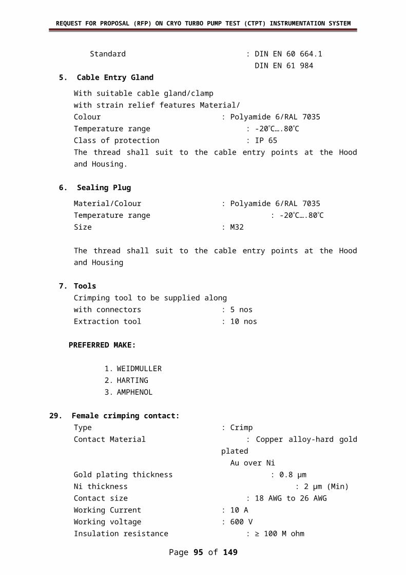
REQUEST FOR PROPOSAL (RFP) ON CRYO TURBO PUMP TEST (CTPT) INSTRUMENTATION SYSTEM
b. Whenever, in the opinion of the Department, the Vendor has made marked departure from the schedule of completion laid down in the Contract or when untoward circumstances force departure from the said schedule, the Department in order to assure compliance with the schedule and the provisions of the work, shall direct the order, pace and method of doing the work, which shall be adhered to by the Vendor.
c. If, in the judgment of the Department, it becomes necessary at any time to accelerate the overall execution of the work, the Vendor when ordered and directed by the Department will cease the work at any particular point and transfer their men to such other point or points and execute such portion of their works, as may be required, to enable others to hasten and properly engage and carry on their work, as direc-ted by the Department.
d. The work by the Vendor at the site beyond normal working hours (08:45 to 17:15 hr) on working days and any time on holidays (in-cluding Saturdays and Sundays) shall be permitted only with prior ap-proval of the Department. The Department may also direct the Vendor to operate extra shifts over and above normal day shift to ensure com-pletion of the work on schedule if, in the opinion of the Department, such work is required.
5.19 VENDOR’S FUNCTIONS5.19.1 The Vendor shall provide everything necessary for proper ex-
ecution of the work according to the intent and meaning of the specifica-tions whether the same may or may not be particularly shown or de-scribed therein, provided that the same can reasonably be inferred there-from and if the Vendor finds any discrepancy there-in, they shall immedi-ately and in writing refer the same to the Department whose decision shall be final and binding on the Vendor.
5.19.2 In the execution of the work, no person other than the Vendor, or their duly appointed representatives, their sub-vendors, and their workmen, shall be allowed to work at the site except by special per-mission, in writing by the Department.
5.19.3 The Vendor shall proceed with the work to be performed un-der this Contract and each and every part and detail thereof, in the best and most workmen-like manner by engaging qualified, careful and effi-cient workers and to the several parts thereof at such time and in such order as the Department directs and finish such work in strict conform-ance with the drawings and/or specifications and any changes, modifica-tions thereof made by the Department.
5.19.4 The Vendor’s personnel shall not be permitted to reside in-side the Department’s premises after the work. The Vendor shall arrange for transportation, accommodation, food, health care, communication, in-surance etc. for their personnel.
5.19.5 In respect of observance of local rules, administrative orders, working hours and the like, the Vendor and their personnel shall co-oper-ate with the Department.
Page 95 of 117

REQUEST FOR PROPOSAL (RFP) ON CRYO TURBO PUMP TEST (CTPT) INSTRUMENTATION SYSTEM
5.20 SUPPLY OF TOOLS, AND OTHER MATERIALS 5.20.1 For full completion of the work, the vendor shall, at their own
expense, furnish all erection tools, power tools, cables, wiring tools, test instruments, and all associated protective equipments, appliances, ma-terials required to accomplish the work under the contract unless other-wise provided for. Adequacy of such tools shall be subject to final de-termination of the Department.
5.20.2 The vendor shall not dispose, transport or withdraw any tools, equipments and materials provided by them for the contract without tak-ing prior written approval from the Department and the Department at all times shall have right to refuse permission for disposal, transport or withdrawal of tools, equipment and material if in their opinion, the same will adversely affect the efficient completion of the work.
5.20.3 The vendor shall also furnish all necessary expendables tools, soldering iron (with lead and flux), tube bender, hacksaw blades, insula-tion tapes, harnessing materials, cable ties, anabond, Teflon tapes, nuts & bolts, clamps, ferrules, Polymide glands, terminal blocks, end termin-als, shrinkable sleeves and all other miscellaneous items required for in-strumentation erection and rack wiring.
5.21 PROTECTION OF WORK5.21.1 The Department will not be responsible or held liable for any
damage to person or property consequent upon the use, misuse or fail-ure of any fabrication tools and equipment used by the Vendor or any of their sub-vendors.
5.21.2 The Vendor shall effectively protect all the works from action of weather and from damages or defacement and shall cover finished parts where required for their thorough protection.
5.21.3 The Vendor is sole responsible for any damage incurred to any IPRC property.
5.22 SITE PERSONNELThe vendor shall identify a Site Supervisor and he/ she shall
be personally present to supervise the work under the contract. The Site Supervisor shall have full technical capability and complete administrat-ive and financial powers to expeditiously and efficiently execute the work under the contract. Any written orders or instructions which the De-partment may give to the vendor’s Site Supervisor shall be deemed to have been given to the vendor.
5.23 FIRST AIDThe Vendor may have access to the Departments’ qualified
first aid personnel and ambulance in case of accidents, subject to the availability of the same. However, the Vendor shall make his own med-ical and transport arrangements to take care of his employees in case of
Page 96 of 117

REQUEST FOR PROPOSAL (RFP) ON CRYO TURBO PUMP TEST (CTPT) INSTRUMENTATION SYSTEM
accident. The Vendor shall provide a first aid kit at the work site to meet the requirements of minor injuries.
5.24 REPORTINGThe Vendor must report the following information to the De-
partment by the end of every week during the work at Department’s site.
a) Progress achieved
b) Expected dates for completion of individual works
c) Any actual or likely delay in the execution of work
5.25 WORKING AND SAFETY REGULATIONSThe Vendor shall observe all statutory and legal requirements
enforced by Central and State Government applicable to the work as well as any local regulations applying to the site issued by Department or any other authority. Particular attention is drawn to the following;
a) In case of accident, the Department shall be informed in writing immediately. The Vendor shall strictly follow the regulations laid down by the Factory Inspector, Central and State Government authorities in this regard.
b) Compliance with all electricity regulations.
5.26 ELECTRICAL SAFETY REGULATIONSIn no circumstances will the Vendor interfere with fuses and
electrical equipment belonging to the Department or other Vendors. Be-fore the Vendor connects any electrical appliance to any plug or socket belonging to other Vendor or Department, he will
a) Satisfy Department that the appliances are in good working condition
b) Inform the Department of the maximum current rating, voltage and phase of the appliance
c) Obtain permission of the Department detailing the sockets, to which the appliance may be connected
5.27 POWERElectricity will be supplied at free of cost. Vendor must
provide power supply distributor with isolator for taking power for his equipments. Vendor should obtain Electrical safety clearance from CMG/IPRC and safety clearance from safety division before starting the work.
5.28 WATERFree supply of water will be made available by the Depart-
ment.
Page 97 of 117
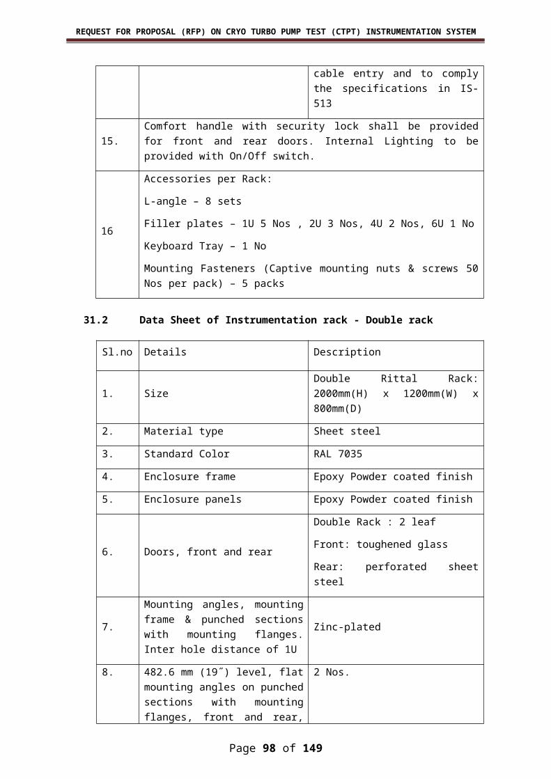
REQUEST FOR PROPOSAL (RFP) ON CRYO TURBO PUMP TEST (CTPT) INSTRUMENTATION SYSTEM
5.29 CLEAN-UP OF WORK SITEThe vendor shall not store or place the equipment, materials
or erection equipment on the drive ways and streets and shall take care that their work in no way restricts or impedes traffic or passage of men and material. All waste materials are to be disposed off safely to the loc-ation specified by the department
5.30 SAFETY AND RELIABILITY Since the systems are highly complex in nature, the philo-
sophy and criteria to be adopted shall be highly safety-and-reliability-ori-ented for their systematic and proper functioning. Reliability is a prime factor, which has to be embedded in the process of realization of the sys-tems. To ensure that the sub-system erection, development, selection of equipment, components, material, etc are in compliance with the stand-ard engineering practices, it is necessary to follow established instru-mentation standards.
5.31 SECURITY DEPOSITThe Supplier shall deposit an interest free amount equivalent
to the 10% (TEN PERCENT) of the total order value towards Security De-posit for the due performance of the Purchase Order within 30 days from the date of Purchase Order/ Contract. The Security Deposit can be sub-mitted either in the form of (a) Demand Draft drawn in favour of Ac-counts Officer, IPRC, (b) Bank Guarantee in Rs.100/- Non-judicial Stamp Paper obtained from any Nationalized/Scheduled Bank and (c) Term De-posit Receipts duly endorsed by the respective Banks in favour of IPRC. This security deposit shall be returned to the Supplier only upon success-ful completion of all the contractual obligations or shall be adjusted / for-feited against non-fulfilment of any of the contractual obligations.
An Indemnity Bond is to be provided by Central PSUs/PSEs/Autonomous Bodies/MSEs as a Security Deposit.
5.32 QUALITY ASSURANCEThe reliability of Instrumentation is a combination of specific-
ation of the equipments/ components, serviceability and maintenance of the same, which are meant to serve and provide effective and timely op-eration, which includes trouble-free performance of systems and sub-systems to the intended specifications.
The Vendor must look for the quality factors individually at-tributed to engineering developments, selection of equipments and com-ponents, test and acceptance procedures followed, repetitive perform-ance achieved, etc. each and every module must be manufactured and tested to international Quality Control standards. The test certificates shall be provided to Department.
The quality assurance is an unified approach that attempts to control the quality right from design stage to commissioning stage, which includes the checking of the adequacy of the equipments/ com-ponents for materials, fabrication, installation, testing. It is the com-bined responsibility of the Vendor and the Department to ensure that all
Page 98 of 117

REQUEST FOR PROPOSAL (RFP) ON CRYO TURBO PUMP TEST (CTPT) INSTRUMENTATION SYSTEM
possible failure modes are exercised and validated during erection and commissioning
5.33 PURCHASE OF MATERIALSThe selection of equipments, components, materials, etc.
with appropriate and suitable specifications shall be the responsibility of the Vendor, as overall performance of the system rests with the Vendor. Accordingly, the selection and purchase tasks shall be handled by the Vendor immediately after the approval of Detailed Engineering docu-ments by the Department.
The criteria for selection of particular product and the reasoning involved therein shall be submitted to the Department for necessary approval. However Department’s decision will be final.
For the goods of foreign origin, if any, the Supplier/their Supplier shall ar-range Export License.
The Department will provide necessary end-use certificate for obtaining the required license for import of items if requested by the Contactor.
In keeping with the terms of the Contract, the Vendor shall undertake the responsibility for handling, packaging and transportation involved to the accepted level of any sub-systems/ equipment covered by the work in the Contract.
5.34 EMPLOYMENT OF LABOURS The vendor shall deploy Indian National only for execution of the
work.
Only skilled employees with experience of this particular work shall be employed.
No person below the age of 18 years shall be employed.
The Supplier shall pay to each person, wages not less than those specified by Minimum Wages Act.
The employees / labour, for carrying out all the site works shall be identified well in advance by the vendor and necessary approval shall be obtained from the Department for entry permit to the work site.
5.35 GATE PASSFor Vendor’s equipment, tools, materials, etc. which are to be
taken out from IPRC, Mahendragiri campus after completion of work, proper entry shall be made at the main gate duly endorsed by CISF. The Department shall issue necessary gate passes for taking out the Vendor’s materials, as and when required and after completion of work.
Page 99 of 117
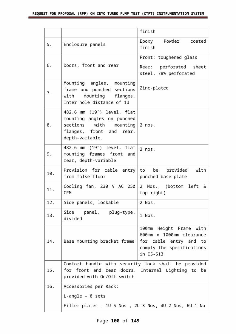
REQUEST FOR PROPOSAL (RFP) ON CRYO TURBO PUMP TEST (CTPT) INSTRUMENTATION SYSTEM
6. INSTRUCTIONS TO BIDDERS
The quotations are invited on behalf of the President of India by the Head, Purchase & Stores, IPRC, Mahendragiri, from reputed Vendors of high competence for the following work for IPRC, Mahendrag-iri, Tirunelveli District, Tamil Nadu State, India.
6.1. SCOPE OF WORKThe scope of the work includes Detailed Engineering, Pro-
curement, erection & commissioning , test & Evaluation and documenta-tion for Cryo Turbo Pump Facility as per the specification given in this document. The bidder is required to submit quotation for the entire works mentioned herein. The incomplete quotations shall be summarily rejected. The deviation, if any, in the bidder’s proposal with respect to this document shall be explicitly mentioned in the schedule of deviations to be provided in the quotation. If the bidder does not mention any devi-ation, it shall be construed by the Department that the bidder agrees to comply with each and every aspect of this document.
6.2 EXECUTION PERIODThe proposed work contract is to cater to the requirements of
procurement, installation and commissioning of instrumentation system for Cryo Turbo Pump Test Facility at IPRC, Mahendragiri. The contract shall be valid for a period of 15 months from the date of award of con-tract. The execution schedule shall be as given below.
Sl. No Scope of work Period Responsibility1 Detailed engineering and
acceptance by Depart-ment
1.5 months Vendor
2 Supply of Materials 4.5 months (from the date of approval of detailed engin-
eering)
Vendor
3 Rack wiring 8 months4 Field Erection and com-
missioning 7 months Vendor
5 Test and Evaluation 2 months Vendor6 Site Acceptance trials 1 month Vendor
6.3 Liquidated Damages
Page 100 of 117

REQUEST FOR PROPOSAL (RFP) ON CRYO TURBO PUMP TEST (CTPT) INSTRUMENTATION SYSTEM
If the vendor fails to complete execution of the contract or fails to meet delivery specified in the contract or any extension thereof, the Department will recover from the Vendor as Liquidated Damages (LD) a sum of 0.5% of the total contract price for each calendar week of delay. The total liquidated damages shall not exceed 10% of the con-tract value.
7. DELIVERY TERMAll equipments/materials to be supplied by vendor shall be de-
livered at IPRC, Mahendragiri. The vendor shall be responsible for further transportation of items to erection site. Further responsibility of handling and storage of all items lies with the vendor. Despatch clearance is to be ob-tained from the department by submitting necessary test certificate for sup-ply portion.
8. LANGUAGES AND MEASURES All documents pertaining to the Contract including specifications,
schedules, notices, correspondence, operating and maintenance instructions, drawings or any other writings shall be written in ENGLISH Language only.
9. DOCUMENTS All operating, maintenance and technical manuals, drawings and
diagrams in English Language relevant to the systems/components shall be supplied by the Vendor.
10. GUARANTEEa) The “Defect Liability Period” shall be 12 months from the date of suc-
cessful completion of commissioning of instrumentation system. The work shall not be considered as completed until the Department has certified in writing that they have been actually accepted and the De-fect liability period shall commence from the date of such certificate.
b) The equipments & material supplied by the vendor shall carry a guar-antee for a period of 12 months from the date of commissioning, against any material defect, design defect, manufacturing defect and/or failure of equipment to perform, as stipulated.
c) In case any defect in the work due to bad materials, and/ or bad work-manship develop in the work before the expiry of the period, the Vendor, on notification by the Department, shall rectify or remedy the defects at their own cost and shall make their own arrangements to provide materials, labour, equipment and any other appliances re-quired in this regard.
d) The equipments, or components repaired or replaced by the Vendor shall be guaranteed for a period of 12 months from the date of repairs or replacement.
e) The Vendor shall furnish performance guarantee in the form of an un-conditional irrevocable bank guarantee to the extent of 10 % of the
Page 101 of 117

REQUEST FOR PROPOSAL (RFP) ON CRYO TURBO PUMP TEST (CTPT) INSTRUMENTATION SYSTEM
total contract value valid for 60 days beyond warranty period. If any defect is noticed by the Department during the warranty period and Vendor fails to rectify or remedy the defects, the Department will have the right to get this done by other agencies and recover the cost in-curred, as determined by the Department, which shall be final and binding, by recovery from the amounts due to the Vendor and/ or by enforcing bank guarantee.
11. INSURANCEInsurance is not required at Department cost. However, the
vendor should take all necessary steps for safe delivery of items at pur-chaser’s site.
12. PACKINGThe vendor shall pack all the equipments, materials and its
accessories and make the identification names at the top of each pack. Proper packing shall be done so as to ensure that the items are not dam-aged during transportation.
13. FORM OF QUOTATIONThe quotation shall be submitted in two parts as follows: a. Technical and commercial b. Price c. The first shall contain the technical and commercial aspects shall be
opened first. The price quotation and the revision in prices thereof if any submitted subsequently based on authorization from the Department, shall be opened only after the evaluation of the technical and commercial quotation. Technical and commercial offer shall not contain any price.
The Department reserves the right to reject any or all quotations in whole or part without assigning reasons thereof.
14. PRICESThe bidder shall quote firm and fixed prices valid during the exe-
cution of the Contract till commissioning and site acceptance of the sys-tems to the satisfaction of the Department. The prices shall include all taxes. We are exempted from payment of excise duty, customs duty, oc-troi etc.
The bidder shall provide the individual item wise break-up prices as given in Annexure-B price format.
15. PAYMENTMilestone payments: Milestone payment will be considered as follows:
• For supply of Instrumentation Items and Field Erection materials
Page 102 of 117
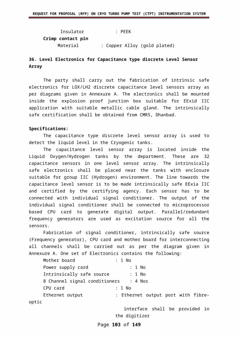
REQUEST FOR PROPOSAL (RFP) ON CRYO TURBO PUMP TEST (CTPT) INSTRUMENTATION SYSTEM
– 90% of supply price shall be released within 30 days against receipt and acceptance of item at IPRC, Mahendragiri.
• For Detailed Engineering, Installation, Erection & Commissioning of field, SCR and control room instrumentation, Rack assembly, mounting of equipments electrical wiring & Termination – 90% of Detailed Engineering, Installation, Erection & Commissioning of
field, SCR and control room instrumentation, Rack assembly, mounting of equipments electrical wiring & Termination price, shall be released on pro rata basis for the completed works.
Balance 10% payment
– Balance 10% of supply portion shall be released after acceptance of test and evaluation.
– Balance 10% of Detailed Engineering, Installation, Erection & Com-missioning of field, SCR and control room instrumentation, Rack as-sembly, mounting of equipments electrical wiring & Termination price shall be released after acceptance of test and evaluation commis-sioning checks as per 3.4.5.2.2.
Performance Bank Guarantee– PBG at 10% of the value of the total Purchase Order will be obtained
through bank guarantee from any of the Scheduled Banks executed on non judicial stamp paper of appropriate value, and will be valid for a period of sixty days beyond the date for completion of all the terms and conditions of the Purchase Order/expiry date of warranty period
– An Indemnity Bond is to be provided by Central PSUs/PSEs/Autonom-ous Bodies/MSEs as PBG.
16. VALIDITY The quoted price should be valid for a period of 6 months from
the date of opening of the technical and commercial quotation.17. QUANTITY VARIATION OF ITEM
The exact quantity and the list of items required for commis-sioning the facility will be finalized during detailed engineering and 10% quantity variation shall be permitted for supply and erection part of con-tract.
18. PRE-BID MEETING Within 2 weeks from date of floating of tender, it is proposed to
brief all interested bidders on the requirements of this document at IPRC, Mahendragiri and the exact date will be intimated after tendering. Bidders interested to participate in the pre-bid meeting shall communicate their willingness in writing to Head, Purchase & Stores immediately on receipt of this document.
Page 103 of 117

REQUEST FOR PROPOSAL (RFP) ON CRYO TURBO PUMP TEST (CTPT) INSTRUMENTATION SYSTEM
The offers from bidders not participating in the pre-bid meeting will not be considered for technical and price bid evaluation.
19. BIDDER’S PROFILE The bidder shall elaborately bring out in their techno commercial
offer, their company profile, which shall be commensurate with the level demanded for the execution of the work specified in this document. De-partment has right to reject the proposals which are in-complete or found unsuitable based on the details requested below.
The details shall include the following
a. Infra-structural facilities, machineries, equipments, material han-dling devices, instruments, tools, tackles, etc
b. Human resource inventory under the categories such as execu-tives, managers, engineers, supervisors, foremen, technicians, unskilled laborers, clerical staff, auxiliary staff, etc. The educa-tional qualification, expertise and experience of the key staff shall also be submitted.
c. Financial soundness, specifying the annual turn-over, annual in-come tax paid, name of the banker, etc.
d. Previous experience in the execution of projects of the nature and quantum on par with those specified in this document.
e. Experience of having successfully completed similar works as mentioned below during last 7 years ending 30th September 2016 shall be submitted.One project costing more than Rs. 80.00 lakhs
(or)Two projects costing more than Rs. 60.00 lakhs each
(or)Three projects costing more than Rs. 40.00 lakhs each.
f. Clientele, specifying the clients to whom they have executed works of nature similar to that specified in this document. The address, telephone, fax, E-mail and contact person of the clients shall also be specified.
Page 104 of 117

REQUEST FOR PROPOSAL (RFP) ON CRYO TURBO PUMP TEST (CTPT) INSTRUMENTATION SYSTEM
ANNEXURE- VI – PRICE FORMAT
CTPT Price FormatPage 105 of 117

REQUEST FOR PROPOSAL (RFP) ON CRYO TURBO PUMP TEST (CTPT) INSTRUMENTATION SYSTEM
Sl. No Description
Pro-posed
QtyUnit
Unit Rate
in INRTotal in INR
A.
Supply of Instrumentation Items and Field Erection Ma-terial:
1SS 304L Seamless Tubes as per ASTM A269 with 12 mm OD 2 mm thick SS tube for 450 bar working pressure (Length of 6 mtrs)
1200 mtrs
2SS 304L Seamless Tubes as per ASTM A269 with 8 mm OD 1.5 mm thick SS tube for 50 bar work-ing pressure (Length of 6 mtrs)
2000 mtrs
3Structural steel Materials (MS Flat, Angles, Channels, Bolts, Screws, Nuts, washers and clamps)
10000 kg
4Aluminium Cable gland for 2 Core 18/20AWG with 14mm OD Ar-moured Cable (1/2”)
1700 Nos
5Aluminium Cable gland for 2 Core 12AWG/4 Core 20AWG with 16-18mm OD Armoured Cable (3/4”)
1200 Nos
6Aluminium Cable gland for 10 Core 18AWG with 24mm DD Ar-moured Cable (1")
100 Nos
7Aluminium Cable gland for 20 Core 18AWG with 30mm OD Ar-moured Cable (1 1/4 ”)
300 Nos
8Aluminium Cable gland for 40 Core 12AWG with 40mm OD Ar-moured Cable (1 1/2”)
50 Nos
9Aluminium Cable gland for 80 Core 18AWG / 96 Core 20AWG with 48mm OD Armoured Cable (2”)
200 Nos
10 Aluminium plug (½” , 3/4", 1", 1 1/2", 2" NPT) 350 Nos.
11
Supply of Cubicle with 5 Nos High Pressure Dual coil Solenoid valve (48 bar) Explosion Proof to Eexd IIC enclosure protection , Explo-sion proof Junction box(Independ-ent Main & Redundant with min 15 terminals in each Junction box)
4 Sets
12
Supply of Cubicle with 10 Nos Low pressure Dual coil Solenoid valve (8 bar) Explosion Proof to Eexd IIC enclosure protection, Explosion proof Junction box(Independent Main & Redundant with 25 ter-minals in each Junction box)
22 Sets
13Junction Box 500 x 500 x 225 mm size including 108 electrical ter-minal blocks
20 Nos
14Junction Box 775 x 525 x 225 mm size including 225 electrical ter-minal blocks
18 Nos
Page 106 of 117

REQUEST FOR PROPOSAL (RFP) ON CRYO TURBO PUMP TEST (CTPT) INSTRUMENTATION SYSTEM
15
500 mm Ladder type cable tray(Width:500mm, Height: 100mm, Thickness: 2.5mm) with coupler plates and fixing hard-ware (bolts and nuts)
1500 mtrs
16
50 mm Perforated type cable tray(width: 50mm, Height: 25mm, Thickness: 2.0mm) with coupler plates and fixing hardware (bolts and nuts)
2000 mtrs
17
100 mm Perforated type cable tray(width: 100mm, Height: 50mm, Thickness: 2.0 mm) with coupler plates and fixing hard-ware (bolts and nuts)
700 mtrs
18
150 mm Perforated type cable tray (width: 150 mm, Height: 50 mm, Thickness: 2.0 mm) with coupler plates and fixing hard-ware (bolts and nuts)
500 mtrs
19
300 mm Perforated type cable tray(width: 300mm, Height: 50mm, Thickness: 2.0 mm) with coupler plates and fixing hard-ware (bolts and nuts)
250 mtrs
20 Electronic Pressure Switch suit-able for IIC applications 38 Nos
21
Powder coated Canopy for roof (MS sheet of Thickness 2 mm and width varying from 500 to 750 mm suitable for Junction boxes, Pressure / Temperature transmit-ters and Cubicles)
175 Sq.m
22
Powder coated MS sheet of Thick-ness 2 mm and width varying from 600 to 1200 mm suitable for mounting DIN Rail, PVC Cable duct and connectors in instru-mentation rack
40 Sq.m
23Multicable Transit block with frames, sealing module, stay plate and weges for cable entry of size 1000mm x 300mm
13 sets
24 Supply of 2” GI Pipe 200 Mtrs
25Hermatically Sealed Electro Mag-netic DPDT Relays with socket LED indication and DIN rail Mount-ing Accessories
1500 Nos
26
Din Rail Mountable SMPS 24 V / 20 A with Oring Module ( Each Set with Main power supply 1 No, Re-dundant power supply 1 No and Diode Oring Module 1 No)
50 Sets
27 Contactor relay 20 Nos
28Hall Effect Sensor for 3 A, 10 A, and 20 A Current Measurement with Mounting PCB
200 Nos
Page 107 of 117

REQUEST FOR PROPOSAL (RFP) ON CRYO TURBO PUMP TEST (CTPT) INSTRUMENTATION SYSTEM
29
Double deck dual clamp on Ter-minal Blocks with dual diode for terminating AWG 18 and 12 wires ( Phoenix Grey colour) with end clamp, marking ferrules & end stop
1500 Nos
30
Dual Deck Cage Clamp Type Ter-minal Blocks for terminating AWG 26, 24, 20, 18, 12(Phoenix) with end clamp, marking ferrules & end stop
9000 Nos
31
Single Deck Cage clamp type Ter-minal Block for terminating 2.5 sqmm power cable (Red, Black and Green Yellow equal quantity) with end clamp, marking ferrules & end stop
1500 Nos
32
DIN Rail Zinc plated and passiv-ated cold rolled steel for mount-ing Terminal blocks(35mm stand-ard suitable for Dual Deck and single deck Terminal blocks)
75 mtrs
33 Short Links (2 pin,5 pin & 10 pin) 5000 pins
34Crimp Terminals (Tubular Lug, Spade and Flat Tab) 250 Nos per packet.
200 pack-ets
35 Moulded 5 A power cable 3 mtr length with socket 250 Nos
36 3 core armoured power cable 2.5 sq.mm 1500 mtrs
37 3 core un armoured power cable of 2.5 sq.mm 600 Mtrs
38Console Push button Toggle switches with ON & OFF Indicators (Red for ON & Green for OFF)
150 Nos
39Console Key Lock Switch with ON & OFF indicators. (Red for ON & Green for OFF)
25 Sets
40 ON & OFF Indicators (Red for ON & Green for OFF) 50 Nos
41 Industrial grade wet and dry Vac-cum cleaner 2 Nos
42
Tube bending Tool Set (Tube cut-ter for 12mm and 8mm SS Tubes, Tube bender for 8mm OD SS Tube, Tube deburring tool for 8mm and 12mm SS Tube & Tube bender for 12mm OD SS Tube)
2 Sets
43 Co-axial cable 2000 mtrs44 Cat6 cable 3600 mtrs
45Multipin Connector sets 72 pin (Base housing, Female insert, Male hood, insert, Sealing Plug and Polymide cable gland)
100 Sets
46Multipin Connector sets 108 pin (Base housing, Female insert, Male hood, insert, Sealing Plug and Polymide cable gland)
200 Sets
47 Female crimping contact for AWG 18, 20, 24 and 26 wires 30000 Nos
48 Male crimping contact for AWG 18, 20, 24 and 26 wires 30000 Nos
Page 108 of 117

REQUEST FOR PROPOSAL (RFP) ON CRYO TURBO PUMP TEST (CTPT) INSTRUMENTATION SYSTEM
49BNC connector(300 Nos), Fibre Duplex Patch cards (300 Nos), UTP patch cards (300 Nos)
1 Lot
50Instrumentation Single Rack (800mm depth 25 Nos & 1000mm depth 2 Nos) with accessories
27 Nos
51 Instrumentation Doule Rack with accessories 15 Nos
52 Level Sensors 90 Nos
53Weldable Vaccum feed through connector sets (41 pin - 10 Nos, 10 pin - 10 Nos)
1 Lot
54 Intrinsically safe electronics for level sensor array 5 Nos
B. Detailed Engineering
55Detailed Engineering includ-ing submission of 2 sets of up-dated documents (1 hard copy & 1 soft copy)
1 Lot
C.Installation, Erection & Com-missioning of field, CTR and control room instrumentation
56
Fabrication of Structure and Mounting of Pressure transmitter using 2 inch GI pipe, 12mm OD impulse tubing (Approx- 5 mtr) through Ferrule fittings, cable tray fixing, cable laying and ter-mination from transmitter to Junc-tion Box including erection of suit-able canopy (Required quantity of 1/2" NPT Male to SS Ferrule fitting for 12mm OD tube to be supplied during commisioning), End to end testing and evalu-ation.
227 Nos
57
Fabrication of structure and Mounting of temperature trans-mitter with 2 inch GI pipe and Fixing RTD sensor with hood. Cable tray laying, cabling and ter-mination from transmitter to field junction box including erection of suitable canopy. (Approx 10 mtr). Testing with decade resistance box and evaluation..
154 Nos
58
Fabrication of structure and Mounting of Vortex/Turbine flow meter Pre Amplifier, Cable tray laying, cabling and termination from transmitter to field junction box including erection of suitable canopy. (Approx 10 mtr). End to end testing and evaluation.
48 Nos
Page 109 of 117

REQUEST FOR PROPOSAL (RFP) ON CRYO TURBO PUMP TEST (CTPT) INSTRUMENTATION SYSTEM
59
Fabrication of Structure and Mounting of SOV cubicle, pressure switch and canalisation to com-mand source header, cable tray laying, cabling and termination from cubicle to field junction box. (Approx 10 mtr). Required inter-face from command source to Cu-bicle to be supplied during com-misioning. Functional verification of individual solenoid from control room
26 Nos
60
8mm OD Canalisation between solenoids at SOV cubicle to EP valve with ferrule fittings(240 Nos) / Control valve (40 Nos) (Maximum 8 mtr ) Required quantity of 3/8" NPT Male to SS Ferrule fitting for 8 mm OD tube to be supplied during commision-ing. Cable tray laying, cabling and termination from main / redund-ant command Junction Box to cu-bicle, status switch/ Valve Posi-tioner from valve to field Status junction box. ON & OFF time test-ing, leak checking and evaluation.
280 Nos
61
Fabrication of structure for mounting Level electronics, wiring of Vaccum feed through mating connector, cable tray laying, cabling and termination from level sensor to level electronics EX box. (Approx 10 mtr). Func-tional verification of individual level segment upto MIMIC display.
4 Nos
62
Fabrication of structure and Mounting of CCTV camera 12 Nos and surveilance 12 Nos. Func-tional checking with video sys-tem.
24 Nos
63Fabrication of structure for Mount-ing / Fixing of Intercom units with structure/ wall. Functional testing with page and channel mode.
38 Nos
64Fabrication of structure and Mounting of Oxygen , Flame and Hydrogen Detectors. Functional testing and evaluation
48 Nos.
65
Instrumentation nameplate SS (Consoles, Racks, Junction box and Cubicle, cable and instru-ment). The tag name will be provided during installation
4000 Nos
66Mounting/Fixing of of siren with suitable structure and functional testing
2 Nos
67Fabrication of structure for traffic signal post and Fixing Traffic lights
4 Nos
68Structure Fabrication, Erection and mounting of Junction Box on mounting structure
40 Nos
Page 110 of 117

REQUEST FOR PROPOSAL (RFP) ON CRYO TURBO PUMP TEST (CTPT) INSTRUMENTATION SYSTEM
69
Laying and welding/fixing 500 mm Ladder type cable tray(Width:500mm, Height: 100mm, Thickness: 2.5mm) with coupler plates, bolts and nuts.
1500 mtrs
70
Laying and welding/fixing 50 mm Perforated type cable tray(width: 50mm, Height: 25mm, Thickness: 2.0mm) with coupler plates and fixing hardware bolts and nuts
900 mtrs
71
Laying and welding/fixing 100 mm Perforated type cable tray(width: 100mm, Height: 50mm, Thickness: 2.0 mm) with coupler plates and fixing hard-ware bolts and nuts.
700 mtrs
72
Laying and welding/fixing 150 mm Perforated type cable tray (width: 150 mm, Height: 50 mm, Thickness: 2.0 mm) with coupler plates and fixing hardware bolts and nuts.
500 mtrs
73
Laying and welding/fixing 300 mm Perforated type cable tray(width: 300mm, Height: 50mm, Thickness: 2.0 mm) with coupler plates and fixing hard-ware bolts and nuts.
250 mtrs
74
Laying of 2 Core armoured PVC cable / 3 core armoured power cable, Cable continuity, Insulation checking, glanding and terminat-ing both ends with Terminal lugs.
15000 mtrs
75Laying of 4 Core armoured PVC cable, Cable continuity, Insulation checking, glanding and terminat-ing both ends with Terminal lugs.
1250 mtrs
76Laying of 10 Core armoured PVC cable, Cable continuity, Insulation checking, glanding and terminat-ing both ends with Terminal lugs.
500 mtrs
77Laying of 20 Core armoured PVC cable, Cable continuity, Insulation checking, glanding and terminat-ing both ends with Terminal lugs.
10000 mtrs
78
Laying of 40 Core armoured PVC cable , Cable continuity, Insula-tion checking, glanding and ter-minating both ends with Terminal lugs / Connector Crimping.
1000 mtrs
79
Laying of 80 Core armoured PVC cable , Cable continuity, Insula-tion checking, glanding and ter-minating both ends with Terminal lugs.
2000 mtrs
80
Laying of 96 Core armoured PVC cable , Cable continuity, Insula-tion checking, glanding and ter-minating both ends with Terminal lugs/ Connector Crimping.
6000 mtrs
Page 111 of 117

REQUEST FOR PROPOSAL (RFP) ON CRYO TURBO PUMP TEST (CTPT) INSTRUMENTATION SYSTEM
81
Laying of 2 / 4 / 6 / Core PTFE cable / UTB cable / Co-axial cable, Cable continuity & Insulation checking, glanding and terminat-ing both ends with Terminal lugs/ Connector Crimping.
20000 mtrs
82
Laying of 64 Core PTFE cable, Cable continuity & Insulation checking, glanding and terminat-ing both ends with Terminal lugs/ Connector Crimping..
1000 mtrs
83
Laying of 96 Core PTFE cable, Cable continuity & Insulation checking, glanding and terminat-ing both ends with Terminal lugs/ Connector Crimping.
1000 mtrs
84
Cable Laying between CTR and Control room (700m length) for laying 6 Nos of Fibre cables, 2 Nos of 96 core PVC cable through Excavated earth depth of 1 metre). Complete cables are routed through 300mm Hume pipe. Cable well 1.2m Dia and 1.3m Depth every 50m. Cable route marker every 50m.
700 mtrs
85 Fibre optic splicing of single mode cable 500 Nos
86 2 core PTFE cable connector ter-mination / wiring 750 Nos
87 4 core PTFE cable connector ter-mination / wiring 500 Nos
88 6 core PTFE cable connector ter-mination / wiring 400 Nos
8996 / 64 core link cable maximum 50 mtr length preparation with multipin connector both end ter-mination
100 Nos
90 Supply and installation of Storage racks 15 Nos
D.Rack assembly, mounting of equipments electrical wiring & Termination
91
Installation and Commissioning of PLC Network Rack R1 (Mechanical assembly, Mounting of Switches/ Accessories, Internal wiring, sol-dering, connector crimping, ter-mination, routing, Harnessing of UTP Cables)
1 No
92
Installation and Commissioning of EP Valve Status Barrier Rack R2-R5 ( Mechanical assembly, Mounting of instruments/ Ac-cessories, Internal wiring, routing, soldering, connector crimping, termination, Harnessing and Functional Checking with EP Valves)
4 Nos
Page 112 of 117

REQUEST FOR PROPOSAL (RFP) ON CRYO TURBO PUMP TEST (CTPT) INSTRUMENTATION SYSTEM
93
Installation and Commissioning of Control Valve Barrier Rack R6 ( Mechanical assembly, Mounting of instruments/ Accessories, In-ternal wiring, soldering, connector crimping, termination, routing, Harnessing and Functional Check-ing with Control Valves)
1 No
94
Installation and Commissioning of Abort Parameter simulation Rack R7 ( Mechanical assembly, Mounting of instruments/ Ac-cessories, Internal wiring, routing, soldering, connector crimping, termination, Harnessing and Functional Checking with simu-lator)
1 No
95
Installation and Commissioning of Pressure Measurement Rack R8 to R10 (Mechanical as-sembly, Mounting of Barriers/ Ac-cessories, Internal wiring, solder-ing, connector crimping, termina-tion, routing, Harnessing and Functional Checking with Field Transmitters)
3 Nos
96
Installation and Commissioning of HART Management system Rack R11 ( Mechanical assembly, Mounting of HMS Interface/ Ac-cessories, Internal wiring, routing, soldering, connector crimping, termination, Harnessing and Functional Checking with Field Transmitters)
1 No
97
Installation and Commissioning of Temperature Measurement Rack R12 to R14( Mechanical as-sembly, Mounting of Barriers/ Accessories, Internal wiring, rout-ing, soldering, connector crimp-ing, termination, Harnessing and Functional Checking with Field Transmitters)
3 Nos
98
Installation and Commissioning of Flow Measurement Rack R15 (Mechanical assembly, Mounting of Barriers/ Accessories, Internal wiring, soldering, connector crimping, termination, routing, Harnessing and Functional Check-ing with Field Flow meters)
1 No
99
Installation and Commissioning of Speed Measurement Rack R16 (Mechanical assembly, Mounting of Barriers/ Accessories, Internal wiring, soldering, connector crimping, termination, routing, Harnessing and Functional Check-ing with Field Flow meters)
1 No
Page 113 of 117

REQUEST FOR PROPOSAL (RFP) ON CRYO TURBO PUMP TEST (CTPT) INSTRUMENTATION SYSTEM
100
Installation and Commissioning of Test Article Pressure Measure-ment Rack R17 to R19 ( Mech-anical assembly, Mounting of Bar-riers, DAS Chassis/ Accessories, Internal wiring, routing, soldering, connector crimping, termination, Harnessing and Functional Check-ing with Field sensors)
3 Nos
101
Installation and Commissioning of Test Article Temperature Meas-urement Rack R20 to R22 (Mechanical assembly, Mounting of Barriers, DAS Chassis/ Ac-cessories, Internal wiring, routing, soldering, connector crimping, termination, Harnessing and Functional Checking with Field sensors)
3 Nos
102
Installation and Commissioning of Vibration Data Acquisition System Rack R23 (Mechanical as-sembly, Mounting of Barriers, DAS Chassis/ Accessories, Internal wir-ing, routing, soldering, connector crimping, termination, Harnessing and Functional Checking with Field sensors)
1 Nos
103
Installation and Commissioning of Safety Instrumentation System Rack R24 (Mechanical as-sembly, Mounting of Barriers, DAS Chassis/ Accessories, Internal wir-ing, routing, soldering, connector crimping, termination, Harnessing and Functional Checking with Field safety sensors)
1 No
104
Installation and Commissioning of Power Monitoring System Rack R25 (Mechanical assembly, Mounting of Barriers, Voltage Transducer Chassis/ Accessories, Internal wiring, routing, soldering, connector crimping, termination, Harnessing and Functional Check-ing with Power supplies)
1 No
105
Installation and Commissioning of Valve Driver Rack R26 to R29 (Mechanical assembly, Mounting of Relays, Power supply/ Ac-cessories, Internal wiring, routing, soldering, connector mounting / crimping, termination, Harnessing and Functional Checking with Op-erator stations and field Ele-ments)
4 Nos
Page 114 of 117

REQUEST FOR PROPOSAL (RFP) ON CRYO TURBO PUMP TEST (CTPT) INSTRUMENTATION SYSTEM
106
Installation and Commissioning of Pyro Rack R30 (Mechanical as-sembly, Mounting of Relays, Power supply/ Safe arm unit, In-ternal wiring, routing, soldering, connector mounting / crimping, termination, Harnessing and Functional Checking with Oper-ator stations and field Elements)
1 No
107
Installation and Commissioning of Power Supply Rack R31 to R32 (Mechanical assembly, Mounting of Main reduntant, Power supply, diode oring module, Internal wir-ing, routing, soldering, connector mounting / crimping, termination, Harnessing and Functional Check-ing with Operator stations and field Elements)
2 Nos
108
Installation and Commissioning of Data Acquisition System Rack R33 to R34 (Mechanical as-sembly, Mounting of Digital DAS Front End terminal board, Power supply/ Accessories, Internal wir-ing, routing, soldering, connector crimping, termination, Harnessing and Functional Checking with Dis-play nodes and field status Ele-ments)
2 Nos
109
Installation and Commissioning of Data Acquisition System Rack R35 to R36 (Mechanical as-sembly, Mounting of Analog DAS Front End terminal board, Power supply/ Accessories, Internal wir-ing, routing, soldering, connector crimping, termination, Harnessing and Functional Checking with Dis-play nodes and field status Ele-ments)
2 Nos
110
Installation and Commissioning of Data Acquisition System Rack R37 to R38 (Mechanical as-sembly, Mounting of Main & Re-duntant DAS controller, Front End terminal board, Power supply/ Ac-cessories, Internal wiring, routing, soldering, connector crimping, termination, Harnessing and Functional Checking with Display nodes and field status Elements)
2 Nos
111
Installation and Commissioning of Level Rack R39 (Mechanical as-sembly, Mounting of Main & Re-duntant level controller, Power supply/ Accessories, Internal wir-ing, routing, soldering, connector crimping, termination, Harnessing and Functional Checking with Dis-play nodes and field status Ele-ments)
1 No
Page 115 of 117
REQUEST FOR PROPOSAL (RFP) ON CRYO TURBO PUMP TEST (CTPT) INSTRUMENTATION SYSTEM
112
Installation and Commissioning of Pressure switch Rack R40 (Mech-anical assembly, Mounting of Bar-riers , Power supply/ Accessories, Internal wiring, routing, soldering, connector crimping, termination, Harnessing and Functional Check-ing with Display nodes and field status Elements)
1 No
113
Installation and Commissioning of PLC remote controller Rack R41 to 44 (Mechanical assembly, Mount-ing of Remote I/O cards , Power supply/ Accessories, Internal wir-ing, routing, soldering, connector crimping, termination, Harnessing and Functional Checking with Dis-play nodes and field status Ele-ments)
4 Nos
114
Installation and Commissioning of Auxiliary System Rack R45 to R48 (Mechanical assembly, Mounting of Intercom systems, Timing, CCTV Systems, Network switches, Power supply/ Accessor-ies, Internal wiring, routing, sol-dering, connector crimping, ter-mination, Harnessing and Func-tional Checking with CCTV display and field camera and intercom systems)
4 Nos
115Mounting of Large screen online monitor, Power & data cabling through cable management sys-tem and commissioning
12 Nos
116
Mounting of Large screen display with wall mounting structure, Power & data cabling through cable management system and commissioning
6 Nos
117
Supply and Installation of Cable Management Systems 100mm x 50 mm size (300 mtr length, RJ 45 port 96 sockets, power socket 5 A 200 Nos, Telephone socket 40 Nos)
300 mtrs
118
Installation and Commissioning of Control Room Racks R49 to R57 (Mechanical assembly, Mounting of PLC - 2 Nos , Servers - 2 Nos, Network switches - 1 No, video re-corder - 1 No, Network storage - 1 No and intercom - 1 No, Internal wiring, routing, soldering, con-nector crimping, termination, Har-nessing and Functional Checking with display nodes)
9 Nos
Grand Total
Note: The individual Cost for all the 118 items are to be quoted separately
Page 116 of 117

REQUEST FOR PROPOSAL (RFP) ON CRYO TURBO PUMP TEST (CTPT) INSTRUMENTATION SYSTEM
Abstract of Price FormatSl.No Description Rs.
A. Supply of Instrumentation Items and Field Erection Mater-ial
B. Detailed Engineering
C. Installation, Erection & Commissioning of field, CTR and control room instrumentation
D. Rack assembly, mounting of equipments electrical wiring & Termination
Grand Total
E. ST / CST for Item A
F. Service Tax for Item B, C & D Grand Total including Tax
Page 117 of 117