Embed Size (px)
Citation preview
Introduction
Mechanisms are widely used in industry and society
Many mechanisms will be familiar to you
(Intro continued)
Many industrial processes involve electronic control, mechanisms provide the muscle to do the work
All mechanisms involve:
Some kind of motion Some kind of force Make a job easier to do Need an input to make them work Produce some kind of product
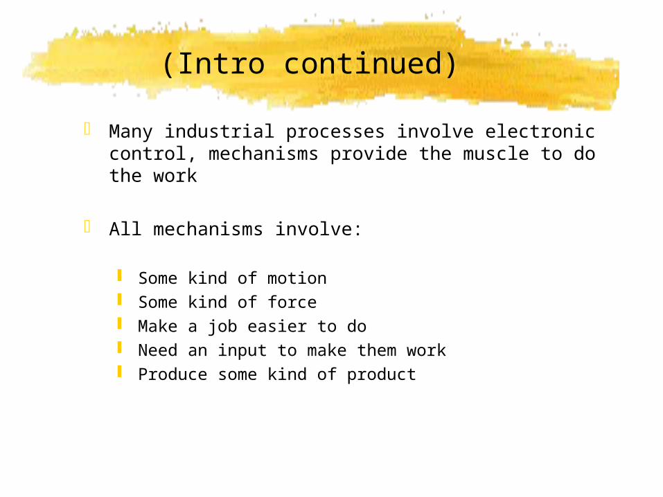
4 Basic Kinds Of Motion
Rotary Turning in a circle
Linear Moving in a straight line
Reciprocating Backwards and forwards movement
Oscillating Swinging back and forwards
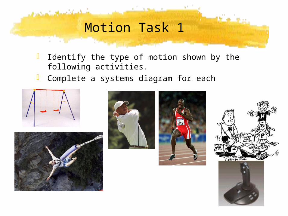
Motion Task 1
Identify the type of motion shown by the following activities.
Complete a systems diagram for each
Motion Task 2
Consider the tools and machines you have used/ seen in CDT
List up to three tools or machines for each basic type of motion
Rotary
Linear
Reciprocating
Oscillating
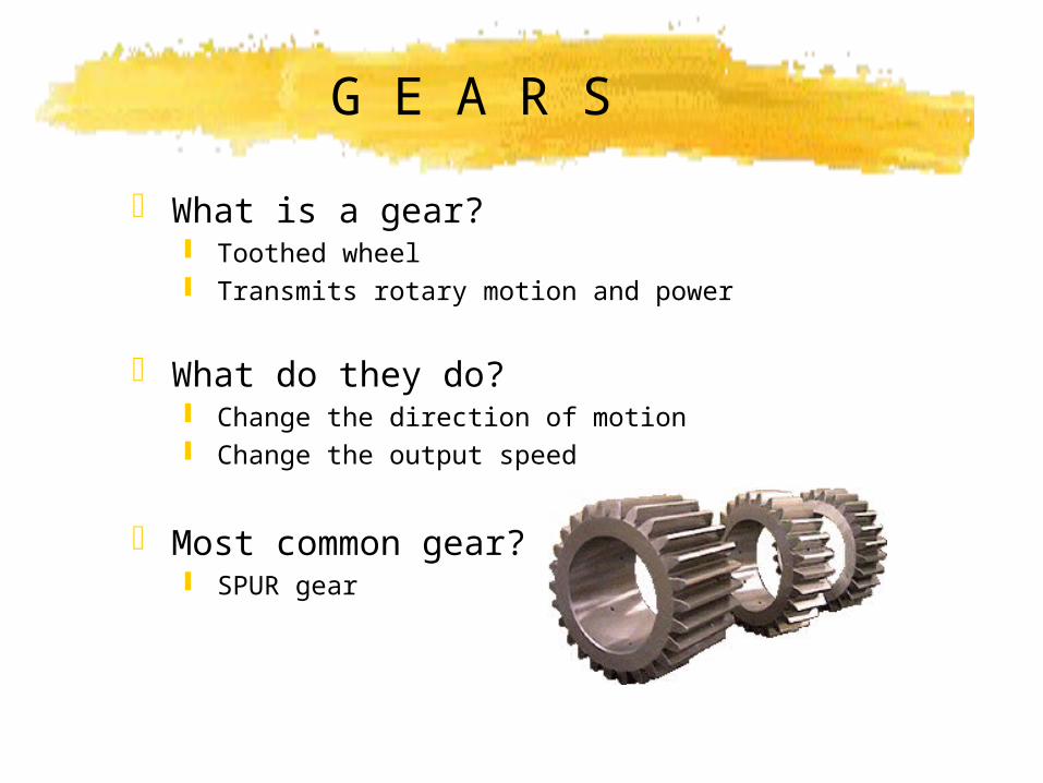
G E A R S
What is a gear? Toothed wheel Transmits rotary motion and power
What do they do? Change the direction of motion Change the output speed
Most common gear? SPUR gear
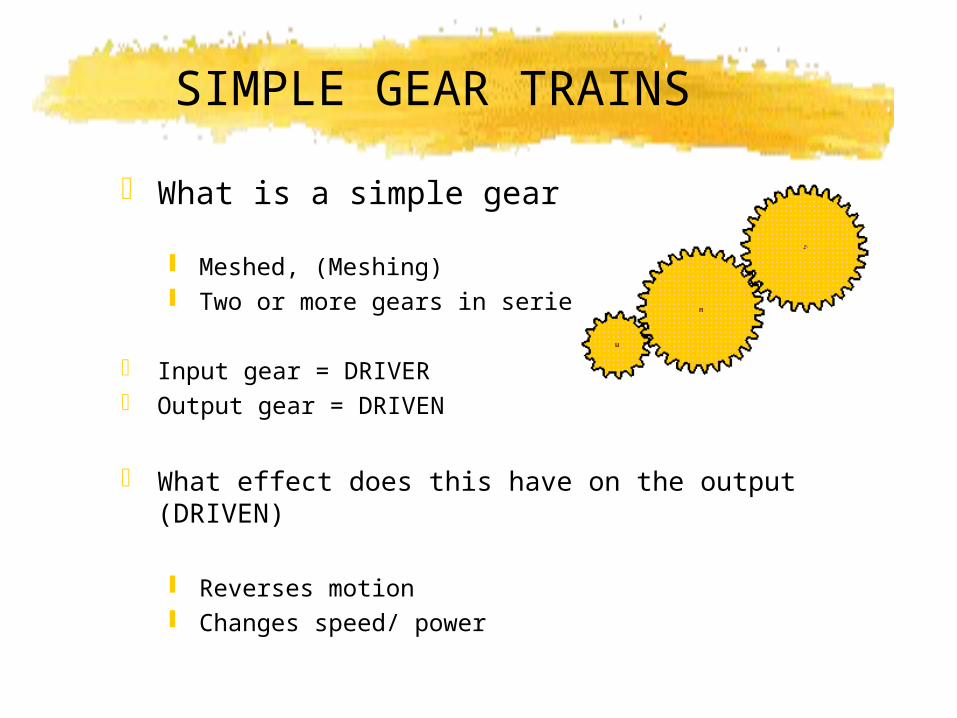
SIMPLE GEAR TRAINS
What is a simple gear train?
Meshed, (Meshing) Two or more gears in series
Input gear = DRIVER Output gear = DRIVEN
What effect does this have on the output (DRIVEN)
Reverses motion Changes speed/ power
Velocity Ratio
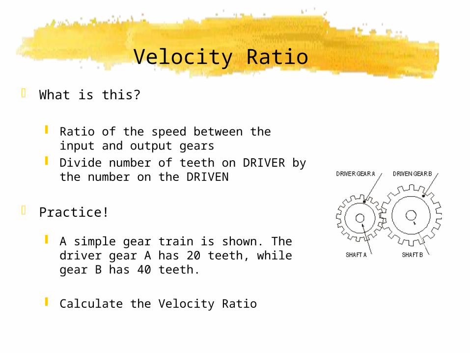
What is this?
Ratio of the speed between the input and output gears
Divide number of teeth on DRIVER by the number on the DRIVEN
Practice!
A simple gear train is shown. The driver gear A has 20 teeth, while gear B has 40 teeth.
Calculate the Velocity Ratio
Solutions
Driver = 20 teethDriven = 40 teeth
V.R. = Driver / Driven = 20/40 = 1/2
Gear velocity/speed ratio is 1 : 2
Calculating Output Speed
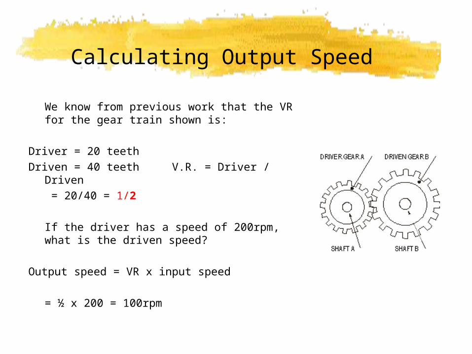
We know from previous work that the VR for the gear train shown is:
Driver = 20 teethDriven = 40 teeth V.R. = Driver / Driven
= 20/40 = 1/2
If the driver has a speed of 200rpm, what is the driven speed?
Output speed = VR x input speed
= ½ x 200 = 100rpm
Idler Gears
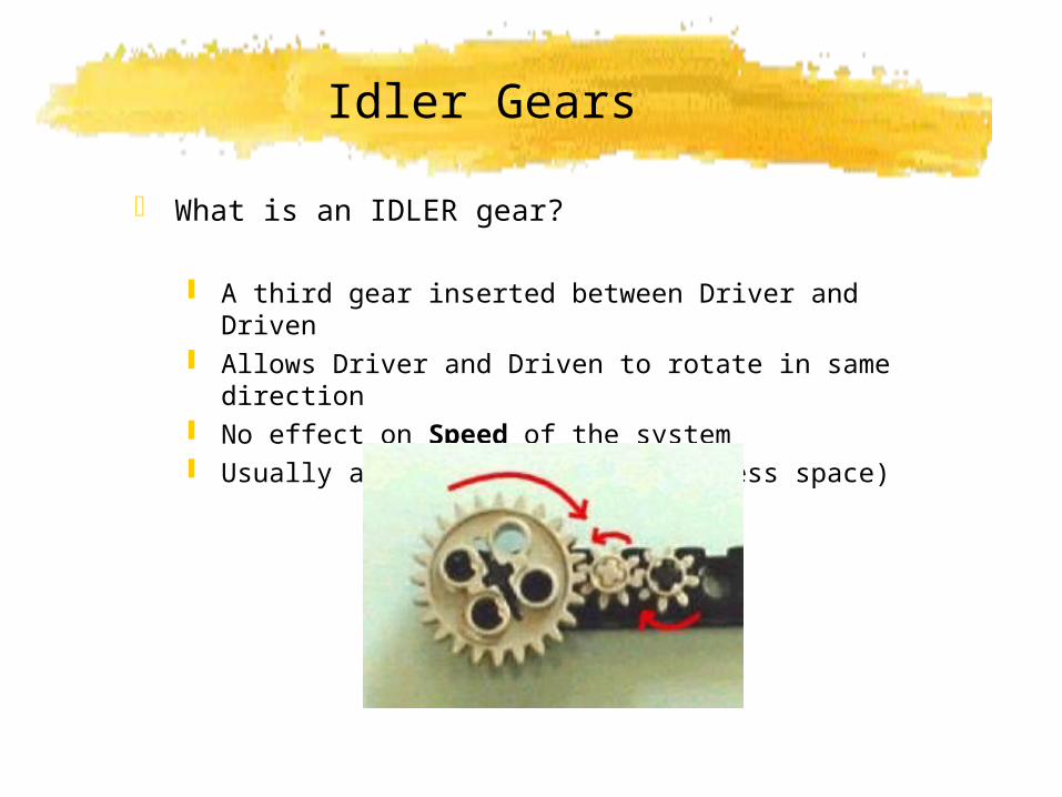
What is an IDLER gear?
A third gear inserted between Driver and Driven Allows Driver and Driven to rotate in same direction No effect on Speed of the system Usually a small gear (takes up less space)
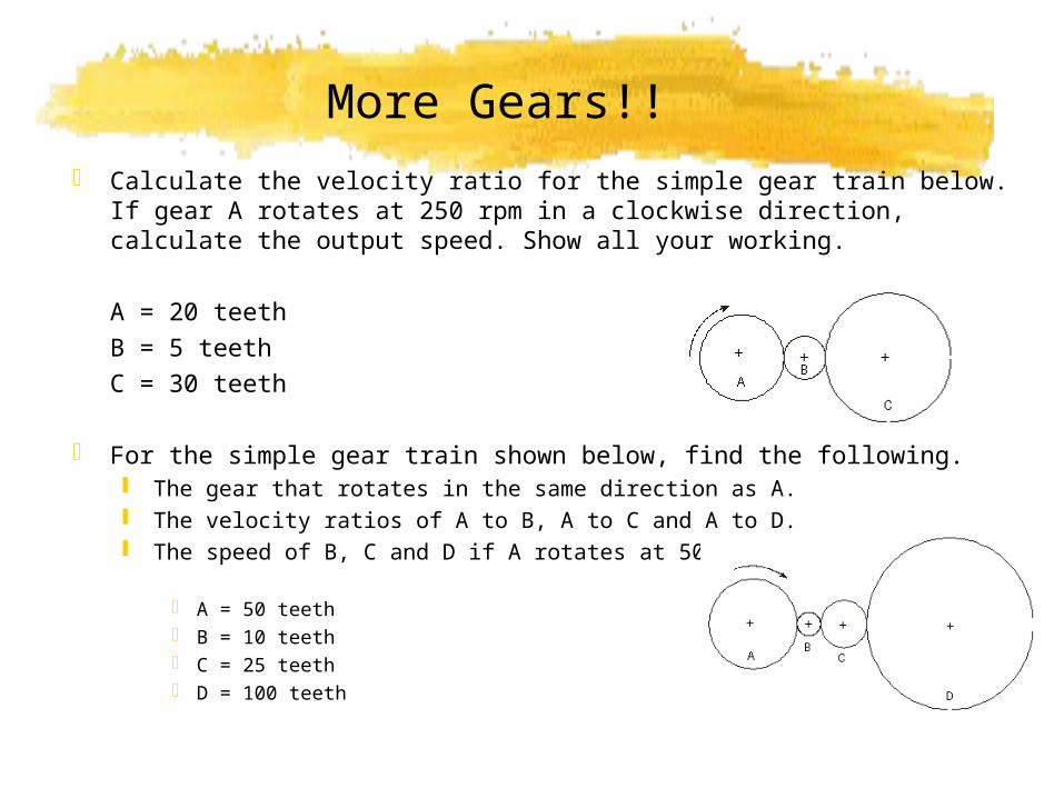
More Gears!! Calculate the velocity ratio for the simple gear train below. If gear A
rotates at 250 rpm in a clockwise direction, calculate the output speed. Show all your working.
A = 20 teethB = 5 teethC = 30 teeth
For the simple gear train shown below, find the following. The gear that rotates in the same direction as A. The velocity ratios of A to B, A to C and A to D. The speed of B, C and D if A rotates at 500 rpm.
A = 50 teeth B = 10 teeth C = 25 teeth D = 100 teeth
Compound Gears
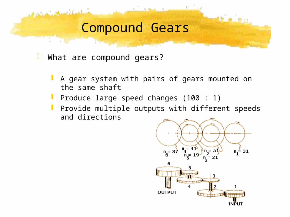
What are compound gears?
A gear system with pairs of gears mounted on the same shaft
Produce large speed changes (100 : 1) Provide multiple outputs with different speeds and
directions
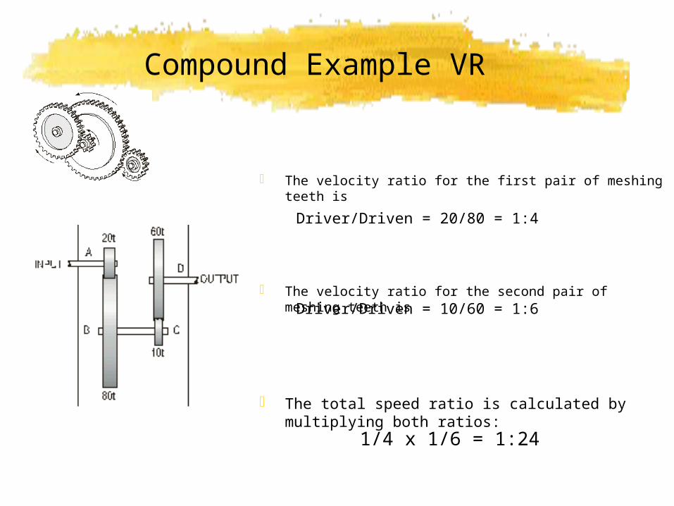
Compound Example VR
The velocity ratio for the first pair of meshing teeth is
The velocity ratio for the second pair of meshing teeth is
The total speed ratio is calculated by multiplying both ratios:
Driver/Driven = 20/80 = 1:4
Driver/Driven = 10/60 = 1:6
1/4 x 1/6 = 1:24
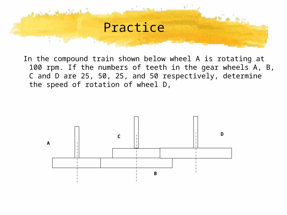
Practice
A
B
C D
In the compound train shown below wheel A is rotating at 100 rpm. If the numbers of teeth in the gear wheels A, B, C and D are 25, 50, 25, and 50 respectively, determine the speed of rotation of wheel D,
Worm and Wheel
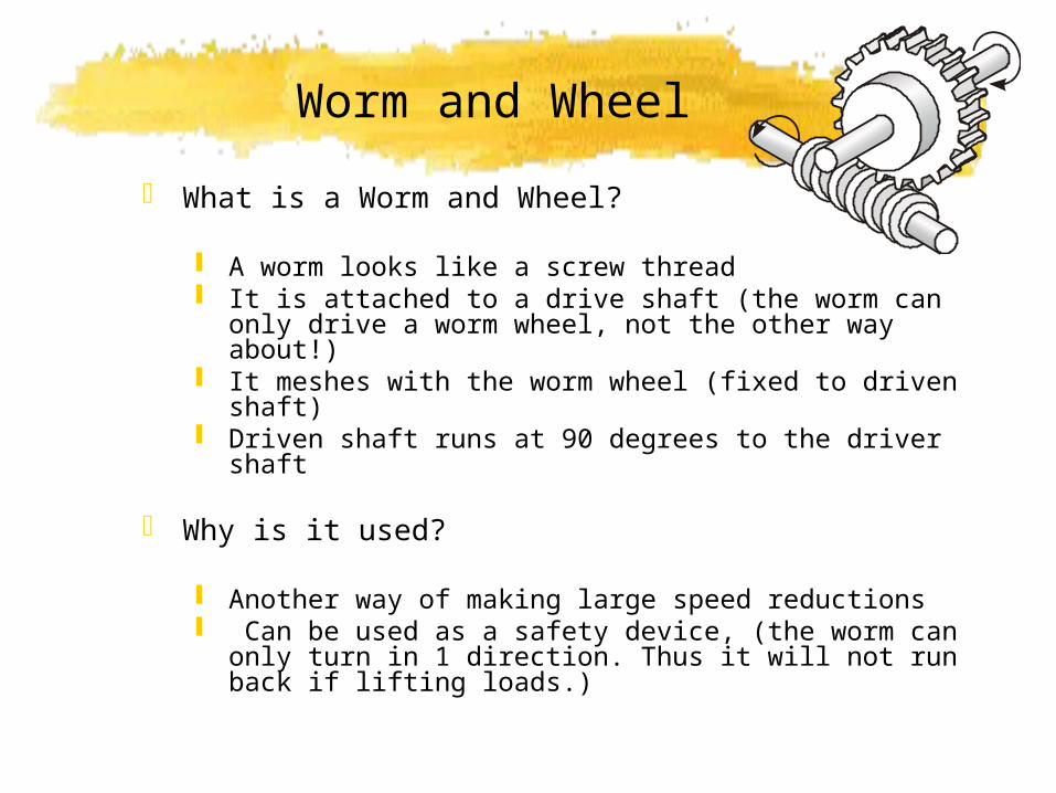
What is a Worm and Wheel?
A worm looks like a screw thread It is attached to a drive shaft (the worm can only drive
a worm wheel, not the other way about!) It meshes with the worm wheel (fixed to driven shaft) Driven shaft runs at 90 degrees to the driver shaft
Why is it used?
Another way of making large speed reductions Can be used as a safety device, (the worm can only
turn in 1 direction. Thus it will not run back if lifting loads.)
Example:
Think of worm as 1 toothed spur gear The velocity ratio between the gears shown is
This would mean that for a motor rotating at 100 rpm, the output driven gear would rotate at only 3.33 rpm.
Try the problems on the white board now.
Velocity ratio = Driver / Driven
Bevel Gears
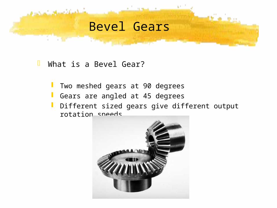
What is a Bevel Gear?
Two meshed gears at 90 degrees Gears are angled at 45 degrees Different sized gears give different output rotation speeds
Tasks
Produce the greatest possible speed within a compound gear train using spur gears with 8t, 16t, 24t and 40t. The driver motor is set at 1 rpm.
Ratchet and Pawl
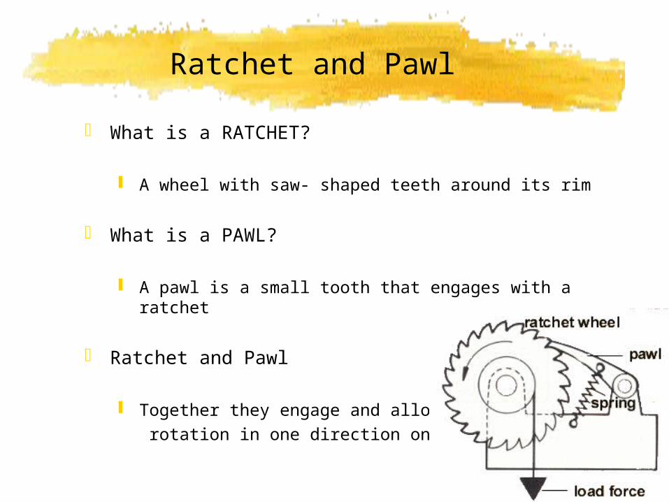
What is a RATCHET?
A wheel with saw- shaped teeth around its rim
What is a PAWL?
A pawl is a small tooth that engages with a ratchet
Ratchet and Pawl
Together they engage and allow rotation in one direction only
Examples: Ratchet and Pawl
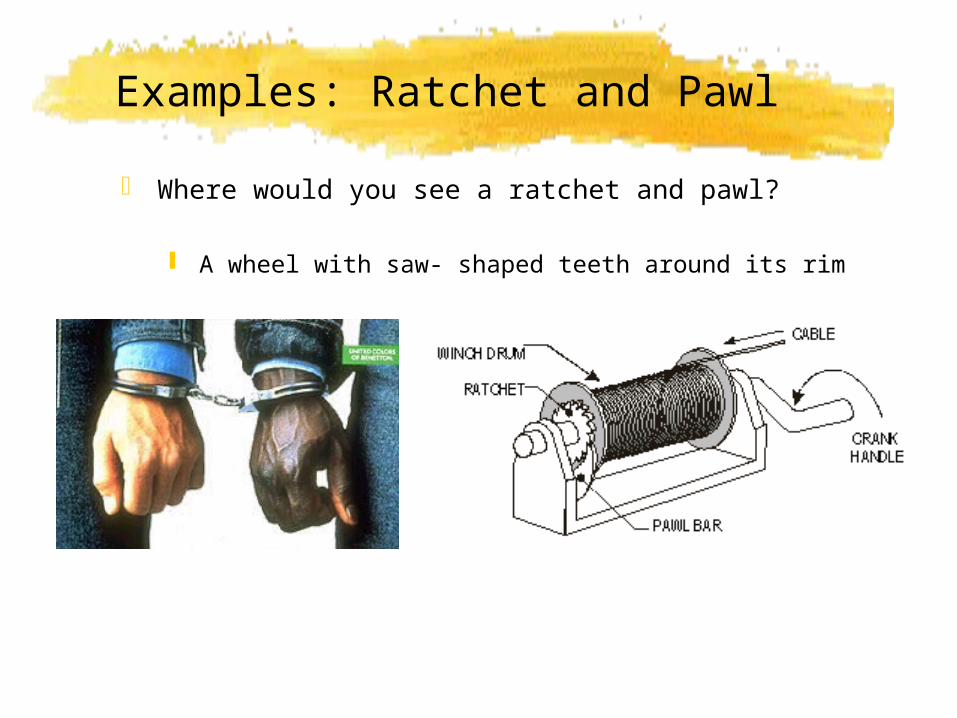
Where would you see a ratchet and pawl?
A wheel with saw- shaped teeth around its rim
Belt and Chain Drives
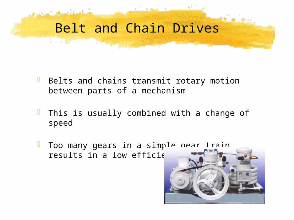
Belts and chains transmit rotary motion between parts of a mechanism
This is usually combined with a change of speed
Too many gears in a simple gear train results in a low efficiency

Belt Drives
A belt is wrapped around two or more pulleys
Pulleys are grooved wheels
The belt is tensioned by one of the pulleys
Also common to use a jockey pulleyFor tensioning purposes
Belts are also angled for greater grip (vee- belt)
Belt Drives
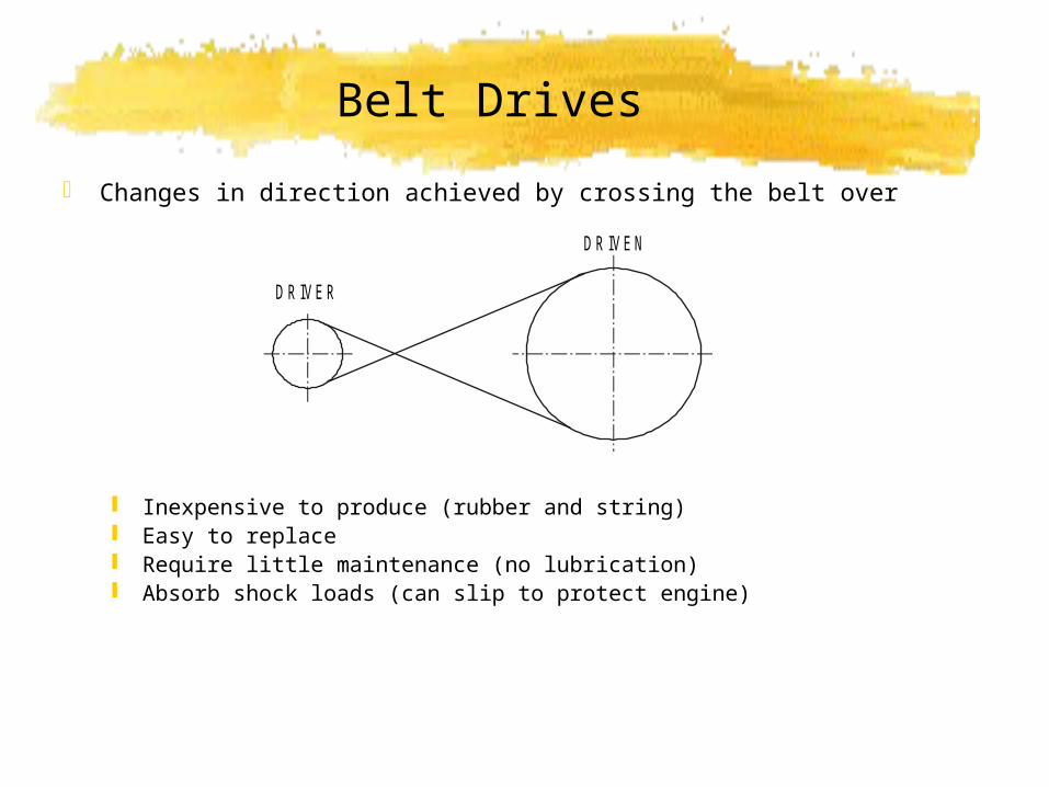
Changes in direction achieved by crossing the belt over
Inexpensive to produce (rubber and string) Easy to replace Require little maintenance (no lubrication) Absorb shock loads (can slip to protect engine)
D R IVEN
D R IVER
Velocity Ratio for belt drives
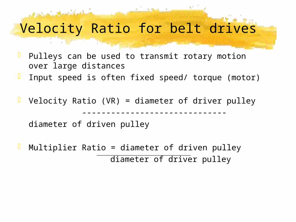
Pulleys can be used to transmit rotary motion over large distances
Input speed is often fixed speed/ torque (motor)
Velocity Ratio (VR) = diameter of driver pulley ------------------------------
diameter of driven pulley
Multiplier Ratio = diameter of driven pulley diameter of driver pulley
Toothed Belts
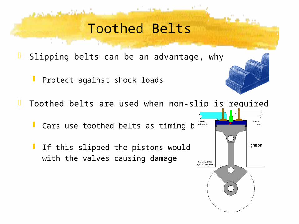
Slipping belts can be an advantage, why?
Protect against shock loads
Toothed belts are used when non-slip is required
Cars use toothed belts as timing belts
If this slipped the pistons would collide with the valves causing damage
Chain Drives
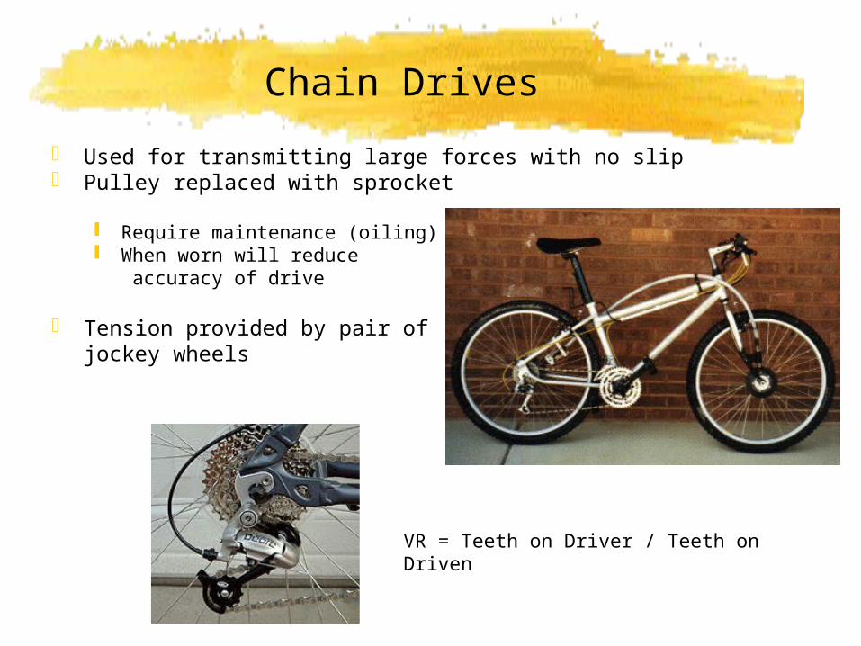
Used for transmitting large forces with no slip Pulley replaced with sprocket
Require maintenance (oiling) When worn will reduce
accuracy of drive
Tension provided by pair of jockey wheels
VR = Teeth on Driver / Teeth on Driven
Chain Drives
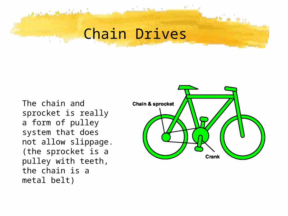
The chain and sprocket is really a form of pulley system that does not allow slippage. (the sprocket is a pulley with teeth, the chain is a metal belt)
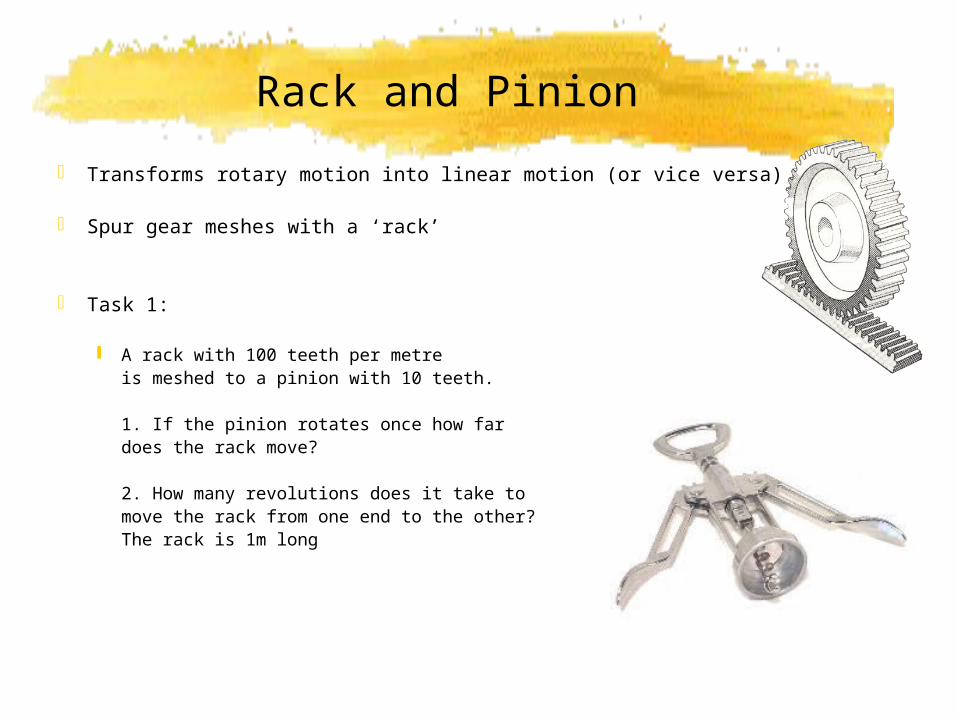
Rack and Pinion
Transforms rotary motion into linear motion (or vice versa)
Spur gear meshes with a ‘rack’
Task 1:
A rack with 100 teeth per metreis meshed to a pinion with 10 teeth.
1. If the pinion rotates once how far does the rack move?
2. How many revolutions does it take to move the rack from one end to the other? The rack is 1m long
Rack and Pinion Solutions
Task 1 (A)
Rack is 1m long with 100T, so each tooth is worth 1000/100 = 10mm
This value is known as the Tooth Pitch of the rack.
If the pinion rotates once, then it moves 10T, so the movement of the rack is 10 x 10 = 100mm
(B) If rack is 1m long then it will take 1000/100 = 10 revolutions to move from one end to the other.
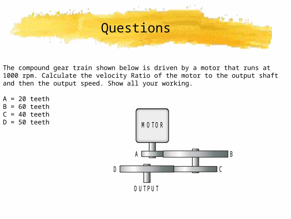
Questions
The compound gear train shown below is driven by a motor that runs at 1000 rpm. Calculate the velocity Ratio of the motor to the output shaft and then the output speed. Show all your working. A = 20 teethB = 60 teethC = 40 teethD = 50 teeth M O TO R
A B
CD
O U TPU T
Gary Plimer 2006
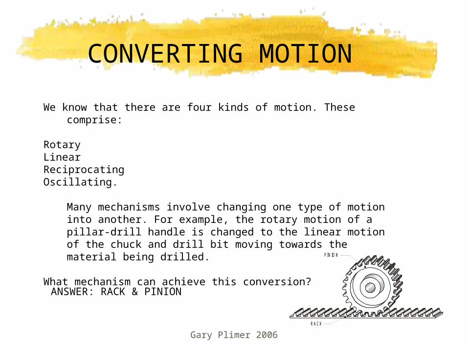
We know that there are four kinds of motion. These comprise:
RotaryLinearReciprocatingOscillating.
Many mechanisms involve changing one type of motion into another. For example, the rotary motion of a pillar-drill handle is changed to the linear motion of the chuck and drill bit moving towards the material being drilled.
What mechanism can achieve this conversion?
CONVERTING MOTION
PIN IO N
R AC K
ANSWER: RACK & PINION
Gary Plimer 2006
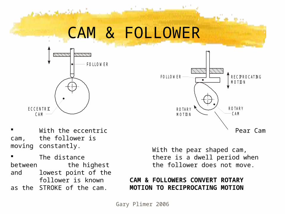
CAM & FOLLOWER
EC CEN TRICCAM
FO LLO W ER
R O TARYC AM
R O TARYM O TIO N
FO LLO W ER R EC IPR O C ATIN GM O TIO N
With the eccentric cam, the follower is moving constantly.
The distance between the highest and
lowest point of the follower is known as the STROKE of the cam.
With the pear shaped cam, there is a dwell period when the follower does not move.
Pear Cam
CAM & FOLLOWERS CONVERT ROTARY MOTION TO RECIPROCATING MOTION
Gary Plimer 2006
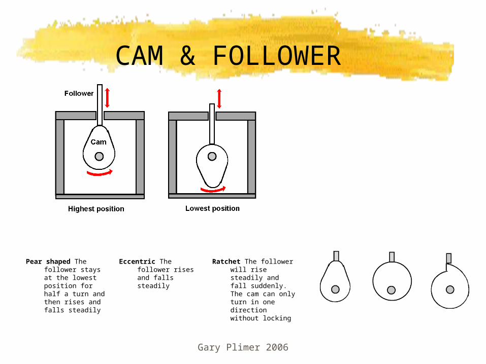
CAM & FOLLOWER
Pear shaped The follower stays at the lowest position for half a turn and then rises and falls steadily
Eccentric The follower rises and falls steadily
Ratchet The follower will rise steadily and fall suddenly. The cam can only turn in one direction without locking
Gary Plimer 2006
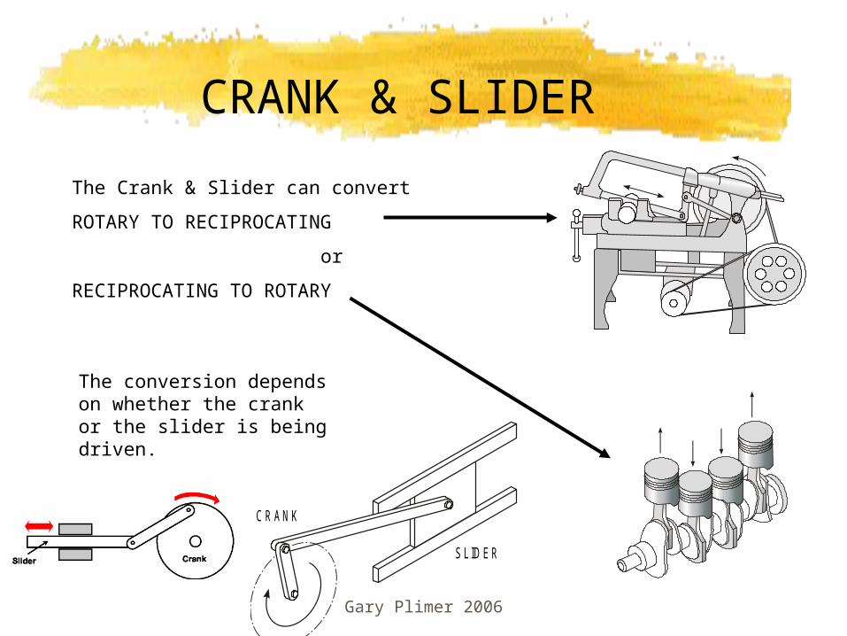
CRANK & SLIDER
C R AN K
SLID ER
The Crank & Slider can convert
ROTARY TO RECIPROCATING
or
RECIPROCATING TO ROTARY
The conversion depends on whether the crank or the slider is being driven.
Gary Plimer 2006
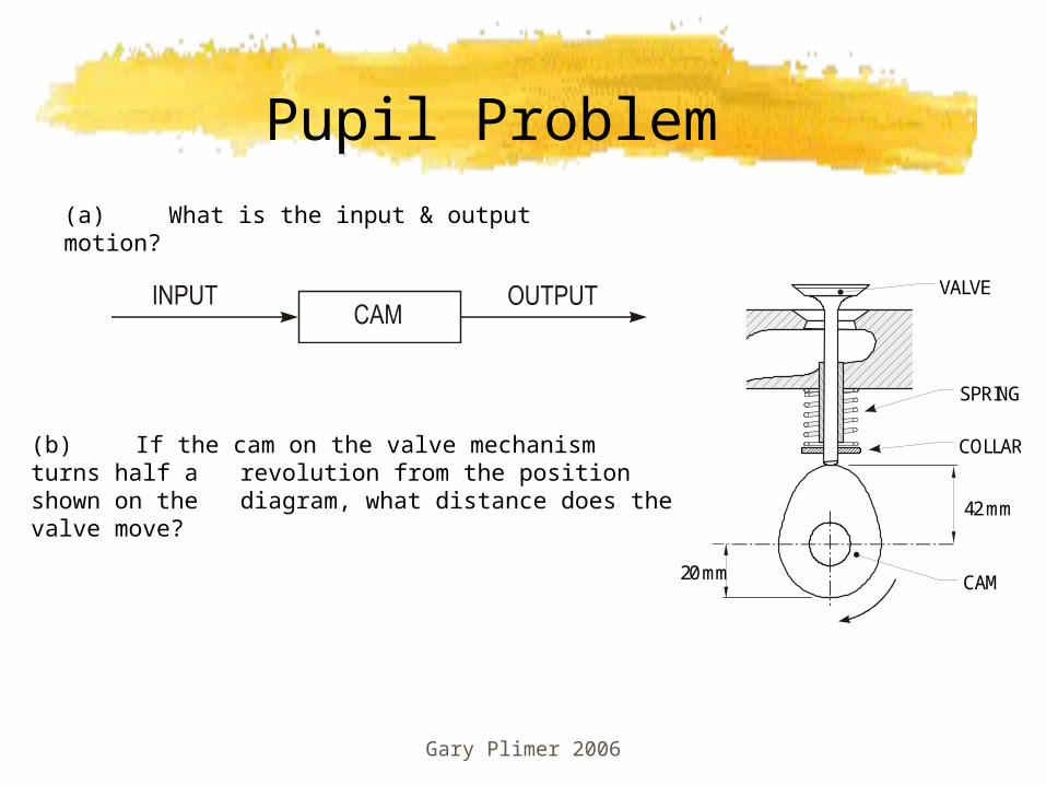
Pupil Problem
CAM
VALVE
SPRING
COLLAR
42 mm
20 mm
(b) If the cam on the valve mechanism turns half a revolution from the position shown on the diagram, what distance does the valve move?
(a) What is the input & output motion?
Friction & Effect
Friction between moving parts reduces the efficiency of the system
Ways in which we can reduce friction
These include:• Lubrication, Oil or grease• Use roller bearings


![Review Article The efficacy of Yunnan Baiyao on ... · unknown exact mechanisms. It has also been shown to regulate immune function and anti-inflammation [19]. YNBY has been widely](https://img.pdfslide.net/doc/110x75/5abf1eef7f8b9ad8278e0bd7/review-article-the-efficacy-of-yunnan-baiyao-on-exact-mechanisms-it-has-also.jpg)


![DYNAMICS CONTROL AND DH PARAMETRIZATION OF · PDF fileDenavit-Hartenberg notation (Fig.1) is widely used in the transformation of coordinate systems of linkages and robot mechanisms[1]](https://img.pdfslide.net/doc/110x75/5a8794817f8b9a882e8dbf44/dynamics-control-and-dh-parametrization-of-notation-fig1-is-widely-used-in.jpg)