Embed Size (px)
Citation preview

COPYRIGHT © NOVEMBER, 2007 BY GRIZZLY INDUSTRIAL, INC.WARNING: NO PORTION OF THIS MANUAL MAY BE REPRODUCED IN ANY SHAPE
OR FORM WITHOUT THE WRITTEN APPROVAL OF GRIZZLY INDUSTRIAL, INC. #JB10062 PRINTED IN CHINA
MODEL T1004226" LAWN SWEEPER
INSTRUCTION SHEET
Figure 1. Inventory 1.
Figure 2. Inventory 2.
H
C D
F
G
E
Inventory (Figures 1 and 2)A. Sweeper Assembly (not shown) ................. 1B. Leaf Bag (not shown) ................................. 1C. Long Bag Rod (27¼") ................................ 1D. Short Bag Rod (25½") ................................ 1E. Frame Handle ............................................. 1F. Frame Legs ................................................ 2G. Hex Bolts M6-1 x 30 ................................... 4H. Lock Washers 6mm ................................... 4I. Hex Nuts M6-1 ........................................... 4J. Carriage Bolts M6-1 x 30 ........................... 4K. Lock Nuts M6-1 .......................................... 4L. Bag Clips .................................................... 4M. Hairpin Cotter Pins ..................................... 2N. Rubber Caps .............................................. 2
To reduce the risk of injury from using this product:
• Do not allow anyone to operate the sweeper without proper training.
• Do not allow children to use the sweeper.
• Always wear proper eye protection when using the sweeper.
• If an object becomes lodged in the sweeper, do not attempt to remove it while the sweeper brush is moving.
• Keep all hardware tightened to be sure the sweeper is in safe working order.
• Thoroughly inspect the sweeper for damage after striking any foreign objects.
J
I
K
L
M
N

-2- T10042 26" Lawn Sweeper
4. Attach the rubber caps to the end of the short bag rod and insert the rod into the slot in the sweeper assembly, as shown in Figure 6.
Figure 6. Securing short bag rod.
Rubber Cap
Slot
Short Bag Rod
Assembly1. Assemble and attach the frame to the sweep-
er assembly as shown in Figure 3. Refer to Figure 2 for hardware identification.
Sweeper Assembly
Frame Handle
Frame Leg
2. Slide the long bag rod into the upper leaf bag pocket and slide the short bag rod into the lower leaf bag pocket. Hook the long bag rod into the two upper bag clips, as shown in Figure 4.
Figure 4. Bag assembly.
Short Bag Rod
Long Bag Rod
Leaf Bag
Upper Bag Clips
3. Secure the long bag rod using the hairpin cot-ter pins, as shown in Figure 5.
Figure 5. Securing long bag rod.
Hairpin Cotter Pin
Long Bag Rod
Figure 7. Elastic strap and lower bag hook.
Elastic Strap
Lower Bag Hook
5. Hook the elastic strap to the lower bag hook, as shown in Figure 7.
Detail A
Figure 3. Frame assembly.
J,L,K
G,H,I (x2)
J,L,K
Detail A Detail B
Detail B
-3- T10042 26" Lawn Sweeper
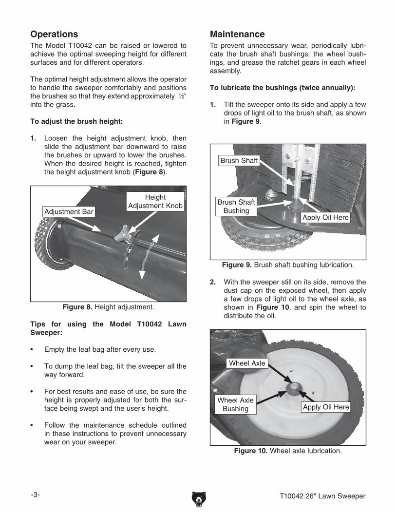
OperationsThe Model T10042 can be raised or lowered to achieve the optimal sweeping height for different surfaces and for different operators.
The optimal height adjustment allows the operator to handle the sweeper comfortably and positions the brushes so that they extend approximately ½" into the grass.
To adjust the brush height:
1. Loosen the height adjustment knob, then slide the adjustment bar downward to raise the brushes or upward to lower the brushes. When the desired height is reached, tighten the height adjustment knob (Figure 8).
Figure 8. Height adjustment.
Adjustment Bar
Height Adjustment Knob
Tips for using the Model T10042 Lawn Sweeper:
• Empty the leaf bag after every use.
• To dump the leaf bag, tilt the sweeper all the way forward.
• For best results and ease of use, be sure the height is properly adjusted for both the sur-face being swept and the user's height.
• Follow the maintenance schedule outlined in these instructions to prevent unnecessary wear on your sweeper.
MaintenanceTo prevent unnecessary wear, periodically lubri-cate the brush shaft bushings, the wheel bush-ings, and grease the ratchet gears in each wheel assembly.
To lubricate the bushings (twice annually):
1. Tilt the sweeper onto its side and apply a few drops of light oil to the brush shaft, as shown in Figure 9.
Figure 9. Brush shaft bushing lubrication.
Apply Oil Here
Brush Shaft
Brush Shaft Bushing
2. With the sweeper still on its side, remove the dust cap on the exposed wheel, then apply a few drops of light oil to the wheel axle, as shown in Figure 10, and spin the wheel to distribute the oil.
Figure 10. Wheel axle lubrication.
Apply Oil Here
Wheel Axle
Wheel Axle Bushing

-4- T10042 26" Lawn Sweeper
3. Replace the dust cap and allow the oil to pen-etrate for a few minutes. Flip the sweeper on to the other side and repeat Steps 1-3 for the other bushings.
Every two years, the ratchet assemblies in each wheel should be cleaned and greased.
Note: When performing this procedure, take notes on the position of all washers, spacers, and retaining rings. Work on one side at a time to avoid mixing directional components.
To grease the ratchet assemblies:
1. Remove the dust cover and the retaining clip holding the wheel, then remove the wheel (Figures 11 and 12).
2. Remove the retaining clip from the brush shaft, then remove the spacers (Figure 13).
Figure 14. Ratchet gear assembly.
Ratchet Gear
Ratchet Pin
Brush Shaft
4. Thoroughly clean, then grease the parts using multipurpose grease. Re-assemble in the reverse order from disassembly.
5. Repeat for the other wheel.
Figure 12. Wheel removed.
Ratchet Gear
Wheel
Figure 11. Retaining clip removal.
Wheel
3. Remove the ratchet gear and the ratchet pin (Figure 14).
Figure 13. Ratchet gear assembly.
Ratchet Gear Retaining Clip
Brush Shaft
Ratchet GearSpacers

-5- T10042 26" Lawn Sweeper
Figure 15. Brush assembly (end view).
With extensive use, the brushes on the Model T10042 may become worn and require replace-ment.
To replace the brushes:
1. Tilt the sweeper all the way forward to allow easy access to the brushes. For the sake of simplicity, only replace one brush at a time.
2. Remove the lock nuts and hex bolts indicated in Figure 15, and remove the old brushes. It is not necessary to remove the bolts and nuts connecting the brush holder to the brush shaft.
3. Install the new brush, making sure the over-lap bristles are properly oriented in relation-ship to the direction of brush rotation, as shown in Figure 15. Tighten the hex nuts.
Brush Rotation
Brush Rotation
Remove
Overlap Bristles
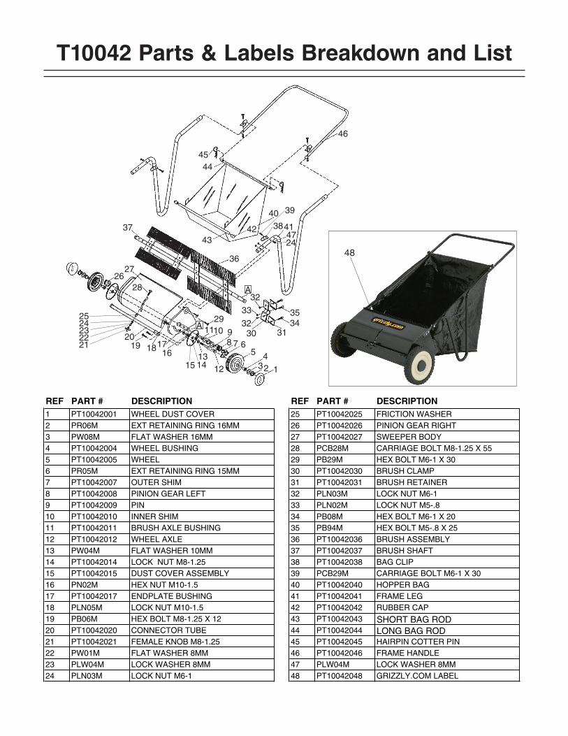
T10042 Parts & Labels Breakdown and List
�����
���������
�
��������
��������
����������
��
��
����
��
��
�� ����
��
��
����
��
�� ��
����
������
����
��
��
REF PART # DESCRIPTION REF PART # DESCRIPTION1 PT10042001 WHEEL DUST COVER 25 PT10042025 FRICTION WASHER2 PR06M EXT RETAINING RING 16MM 26 PT10042026 PINION GEAR RIGHT3 PW08M FLAT WASHER 16MM 27 PT10042027 SWEEPER BODY4 PT10042004 WHEEL BUSHING 28 PCB28M CARRIAGE BOLT M8-1.25 X 555 PT10042005 WHEEL 29 PB29M HEX BOLT M6-1 X 306 PR05M EXT RETAINING RING 15MM 30 PT10042030 BRUSH CLAMP7 PT10042007 OUTER SHIM 31 PT10042031 BRUSH RETAINER8 PT10042008 PINION GEAR LEFT 32 PLN03M LOCK NUT M6-19 PT10042009 PIN 33 PLN02M LOCK NUT M5-.810 PT10042010 INNER SHIM 34 PB08M HEX BOLT M6-1 X 2011 PT10042011 BRUSH AXLE BUSHING 35 PB94M HEX BOLT M5-.8 X 2512 PT10042012 WHEEL AXLE 36 PT10042036 BRUSH ASSEMBLY13 PW04M FLAT WASHER 10MM 37 PT10042037 BRUSH SHAFT14 PT10042014 LOCK NUT M8-1.25 38 PT10042038 BAG CLIP15 PT10042015 DUST COVER ASSEMBLY 39 PCB29M CARRIAGE BOLT M6-1 X 3016 PN02M HEX NUT M10-1.5 40 PT10042040 HOPPER BAG17 PT10042017 ENDPLATE BUSHING 41 PT10042041 FRAME LEG18 PLN05M LOCK NUT M10-1.5 42 PT10042042 RUBBER CAP19 PB06M HEX BOLT M8-1.25 X 12 43 PT10042043 SHORT BAG ROD20 PT10042020 CONNECTOR TUBE 44 PT10042044 LONG BAG ROD21 PT10042021 FEMALE KNOB M8-1.25 45 PT10042045 HAIRPIN COTTER PIN22 PW01M FLAT WASHER 8MM 46 PT10042046 FRAME HANDLE23 PLW04M LOCK WASHER 8MM 47 PLW04M LOCK WASHER 8MM24 PLN03M LOCK NUT M6-1 48 PT10042048 GRIZZLY.COM LABEL
48