Embed Size (px)
Citation preview
INVERSE CLASS-F POWER AMPLIFIERUSING THE METAMATERIALSTRUCTURE ON THE HARMONICCONTROL CIRCUIT
Hyoungjun Kim and Chulhun SeoSchool of Electronic Engineering, Soongsil University, Sangdo-Dong511, Dongjak-Gu, Seoul 156-743, Korea; Corresponding author:[email protected]
Received 29 February 2008
ABSTRACT: In this study, the inverse class-F power amplifier at 1.8GHz using the harmonic control circuit based on a metamaterial struc-ture is proposed and experimentally tested. The harmonic control circuithas been used with transmission line and metamaterial structure to openthe 2nd harmonics, to short the 3rd harmonics, and to match the funda-mental frequency to 50 �. The interesting properties of the metamate-rial structure allow a size reduction of the harmonic control circuit aswell simplification of the design. A detailed analysis of the metamaterialstructures based on the equivalent circuit model is provided. The pro-posed harmonic control circuit has been used to design the inverseclass-F power amplifier with maximum PAE of 70.4%. © 2008 WileyPeriodicals, Inc. Microwave Opt Technol Lett 50: 2881–2884, 2008;Published online in Wiley InterScience (www.interscience.wiley.com).DOI 10.1002/mop.23836
Key words: inverse class-F; metamaterial; power-added efficiency;power amplifier; harmonic control circuit
1. INTRODUCTION
The significance of high-output amplifiers in wireless communi-cation has been emphasized because of the rapid distribution ofmobile communication systems. The current high-power amplifier(HPA) requires high power-added efficiency and linearity [1]. DCpower consumption efficiency is an important design goal in RFfront-end design for handsets as well as base-stations. High power-added efficiency increases the usage time and allows for moresimplified cooling systems. Because the power amplifier consumesmost of the DC power in the RF chain, the focus of design ofpower amplifier has been placed on improving its power addedefficiency. Different classes of power amplifiers exist to achievehigh power-added efficiency (Class D, E, F and inverse class-F)[2]. It is well known that RF performances of a transistor are fixedby the bias and matching conditions. The usual classes (A, AB, andB) do not allow a very high efficiency. The solution is to use higherpower-added efficiency classes, as class-F and inverse class-Fpower amplifier, which are based on specific waveforms of thedrain-to-source voltage and the drain current. The so-called inverseclass-F power amplifier [3] is defined with a squared waveform forthe drain current and a sinusoid for the drain voltage. Thesewaveforms can be obtained by the control of voltage and currentharmonics. This power amplifier, which employs open circuits ateven-order harmonics and short circuits at odd-order harmonics,can deliver even higher power-added efficiency than class-F de-sign, under conditions of limited supply voltage. In this study, theharmonic control circuit based on transmission line and metama-terial structure has been used to obtain the squared waveform forthe drain current and a sinusoid waveform for the drain voltage forinverse class-F power amplifier.
2. METAMATERIAL THEORY
Metamaterials are artificially loaded media that employ negativepermittivity and permeability in finite frequency ranges. The meta-
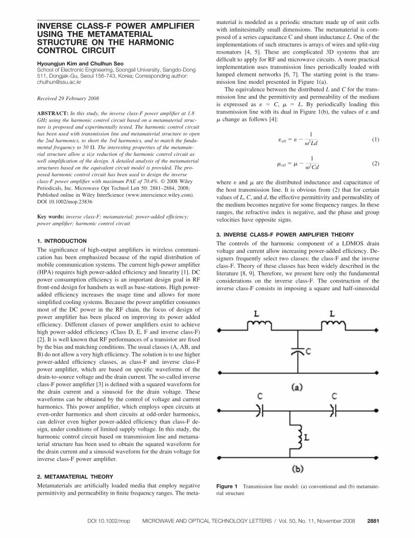
material is modeled as a periodic structure made up of unit cellswith infinitesimally small dimensions. The metamaterial is com-posed of a series capacitance C and shunt inductance L. One of theimplementations of such structures is arrays of wires and split-ringresonators [4, 5]. These are complicated 3D systems that aredifficult to apply for RF and microwave circuits. A more practicalimplementation uses transmission lines periodically loaded withlumped element networks [6, 7]. The starting point is the trans-mission line model presented in Figure 1(a).
The equivalence between the distributed L and C for the trans-mission line and the permittivity and permeability of the mediumis expressed as � � C, � � L. By periodically loading thistransmission line with its dual in Figure 1(b), the values of � and� change as follows [4]:
�eff � � �1
�2Ld(1)
�eff � � �1
�2Cd(2)
where � and � are the distributed inductance and capacitance ofthe host transmission line. It is obvious from (2) that for certainvalues of L, C, and d, the effective permittivity and permeability ofthe medium becomes negative for some frequency ranges. In theseranges, the refractive index is negative, and the phase and groupvelocities have opposite signs.
3. INVERSE CLASS-F POWER AMPLIFIER THEORY
The controls of the harmonic component of a LDMOS drainvoltage and current allow increasing power-added efficiency. De-signers frequently select two classes: the class-F and the inverseclass-F. Theory of these classes has been widely described in theliterature [8, 9]. Therefore, we present here only the fundamentalconsiderations on the inverse class-F. The construction of theinverse class-F consists in imposing a square and half-sinusoidal
Figure 1 Transmission line model: (a) conventional and (b) metamate-rial structure
DOI 10.1002/mop MICROWAVE AND OPTICAL TECHNOLOGY LETTERS / Vol. 50, No. 11, November 2008 2881

waveform, respectively, for drain-current and drain-to-source volt-age. Figure 2 presents the waveforms of drain-current and drain-to-source voltage.
To obtain these waveforms, it is necessary to control thetransistor output impedance at different harmonics. For the funda-mental frequency, load impedance must be matched to 50 � value.In inverse class-F theory, the odd harmonics are short-circuitedand even harmonics are loaded with open-circuits. These idealwaveforms of inverse class-F power amplifiers can be analyzedusing Fourier series expansion. This analysis is employed to sep-arate DC, fundamental, and harmonic components of the idealwaveforms and gives expressions for parameters as DC powerdissipation, fundamental RF output power, and the fundamentalload impedance required to obtaining a proper RF output powerusing load-pull method. Figure 2 shows the ideal current andvoltage waveforms of the inverse class-F power amplifiers. Thecurrent and voltage waveforms are expanded using Fourier seriesas follows:
iD �id
2�1 �4
� �n�1,3,5. . .
1
nsinn�0t� (3)
vD � vK � �vmax � vK� � �1
��
1
2sin�0t �
2
� �n�2,4,6. . .
1
n2 � 1cosn�0t�.
(4)
In general, we have considered only the three first harmonics. So,the optimal drain load impedance ZL is as follows:
ZL� f0� � Zopt (5)
ZL�2f0� � � (6)
ZL�3f0� � 0 (7)
where fo is the fundamental frequency and Zopt is the optimal loadimpedance. Practical values of load impedance could be somewhatdifferent from their theoretical values. So, optimal values must beobtained by measurements with a multiharmonic load-pull benchor by simulations with a nonlinear model and harmonic balancesimulator. In this study, the second technique was used to inverseclass-F power amplifier.
4. HARMONIC CONTROL CIRCUIT FOR INVERSE CLASS-FPOWER AMPLIFIER
The harmonic control circuit for inverse class-F was achieved byusing transmission lines and metamaterial structures. As it wasstated before, an inverse class-F power amplifier needs to have itseven harmonics opened and the odd harmonics short circuited. Byusing a combination of an open-short stub and a metamaterialstructure composed of series C and shunt L, it is possible toachieve such constraints for the 2nd and 3rd harmonics. The circuitschematic is shown in Figure 3.
Figure 4 shows that the harmonic control circuit has perfectlyopen and perfectly short impedances for the 2nd harmonic and 3rdharmonic components, respectively. The output matching networkfor the inverse class-F power amplifier was designed for optimumperformance with the harmonic control network. In this study,lumped elements were used to realize the metamaterial structure,and the right-handed portion of the line is implemented by using atransmission line.
Figure 2 Voltage and current waveforms of inverse class-F with allharmonics. [Color figure can be viewed in the online issue, which isavailable at www.interscience.wiley.com]
Figure 3 Schematic of harmonic control circuit using transmission linesand metamaterial structure for inverse class-F operation. [Color figure canbe viewed in the online issue, which is available at www.interscience.wiley.com]
Figure 4 Harmonic control circuit’s impedance using transmission linesand metamaterial structure for inverse class-F operation. [Color figure canbe viewed in the online issue, which is available at www.interscience.wiley.com]
2882 MICROWAVE AND OPTICAL TECHNOLOGY LETTERS / Vol. 50, No. 11, November 2008 DOI 10.1002/mop

5. IMPLEMENTATION OF INVERSE CLASS-F POWERAMPLIFIER
A Teflon board with a permittivity of 3.2 has been used in thisresearch. In addition, MRF281SR1 of Freescale has been used inpower amplifier. A load-pull simulation using ADS2005A wasapplied to determine an optimal impedance of output matchingpoint. The harmonic control circuit was designed using conven-tional transmission line and lumped elements. The via connectionis substituted for shunt inductor. Figure 5 shows the fabrication of
harmonic control circuit.Figure 6 shows impedance of 1st, 2nd, and 3rd frequency of
harmonic control circuit. The fundamental frequency is matched tooptimal impedance (50.34�j5.5 �), 2nd harmonic is open imped-ance (690-j441 �), and 3rd harmonic is short impedance(0.49�j93 �).
Figure 7 shows the fabricated inverse class-F power amplifierwith the harmonic control circuit using the transmission line andmetamaterial structure. The device was biased with a drain voltageof 26 V and a gate voltage of 3.2 V.
Figure 5 Photograph of fabricated harmonic control circuit. [Color fig-ure can be viewed in the online issue, which is available at www.interscience.wiley.com]
Figure 6 Measured data of impedance 1st, 2nd, and 3rd frequency of harmonic control circuit by network analyzer. [Color figure can be viewed in theonline issue, which is available at www.interscience.wiley.com]
Figure 7 Photograph of fabricated inverse class-F power amplifier usingthe transmission line and the metamaterial as harmonic control circuit.[Color figure can be viewed in the online issue, which is available atwww.interscience.wiley.com]
DOI 10.1002/mop MICROWAVE AND OPTICAL TECHNOLOGY LETTERS / Vol. 50, No. 11, November 2008 2883
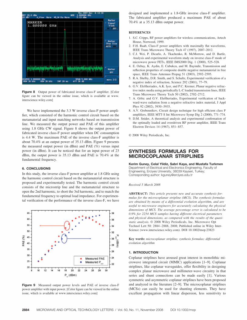
We have implemented the 3.3 W inverse class-F power ampli-fier, which consisted of the harmonic control circuit based on themetamaterial and input matching networks based on transmissionline. We measured the output power and PAE of this amplifierusing 1.8 GHz CW signal. Figure 8 shows the output power offabricated inverse class-F power amplifier when DC consumptionis 4.4 W. The maximum PAE of the inverse class-F amplifier isabout 70.4% at an output power of 35.13 dBm. Figure 9 presentsthe measured output power (in dBm) and PAE (%) versus inputpower (in dBm). It can be noticed that for an input power of 23dBm, the output power is 35.13 dBm and PAE is 70.4% at thefundamental frequency.
6. CONCLUSIONS
In this study, the inverse class-F power amplifier at 1.8 GHz usingthe harmonic control circuit based on the metamaterial structure isproposed and experimentally tested. The harmonic control circuitconsists of the microstrip line and the metamaterial structure toopen the 2nd harmonic, to short the 3rd harmonic, and to match thefundamental frequency to optimal load impedance. For experimen-tal verification of the performance of the inverse class-F, we have
designed and implemented a 1.8-GHz inverse class-F amplifier.The fabricated amplifier produced a maximum PAE of about70.4% at a 35.13 dBm output power.
REFERENCES
1. S.C. Cripps, RF power amplifiers for wireless communications, ArtechHouse, Norwood, 1999.
2. F.H. Raab, Class-F power amplifiers with maximally flat waveforms,IEEE Trans Microwave Theory Tech 47 (1997), 2007–2012.
3. C.J. Wei, P. Dicarlo, A. Tkachenko, R. McMorrow, and D. Bartle,Analysis and experimental waveform study on inverse class-F mode ofmicrowave power FETs, IEEE IMS2000 Dig. 1 (2000), 525–528.
4. E. Ozbay, K. Aydin, E. Cubukcu, and M. Bayindir, Transmission andreflection properties of composite double negative metamaterial in freespace, IEEE Trans Antennas Propag 51 (2003), 2592–2595.
5. R.A. Shelby, D.R. Smith, and S. Schultz, Experimental verification of anegative index of refraction, Science 292 (2001), 77–79.
6. G.V. Eleftheriades, A.K. Iyer, and P.C. Kremer, Planar negative refrac-tive index media using periodically L-C loaded transmission lines, IEEETrans Microwave Theory Tech 50 (2002), 2702–2712.
7. A. Grbic and G.V. Eleftheriades, Experimental verification of back-ward-wave radiation from a negative refractive index material, J ApplPhys 92 (2002), 5930–5935.
8. A.V. Grebennikov, Circuit design technique for high efficient class Famplifiers, IEEE MTT-S Int Microwave Symp Dig 2 (2000), 771–774.
9. D.M. Snider, A theoretical analysis and experimental confirmation ofthe optimally loaded and overdriven RF power amplifier, IEEE TransElectron Devices 14 (1967), 851–857.
© 2008 Wiley Periodicals, Inc.
SYNTHESIS FORMULAS FORMICROCOPLANAR STRIPLINES
Kerim Guney, Celal Yildiz, Sabri Kaya, and Mustafa TurkmenDepartment of Electrical and Electronics Engineering, Faculty ofEngineering, Erciyes University, 38039 Kayseri, Turkey;Corresponding author: [email protected]
Received 5 March 2008
ABSTRACT: This article presents new and accurate synthesis for-mulas for the microcoplanar stripline (MCS). The synthesis formulasare obtained by means of a differential evolution algorithm, and areuseful to microwave engineers for accurately calculating the physicaldimensions of MCS. The average percentage error is calculated to be0.9% for 2254 MCS samples having different electrical parametersand physical dimensions, as compared with the results of the quasi-static analysis. © 2008 Wiley Periodicals, Inc. Microwave OptTechnol Lett 50: 2884 –2888, 2008; Published online in Wiley Inter-Science (www.interscience.wiley.com). DOI 10.1002/mop.23823
Key words: microcoplanar stripline; synthesis formulas; differentialevolution algorithm
1. INTRODUCTION
Coplanar striplines have aroused great interest in monolithic mi-crowave integrated circuit (MMIC) applications [1–9]. Coplanarstriplines, like coplanar waveguides, offer flexibility in designingcomplex planar microwave and millimeter-wave circuitry in thatseries and shunt connections can be made easily [1]. Varioussymmetric and asymmetric coplanar striplines have been proposedand analyzed in the literature [2–9]. The microcoplanar striplines(MCSs) can easily be used for shunting elements. They haveexcellent propagation with linear dispersion, less sensitivity to
Figure 8 Output power of fabricated inverse class-F amplifier. [Colorfigure can be viewed in the online issue, which is available at www.interscience.wiley.com]
Figure 9 Measured output power levels and PAE of inverse class-Fpower amplifier with input power. [Color figure can be viewed in the onlineissue, which is available at www.interscience.wiley.com]
2884 MICROWAVE AND OPTICAL TECHNOLOGY LETTERS / Vol. 50, No. 11, November 2008 DOI 10.1002/mop


![by William Chou...Figure 1.4: Blueprint for metamaterial antenna [8] 1.2 Metamaterial Antenna This thesis is motivated by the potential use of closely spaced metamaterial antennas](https://img.pdfslide.net/doc/110x75/60933e3a3ab2c65ff317d896/by-william-chou-figure-14-blueprint-for-metamaterial-antenna-8-12-metamaterial.jpg)