Embed Size (px)
Citation preview
5th International & 26th All India Manufacturing Technology, Design and Research Conference (AIMTDR 2014) December 12th–14th, 2014, IIT
Guwahati, Assam, India
666-1
Inverse Kinematic Modelling of a 6-DOF(6-CRS) Parallel Spatial
Manipulator
Yogesh Singh1, Santhakumar Mohan2* 1Center for Robotics and Control, Indian Institute of Technology Indore, Madhya Pradesh - 453441, [email protected] 2*Faculty of mechanical Engineering , Indian Institute of Technology Indore, Madhya Pradesh-453441, [email protected]
ABSTRACT
Spatial parallel manipulators have a lot of applications because of their robustness and the accuratenessin the
performance of the system which is associated with parallel kinematic machines. This paper presents a novel six
degrees-of-freedom spatial platform with a 6-PRRS(Prismatic-Revolute-Revolute-Spherical) or 6-CRS (Cylindrical-
Revolute-Spherical) configuration with six active prismatic joints and six rotary joints – all attached with the base
platform - thus giving it six degrees of freedom. The closed-form inverse kinematic solution for the platform is
established in this paper. Each leg have the combination of these joints : one prismatic joint , two rotary joint with
different rotational axes and one spherical joint. Prismatic joint attached with the base platform/fixed platform as a
vertical leg to ensuring better rigidity and control prospects. Its first rotary joint with prismatic joint willact as a
cylindrical joint. All six legs end in a spherical joint which are linked together by the end effector (movable
platform). The inverse kinematic solution is validated through numerical simulation using MATLAB and ADAMS
multibody software and the results are presented here which is showing the accuracy of the closed-form solution.
Keywords : CRS, Spatial parallel manipulators , Cylindrical Joint, Multibody software.
1. INTRODUCTION
All the existing higher degree of freedom industrial
manipulators are based on the serial likage which is
open kinematicchain .In the case of serial
manipulator , all the joint connected with links
assumed to be active joint. Although these type of
manipulator have a larger workspace but it have
some disadvantages like lack of rigidity , lower load
bearing capacity, suffere from error accumulation,
system load not distributed uniformly. Parallel
manipulators, which can perform dexterously in high
speeds due to their closed kinematic loops [2]. Thus,
a high-output velocity is needed and significant for
parallel manipulators to be applied into parallel
manipulators. Parallel robots have been proven to be
more precise than serial robots because they do not
suffer from error accumulation. While this might be
true in theory [2], the genuine reason is that parallel
robots can be built to be stiffer without being bulkier.
Spatial precision positioning devices are often based
on hexapods or tripods. To overcome the limitations
of the serial manipulator many researcher proposed
spatial parallel manipulator including Stewart
platfrom. Many literatures are available in the field of
spatial parallel manipulator , a 3-PPRS configuration
[5],the Glozman mechanism, which uses a 3-PRRS
configuration [4] and many others but its limitation is
observed as their motions are often coupled. Some of
the literature related to the derivation of the inverse
kinematic , forward kinematics, workspace analysis
and singularity analysis of the spatial platform is
listed in the refernces [1,3,6,7,8,9] and their
performance have been analysed. In addition, these
spatial platforms need additional passive chains or
some specific geometric relation between these joints
,which ultimately lead to limited workspace coverage
because of geometrical interference. Hence,
designing of a novel spatial parallel manipulator to
overcome those limitation is a feasible option, such
as the one presented in this paper. One of the primary
advantages of the proposed platform is the attacment
of the active joints or actuators in the base platform
as opposed to platforms like the Stewart platform
where all the active joints are present in the moving
Inverse Kinematic Modelling of a 6-DOF(6-CRS) Parallel Spatial Manipulator
666-2
planes making it more complex to control and bulky
hence restricting the speed associated with the end-
effector.
This arrangement of the actuators on the base
platform is one of the significant features of this
platform ensuring that the proposed platform is
robust and is more accurate than the other spatial
platforms. Another significant feature in the proposed
platform is the decoupled behaviour (singularity free)
of the end effector with in the workspace. This is
because of the absence of any serial linkages in the
links which might cause straightening of the linkages
causing singularities. All the singularities that exist or
that might arise in this platform are only at the
workspace boundaries. Due to this reason work
within the workspace without any coupling effect
ensures seamless flexibility of the system during
tracking operations .
2. DESCRIPTION OF THE PROPOSED
PLATFORM
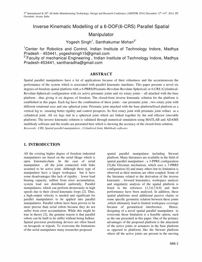
The proposed platform consisting of six legs or
kinematic chains each with a PRRS configuration is
shown in the Figure 1. As shown, the base of
platform has a three vertical prismatic joints which
will actuate and rotate with respect to z axis due to
presence of active prismatic and rotary joint . The
passive link of length � , one end is connected to the
prismatic joint through a revolute joint and the other
end of the link connects to the spherical joint on the
end-effector. The co-ordinates of the base platform is
given by �� = ����������and that of the end of the
prismatic joint is given by �� = ����������. End-
effector(top-platform) is in the shape of an regular
hexagone of constant side length a. The radius of the
circular base platform is � and the co-ordinates of the
spherical joint – which are also the vertices of the
hexagone forming the end effector – is given by � = � �� �� ��.
The joint space vector representing all the joint space
variables is given by � = [�� �� ���������� �� �� �� ����],
where �� represents the rotary joint variables and �� represents the prismatic joint variables, these together
all the joint space variables. The task space co-
ordinates are given with respect to the ground frame, ��� attached to the center of the base platform. A
supplementary frame, ��� attached to the end effector
is used to represent the task space variables which is
given by the vector, � = [� ! " # $ %],
which contains both the position and orientation of
the frame ��� (end-effector). The angles #, $ and %
are the Euler angles for the rotation matrix from the
ground frame to the end-effector frame. The
proposed design uses the co-ordinates of the end-
effector points to derive an inverse kinematic
solution. These co-ordinates can be obtained using
the knowledge of the task space co-ordinates – the
vector D – thus enabling us to arrive at a closed form
solution for the platform.
Figure 1. Proposed Platform Solid Model.
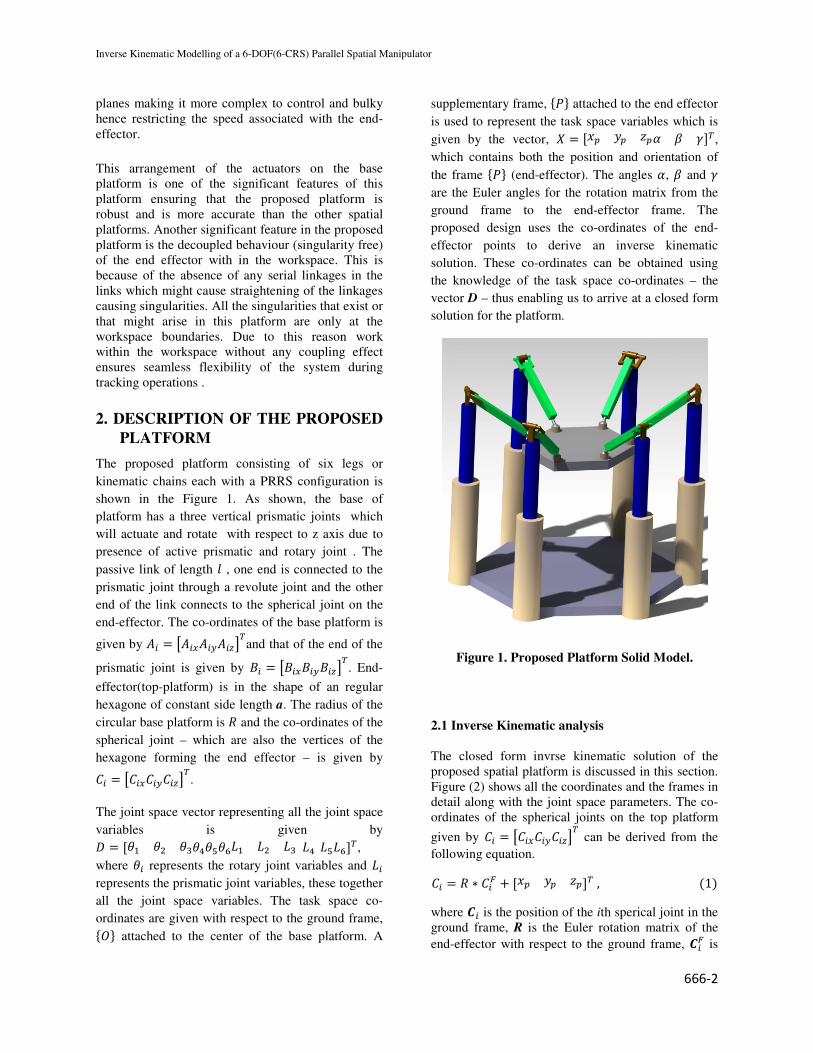
2.1 Inverse Kinematic analysis
The closed form invrse kinematic solution of the
proposed spatial platform is discussed in this section.
Figure (2) shows all the coordinates and the frames in
detail along with the joint space parameters. The co-
ordinates of the spherical joints on the top platform
given by � = � �� �� �� can be derived from the
following equation.
� = � ∗ �' + [� ! " ] , (1)
where -� is the position of the ith sperical joint in the
ground frame, R is the Euler rotation matrix of the
end-effector with respect to the ground frame, -�' is
5th International & 26th All India Manufacturing Technology, Design and Research Conference (AIMTDR 2014) December 12th–14th, 2014, IIT
Guwahati, Assam, India
666-3
the position of the spherical joints in the end effector
frame and the vector [� ! " ] represents the
position of the platform with respect to the ground
frame.The spherical joint co-ordinates can be used to
establish the task space parameters namely �� and .� as follows:
�� = tan2�3(��4 − �4)/(��4 − �4)7, (2)
�� = �4 − �� cos <� cos �� , (3)
Where, <� is the angle of rotation of the second rotary
joint ,which is related to point B and C and angle is
in the direction of z axis , given as :
<� = tan2�
>??@A1 − BCDE4F4 GH�
CDE4F4 GIJJK, (4)
The co-ordinates of the points �� and �� represeting
the prismatic joint positions , fixed with base and
actuated point respectively and can be expressed as
follows:
�� = [� cos M� � sin M� 0] , (5) �� = [� cos M� � sin M� ��] (6)
Where , M� is the slope between frame O to point�� in
the base platform and slope between frame P to � in
the end effector. Point A is fixed with the base and
Point B is attached with Point A's actuated z axes L
others end , cause of this the behavior of actuator
which is installed between this point (cylindrical
joint), x and y axes of this two points will be same.
To get the inverse kinematic solution for the
platform, the joint variables �� and ��are to be
represented in terms of the task space coordinates. As
seen in Equations (2) and (3) the joint variables are
expressed in terms of the spherical joint coordinates -�, which is obtained using Equation (1) and the
passive link length �.
Figure 2. Description of the kinematic parameters
Here, -�' can be articulated using the dimensions of
the regular hexagone whose side length is equal to r
means , a =r , forming the end effector as :
�' = [RSTUM R sin V 0] (7)
where MXs the slope of the line joining the origin of
frame ��� and -�. This inverse kinematic solution is important to
find joint space parameters using desired task space
parameters. Trajectory tracking control of the system
is possible through this solution.
3. OPERATIONAL INVESTIGATION
AND SYSTEM PARAMETERS:
3.1 System and Passive Parameters :
Investigation, study and performance of the
proposed platform has been done through numerical
simulation using some computing and multibody
dynamic software package. Structure of the platform
and parameters which are affecting the overall
performance of the system has been analysed in this
paper. The passive system parameters which have
been used for simulations such as the length of the
passive links are indicated in Table 1.
Passive system parameters which are restrict the
system in the way of their performance and
Inverse Kinematic Modelling of a 6-DOF(6-CRS) Parallel Spatial Manipulator
666-4
workspace analysis is beyond the scope of this paper.
In this present paper those task space parameters
have been used which are with in the workspace of
the platform. Parameters have been taken after some
solid modelling and simulation analysis. so they are
ensure the movement of the platform.
Table 1. Passive parameters of the platform
Length of the passive link (�) 0.3 m
Side length of regular
hexagon end effector (a)
0.15 m
Radius of the circular base
platform (R)
0.5 m
3.2 Simulation :
In this section ,CRS platform simulation via
MATLAB and Multibody software package is
presented . In this simulation, end effectors position
has been chosen as a random values. Finding the joint
space variables through the inverse kinematic
solution of the system , random task space
parameters and the inverse kinematic solution
implemented in MATLAB and comparing them with
solutions obtained in a multibody (MBD) software
package where the platform was designed with the
same passive parameters. Table 2 shows the values of
the task space variables which have been chosen
during simulations which results in different poses
and different sets of joint space parameters. As
spatial platforms involve positioning operations
involving various position and orientation
parameters, the effectiveness of the proposed solution
is communicated through the following simulations.
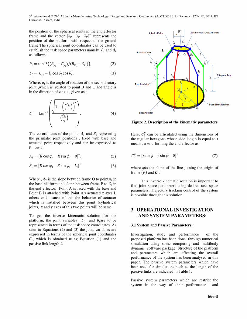
Table 2. Description of the task space variables
(distance in meter and angles in degree)
Pose � ! " # $ %
1. 0 0 1.5 10 10 10
2. 0.08 0.06 1.2 -5 -10 -5
3. 0.12 -0.18 1.4 10 13 30
4. 0.06 0.055 1.3 2 0 0
4. RESULTS AND DISCUSSION
In the previous section ,CRS platform structure and
its close form solution discussed. Analytical and
numerical simulation have been performed using
ADAMS (Multibody software package) and
MATLAB to validate the closed form solution.Same
passive parameters and known values have been
considered , in the ADAMS and MATLAB software
for the purpose of simulation. For the given known
initial values , simulation were performed wherein
the task space variables was given and the
performance of the closed form solution was
compared to get the accuracy of the solution. Virtual
prototyping of the platform using ADAMS imitate
the real conditions to a satisfactory extent the results
so obtained on performing analysis using this model
can be considered reliable and can hence be used to
assert for the performance of the inverse kinematic
solution proposed.
In the figure 3 and figure 4 , the pose of the end
effector has been presented and compared the joint
space variables obtained for the different task space
parameters. The accuracy and the precision of the
inverse kinematic solution can be appreciated from
the comparison.
The performance of the proposed solution is
reasonably close to that of the multibody simulated
model. The effectiveness of the solution guarantees
the usage of the proposed solution for dynamic
modelling of the platform and task-space controller
design without any erroneous interpretation of the
platform dynamics or kinematics.
5th International & 26th All India Manufacturing Technology, Design and Research Conference (AIMTDR 2014) December 12
Guwahati, Assam, India
(a)
(b)
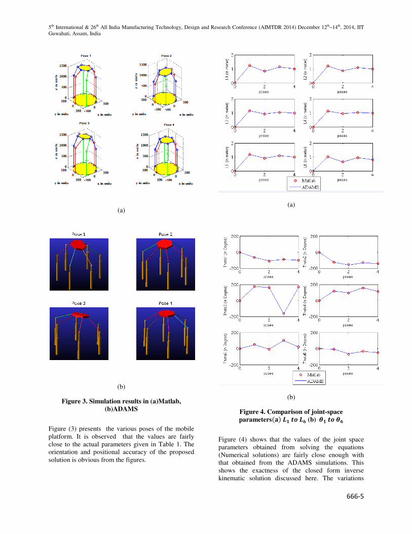
Figure 3. Simulation results in (a)Matlab,
(b)ADAMS
Figure (3) presents the various poses of the
platform. It is observed that the values are
close to the actual parameters given in Table 1. The
orientation and positional accuracy of the proposed
solution is obvious from the figures.
All India Manufacturing Technology, Design and Research Conference (AIMTDR 2014) December 12
Figure 3. Simulation results in (a)Matlab,
Figure (3) presents the various poses of the mobile
It is observed that the values are fairly
close to the actual parameters given in Table 1. The
orientation and positional accuracy of the proposed
(a)
(b)
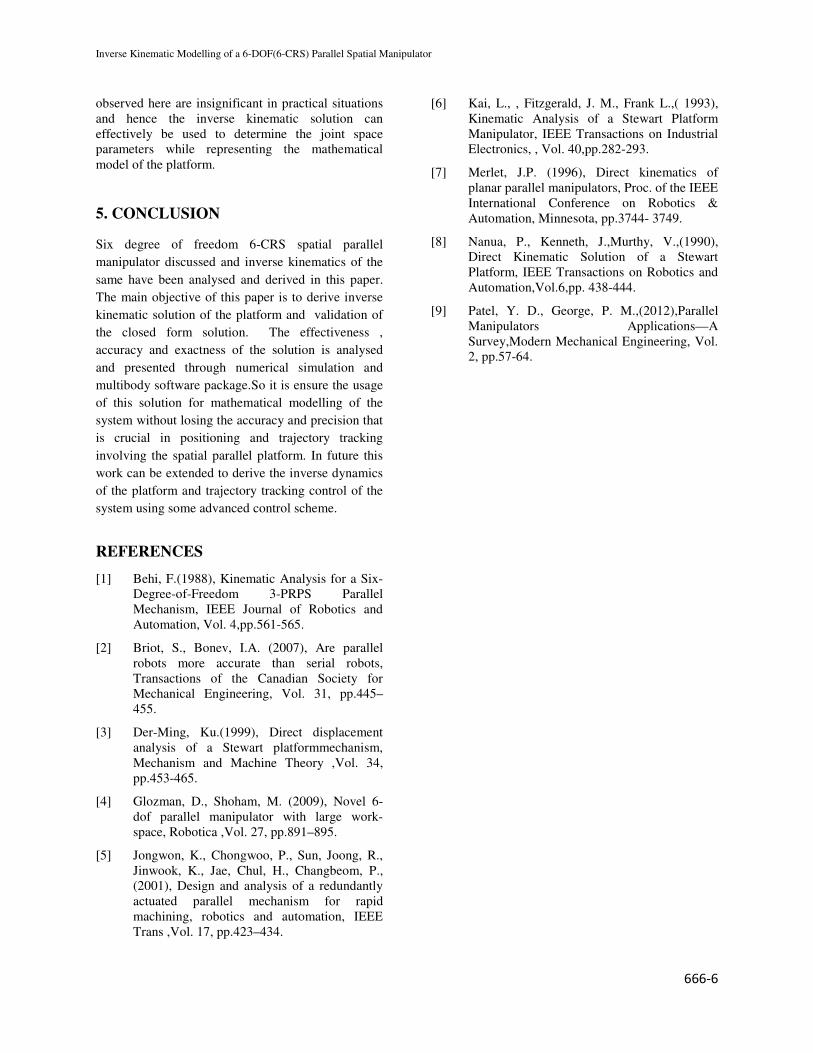
Figure 4. Comparison of joint
parameters(Y) Z[ \] Z^ (b)
Figure (4) shows that the values of the joint space
parameters obtained from solvin
(Numerical solutions) are fairly
that obtained from the ADAMS
shows the exactness of the closed form inverse
kinematic solution discussed here. The variations
All India Manufacturing Technology, Design and Research Conference (AIMTDR 2014) December 12th–14th, 2014, IIT
666-5
Figure 4. Comparison of joint-space
(b) _[ \] _^
shows that the values of the joint space
parameters obtained from solving the equations
close enough with
ADAMS simulations. This
shows the exactness of the closed form inverse
ussed here. The variations
Inverse Kinematic Modelling of a 6-DOF(6-CRS) Parallel Spatial Manipulator
666-6
observed here are insignificant in practical situations
and hence the inverse kinematic solution can
effectively be used to determine the joint space
parameters while representing the mathematical
model of the platform.
5. CONCLUSION
Six degree of freedom 6-CRS spatial parallel
manipulator discussed and inverse kinematics of the
same have been analysed and derived in this paper.
The main objective of this paper is to derive inverse
kinematic solution of the platform and validation of
the closed form solution. The effectiveness ,
accuracy and exactness of the solution is analysed
and presented through numerical simulation and
multibody software package.So it is ensure the usage
of this solution for mathematical modelling of the
system without losing the accuracy and precision that
is crucial in positioning and trajectory tracking
involving the spatial parallel platform. In future this
work can be extended to derive the inverse dynamics
of the platform and trajectory tracking control of the
system using some advanced control scheme.
REFERENCES
[1] Behi, F.(1988), Kinematic Analysis for a Six-
Degree-of-Freedom 3-PRPS Parallel
Mechanism, IEEE Journal of Robotics and
Automation, Vol. 4,pp.561-565.
[2] Briot, S., Bonev, I.A. (2007), Are parallel
robots more accurate than serial robots,
Transactions of the Canadian Society for
Mechanical Engineering, Vol. 31, pp.445–
455.
[3] Der-Ming, Ku.(1999), Direct displacement
analysis of a Stewart platformmechanism,
Mechanism and Machine Theory ,Vol. 34,
pp.453-465.
[4] Glozman, D., Shoham, M. (2009), Novel 6-
dof parallel manipulator with large work-
space, Robotica ,Vol. 27, pp.891–895.
[5] Jongwon, K., Chongwoo, P., Sun, Joong, R.,
Jinwook, K., Jae, Chul, H., Changbeom, P.,
(2001), Design and analysis of a redundantly
actuated parallel mechanism for rapid
machining, robotics and automation, IEEE
Trans ,Vol. 17, pp.423–434.
[6] Kai, L., , Fitzgerald, J. M., Frank L.,( 1993),
Kinematic Analysis of a Stewart Platform
Manipulator, IEEE Transactions on Industrial
Electronics, , Vol. 40,pp.282-293.
[7] Merlet, J.P. (1996), Direct kinematics of
planar parallel manipulators, Proc. of the IEEE
International Conference on Robotics &
Automation, Minnesota, pp.3744- 3749.
[8] Nanua, P., Kenneth, J.,Murthy, V.,(1990),
Direct Kinematic Solution of a Stewart
Platform, IEEE Transactions on Robotics and
Automation,Vol.6,pp. 438-444.
[9] Patel, Y. D., George, P. M.,(2012),Parallel
Manipulators Applications—A
Survey,Modern Mechanical Engineering, Vol.
2, pp.57-64.


![Kinematic Analysis of A 3-DOF Parallel Mechanism for ... · dance with the Kutzbach-Gruebler criterion [2], λ=6, n=8, ... Kinematic Analysis of A 3-DOF Parallel Mechanism for Milling](https://img.pdfslide.net/doc/110x75/5b1c01a67f8b9a46258f3522/kinematic-analysis-of-a-3-dof-parallel-mechanism-for-dance-with-the-kutzbach-gruebler.jpg)

![Imposing Joint Kinematic Constraints with an Upper Limb ...vigir.missouri.edu/~gdesouza/Research/Conference... · the 7-DOF Soft-actuated exoskeleton [15] used pneumatic muscles](https://img.pdfslide.net/doc/110x75/5f7bfcb6d00b511cb17777fa/imposing-joint-kinematic-constraints-with-an-upper-limb-vigir-gdesouzaresearchconference.jpg)