Embed Size (px)
Citation preview

INVERTER PACKAGEDAIR-CONDITIONER
08P01E-B-0(revision)
For a better tomorrow
High performance Air conditioner
�����
50/60Hz

1
New Inverter SeriesNew Inverter Series
Thanks to achievement of the highestCOP level in the industry, the energy consumption has been cut by 30~49% compared with our former models (constant speed models).
Industry Leading COPIndustry Leading COP
All models employ R410A, with RoHS* directiveAll models employ R410A, with RoHS* directiveRoHS *RoHS : Restriction of Hazardous Substances�����
AB
C
DE
F
G
CLASSAAA
MHI models have cleared the class A standard, the highest energy saving level, with their high COP (coefficient of performance).
Energy labeling“Class A”
Wide range of operation
except FDC71VN: -10°C50403020100-10-20
Heating
Cooling +43°C
+24°C
-15°C
-15°C *Heating and cooling operation at -15°COur new advanced technology has expanded the heating and cooling operation range.This permits installation of the units considering a heating and cooling operation under a low outdoor temperature conditions down to -15°C.
Achieved COP 5.67based on 50% capacity of FDT100V (inverter model) in heating operation
Air-conditioners are generally selected with the operation under the most severe ambient temperature conditions.The inverter constantly adjusts compressor output to meet the exact demand of the indoor units.
i.e. In case that selecting the capacity of an inverter air-conditioner based on heating operation at -5°C, its capacity drops by 50% at 7°C(ISO-TI measurement condition) and operation period at 50% capacity is normally longer than that at 100% of nominal heating capacity.
Considering annual electrical power consumption of inverter air-conditioners, it is quite important to give the first priority to 50% actual capacity and selecting inverter air-conditioners is the best solution for saving energy and protecting the environment.
Applying nonpolar 2-core in new remote control line, it is very convenient for installation including renewal case.
Current New
�-core �-core�-core
New remote control for all indoor units

2
�����LINE-UP
INDOOR UNIT
OUTDOOR UNIT
WIRED REMOTE CONTROL
SUPER LINK- Control System
OUTDOOR UNIT Dimensions
5
9
19
20
21
23
A
-core
High efficiency
According to room temperature conditions, four directions of air flow can be controlled by individual flap as preferred. As individual flap control is available even after installation, installation area became wider than before.
Due to optimization of outlet design of air flow with our new advanced technology, sufficient air flow is secured and long reach of air flow is realized. Current New
Individual flap control system
SRC50/60ZHX-S is common for both of outdoor units of SRK50/60ZHX-S and 1.5, 2, 2.5HP of Inverter Packaged Air-Conditioners. Common components make for easy inventory control and the installation procedure will be the same.
New outdoor units SRC50/60ZHX-S
Thanks to new design of heat exchanger changed from 2 parts to 1 part, the height of indoor unit is reduced drastically.
Furthermore applying DC fan motors, the highest energy efficiency level, reduction of weight and significant compact design are realized.
The thinnest design
Expansion of outlet air flow area realizes reduction of pressure loss caused by air flow in the indoor unit. Load of fan motor is decreased and efficiency is increased.
• Reduction of air flow pressure loss
• Increase of heat transfer efficiency
Current New
Shape of Heat exchanger
270mm
246mm
FDT40~71
9%reduction!!
365mm
298mm
FDT125~140
18%reduction!!
Applying high efficient piping in heat exchanger and optimization of heat exchanger (2parts 1part) increases heat transfer efficiency.

3
Compact Design
Size reduction and high efficiencyperformance on the DC twin rotary compressor(4-6HP)
Improved efficiency of heat exchanger
Employment of DC fan motor has enabled to realize an excellent
efficiency of approx. 60% higher than former models.
Employment of DC fan motor
Reliability in the protection of compressor has been improved by
optimizing the controls of oil return, electronic expansion valve, etc.
ControllabilityA control over wide range of capacity and a high efficiency has been realized by inverter-driven scroll compressors.In addition, the starting current significantly is improved.The size has also been reduced by 3.2% in height and 31.8% in volume.
Employment of the inverter compressor(8/10HP)
Redesigning the fins to a straight shape has reduced the pressure loss of the airflow in the heat exchanger. Surface treatment on the fin has enhanced the frost resistance capacity compared with former models.Owing to the reduction in the size of heat exchanger, the appropriate number of circuits for each HP has been applied. Employment of a high-speed motor has increased the airflow and enabled to keep the cooling capacity under a condition of higher outdoor air temperatures*.
Former model New model
Heigh
t at 4
40 m
m
Outside diameter of shellø185mm
Hei
ght a
t 342
mm
Reduction in height by 22.3%Reduction in volume by 44.1%
Formercompressor
* Vector control means a. technique to realize an optimum control by converting the current wave to a smooth sinusoidal waveform
* Comparison with former models
�������� � ����� ���
Former model New model Reduction
82 74 -8118 74 -44125 74 -51225 122 -103225 140 -85
4.0HP
63 60 -33.0HP
5.0HP
6.0HP
8.0HP
10.0HP
* Comparison with former models
�������� � ������ ��
Former model New model Reduction
328 303 8%467 303 35%467 303 35%1643 467 72%1643 540 67%
4.0HP
5.0HP
6.0HP
8.0HP
10.0HP
253 224 11%3.0HP
Employment of DC twin rotary compressor has enabled to utilize a high-speed range of up to 120 rps at the maximum to secure the required capacity.Optimum compressor control has been realized by employing the vector control* and the starting current has been improved significantly compared with former models. Moreover, viblation has been reduced.
* Limitation of use is around43: at the maximum.
������� ������ ����� ��������� ��
FDC71VN (3.0HP) FDC100VN/VS (4.0HP)
FDC125VN/VS (5.0HP)
FDC140VN/VS (6.0HP)
FDC200VS (8.0HP) FDC250VS (10.0HP)
Width
380mm
185mm
380mm
350mm
390mm
455mmHeight
Height
Height Height
Width
Depth
350mmDepth
95mm
Easy installation Fits into elevators
New modelDC rotary compressor
ø133mm

4
Consideration on the Environment
All models of the New inverter series use a new refrigerant R410A characterized by the ozone depletion coefficient being 0.
In order to comply with RoHS standard, the new inverter series products use lead-free solder. It was considered to be too difficult to use lead-free solder because it requires higher soldering temperatures at assembling, which could jeopardize the reliability of assembly, etc. PbF soldering method developed by MHI, however, has enabled a higher reliability for lead-free printed circuit boards.*"RoHS" is the abbreviation of the new European standard, which means reduction of hazardous substances.
Employment of lead-free solder
FDC200VS (8.0HP)
DC fan motor uses less energyPOINT1
Optimization of heat exchanger path.More efficient heating and cooling
POINT2
Super heat control with low pressure sensor, works better in tough conditions
POINT3
High efficiency refrigeration circuitPOINT4
Newly developed High efficiency DC scroll compressor
POINT5
970mm370mm
1
2
3
5
4
High EfficiencyNew Inverter Technology means a 30~49% decrease in annual energy consumption.
Employment of the new refrigerant
A High Performance and Excellent Energy Conservation are achieved at the same time by an increased capacity of heat exchanger and employment of high efficiency DC motor etc.
Energy Conservation
Adapt to RoHS
ConvenienceA dry contact is equipped on an indoor unit to meet a possible need for signal output on the site.
Installation workability (8&10HP)Using piping attachment that has flared connection and brazed connection ends, there is no need conduct brazing work inside the outdoor unit.
XR5
CnT
XR1~5 : approx. DC12v
XR3
XR1
XR2
XR4
XR5
XR1
XR2
XR3
XR4
output1 (run)
output2 (heat)
output3 (comp on)
output4 (alarm)
common
Po
wer
sou
rce
in put
Flaredconnection
Brazedconnection
���� ����������� ���� ��� ���� ���������
232mm
10.0HPCalculation condition: based on JRA4048 place: Tokyo, type of the room: shop
8.0HP6.0HP4.0HP3.0HP0
5000
10000
15000 -30%
-37%
-41%-44%
-39%
Former modelNew model
12531.4
10307.5
7193.56510.9
3528.3
8827
6461
42733693
2149
5.0HP
-49%
5268.5
2673
[kWp/year]
5
SINGLE [OUTDOOR UNIT : INDOOR UNIT = 1 : 1]
�������
������
�� �
����
��
���� ��� ��� ���� � ������
���
�������� � ������ !�""#!�
���
$�%& ������ !�""#!�
��
��
�������
�'������
���
�(������
Indoorunit
Outdoorunit
Indoorunit
Outdoorunit
Indoorunit
Outdoorunit
Indoorunit
Outdoorunit
Indoorunit
Outdoorunit
Set1phase
1phase
1phase
3phase
1phase3phase1phase
1phase
1phase
3phase
1phase3phase1phase3phase
1phase3phase
1.5
FDT40V
����)$*+ ��,�)$*+ ����)$*+
FDT50V FDT60V
Set
FDTC40V
�����)$*+ ���,�)$*+
FDTC50V
Set
Set���,�)$*+ �����)$*+
3phase
FDUM50V FDUM60V
Set
FDEN40V
�����)$*+ ���,�)$*+ �����)$*+
SRC40ZHX-S SRC50ZHX-S SRC60ZHX-S
SRC40ZHX-S SRC50ZHX-S
SRC50ZHX-S SRC60ZHX-S3phase
SRC40ZHX-S SRC50ZHX-S SRC60ZHX-S
FDEN50V FDEN60V
HPkWBtukcal
2.0 2.54.0
13,7003,440
5.017,1004,300
6.019,1004,816
�� �����
NEW
NEW
NEW
NEW
NEW

6
��-.+�+
FDT71V FDT100V FDT125V FDT140V
*��-.+�+ *��.��+�+ *��./,+�+ *��.��+�+
*��.��+�+ *��./,+�+ *��.��+�+ ��/��+�+ ��/,�+�+
FDU71V FDU100V FDU125V FDU140V FDU200V FDU250V
���-.+�+ ���.��+�+ ���./,+�+ ���.��+�+
���.��+�+ ���./,+�+ ���.��+�+
FDUM71V FDUM100V FDUM125V FDUM140V
���-.+�+ ���.��+�+ ���./,+�+ ���.��+�+
���.��+�+ ���./,+�+ ���.��+�+
FDC71VNFDC100VS FDC125VS FDC140VSFDC100VN FDC125VN FDC140VN
FDC71VN FDC100VN FDC125VN FDC140VNFDC100VS FDC125VS FDC140VS FDC200VS FDC250VS
FDC71VN FDC100VN FDC125VN FDC140VNFDC100VS FDC125VS FDC140VS
FDC71VNFDC100VS FDC125VS FDC140VSFDC100VN FDC125VN FDC140VN
FDEN71V FDEN100V FDEN125V FDEN140V
3.0 4.0 5.0 6.0 8.0 10.0 7.1
23,9006,020
10.034,1008,600
12.542,70010,750
14.047,80012,040
20.068,30017,200
25.085,40021,500
0�1%� �0���� ��� �1% �� ������
��.��+�+ ��./,+�+ ��.��+�+
��.��+�+ ��./,+�+ ��.��+�+
*Not available in 60Hz
NEW NEW
NEW NEW

7
MULTI [OUTDOOR UNIT : INDOOR UNIT = 1 : 2, 3, 4] - V MULTI SYSTEM
����
���
����
���
��
���� �
Indoorunit
BranchPipe
TwinTripleDouble TwinTwinTripleDouble Twin
40 x 2
DIS-WA1
50 x 2
DIS-WA1
60 x 2, 50+71
DIS-WA1
FDC71VNFDC125VNFDC125VS
FDC100VNFDC100VS
Outdoor unit
HPkWBtukcal
3.07.1
23,9006,020
4.010.0
34,1008,600
5.012.5
42,70010,750
��������
Different models and capacities (FDT/FDUM/FDE: 40~125) can be selected freely.Exception : In case of FDTC, FDKNA:151~251 which are equivalent to 40~60 series are selected, same model and capacity combination is required.
� ���� ������ ��� ��� ��� ������ !� "
Outdoor unit
Indoor unit
Liquid line
Gas line
39 190
1019
ID25.4
ID15.88
ID15.88
ID9.52
ID9.52
ID9.52
OD12.7 ID9.52
12
80
184
8
8010
Diagrams below show the application as samples. For further information, please refer to TECHNICAL MANUAL.
Decision of piping specification
Outdoor unit
FDC71FDC100FDC125FDC140
40+4050+5060+6071+71
Indoor unit
Liquid line
Gas line
(Example)
24 210
8105
50811
ID15.88
ID15.88
ID15.88
ID9.52
ID9.52
ID9.52
ID9.52
OD15.88
2 piece 2 piece
ID12.7φ6.35 flared nut
11
48
180
8
8010
Models FDC71~140[Branch pipe set : DIS-WA1]
If you are using this model in combination with the 40 ~ 60 Series indoor units, use the irregular fittings 3 supplied with the branch piping set and make the branch piping (branch ~ indoor unit) liquid piping size 9.52.Mark is 4 to FDC71, 100 only.
Chart of shapes of branch piping parts (DIS-WA1)
Item Liquid pipe
Main pipeModelIndoor unit
combinations
Gas pipe Mark
1
Liquid pipe Reducer Mark
3
ReducerMark
2
Mark
4
1 to 4 in the drawing include parts provided in the branch piping set. It shows the codes for the shapes of different-diameter connections.Branch piping should always be arranged to have level or perpendicular branch. (Refer to the preceding page for details.)
Notes (1)
(2)
Branch pipe
Gas pipe
Main pipe Branch pipe
Notes (1)
(2)
9.52X t0.8 9.52X t0.812.7X t0.8
15.88X t1.015.88X t1.0
FDC200
FDC250
100+100
125+125
(Example)Models FDC200, 250[Branch pipe set : DIS-WB1]
Chart of shapes of branch piping parts (DIS-WB1)
Item Liquid pipe
Main pipeModelIndoor unit
combinations
1 to 3 in the drawing include parts provided in the branch piping set. It shows the codes for the shapes of different-diameter connections.Branch piping should always be arranged to have level or perpendicular branch. (Refer to the preceding page for details.)
Notes (1)
(2)
Branch pipe
Gas pipe
Main pipe Branch pipe
Notes (1)
9.52X t0.8
12.7X t0.89.52X t0.8 25.4X t0.8 15.88X t1.0
Gas pipe Mark
1
Liquid pipe Mark
2
Reducer Mark
3
2-Way Branch
FloorFloorMount sections levelwith the floor.
Floor
Mount sections perpendicular to the floor.
Floor
3-Way Branch
FloorMount sections levelwith the floor.
Floor
Mount sections perpendicular to the floor.
23
1
23
3
4
4
1
In the case of the FDC200, if the length of the main pipe exceeds 40 m, make the liquid piping size 12.7.
Up to four individual indoor units can be connected toa single outdoor unit.
V Multi System
Ideal for the installation in Large, single zone open Areas and L-shaped rooms, the Multi-
Type V series allows an extensive degree of flexibility in the selection of indoor units.
Specifically, the selection of indoor units with differing capacities and differing or similar
types is available, as is the selection of indoor units with similar capacities and differing
types. Furthermore, a maximum of up to four individual indoor units can be operated with
a single outdoor unit.
Twin
typ
e
The branch piping (both gas and liquid lines) should always be arranged to have a level or perpendicular branch.
*only used with V multi outdoor units

8
Combination in the table can be operated at 50/60Hz.
71 x 250+50+50 *1
DIS-WA1DIS-TA1 or DIS-WA1 x 2 *1
100 x 2, 71+12571 x 3 *2
50+50+50+50DIS-WB1
DIS-TB1 or DIS-WA1+DIS-WB1 *2
DIS-WA1 x 2, DIS-WB1 x 1
125 x 260+60+125, 71+71+100 *3
60+60+60+60DIS-WB1
DIS-WA1+DIS-WB1 *3
DIS-WA1 x 2, DIS-WB1 x 1
FDC140VNFDC140VS FDC200VS FDC250VS
6.014.0
47,80012,040
8.020.0
68,30017,200
10.025.0
85,40021,500
����� �������� ���������
Chart of shapes of branch piping parts (DIS-TB1)
Outdoor unit
Indoor unit
Liquid line
Gas line
Outdoor unit
Indoor unit100 80 80
10
300
ID9.52
ID25.4
ID15.88×3 ID9.52×3100
10 14˚
100
8 8
217
8
3030
Liquid line
Gas line
8105
50
ID9.52φ6.35Flared nut
OD12.7 ID9.52
8010
OD15.88 ID12.7
8010
Model FDC140 [Branch pipe set : DIS-TA1]
Model FDC200[Branch pipe set : DIS-TB1]
Chart of shapes of branch piping parts (DIS-WB1)
Gas pipe Liquid pipe ReducerMark Mark Mark
39 190
1019
ID25.4
ID15.88
ID15.88
ID9.52
ID9.52
ID9.52
OD12.7 ID9.51
11
80
184
8
8010
Chart of shapes of branch piping parts (DIS-WA1)
Gas pipe Liquid pipe ReducerMark Mark Mark
24 210
8105
50
811
ID15.88
ID15.88
ID15.88
ID9.52
ID9.52
ID9.52 ID9.52
OD15.88 ID12.7
2 piece
2 piece
φ6.35 flared nut
11
48
180
8
8010
5
1 to 7 in the drawing include parts provided in the branch piping set. It shows the codes for the shapes of different-diameter connections.Branch piping should always be arranged to have level or perpendicular branch. Mark 3 shows for the FDC200 model only.
Item Liquid pipe
Main pipe 1st branch pipe 2nd branch pipe
9.52X t0.8
12.7X t0.89.52X t0.8
Main pipe 1st branch pipe 2nd branch pipe
Gas pipe
ModelFDC200
FDC250
In the case of the FDC200, if the length of the main pipe exceeds 40 m, make the liquid piping size 12.7.Use the irregular fittings 6 supplied with the branch piping set on the indoor unit side, and make the branch piping (branch ~ indoor unit) liquid piping size 9.52.Mark is 7 to FDC200 only.
Notes (1)(2)
(3)
Notes (1)(2)(3)
Indoor unitcombinations
50+50+50+50
60+60+60+60
Item Liquid pipe
Main pipeModel
FDC200
Indoor unitcombinations
71+71+71
Outdoor unit
Indoor unitDIS-WA1
DIS-WA1
DIS-WB1
Gas line
Liquid line
6
Models FDC200, 250 [Branch pipe set : DIS-WA1x2set, DIS-WB1x1set]
4321
6
7
Gas pipe Mark
1
Liquid pipe Mark
2
Reducer Mark
-
Reducer Mark
-
Reducer Mark
-
1 to 2 in the drawing include parts provided in the branch piping set. It shows the codes for the shapes of different-diameter connections.Branch piping should always be arranged to have level or perpendicular branch. (Refer to the preceding page for details.)
Notes (1)
(2)
9.52X t0.8 15.88X t1.015.88X t1.0
12.7X t0.825.4X t1.0
6
6
6
5
5
7
7
7
4
7
4
23
1
9.52X t0.8 9.52X t0.8
Branch pipe
Gas pipe
Main pipe
25.4X t1.0 15.88X t0.8
Branch pipe
Notes (1) If the length of the main pipe exceeds 40 m, make the liquid piping size 12.7.
Chart of shapes of branch piping parts (DIS-TA1)
100 80 80
8105
5010
300
ID9.52
ID15.88
ID12.7×3 ID9.52×3
ID9.52φ6.35Flared nut
10 14˚
100
8
237
8
3030
Item Liquid pipe
Main pipeModel
FDC140
Indoor unitcombinations
50+50+50
Gas pipe Mark
1
Liquid pipe Mark
2
Reducer Mark
3
1 to 3 in the drawing include parts provided in the branch piping set. It shows the codes for the shapes of different-diameter connections.Branch piping should always be arranged to have level or perpendicular branch. (Refer to the preceding page for details.)
Notes (1)
(2)
9.52X t0.8 9.52X t0.8
Branch pipe
Gas pipe
Main pipe
15.88X t1.0 12.7X t0.8
Branch pipe
Use the irregular fittings 3 supplied with the branch piping set on the indoor unit side, and make the branch piping (branch ~ indoor unit) liquid piping size 9.52.
Notes (1)
ID25.4 ID22.2 OD25.4 ID22.2
A B
This kit includes the following parts.
Install this kit according to the following.
(*) ID: Inner diameter.
Applicable outdoor models
FDC200
FDC250
Installation manual for pipe size reducer kit 22.2 (OD) size of the refrigerant gas pipe can be used by using this kit, although 25.4 (OD) size of the refrigerant gas pipe is standard.(When 25.4 (OD) size of the refrigerant gas pipe is used, this kit doesn't be needed.)(*) OD: Outer diameter.
2
1
2
3
3
31
Trip
le t
ype
Do
ub
le t
win
typ
e
3 piece
2 piece 2 piece 1 piece
Field piping φ22.2(OD) Branching pipe set (DIS-WB1, DIS-TB1)
Brazing
Accessory pipe A Accessory pipe B
In case of V-multi
Indoor units connected to the same outdoor unit must be installed under the same operation conditions in the same room. If the operation conditions of any indoor units are different, there might be shortage of capacity. All indoor units must be controlled by single remote control.
*1 When the length differences among piping running between the outdoor unit and indoor units are less than 3m, DIS-TA1 is required. When the difference is 3m or more, DIS-WA1x2 pieces are required.
*2 When the length differences among piping running between the outdoor unit and indoor units are less than 3m, DIS-TB1 is required. When the difference is 3m or more, DIS-WA1 and DIS-WB1 are required.
*3 The length differences among piping running between the outdoor unit and the indoor units must be less than 3m.
9
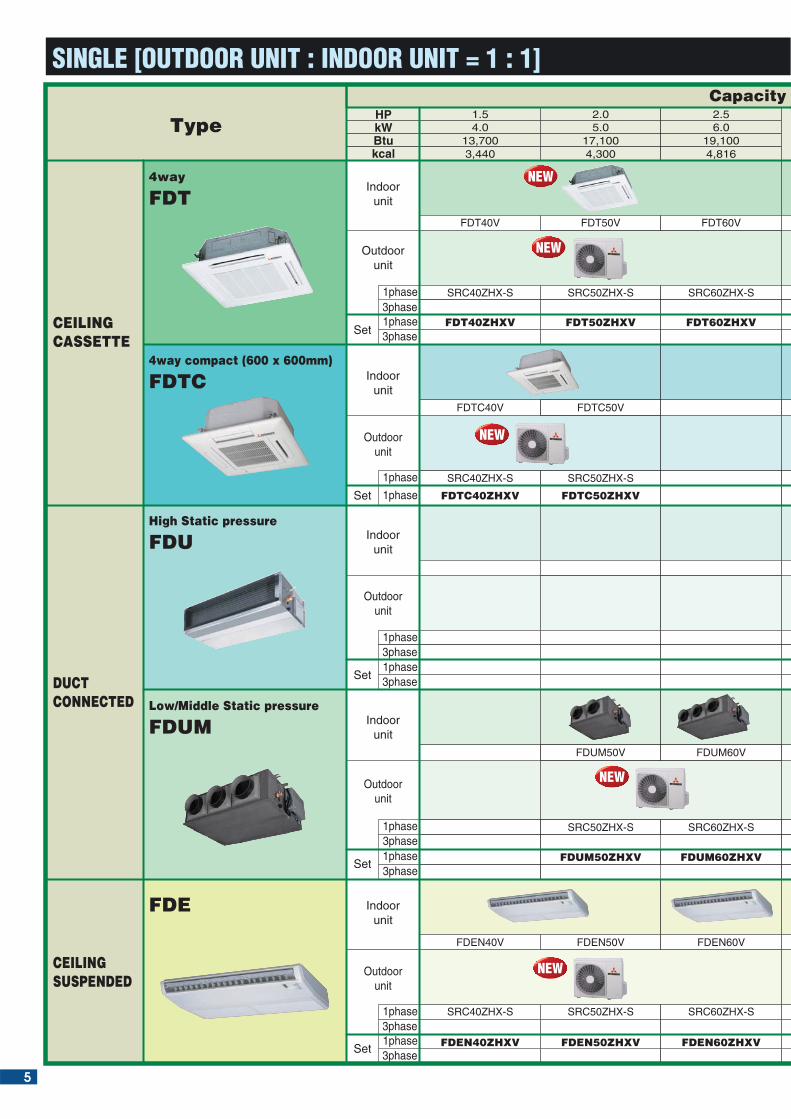
FDT FDT 40/50/60/71/ 100/125/140V
INDOOR UNIT
CEILING CASSETTE -4way-
Outline drawing (Unit:mm)
�����
RCN-T-36W-E(Option)
CLASSAAA
RC-E3(Option)
Point
1 Arrangement of installation balance of indoor unitChecking from access ports with
detachable covers at each corner,
arrangement of installation balance of
indoor unit can be available without
removing a panel. Workability is
improved and time of installation is
reduced.
Wireless remote control Wired remote control
RCN-T-36W-E
For wireless control simply insert the infra-red receiver kit on a corner of the panel
wireless remote control
Model 100,125,140VModel FDT40,50,60,71V
NEW
10
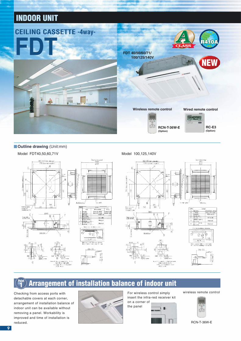
AEasy checking of drain
pan condition is available
by removing corner lid
only. Due to new design
changing fan motor is
available without removing
a panel. Temporally
setting of drain pan is also
availlable.
Point
2 Easy checking of drain pan
Drain can be discharged upwards by 700mm from
the ceiling surface. It allows a piping layout with a
high degree of freedom Depending on the installation
location and 260mm
flexible hose as a
standard equipment
supports easy
workability.
3phase,380-415V 50Hz/380V 60Hz
Point
3 700mm Drain Pump
kW
kW
kW
A
dB(A)
CMM
mmmmkg
mmkg
kg(m)ø
m<O/U>O/UI/UO/UI/UO/U
1Phase 220-240V 50Hz ,1Phase 220V 60Hz
Inverter
FDT71VNVFDT71V
FDC71VN
FDT100VNVFDT100V
FDC100VN
FDT125VNVFDT125V
FDC125VN
Cooling:75 Heating:73
7.1(3.2~8.0)
8.0(3.6~9.0)
1.90/2.073.74/3.86
A/A
2.95(30)
-10~24
Hi:35 Me:33 Lo:3148
Hi:21 Me:19 Lo:17Cooling:60 Heating:50246x840x840
24+5.5
750x880(+88)x34060
10.0(4.0~11.2)
11.2(4.0~12.5)
2.76/2.743.62/4.09
A/A
Hi:40 Me:37 Lo:3549
Hi:27 Me:24 Lo:20Cooling:76 Heating:74
12.5(5.0~14.0)
14.0(4.0~16.0)
4.05/3.773.09/3.71
B/A
Hi:42 Me:40 Lo:37Cooling:50 Heating:51Hi:30 Me:27 Lo:23
14.0(5.0~14.5)
16.0(4.0~16.5)
4.98/4.572.81/3.50
C/B5
Hi:43 Me:41 Lo:3851
Hi:30 Me:27 Lo:23
35x950x950
T-PSA-36W-E+RCN-T-36W-E, T-PSA-36W-E+RC-E3
RotaryEEV
9.52/15.88503015
18~30-15~43*2
18~30-15~24
SPECIFICATIONS
Indo
or u
nit
Outd
oor
unit
Ran
ge o
fus
age
Lim
itatio
ns
The data are measured under the following conditions(ISO-T1).Cooling:Indoor temp. of 27˚CDB, 19˚CWB, and outdoor temp. of 35˚CDB. Heating:Indoor temp. of 20˚CDB, and outdoor temp. of 7˚CDB, 6˚CWB.
*1 : Indicates the value in an anechoic chamber. During operation these values are somewhat higher due to ambient conditions.
*2 : If a cooling operation is conducted when the outdoor air temperature is –5˚C or lower, the outdoor unit should be installed at a place where it is not influenced by natural wind. If wind blows, the low pressure will drop and compressor frequency will increase, this will cause the capacity to drop and may cause the unit to break down.
Set model nameIndoor nameOutdoor name
Power source
TypeNominal cooling capacity (Min~Max)Nominal heating capacity (Min~Max)InputCOPEnergy labelInrush current
Sound Ievel*1
Air flow
Exterior dimensionsPanelNet weightPanel+Remote controlExterior dimensionsNet weightType of compressorRef.controlRef.amount prechargedRef.piping size Ref.piping length Vertical height difference
Air temp.
ISO-T1(JIS)
ISO-T1(JIS)
Cooling/HeatingCooling/HeatingCooling/Heating
IndoorOutdoorIndoorOutdoorHeight x Width x DepthHeight x Width x DepthUnit+Panel
Height x Width x Depth
Liquid/Gas
between O/Uand I/U
Cooling
Heating
kW
kW
kW
A
dB(A)
CMM
mmmmkg
mmkg
kg(m)ø
m<O/U>O/UI/UO/UI/UO/U
FDT40ZHXVFDT40V
SRC40ZHX-S
47
22+5.5
FDT50ZHXVFDT50V
SRC50ZHX-S
1Phase 220-240V 50Hz ,1Phase 220V 60Hz
Inverter
FDT60ZHXVFDT60V
SRC60ZHX-S
4.0(1.8~4.7)
4.5(2.0~5.4)
0.93/1.154.30/3.91
A/A
5.0(2.2~5.6)
5.4(2.5~6.3)
1.29/1.293.88/4.19
A/A5
Hi:33 Me:31 Lo:30
Hi:18 Me:16 Lo:1440
246x840x84035x950x950
T-PSA-36W-E+RCN-T-36W-E, T-PSA-36W-E+RC-E3640x800(+71)x290
45ScrollEEV
1.4(15)6.35/12.7
302020
18~30-15~43*2
18~30-15~24
5.6(2.8~6.3)
6.7(3.1~7.1)
1.57/1.853.57/3.62
A/A
48
24+5.5
SPECIFICATIONS
Indo
or u
nit
Outd
oor
unit
Ran
ge o
fus
age
Lim
itatio
ns
FDT100VSVFDT100V
FDC100VS
FDT125VSVFDT125V
FDC125VS
FDT140VSVFDT140V
FDC140VS
FDT140VNVFDT140V
FDC140VN
10.0(4.0~11.2)
11.2(4.0~12.5)
2.76/2.743.62/4.09
A/A
Hi:40 Me:37 Lo:3549
Hi:27 Me:24 Lo:20Cooling:76 Heating:74
12.5(5.0~14.0)
14.0(4.0~16.0)
4.05/3.773.09/3.71
B/A
Hi:42 Me:40 Lo:37Cooling:50 Heating:51Hi:30 Me:27 Lo:23
14.0(5.0~14.5)
16.0(4.0~16.5)
4.98/4.572.81/3.50
C/B
Hi:43 Me:41 Lo:3851
Hi:30 Me:27 Lo:23Cooling:75 Heating:73
298x840x840
27+5.5
845x970x37074
3.8(30)
Flexible hose
less than 700mm
Set model nameIndoor nameOutdoor name
Power source
TypeNominal cooling capacity (Min~Max)Nominal heating capacity (Min~Max)InputCOPEnergy labelInrush current
Sound Ievel*1
Air flow
Exterior dimensionsPanelNet weightPanel+Remote controlExterior dimensionsNet weightType of compressorRef.controlRef.amount prechargedRef.piping size Ref.piping length Vertical height difference
Air temp.
ISO-T1(JIS)
ISO-T1(JIS)
Cooling/HeatingCooling/HeatingCooling/Heating
IndoorOutdoorIndoorOutdoorHeight x Width x DepthHeight x Width x DepthUnit+Panel
Height x Width x Depth
Liquid/Gas
between O/Uand I/U
Cooling
Heating

11
FDTC
FDTC 40/50V
�����
INDOOR UNIT
CEILING CASSETTE -4way Compact (600 X 600mm)-
RCN-TC-24W-ER(Option)
RC-E3(Option)
CLASSAAA
Outline drawing (Unit:mm)
Point
1 “CLEARER”AIR FLOW Point
2 INSTALLATION WORKABILITY
Wireless remote control Wired remote control
RCN-TC-24W-ER
New shape & angled louvre re-
directs the air current away from
the ceiling, to reduce ceiling stains
For wireless control simply insert
the infra-red receiver kit on a
corner of the panel
wireless remote control

12
A Point
3 Compact ConceptThe industry's lowest level 248mm height.Panel size (700x700) is suitable for 600x600 ceiling panel.
All indoor unit size is (WxD: 570x570). It brings easy installation for
600x600 ceiling panel.
Point
4 Comfortable and ConvenientWired remote control or Wireless remote
control can be selected.
All units are 18.5kg, light weight unit.
•
•
600mm Drain Pump is mounted.• New designed panel is developed exclusively for FDTC series.
•
Thanks to width and depth of exterior
dimensions of a indoor unit are 570mm
each, the installation work can be conducted
smoothly with a beautiful finishing in 2x2
ceiling size.
Drain can be discharged upward by 600 mm from the ceiling surface close to the indoor unit.It allows a piping layout with a high degree of freedom depending on the installation location.
•
Flexible hose
600mm
Set model nameIndoor nameOutdoor name
Power source
TypeNominal cooling capacity (Min~Max)Nominal heating capacity (Min~Max)InputCOPEnergy labelInrush current
Sound Ievel*1
Air flow
ISO-T1(JIS)
ISO-T1(JIS)
Cooling/HeatingCooling/HeatingCooling/Heating
IndoorOutdoorIndoorOutdoorHeight x Width x DepthHeight x Width x DepthUnit+Panel
Height x Width x Depth
Liquid/Gas
between O/Uand I/U
Cooling
Heating
kW
kW
kW
A
dB(A)
CMM
mmmmkg
mmkg
kg(m)ø
m<O/U>O/UI/UO/UI/UO/U
FDTC40ZHXVFDTC40V
SRC40ZHX-S
4.0(1.8~4.7)
4.5(2.0~5.4)
1.04/1.103.85/4.09
FDTC50ZHXVFDTC50V
SRC50ZHX-S
5.0(2.2~5.6)
5.4(2.5~6.3)
1.56/1.453.21/3.72
SPECIFICATIONS
Indo
or u
nit
Out
door
uni
t R
ange
of
usag
eLi
mita
tions
A/A5
Hi:42 Me:38 Lo:3547
Hi:11.5 Me:10 Lo:840
248x570x57035x700x700
15+3.5TC-PSA-24W-ER+RCN-TC-24W-ER, TC-PSA-24W-ER+RC-E3
640x800(+71)x29045
ScrollEEV
1.4(20)6.35/12.7
302020
18-30-15-43*2
18-30-15-24
1Phase 220-240V 50Hz ,1Phase 220V 60Hz
Inverter
The data are measured under the following conditions(ISO-T1).Cooling:Indoor temp. of 27˚CDB, 19˚CWB, and outdoor temp. of 35˚CDB. Heating:Indoor temp. of 20˚CDB, and outdoor temp. of 7˚CDB, 6˚CWB.
*1 : Indicates the value in an anechoic chamber. During operation these values are somewhat higher due to ambient conditions.
*2 : If a cooling operation is conducted when the outdoor air temperature is –5˚C or lower, the outdoor unit should be installed at a place where it is not influenced by natural wind. If wind blows, the low pressure will drop and compressor frequency will increase, this will cause the capacity to drop and may cause the unit to break down.
Exterior dimensionsPanelNet weightPanel+Remote controlExterior dimensionsNet weightType of compressorRef.controlRef.amount prechargedRef.piping size Ref.piping length Vertical height difference
Air temp.
248
Opening for exit wiringUltra slim design at just 248mm above the ceiling

13
Control box
Fan motorHigh static pressure silent fan
Slide type fan system
Thin type duct connection opening
Point
1 Enhanced installation workability Point
2 Adaptability to higher static pressures
This is a real and earnest model for duct air-conditioning. A unit external static pressure of up to 200 Pa (FDU200/250V) is possible. Precise air flow designing is possible.
High static pressure of 200 Pa (FDU200/250V) extends the degree of freedom in the designing of air conditioners.
Quiet, Lightweight and CompactWith the FDU71, the noise level is only 37dB (low), weight is only 40kg and height is only 297mm. In addition 600mm Drain Pump is mounted in FDU71/100/125/140V.The indoor unit is completely hidden in the ceiling, so this is suitable for spaces with classy interior decoration.
Outline drawing (Unit:mm)
INDOOR UNIT
�����CLASSAAA
FDU71/100/125/140V
FDUDUCT CONNECTED -High Static presure-
RC-E3(Option)
Wired remote control
FDU71V
FDU100,125,140V
FDU200,250V
FDU200/250V
NEW
Height297mm

ISO-T1(JIS)
ISO-T1(JIS)
Cooling/Heating
Cooling/Heating
Cooling/Heating
IndoorOutdoorIndoorOutdoor
Height x Width x Depth
Height x Width x Depth
Liquid/Gas
between O/Uand I/U
Cooling
Heating
kW
kW
kW
A
dB(A)
CMM
Pammkg
mmkg
kg(m)ø
m<O/U>O/UI/UO/UI/UO/U
SPECIFICATIONS
Indo
or u
nitO
utdo
or u
nit
Ran
ge o
fus
age
Lim
itatio
ns
FDU200VSVFDU200V
FDC200VS
FDU250VSVFDU250V
FDC250VS
20.0(7.0~22.4)
22.4(7.6~25.0)
50Hz:6.59/6.0860Hz:6.58/5.8450Hz:3.03/3.6860Hz:3.04/3.83
B/A
5157
50Hz:51, 60Hz:60
122
5.4(30)9.52/25.4
25.0(10.0~28.0)
28.0(9.5~31.5)
50Hz: 9.91/8.5060Hz:10.21/8.2250Hz:2.52/3.2960Hz:2.45/3.41
E/B
52Cooling:57 Heating:58
50Hz:68, 60Hz:80
140
7.2(30)12.7/25.4
3Phase,380-415V,50Hz,380V,60Hz
Inverter
5
Cooling:150 Heating:145standard:100, Max:200
360x1,570x83092
RC-E3
ScrollEEV
703015
18-30 -15-43 *2
18-30 -15-24
14
Set model nameIndoor nameOutdoor name
Power source
TypeNominal cooling capacity (Min~Max)Nominal heating capacity (Min~Max)InputCOPEnergy labelInrush current
Sound Ievel*1
Air flow
Static pressureExterior dimensionsNet weightRemote controlExterior dimensionsNet weightType of compressorRef.controlRef.amount prechargedRef.piping size Ref.piping length Vertical height difference
Air temp.
ISO-T1(JIS)
ISO-T1(JIS)
Cooling/HeatingCooling/HeatingCooling/Heating
IndoorOutdoorIndoorOutdoor
Height x Width x Depth
Height x Width x Depth
Liquid/Gas
between O/Uand I/U
Cooling
Heating
kW
kW
kW
A
dB(A)
CMM
Pammkg
mmkg
kg(m)ø
m<O/U>O/UI/UO/UI/UO/U
*FDU125VNVFDU125V
FDC125VN
*FDU140VNVFDU140V
FDC140VN
*FDU71VNVFDU71V
FDC71VN
SPECIFICATIONS
Indo
or u
nitO
utdo
or u
nit
Ran
ge o
fus
age
Lim
itatio
ns
1Phase 220-240V 50Hz
*FDU100VNVFDU100V
FDC100VN
*FDU100VSVFDU100V
FDC100VS
*FDU125VSVFDU125V
FDC125VS
3phase,380-415V 50Hz
*FDU140VSVFDU140V
FDC140VS
7.1(3.2~8.0)
8.0(3.6~9.0)
10.0(4.0~11.2)
11.2(4.0~12.5)
12.5(5.0~14.0)
14.0(4.0~16.0)
14.0(5.0~14.5)
16.0(4.0~16.5)
10.0(4.0~11.2)
11.2(4.0~12.5)
2.88/2.993.47/3.75
A/A
12.5(5.0~14.0)
14.0(4.0~16.0)
4.04/3.793.09/3.69
B/A
14.0(5.0~14.5)
16.0(4.0~16.5)
4.95/4.432.83/3.61
C/A
2.88/2.993.47/3.75
A/A
Hi:42 Lo:3749
Hi:34 Lo:27Cooling:76 Heating:74
4.04/3.793.09/3.69
B/A
Cooling:50 Heating:51
4.95/4.432.83/3.61
C/A5
51
standard:50, Max:130
RC-E3
RotaryEEV
9.52/15.88503015
18~30-15~43*2
18~30
Hi:42 Lo:3749
Hi:34 Lo:27Cooling:50 Heating:51 51
2.08/2.213.41/3.62
A/A
Hi:41 Lo:3748
Hi:25 Lo:20Cooling:60 Heating:50
297x850x65040
750x880(+88)x34060
2.95(30)
-10~24
Hi:43 Lo:38
Hi:42 Lo:33.5Cooling:75 Heating:73
Hi:43 Lo:38
Hi:42 Lo:33.5
845x970x37074
3.8(30)
-15~24
*Not available in 60Hz
The data are measured under the following conditions(ISO-T1).Cooling:Indoor temp. of 27˚CDB, 19˚CWB, and outdoor temp. of 35˚CDB. Heating:Indoor temp. of 20˚CDB, and outdoor temp. of 7˚CDB, 6˚CWB.
*1 : Indicates the value in an anechoic chamber. During operation these values are somewhat higher due to ambient conditions.
*2 : If a cooling operation is conducted when the outdoor air temperature is –5˚C or lower, the outdoor unit should be installed at a place where it is not influenced by natural wind. If wind blows, the low pressure will drop and compressor frequency will increase, this will cause the capacity to drop and may cause the unit to break down.
A
Set model nameIndoor nameOutdoor name
Power source
TypeNominal cooling capacity (Min~Max)Nominal heating capacity (Min~Max)
Input
COP
Energy labelInrush current
Sound Ievel*1
Air flow
Static pressureExterior dimensionsNet weightRemote controlExterior dimensionsNet weightType of compressorRef.controlRef.amount prechargedRef.piping size Ref.piping length Vertical height difference
Air temp.
350x1,370x65063
Cooling:76 Heating:74
1,300x970x370

Point
1 Various AdaptabilitySelectable static pressure and Flexible duct design with
selectable air suction (direct suction /duct suction) can
meet wide pattern of installation.
model
50/60/71V
100V
125/140V
Standard
50
60
60
Max
85
90
85
Drain can be discharged
upwards by 600mm from the
ceiling surface. It allows a
piping layout with a high
degree of freedom
Depending on the
installation location.
Point
2 600mm Drain Pump
Flexible hose
less than 600mm
Static pressure Pa
15
INDOOR UNIT
RC-E3 (Option)
Wired remote control
Outline drawing(Unit:mm)
Models FDUM60V,71VModel FDUM50V
�����CLASSAAAFDUM
FDUM 50/60/71/100/125/140V
DUCT CONNECTED -Middle Static pressure-

16
Outline drawing(Unit:mm)
Models FDUM100V,125V,140V
Set model nameIndoor nameOutdoor name
Power source
TypeNominal cooling capacity (Min~Max)Nominal heating capacity (Min~Max)
Input
COP
Energy labelInrush current
Sound Ievel*1
Air flow
Static pressureExterior dimensionsNet weightRemote controlExterior dimensionsNet weightType of compressorRef.controlRef.amount prechargedRef.piping size Ref.piping length Vertical height difference
Air temp.
ISO-T1(JIS)
ISO-T1(JIS)
Cooling/Heating
Cooling/Heating
Cooling/Heating
IndoorOutdoorIndoorOutdoor
Height x Width x Depth
Height x Width x Depth
Liquid/Gas
between O/Uand I/U
Cooling
Heating
kW
kW
kW
A
dB(A)
CMM
Pammkg
mmkg
kg(m)ø
m<O/U>O/UI/UO/UI/UO/U
SPECIFICATIONS
Indo
or u
nitO
utdo
or u
nit
Ran
ge o
fus
age
Lim
itatio
ns
FDUM100VNVFDUM100VFDC100VN
FDUM125VNVFDUM125VFDC125VN
Hi:38 Me:36 Lo:33
Hi:34 Me:31 Lo:27Cooling:75 Heating:73
standard:60, Max:85
FDUM140VNVFDUM140VFDC140VN
5
350x1,370x63559
RC-E3845x970x370
74RotaryEEV
3.8(30)9.52/15.88
503015
18-30-15-43*2
18-30-15-24
1Phase 220-240V 50Hz ,1Phase 220V 60Hz
Inverter10.0
(4.0~11.2)
11.2(4.0~12.5)
50Hz:2.80/2.7760Hz:2.80/2.8050Hz:3.57/4.0460Hz:3.57/4.00
A/A
Hi:37 Me:35 Lo:3249
Hi:28 Me:25 Lo:22Cooling:76 Heating:74standard:60, Max:90
12.5(5.0~14.0)
14.0(4.0~16.0)
50Hz:4.03/3.8060Hz:4.03/3.8550Hz:3.10/3.6860Hz:3.10/3.64
B/A
Cooling:50 Heating:51
14.0(5.0~14.5)
16.0(4.0~16.5)
50Hz:4.95/4.8960Hz:4.95/4.9150Hz:2.83/3.2760Hz:2.83/3.26
C/C
51
kW
kW
kW
A
dB(A)
CMM
Pammkg
mmkg
kg(m)øm
<O/U>O/UI/UO/UI/UO/U
Set model nameIndoor nameOutdoor name
Power source
TypeNominal cooling capacity (Min~Max)Nominal heating capacity (Min~Max)InputCOPEnergy labelInrush current
Sound Ievel*1
Air flow
Static pressureExterior dimensionsNet weightRemote controlExterior dimensionsNet weightType of compressorRef.controlRef.amount prechargedRef.piping size Ref.piping length Vertical height difference
Air temp.
ISO-T1(JIS)
ISO-T1(JIS)
Cooling/HeatingCooling/HeatingCooling/Heating
IndoorOutdoorIndoorOutdoor
Height x Width x Depth
Height x Width x Depth
Liquid/Gas
between O/Uand I/U
Cooling
Heating
FDUM50ZHXVFDUM50V
SRC50ZHX-S
FDUM60ZHXVFDUM60V
SRC60ZHX-S
1Phase 220-240V 50Hz ,1Phase 220V 60Hz
Inverter
FDUM71VNVFDUM71VFDC71VN
5.0(2.2~5.6)
5.4(2.5~6.3)
1.52/1.413.29/3.83
A/A
47Hi:14 Me:12 Lo:11
299x750x63534
5.6(2.8~6.3)
6.7(3.1~7.1)
1.86/1.963.01/3.42
B/B5
Hi:18 Me:16 Lo:14
standard:50, Max:85
RC-E3
EEV
18~30-15~43*2
18~30
48
299x950x63540
7.1(3.2~8.0)
8.0(3.6~9.0)
2.08/2.213.41/3.62
A/A
Hi:35 Me:32 Lo:29
Hi:20 Me:18 Lo:15Cooling:60 Heating:50
750x880(+88)x34060
Rotary
2.95(30)9.52/15.88
503015
-10~24
SPECIFICATIONS
Indo
or u
nitO
utdo
or u
nit
Ran
ge o
fus
age
Lim
itatio
ns
A
Hi:34 Me:31 Lo:28
40
640x800(+71)x29045
Scroll
1.4(15)6.35/12.7
302020
-15~24
FDUM100VSVFDUM100VFDC100VS
FDUM125VSVFDUM125VFDC125VS
3phase,380-415V 50Hz/380V 60Hz
Hi:38 Me:36 Lo:33
Hi:34 Me:31 Lo:27Cooling:75 Heating:73
standard:60, Max:85
FDUM140VSVFDUM140VFDC140VS
10.0(4.0~11.2)
11.2(4.0~12.5)
50Hz:2.80/2.7760Hz:2.80/2.8050Hz:3.57/4.0460Hz:3.57/4.00
A/A
Hi:37 Me:35 Lo:3249
Hi:28 Me:25 Lo:22Cooling:76 Heating:74standard:60, Max:90
12.5(5.0~14.0)
14.0(4.0~16.0)
50Hz:4.03/3.8060Hz:4.03/3.8550Hz:3.10/3.6860Hz:3.10/3.64
B/A
Cooling:50 Heating:51
14.0(5.0~14.5)
16.0(4.0~16.5)
50Hz:4.95/4.8960Hz:4.95/4.9150Hz:2.83/3.2760Hz:2.83/3.26
C/C
51
The data are measured under the following conditions(ISO-T1).Cooling:Indoor temp. of 27˚CDB, 19˚CWB, and outdoor temp. of 35˚CDB. Heating:Indoor temp. of 20˚CDB, and outdoor temp. of 7˚CDB, 6˚CWB.
*1 : Indicates the value in an anechoic chamber. During operation these values are somewhat higher due to ambient conditions.
*2 : If a cooling operation is conducted when the outdoor air temperature is –5˚C or lower, the outdoor unit should be installed at a place where it is not influenced by natural wind. If wind blows, the low pressure will drop and compressor frequency will increase, this will cause the capacity to drop and may cause the unit to break down.
Option (Filter kits) : UM-FL1E(FDUM50V), UM-FL2E(FDUM60,71V), UM-FL3E(FDUM100,125,140V)
17
INDOOR UNIT
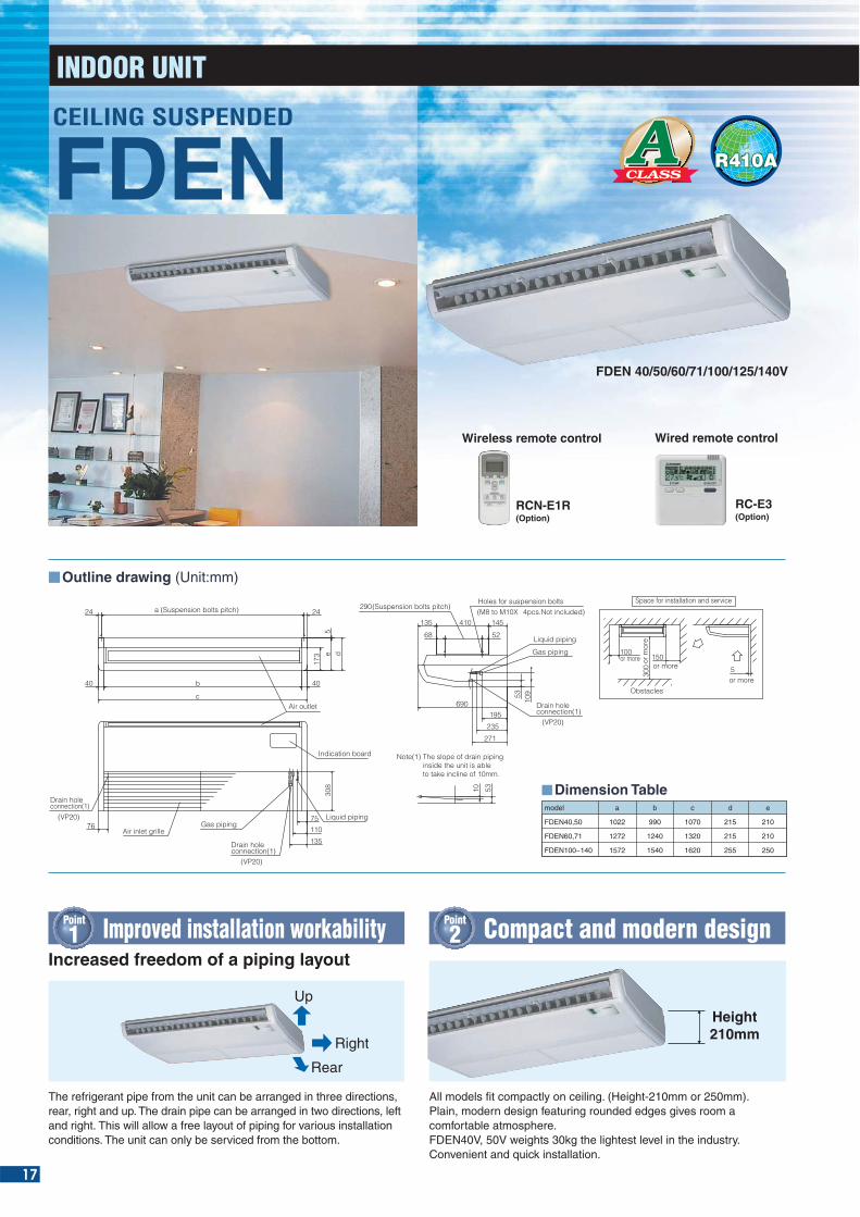
Outline drawing (Unit:mm)
model
FDEN40,50
FDEN60,71
FDEN100~140
a
1022
1272
1572
b
990
1240
1540
c
1070
1320
1620
d
215
215
255
e
210
210
250
Dimension Table
68
410
690
135 145
271
235
10953
195
52
290(Suspension bolts pitch)Holes for suspension bolts(M8 to M10X 4pcs.Not included)
Liquid piping
Gas piping
Drain holeconnection(1)
(VP20)
300
100150
5
Space for installation and service
or more
or moreor more or
mor
e
Obstacles
10 53
Note(1) The slope of drain piping inside the unit is able to take incline of 10mm.
Drain hole
7675
110
135
308
b
d
c
40
24
e5
173
40
24a (Suspension bolts pitch)
Air outlet
Liquid pipingGas piping
Indication board
Air inlet grille
connection(1)(VP20)
Drain holeconnection(1)
(VP20)
FDEN 40/50/60/71/100/125/140V
�����CLASSAAA
RCN-E1R(Option)
RC-E3(Option)
Wireless remote control Wired remote control
The refrigerant pipe from the unit can be arranged in three directions, rear, right and up. The drain pipe can be arranged in two directions, left and right. This will allow a free layout of piping for various installation conditions. The unit can only be serviced from the bottom.
Increased freedom of a piping layout
Point
1 Improved installation workability
All models fit compactly on ceiling. (Height-210mm or 250mm). Plain, modern design featuring rounded edges gives room a comfortable atmosphere.FDEN40V, 50V weights 30kg the lightest level in the industry. Convenient and quick installation.
Point
2
Rear
Right
UpHeight210mm
Compact and modern design
FDENCEILING SUSPENDED

18
Reviewing sirocco fan (diameter and wide) enables
drastic reduction of noise level.
35
40
45
20
25
30
50
1.5 2.0 2.5 3.0 4.0 5.0
38 39 38 39 38
43 44 43 43
6.0HP
3937 37
Former model
New model
Point
3 New design --- Drastic-reduction of noise level
Sound pressure level:dB(A)Lo-mode
dB(A)
AISO-T1(JIS)
ISO-T1(JIS)
Cooling/HeatingCooling/HeatingCooling/Heating
IndoorOutdoorIndoorOutdoorHeight x Width x Depth
Height x Width x Depth
Liquid/Gas
between O/Uand I/U
Cooling
Heating
kW
kW
kW
A
dB(A)
CMM
mmkg
mmkg
kg(m)ø
m<O/U>O/UI/UO/UI/UO/U
FDEN40ZHXVFDEN40V
SRC40ZHX-S
Hi:39 Me:38 Lo:3747
Hi:11 Me:9 Lo:7
210x1,070x69030
FDEN60ZHXVFDEN60V
SRC60ZHX-S
FDEN50ZHXVFDEN50V
SRC50ZHX-S
4.0(1.8~4.7)
4.5(2.0~5.4)
1.04/1.133.85/3.98
A/A
5.6(2.8~6.3)
6.7(3.1~7.1)
1.95/2.122.87/3.16
C/D
Hi:41 Me:39 Lo:3848
Hi:18 Me:14 Lo:12
210x1,320x69036
5.0(2.2~5.6)
5.4(2.5~6.3)
1.59/1.583.14/3.42
B/B5
40
RCN-E1R, RC-E3640x800(+71)x290
45ScrollEEV
1.4(15)6.35/12.7
302020
18~30-15~4318~30-15~24
SPECIFICATIONS
Indo
or u
nitO
utdo
or u
nit
Ran
ge o
fus
age
Lim
itatio
ns
1Phase 220-240V 50HZ , 1Phase 220V 60Hz
Inverter
ISO-T1(JIS)
ISO-T1(JIS)
Cooling/HeatingCooling/HeatingCooling/Heating
IndoorOutdoorIndoorOutdoorHeight x Width x Depth
Height x Width x Depth
Liquid/Gas
between O/Uand I/U
Cooling
Heating
kW
kW
kW
A
dB(A)
CMM
mmkg
mmkg
kg(m)ø
m<O/U>O/UI/UO/UI/UO/U
FDEN125VNVFDEN125VFDC125VN
FDEN140VNVFDEN140VFDC140VN
7.1(3.2~8.0)
8.0(3.6~9.0)
2.01/2.213.53/3.62
A/A
Hi:41 Me:39 Lo:3848
Hi:18 Me:14 Lo:12Cooling:60 Heating:50210x1,320x690
36
750x880(+88)x34060
2.95(30)9.52/15.88
-10~24
FDEN71VNVFDEN71VFDC71VN
SPECIFICATIONS
Indo
or u
nitO
utdo
or u
nit
Ran
ge o
fus
age
Lim
itatio
ns
1Phase 220-240V 50HZ , 1Phase 220V 60Hz
Inverter12.5
(5.0~14.0)14.0
(4.0~16.0)
4.10/3.653.05/3.84
B/A
Cooling:50 Heating:51
14.0(5.0~14.5)
16.0(4.0~16.5)
4.98/4.692.81/3.41
C/B5
51
RCN-E1R, RC-E3
RotaryEEV
503015
18~30-15~43*2
18~30-15~24
250x1,620x69046
845x970x37074
3.8(30)9.52/15.88
Hi:46 Me:44 Lo:43
Hi:29 Me:26 Lo:23Cooling:75 Heating:73
FDEN100VNVFDEN100VFDC100VN
10.0(4.0~11.2)
11.2(4.0~12.5)
2.85/2.973.51/3.77
A/A
Hi:44 Me:41 Lo:3949
Hi:26 Me:23 Lo:21Cooling:76 Heating:74
FDEN100VSVFDEN100VFDC100VS
FDEN125VSVFDEN125VFDC125VS
3phase,380-415V 50Hz/380V 60Hz
Hi:46 Me:44 Lo:43
Hi:29 Me:26 Lo:23Cooling:75 Heating:73
FDEN140VSVFDEN140VFDC140VS
10.0(4.0~11.2)
11.2(4.0~12.5)
2.85/2.973.51/3.77
A/A
Hi:44 Me:41 Lo:3949
Hi:26 Me:23 Lo:21Cooling:76 Heating:74
12.5(5.0~14.0)
14.0(4.0~16.0)
4.10/3.653.05/3.84
B/A
Cooling:50 Heating:51
14.0(5.0~14.5)
16.0(4.0~16.5)
4.98/4.692.81/3.41
C/B
51
The data are measured under the following conditions(ISO-T1).Cooling:Indoor temp. of 27˚CDB, 19˚CWB, and outdoor temp. of 35˚CDB.Heating:Indoor temp. of 20˚CDB, and outdoor temp. of 7˚CDB, 6˚CWB.
*1 : Indicates the value in an anechoic chamber. During operation these values are somewhat higher due to ambient conditions.
*2 : If a cooling operation is conducted when the outdoor air temperature is –5˚C or lower, the outdoor unit should be installed at a place where it is not influenced by natural wind. If wind blows, the low pressure will drop and compressor frequency will increase, this will cause the capacity to drop and may cause the unit to break down.
Set model nameIndoor nameOutdoor name
Power source
TypeNominal cooling capacity (Min~Max)Nominal heating capacity (Min~Max)InputCOPEnergy labelInrush current
Sound Ievel*1
Air flow
Exterior dimensionsNet weightRemote controlExterior dimensionsNet weightType of compressorRef.controlRef.amount prechargedRef.piping size Ref.piping length Vertical height difference
Air temp.

19
OUTDOOR UNIT (1.5-10.0HP)
Piping size (diameter) reduced
Installation workability
Height difference(Outdoor>indoor)
Piping length
3~10.0HP 30m
1.5 ~ 2.5HP : 30m3.0 ~ 6.0HP : 50m8.0 ~10.0HP : 70m
Enhanced installation workability thanks to the extended pipe length – longest levelin the industry, pre-charged refrigerant and reduced piping size.
Pipe length can be extended up to 70m. (8.0-10.0
HP) This opens up the possibility to apply to
large-scale commercial facilities as well, which
conventionally called for multiple type models.
Refrigerant pre-charged pipe length
extends up to 30m. (1.5~2.5HP:15m)
This eliminates the need to add
refrigerant on site, which sets it free
from trouble of excessive or
insufficient charging of refrigerant,
and allows carrying out the installation
smoothly.
Refrigerant piping size has been reduced in order to adapt to new high-density and
high-pressure refrigerant R410A.This has enabled to realize a higher refrigeration
capacity and reduced the pressure loss, which allows further reducing the piping
work cost.
Refrigerant may be recharged, of course, when it has leaked accidentally.
R407C R410A
15.88 12.728.58 22.22
1.5 2.0 2.5 3.0 4.0 5.0 6.0 8.0 10.0
Liquid
HP
Gas
Former model (R407C)
New model (R410A)
Former model (R407C)
New model (R410A)
6.35
-
12.7
-
6.35
6.35
12.7
15.88
6.35
9.52
12.7
15.88
9.52
9.52
15.88
15.88
9.52
9.52
15.88
19.05
9.52
9.52
15.88
19.05
9.52
-
15.88
-
9.52
12.7
22.22*
25.4
12.7
15.88
22.22*
28.58
*Use the reducer kit.
SRC40ZHX-SSRC50ZHX-SSRC60ZHX-S
(1.5HP~2.5HP)
FDC100VNFDC125VNFDC140VNFDC100VSFDC125VSFDC140VS
(4.0HP~6.0HP)
FDC200VS(8.0HP)
FDC250VS(10.0HP)
FDC71VN(3.0HP)
1.5 ~ 2.5HP 20m
Point
1 Pipe length – 70m Point
2 Refrigerant pre-charged pipe length extending to 30m
Point
3 Reduced refrigerant piping size that significantly enhances the installation workability
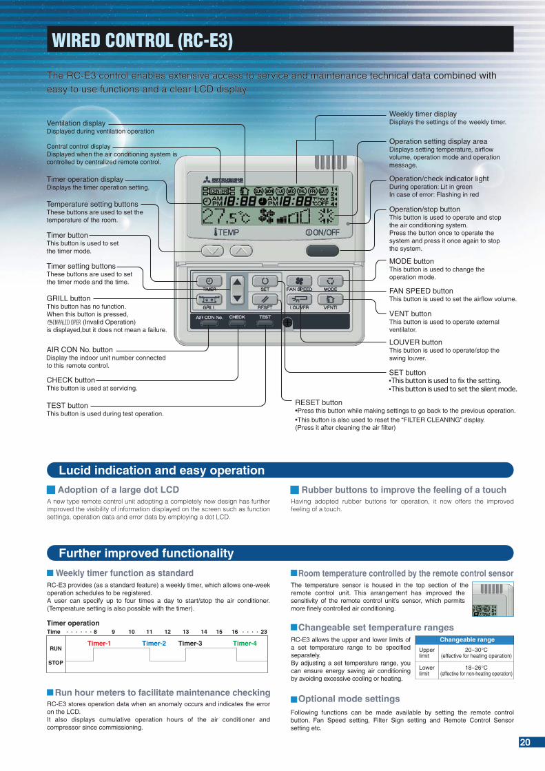
The RC-E3 control enables extensive access to service and maintenance technical data combined witheasy to use functions and a clear LCD display.
20
RC-E3 stores operation data when an anomaly occurs and indicates the error on the LCD.It also displays cumulative operation hours of the air conditioner and compressor since commissioning.
Run hour meters to facilitate maintenance checkingOptional mode settings
Weekly timer function as standardThe temperature sensor is housed in the top section of the remote control unit. This arrangement has improved the sensitivity of the remote control unit’s sensor, which permits more finely controlled air conditioning.
Room temperature controlled by the remote control sensorRC-E3 provides (as a standard feature) a weekly timer, which allows one-week operation schedules to be registered. A user can specify up to four times a day to start/stop the air conditioner. (Temperature setting is also possible with the timer).
Following functions can be made available by setting the remote control button. Fan Speed setting, Filter Sign setting and Remote Control Sensor setting etc.
Lucid indication and easy operation
Further improved functionality
A new type remote control unit adopting a completely new design has further improved the visibility of information displayed on the screen such as function settings, operation data and error data by employing a dot LCD.
Adoption of a large dot LCDHaving adopted rubber buttons for operation, it now offers the improved feeling of a touch.
Rubber buttons to improve the feeling of a touch
Changeable range
Upperlimit
Lowerlimit
20~30°C(effective for heating operation)
18~26°C(effective for non-heating operation)
RC-E3 allows the upper and lower limits of a set temperature range to be specified separately.By adjusting a set temperature range, you can ensure energy saving air conditioning by avoiding excessive cooling or heating.
Changeable set temperature ranges
WIRED CONTROL (RC-E3)
The RC-E3 control enables extensive access to service and maintenance technical data combined witheasy to use functions and a clear LCD display.The RC-E3 control enables extensive access to service and maintenance technical data combined witheasy to use functions and a clear LCD display.

21
SC-SL1N-E
SC-ADN-E
KX6 series
Up to 96 groups (64 indoor unit x 2 SUPERLINK-2 systems) are controlled from the Internet Explorer.
Up to 96 groups (64 indoor unit x 2 SUPERLINK-2 systems) are controlled centrally from a BMS.
*Additional engineering service cost etc. is required. Shipment will be available from July 2008.
Up to 96 indoor units (48 indoor unit x 2) are linked as an open network! Centrally controlled through LonWorks!
Start/stop control of up to 16 indoor units is possible either individually or collectively. With simple operations, you can effect centralized control.
Centralized control of up to 64 indoor units. It can allow connection with a weekly timer without using any interface.
Easy operation realized with a large color LCD and touch panel. Up to 128 indoor units can be controlled, when three SUPERLINK-2 systems are connected.
SC-SL1N-E
SC-WGWN-A/B*(SC-WGWN-B is with electric power calculation function)
PC windows central control
SC-BGWN-A*(BACnet gateway)
BMS interface unit
SC-LGWN-A*(LonWorks gateway)
SC-SL2N-ECentral Control
SC-SL3N-AE/BE
Control SystemControl System SUPERLINK-SUPERLINK-
SC-ADN-E
RAC series(SRK50/60ZHX-S)
SC-ADN-E
SC-BIKN-E
SC-SL2N-E

22
Outdoor unit
Internal/external Crossing
Indoor unit
Remote controlSL E Board
Networkoptions
X Y
X Y X Y A B
A B
Outdoor unit
Internal/external Crossing
Inside Inside Inside Inside
R RSL EBoard
Networkoptions
Outdoor unit
Internal/external Crossing
Inside Inside Inside Inside
R RSL EBoard
Outdoor unit
Internal/external Crossing
Inside Inside Inside
R RSL EBoard
Networkoptions
Outdoor unit
Internal/external Crossing
Inside Inside
SL EBoard
Networkoptions
Outdoor unit
Internal/external Crossing
Inside Inside
SL EBoard
Networkoptions
Wireless Kit
Wireless remote control
Basic Connections Plural Controls by Multiple Remote Controls. Mixture of Multiple Units
Plural Controls by Multiple Remote Controls. Mixture of Multiple Units Without Remote Control Wireless Kit
(3) Metal box dimension
85
40
35
30
905
100
70
22.5
2-ø6
SUPERLINK E BOARD (SC-ADN-E)This board is used when conducting control of the single package (wired remote control unit) 1-type series using a network option (SC-SL1N-E, SC-SL2N-E, etc).
(1) Functions (a) Transmits the settings from the network option to the indoor units. (b) Returns the priority indoor unit data in response to a data request from the network option. (c) Inspects the error status of connected indoor units and transmits the inspection codes to the network option. (d) A maximum of 16 units can be controlled (if in the same operation mode).
(2) Wiring connection diagram
Set up “000” to “127” using address switch on the SL E board.
• Transmit the information of plural “Master” units to the network.
• Transmit the abnormalities of the “Slave” units to the network.
Setting the plural “Master/Slave” units with the dip SW of the printed circuit board.
Setting the “Master/Slave” remote controls with the dip SW of the remote control board.
Set the SL E board dip SW to “Master” SW3-1 ON.The network option SLA-1-E, SL1N-E is not allowed (This will disturb switching of the operation mode)
Control System SUPERLINK-
Connected to the remote controller terminals (no polarity) (the length should be 600 m or shorter)
Connected to the terminals forSuperlink signal linesMVVS 0.75 - 1.25mm2
SL E board
OFF SW3 SW1
LED
2
Run
Abnorm
al LED
3
SW2
ON
A
B
X
Y
X
Y
A
B
Blue
Blue
Black
White
Master/Sub address
Network address setting switches [000]-(127)
200 m or shorter300 m or shorter400 m or shorter600 m or shorter
0.5 mm2 x 2 cores0.75 mm2 x 2 cores1.25 mm2 x 2 cores2.0 mm2 x 2 cores

23
FDC71VN (unit:mm)
SRC40ZHX-S, 50ZHX-S, 60ZHX-S (unit:mm)
MarkABDE
ItemRefrigerant gas side pipe connection tapRefrigerant liquid side pipe connection tapDrain discharge portAnchor bolt hole
ø12.7(flare)ø6.35(flare)
ø20.5x5places M10x4places
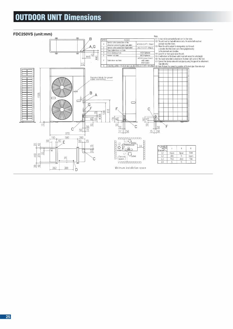
OUTDOOR UNIT Dimensions
Notes:(1) It must not be surrounded by walls on the four sides.(2) The unit must be fixed with anchor bolts.An anchor bolt must not protrude more than
15mm.(3) Where the unit is subject to strong winds, lay it in such a direction that the blower outlet
faces perpendicularly to the dominant wind direction.(4) Leave a 1m or larger space above the unit.(5) A wall in front of the blower outlet must not exceed the units height.(6) The unit name plate is attached on the lower right corner of the front panel.
280Open
80250
2807580
Open
Open100100250
321
L1
L2
L3
L4
Dimensions
Examples of installation
Mark
A
B
CDEF
ItemRefrigerant gas side pipeconnection tapRefrigerant liquid side pipeconnection tapPipe/cable draw-out portDrain discharge portAnchor bolt holeCable draw-out port
ø15.88(flare)
ø9.52(flare)
ø20.3x3places M10x4placesø30.3x3places
Notes:(1) It must not be surrounded by walls on the four sides.(2) The unit must be fixed with anchor bolts.An anchor
bolt must not protrude more than 15mm.(3) Where the unit is subject to strong winds, lay it in such
a direction that the blower outlet faces perpendicularly to the dominant wind direction.
(4) Leave a 1m or larger space above the unit.(5) A wall in front of the blower outlet must not exceed the
units height.(6) The unit name plate is attached on the lower right
corner of the front panel.
500Open100250
Open250150250
Open300100250
321
L1
L2
L3
L4
Dimensions
Examples of installation
222
40
20
40
20
340
380
310
47
40
55
580
150
150
30
30
48.5
103.
3
750
24.1
D
2-ø15 25.829.8
87.9880150580150
61
53222360
15
340
6147
.5
1938
019
418
165.5 25.5
Terminal block
E
D
B
A
Minimum installation space
Intake
outlet
Intake
Servicespace
L1
L2L3
L4
327.3
43.5
290
83.5
24.3
312.
514
.8
351.
6
327.3
89 510
800
201
17.9
71.2E
D 50.6
12
640
12.4
9342
.5
148.4 33.5
40°
40°
Check joint
Terminal block
B
A
L2 L3
outlet L1
L4
Intake
Servicespace
Intake
24
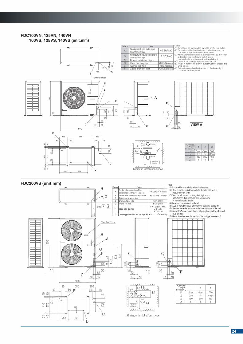
FDC200VS (unit:mm)
Minimum installation space
Intake
outlet
Intake
Servicespace
L1
L2L3
L4
FDC100VN, 125VN, 140VN100VS, 125VS, 140VS (unit:mm)
Mark
A
B
CDEF
ItemRefrigerant gas side pipeconnection tapRefrigerant liquid side pipeconnection tapPipe/cable draw-out portDrain discharge portAnchor bolt holeCable draw-out port
ø15.88(flare)
ø9.52(flare)
ø20.3x3places M10x4placesø30.3x3places
Notes:(1) It must not be surrounded by walls on the four sides.(2) The unit must be fixed with anchor bolts.An anchor
bolt must not protrude more than 15mm.(3) Where the unit is subject to strong winds, lay it in such
a direction that the blower outlet faces perpendicularly to the dominant wind direction.
(4) Leave a 1m or larger space above the unit.(5) A wall in front of the blower outlet must not exceed the
units height.(6) The unit name plate is attached on the lower right
corner of the front panel.
500Open1505
Open5
3005
Open3001505
321
L1
L2
L3
L4
Dimensions
Examples of installation
A
51
40 36
100
845
10
110
50
195 242
279
970
50 15
55
5027
52
110
50
195
B
B
A
A
Terminal block
F
CC VIEW AC 5015
7050
150
40
F
E
370
4040
410
2020
55
60
388262
38
60
190 580 200
60 15
103
15
C
D
25
OUTDOOR UNIT Dimensions
FDC250VS (unit:mm)
A debut of the enzyme sterilizing filter to which enzymes used in detergent, etc. are chemically bonded.

26
Applicable indoor unit models Ceiling cassette -4way- FDT, Ceiling suspended FDE
Enzymes used for filters are natural lytic enzymes.The lytic enzymes attack cell walls of microorganisms trapped on a filter and destroy them, so that they will show a powerful sterilizing effect to decrease the number of molds and bacteria. Where such enzymes exist, air filters are kept sanitary and clean. Naturally, air passing through such filters is clean and safe.
A debut of the enzyme sterilizing filter to which enzymes used in detergent, etc. are chemically bonded.A debut of the enzyme sterilizing filter to which enzymes used in detergent, etc. are chemically bonded.
Enzyme filter Conventional filter
A filter coated with bacterium has been placed on the gelatin cultivate medium for seven days
No breeding on the filter
Filter
Breeding on and around the filter
Filter
Mold
Enzyme Sterilizing Filter
Effect on bacterium Effect on molds
Enzyme's sterilizing mechanism
Conventional Filter
Air
flo
w
Enzyme Filter
Air
flo
w
Optional Parts
CouplingCell wallFilter fiber
EnzymeBacterium
EnzymeEnzyme
Powerful sterilizing effect
Sterilization
Enzymeloaded fiber
Live bacterium
Destroyingbacteria
May 2008R
Safety Precautions
Before starting use
Printed in Japan
Air-conditioner usage targetThe air-conditioner described in this catalog is a dedicated cooling/heating device for human use. Do not use it for special applications such as the storage of foodstuffs, animals or plants, precision devices or valuable art, etc. This could cause the quality of the items to drop, etc. Do not use this for cooling vehicles or ships. Water leakage or current leaks could occur.
Before useAlways read the "User,s Manual" thoroughly before starting use.
InstallationAlways commission the installation to a dealer or specialist. Improper installation will lead to water leakage, electric shocks and fires. Use the MHI-designated products for the accessories such as the air purifier, humidifier, and auxiliary electric heater for heating.
Usage placeDo not install in places where combustible gas could leak or where there are sparks. Installation in a place where combustible gas could be generated, flow or accumulate, or places containing carbon fibers could lead to fires.
Refrigerant leakageThe refrigerant gas (R410A) used for Air conditioner is non-toxic and inflammable in its original state. However, in consideration of a state where the refrigerant leaks into the room, measures against refrigerant leaks must be taken in small rooms where the tolerable level could be exceeded. Take measures by installing ventilation devices, etc.
Use in snowy areasTake the following measures when installing the outdoor unit in snowy areas.
·Snow showInstall a snow-prevention hood so that the snow does not obstruct the air intake port, and so that the snow does not enter and freeze in the outdoor unit.
·Snow pilingIn areas with heavy snow fall, the piled snow could block the air intake port. In this case, a frame that is 50cm or higher than the estimated snow fall must be installed underneath the outdoor unit.
Automatic defrosting deviceIf the temperature is low, and the humidity is high, frost will stick to the heat exchanger of the outdoor unit. If use is continued, the heating performance will drop. The "Automatic defrosting device" will function to remove this frost. After heating for approx, three to ten minutes, it will stop, and the frost will be removed. After defrosting, hot air will be blown again.
Servicing the air-conditionerAfter the air-conditioner is used for several seasons, dirt will build up in the air-conditioner causing the performance to drop. In addition to regular servicing, we recommend the maintenance contract (charged for) by a specialist.
Heating performanceThe heating performance values (kW) described in catalog are the values obtained by operating at an outdoor temperature of 7 C and indoor temperature of 20 C as set forth in the ISO Standards. As the heating performance decreases as the outdoor temperature drops, if the outdoor temperature is too low and the heating performance is insufficient, use other heating appliances as well.
Indication of sound valuesThe sound values are the values (A scale) measured in a chamber such as an anechoic chamber following the ISO Standards. In the actual installation state, the value is normally larger than the values given in the catalog due to the effect of surrounding noise and echo. Take this into consideration when installing.
Use in oil atmosphereAvoid installing this unit in as atmosphere where oil scatters or builds up, such as in a kitchen or machine factory. If the oil adheres to the heat exchanger, the heat exchanging performance will drop, mist may be generated, and the synthetic resin parts may deform and break.
Use in acidic or alkaline atmosphereIf this unit is used in an acidic or alkaline atmosphere such as hot spring areas having high levels of sulfuric gases, places where the exhaust of the heat exchanger is sucked in, or at coastal areas where the unit is subject to salt breezes, the outer plate or heat exchanger, etc., will corrode.
Use in places with high ceilingsIf the ceiling is high, install a circulator to improve the heat and air flow distribution when heating.
HB91-08P01E-B-0
Because of our policy of continuous improvement, we reserve right to make changes in all specifications without notice.
Head Office : Mitsubishi Heavy Industries, Ltd. 16-5 2-Chome Kounan Minato-ku Tokyo 108-8215, Japan
Our factories are ISO9001 and ISO14001 certified.
BIWAJIMA PLANT Mitsubishi Heavy Industries, Ltd.
Air-conditioning & Refrigeration Systems HeadquartersCertificate number : JQA-0709
Date of certification : December 1994
BIWAJIMA PLANT Mitsubishi Heavy Industries, Ltd.
Air-conditioning & Refrigeration Systems HeadquartersCertificate number : JQA-EM0256
Date of certification : November 1998
MITSUBISHI HEAVY INDUSTRIES-MAHAJAK AIR CONDITIONERS CO., LTD.
Certificate Number : 04100 1998 0813Date of Registration : October 1998
Mitsubishi HeavyIndustries-Haier (Quingdao)
Air-conditioners Co.,Ltd.Certificate number : 01-1998-083
Date of certification : December 1998
MITSUBISHI HEAVY INDUSTRIES-MAHAJAK AIR CONDITIONERS CO.,LTD.
Certificate Number : 04104 1998 0813 E5Date of Registration : December 2005
��� �����
Certificate 04104 1998 0813 E5
Mitsubishi HeavyIndustries-Haier (Quingdao)
Air-conditioners Co.,Ltd.Certificate Number : 5170-1996-AQ-RCG-RvA
Date of certification : April 1996
Certified ISO 9001 Certified ISO 14001


![Ansvarlig søker hw 08 09 16.ppt [Kompatibilitetsmodus]byggebolig.no/imageoriginals/d2653822b38f82f6300ef7aec57... · 2014. 10. 9. · Ansvar etter pbl § 93b – Alle deler av tiltaket](https://img.pdfslide.net/doc/110x75/60d612cf1bfb9c237007b29b/ansvarlig-sker-hw-08-09-16ppt-kompatibilitetsmodus-2014-10-9-ansvar-etter.jpg)