Embed Size (px)
Citation preview
Si04 - 306E
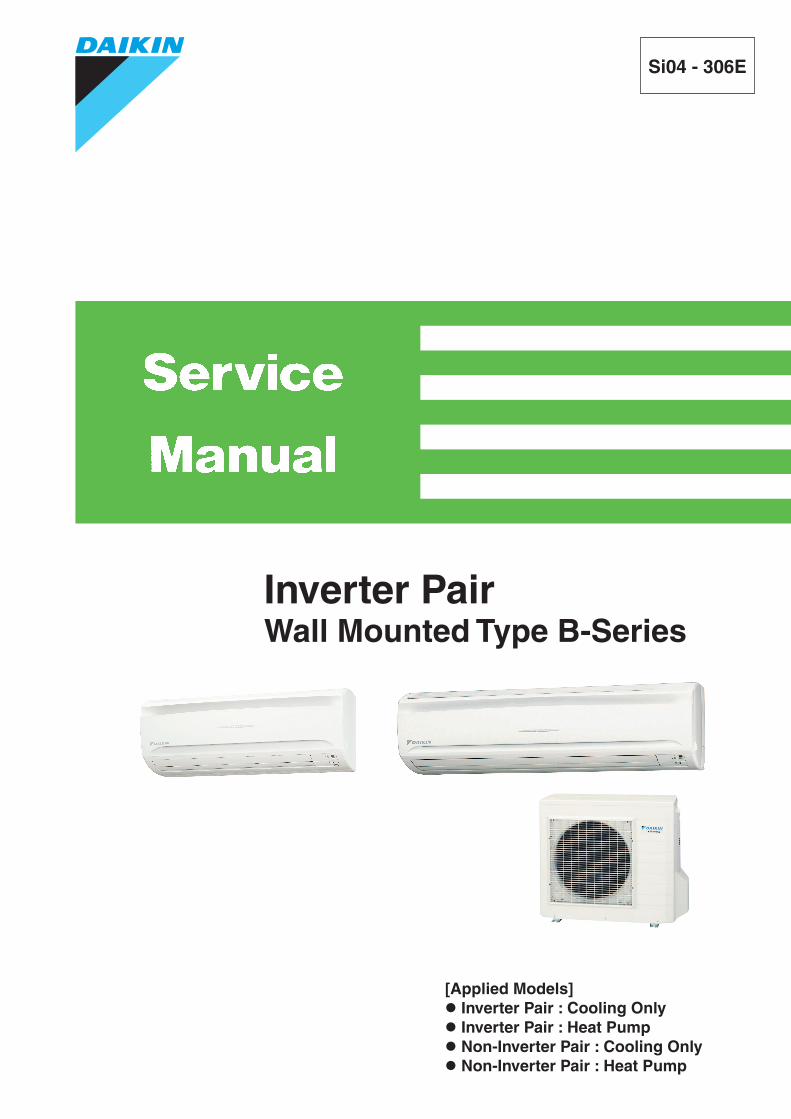
[Applied Models] Inverter Pair : Cooling Only Inverter Pair : Heat Pump Non-Inverter Pair : Cooling Only Non-Inverter Pair : Heat Pump
Inverter PairWall Mounted Type B-Series
Si04-306E
Inverter PairB-Series
Cooling OnlyIndoor Unit<R410A>FTKS50BVMA(8) FTKS50BVMB FTS50BVMBFTKS60BVMA FTKS60BVMB FTS60BVMBFTKS71BVMA FTKS71BVMB FTKS71BAVMB<R22>FTKD50BVM FTKD50BVMA FTKD50BVMT FTKD18BVMSFTKD60BVM FTKD60BVMA FTKD60BVMT FTKD24BVMSFTKD71BVM FTKD71BVMA FTKD71BVMT FTKD28BVMS
Outdoor Unit<R410A>RKS50BVMA RKS50BVMB(9) RKS50B2VMB RS50BVMBRKS50BVMG RKS60BVMB(9) RKS60B2VMB RS60BVMBRKS60BVMA RKS71BVMB(9) RKS71B2VMB RS50B2VMBRKS71BVMA RKS71B3VMB RS60B2VMB
<R22>RKD50BVM RKD50BVMA RKD50BVMT RKD18BVMSRKD60BVM RKD60BVMA RKD60BVMT RKD24BVMSRKD71BVM RKD71BVMA RKD71BVMT RKD28BVMS
Heat PumpIndoor Unit<R410A>FTXS50BVMA FTXS50BVMB ATXS50CVMB FTYS50BVMBFTXS60BVMA FTXS60BVMB ATXS50DVMB FTYS60BVMBFTXS71BVMA FTXS71BVMB FTXS71BAVMB<R22>FTXD50BVMA FTXD50BVMT FTXD50BV4FTXD60BVMA FTXD60BVMT FTXD80CV4FTXD71BVMA FTXD71BVMT
Outdoor Unit<R410A>RXS50BVMA RXS50BVMB ARXS50CVMB RYS50BVMBRXS60BVMA RXS60BVMB ARXS50C2VMB RYS60BVMBRXS71BVMA RXS71BVMB RXS50B2VMB RYS50B2VMB
RXS60B2VMB RYS60B2VMBRXS71B2VMBRXS71B3VMB
<R22>RXD50BVMA RXD50BVMT RXD50BV4RXD60BVMA RXD60BVMT RXD80CV4RXD71BVMA RXD71BVMT
Table of Contents i
Si04-306E
1. Introduction .............................................................................................v1.1 Safety Cautions ........................................................................................v1.2 Used Icons .............................................................................................. ix
Part 1 List of Functions ................................................................11. List of Functions ......................................................................................2
1.1 R-410A Series ..........................................................................................21.2 R-22 Series ..............................................................................................8
Part 2 Specifications ..................................................................131. Specifications ........................................................................................14
1.1 Cooling Only - R-410A Series ................................................................141.2 Cooling Only - R-22 Series.....................................................................191.3 Heat Pump - R-410A Series...................................................................231.4 Heat Pump - R-22 Series .......................................................................30
Part 3 Printed Circuit Board Connector Wiring Diagram ...........371. Printed Circuit Board Connector Wiring Diagram..................................38
1.1 Indoor Unit..............................................................................................381.2 Outdoor Unit ...........................................................................................40
Part 4 Function and Control........................................................431. Main Functions......................................................................................44
1.1 Frequency Principle................................................................................441.2 Power-Airflow Dual Flaps, Wide Angle Louvers and Auto-Swing ..........461.3 Fan Speed Control for Indoor Units........................................................471.4 Programme Dry Function .......................................................................481.5 Automatic Operation...............................................................................491.6 Thermostat Control.................................................................................501.7 Night Set Mode.......................................................................................511.8 INTELLIGENT EYE................................................................................521.9 HOME LEAVE Operation .......................................................................541.10 Inverter POWERFUL Operation .............................................................551.11 Other Functions......................................................................................56
2. Function of Main Structural Parts..........................................................582.1 Function of Thermistor ...........................................................................58
3. Control Specification .............................................................................603.1 Mode Hierarchy ......................................................................................603.2 Frequency Control..................................................................................613.3 Controls at Mode Changing / Start-up....................................................633.4 Discharge Pipe Temperature Control.....................................................643.5 Input Current Control..............................................................................643.6 Freeze-up Protection Control .................................................................653.7 Heating Peak-cut Control .......................................................................653.8 Fan Control.............................................................................................663.9 Liquid Compression Protection Function 2.............................................663.10 Low Hz High Pressure Limit ...................................................................673.11 Defrost Control .......................................................................................673.12 Electronic Expansion Valve Control .......................................................68
ii Table of Contents
Si04-306E
3.13 Malfunctions ...........................................................................................713.14 Forced Operation Mode .........................................................................733.15 Additional Function.................................................................................733.16 Facility Setting Switch (cooling at low outdoor temperature)..................74
Part 5 Operation Manual .............................................................751. System Configuration............................................................................762. Instruction..............................................................................................77
2.1 Safety Precautions .................................................................................772.2 Names of Parts.......................................................................................792.3 Preparation Before Operation ................................................................822.4 AUTO · DRY · COOL · HEAT · FAN Operation ......................................852.5 Adjusting the Airflow Direction................................................................872.6 POWERFUL Operation ..........................................................................892.7 OUTDOOR UNIT QUIET Operation.......................................................902.8 HOME LEAVE Operation .......................................................................912.9 INTELLIGENT EYE Operation ...............................................................932.10 TIMER Operation ...................................................................................952.11 Care and Cleaning .................................................................................972.12 Troubleshooting....................................................................................100
Part 6 Service Diagnosis...........................................................1031. Caution for Diagnosis..........................................................................1042. Problem Symptoms and Measures .....................................................1053. Service Check Function ......................................................................1064. Troubleshooting ..................................................................................109
4.1 Error Codes and Description ................................................................1094.2 Indoor Unit PCB Abnormality ...............................................................1104.3 Freeze-up Protection Control or High Pressure Control.......................1114.4 Fan Motor (DC Motor) or Related Abnormality.....................................1134.5 Thermistor or Related Abnormality (Indoor Unit)..................................1154.6 Signal Transmission Error (between Indoor and Outdoor Units)..........1164.7 OL Activation (Compressor Overload) .................................................1184.8 Compressor Lock .................................................................................1194.9 DC Fan Lock ........................................................................................1204.10 Input Over Current Detection ...............................................................1214.11 Four Way Valve Abnormality................................................................1234.12 Discharge Pipe Temperature Control...................................................1254.13 High Pressure Control in Cooling .........................................................1264.14 Position Sensor Abnormality ................................................................1284.15 CT or Related Abnormality ...................................................................1294.16 Thermistor or Related Abnormality (Outdoor Unit)...............................1314.17 Electrical Box Temperature Rise..........................................................1334.18 Radiation Fin Temperature Rise ..........................................................1354.19 Output Over Current Detection.............................................................1374.20 Insufficient Gas.....................................................................................1394.21 Low-voltage Detection..........................................................................141
5. Check ..................................................................................................1425.1 How to Check .......................................................................................142
Table of Contents iii
Si04-306E
Part 7 Removal Procedure ........................................................1511. Indoor Unit...........................................................................................152
1.1 Removal of the Air Filter / Front Panel .................................................1521.2 Removal of the Front Grille ..................................................................1551.3 Removal of the Horizontal Blades / Vertical Blades .............................1571.4 Removal of the Electrical Box / PCB / Swing Motor .............................1591.5 Removal of the Heat Exchanger ..........................................................1651.6 Removal of the Fan Rotor / Fan Motor.................................................168
2. Outdoor Unit........................................................................................1702.1 Removal of the Panels and Plates .......................................................1702.2 Removal of the Fan Motor / Propeller Fan ...........................................1742.3 Removal of the PCB / Electrical Box ....................................................1782.4 Removal of the Reactor........................................................................1862.5 Removal of the Sound Blanket.............................................................1882.6 Removal of the Four Way Valve...........................................................1902.7 Removal of the Electronic Expansion Valve.........................................1912.8 Removal of the Compressor.................................................................192
Part 8 Others .............................................................................1951. Others .................................................................................................196
1.1 Test Run from the Remote Controller ..................................................1961.2 Jumper Settings ...................................................................................1971.3 Application of Silicon Grease to a Power Transistor and
a Diode Bridge......................................................................................198
Part 9 Appendix.........................................................................1991. Piping Diagrams..................................................................................200
1.1 Indoor Units ..........................................................................................2001.2 Outdoor Units .......................................................................................201
2. Wiring Diagrams..................................................................................2072.1 Indoor Units ..........................................................................................2072.2 Outdoor Units .......................................................................................210
Index ............................................................................................. i
Drawings & Flow Charts ................................................................ v
iv Table of Contents
Si04-306E Introduction
1. Introduction1.1 Safety Cautions
Cautions and Warnings
Be sure to read the following safety cautions before conducting repair work.The caution items are classified into “ Warning” and “ Caution”. The “ Warning” items are especially important since they can lead to death or serious injury if they are not followed closely. The “ Caution” items can also lead to serious accidents under some conditions if they are not followed. Therefore, be sure to observe all the safety caution items described below.About the pictograms
This symbol indicates the item for which caution must be exercised. The pictogram shows the item to which attention must be paid.
This symbol indicates the prohibited action. The prohibited item or action is shown in the illustration or near the symbol.
This symbol indicates the action that must be taken, or the instruction. The instruction is shown in the illustration or near the symbol.
After the repair work is complete, be sure to conduct a test operation to ensure that the equipment operates normally, and explain the cautions for operating the product to the customer.
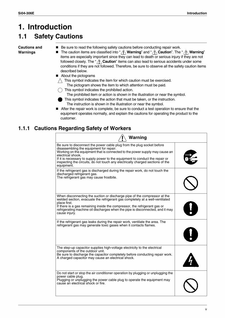
1.1.1 Cautions Regarding Safety of Workers
Warning
Be sure to disconnect the power cable plug from the plug socket before disassembling the equipment for repair.Working on the equipment that is connected to the power supply may cause an electrical shook.If it is necessary to supply power to the equipment to conduct the repair or inspecting the circuits, do not touch any electrically charged sections of the equipment.
If the refrigerant gas is discharged during the repair work, do not touch the discharged refrigerant gas.The refrigerant gas may cause frostbite.
When disconnecting the suction or discharge pipe of the compressor at the welded section, evacuate the refrigerant gas completely at a well-ventilated place first.If there is a gas remaining inside the compressor, the refrigerant gas or refrigerating machine oil discharges when the pipe is disconnected, and it may cause injury.
If the refrigerant gas leaks during the repair work, ventilate the area. The refrigerant gas may generate toxic gases when it contacts flames.
The step-up capacitor supplies high-voltage electricity to the electrical components of the outdoor unit.Be sure to discharge the capacitor completely before conducting repair work.A charged capacitor may cause an electrical shock.
Do not start or stop the air conditioner operation by plugging or unplugging the power cable plug.Plugging or unplugging the power cable plug to operate the equipment may cause an electrical shock or fire.
v
Introduction Si04-306E
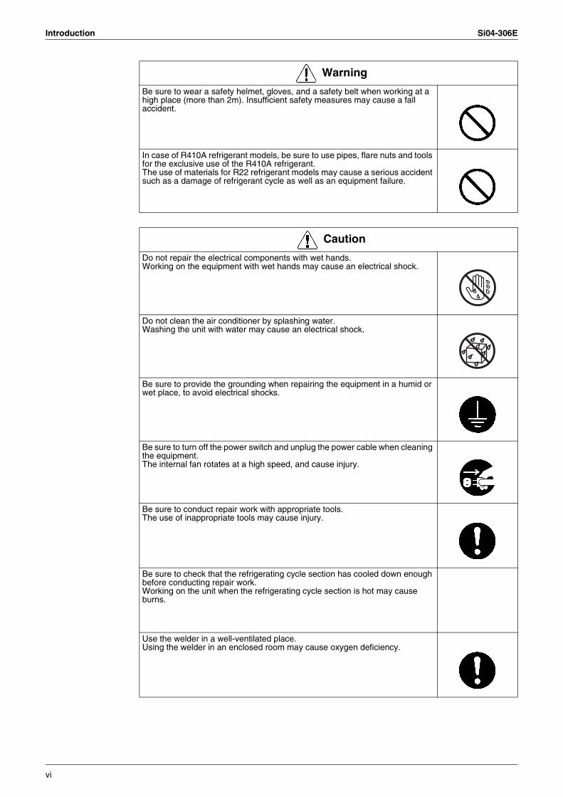
Be sure to wear a safety helmet, gloves, and a safety belt when working at a high place (more than 2m). Insufficient safety measures may cause a fall accident.
In case of R410A refrigerant models, be sure to use pipes, flare nuts and tools for the exclusive use of the R410A refrigerant.The use of materials for R22 refrigerant models may cause a serious accident such as a damage of refrigerant cycle as well as an equipment failure.
Warning
Caution
Do not repair the electrical components with wet hands.Working on the equipment with wet hands may cause an electrical shock.
Do not clean the air conditioner by splashing water.Washing the unit with water may cause an electrical shock.
Be sure to provide the grounding when repairing the equipment in a humid or wet place, to avoid electrical shocks.
Be sure to turn off the power switch and unplug the power cable when cleaning the equipment.The internal fan rotates at a high speed, and cause injury.
Be sure to conduct repair work with appropriate tools.The use of inappropriate tools may cause injury.
Be sure to check that the refrigerating cycle section has cooled down enough before conducting repair work.Working on the unit when the refrigerating cycle section is hot may cause burns.
Use the welder in a well-ventilated place.Using the welder in an enclosed room may cause oxygen deficiency.
vi
Si04-306E Introduction
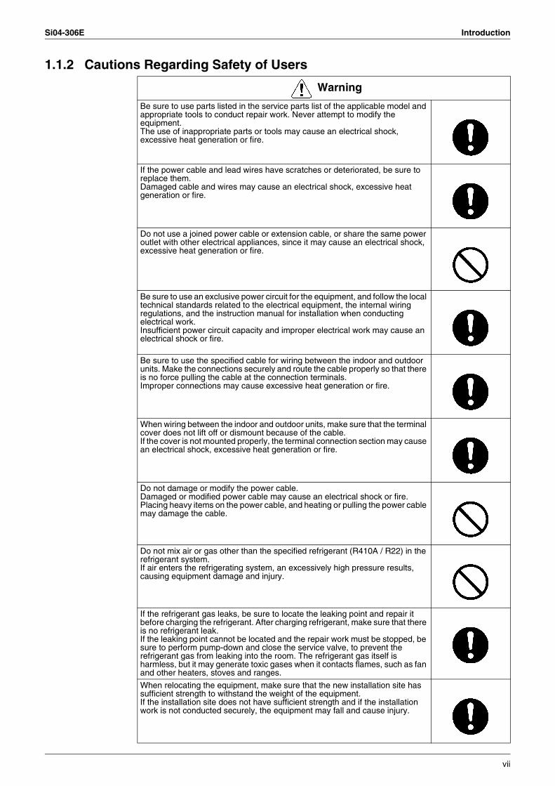
1.1.2 Cautions Regarding Safety of Users
Warning
Be sure to use parts listed in the service parts list of the applicable model and appropriate tools to conduct repair work. Never attempt to modify the equipment.The use of inappropriate parts or tools may cause an electrical shock, excessive heat generation or fire.
If the power cable and lead wires have scratches or deteriorated, be sure to replace them.Damaged cable and wires may cause an electrical shock, excessive heat generation or fire.
Do not use a joined power cable or extension cable, or share the same power outlet with other electrical appliances, since it may cause an electrical shock, excessive heat generation or fire.
Be sure to use an exclusive power circuit for the equipment, and follow the local technical standards related to the electrical equipment, the internal wiring regulations, and the instruction manual for installation when conducting electrical work.Insufficient power circuit capacity and improper electrical work may cause an electrical shock or fire.
Be sure to use the specified cable for wiring between the indoor and outdoor units. Make the connections securely and route the cable properly so that there is no force pulling the cable at the connection terminals.Improper connections may cause excessive heat generation or fire.
When wiring between the indoor and outdoor units, make sure that the terminal cover does not lift off or dismount because of the cable.If the cover is not mounted properly, the terminal connection section may cause an electrical shock, excessive heat generation or fire.
Do not damage or modify the power cable.Damaged or modified power cable may cause an electrical shock or fire.Placing heavy items on the power cable, and heating or pulling the power cable may damage the cable.
Do not mix air or gas other than the specified refrigerant (R410A / R22) in the refrigerant system.If air enters the refrigerating system, an excessively high pressure results, causing equipment damage and injury.
If the refrigerant gas leaks, be sure to locate the leaking point and repair it before charging the refrigerant. After charging refrigerant, make sure that there is no refrigerant leak.If the leaking point cannot be located and the repair work must be stopped, be sure to perform pump-down and close the service valve, to prevent the refrigerant gas from leaking into the room. The refrigerant gas itself is harmless, but it may generate toxic gases when it contacts flames, such as fan and other heaters, stoves and ranges.
When relocating the equipment, make sure that the new installation site has sufficient strength to withstand the weight of the equipment.If the installation site does not have sufficient strength and if the installation work is not conducted securely, the equipment may fall and cause injury.
vii
Introduction Si04-306E
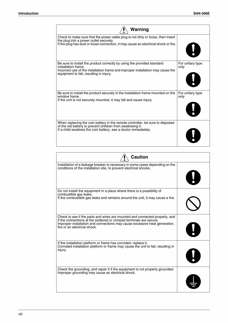
Check to make sure that the power cable plug is not dirty or loose, then insert the plug into a power outlet securely.If the plug has dust or loose connection, it may cause an electrical shock or fire.
Be sure to install the product correctly by using the provided standard installation frame.Incorrect use of the installation frame and improper installation may cause the equipment to fall, resulting in injury.
For unitary type only
Be sure to install the product securely in the installation frame mounted on the window frame.If the unit is not securely mounted, it may fall and cause injury.
For unitary type only
When replacing the coin battery in the remote controller, be sure to disposed of the old battery to prevent children from swallowing it.If a child swallows the coin battery, see a doctor immediately.
Warning
Caution
Installation of a leakage breaker is necessary in some cases depending on the conditions of the installation site, to prevent electrical shocks.
Do not install the equipment in a place where there is a possibility of combustible gas leaks.If the combustible gas leaks and remains around the unit, it may cause a fire.
Check to see if the parts and wires are mounted and connected properly, and if the connections at the soldered or crimped terminals are secure.Improper installation and connections may cause excessive heat generation, fire or an electrical shock.
If the installation platform or frame has corroded, replace it.Corroded installation platform or frame may cause the unit to fall, resulting in injury.
Check the grounding, and repair it if the equipment is not properly grounded.Improper grounding may cause an electrical shock.
viii
Si04-306E Introduction
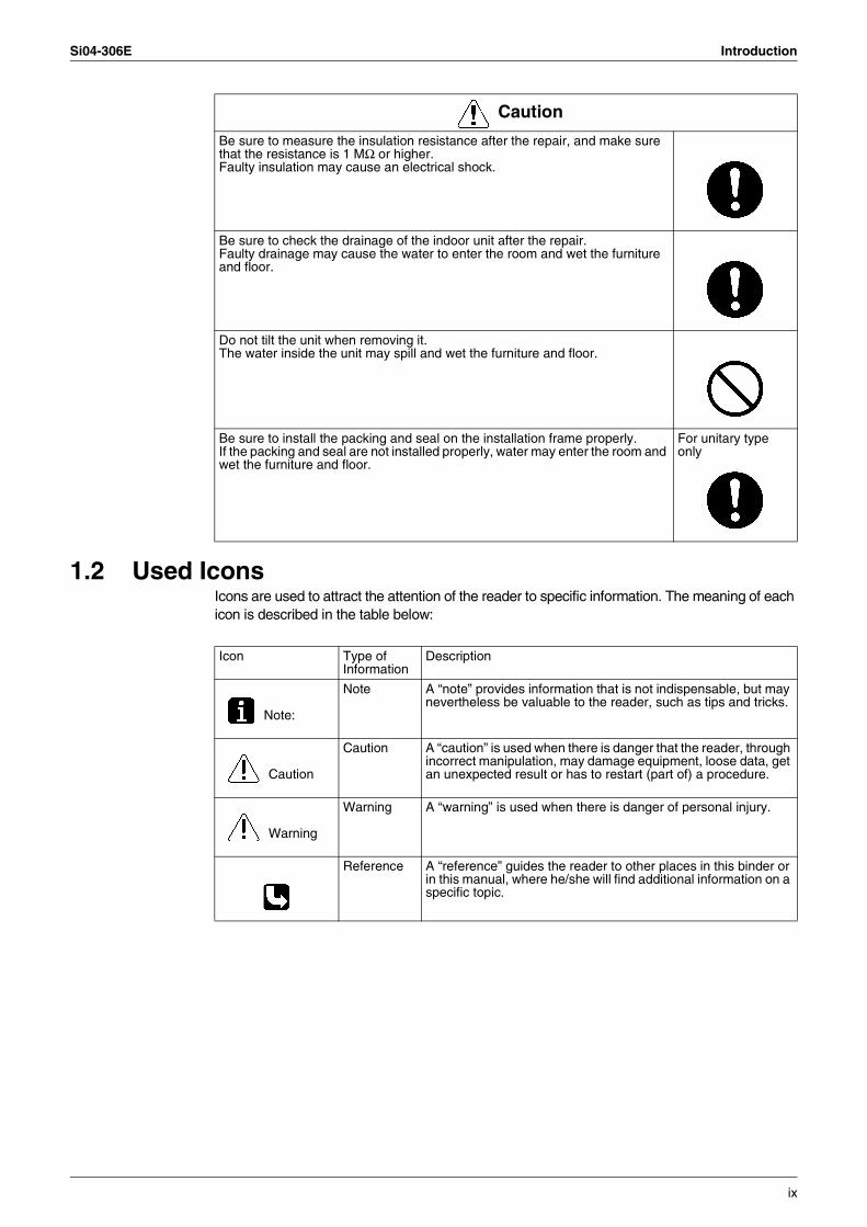
1.2 Used IconsIcons are used to attract the attention of the reader to specific information. The meaning of each icon is described in the table below:
Be sure to measure the insulation resistance after the repair, and make sure that the resistance is 1 MΩ or higher.Faulty insulation may cause an electrical shock.
Be sure to check the drainage of the indoor unit after the repair.Faulty drainage may cause the water to enter the room and wet the furniture and floor.
Do not tilt the unit when removing it.The water inside the unit may spill and wet the furniture and floor.
Be sure to install the packing and seal on the installation frame properly.If the packing and seal are not installed properly, water may enter the room and wet the furniture and floor.
For unitary type only
Caution
Icon Type of Information
Description
Note:
Note A “note” provides information that is not indispensable, but may nevertheless be valuable to the reader, such as tips and tricks.
Caution
Caution A “caution” is used when there is danger that the reader, through incorrect manipulation, may damage equipment, loose data, get an unexpected result or has to restart (part of) a procedure.
Warning
Warning A “warning” is used when there is danger of personal injury.
Reference A “reference” guides the reader to other places in this binder or in this manual, where he/she will find additional information on a specific topic.
ix
Introduction Si04-306E
x
Si04-306E
List of Functions 1
Part 1List of Functions
1. List of Functions ......................................................................................21.1 R-410A Series ..........................................................................................21.2 R-22 Series ..............................................................................................8
List of Functions Si04-306E
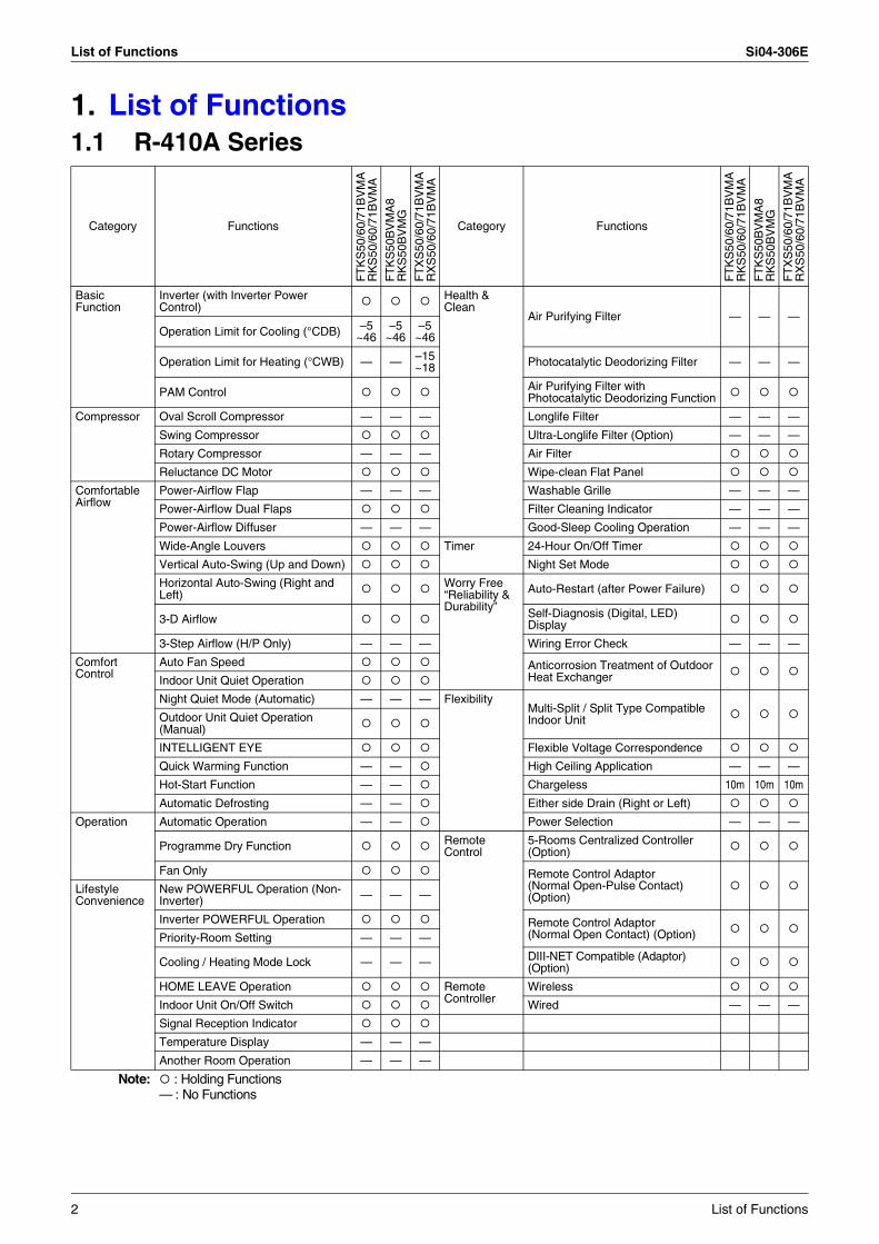
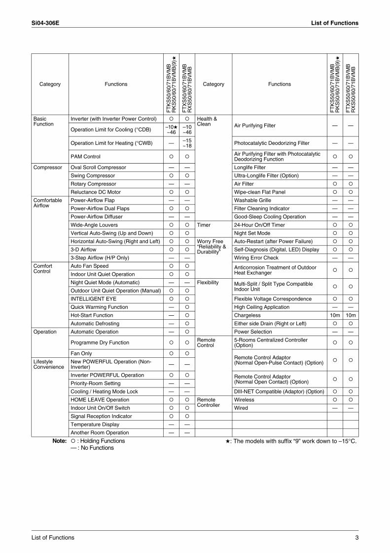
1. List of Functions1.1 R-410A Series
Category Functions
FT
KS
50/6
0/71
BV
MA
RK
S50
/60/
71B
VM
A
FT
KS
50B
VM
A8
RK
S50
BV
MG
FT
XS
50/6
0/71
BV
MA
RX
S50
/60/
71B
VM
A
Category Functions
FT
KS
50/6
0/71
BV
MA
RK
S50
/60/
71B
VM
A
FT
KS
50B
VM
A8
RK
S50
BV
MG
FT
XS
50/6
0/71
BV
MA
RX
S50
/60/
71B
VM
A
Basic Function
Inverter (with Inverter Power Control)
Health & Clean
Air Purifying Filter — — —Operation Limit for Cooling (°CDB) –5
~46–5
~46–5
~46
Operation Limit for Heating (°CWB) — — –15~18 Photocatalytic Deodorizing Filter — — —
PAM Control Air Purifying Filter with Photocatalytic Deodorizing Function
Compressor Oval Scroll Compressor — — — Longlife Filter — — —
Swing Compressor Ultra-Longlife Filter (Option) — — —
Rotary Compressor — — — Air Filter
Reluctance DC Motor Wipe-clean Flat Panel
Comfortable Airflow
Power-Airflow Flap — — — Washable Grille — — —
Power-Airflow Dual Flaps Filter Cleaning Indicator — — —
Power-Airflow Diffuser — — — Good-Sleep Cooling Operation — — —
Wide-Angle Louvers Timer 24-Hour On/Off Timer
Vertical Auto-Swing (Up and Down) Night Set Mode
Horizontal Auto-Swing (Right and Left)
Worry Free “Reliability & Durability”
Auto-Restart (after Power Failure)
3-D Airflow Self-Diagnosis (Digital, LED) Display
3-Step Airflow (H/P Only) — — — Wiring Error Check — — —
Comfort Control
Auto Fan Speed Anticorrosion Treatment of Outdoor Heat ExchangerIndoor Unit Quiet Operation
Night Quiet Mode (Automatic) — — — FlexibilityMulti-Split / Split Type Compatible Indoor UnitOutdoor Unit Quiet Operation
(Manual)
INTELLIGENT EYE Flexible Voltage Correspondence
Quick Warming Function — — High Ceiling Application — — —
Hot-Start Function — — Chargeless 10m 10m 10m
Automatic Defrosting — — Either side Drain (Right or Left)
Operation Automatic Operation — — Power Selection — — —
Programme Dry Function Remote Control
5-Rooms Centralized Controller (Option)
Fan Only Remote Control Adaptor(Normal Open-Pulse Contact) (Option)
Lifestyle Convenience
New POWERFUL Operation (Non-Inverter) — — —
Inverter POWERFUL Operation Remote Control Adaptor (Normal Open Contact) (Option)Priority-Room Setting — — —
Cooling / Heating Mode Lock — — — DIII-NET Compatible (Adaptor) (Option)
HOME LEAVE Operation Remote Controller
Wireless
Indoor Unit On/Off Switch Wired — — —
Signal Reception Indicator
Temperature Display — — —
Another Room Operation — — —
Note: : Holding Functions— : No Functions
2 List of Functions
Si04-306E List of Functions
Category Functions
FT
KS
50/6
0/71
BV
MB
RK
S50
/60/
71B
VM
B(9
)
FT
XS
50/6
0/71
BV
MB
RX
S50
/60/
71B
VM
B
Category Functions
FT
KS
50/6
0/71
BV
MB
RK
S50
/60/
71B
VM
B(9
)
FT
XS
50/6
0/71
BV
MB
RX
S50
/60/
71B
VM
B
Basic Function
Inverter (with Inverter Power Control) Health & Clean Air Purifying Filter — —
Operation Limit for Cooling (°CDB) –10~46
–10~46
Operation Limit for Heating (°CWB) — –15~18 Photocatalytic Deodorizing Filter — —
PAM Control Air Purifying Filter with Photocatalytic Deodorizing Function
Compressor Oval Scroll Compressor — — Longlife Filter — —
Swing Compressor Ultra-Longlife Filter (Option) — —
Rotary Compressor — — Air Filter
Reluctance DC Motor Wipe-clean Flat Panel
Comfortable Airflow
Power-Airflow Flap — — Washable Grille — —
Power-Airflow Dual Flaps Filter Cleaning Indicator — —
Power-Airflow Diffuser — — Good-Sleep Cooling Operation — —
Wide-Angle Louvers Timer 24-Hour On/Off Timer
Vertical Auto-Swing (Up and Down) Night Set Mode
Horizontal Auto-Swing (Right and Left) Worry Free “Reliability & Durability”
Auto-Restart (after Power Failure)
3-D Airflow Self-Diagnosis (Digital, LED) Display
3-Step Airflow (H/P Only) — — Wiring Error Check — —
Comfort Control
Auto Fan Speed Anticorrosion Treatment of Outdoor Heat ExchangerIndoor Unit Quiet Operation
Night Quiet Mode (Automatic) — — Flexibility Multi-Split / Split Type Compatible Indoor UnitOutdoor Unit Quiet Operation (Manual)
INTELLIGENT EYE Flexible Voltage Correspondence
Quick Warming Function — High Ceiling Application — —
Hot-Start Function — Chargeless 10m 10m
Automatic Defrosting — Either side Drain (Right or Left)
Operation Automatic Operation — Power Selection — —
Programme Dry Function Remote Control
5-Rooms Centralized Controller (Option)
Fan OnlyRemote Control Adaptor(Normal Open-Pulse Contact) (Option)Lifestyle
ConvenienceNew POWERFUL Operation (Non-Inverter) — —
Inverter POWERFUL Operation Remote Control Adaptor (Normal Open Contact) (Option)Priority-Room Setting — —
Cooling / Heating Mode Lock — — DIII-NET Compatible (Adaptor) (Option)
HOME LEAVE Operation Remote Controller
Wireless
Indoor Unit On/Off Switch Wired — —
Signal Reception Indicator
Temperature Display — —
Another Room Operation — —
Note: : Holding Functions— : No Functions
: The models with suffix “9” work down to –15°C.
List of Functions 3
List of Functions Si04-306E
Category Functions
FT
KS
50/6
0/71
BV
MB
RK
S50
/60/
71B
2VM
B
FT
XS
50/6
0/71
BV
MB
RX
S50
/60/
71B
2VM
B
Category Functions
FT
KS
50/6
0/71
BV
MB
RK
S50
/60/
71B
2VM
B
FT
XS
50/6
0/71
BV
MB
RX
S50
/60/
71B
2VM
B
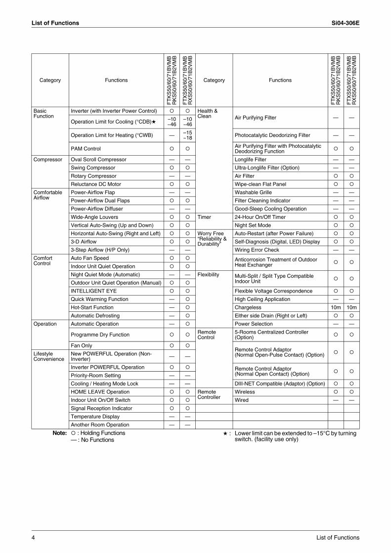
Basic Function
Inverter (with Inverter Power Control) Health & Clean Air Purifying Filter — —
Operation Limit for Cooling (°CDB) –10~46
–10~46
Operation Limit for Heating (°CWB) — –15~18 Photocatalytic Deodorizing Filter — —
PAM Control Air Purifying Filter with Photocatalytic Deodorizing Function
Compressor Oval Scroll Compressor — — Longlife Filter — —
Swing Compressor Ultra-Longlife Filter (Option) — —
Rotary Compressor — — Air Filter
Reluctance DC Motor Wipe-clean Flat Panel
Comfortable Airflow
Power-Airflow Flap — — Washable Grille — —
Power-Airflow Dual Flaps Filter Cleaning Indicator — —
Power-Airflow Diffuser — — Good-Sleep Cooling Operation — —
Wide-Angle Louvers Timer 24-Hour On/Off Timer
Vertical Auto-Swing (Up and Down) Night Set Mode
Horizontal Auto-Swing (Right and Left) Worry Free “Reliability & Durability”
Auto-Restart (after Power Failure)
3-D Airflow Self-Diagnosis (Digital, LED) Display
3-Step Airflow (H/P Only) — — Wiring Error Check — —
Comfort Control
Auto Fan Speed Anticorrosion Treatment of Outdoor Heat ExchangerIndoor Unit Quiet Operation
Night Quiet Mode (Automatic) — — Flexibility Multi-Split / Split Type Compatible Indoor UnitOutdoor Unit Quiet Operation (Manual)
INTELLIGENT EYE Flexible Voltage Correspondence
Quick Warming Function — High Ceiling Application — —
Hot-Start Function — Chargeless 10m 10m
Automatic Defrosting — Either side Drain (Right or Left)
Operation Automatic Operation — Power Selection — —
Programme Dry Function Remote Control
5-Rooms Centralized Controller (Option)
Fan OnlyRemote Control Adaptor(Normal Open-Pulse Contact) (Option)Lifestyle
ConvenienceNew POWERFUL Operation (Non-Inverter) — —
Inverter POWERFUL Operation Remote Control Adaptor (Normal Open Contact) (Option)Priority-Room Setting — —
Cooling / Heating Mode Lock — — DIII-NET Compatible (Adaptor) (Option)
HOME LEAVE Operation Remote Controller
Wireless
Indoor Unit On/Off Switch Wired — —
Signal Reception Indicator
Temperature Display — —
Another Room Operation — —
Note: : Holding Functions— : No Functions
: Lower limit can be extended to –15°C by turning switch. (facility use only)
4 List of Functions
Si04-306E List of Functions
Category Functions
FT
KS
71B
AV
MB
RK
S71
B3V
MB
FT
XS
71B
AV
MB
RX
S71
B3V
MB
Category Functions
FT
KS
71B
AV
MB
RK
S71
B3V
MB
FT
XS
71B
AV
MB
RX
S71
B3V
MB
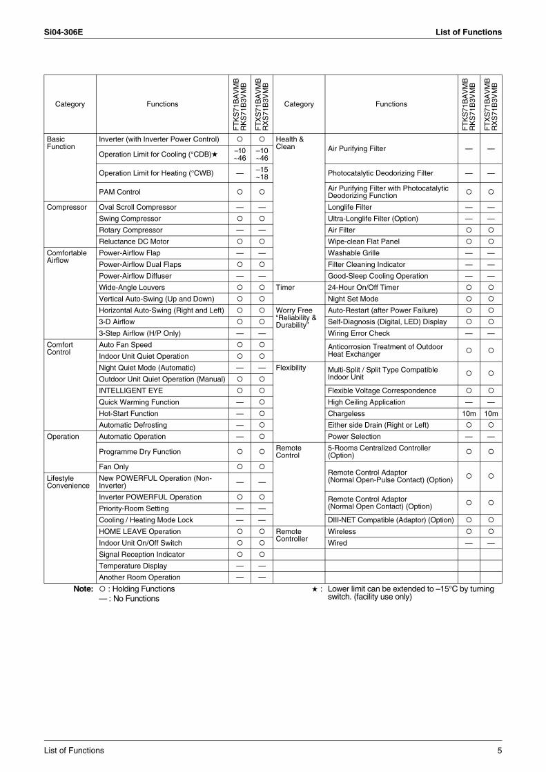
Basic Function
Inverter (with Inverter Power Control) Health & Clean Air Purifying Filter — —
Operation Limit for Cooling (°CDB) –10~46
–10~46
Operation Limit for Heating (°CWB) — –15~18 Photocatalytic Deodorizing Filter — —
PAM Control Air Purifying Filter with Photocatalytic Deodorizing Function
Compressor Oval Scroll Compressor — — Longlife Filter — —
Swing Compressor Ultra-Longlife Filter (Option) — —
Rotary Compressor — — Air Filter
Reluctance DC Motor Wipe-clean Flat Panel
Comfortable Airflow
Power-Airflow Flap — — Washable Grille — —
Power-Airflow Dual Flaps Filter Cleaning Indicator — —
Power-Airflow Diffuser — — Good-Sleep Cooling Operation — —
Wide-Angle Louvers Timer 24-Hour On/Off Timer
Vertical Auto-Swing (Up and Down) Night Set Mode
Horizontal Auto-Swing (Right and Left) Worry Free “Reliability & Durability”
Auto-Restart (after Power Failure)
3-D Airflow Self-Diagnosis (Digital, LED) Display
3-Step Airflow (H/P Only) — — Wiring Error Check — —
Comfort Control
Auto Fan Speed Anticorrosion Treatment of Outdoor Heat ExchangerIndoor Unit Quiet Operation
Night Quiet Mode (Automatic) — — Flexibility Multi-Split / Split Type Compatible Indoor UnitOutdoor Unit Quiet Operation (Manual)
INTELLIGENT EYE Flexible Voltage Correspondence
Quick Warming Function — High Ceiling Application — —
Hot-Start Function — Chargeless 10m 10m
Automatic Defrosting — Either side Drain (Right or Left)
Operation Automatic Operation — Power Selection — —
Programme Dry Function Remote Control
5-Rooms Centralized Controller (Option)
Fan OnlyRemote Control Adaptor(Normal Open-Pulse Contact) (Option)Lifestyle
ConvenienceNew POWERFUL Operation (Non-Inverter) — —
Inverter POWERFUL Operation Remote Control Adaptor (Normal Open Contact) (Option)Priority-Room Setting — —
Cooling / Heating Mode Lock — — DIII-NET Compatible (Adaptor) (Option)
HOME LEAVE Operation Remote Controller
Wireless
Indoor Unit On/Off Switch Wired — —
Signal Reception Indicator
Temperature Display — —
Another Room Operation — —
Note: : Holding Functions— : No Functions
: Lower limit can be extended to –15°C by turning switch. (facility use only)
List of Functions 5
List of Functions Si04-306E
Category Functions
AT
XS
50C
VM
BA
RX
S50
C(2
)VM
B
AT
XS
50D
VM
BA
RX
S50
C(2
)VM
B
Category Functions
AT
XS
50C
VM
BA
RX
S50
C(2
)VM
B
AT
XS
50D
VM
BA
RX
S50
C(2
)VM
B
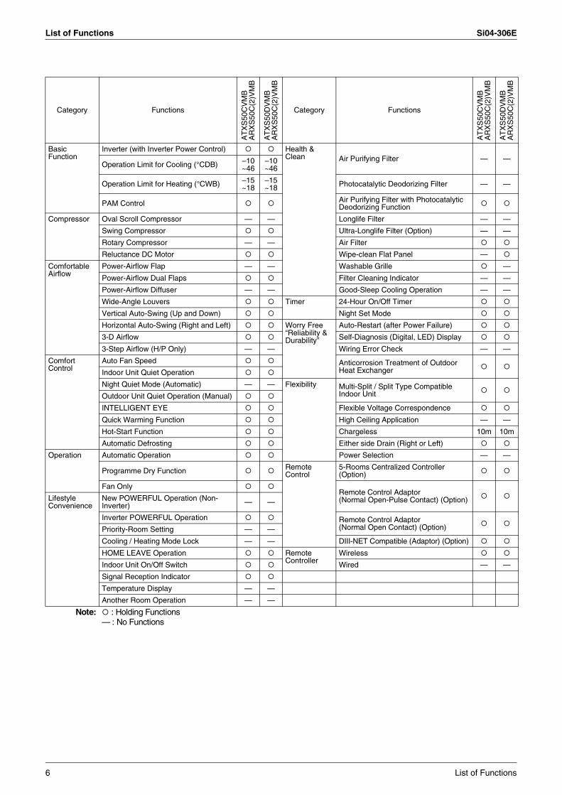
Basic Function
Inverter (with Inverter Power Control) Health & Clean Air Purifying Filter — —
Operation Limit for Cooling (°CDB) –10~46
–10~46
Operation Limit for Heating (°CWB) –15~18
–15~18 Photocatalytic Deodorizing Filter — —
PAM Control Air Purifying Filter with Photocatalytic Deodorizing Function
Compressor Oval Scroll Compressor — — Longlife Filter — —
Swing Compressor Ultra-Longlife Filter (Option) — —
Rotary Compressor — — Air Filter
Reluctance DC Motor Wipe-clean Flat Panel —
Comfortable Airflow
Power-Airflow Flap — — Washable Grille —
Power-Airflow Dual Flaps Filter Cleaning Indicator — —
Power-Airflow Diffuser — — Good-Sleep Cooling Operation — —
Wide-Angle Louvers Timer 24-Hour On/Off Timer
Vertical Auto-Swing (Up and Down) Night Set Mode
Horizontal Auto-Swing (Right and Left) Worry Free “Reliability & Durability”
Auto-Restart (after Power Failure)
3-D Airflow Self-Diagnosis (Digital, LED) Display
3-Step Airflow (H/P Only) — — Wiring Error Check — —
Comfort Control
Auto Fan Speed Anticorrosion Treatment of Outdoor Heat ExchangerIndoor Unit Quiet Operation
Night Quiet Mode (Automatic) — — Flexibility Multi-Split / Split Type Compatible Indoor UnitOutdoor Unit Quiet Operation (Manual)
INTELLIGENT EYE Flexible Voltage Correspondence
Quick Warming Function High Ceiling Application — —
Hot-Start Function Chargeless 10m 10m
Automatic Defrosting Either side Drain (Right or Left)
Operation Automatic Operation Power Selection — —
Programme Dry Function Remote Control
5-Rooms Centralized Controller (Option)
Fan OnlyRemote Control Adaptor(Normal Open-Pulse Contact) (Option)Lifestyle
ConvenienceNew POWERFUL Operation (Non-Inverter) — —
Inverter POWERFUL Operation Remote Control Adaptor (Normal Open Contact) (Option)Priority-Room Setting — —
Cooling / Heating Mode Lock — — DIII-NET Compatible (Adaptor) (Option)
HOME LEAVE Operation Remote Controller
Wireless
Indoor Unit On/Off Switch Wired — —
Signal Reception Indicator
Temperature Display — —
Another Room Operation — —
Note: : Holding Functions— : No Functions
6 List of Functions
Si04-306E List of Functions
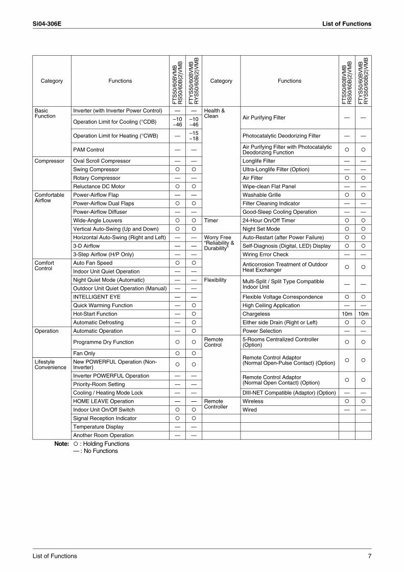
Category Functions
FT
S50
/60B
VM
BR
S50
/60B
(2)V
MB
FT
YS
50/6
0BV
MB
RY
S50
/60B
(2)V
MB
Category Functions
FT
S50
/60B
VM
BR
S50
/60B
(2)V
MB
FT
YS
50/6
0BV
MB
RY
S50
/60B
(2)V
MB
Basic Function
Inverter (with Inverter Power Control) — — Health & Clean Air Purifying Filter — —
Operation Limit for Cooling (°CDB) –10~46
–10~46
Operation Limit for Heating (°CWB) — –15~18 Photocatalytic Deodorizing Filter — —
PAM Control — — Air Purifying Filter with Photocatalytic Deodorizing Function
Compressor Oval Scroll Compressor — — Longlife Filter — —
Swing Compressor Ultra-Longlife Filter (Option) — —
Rotary Compressor — — Air Filter
Reluctance DC Motor Wipe-clean Flat Panel — —
Comfortable Airflow
Power-Airflow Flap — — Washable Grille
Power-Airflow Dual Flaps Filter Cleaning Indicator — —
Power-Airflow Diffuser — — Good-Sleep Cooling Operation — —
Wide-Angle Louvers Timer 24-Hour On/Off Timer
Vertical Auto-Swing (Up and Down) Night Set Mode
Horizontal Auto-Swing (Right and Left) — — Worry Free “Reliability & Durability”
Auto-Restart (after Power Failure)
3-D Airflow — — Self-Diagnosis (Digital, LED) Display
3-Step Airflow (H/P Only) — — Wiring Error Check — —
Comfort Control
Auto Fan Speed Anticorrosion Treatment of Outdoor Heat ExchangerIndoor Unit Quiet Operation — —
Night Quiet Mode (Automatic) — — Flexibility Multi-Split / Split Type Compatible Indoor Unit — —
Outdoor Unit Quiet Operation (Manual) — —
INTELLIGENT EYE — — Flexible Voltage Correspondence
Quick Warming Function — High Ceiling Application — —
Hot-Start Function — Chargeless 10m 10m
Automatic Defrosting — Either side Drain (Right or Left)
Operation Automatic Operation — Power Selection — —
Programme Dry Function Remote Control
5-Rooms Centralized Controller (Option)
Fan OnlyRemote Control Adaptor(Normal Open-Pulse Contact) (Option)Lifestyle
ConvenienceNew POWERFUL Operation (Non-Inverter)
Inverter POWERFUL Operation — — Remote Control Adaptor (Normal Open Contact) (Option)Priority-Room Setting — —
Cooling / Heating Mode Lock — — DIII-NET Compatible (Adaptor) (Option) — —
HOME LEAVE Operation — — Remote Controller
Wireless
Indoor Unit On/Off Switch Wired — —
Signal Reception Indicator
Temperature Display — —
Another Room Operation — —
Note: : Holding Functions— : No Functions
List of Functions 7
List of Functions Si04-306E
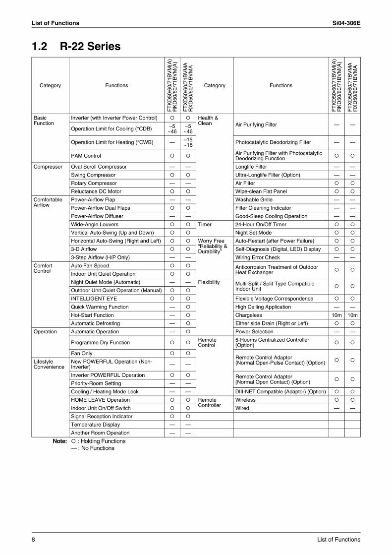
1.2 R-22 Series
Category Functions
FT
KD
50/6
0/71
BV
M(A
)R
KD
50/6
0/71
BV
M(A
)
FT
XD
50/6
0/71
BV
MA
RX
D50
/60/
71B
VM
A
Category Functions
FT
KD
50/6
0/71
BV
M(A
)R
KD
50/6
0/71
BV
M(A
)
FT
XD
50/6
0/71
BV
MA
RX
D50
/60/
71B
VM
A
Basic Function
Inverter (with Inverter Power Control) Health & Clean Air Purifying Filter — —
Operation Limit for Cooling (°CDB) –5~46
–5~46
Operation Limit for Heating (°CWB) — –15~18 Photocatalytic Deodorizing Filter — —
PAM Control Air Purifying Filter with Photocatalytic Deodorizing Function
Compressor Oval Scroll Compressor — — Longlife Filter — —
Swing Compressor Ultra-Longlife Filter (Option) — —
Rotary Compressor — — Air Filter
Reluctance DC Motor Wipe-clean Flat Panel
Comfortable Airflow
Power-Airflow Flap — — Washable Grille — —
Power-Airflow Dual Flaps Filter Cleaning Indicator — —
Power-Airflow Diffuser — — Good-Sleep Cooling Operation — —
Wide-Angle Louvers Timer 24-Hour On/Off Timer
Vertical Auto-Swing (Up and Down) Night Set Mode
Horizontal Auto-Swing (Right and Left) Worry Free “Reliability & Durability”
Auto-Restart (after Power Failure)
3-D Airflow Self-Diagnosis (Digital, LED) Display
3-Step Airflow (H/P Only) — — Wiring Error Check — —
Comfort Control
Auto Fan Speed Anticorrosion Treatment of Outdoor Heat ExchangerIndoor Unit Quiet Operation
Night Quiet Mode (Automatic) — — Flexibility Multi-Split / Split Type Compatible Indoor UnitOutdoor Unit Quiet Operation (Manual)
INTELLIGENT EYE Flexible Voltage Correspondence
Quick Warming Function — High Ceiling Application — —
Hot-Start Function — Chargeless 10m 10m
Automatic Defrosting — Either side Drain (Right or Left)
Operation Automatic Operation — Power Selection — —
Programme Dry Function Remote Control
5-Rooms Centralized Controller (Option)
Fan OnlyRemote Control Adaptor(Normal Open-Pulse Contact) (Option)Lifestyle
ConvenienceNew POWERFUL Operation (Non-Inverter) — —
Inverter POWERFUL Operation Remote Control Adaptor (Normal Open Contact) (Option)Priority-Room Setting — —
Cooling / Heating Mode Lock — — DIII-NET Compatible (Adaptor) (Option)
HOME LEAVE Operation Remote Controller
Wireless
Indoor Unit On/Off Switch Wired — —
Signal Reception Indicator
Temperature Display — —
Another Room Operation — —
Note: : Holding Functions— : No Functions
8 List of Functions
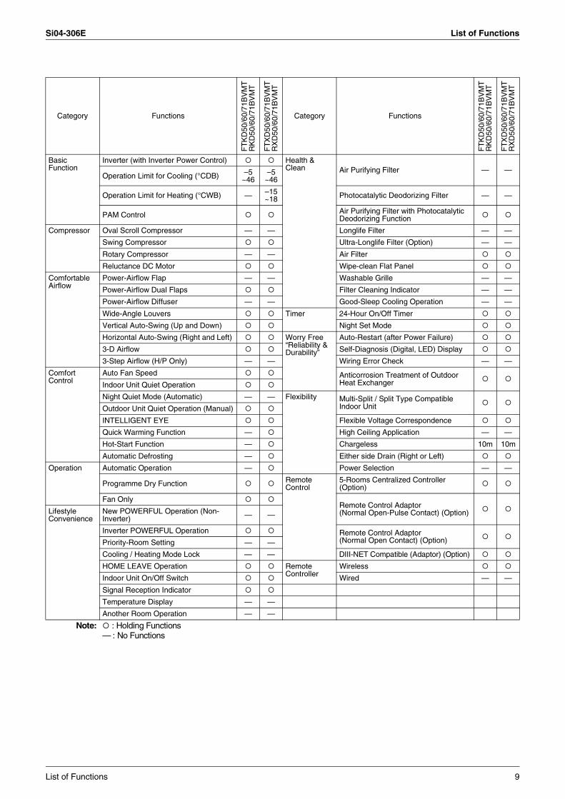
Si04-306E List of Functions
Category Functions
FT
KD
50/6
0/71
BV
MT
RK
D50
/60/
71B
VM
T
FT
XD
50/6
0/71
BV
MT
RX
D50
/60/
71B
VM
T
Category Functions
FT
KD
50/6
0/71
BV
MT
RK
D50
/60/
71B
VM
T
FT
XD
50/6
0/71
BV
MT
RX
D50
/60/
71B
VM
T
Basic Function
Inverter (with Inverter Power Control) Health & Clean Air Purifying Filter — —
Operation Limit for Cooling (°CDB) –5~46
–5~46
Operation Limit for Heating (°CWB) — –15~18 Photocatalytic Deodorizing Filter — —
PAM Control Air Purifying Filter with Photocatalytic Deodorizing Function
Compressor Oval Scroll Compressor — — Longlife Filter — —
Swing Compressor Ultra-Longlife Filter (Option) — —
Rotary Compressor — — Air Filter
Reluctance DC Motor Wipe-clean Flat Panel
Comfortable Airflow
Power-Airflow Flap — — Washable Grille — —
Power-Airflow Dual Flaps Filter Cleaning Indicator — —
Power-Airflow Diffuser — — Good-Sleep Cooling Operation — —
Wide-Angle Louvers Timer 24-Hour On/Off Timer
Vertical Auto-Swing (Up and Down) Night Set Mode
Horizontal Auto-Swing (Right and Left) Worry Free “Reliability & Durability”
Auto-Restart (after Power Failure)
3-D Airflow Self-Diagnosis (Digital, LED) Display
3-Step Airflow (H/P Only) — — Wiring Error Check — —
Comfort Control
Auto Fan Speed Anticorrosion Treatment of Outdoor Heat ExchangerIndoor Unit Quiet Operation
Night Quiet Mode (Automatic) — — Flexibility Multi-Split / Split Type Compatible Indoor UnitOutdoor Unit Quiet Operation (Manual)
INTELLIGENT EYE Flexible Voltage Correspondence
Quick Warming Function — High Ceiling Application — —
Hot-Start Function — Chargeless 10m 10m
Automatic Defrosting — Either side Drain (Right or Left)
Operation Automatic Operation — Power Selection — —
Programme Dry Function Remote Control
5-Rooms Centralized Controller (Option)
Fan OnlyRemote Control Adaptor(Normal Open-Pulse Contact) (Option)Lifestyle
ConvenienceNew POWERFUL Operation (Non-Inverter) — —
Inverter POWERFUL Operation Remote Control Adaptor (Normal Open Contact) (Option)Priority-Room Setting — —
Cooling / Heating Mode Lock — — DIII-NET Compatible (Adaptor) (Option)
HOME LEAVE Operation Remote Controller
Wireless
Indoor Unit On/Off Switch Wired — —
Signal Reception Indicator
Temperature Display — —
Another Room Operation — —
Note: : Holding Functions— : No Functions
List of Functions 9
List of Functions Si04-306E
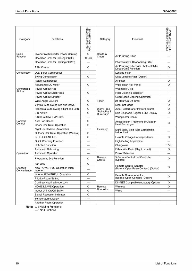
Category Functions
FT
KD
18/2
4/28
BV
MS
RK
D18
/24/
28B
VM
S
Category Functions
FT
KD
18/2
4/28
BV
MS
RK
D18
/24/
28B
VM
S
Basic Function
Inverter (with Inverter Power Control) Health & Clean Air Purifying Filter —
Operation Limit for Cooling (°CDB) 10~46
Operation Limit for Heating (°CWB) — Photocatalytic Deodorizing Filter —
PAM Control Air Purifying Filter with Photocatalytic Deodorizing Function
Compressor Oval Scroll Compressor — Longlife Filter —
Swing Compressor Ultra-Longlife Filter (Option) —
Rotary Compressor — Air Filter
Reluctance DC Motor Wipe-clean Flat Panel
Comfortable Airflow
Power-Airflow Flap — Washable Grille —
Power-Airflow Dual Flaps Filter Cleaning Indicator —
Power-Airflow Diffuser — Good-Sleep Cooling Operation —
Wide-Angle Louvers Timer 24-Hour On/Off Timer
Vertical Auto-Swing (Up and Down) Night Set Mode
Horizontal Auto-Swing (Right and Left) Worry Free “Reliability & Durability”
Auto-Restart (after Power Failure)
3-D Airflow Self-Diagnosis (Digital, LED) Display
3-Step Airflow (H/P Only) — Wiring Error Check —
Comfort Control
Auto Fan Speed Anticorrosion Treatment of Outdoor Heat ExchangerIndoor Unit Quiet Operation
Night Quiet Mode (Automatic) — Flexibility Multi-Split / Split Type Compatible Indoor Unit —
Outdoor Unit Quiet Operation (Manual)
INTELLIGENT EYE Flexible Voltage Correspondence
Quick Warming Function — High Ceiling Application —
Hot-Start Function — Chargeless 10m
Automatic Defrosting — Either side Drain (Right or Left)
Operation Automatic Operation — Power Selection —
Programme Dry Function Remote Control
5-Rooms Centralized Controller (Option)
Fan OnlyRemote Control Adaptor(Normal Open-Pulse Contact) (Option)Lifestyle
ConvenienceNew POWERFUL Operation (Non-Inverter) —
Inverter POWERFUL Operation Remote Control Adaptor (Normal Open Contact) (Option)Priority-Room Setting —
Cooling / Heating Mode Lock — DIII-NET Compatible (Adaptor) (Option)
HOME LEAVE Operation Remote Controller
Wireless
Indoor Unit On/Off Switch Wired —
Signal Reception Indicator
Temperature Display —
Another Room Operation —
Note: : Holding Functions— : No Functions
10 List of Functions
Si04-306E List of Functions
Category Functions
FT
XD
50B
V4
RX
D50
BV
4
Category Functions
FT
XD
50B
V4
RX
D50
BV
4
Basic Function
Inverter (with Inverter Power Control) Health & Clean Air Purifying Filter —
Operation Limit for Cooling (°CDB) –5~46
Operation Limit for Heating (°CWB) –15~18 Photocatalytic Deodorizing Filter —
PAM Control Air Purifying Filter with Photocatalytic Deodorizing Function
Compressor Oval Scroll Compressor — Longlife Filter —
Swing Compressor Ultra-Longlife Filter (Option) —
Rotary Compressor — Air Filter
Reluctance DC Motor Wipe-clean Flat Panel
Comfortable Airflow
Power-Airflow Flap — Washable Grille —
Power-Airflow Dual Flaps Filter Cleaning Indicator —
Power-Airflow Diffuser — Good-Sleep Cooling Operation —
Wide-Angle Louvers Timer 24-Hour On/Off Timer
Vertical Auto-Swing (Up and Down) Night Set Mode
Horizontal Auto-Swing (Right and Left) Worry Free “Reliability & Durability”
Auto-Restart (after Power Failure)
3-D Airflow Self-Diagnosis (Digital, LED) Display
3-Step Airflow (H/P Only) — Wiring Error Check —
Comfort Control
Auto Fan Speed Anticorrosion Treatment of Outdoor Heat ExchangerIndoor Unit Quiet Operation
Night Quiet Mode (Automatic) — Flexibility Multi-Split / Split Type Compatible Indoor Unit —
Outdoor Unit Quiet Operation (Manual)
INTELLIGENT EYE Flexible Voltage Correspondence —
Quick Warming Function High Ceiling Application —
Hot-Start Function Chargeless 10m
Automatic Defrosting Either side Drain (Right or Left)
Operation Automatic Operation Power Selection —
Programme Dry Function Remote Control
5-Rooms Centralized Controller (Option)
Fan OnlyRemote Control Adaptor(Normal Open-Pulse Contact) (Option)Lifestyle
ConvenienceNew POWERFUL Operation (Non-Inverter) —
Inverter POWERFUL Operation Remote Control Adaptor (Normal Open Contact) (Option)Priority-Room Setting —
Cooling / Heating Mode Lock — DIII-NET Compatible (Adaptor) (Option)
HOME LEAVE Operation Remote Controller
Wireless
Indoor Unit On/Off Switch Wired —
Signal Reception Indicator
Temperature Display —
Another Room Operation —
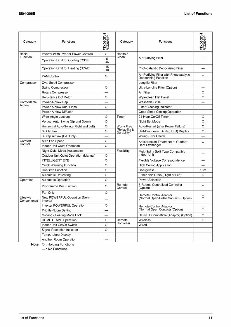
Note: : Holding Functions— : No Functions
List of Functions 11
List of Functions Si04-306E
Category Functions
FT
XD
80C
V4
RX
D80
CV
4
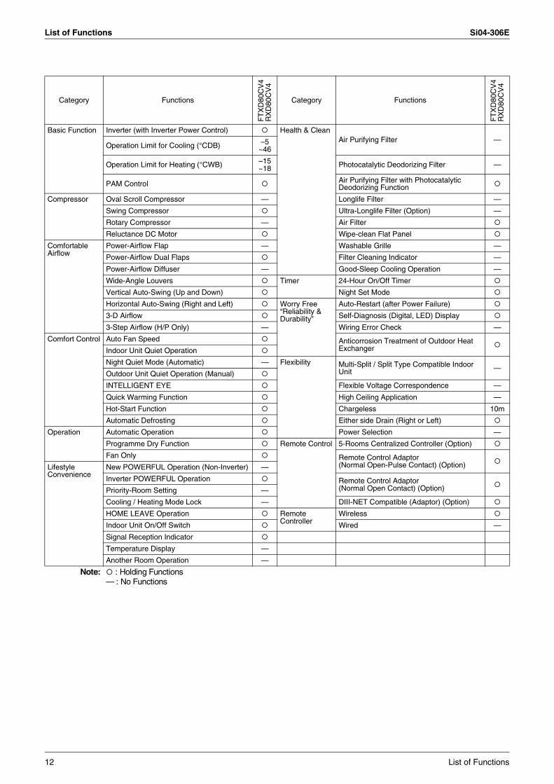
Category Functions
FT
XD
80C
V4
RX
D80
CV
4
Basic Function Inverter (with Inverter Power Control) Health & CleanAir Purifying Filter —
Operation Limit for Cooling (°CDB) –5~46
Operation Limit for Heating (°CWB) –15~18 Photocatalytic Deodorizing Filter —
PAM Control Air Purifying Filter with Photocatalytic Deodorizing Function
Compressor Oval Scroll Compressor — Longlife Filter —
Swing Compressor Ultra-Longlife Filter (Option) —
Rotary Compressor — Air Filter
Reluctance DC Motor Wipe-clean Flat Panel
Comfortable Airflow
Power-Airflow Flap — Washable Grille —
Power-Airflow Dual Flaps Filter Cleaning Indicator —
Power-Airflow Diffuser — Good-Sleep Cooling Operation —
Wide-Angle Louvers Timer 24-Hour On/Off Timer
Vertical Auto-Swing (Up and Down) Night Set Mode
Horizontal Auto-Swing (Right and Left) Worry Free “Reliability & Durability”
Auto-Restart (after Power Failure)
3-D Airflow Self-Diagnosis (Digital, LED) Display
3-Step Airflow (H/P Only) — Wiring Error Check —
Comfort Control Auto Fan Speed Anticorrosion Treatment of Outdoor Heat ExchangerIndoor Unit Quiet Operation
Night Quiet Mode (Automatic) — Flexibility Multi-Split / Split Type Compatible Indoor Unit —
Outdoor Unit Quiet Operation (Manual)
INTELLIGENT EYE Flexible Voltage Correspondence —
Quick Warming Function High Ceiling Application —
Hot-Start Function Chargeless 10m
Automatic Defrosting Either side Drain (Right or Left)
Operation Automatic Operation Power Selection —
Programme Dry Function Remote Control 5-Rooms Centralized Controller (Option)
Fan Only Remote Control Adaptor(Normal Open-Pulse Contact) (Option)Lifestyle
ConvenienceNew POWERFUL Operation (Non-Inverter) —
Inverter POWERFUL Operation Remote Control Adaptor (Normal Open Contact) (Option)Priority-Room Setting —
Cooling / Heating Mode Lock — DIII-NET Compatible (Adaptor) (Option)
HOME LEAVE Operation Remote Controller
Wireless
Indoor Unit On/Off Switch Wired —
Signal Reception Indicator
Temperature Display —
Another Room Operation —
Note: : Holding Functions— : No Functions
12 List of Functions
Si04-306E
Specifications 13
Part 2Specifications
1. Specifications ........................................................................................141.1 Cooling Only - R-410A Series ................................................................141.2 Cooling Only - R-22 Series.....................................................................191.3 Heat Pump - R-410A Series...................................................................231.4 Heat Pump - R-22 Series .......................................................................30
Specifications Si04-306E
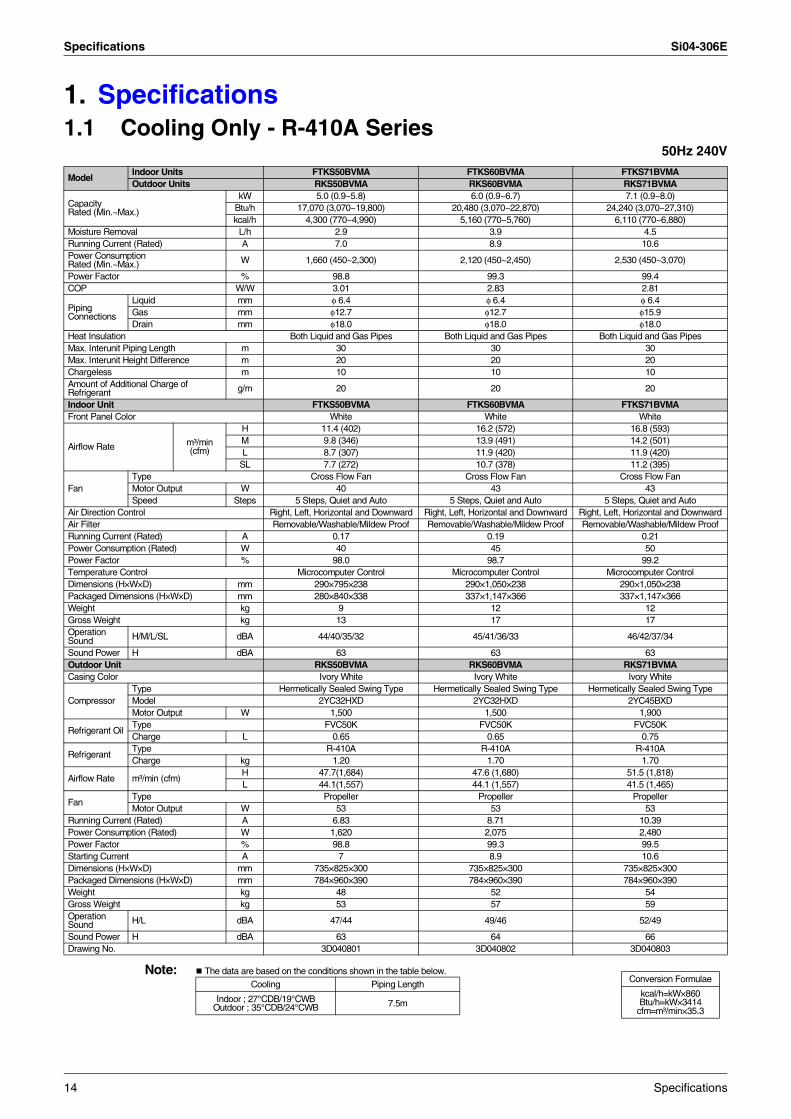
1. Specifications1.1 Cooling Only - R-410A Series
50Hz 240V
Note: The data are based on the conditions shown in the table below.
ModelIndoor Units FTKS50BVMA FTKS60BVMA FTKS71BVMAOutdoor Units RKS50BVMA RKS60BVMA RKS71BVMA
Capacity Rated (Min.~Max.)
kW 5.0 (0.9~5.8) 6.0 (0.9~6.7) 7.1 (0.9~8.0)Btu/h 17,070 (3,070~19,800) 20,480 (3,070~22,870) 24,240 (3,070~27,310)kcal/h 4,300 (770~4,990) 5,160 (770~5,760) 6,110 (770~6,880)
Moisture Removal L/h 2.9 3.9 4.5Running Current (Rated) A 7.0 8.9 10.6Power Consumption Rated (Min.~Max.) W 1,660 (450~2,300) 2,120 (450~2,450) 2,530 (450~3,070)
Power Factor % 98.8 99.3 99.4COP W/W 3.01 2.83 2.81
Piping Connections
Liquid mm φ 6.4 φ 6.4 φ 6.4Gas mm φ12.7 φ12.7 φ15.9Drain mm φ18.0 φ18.0 φ18.0
Heat Insulation Both Liquid and Gas Pipes Both Liquid and Gas Pipes Both Liquid and Gas PipesMax. Interunit Piping Length m 30 30 30Max. Interunit Height Difference m 20 20 20Chargeless m 10 10 10Amount of Additional Charge ofRefrigerant g/m 20 20 20
Indoor Unit FTKS50BVMA FTKS60BVMA FTKS71BVMAFront Panel Color White White White
Airflow Rate m³/min(cfm)
H 11.4 (402) 16.2 (572) 16.8 (593)M 9.8 (346) 13.9 (491) 14.2 (501)L 8.7 (307) 11.9 (420) 11.9 (420)
SL 7.7 (272) 10.7 (378) 11.2 (395)
FanType Cross Flow Fan Cross Flow Fan Cross Flow FanMotor Output W 40 43 43Speed Steps 5 Steps, Quiet and Auto 5 Steps, Quiet and Auto 5 Steps, Quiet and Auto
Air Direction Control Right, Left, Horizontal and Downward Right, Left, Horizontal and Downward Right, Left, Horizontal and DownwardAir Filter Removable/Washable/Mildew Proof Removable/Washable/Mildew Proof Removable/Washable/Mildew ProofRunning Current (Rated) A 0.17 0.19 0.21Power Consumption (Rated) W 40 45 50Power Factor % 98.0 98.7 99.2Temperature Control Microcomputer Control Microcomputer Control Microcomputer ControlDimensions (H×W×D) mm 290×795×238 290×1,050×238 290×1,050×238Packaged Dimensions (H×W×D) mm 280×840×338 337×1,147×366 337×1,147×366Weight kg 9 12 12Gross Weight kg 13 17 17Operation Sound H/M/L/SL dBA 44/40/35/32 45/41/36/33 46/42/37/34
Sound Power H dBA 63 63 63Outdoor Unit RKS50BVMA RKS60BVMA RKS71BVMACasing Color Ivory White Ivory White Ivory White
CompressorType Hermetically Sealed Swing Type Hermetically Sealed Swing Type Hermetically Sealed Swing TypeModel 2YC32HXD 2YC32HXD 2YC45BXDMotor Output W 1,500 1,500 1,900
Refrigerant OilType FVC50K FVC50K FVC50KCharge L 0.65 0.65 0.75
RefrigerantType R-410A R-410A R-410ACharge kg 1.20 1.70 1.70
Airflow Rate m³/min (cfm)H 47.7(1,684) 47.6 (1,680) 51.5 (1,818)L 44.1(1,557) 44.1 (1,557) 41.5 (1,465)
FanType Propeller Propeller PropellerMotor Output W 53 53 53
Running Current (Rated) A 6.83 8.71 10.39Power Consumption (Rated) W 1,620 2,075 2,480Power Factor % 98.8 99.3 99.5Starting Current A 7 8.9 10.6Dimensions (H×W×D) mm 735×825×300 735×825×300 735×825×300Packaged Dimensions (H×W×D) mm 784×960×390 784×960×390 784×960×390Weight kg 48 52 54Gross Weight kg 53 57 59Operation Sound H/L dBA 47/44 49/46 52/49
Sound Power H dBA 63 64 66Drawing No. 3D040801 3D040802 3D040803
Conversion Formulae
kcal/h=kW×860Btu/h=kW×3414
cfm=m³/min×35.3
Cooling Piping Length
Indoor ; 27°CDB/19°CWB Outdoor ; 35°CDB/24°CWB 7.5m
14 Specifications
Si04-306E Specifications
50Hz 230V
Note: The data are based on the conditions shown in the table below.
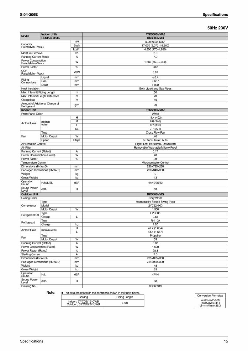
ModelIndoor Units FTKS50BVMA8Outdoor Units RKS50BVMG
Capacity Rated (Min.~Max.)
kW 5.00 (0.90~5.80)Btu/h 17,070 (3,070~19,800)kcal/h 4,300 (770~4,990)
Moisture Removal I/h 2.9Running Current Rated A 7.0Power Consumption Rated (Min.~Max.) W 1,660 (450~2,300)
Power Factor % 98.8COPRated (Min.~Max.) W/W 3.01
Piping Connections
Liquid mm φ 6.4Gas mm φ12.7Drain mm φ18.0
Heat Insulation Both Liquid and Gas PipesMax. Interunit Piping Length m 30Max. Interunit Height Difference m 20Chargeless m 10Amount of Additional Charge ofRefrigerant g/m 20
Indoor Unit FTKS50BVMA8Front Panel Color White
Airflow Rate m³/min(cfm)
H 11.4 (402)M 9.8 (346)L 8.7 (306)
SL 7.7 (271)
FanType Cross Flow FanMotor Output W 40Speed Steps 5 Steps, Quiet, Auto
Air Direction Control Right, Left, Horizontal, DownwardAir Filter Removable/Washable/Mildew ProofRunning Current (Rated) A 0.17Power Consumption (Rated) W 40Power Factor % 98Temperature Control Microcomputer ControlDimensions (H×W×D) mm 290×795×238Packaged Dimensions (H×W×D) mm 280×840×338Weight kg 9Gross Weight kg 13Operation Sound H/M/L/SL dBA 44/40/35/32
Sound Power Level dBA H 63
Outdoor Unit RKS50BVMGCasing Color Ivory White
CompressorType Hermetically Sealed Swing TypeModel 2YC32HXDMotor Output W 1,500
Refrigerant OilType FVC50KCharge L 0.65
RefrigerantType R-410ACharge kg 1.20
Airflow Rate m³/min (cfm)H 47.7 (1,684)L 44.1 (1,557)
FanType PropellerMotor Output W 53
Running Current (Rated) A 6.83Power Consumption (Rated) W 1,620Power Factor (Rated) % 98.8Starting Current A 7.0Dimensions (H×W×D) mm 735×825×300Packaged Dimensions (H×W×D) mm 784×960×390Weight kg 48Gross Weight kg 53Operation Sound H/L dBA 47/44
Sound Power Level dBA H 63
Drawing No. 3D060919
Conversion Formulae
kcal/h=kW×860Btu/h=kW×3414
cfm=m³/min×35.3
Cooling Piping Length
Indoor ; 27°CDB/19°CWB Outdoor ; 35°CDB/24°CWB 7.5m
Specifications 15
Specifications Si04-306E
50Hz 230V
Note: The data are based on the conditions shown in the table below.
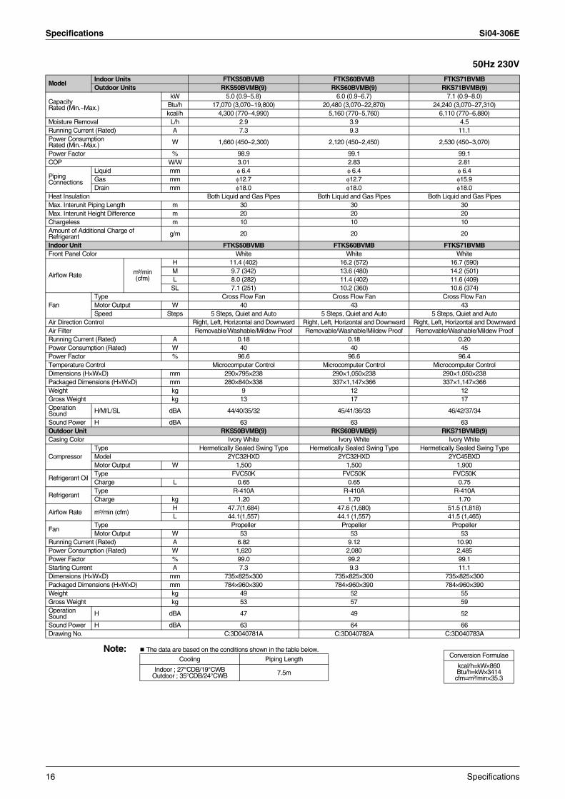
ModelIndoor Units FTKS50BVMB FTKS60BVMB FTKS71BVMBOutdoor Units RKS50BVMB(9) RKS60BVMB(9) RKS71BVMB(9)
Capacity Rated (Min.~Max.)
kW 5.0 (0.9~5.8) 6.0 (0.9~6.7) 7.1 (0.9~8.0)Btu/h 17,070 (3,070~19,800) 20,480 (3,070~22,870) 24,240 (3,070~27,310)kcal/h 4,300 (770~4,990) 5,160 (770~5,760) 6,110 (770~6,880)
Moisture Removal L/h 2.9 3.9 4.5Running Current (Rated) A 7.3 9.3 11.1Power Consumption Rated (Min.~Max.) W 1,660 (450~2,300) 2,120 (450~2,450) 2,530 (450~3,070)
Power Factor % 98.9 99.1 99.1COP W/W 3.01 2.83 2.81
Piping Connections
Liquid mm φ 6.4 φ 6.4 φ 6.4Gas mm φ12.7 φ12.7 φ15.9Drain mm φ18.0 φ18.0 φ18.0
Heat Insulation Both Liquid and Gas Pipes Both Liquid and Gas Pipes Both Liquid and Gas PipesMax. Interunit Piping Length m 30 30 30Max. Interunit Height Difference m 20 20 20Chargeless m 10 10 10Amount of Additional Charge ofRefrigerant g/m 20 20 20
Indoor Unit FTKS50BVMB FTKS60BVMB FTKS71BVMBFront Panel Color White White White
Airflow Rate m³/min(cfm)
H 11.4 (402) 16.2 (572) 16.7 (590)M 9.7 (342) 13.6 (480) 14.2 (501)L 8.0 (282) 11.4 (402) 11.6 (409)
SL 7.1 (251) 10.2 (360) 10.6 (374)
FanType Cross Flow Fan Cross Flow Fan Cross Flow FanMotor Output W 40 43 43Speed Steps 5 Steps, Quiet and Auto 5 Steps, Quiet and Auto 5 Steps, Quiet and Auto
Air Direction Control Right, Left, Horizontal and Downward Right, Left, Horizontal and Downward Right, Left, Horizontal and DownwardAir Filter Removable/Washable/Mildew Proof Removable/Washable/Mildew Proof Removable/Washable/Mildew ProofRunning Current (Rated) A 0.18 0.18 0.20Power Consumption (Rated) W 40 40 45Power Factor % 96.6 96.6 96.4Temperature Control Microcomputer Control Microcomputer Control Microcomputer ControlDimensions (H×W×D) mm 290×795×238 290×1,050×238 290×1,050×238Packaged Dimensions (H×W×D) mm 280×840×338 337×1,147×366 337×1,147×366Weight kg 9 12 12Gross Weight kg 13 17 17Operation Sound H/M/L/SL dBA 44/40/35/32 45/41/36/33 46/42/37/34
Sound Power H dBA 63 63 63Outdoor Unit RKS50BVMB(9) RKS60BVMB(9) RKS71BVMB(9)Casing Color Ivory White Ivory White Ivory White
CompressorType Hermetically Sealed Swing Type Hermetically Sealed Swing Type Hermetically Sealed Swing TypeModel 2YC32HXD 2YC32HXD 2YC45BXDMotor Output W 1,500 1,500 1,900
Refrigerant OilType FVC50K FVC50K FVC50KCharge L 0.65 0.65 0.75
RefrigerantType R-410A R-410A R-410ACharge kg 1.20 1.70 1.70
Airflow Rate m³/min (cfm)H 47.7(1,684) 47.6 (1,680) 51.5 (1,818)L 44.1(1,557) 44.1 (1,557) 41.5 (1,465)
FanType Propeller Propeller PropellerMotor Output W 53 53 53
Running Current (Rated) A 6.82 9.12 10.90Power Consumption (Rated) W 1,620 2,080 2,485Power Factor % 99.0 99.2 99.1Starting Current A 7.3 9.3 11.1Dimensions (H×W×D) mm 735×825×300 735×825×300 735×825×300Packaged Dimensions (H×W×D) mm 784×960×390 784×960×390 784×960×390Weight kg 49 52 55Gross Weight kg 53 57 59Operation Sound H dBA 47 49 52
Sound Power H dBA 63 64 66Drawing No. C:3D040781A C:3D040782A C:3D040783A
Conversion Formulae
kcal/h=kW×860Btu/h=kW×3414
cfm=m³/min×35.3
Cooling Piping Length
Indoor ; 27°CDB/19°CWB Outdoor ; 35°CDB/24°CWB 7.5m
16 Specifications
Si04-306E Specifications
50Hz 230V
Note: The data are based on the conditions shown in the table below.
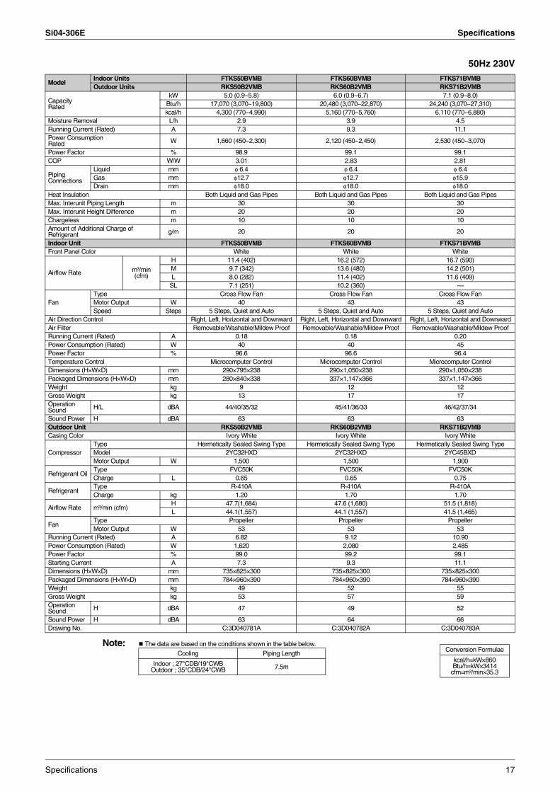
ModelIndoor Units FTKS50BVMB FTKS60BVMB FTKS71BVMBOutdoor Units RKS50B2VMB RKS60B2VMB RKS71B2VMB
Capacity Rated
kW 5.0 (0.9~5.8) 6.0 (0.9~6.7) 7.1 (0.9~8.0)Btu/h 17,070 (3,070~19,800) 20,480 (3,070~22,870) 24,240 (3,070~27,310)kcal/h 4,300 (770~4,990) 5,160 (770~5,760) 6,110 (770~6,880)
Moisture Removal L/h 2.9 3.9 4.5Running Current (Rated) A 7.3 9.3 11.1Power Consumption Rated W 1,660 (450~2,300) 2,120 (450~2,450) 2,530 (450~3,070)
Power Factor % 98.9 99.1 99.1COP W/W 3.01 2.83 2.81
Piping Connections
Liquid mm φ 6.4 φ 6.4 φ 6.4Gas mm φ12.7 φ12.7 φ15.9Drain mm φ18.0 φ18.0 φ18.0
Heat Insulation Both Liquid and Gas Pipes Both Liquid and Gas Pipes Both Liquid and Gas PipesMax. Interunit Piping Length m 30 30 30Max. Interunit Height Difference m 20 20 20Chargeless m 10 10 10Amount of Additional Charge ofRefrigerant g/m 20 20 20
Indoor Unit FTKS50BVMB FTKS60BVMB FTKS71BVMBFront Panel Color White White White
Airflow Rate m³/min(cfm)
H 11.4 (402) 16.2 (572) 16.7 (590)M 9.7 (342) 13.6 (480) 14.2 (501)L 8.0 (282) 11.4 (402) 11.6 (409)
SL 7.1 (251) 10.2 (360) —
FanType Cross Flow Fan Cross Flow Fan Cross Flow FanMotor Output W 40 43 43Speed Steps 5 Steps, Quiet and Auto 5 Steps, Quiet and Auto 5 Steps, Quiet and Auto
Air Direction Control Right, Left, Horizontal and Downward Right, Left, Horizontal and Downward Right, Left, Horizontal and DownwardAir Filter Removable/Washable/Mildew Proof Removable/Washable/Mildew Proof Removable/Washable/Mildew ProofRunning Current (Rated) A 0.18 0.18 0.20Power Consumption (Rated) W 40 40 45Power Factor % 96.6 96.6 96.4Temperature Control Microcomputer Control Microcomputer Control Microcomputer ControlDimensions (H×W×D) mm 290×795×238 290×1,050×238 290×1,050×238Packaged Dimensions (H×W×D) mm 280×840×338 337×1,147×366 337×1,147×366Weight kg 9 12 12Gross Weight kg 13 17 17Operation Sound H/L dBA 44/40/35/32 45/41/36/33 46/42/37/34
Sound Power H dBA 63 63 63Outdoor Unit RKS50B2VMB RKS60B2VMB RKS71B2VMBCasing Color Ivory White Ivory White Ivory White
CompressorType Hermetically Sealed Swing Type Hermetically Sealed Swing Type Hermetically Sealed Swing TypeModel 2YC32HXD 2YC32HXD 2YC45BXDMotor Output W 1,500 1,500 1,900
Refrigerant OilType FVC50K FVC50K FVC50KCharge L 0.65 0.65 0.75
RefrigerantType R-410A R-410A R-410ACharge kg 1.20 1.70 1.70
Airflow Rate m³/min (cfm)H 47.7(1,684) 47.6 (1,680) 51.5 (1,818)L 44.1(1,557) 44.1 (1,557) 41.5 (1,465)
FanType Propeller Propeller PropellerMotor Output W 53 53 53
Running Current (Rated) A 6.82 9.12 10.90Power Consumption (Rated) W 1,620 2,080 2,485Power Factor % 99.0 99.2 99.1Starting Current A 7.3 9.3 11.1Dimensions (H×W×D) mm 735×825×300 735×825×300 735×825×300Packaged Dimensions (H×W×D) mm 784×960×390 784×960×390 784×960×390Weight kg 49 52 55Gross Weight kg 53 57 59Operation Sound H dBA 47 49 52
Sound Power H dBA 63 64 66Drawing No. C:3D040781A C:3D040782A C:3D040783A
Conversion Formulae
kcal/h=kW×860Btu/h=kW×3414
cfm=m³/min×35.3
Cooling Piping Length
Indoor ; 27°CDB/19°CWB Outdoor ; 35°CDB/24°CWB 7.5m
Specifications 17
Specifications Si04-306E
50Hz 230V
Note: The data are based on the conditions shown in the table below.
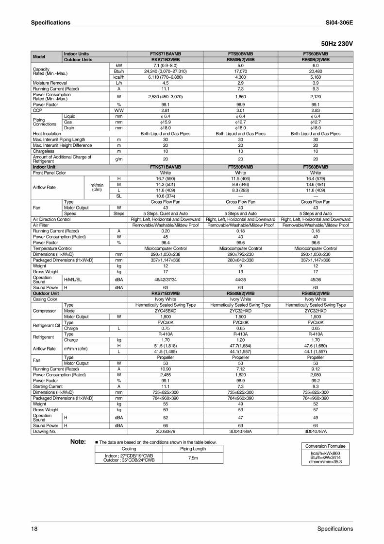
ModelIndoor Units FTKS71BAVMB FTS50BVMB FTS60BVMBOutdoor Units RKS71B3VMB RS50B(2)VMB RS60B(2)VMB
Capacity Rated (Min.~Max.)
kW 7.1 (0.9~8.0) 5.0 6.0Btu/h 24,240 (3,070~27,310) 17,070 20,480kcal/h 6,110 (770~6,880) 4,300 5,160
Moisture Removal L/h 4.5 2.9 3.9Running Current (Rated) A 11.1 7.3 9.3Power Consumption Rated (Min.~Max.) W 2,530 (450~3,070) 1,660 2,120
Power Factor % 99.1 98.9 99.1COP W/W 2.81 3.01 2.83
Piping Connections
Liquid mm φ 6.4 φ 6.4 φ 6.4Gas mm φ15.9 φ12.7 φ12.7Drain mm φ18.0 φ18.0 φ18.0
Heat Insulation Both Liquid and Gas Pipes Both Liquid and Gas Pipes Both Liquid and Gas PipesMax. Interunit Piping Length m 30 30 30Max. Interunit Height Difference m 20 20 20Chargeless m 10 10 10Amount of Additional Charge ofRefrigerant g/m 20 20 20
Indoor Unit FTKS71BAVMB FTS50BVMB FTS60BVMBFront Panel Color White White White
Airflow Rate m³/min(cfm)
H 16.7 (590) 11.5 (406) 16.4 (579)M 14.2 (501) 9.8 (346) 13.6 (491)L 11.6 (409) 8.3 (293) 11.6 (409)
SL 10.6 (374) — —
FanType Cross Flow Fan Cross Flow Fan Cross Flow FanMotor Output W 43 40 43Speed Steps 5 Steps, Quiet and Auto 5 Steps and Auto 5 Steps and Auto
Air Direction Control Right, Left, Horizontal and Downward Right, Left, Horizontal and Downward Right, Left, Horizontal and DownwardAir Filter Removable/Washable/Mildew Proof Removable/Washable/Mildew Proof Removable/Washable/Mildew ProofRunning Current (Rated) A 0.20 0.18 0.18Power Consumption (Rated) W 45 40 40Power Factor % 96.4 96.6 96.6Temperature Control Microcomputer Control Microcomputer Control Microcomputer ControlDimensions (H×W×D) mm 290×1,050×238 290×795×230 290×1,050×230Packaged Dimensions (H×W×D) mm 337×1,147×366 280×840×338 337×1,147×366Weight kg 12 9 12Gross Weight kg 17 13 17Operation Sound H/M/L/SL dBA 46/42/37/34 44/35 45/36
Sound Power H dBA 63 63 63Outdoor Unit RKS71B3VMB RS50B(2)VMB RS60B(2)VMBCasing Color Ivory White Ivory White Ivory White
CompressorType Hermetically Sealed Swing Type Hermetically Sealed Swing Type Hermetically Sealed Swing TypeModel 2YC45BXD 2YC32HXD 2YC32HXDMotor Output W 1,900 1,500 1,500
Refrigerant OilType FVC50K FVC50K FVC50KCharge L 0.75 0.65 0.65
RefrigerantType R-410A R-410A R-410ACharge kg 1.70 1.20 1.70
Airflow Rate m³/min (cfm)H 51.5 (1,818) 47.7(1,684) 47.6 (1,680)L 41.5 (1,465) 44.1(1,557) 44.1 (1,557)
FanType Propeller Propeller PropellerMotor Output W 53 53 53
Running Current (Rated) A 10.90 7.12 9.12Power Consumption (Rated) W 2,485 1,620 2,080Power Factor % 99.1 98.9 99.2Starting Current A 11.1 7.3 9.3Dimensions (H×W×D) mm 735×825×300 735×825×300 735×825×300Packaged Dimensions (H×W×D) mm 784×960×390 784×960×390 784×960×390Weight kg 55 49 52Gross Weight kg 59 53 57Operation Sound H dBA 52 47 49
Sound Power H dBA 66 63 64Drawing No. 3D050879 3D040786A 3D040787A
Conversion Formulae
kcal/h=kW×860Btu/h=kW×3414
cfm=m³/min×35.3
Cooling Piping Length
Indoor ; 27°CDB/19°CWB Outdoor ; 35°CDB/24°CWB 7.5m
18 Specifications
Si04-306E Specifications
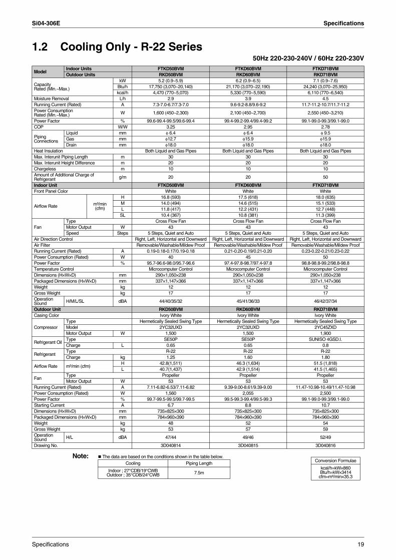
1.2 Cooling Only - R-22 Series50Hz 220-230-240V / 60Hz 220-230V
Note: The data are based on the conditions shown in the table below.
ModelIndoor Units FTKD50BVM FTKD60BVM FTKD71BVMOutdoor Units RKD50BVM RKD60BVM RKD71BVM
Capacity Rated (Min.~Max.)
kW 5.2 (0.9~5.9) 6.2 (0.9~6.5) 7.1 (0.9~7.6)Btu/h 17,750 (3,070~20,140) 21,170 (3,070~22,190) 24,240 (3,070~25,950)kcal/h 4,470 (770~5,070) 5,330 (770~5,590) 6,110 (770~6,540)
Moisture Removal L/h 2.9 3.9 4.5Running Current (Rated) A 7.3-7.0-6.7/7.3-7.0 9.6-9.2-8.8/9.6-9.2 11.7-11.2-10.7/11.7-11.2Power Consumption Rated (Min.~Max.) W 1,600 (450~2,300) 2,100 (450~2,700) 2,550 (450~3,210)
Power Factor % 99.6-99.4-99.5/99.6-99.4 99.4-99.2-99.4/99.4-99.2 99.1-99.0-99.3/99.1-99.0COP W/W 3.25 2.95 2.78
Piping Connections
Liquid mm φ 6.4 φ 6.4 φ 9.5Gas mm φ12.7 φ15.9 φ15.9Drain mm φ18.0 φ18.0 φ18.0
Heat Insulation Both Liquid and Gas Pipes Both Liquid and Gas Pipes Both Liquid and Gas PipesMax. Interunit Piping Length m 30 30 30Max. Interunit Height Difference m 20 20 20Chargeless m 10 10 10Amount of Additional Charge ofRefrigerant g/m 20 20 50
Indoor Unit FTKD50BVM FTKD60BVM FTKD71BVMFront Panel Color White White White
Airflow Rate m³/min(cfm)
H 16.8 (593) 17.5 (618) 18.0 (635)M 14.0 (494) 14.6 (515) 15.1 (533)L 11.8 (417) 12.2 (431) 12.7 (448)
SL 10.4 (367) 10.8 (381) 11.3 (399)
FanType Cross Flow Fan Cross Flow Fan Cross Flow FanMotor Output W 43 43 43Speed Steps 5 Steps, Quiet and Auto 5 Steps, Quiet and Auto 5 Steps, Quiet and Auto
Air Direction Control Right, Left, Horizontal and Downward Right, Left, Horizontal and Downward Right, Left, Horizontal and DownwardAir Filter Removable/Washable/Mildew Proof Removable/Washable/Mildew Proof Removable/Washable/Mildew ProofRunning Current (Rated) A 0.19-0.18-0.17/0.19-0.18 0.21-0.20-0.19/0.21-0.20 0.23-0.22-0.21/0.23-0.22Power Consumption (Rated) W 40 45 50Power Factor % 95.7-96.6-98.0/95.7-96.6 97.4-97.8-98.7/97.4-97.8 98.8-98.8-99.2/98.8-98.8Temperature Control Microcomputer Control Microcomputer Control Microcomputer ControlDimensions (H×W×D) mm 290×1,050×238 290×1,050×238 290×1,050×238Packaged Dimensions (H×W×D) mm 337×1,147×366 337×1,147×366 337×1,147×366Weight kg 12 12 12Gross Weight kg 17 17 17Operation Sound H/M/L/SL dBA 44/40/35/32 45/41/36/33 46/42/37/34
Outdoor Unit RKD50BVM RKD60BVM RKD71BVMCasing Color Ivory White Ivory White Ivory White
CompressorType Hermetically Sealed Swing Type Hermetically Sealed Swing Type Hermetically Sealed Swing TypeModel 2YC32UXD 2YC32UXD 2YC45ZXDMotor Output W 1,500 1,500 1,900
Refrigerant OilType SE50P SE50P SUNISO 4GSD.I.Charge L 0.65 0.65 0.8
RefrigerantType R-22 R-22 R-22Charge kg 1.25 1.60 1.80
Airflow Rate m³/min (cfm)H 42.8(1,511) 46.3 (1,634) 51.5 (1,818)L 40.7(1,437) 42.9 (1,514) 41.5 (1,465)
FanType Propeller Propeller PropellerMotor Output W 53 53 53
Running Current (Rated) A 7.11-6.82-6.53/7.11-6.82 9.39-9.00-8.61/9.39-9.00 11.47-10.98-10.49/11.47-10.98Power Consumption (Rated) W 1,560 2,055 2,500Power Factor % 99.7-99.5-99.5/99.7-99.5 99.5-99.3-99.4/99.5-99.3 99.1-99.0-99.3/99.1-99.0Starting Current A 6.7 8.8 10.7Dimensions (H×W×D) mm 735×825×300 735×825×300 735×825×300Packaged Dimensions (H×W×D) mm 784×960×390 784×960×390 784×960×390Weight kg 48 52 54Gross Weight kg 53 57 59Operation Sound H/L dBA 47/44 49/46 52/49
Drawing No. 3D040814 3D040815 3D040816
Conversion Formulae
kcal/h=kW×860Btu/h=kW×3414
cfm=m³/min×35.3
Cooling Piping Length
Indoor ; 27°CDB/19°CWB Outdoor ; 35°CDB/24°CWB 7.5m
Specifications 19
Specifications Si04-306E
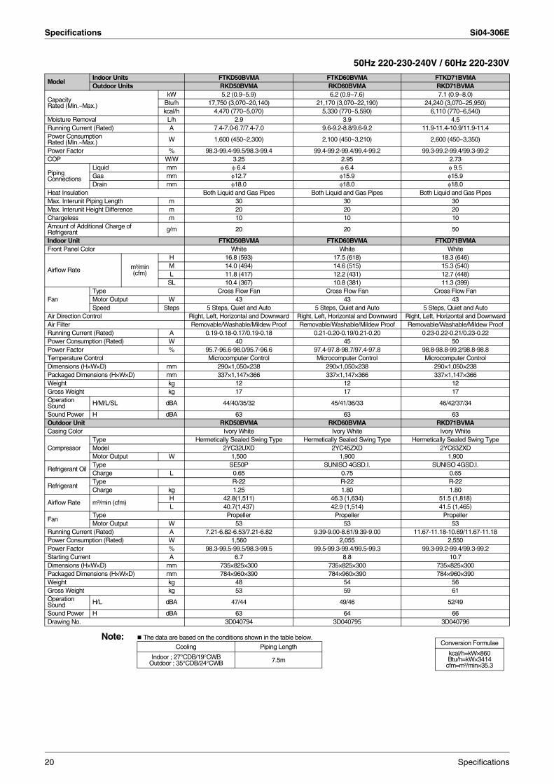
50Hz 220-230-240V / 60Hz 220-230V
Note: The data are based on the conditions shown in the table below.
ModelIndoor Units FTKD50BVMA FTKD60BVMA FTKD71BVMAOutdoor Units RKD50BVMA RKD60BVMA RKD71BVMA
Capacity Rated (Min.~Max.)
kW 5.2 (0.9~5.9) 6.2 (0.9~7.6) 7.1 (0.9~8.0)Btu/h 17,750 (3,070~20,140) 21,170 (3,070~22,190) 24,240 (3,070~25,950)kcal/h 4,470 (770~5,070) 5,330 (770~5,590) 6,110 (770~6,540)
Moisture Removal L/h 2.9 3.9 4.5Running Current (Rated) A 7.4-7.0-6.7/7.4-7.0 9.6-9.2-8.8/9.6-9.2 11.9-11.4-10.9/11.9-11.4Power Consumption Rated (Min.~Max.) W 1,600 (450~2,300) 2,100 (450~3,210) 2,600 (450~3,350)
Power Factor % 98.3-99.4-99.5/98.3-99.4 99.4-99.2-99.4/99.4-99.2 99.3-99.2-99.4/99.3-99.2COP W/W 3.25 2.95 2.73
Piping Connections
Liquid mm φ 6.4 φ 6.4 φ 9.5Gas mm φ12.7 φ15.9 φ15.9Drain mm φ18.0 φ18.0 φ18.0
Heat Insulation Both Liquid and Gas Pipes Both Liquid and Gas Pipes Both Liquid and Gas PipesMax. Interunit Piping Length m 30 30 30Max. Interunit Height Difference m 20 20 20Chargeless m 10 10 10Amount of Additional Charge ofRefrigerant g/m 20 20 50
Indoor Unit FTKD50BVMA FTKD60BVMA FTKD71BVMAFront Panel Color White White White
Airflow Rate m³/min(cfm)
H 16.8 (593) 17.5 (618) 18.3 (646)M 14.0 (494) 14.6 (515) 15.3 (540)L 11.8 (417) 12.2 (431) 12.7 (448)
SL 10.4 (367) 10.8 (381) 11.3 (399)
FanType Cross Flow Fan Cross Flow Fan Cross Flow FanMotor Output W 43 43 43Speed Steps 5 Steps, Quiet and Auto 5 Steps, Quiet and Auto 5 Steps, Quiet and Auto
Air Direction Control Right, Left, Horizontal and Downward Right, Left, Horizontal and Downward Right, Left, Horizontal and DownwardAir Filter Removable/Washable/Mildew Proof Removable/Washable/Mildew Proof Removable/Washable/Mildew ProofRunning Current (Rated) A 0.19-0.18-0.17/0.19-0.18 0.21-0.20-0.19/0.21-0.20 0.23-0.22-0.21/0.23-0.22Power Consumption (Rated) W 40 45 50Power Factor % 95.7-96.6-98.0/95.7-96.6 97.4-97.8-98.7/97.4-97.8 98.8-98.8-99.2/98.8-98.8Temperature Control Microcomputer Control Microcomputer Control Microcomputer ControlDimensions (H×W×D) mm 290×1,050×238 290×1,050×238 290×1,050×238Packaged Dimensions (H×W×D) mm 337×1,147×366 337×1,147×366 337×1,147×366Weight kg 12 12 12Gross Weight kg 17 17 17Operation Sound H/M/L/SL dBA 44/40/35/32 45/41/36/33 46/42/37/34
Sound Power H dBA 63 63 63Outdoor Unit RKD50BVMA RKD60BVMA RKD71BVMACasing Color Ivory White Ivory White Ivory White
CompressorType Hermetically Sealed Swing Type Hermetically Sealed Swing Type Hermetically Sealed Swing TypeModel 2YC32UXD 2YC45ZXD 2YC63ZXDMotor Output W 1,500 1,900 1,900
Refrigerant OilType SE50P SUNISO 4GSD.I. SUNISO 4GSD.I.Charge L 0.65 0.75 0.65
RefrigerantType R-22 R-22 R-22Charge kg 1.25 1.80 1.80
Airflow Rate m³/min (cfm)H 42.8(1,511) 46.3 (1,634) 51.5 (1,818)L 40.7(1,437) 42.9 (1,514) 41.5 (1,465)
FanType Propeller Propeller PropellerMotor Output W 53 53 53
Running Current (Rated) A 7.21-6.82-6.53/7.21-6.82 9.39-9.00-8.61/9.39-9.00 11.67-11.18-10.69/11.67-11.18Power Consumption (Rated) W 1,560 2,055 2,550Power Factor % 98.3-99.5-99.5/98.3-99.5 99.5-99.3-99.4/99.5-99.3 99.3-99.2-99.4/99.3-99.2Starting Current A 6.7 8.8 10.7Dimensions (H×W×D) mm 735×825×300 735×825×300 735×825×300Packaged Dimensions (H×W×D) mm 784×960×390 784×960×390 784×960×390Weight kg 48 54 56Gross Weight kg 53 59 61Operation Sound H/L dBA 47/44 49/46 52/49
Sound Power H dBA 63 64 66Drawing No. 3D040794 3D040795 3D040796
Conversion Formulae
kcal/h=kW×860Btu/h=kW×3414
cfm=m³/min×35.3
Cooling Piping Length
Indoor ; 27°CDB/19°CWB Outdoor ; 35°CDB/24°CWB 7.5m
20 Specifications
Si04-306E Specifications
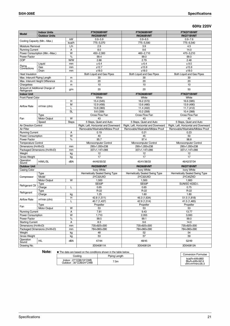
60Hz 220V
Note: The data are based on the conditions shown in the table below.
ModelIndoor Units FTKD50BVMT FTKD60BVMT FTKD71BVMTOutdoor Units RKD50BVMT RKD60BVMT RKD71BVMT
Cooling Capacity (Min.~Max.)kW 0.9~5.9 0.9~6.5 0.9~7.6
kcal/h 775~5,070 775~5,590 775~6,540Moisture Removal L/h 2.9 3.9 4.5Running Current A 8.0 9.6 14.0Power Consumption (Min.~Max.) W 450~2,300 460~2,710 470~3,210Power Factor % 99.4 99.0 99.0COP W/W 2.86 2.79 2.48
Piping Connections
Liquid mm φ 6.4 φ 6.4 φ 9.5Gas mm φ12.7 φ15.9 φ15.9Drain mm φ18.0 φ18.0 φ18.0
Heat Insulation Both Liquid and Gas Pipes Both Liquid and Gas Pipes Both Liquid and Gas PipesMax. Interunit Piping Length m 30 30 30Max. Interunit Height Difference m 20 20 20Chargeless m 10 10 10Amount of Additional Charge ofRefrigerant g/m 20 20 50
Indoor Unit FTKD50BVMT FTKD60BVMT FTKD71BVMTFront Panel Color White White White
Airflow Rate m³/min (cfm)
H 15.4 (545) 16.2 (572) 16.6 (585)M 12.9 (456) 13.6 (480) 13.9 (490)L 10.8 (383) 11.4 (402) 11.7 (412)
SL 9.6 (339) 10.2 (358) 10.4 (368)
FanType Cross Flow Fan Cross Flow Fan Cross Flow FanMotor Output W 43 43 43Speed Steps 5 Steps, Quiet and Auto 5 Steps, Quiet and Auto 5 Steps, Quiet and Auto
Air Direction Control Right, Left, Horizontal and Downward Right, Left, Horizontal and Downward Right, Left, Horizontal and DownwardAir Filter Removable/Washable/Mildew Proof Removable/Washable/Mildew Proof Removable/Washable/Mildew ProofRunning Current A 0.19 0.21 0.23Power Consumption W 40 45 50Power Factor % 95.7 97.4 98.8Temperature Control Microcomputer Control Microcomputer Control Microcomputer ControlDimensions (H×W×D) mm 290×1,050×238 290×1,050×238 290×1,050×238Packaged Dimensions (H×W×D) mm 337×1,147×366 337×1,147×366 337×1,147×366Weight kg 12 12 12Gross Weight kg 17 17 17Operation Sound H/M/L/SL dBA 44/40/35/32 45/41/36/33 46/42/37/34
Outdoor Unit RKD50BVMT RKD60BVMT RKD71BVMTCasing Color Ivory White Ivory White Ivory White
CompressorType Hermetically Sealed Swing Type Hermetically Sealed Swing Type Hermetically Sealed Swing TypeModel 2YC32UXD 2YC32UXD 2YC45ZXDMotor Output W 1,500 1,500 1,900
Refrigerant OilType SE50P SE50P SUNISO 4GSD.I.Charge L 0.65 0.65 0.75
RefrigerantType R-22 R-22 R-22Charge kg 1.25 1.60 1.80
Airflow Rate m³/min (cfm)H 42.8 (1,511) 46.3 (1,634) 51.5 (1,818)L 40.7 (1,437) 42.9 (1,514) 41.5 (1,465)
FanType Propeller Propeller PropellerMotor Output W 53 53 53
Running Current A 7.81 9.43 13.77Power Consumption W 1,710 2,055 3,000Power Factor % 99.5 99.1 99.0Starting Current A 8.3 9.6 14.0Dimensions (H×W×D) mm 735×825×300 735×825×300 735×825×300Packaged Dimensions (H×W×D) mm 784×960×390 784×960×390 784×960×390Weight kg 48 52 54Gross Weight kg 53 57 59Operation Sound H/L dBA 47/44 48/45 52/49
Drawing No. 3D040811A 3D040812A 3D040813A
Conversion Formulae
kcal/h=kW×860Btu/h=kW×3414
cfm=m³/min×35.3
Cooling Piping Length
Indoor ; 27°CDB/19°CWB Outdoor ; 35°CDB/24°CWB 7.5m
Specifications 21
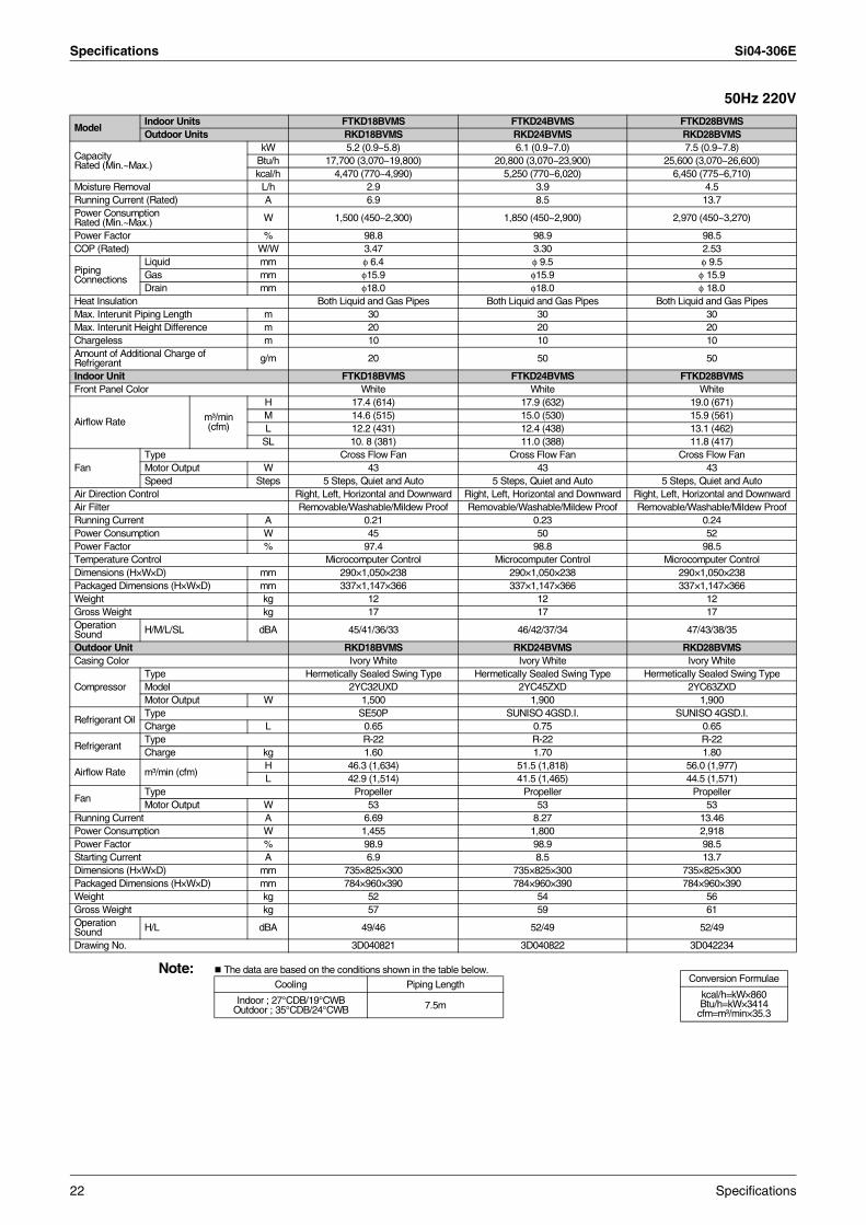
Specifications Si04-306E
50Hz 220V
Note: The data are based on the conditions shown in the table below.
ModelIndoor Units FTKD18BVMS FTKD24BVMS FTKD28BVMSOutdoor Units RKD18BVMS RKD24BVMS RKD28BVMS
Capacity Rated (Min.~Max.)
kW 5.2 (0.9~5.8) 6.1 (0.9~7.0) 7.5 (0.9~7.8)Btu/h 17,700 (3,070~19,800) 20,800 (3,070~23,900) 25,600 (3,070~26,600)kcal/h 4,470 (770~4,990) 5,250 (770~6,020) 6,450 (775~6,710)
Moisture Removal L/h 2.9 3.9 4.5Running Current (Rated) A 6.9 8.5 13.7Power Consumption Rated (Min.~Max.) W 1,500 (450~2,300) 1,850 (450~2,900) 2,970 (450~3,270)
Power Factor % 98.8 98.9 98.5COP (Rated) W/W 3.47 3.30 2.53
Piping Connections
Liquid mm φ 6.4 φ 9.5 φ 9.5Gas mm φ15.9 φ15.9 φ 15.9Drain mm φ18.0 φ18.0 φ 18.0
Heat Insulation Both Liquid and Gas Pipes Both Liquid and Gas Pipes Both Liquid and Gas PipesMax. Interunit Piping Length m 30 30 30Max. Interunit Height Difference m 20 20 20Chargeless m 10 10 10Amount of Additional Charge ofRefrigerant g/m 20 50 50
Indoor Unit FTKD18BVMS FTKD24BVMS FTKD28BVMSFront Panel Color White White White
Airflow Rate m³/min(cfm)
H 17.4 (614) 17.9 (632) 19.0 (671)M 14.6 (515) 15.0 (530) 15.9 (561)L 12.2 (431) 12.4 (438) 13.1 (462)
SL 10. 8 (381) 11.0 (388) 11.8 (417)
FanType Cross Flow Fan Cross Flow Fan Cross Flow FanMotor Output W 43 43 43Speed Steps 5 Steps, Quiet and Auto 5 Steps, Quiet and Auto 5 Steps, Quiet and Auto
Air Direction Control Right, Left, Horizontal and Downward Right, Left, Horizontal and Downward Right, Left, Horizontal and DownwardAir Filter Removable/Washable/Mildew Proof Removable/Washable/Mildew Proof Removable/Washable/Mildew ProofRunning Current A 0.21 0.23 0.24Power Consumption W 45 50 52Power Factor % 97.4 98.8 98.5Temperature Control Microcomputer Control Microcomputer Control Microcomputer ControlDimensions (H×W×D) mm 290×1,050×238 290×1,050×238 290×1,050×238Packaged Dimensions (H×W×D) mm 337×1,147×366 337×1,147×366 337×1,147×366Weight kg 12 12 12Gross Weight kg 17 17 17Operation Sound H/M/L/SL dBA 45/41/36/33 46/42/37/34 47/43/38/35
Outdoor Unit RKD18BVMS RKD24BVMS RKD28BVMSCasing Color Ivory White Ivory White Ivory White
CompressorType Hermetically Sealed Swing Type Hermetically Sealed Swing Type Hermetically Sealed Swing TypeModel 2YC32UXD 2YC45ZXD 2YC63ZXDMotor Output W 1,500 1,900 1,900
Refrigerant OilType SE50P SUNISO 4GSD.I. SUNISO 4GSD.I.Charge L 0.65 0.75 0.65
RefrigerantType R-22 R-22 R-22Charge kg 1.60 1.70 1.80
Airflow Rate m³/min (cfm)H 46.3 (1,634) 51.5 (1,818) 56.0 (1,977)L 42.9 (1,514) 41.5 (1,465) 44.5 (1,571)
FanType Propeller Propeller PropellerMotor Output W 53 53 53
Running Current A 6.69 8.27 13.46Power Consumption W 1,455 1,800 2,918Power Factor % 98.9 98.9 98.5Starting Current A 6.9 8.5 13.7Dimensions (H×W×D) mm 735×825×300 735×825×300 735×825×300Packaged Dimensions (H×W×D) mm 784×960×390 784×960×390 784×960×390Weight kg 52 54 56Gross Weight kg 57 59 61Operation Sound H/L dBA 49/46 52/49 52/49
Drawing No. 3D040821 3D040822 3D042234
Conversion Formulae
kcal/h=kW×860Btu/h=kW×3414
cfm=m³/min×35.3
Cooling Piping Length
Indoor ; 27°CDB/19°CWB Outdoor ; 35°CDB/24°CWB 7.5m
22 Specifications
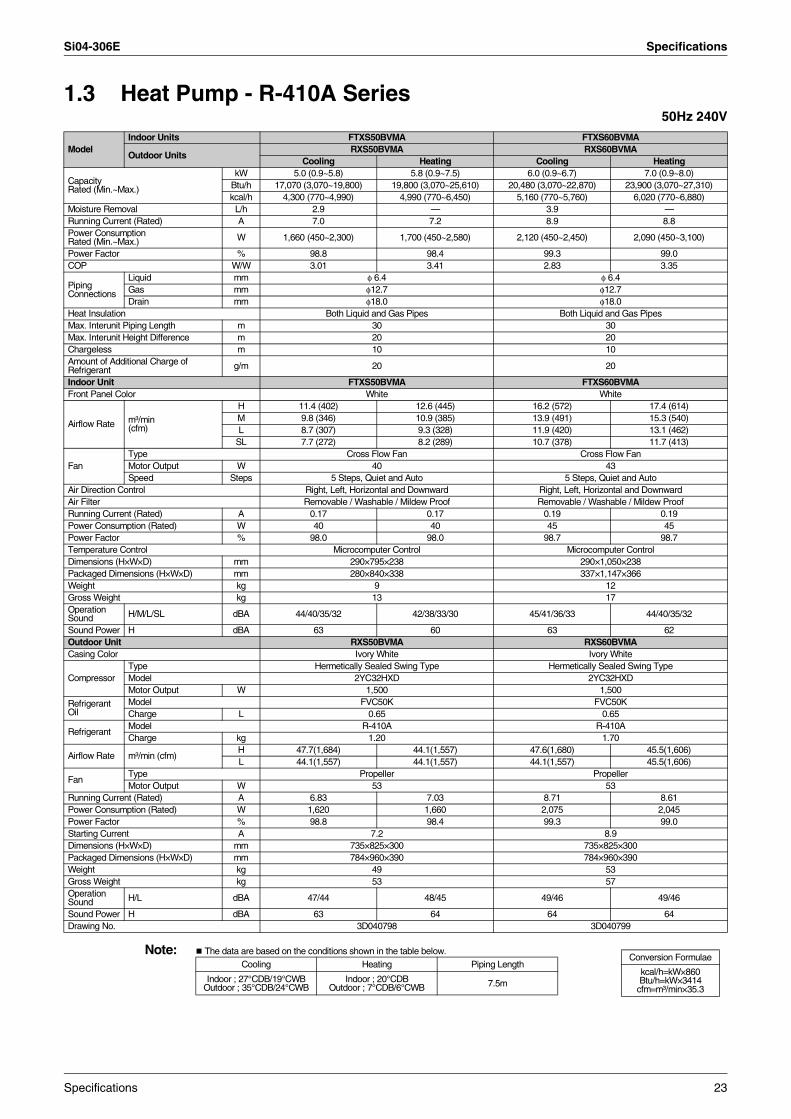
Si04-306E Specifications
1.3 Heat Pump - R-410A Series50Hz 240V
Note: The data are based on the conditions shown in the table below.
ModelIndoor Units FTXS50BVMA FTXS60BVMA
Outdoor UnitsRXS50BVMA RXS60BVMA
Cooling Heating Cooling Heating
Capacity Rated (Min.~Max.)
kW 5.0 (0.9~5.8) 5.8 (0.9~7.5) 6.0 (0.9~6.7) 7.0 (0.9~8.0)Btu/h 17,070 (3,070~19,800) 19,800 (3,070~25,610) 20,480 (3,070~22,870) 23,900 (3,070~27,310)kcal/h 4,300 (770~4,990) 4,990 (770~6,450) 5,160 (770~5,760) 6,020 (770~6,880)
Moisture Removal L/h 2.9 — 3.9 —Running Current (Rated) A 7.0 7.2 8.9 8.8Power Consumption Rated (Min.~Max.) W 1,660 (450~2,300) 1,700 (450~2,580) 2,120 (450~2,450) 2,090 (450~3,100)
Power Factor % 98.8 98.4 99.3 99.0COP W/W 3.01 3.41 2.83 3.35
Piping Connections
Liquid mm φ 6.4 φ 6.4Gas mm φ12.7 φ12.7Drain mm φ18.0 φ18.0
Heat Insulation Both Liquid and Gas Pipes Both Liquid and Gas PipesMax. Interunit Piping Length m 30 30Max. Interunit Height Difference m 20 20Chargeless m 10 10Amount of Additional Charge ofRefrigerant g/m 20 20
Indoor Unit FTXS50BVMA FTXS60BVMAFront Panel Color White White
Airflow Rate m³/min (cfm)
H 11.4 (402) 12.6 (445) 16.2 (572) 17.4 (614)M 9.8 (346) 10.9 (385) 13.9 (491) 15.3 (540)L 8.7 (307) 9.3 (328) 11.9 (420) 13.1 (462)
SL 7.7 (272) 8.2 (289) 10.7 (378) 11.7 (413)
FanType Cross Flow Fan Cross Flow FanMotor Output W 40 43Speed Steps 5 Steps, Quiet and Auto 5 Steps, Quiet and Auto
Air Direction Control Right, Left, Horizontal and Downward Right, Left, Horizontal and DownwardAir Filter Removable / Washable / Mildew Proof Removable / Washable / Mildew ProofRunning Current (Rated) A 0.17 0.17 0.19 0.19Power Consumption (Rated) W 40 40 45 45Power Factor % 98.0 98.0 98.7 98.7Temperature Control Microcomputer Control Microcomputer ControlDimensions (H×W×D) mm 290×795×238 290×1,050×238Packaged Dimensions (H×W×D) mm 280×840×338 337×1,147×366Weight kg 9 12Gross Weight kg 13 17Operation Sound H/M/L/SL dBA 44/40/35/32 42/38/33/30 45/41/36/33 44/40/35/32
Sound Power H dBA 63 60 63 62Outdoor Unit RXS50BVMA RXS60BVMACasing Color Ivory White Ivory White
CompressorType Hermetically Sealed Swing Type Hermetically Sealed Swing TypeModel 2YC32HXD 2YC32HXDMotor Output W 1,500 1,500
Refrigerant Oil
Model FVC50K FVC50KCharge L 0.65 0.65
RefrigerantModel R-410A R-410ACharge kg 1.20 1.70
Airflow Rate m³/min (cfm)H 47.7(1,684) 44.1(1,557) 47.6(1,680) 45.5(1,606)L 44.1(1,557) 44.1(1,557) 44.1(1,557) 45.5(1,606)
FanType Propeller PropellerMotor Output W 53 53
Running Current (Rated) A 6.83 7.03 8.71 8.61Power Consumption (Rated) W 1,620 1,660 2,075 2,045Power Factor % 98.8 98.4 99.3 99.0Starting Current A 7.2 8.9Dimensions (H×W×D) mm 735×825×300 735×825×300Packaged Dimensions (H×W×D) mm 784×960×390 784×960×390Weight kg 49 53Gross Weight kg 53 57Operation Sound H/L dBA 47/44 48/45 49/46 49/46
Sound Power H dBA 63 64 64 64Drawing No. 3D040798 3D040799
Conversion Formulae
kcal/h=kW×860Btu/h=kW×3414
cfm=m³/min×35.3
Cooling Heating Piping Length
Indoor ; 27°CDB/19°CWB Outdoor ; 35°CDB/24°CWB
Indoor ; 20°CDBOutdoor ; 7°CDB/6°CWB 7.5m
Specifications 23
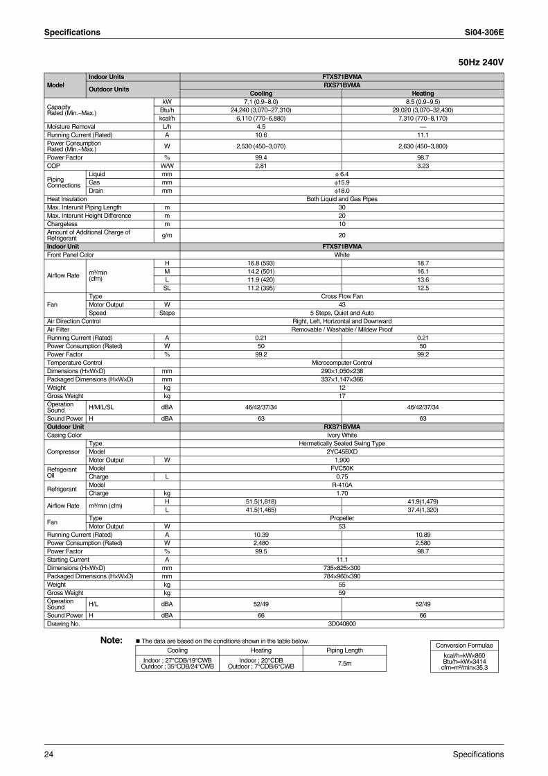
Specifications Si04-306E
50Hz 240V
Note: The data are based on the conditions shown in the table below.
ModelIndoor Units FTXS71BVMA
Outdoor UnitsRXS71BVMA
Cooling Heating
Capacity Rated (Min.~Max.)
kW 7.1 (0.9~8.0) 8.5 (0.9~9.5)Btu/h 24,240 (3,070~27,310) 29,020 (3,070~32,430)kcal/h 6,110 (770~6,880) 7,310 (770~8,170)
Moisture Removal L/h 4.5 —Running Current (Rated) A 10.6 11.1Power Consumption Rated (Min.~Max.) W 2,530 (450~3,070) 2,630 (450~3,800)
Power Factor % 99.4 98.7COP W/W 2.81 3.23
Piping Connections
Liquid mm φ 6.4Gas mm φ15.9Drain mm φ18.0
Heat Insulation Both Liquid and Gas PipesMax. Interunit Piping Length m 30Max. Interunit Height Difference m 20Chargeless m 10Amount of Additional Charge ofRefrigerant g/m 20
Indoor Unit FTXS71BVMAFront Panel Color White
Airflow Rate m³/min (cfm)
H 16.8 (593) 18.7M 14.2 (501) 16.1L 11.9 (420) 13.6
SL 11.2 (395) 12.5
FanType Cross Flow FanMotor Output W 43Speed Steps 5 Steps, Quiet and Auto
Air Direction Control Right, Left, Horizontal and DownwardAir Filter Removable / Washable / Mildew ProofRunning Current (Rated) A 0.21 0.21Power Consumption (Rated) W 50 50Power Factor % 99.2 99.2Temperature Control Microcomputer ControlDimensions (H×W×D) mm 290×1,050×238Packaged Dimensions (H×W×D) mm 337×1,147×366Weight kg 12Gross Weight kg 17Operation Sound H/M/L/SL dBA 46/42/37/34 46/42/37/34
Sound Power H dBA 63 63Outdoor Unit RXS71BVMACasing Color Ivory White
CompressorType Hermetically Sealed Swing TypeModel 2YC45BXDMotor Output W 1,900
Refrigerant Oil
Model FVC50KCharge L 0.75
RefrigerantModel R-410ACharge kg 1.70
Airflow Rate m³/min (cfm)H 51.5(1,818) 41.9(1,479)L 41.5(1,465) 37.4(1,320)
FanType PropellerMotor Output W 53
Running Current (Rated) A 10.39 10.89Power Consumption (Rated) W 2,480 2,580Power Factor % 99.5 98.7Starting Current A 11.1Dimensions (H×W×D) mm 735×825×300Packaged Dimensions (H×W×D) mm 784×960×390Weight kg 55Gross Weight kg 59Operation Sound H/L dBA 52/49 52/49
Sound Power H dBA 66 66Drawing No. 3D040800
Conversion Formulae
kcal/h=kW×860Btu/h=kW×3414
cfm=m³/min×35.3
Cooling Heating Piping Length
Indoor ; 27°CDB/19°CWB Outdoor ; 35°CDB/24°CWB
Indoor ; 20°CDBOutdoor ; 7°CDB/6°CWB 7.5m
24 Specifications
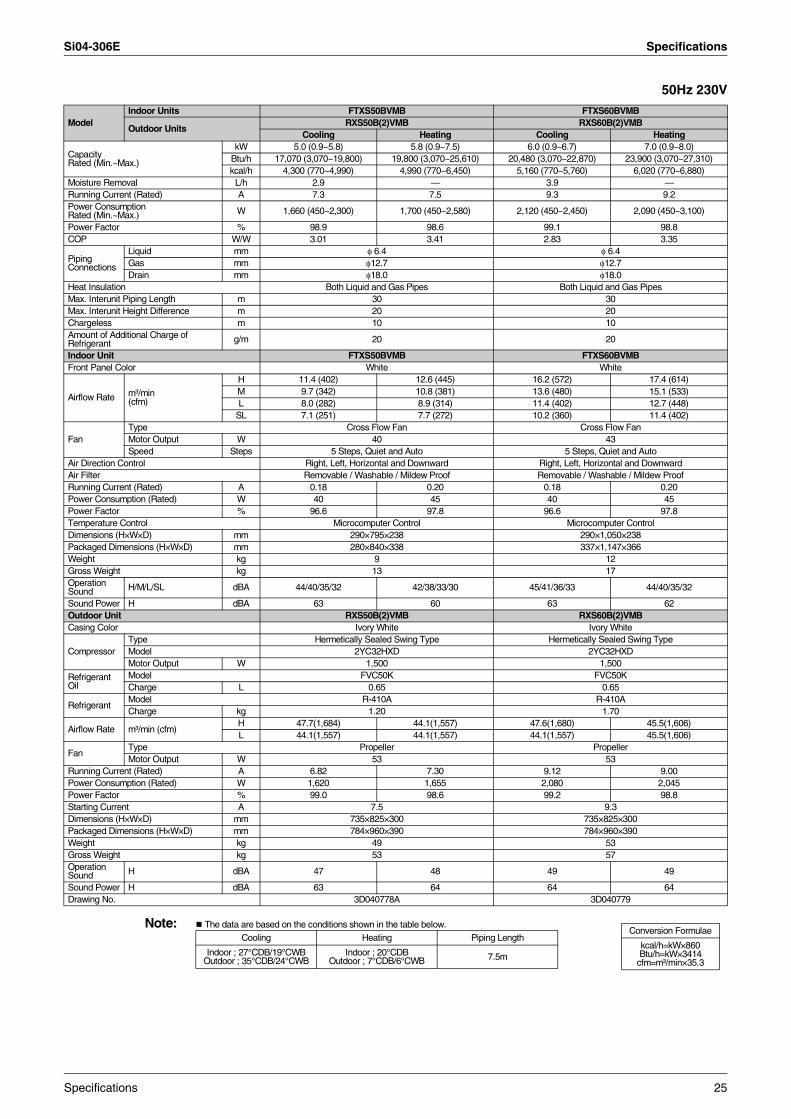
Si04-306E Specifications
50Hz 230V
Note: The data are based on the conditions shown in the table below.
ModelIndoor Units FTXS50BVMB FTXS60BVMB
Outdoor UnitsRXS50B(2)VMB RXS60B(2)VMB
Cooling Heating Cooling Heating
Capacity Rated (Min.~Max.)
kW 5.0 (0.9~5.8) 5.8 (0.9~7.5) 6.0 (0.9~6.7) 7.0 (0.9~8.0)Btu/h 17,070 (3,070~19,800) 19,800 (3,070~25,610) 20,480 (3,070~22,870) 23,900 (3,070~27,310)kcal/h 4,300 (770~4,990) 4,990 (770~6,450) 5,160 (770~5,760) 6,020 (770~6,880)
Moisture Removal L/h 2.9 — 3.9 —Running Current (Rated) A 7.3 7.5 9.3 9.2Power Consumption Rated (Min.~Max.) W 1,660 (450~2,300) 1,700 (450~2,580) 2,120 (450~2,450) 2,090 (450~3,100)
Power Factor % 98.9 98.6 99.1 98.8COP W/W 3.01 3.41 2.83 3.35
Piping Connections
Liquid mm φ 6.4 φ 6.4Gas mm φ12.7 φ12.7Drain mm φ18.0 φ18.0
Heat Insulation Both Liquid and Gas Pipes Both Liquid and Gas PipesMax. Interunit Piping Length m 30 30Max. Interunit Height Difference m 20 20Chargeless m 10 10Amount of Additional Charge ofRefrigerant g/m 20 20
Indoor Unit FTXS50BVMB FTXS60BVMBFront Panel Color White White
Airflow Rate m³/min (cfm)
H 11.4 (402) 12.6 (445) 16.2 (572) 17.4 (614)M 9.7 (342) 10.8 (381) 13.6 (480) 15.1 (533)L 8.0 (282) 8.9 (314) 11.4 (402) 12.7 (448)
SL 7.1 (251) 7.7 (272) 10.2 (360) 11.4 (402)
FanType Cross Flow Fan Cross Flow FanMotor Output W 40 43Speed Steps 5 Steps, Quiet and Auto 5 Steps, Quiet and Auto
Air Direction Control Right, Left, Horizontal and Downward Right, Left, Horizontal and DownwardAir Filter Removable / Washable / Mildew Proof Removable / Washable / Mildew ProofRunning Current (Rated) A 0.18 0.20 0.18 0.20Power Consumption (Rated) W 40 45 40 45Power Factor % 96.6 97.8 96.6 97.8Temperature Control Microcomputer Control Microcomputer ControlDimensions (H×W×D) mm 290×795×238 290×1,050×238Packaged Dimensions (H×W×D) mm 280×840×338 337×1,147×366Weight kg 9 12Gross Weight kg 13 17Operation Sound H/M/L/SL dBA 44/40/35/32 42/38/33/30 45/41/36/33 44/40/35/32
Sound Power H dBA 63 60 63 62Outdoor Unit RXS50B(2)VMB RXS60B(2)VMBCasing Color Ivory White Ivory White
CompressorType Hermetically Sealed Swing Type Hermetically Sealed Swing TypeModel 2YC32HXD 2YC32HXDMotor Output W 1,500 1,500
Refrigerant Oil
Model FVC50K FVC50KCharge L 0.65 0.65
RefrigerantModel R-410A R-410ACharge kg 1.20 1.70
Airflow Rate m³/min (cfm)H 47.7(1,684) 44.1(1,557) 47.6(1,680) 45.5(1,606)L 44.1(1,557) 44.1(1,557) 44.1(1,557) 45.5(1,606)
FanType Propeller PropellerMotor Output W 53 53
Running Current (Rated) A 6.82 7.30 9.12 9.00Power Consumption (Rated) W 1,620 1,655 2,080 2,045Power Factor % 99.0 98.6 99.2 98.8Starting Current A 7.5 9.3Dimensions (H×W×D) mm 735×825×300 735×825×300Packaged Dimensions (H×W×D) mm 784×960×390 784×960×390Weight kg 49 53Gross Weight kg 53 57Operation Sound H dBA 47 48 49 49
Sound Power H dBA 63 64 64 64Drawing No. 3D040778A 3D040779
Conversion Formulae
kcal/h=kW×860Btu/h=kW×3414
cfm=m³/min×35.3
Cooling Heating Piping Length
Indoor ; 27°CDB/19°CWB Outdoor ; 35°CDB/24°CWB
Indoor ; 20°CDBOutdoor ; 7°CDB/6°CWB 7.5m
Specifications 25
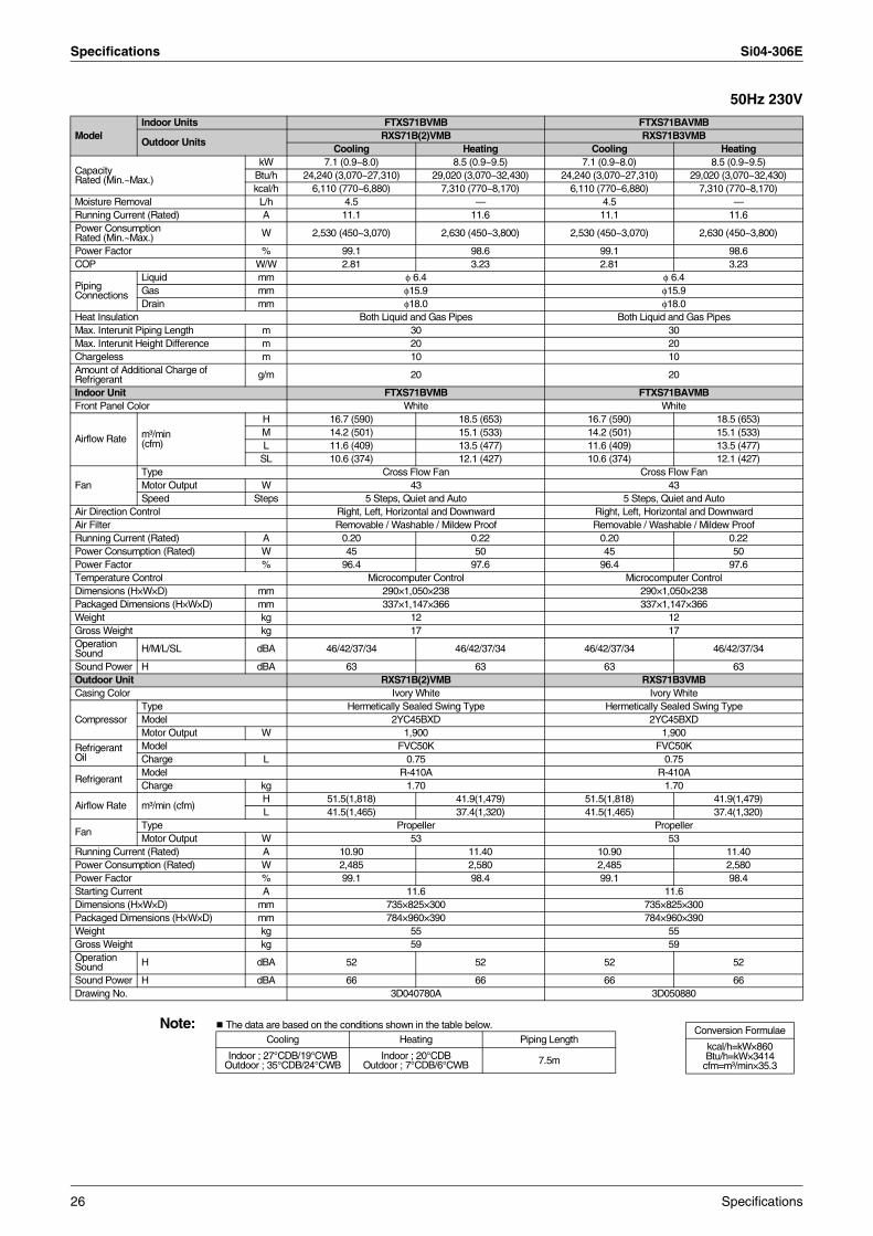
Specifications Si04-306E
50Hz 230V
Note: The data are based on the conditions shown in the table below.
ModelIndoor Units FTXS71BVMB FTXS71BAVMB
Outdoor UnitsRXS71B(2)VMB RXS71B3VMB
Cooling Heating Cooling Heating
Capacity Rated (Min.~Max.)
kW 7.1 (0.9~8.0) 8.5 (0.9~9.5) 7.1 (0.9~8.0) 8.5 (0.9~9.5)Btu/h 24,240 (3,070~27,310) 29,020 (3,070~32,430) 24,240 (3,070~27,310) 29,020 (3,070~32,430)kcal/h 6,110 (770~6,880) 7,310 (770~8,170) 6,110 (770~6,880) 7,310 (770~8,170)
Moisture Removal L/h 4.5 — 4.5 —Running Current (Rated) A 11.1 11.6 11.1 11.6Power Consumption Rated (Min.~Max.) W 2,530 (450~3,070) 2,630 (450~3,800) 2,530 (450~3,070) 2,630 (450~3,800)
Power Factor % 99.1 98.6 99.1 98.6COP W/W 2.81 3.23 2.81 3.23
Piping Connections
Liquid mm φ 6.4 φ 6.4Gas mm φ15.9 φ15.9Drain mm φ18.0 φ18.0
Heat Insulation Both Liquid and Gas Pipes Both Liquid and Gas PipesMax. Interunit Piping Length m 30 30Max. Interunit Height Difference m 20 20Chargeless m 10 10Amount of Additional Charge ofRefrigerant g/m 20 20
Indoor Unit FTXS71BVMB FTXS71BAVMBFront Panel Color White White
Airflow Rate m³/min (cfm)
H 16.7 (590) 18.5 (653) 16.7 (590) 18.5 (653)M 14.2 (501) 15.1 (533) 14.2 (501) 15.1 (533)L 11.6 (409) 13.5 (477) 11.6 (409) 13.5 (477)
SL 10.6 (374) 12.1 (427) 10.6 (374) 12.1 (427)
FanType Cross Flow Fan Cross Flow FanMotor Output W 43 43Speed Steps 5 Steps, Quiet and Auto 5 Steps, Quiet and Auto
Air Direction Control Right, Left, Horizontal and Downward Right, Left, Horizontal and DownwardAir Filter Removable / Washable / Mildew Proof Removable / Washable / Mildew ProofRunning Current (Rated) A 0.20 0.22 0.20 0.22Power Consumption (Rated) W 45 50 45 50Power Factor % 96.4 97.6 96.4 97.6Temperature Control Microcomputer Control Microcomputer ControlDimensions (H×W×D) mm 290×1,050×238 290×1,050×238Packaged Dimensions (H×W×D) mm 337×1,147×366 337×1,147×366Weight kg 12 12Gross Weight kg 17 17Operation Sound H/M/L/SL dBA 46/42/37/34 46/42/37/34 46/42/37/34 46/42/37/34
Sound Power H dBA 63 63 63 63Outdoor Unit RXS71B(2)VMB RXS71B3VMBCasing Color Ivory White Ivory White
CompressorType Hermetically Sealed Swing Type Hermetically Sealed Swing TypeModel 2YC45BXD 2YC45BXDMotor Output W 1,900 1,900
Refrigerant Oil
Model FVC50K FVC50KCharge L 0.75 0.75
RefrigerantModel R-410A R-410ACharge kg 1.70 1.70
Airflow Rate m³/min (cfm)H 51.5(1,818) 41.9(1,479) 51.5(1,818) 41.9(1,479)L 41.5(1,465) 37.4(1,320) 41.5(1,465) 37.4(1,320)
FanType Propeller PropellerMotor Output W 53 53
Running Current (Rated) A 10.90 11.40 10.90 11.40Power Consumption (Rated) W 2,485 2,580 2,485 2,580Power Factor % 99.1 98.4 99.1 98.4Starting Current A 11.6 11.6Dimensions (H×W×D) mm 735×825×300 735×825×300Packaged Dimensions (H×W×D) mm 784×960×390 784×960×390Weight kg 55 55Gross Weight kg 59 59Operation Sound H dBA 52 52 52 52
Sound Power H dBA 66 66 66 66Drawing No. 3D040780A 3D050880
Conversion Formulae
kcal/h=kW×860Btu/h=kW×3414
cfm=m³/min×35.3
Cooling Heating Piping Length
Indoor ; 27°CDB/19°CWB Outdoor ; 35°CDB/24°CWB
Indoor ; 20°CDBOutdoor ; 7°CDB/6°CWB 7.5m
26 Specifications
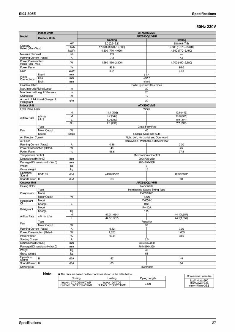
Si04-306E Specifications
50Hz 230V
Note: The data are based on the conditions shown in the table below.
ModelIndoor Units ATXS50CVMB
Outdoor UnitsARXS50C(2)VMB
Cooling Heating
Capacity Rated (Min.~Max.)
kW 5.0 (0.9~5.8) 5.8 (0.9~7.5)Btu/h 17,070 (3,070~19,800) 19,800 (3,070~25,610)kcal/h 4,300 (770~4,990) 4,990 (770~6,450)
Moisture Removal L/h 2.9 —Running Current (Rated) A 7.3 7.5Power Consumption Rated (Min.~Max.) W 1,660 (450~2,300) 1,700 (450~2,580)
Power Factor % 98.9 98.6COP W/W 3.01 3.41
Piping Connections
Liquid mm φ 6.4Gas mm φ12.7Drain mm φ18.0
Heat Insulation Both Liquid and Gas PipesMax. Interunit Piping Length m 30Max. Interunit Height Difference m 20Chargeless m 10Amount of Additional Charge ofRefrigerant g/m 20
Indoor Unit ATXS50CVMBFront Panel Color White
Airflow Rate m³/min (cfm)
H 11.4 (402) 12.6 (445)M 9.7 (342) 10.8 (381)L 8.0 (282) 8.9 (314)
SL 7.1 (251) 7.7 (272)
FanType Cross Flow FanMotor Output W 40Speed Steps 5 Steps, Quiet and Auto
Air Direction Control Right, Left, Horizontal and DownwardAir Filter Removable / Washable / Mildew ProofRunning Current (Rated) A 0.18 0.20Power Consumption (Rated) W 40 45Power Factor % 96.6 97.8Temperature Control Microcomputer ControlDimensions (H×W×D) mm 290×795×230Packaged Dimensions (H×W×D) mm 280×840×338Weight kg 9Gross Weight kg 13Operation Sound H/M/L/SL dBA 44/40/35/32 42/38/33/30
Sound Power H dBA 63 60Outdoor Unit ARXS50C(2)VMBCasing Color Ivory White
CompressorType Hermetically Sealed Swing TypeModel 2YC32HXDMotor Output W 1,500
Refrigerant Oil
Model FVC50KCharge L 0.65
RefrigerantModel R-410ACharge kg 1.20
Airflow Rate m³/min (cfm)H 47.7(1,684) 44.1(1,557)L 44.1(1,557) 44.1(1,557)
FanType PropellerMotor Output W 53
Running Current (Rated) A 6.82 7.30Power Consumption (Rated) W 1,620 1,655Power Factor % 99.0 98.6Starting Current A 7.5Dimensions (H×W×D) mm 735×825×300Packaged Dimensions (H×W×D) mm 784×960×390Weight kg 49Gross Weight kg 53Operation Sound H dBA 47 48
Sound Power H dBA 63 64Drawing No. 3D044869
Conversion Formulae
kcal/h=kW×860Btu/h=kW×3414
cfm=m³/min×35.3
Cooling Heating Piping Length
Indoor ; 27°CDB/19°CWB Outdoor ; 35°CDB/24°CWB
Indoor ; 20°CDBOutdoor ; 7°CDB/6°CWB 7.5m
Specifications 27

Specifications Si04-306E
50Hz 230V
Note: The data are based on the conditions shown in the table below.
ModelIndoor Units ATXS50DVMB
Outdoor UnitsARXS50C(2)VMB
Cooling Heating
Capacity Rated (Min.~Max.)
kW 5.0 (0.9~5.8) 5.8 (0.9~7.5)Btu/h 17,070 (3,070~19,800) 19,800 (3,070~25,610)kcal/h 4,300 (770~4,990) 4,990 (770~6,450)
Moisture Removal L/h 2.9 —Running Current (Rated) A 7.3 7.5Power Consumption Rated (Min.~Max.) W 1,660 (450~2,300) 1,700 (450~2,580)
Power Factor % 98.9 98.6COP W/W 3.01 3.41
Piping Connections
Liquid mm φ 6.4Gas mm φ12.7Drain mm φ18.0
Heat Insulation Both Liquid and Gas PipesMax. Interunit Piping Length m 30Max. Interunit Height Difference m 20Chargeless m 10Amount of Additional Charge ofRefrigerant g/m 20
Indoor Unit ATXS50DVMBFront Panel Color White
Airflow Rate m³/min (cfm)
H 11.4 (402) 12.6 (445)M 9.7 (342) 10.8 (381)L 8.0 (282) 8.9 (314)
SL 7.1 (251) 7.7 (272)
FanType Cross Flow FanMotor Output W 40Speed Steps 5 Steps, Quiet and Auto
Air Direction Control Right, Left, Horizontal and DownwardAir Filter Removable / Washable / Mildew ProofRunning Current (Rated) A 0.18 0.20Power Consumption (Rated) W 40 45Power Factor % 96.6 97.8Temperature Control Microcomputer ControlDimensions (H×W×D) mm 290×795×238Packaged Dimensions (H×W×D) mm 280×840×338Weight kg 9Gross Weight kg 13Operation Sound H/M/L/SL dBA 44/40/35/32 42/38/33/30
Sound Power H dBA 63 60Outdoor Unit ARXS50C(2)VMBCasing Color Ivory White
CompressorType Hermetically Sealed Swing TypeModel 2YC32HXDMotor Output W 1,500
Refrigerant Oil
Model FVC50KCharge L 0.65
RefrigerantModel R-410ACharge kg 1.20
Airflow Rate (H/L)
m³/min 47.7/44.1 44.1/44.1cfm 1,684/1,557 1,557/1,557
FanType PropellerMotor Output W 53
Running Current (Rated) A 6.82 7.30Power Consumption (Rated) W 1,620 1,655Power Factor % 99.0 98.6Starting Current A 7.5Dimensions (H×W×D) mm 735×825×300Packaged Dimensions (H×W×D) mm 784×960×390Weight kg 49Gross Weight kg 53Operation Sound H/L dBA 47/— 48/—
Sound Power H dBA 63 64Drawing No. 3D047938
Conversion Formulae
kcal/h=kW×860Btu/h=kW×3414
cfm=m³/min×35.3
Cooling Heating Piping Length
Indoor ; 27°CDB/19°CWB Outdoor ; 35°CDB/24°CWB
Indoor ; 20°CDBOutdoor ; 7°CDB/6°CWB 7.5m
28 Specifications
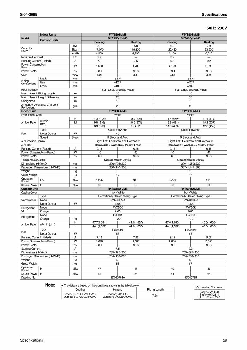
Si04-306E Specifications
50Hz 230V
Note: The data are based on the conditions shown in the table below.
ModelIndoor Units FTYS50BVMB FTYS60BVMB
Outdoor UnitsRYS50B(2)VMB RYS60B(2)VMB
Cooling Heating Cooling Heating
Capacity Rated
kW 5.0 5.8 6.0 7.0Btu/h 17,070 19,800 20,480 23,900kcal/h 4,300 4,990 5,160 6,020
Moisture Removal L/h 2.9 — 3.9 —Running Current (Rated) A 7.3 7.5 9.3 9.2Power Consumption Rated W 1,660 1,700 2,120 2,090
Power Factor % 98.9 98.6 99.1 98.8COP W/W 3.01 3.41 2.83 3.35
Piping Connections
Liquid mm φ 6.4 φ 6.4Gas mm φ12.7 φ12.7Drain mm φ18.0 φ18.0
Heat Insulation Both Liquid and Gas Pipes Both Liquid and Gas PipesMax. Interunit Piping Length m 30 30Max. Interunit Height Difference m 20 20Chargeless m 10 10Amount of Additional Charge ofRefrigerant g/m 20 20
Indoor Unit FTYS50BVMB FTYS60BVMBFront Panel Color White White
Airflow Rate m³/min (cfm)
H 11.5 (406) 12.2 (431) 16.4 (579) 17.5 (618)M 9.8 (346) 10.5 (371) 13.9 (491) 15.2 (537)L 8.3 (293) 8.8 (311) 11.6 (409) 12.8 (452)
FanType Cross Flow Fan Cross Flow FanMotor Output W 40 43Speed Steps 5 Steps and Auto 5 Steps and Auto
Air Direction Control Right, Left, Horizontal and Downward Right, Left, Horizontal and DownwardAir Filter Removable / Washable / Mildew Proof Removable / Washable / Mildew ProofRunning Current (Rated) A 0.18 0.18 0.18 0.18Power Consumption (Rated) W 40 40 40 40Power Factor % 96.6 96.6 96.6 96.6Temperature Control Microcomputer Control Microcomputer ControlDimensions (H×W×D) mm 290×795×230 290×1,050×230Packaged Dimensions (H×W×D) mm 280×840×338 337×1,147×366Weight kg 9 12Gross Weight kg 13 17Operation Sound H/L dBA 44/35 42/— 45/36 44/—
Sound Power H dBA 63 60 63 62Outdoor Unit RYS50B(2)VMB RYS60B(2)VMBCasing Color Ivory White Ivory White
CompressorType Hermetically Sealed Swing Type Hermetically Sealed Swing TypeModel 2YC32HXD 2YC32HXDMotor Output W 1,500 1,500
Refrigerant Oil
Model FVC50K FVC50KCharge L 0.65 0.65
RefrigerantModel R-410A R-410ACharge kg 1.20 1.70
Airflow Rate m³/min (cfm)H 47.7(1,684) 44.1(1,557) 47.6(1,680) 45.5(1,606)L 44.1(1,557) 44.1(1,557) 44.1(1,557) 45.5(1,606)
FanType Propeller PropellerMotor Output W 53 53
Running Current (Rated) A 7.12 7.32 9.12 9.02Power Consumption (Rated) W 1,620 1,660 2,080 2,050Power Factor % 98.9 98.6 99.2 98.8Starting Current A 7.5 9.3Dimensions (H×W×D) mm 735×825×300 735×825×300Packaged Dimensions (H×W×D) mm 784×960×390 784×960×390Weight kg 49 53Gross Weight kg 53 57Operation Sound H dBA 47 48 49 49
Sound Power H dBA 63 64 64 64Drawing No. 3D040784A 3D040785
Conversion Formulae
kcal/h=kW×860Btu/h=kW×3414
cfm=m³/min×35.3
Cooling Heating Piping Length
Indoor ; 27°CDB/19°CWB Outdoor ; 35°CDB/24°CWB
Indoor ; 20°CDBOutdoor ; 7°CDB/6°CWB 7.5m
Specifications 29
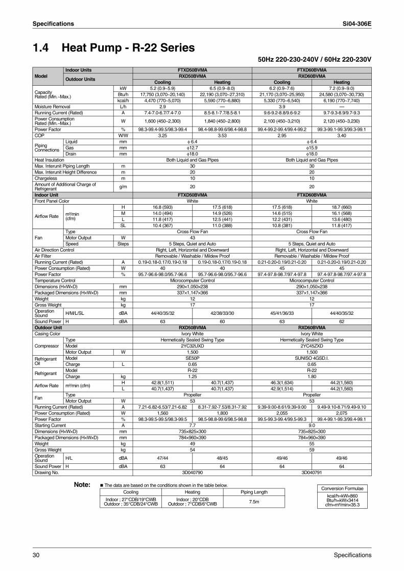
Specifications Si04-306E
1.4 Heat Pump - R-22 Series50Hz 220-230-240V / 60Hz 220-230V
Note: The data are based on the conditions shown in the table below.
ModelIndoor Units FTXD50BVMA FTXD60BVMA
Outdoor UnitsRXD50BVMA RXD60BVMA
Cooling Heating Cooling Heating
Capacity Rated (Min.~Max.)
kW 5.2 (0.9~5.9) 6.5 (0.9~8.0) 6.2 (0.9~7.6) 7.2 (0.9~9.0)Btu/h 17,750 (3,070~20,140) 22,190 (3,070~27,310) 21,170 (3,070~25,950) 24,580 (3,070~30,730)kcal/h 4,470 (770~5,070) 5,590 (770~6,880) 5,330 (770~6,540) 6,190 (770~7,740)
Moisture Removal L/h 2.9 — 3.9 —Running Current (Rated) A 7.4-7.0-6.7/7.4-7.0 8.5-8.1-7.7/8.5-8.1 9.6-9.2-8.8/9.6-9.2 9.7-9.3-8.9/9.7-9.3Power Consumption Rated (Min.~Max.) W 1,600 (450~2,300) 1,840 (450~2,800) 2,100 (450~3,210) 2,120 (450~3,230)
Power Factor % 98.3-99.4-99.5/98.3-99.4 98.4-98.8-99.6/98.4-98.8 99.4-99.2-99.4/99.4-99.2 99.3-99.1-99.3/99.3-99.1COP W/W 3.25 3.53 2.95 3.40
Piping Connections
Liquid mm φ 6.4 φ 6.4Gas mm φ12.7 φ15.9Drain mm φ18.0 φ18.0
Heat Insulation Both Liquid and Gas Pipes Both Liquid and Gas PipesMax. Interunit Piping Length m 30 30Max. Interunit Height Difference m 20 20Chargeless m 10 10Amount of Additional Charge ofRefrigerant g/m 20 20
Indoor Unit FTXD50BVMA FTXD60BVMAFront Panel Color White White
Airflow Rate m³/min (cfm)
H 16.8 (593) 17.5 (618) 17.5 (618) 18.7 (660)M 14.0 (494) 14.9 (526) 14.6 (515) 16.1 (568)L 11.8 (417) 12.5 (441) 12.2 (431) 13.6 (480)
SL 10.4 (367) 11.0 (388) 10.8 (381) 11.8 (417)
FanType Cross Flow Fan Cross Flow FanMotor Output W 43 43Speed Steps 5 Steps, Quiet and Auto 5 Steps, Quiet and Auto
Air Direction Control Right, Left, Horizontal and Downward Right, Left, Horizontal and DownwardAir Filter Removable / Washable / Mildew Proof Removable / Washable / Mildew ProofRunning Current (Rated) A 0.19-0.18-0.17/0.19-0.18 0.19-0.18-0.17/0.19-0.18 0.21-0.20-0.19/0.21-0.20 0.21-0.20-0.19/0.21-0.20Power Consumption (Rated) W 40 40 45 45Power Factor % 95.7-96.6-98.0/95.7-96.6 95.7-96.6-98.0/95.7-96.6 97.4-97.8-98.7/97.4-97.8 97.4-97.8-98.7/97.4-97.8Temperature Control Microcomputer Control Microcomputer ControlDimensions (H×W×D) mm 290×1,050×238 290×1,050×238Packaged Dimensions (H×W×D) mm 337×1,147×366 337×1,147×366Weight kg 12 12Gross Weight kg 17 17Operation Sound H/M/L/SL dBA 44/40/35/32 42/38/33/30 45/41/36/33 44/40/35/32
Sound Power H dBA 63 60 63 62Outdoor Unit RXD50BVMA RXD60BVMACasing Color Ivory White Ivory White
CompressorType Hermetically Sealed Swing Type Hermetically Sealed Swing TypeModel 2YC32UXD 2YC45ZXDMotor Output W 1,500 1,500
Refrigerant Oil
Model SE50P SUNISO 4GSD.I.Charge L 0.65 0.65
RefrigerantModel R-22 R-22Charge kg 1.25 1.80
Airflow Rate m³/min (cfm)H 42.8(1,511) 40.7(1,437) 46.3(1,634) 44.2(1,560)L 40.7(1,437) 40.7(1,437) 42.9(1,514) 44.2(1,560)
FanType Propeller PropellerMotor Output W 53 53
Running Current (Rated) A 7.21-6.82-6.53/7.21-6.82 8.31-7.92-7.53/8.31-7.92 9.39-9.00-8.61/9.39-9.00 9.49-9.10-8.71/9.49-9.10Power Consumption (Rated) W 1,560 1,800 2,055 2,075Power Factor % 98.3-99.5-99.5/98.3-99.5 98.5-98.8-99.6/98.5-98.8 99.5-99.3-99.4/99.5-99.3 99.4-99.1-99.3/99.4-99.1Starting Current A 7.7 9.0Dimensions (H×W×D) mm 735×825×300 735×825×300Packaged Dimensions (H×W×D) mm 784×960×390 784×960×390Weight kg 49 55Gross Weight kg 54 59Operation Sound H/L dBA 47/44 48/45 49/46 49/46
Sound Power H dBA 63 64 64 64Drawing No. 3D040790 3D040791
Conversion Formulae
kcal/h=kW×860Btu/h=kW×3414
cfm=m³/min×35.3
Cooling Heating Piping Length
Indoor ; 27°CDB/19°CWB Outdoor ; 35°CDB/24°CWB
Indoor ; 20°CDBOutdoor ; 7°CDB/6°CWB 7.5m
30 Specifications
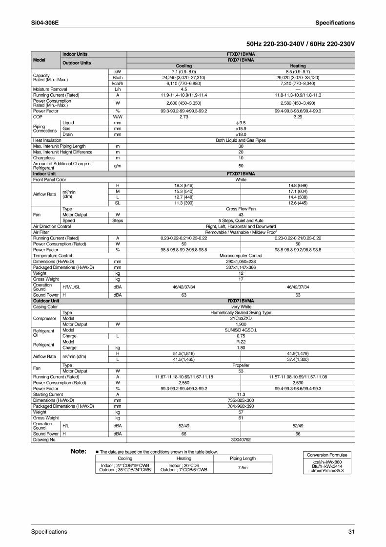
Si04-306E Specifications
50Hz 220-230-240V / 60Hz 220-230V
Note: The data are based on the conditions shown in the table below.
ModelIndoor Units FTXD71BVMA
Outdoor UnitsRXD71BVMA
Cooling Heating
Capacity Rated (Min.~Max.)
kW 7.1 (0.9~8.0) 8.5 (0.9~9.7)Btu/h 24,240 (3,070~27,310) 29,020 (3,070~33,120)kcal/h 6,110 (770~6,880) 7,310 (770~8,340)
Moisture Removal L/h 4.5 —Running Current (Rated) A 11.9-11.4-10.9/11.9-11.4 11.8-11.3-10.9/11.8-11.3Power Consumption Rated (Min.~Max.) W 2,600 (450~3,350) 2,580 (450~3,490)
Power Factor % 99.3-99.2-99.4/99.3-99.2 99.4-99.3-98.6/99.4-99.3COP W/W 2.73 3.29
Piping Connections
Liquid mm φ 9.5Gas mm φ15.9Drain mm φ18.0
Heat Insulation Both Liquid and Gas PipesMax. Interunit Piping Length m 30Max. Interunit Height Difference m 20Chargeless m 10Amount of Additional Charge ofRefrigerant g/m 50
Indoor Unit FTXD71BVMAFront Panel Color White
Airflow Rate m³/min (cfm)
H 18.3 (646) 19.8 (699)M 15.3 (540) 17.1 (604)L 12.7 (448) 14.4 (508)
SL 11.3 (399) 12.6 (445)
FanType Cross Flow FanMotor Output W 43Speed Steps 5 Steps, Quiet and Auto
Air Direction Control Right, Left, Horizontal and DownwardAir Filter Removable / Washable / Mildew ProofRunning Current (Rated) A 0.23-0.22-0.21/0.23-0.22 0.23-0.22-0.21/0.23-0.22Power Consumption (Rated) W 50 50Power Factor % 98.8-98.8-99.2/98.8-98.8 98.8-98.8-99.2/98.8-98.8Temperature Control Microcomputer ControlDimensions (H×W×D) mm 290×1,050×238Packaged Dimensions (H×W×D) mm 337×1,147×366Weight kg 12Gross Weight kg 17Operation Sound H/M/L/SL dBA 46/42/37/34 46/42/37/34
Sound Power H dBA 63 63Outdoor Unit RXD71BVMACasing Color Ivory White
CompressorType Hermetically Sealed Swing TypeModel 2YC63ZXDMotor Output W 1,900
Refrigerant Oil
Model SUNISO 4GSD.I.Charge L 0.75
RefrigerantModel R-22Charge kg 1.80
Airflow Rate m³/min (cfm)H 51.5(1,818) 41.9(1,479)L 41.5(1,465) 37.4(1,320)
FanType PropellerMotor Output W 53
Running Current (Rated) A 11.67-11.18-10.69/11.67-11.18 11.57-11.08-10.69/11.57-11.08Power Consumption (Rated) W 2,550 2,530Power Factor % 99.3-99.2-99.4/99.3-99.2 99.4-99.3-98.6/99.4-99.3Starting Current A 11.3Dimensions (H×W×D) mm 735×825×300Packaged Dimensions (H×W×D) mm 784×960×390Weight kg 57Gross Weight kg 61Operation Sound H/L dBA 52/49 52/49
Sound Power H dBA 66 66Drawing No. 3D040792
Conversion Formulae
kcal/h=kW×860Btu/h=kW×3414
cfm=m³/min×35.3
Cooling Heating Piping Length
Indoor ; 27°CDB/19°CWB Outdoor ; 35°CDB/24°CWB
Indoor ; 20°CDBOutdoor ; 7°CDB/6°CWB 7.5m
Specifications 31
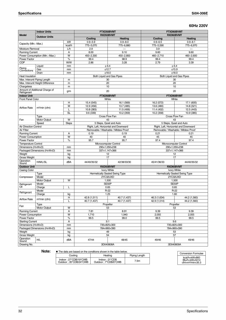
Specifications Si04-306E
60Hz 220V
Note: The data are based on the conditions shown in the table below.
ModelIndoor Units FTXD50BVMT FTXD60BVMT
Outdoor UnitsRXD50BVMT RXD60BVMT
Cooling Heating Cooling Heating
Capacity (Min.~Max.)kW 0.9~5.9 0.9~8.0 0.9~6.5 0.9~8.1
kcal/h 775~5,070 775~6,880 775~5,590 775~6,970Moisture Removal L/h 2.9 — 3.9 —Running Current A 8.00 9.10 9.60 9.60Power Consumption (Min.~Max.) W 450~2,300 450~2,800 460~2,710 460~2,600Power Factor % 99.4 98.9 99.4 99.4COP W/W 2.86 3.28 2.79 3.39
Piping Connections
Liquid mm φ 6.4 φ 6.4Gas mm φ12.7 φ15.9Drain mm φ18.0 φ18.0
Heat Insulation Both Liquid and Gas Pipes Both Liquid and Gas PipesMax. Interunit Piping Length m 30 30Max. Interunit Height Difference m 20 20Chargeless m 10 10Amount of Additional Charge ofRefrigerant g/m 20 20
Indoor Unit FTXD50BVMT FTXD60BVMTFront Panel Color White White
Airflow Rate m³/min (cfm)
H 15.4 (545) 16.1 (569) 16.2 (572) 17.1 (605)M 12.9 (456) 13.7 (485) 13.6 (480) 14.8 (521)L 10.8 (383) 11.5 (406) 11.4 (402) 12.5 (443)
SL 9.6 (339) 10.2 (359) 10.2 (358) 10.9 (385)
FanType Cross Flow Fan Cross Flow FanMotor Output W 43 43Speed Steps 5 Steps, Quiet and Auto 5 Steps, Quiet and Auto
Air Direction Control Right, Left, Horizontal and Downward Right, Left, Horizontal and DownwardAir Filter Removable / Washable / Mildew Proof Removable / Washable / Mildew ProofRunning Current A 0.19 0.19 0.21 0.21Power Consumption W 40 40 45 45Power Factor % 95.7 95.7 97.4 97.4Temperature Control Microcomputer Control Microcomputer ControlDimensions (H×W×D) mm 290×1,050×238 290×1,050×238Packaged Dimensions (H×W×D) mm 337×1,147×366 337×1,147×366Weight kg 12 12Gross Weight kg 17 17Operation Sound H/M/L/SL dBA 44/40/35/32 42/38/33/30 45/41/36/33 44/40/35/32
Outdoor Unit RXD50BVMT RXD60BVMTCasing Color Ivory White Ivory White
CompressorType Hermetically Sealed Swing Type Hermetically Sealed Swing TypeModel 2YC32UXD 2YC32UXDMotor Output W 1,500 1,500
Refrigerant Oil
Model SE50P SE50PCharge L 0.65 0.65
RefrigerantModel R-22 R-22Charge kg 1.25 1.60
Airflow Rate m³/min (cfm)H 42.8 (1,511) 40.7 (1,437) 46.3 (1,634) 44.2 (1,560)L 40.7 (1,437) 40.7 (1,437) 42.9 (1,514) 44.2 (1,560)
FanType Propeller PropellerMotor Output W 53 53
Running Current A 7.81 8.91 9.39 9.39Power Consumption W 1,710 1,940 2,055 2,055Power Factor % 99.5 99.0 99.5 99.5Starting Current A 9.1 9.6Dimensions (H×W×D) mm 735×825×300 735×825×300Packaged Dimensions (H×W×D) mm 784×960×390 784×960×390Weight kg 49 53Gross Weight kg 54 57Operation Sound H/L dBA 47/44 48/45 49/46 49/46
Drawing No. 3D040808A 3D040809A
Conversion Formulae
kcal/h=kW×860Btu/h=kW×3414
cfm=m³/min×35.3
Cooling Heating Piping Length
Indoor ; 27°CDB/19°CWB Outdoor ; 35°CDB/24°CWB
Indoor ; 21°CDBOutdoor ; 7°CDB/6°CWB 7.5m
32 Specifications
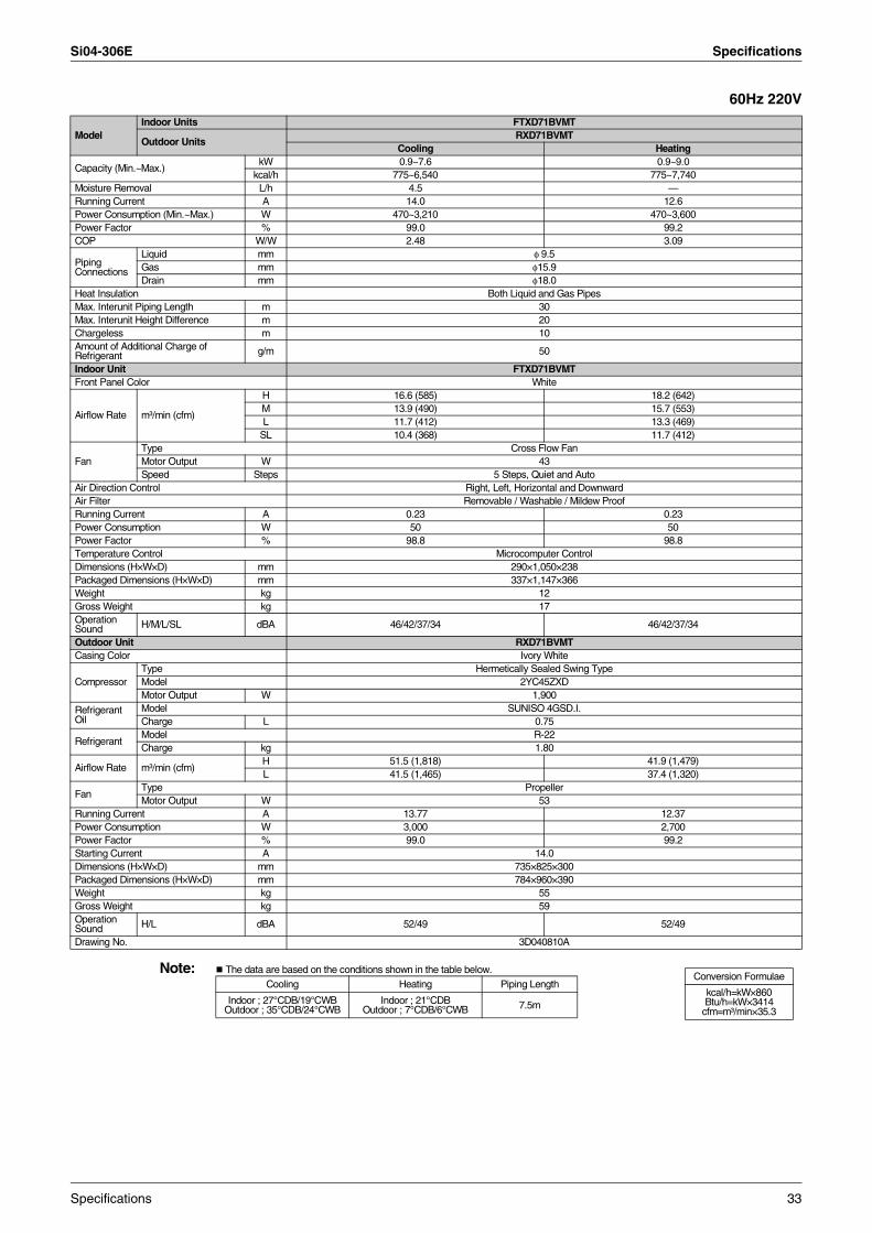
Si04-306E Specifications
60Hz 220V
Note: The data are based on the conditions shown in the table below.
ModelIndoor Units FTXD71BVMT
Outdoor UnitsRXD71BVMT
Cooling Heating
Capacity (Min.~Max.)kW 0.9~7.6 0.9~9.0
kcal/h 775~6,540 775~7,740Moisture Removal L/h 4.5 —Running Current A 14.0 12.6Power Consumption (Min.~Max.) W 470~3,210 470~3,600Power Factor % 99.0 99.2COP W/W 2.48 3.09
Piping Connections
Liquid mm φ 9.5Gas mm φ15.9Drain mm φ18.0
Heat Insulation Both Liquid and Gas PipesMax. Interunit Piping Length m 30Max. Interunit Height Difference m 20Chargeless m 10Amount of Additional Charge ofRefrigerant g/m 50
Indoor Unit FTXD71BVMTFront Panel Color White
Airflow Rate m³/min (cfm)
H 16.6 (585) 18.2 (642)M 13.9 (490) 15.7 (553)L 11.7 (412) 13.3 (469)
SL 10.4 (368) 11.7 (412)
FanType Cross Flow FanMotor Output W 43Speed Steps 5 Steps, Quiet and Auto
Air Direction Control Right, Left, Horizontal and DownwardAir Filter Removable / Washable / Mildew ProofRunning Current A 0.23 0.23Power Consumption W 50 50Power Factor % 98.8 98.8Temperature Control Microcomputer ControlDimensions (H×W×D) mm 290×1,050×238Packaged Dimensions (H×W×D) mm 337×1,147×366Weight kg 12Gross Weight kg 17Operation Sound H/M/L/SL dBA 46/42/37/34 46/42/37/34
Outdoor Unit RXD71BVMTCasing Color Ivory White
CompressorType Hermetically Sealed Swing TypeModel 2YC45ZXDMotor Output W 1,900
Refrigerant Oil
Model SUNISO 4GSD.I.Charge L 0.75
RefrigerantModel R-22Charge kg 1.80
Airflow Rate m³/min (cfm)H 51.5 (1,818) 41.9 (1,479)L 41.5 (1,465) 37.4 (1,320)
FanType PropellerMotor Output W 53
Running Current A 13.77 12.37Power Consumption W 3,000 2,700Power Factor % 99.0 99.2Starting Current A 14.0Dimensions (H×W×D) mm 735×825×300Packaged Dimensions (H×W×D) mm 784×960×390Weight kg 55Gross Weight kg 59Operation Sound H/L dBA 52/49 52/49
Drawing No. 3D040810A
Conversion Formulae
kcal/h=kW×860Btu/h=kW×3414
cfm=m³/min×35.3
Cooling Heating Piping Length
Indoor ; 27°CDB/19°CWB Outdoor ; 35°CDB/24°CWB
Indoor ; 21°CDBOutdoor ; 7°CDB/6°CWB 7.5m
Specifications 33
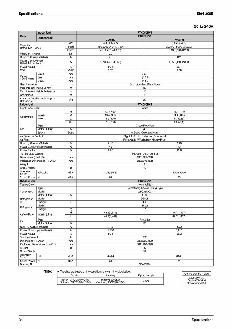
Specifications Si04-306E
50Hz 240V
Note: The data are based on the conditions shown in the table below.
ModelIndoor Unit FTXD50BV4
Outdoor UnitRXD50BV4
Cooling Heating
Capacity Rated (Min.~Max.)
kW 4.8 (0.9~5.2) 6.0 (0.9~7.3)Btu/h 16,390 (3,070~17,750) 20,480 (3,070~24,920)kcal/h 4,130 (770~4,470) 5,160 (770~6,280)
Moisture Removal L/h 2.9 —Running Current (Rated) A 7.3 8.2 Power Consumption Rated (Min.~Max.) W 1,740 (450~1,950) 1,950 (450~2,300)
Power Factor % 99.3 99.1COP W/W 2.76 3.08
Piping Connections
Liquid mm φ 6.4Gas mm φ12.7Drain mm φ18.0
Heat Insulation Both Liquid and Gas PipesMax. Interunit Piping Length m 30Max. Interunit Height Difference m 20Chargeless m 10Amount of Additional Charge ofRefrigerant g/m 20
Indoor Unit FTXD50BV4Front Panel Color White
Airflow Rate m³/min (cfm)
H 12.3 (433) 13.4 (474)M 10.4 (366) 11.4 (402)L 8.6 (303) 9.3 (329)
SL 7.6 (268) 8.2 (291)
FanType Cross Flow FanMotor Output W 40Speed Steps 5 Steps, Quiet and Auto
Air Direction Control Right, Left, Horizontal and DownwardAir Filter Removable / Washable / Mildew ProofRunning Current (Rated) A 0.18 0.18Power Consumption (Rated) W 40 40Power Factor % 92.6 92.6Temperature Control Microcomputer ControlDimensions (H×W×D) mm 290×795×238Packaged Dimensions (H×W×D) mm 280×840×338Weight kg 9Gross Weight kg 13Operation Sound H/M/L/SL dBA 44/40/35/32 42/38/33/30
Sound Power H dBA 63 60Outdoor Unit RXD50BV4Casing Color Ivory White
CompressorType Hermetically Sealed Swing TypeModel 2YC32UXDMotor Output W 1,500
Refrigerant Oil
Model SE50PCharge L 0.65
RefrigerantModel R-22Charge kg 1.25
Airflow Rate m³/min (cfm)H 42.8(1,511) 40.7(1,437)L 40.7(1,437) 40.7(1,437)
FanType PropellerMotor Output W 53
Running Current (Rated) A 7.12 8.02Power Consumption (Rated) W 1,700 1,910Power Factor % 99.5 99.2Starting Current A 7.2Dimensions (H×W×D) mm 735×825×300Packaged Dimensions (H×W×D) mm 784×960×390Weight kg 49Gross Weight kg 54Operation Sound H/L dBA 47/44 48/45
Sound Power H dBA 63 64Drawing No. 3D040788
Conversion Formulae
kcal/h=kW×860Btu/h=kW×3414
cfm=m³/min×35.3
Cooling Heating Piping Length
Indoor ; 27°CDB/19°CWB Outdoor ; 35°CDB/24°CWB
Indoor ; 20°CDBOutdoor ; 7°CDB/6°CWB 7.5m
34 Specifications
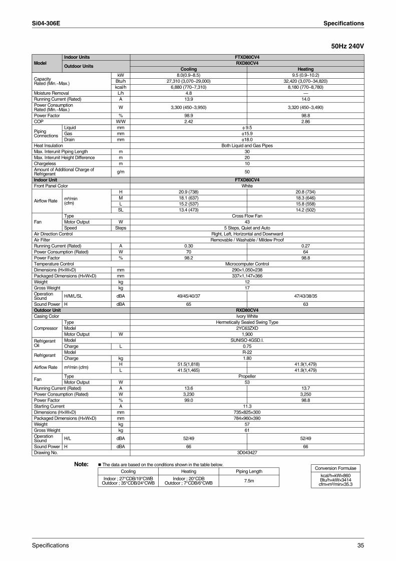
Si04-306E Specifications
50Hz 240V
Note: The data are based on the conditions shown in the table below.
ModelIndoor Units FTXD80CV4
Outdoor UnitsRXD80CV4
Cooling Heating
Capacity Rated (Min.~Max.)
kW 8.0(0.9~8.5) 9.5 (0.9~10.2)Btu/h 27,310 (3,070~29,000) 32,420 (3,070~34,820)kcal/h 6,880 (770~7,310) 8,180 (770~8,780)
Moisture Removal L/h 4.8 —Running Current (Rated) A 13.9 14.0Power Consumption Rated (Min.~Max.) W 3,300 (450~3,950) 3,320 (450~3,490)
Power Factor % 98.9 98.8COP W/W 2.42 2.86
Piping Connections
Liquid mm φ 9.5Gas mm φ15.9Drain mm φ18.0
Heat Insulation Both Liquid and Gas PipesMax. Interunit Piping Length m 30Max. Interunit Height Difference m 20Chargeless m 10Amount of Additional Charge ofRefrigerant g/m 50
Indoor Unit FTXD80CV4Front Panel Color White
Airflow Rate m³/min (cfm)
H 20.9 (738) 20.8 (734)M 18.1 (637) 18.3 (646)L 15.2 (537) 15.8 (558)
SL 13.4 (473) 14.2 (502)
FanType Cross Flow FanMotor Output W 43Speed Steps 5 Steps, Quiet and Auto
Air Direction Control Right, Left, Horizontal and DownwardAir Filter Removable / Washable / Mildew ProofRunning Current (Rated) A 0.30 0.27Power Consumption (Rated) W 70 64Power Factor % 98.2 98.8Temperature Control Microcomputer ControlDimensions (H×W×D) mm 290×1,050×238Packaged Dimensions (H×W×D) mm 337×1,147×366Weight kg 12Gross Weight kg 17Operation Sound H/M/L/SL dBA 49/45/40/37 47/43/38/35
Sound Power H dBA 65 63Outdoor Unit RXD80CV4Casing Color Ivory White
CompressorType Hermetically Sealed Swing TypeModel 2YC63ZXDMotor Output W 1,900
Refrigerant Oil
Model SUNISO 4GSD.I.Charge L 0.75
RefrigerantModel R-22Charge kg 1.80
Airflow Rate m³/min (cfm)H 51.5(1,818) 41.9(1,479)L 41.5(1,465) 41.9(1,479)
FanType PropellerMotor Output W 53
Running Current (Rated) A 13.6 13.7Power Consumption (Rated) W 3,230 3,250Power Factor % 99.0 98.8Starting Current A 11.3Dimensions (H×W×D) mm 735×825×300Packaged Dimensions (H×W×D) mm 784×960×390Weight kg 57Gross Weight kg 61Operation Sound H/L dBA 52/49 52/49
Sound Power H dBA 66 66Drawing No. 3D043427
Conversion Formulae
kcal/h=kW×860Btu/h=kW×3414
cfm=m³/min×35.3
Cooling Heating Piping Length
Indoor ; 27°CDB/19°CWB Outdoor ; 35°CDB/24°CWB
Indoor ; 20°CDBOutdoor ; 7°CDB/6°CWB 7.5m
Specifications 35
Specifications Si04-306E
36 Specifications
Si04-306E
Printed Circuit Board Connector Wiring Diagram 37
Part 3Printed Circuit Board
Connector Wiring Diagram
1. Printed Circuit Board Connector Wiring Diagram..................................381.1 Indoor Unit..............................................................................................381.2 Outdoor Unit ...........................................................................................40
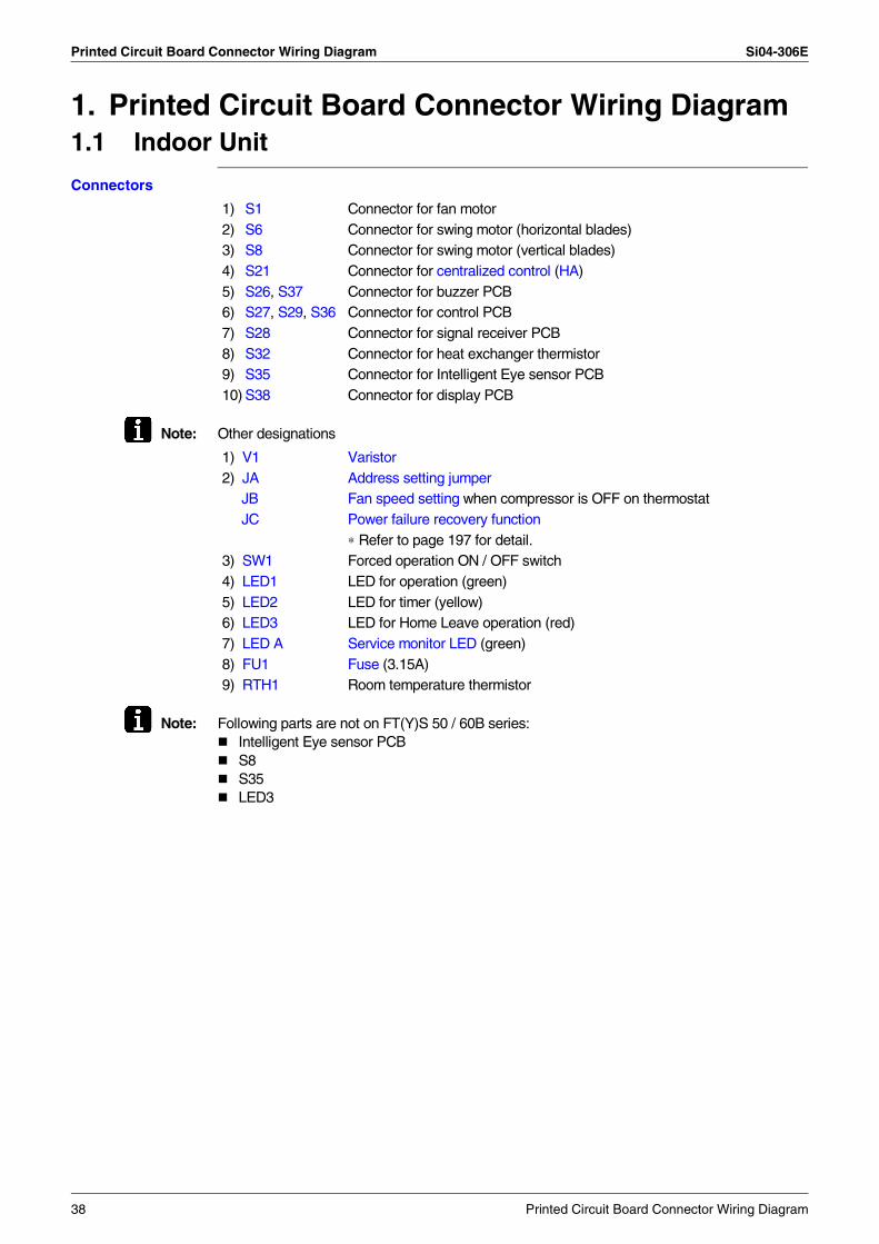
Printed Circuit Board Connector Wiring Diagram Si04-306E
1. Printed Circuit Board Connector Wiring Diagram1.1 Indoor Unit
Connectors
Note: Other designations
Note: Following parts are not on FT(Y)S 50 / 60B series:Intelligent Eye sensor PCBS8S35LED3
1) S1 Connector for fan motor2) S6 Connector for swing motor (horizontal blades)3) S8 Connector for swing motor (vertical blades)4) S21 Connector for centralized control (HA)5) S26, S37 Connector for buzzer PCB6) S27, S29, S36 Connector for control PCB7) S28 Connector for signal receiver PCB8) S32 Connector for heat exchanger thermistor9) S35 Connector for Intelligent Eye sensor PCB10) S38 Connector for display PCB
1) V1 Varistor2) JA Address setting jumper JB Fan speed setting when compressor is OFF on thermostat JC Power failure recovery function ∗ Refer to page 197 for detail.3) SW1 Forced operation ON / OFF switch4) LED1 LED for operation (green)5) LED2 LED for timer (yellow)6) LED3 LED for Home Leave operation (red)7) LED A Service monitor LED (green)8) FU1 Fuse (3.15A)9) RTH1 Room temperature thermistor
38 Printed Circuit Board Connector Wiring Diagram
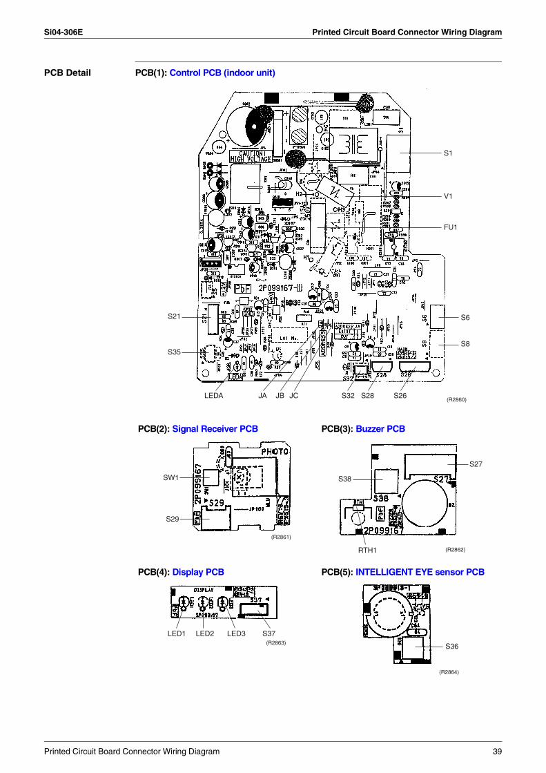
Si04-306E Printed Circuit Board Connector Wiring Diagram
PCB Detail PCB(1): Control PCB (indoor unit)
PCB(2): Signal Receiver PCB PCB(3): Buzzer PCB
PCB(4): Display PCB PCB(5): INTELLIGENT EYE sensor PCB
S1
V1
FU1
S6
S8
S26(R2860)
S28S32JCJBJALEDA
S21
S35
SW1
S29
(R2861)
(R2862)RTH1
S38
S27
LED1 LED2 LED3 S37(R2863) S36
(R2864)
Printed Circuit Board Connector Wiring Diagram 39
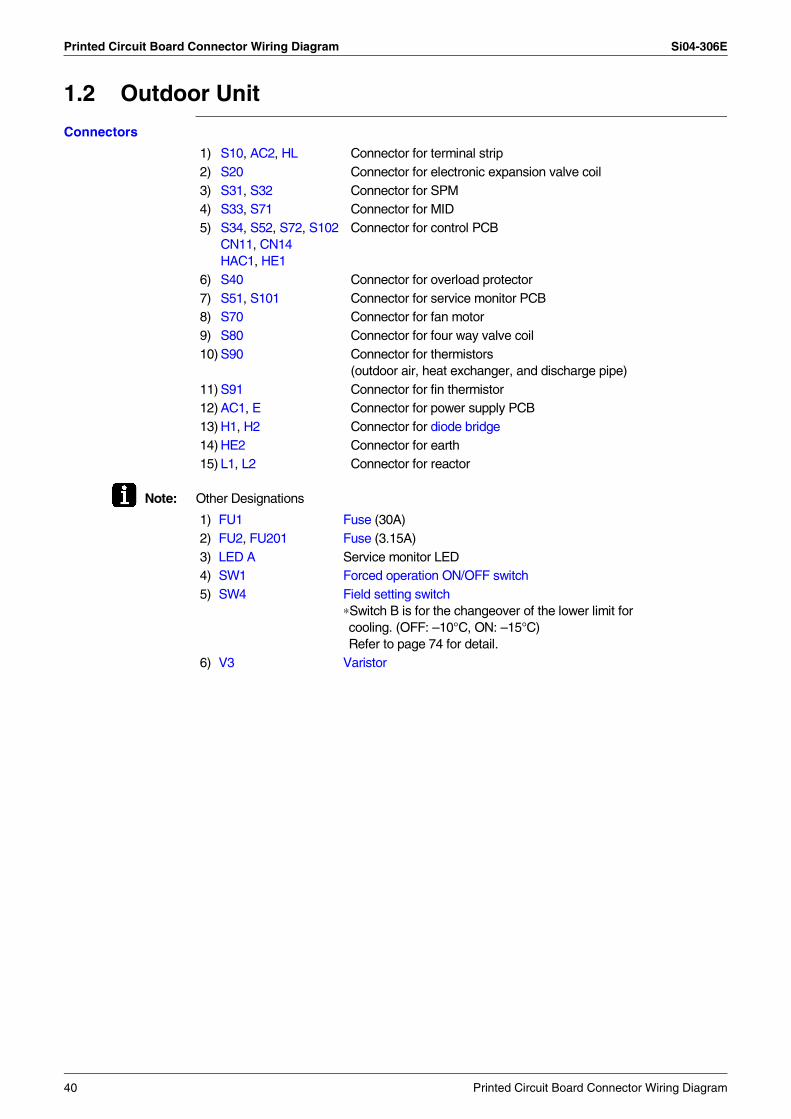
Printed Circuit Board Connector Wiring Diagram Si04-306E
1.2 Outdoor Unit
Connectors
Note: Other Designations
1) S10, AC2, HL Connector for terminal strip2) S20 Connector for electronic expansion valve coil3) S31, S32 Connector for SPM4) S33, S71 Connector for MID5) S34, S52, S72, S102
CN11, CN14HAC1, HE1
Connector for control PCB
6) S40 Connector for overload protector7) S51, S101 Connector for service monitor PCB8) S70 Connector for fan motor9) S80 Connector for four way valve coil10) S90 Connector for thermistors
(outdoor air, heat exchanger, and discharge pipe)11) S91 Connector for fin thermistor12) AC1, E Connector for power supply PCB13) H1, H2 Connector for diode bridge14) HE2 Connector for earth15) L1, L2 Connector for reactor
1) FU1 Fuse (30A)2) FU2, FU201 Fuse (3.15A)3) LED A Service monitor LED4) SW1 Forced operation ON/OFF switch5) SW4 Field setting switch
∗Switch B is for the changeover of the lower limit for cooling. (OFF: –10°C, ON: –15°C)Refer to page 74 for detail.
6) V3 Varistor
40 Printed Circuit Board Connector Wiring Diagram
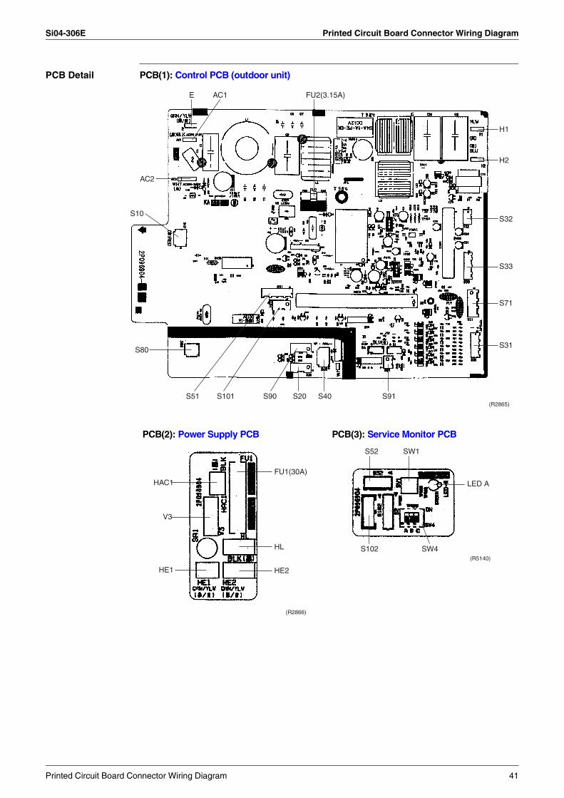
Si04-306E Printed Circuit Board Connector Wiring Diagram
PCB Detail PCB(1): Control PCB (outdoor unit)
E AC1 FU2(3.15A)
H1
H2
S32
S33
S71
S31
S91(R2865)
S40S20S90S101S51
S80
S10
AC2
PCB(2): Power Supply PCB PCB(3): Service Monitor PCB
HAC1
V3
HE1 HE2
(R2866)
HL
FU1(30A)
S52
S102 SW4(R5140)
SW1
LED A
Printed Circuit Board Connector Wiring Diagram 41
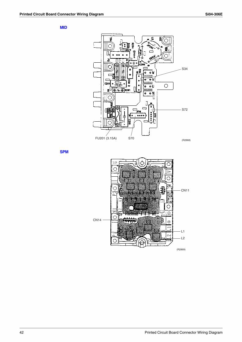
Printed Circuit Board Connector Wiring Diagram Si04-306E
MID
SPM
S34
S72
(R2868)S70FU201 (3.15A)
(R2869)
CN14
CN11
L1
L2
42 Printed Circuit Board Connector Wiring Diagram
Si04-306E
Function and Control 43
Part 4Function and Control
1. Main Functions......................................................................................441.1 Frequency Principle................................................................................441.2 Power-Airflow Dual Flaps, Wide Angle Louvers and Auto-Swing ..........461.3 Fan Speed Control for Indoor Units........................................................471.4 Programme Dry Function .......................................................................481.5 Automatic Operation...............................................................................491.6 Thermostat Control.................................................................................501.7 Night Set Mode.......................................................................................511.8 INTELLIGENT EYE................................................................................521.9 HOME LEAVE Operation .......................................................................541.10 Inverter POWERFUL Operation .............................................................551.11 Other Functions......................................................................................56
2. Function of Main Structural Parts..........................................................582.1 Function of Thermistor ...........................................................................58
3. Control Specification .............................................................................603.1 Mode Hierarchy ......................................................................................603.2 Frequency Control..................................................................................613.3 Controls at Mode Changing / Start-up....................................................633.4 Discharge Pipe Temperature Control.....................................................643.5 Input Current Control..............................................................................643.6 Freeze-up Protection Control .................................................................653.7 Heating Peak-cut Control .......................................................................653.8 Fan Control.............................................................................................663.9 Liquid Compression Protection Function 2.............................................663.10 Low Hz High Pressure Limit ...................................................................673.11 Defrost Control .......................................................................................673.12 Electronic Expansion Valve Control .......................................................683.13 Malfunctions ...........................................................................................713.14 Forced Operation Mode .........................................................................733.15 Additional Function.................................................................................733.16 Facility Setting Switch (cooling at low outdoor temperature)..................74
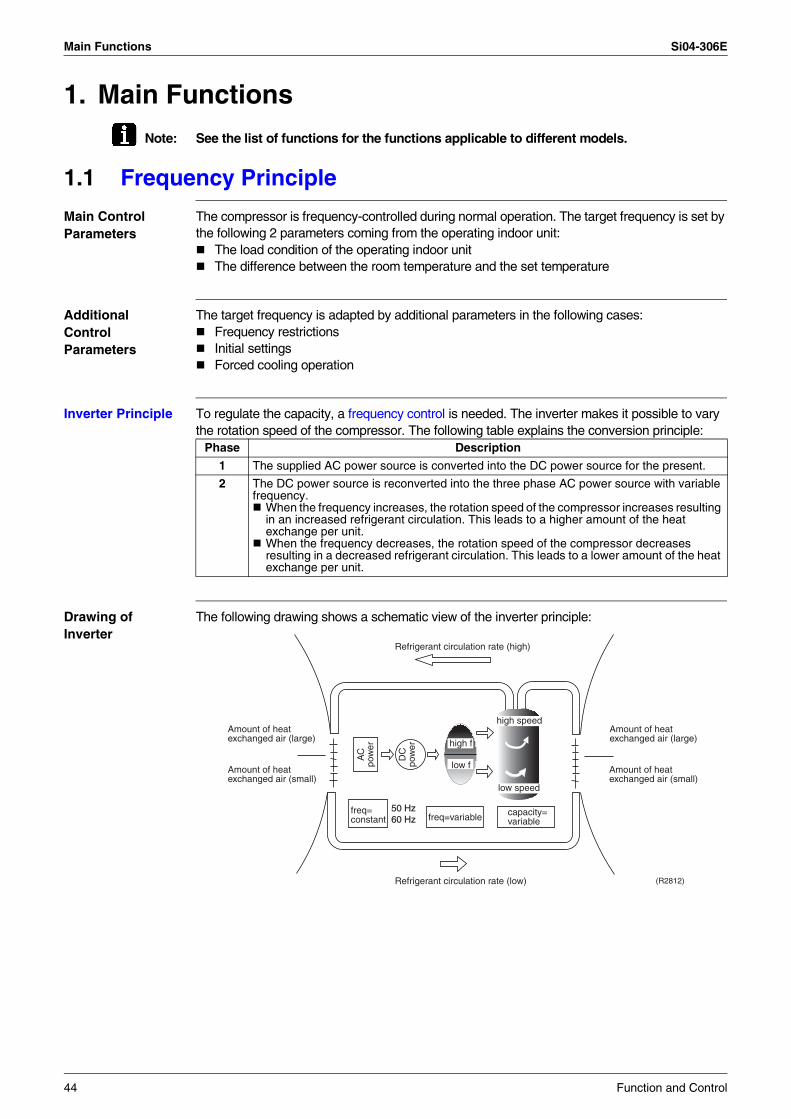
Main Functions Si04-306E
1. Main FunctionsNote: See the list of functions for the functions applicable to different models.
1.1 Frequency Principle
Main Control Parameters
The compressor is frequency-controlled during normal operation. The target frequency is set by the following 2 parameters coming from the operating indoor unit:
The load condition of the operating indoor unitThe difference between the room temperature and the set temperature
Additional Control Parameters
The target frequency is adapted by additional parameters in the following cases:Frequency restrictionsInitial settingsForced cooling operation
Inverter Principle To regulate the capacity, a frequency control is needed. The inverter makes it possible to vary the rotation speed of the compressor. The following table explains the conversion principle:
Drawing of Inverter
The following drawing shows a schematic view of the inverter principle:
Phase Description
1 The supplied AC power source is converted into the DC power source for the present.
2 The DC power source is reconverted into the three phase AC power source with variable frequency.
When the frequency increases, the rotation speed of the compressor increases resulting in an increased refrigerant circulation. This leads to a higher amount of the heat exchange per unit.When the frequency decreases, the rotation speed of the compressor decreases resulting in a decreased refrigerant circulation. This leads to a lower amount of the heat exchange per unit.
50 Hz60 Hz
Refrigerant circulation rate (high)
Amount of heatexchanged air (large)
Amount of heatexchanged air (small)
AC
pow
er
freq=constant
DC
pow
er
Amount of heatexchanged air (large)
Amount of heatexchanged air (small)
high f
low f
freq=variable capacity=variable
Refrigerant circulation rate (low)
high speed
low speed
(R2812)
44 Function and Control
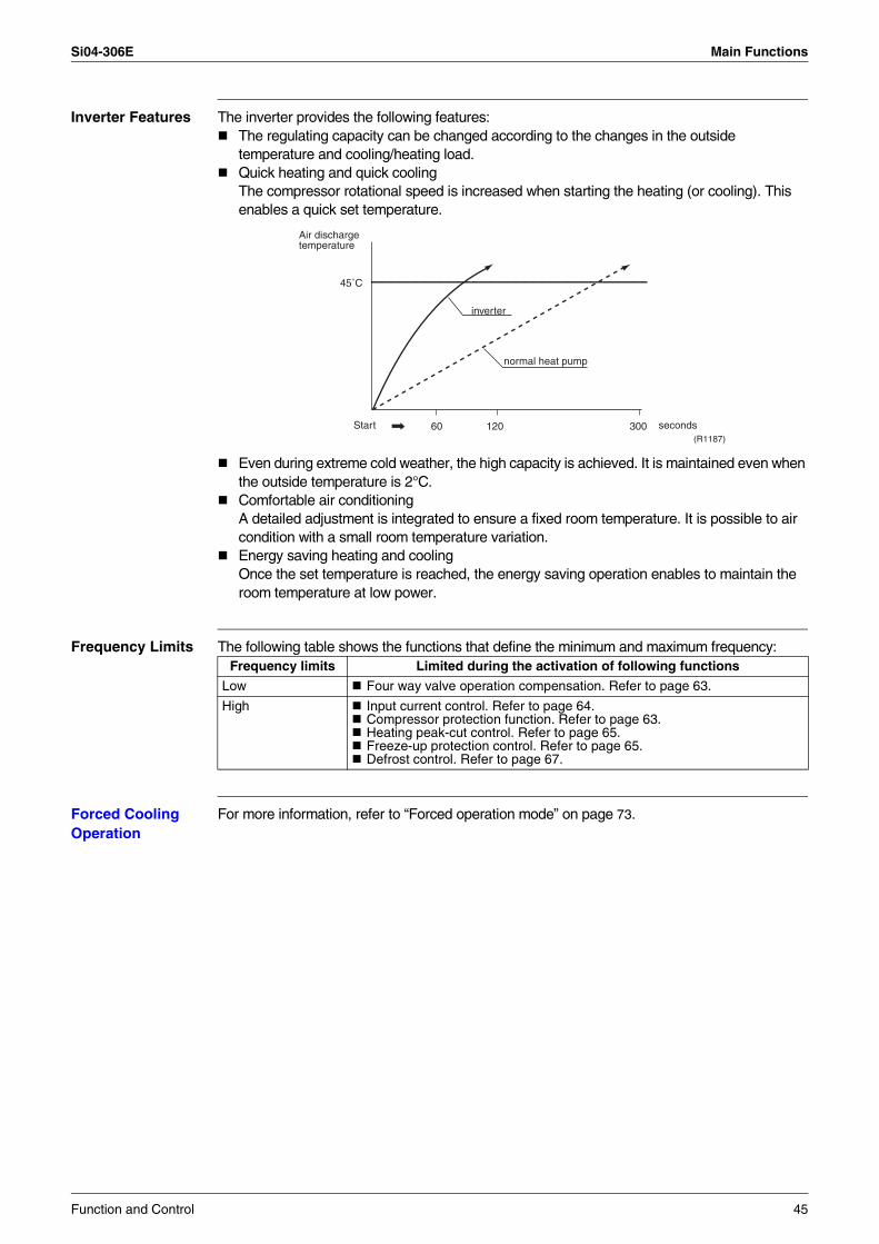
Si04-306E Main Functions
Inverter Features The inverter provides the following features:The regulating capacity can be changed according to the changes in the outside temperature and cooling/heating load.Quick heating and quick coolingThe compressor rotational speed is increased when starting the heating (or cooling). This enables a quick set temperature.
Even during extreme cold weather, the high capacity is achieved. It is maintained even when the outside temperature is 2°C.Comfortable air conditioning A detailed adjustment is integrated to ensure a fixed room temperature. It is possible to air condition with a small room temperature variation.Energy saving heating and coolingOnce the set temperature is reached, the energy saving operation enables to maintain the room temperature at low power.
Frequency Limits The following table shows the functions that define the minimum and maximum frequency:
Forced Cooling Operation
For more information, refer to “Forced operation mode” on page 73.
60 120 300
45˚C
Air dischargetemperature
inverter
normal heat pump
Start seconds(R1187)
Frequency limits Limited during the activation of following functions
Low Four way valve operation compensation. Refer to page 63.
High Input current control. Refer to page 64.Compressor protection function. Refer to page 63.Heating peak-cut control. Refer to page 65.Freeze-up protection control. Refer to page 65.Defrost control. Refer to page 67.
Function and Control 45
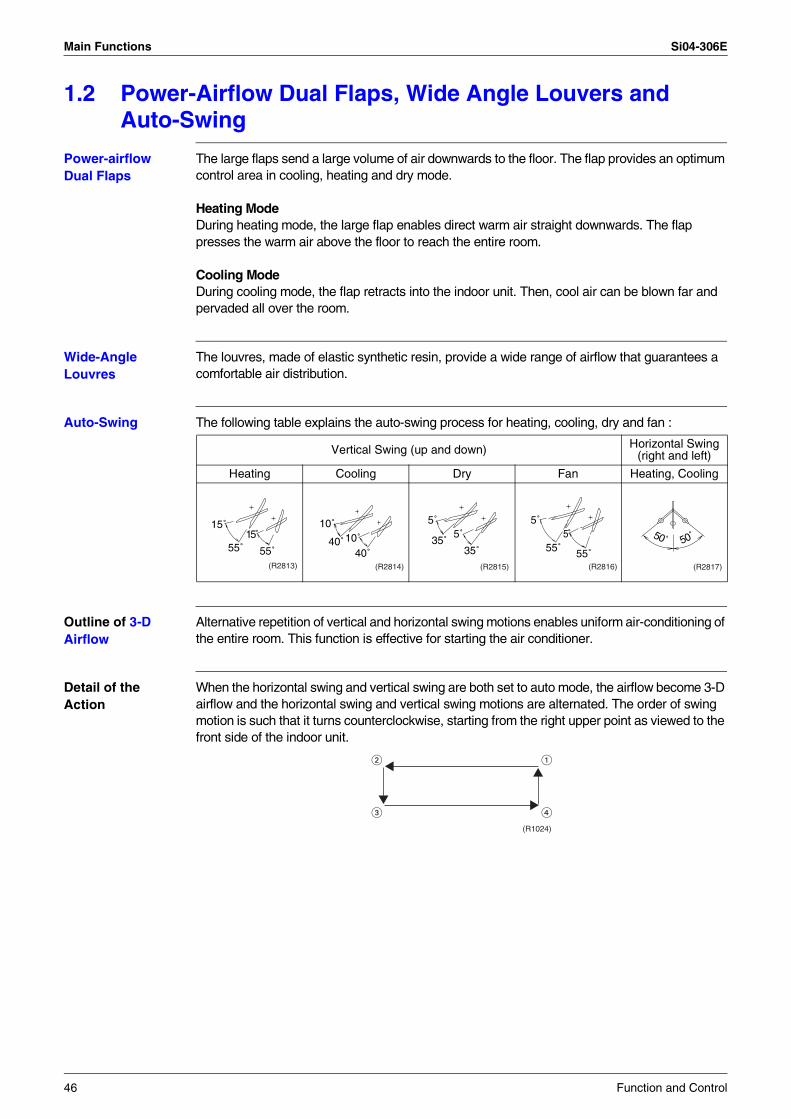
Main Functions Si04-306E
1.2 Power-Airflow Dual Flaps, Wide Angle Louvers and Auto-Swing
Power-airflow Dual Flaps
The large flaps send a large volume of air downwards to the floor. The flap provides an optimum control area in cooling, heating and dry mode.
Heating ModeDuring heating mode, the large flap enables direct warm air straight downwards. The flap presses the warm air above the floor to reach the entire room.
Cooling ModeDuring cooling mode, the flap retracts into the indoor unit. Then, cool air can be blown far and pervaded all over the room.
Wide-Angle Louvres
The louvres, made of elastic synthetic resin, provide a wide range of airflow that guarantees a comfortable air distribution.
Auto-Swing The following table explains the auto-swing process for heating, cooling, dry and fan :
Outline of 3-D Airflow
Alternative repetition of vertical and horizontal swing motions enables uniform air-conditioning of the entire room. This function is effective for starting the air conditioner.
Detail of the Action
When the horizontal swing and vertical swing are both set to auto mode, the airflow become 3-D airflow and the horizontal swing and vertical swing motions are alternated. The order of swing motion is such that it turns counterclockwise, starting from the right upper point as viewed to the front side of the indoor unit.
Vertical Swing (up and down) Horizontal Swing (right and left)
Heating Cooling Dry Fan Heating, Cooling
15˚
55˚15
55˚(R2813)
10˚
40˚10˚40˚
(R2814)
5˚
35˚5˚
35˚
(R2815)
5˚
55˚5
55˚(R2816)
50˚ 50˚
(R2817)
(R1024)
46 Function and Control
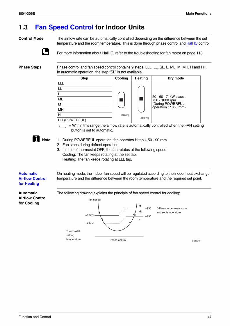
Si04-306E Main Functions
1.3 Fan Speed Control for Indoor Units
Control Mode The airflow rate can be automatically controlled depending on the difference between the set temperature and the room temperature. This is done through phase control and Hall IC control.
For more information about Hall IC, refer to the troubleshooting for fan motor on page 113.
Phase Steps Phase control and fan speed control contains 9 steps: LLL, LL, SL, L, ML, M, MH, H and HH.In automatic operation, the step “SL” is not available.
= Within this range the airflow rate is automatically controlled when the FAN setting button is set to automatic.
Note: 1. During POWERFUL operation, fan operates H tap + 50 - 90 rpm.2. Fan stops during defrost operation.3. In time of thermostat OFF, the fan rotates at the following speed.
Cooling: The fan keeps rotating at the set tap.Heating: The fan keeps rotating at LLL tap.
Automatic Airflow Control for Heating
On heating mode, the indoor fan speed will be regulated according to the indoor heat exchanger temperature and the difference between the room temperature and the required set point.
Automatic Airflow Control for Cooling
The following drawing explains the principle of fan speed control for cooling:
Step Cooling Heating Dry mode
LLL
50 · 60 · 71kW class : 750 - 1000 rpm(During POWERFUL operation : 1050 rpm)
LL
L
ML
M
MH
H
HH (POWERFUL)
(R2818)(R5229)
+1.5˚C
+0.5˚C
+2˚C
+1˚C
M
ML
L
fan speed
Difference between room
and set temperature
Phase control
Thermostat
setting
temperature (R2820)
Function and Control 47
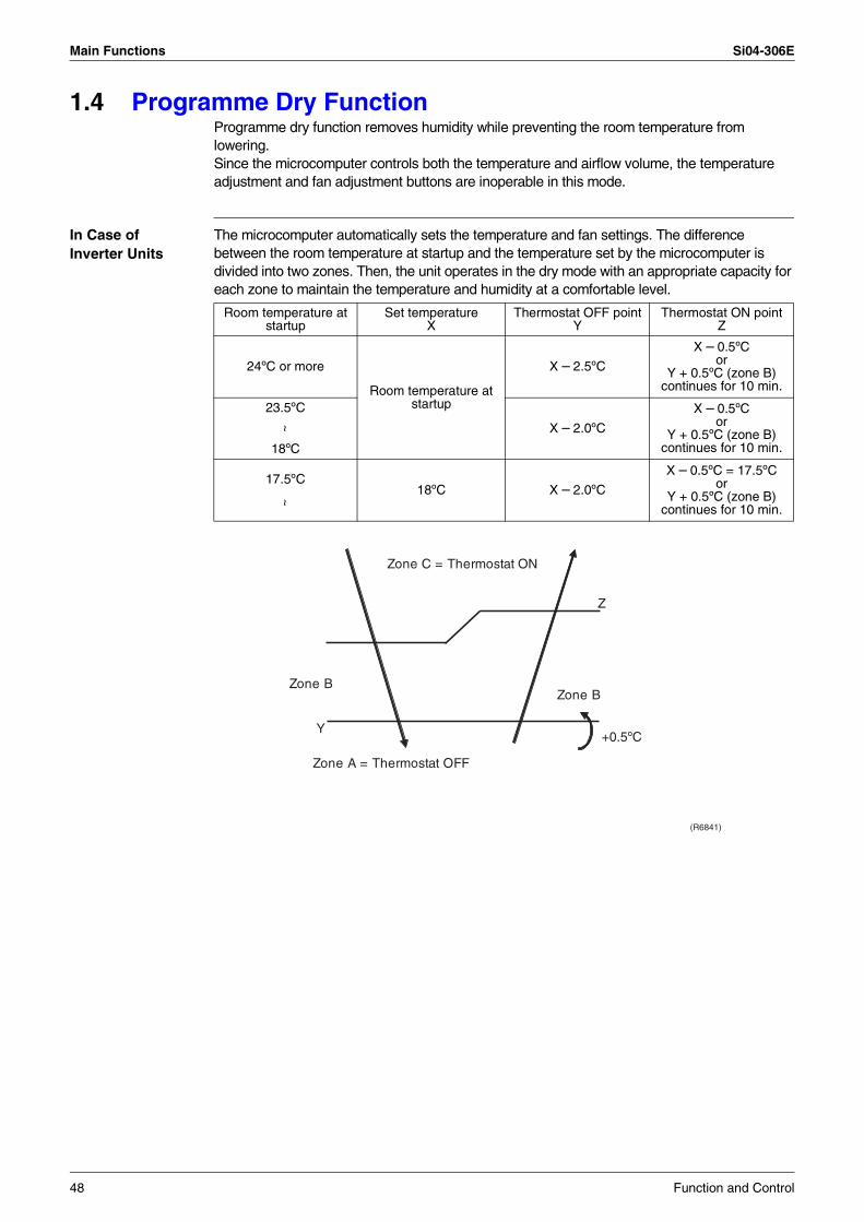
Main Functions Si04-306E
1.4 Programme Dry FunctionProgramme dry function removes humidity while preventing the room temperature from lowering.Since the microcomputer controls both the temperature and airflow volume, the temperature adjustment and fan adjustment buttons are inoperable in this mode.
In Case of Inverter Units
The microcomputer automatically sets the temperature and fan settings. The difference between the room temperature at startup and the temperature set by the microcomputer is divided into two zones. Then, the unit operates in the dry mode with an appropriate capacity for each zone to maintain the temperature and humidity at a comfortable level.
Room temperature at startup
Set temperature X
Thermostat OFF pointY
Thermostat ON pointZ
24ºC or more
Room temperature at startup
X – 2.5ºC
X – 0.5ºCor
Y + 0.5ºC (zone B) continues for 10 min.
23.5ºC
X – 2.0ºC
X – 0.5ºCor
Y + 0.5ºC (zone B) continues for 10 min.
~
18ºC
18ºC X – 2.0ºC
X – 0.5ºC = 17.5ºCor
Y + 0.5ºC (zone B) continues for 10 min.
17.5ºC
~
Z
Y
Zone BZone B
Zone A = Thermostat OFF
Zone C = Thermostat ON
+0.5ºC
(R6841)
48 Function and Control
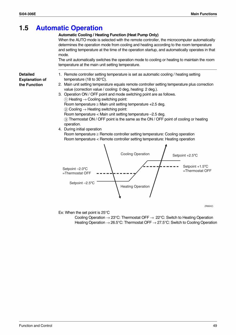
Si04-306E Main Functions
1.5 Automatic OperationAutomatic Cooling / Heating Function (Heat Pump Only)When the AUTO mode is selected with the remote controller, the microcomputer automatically determines the operation mode from cooling and heating according to the room temperature and setting temperature at the time of the operation startup, and automatically operates in that mode.The unit automatically switches the operation mode to cooling or heating to maintain the room temperature at the main unit setting temperature.
Detailed Explanation of the Function
1. Remote controller setting temperature is set as automatic cooling / heating setting temperature (18 to 30°C).
2. Main unit setting temperature equals remote controller setting temperature plus correction value (correction value / cooling: 0 deg, heating: 2 deg.).
3. Operation ON / OFF point and mode switching point are as follows. Heating → Cooling switching point: Room temperature ≥ Main unit setting temperature +2.5 deg. Cooling → Heating switching point: Room temperature < Main unit setting temperature –2.5 deg. Thermostat ON / OFF point is the same as the ON / OFF point of cooling or heating operation.
4. During initial operationRoom temperature ≥ Remote controller setting temperature: Cooling operationRoom temperature < Remote controller setting temperature: Heating operation
Ex: When the set point is 25°CCooling Operation → 23°C: Thermostat OFF → 22°C: Switch to Heating OperationHeating Operation → 26.5°C: Thermostat OFF → 27.5°C: Switch to Cooling Operation
(R6842)
Setpoint +2.5ºC
Setpoint –2.0ºC=Thermostat OFF
Setpoint +1.5ºC=Thermostat OFF
Heating OperationSetpoint –2.5ºC
Cooling Operation
Function and Control 49
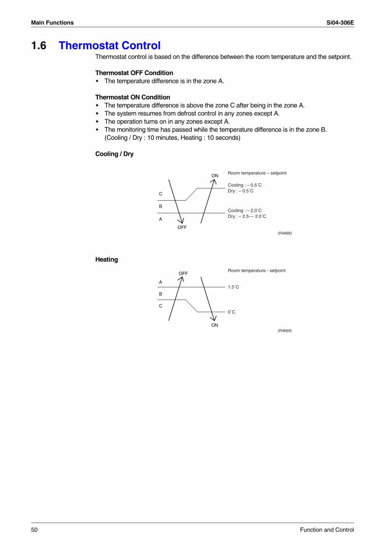
Main Functions Si04-306E
1.6 Thermostat ControlThermostat control is based on the difference between the room temperature and the setpoint.
Thermostat OFF ConditionThe temperature difference is in the zone A.
Thermostat ON ConditionThe temperature difference is above the zone C after being in the zone A.The system resumes from defrost control in any zones except A.The operation turns on in any zones except A.The monitoring time has passed while the temperature difference is in the zone B.(Cooling / Dry : 10 minutes, Heating : 10 seconds)
Cooling / Dry
Heating
B
A
OFF
ON
C
Cooling : – 0.5˚CDry : – 0.5˚C
Room temperature – setpoint
Cooling : – 2.0˚CDry : – 2.5~– 2.0˚C
(R4668)
B
A
OFF
ON
C
1.5˚C
Room temperature - setpoint
0˚C
(R4669)
50 Function and Control
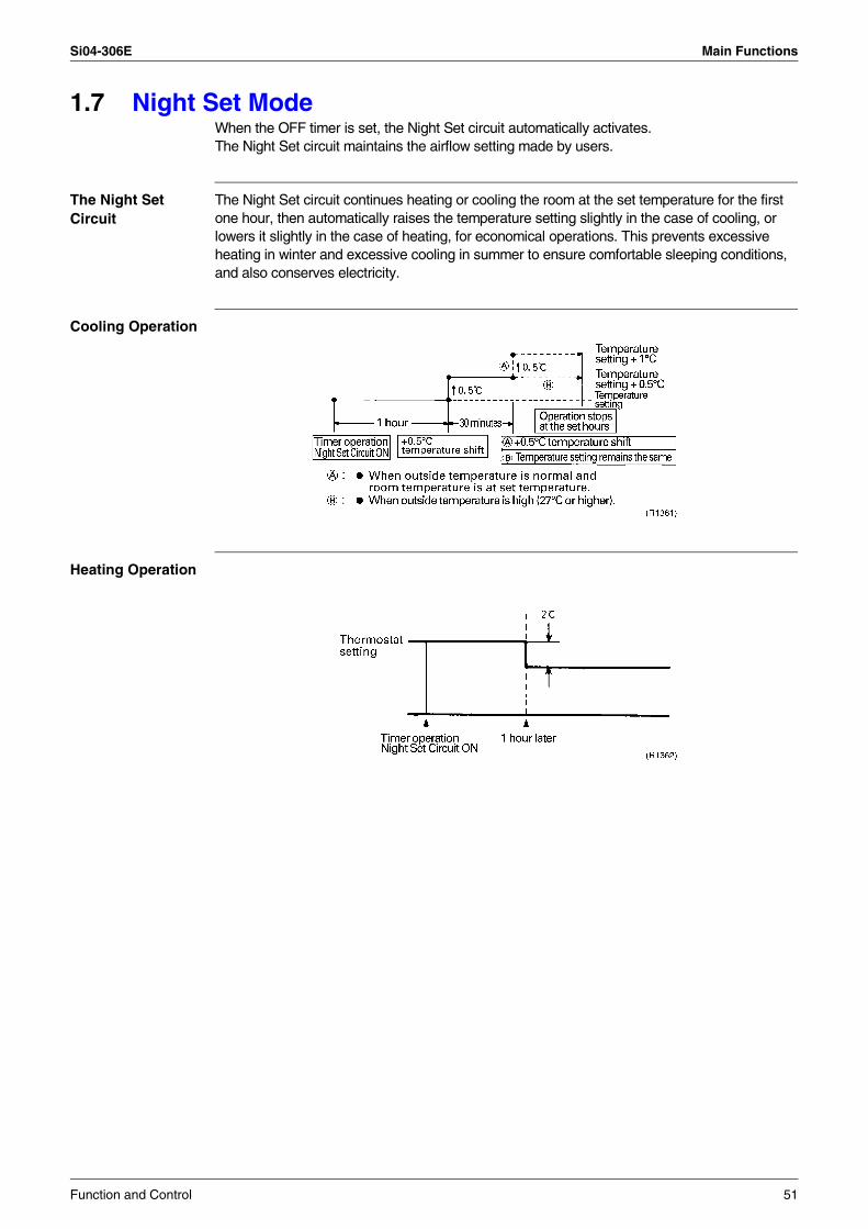
Si04-306E Main Functions
1.7 Night Set ModeWhen the OFF timer is set, the Night Set circuit automatically activates.The Night Set circuit maintains the airflow setting made by users.
The Night Set Circuit
The Night Set circuit continues heating or cooling the room at the set temperature for the first one hour, then automatically raises the temperature setting slightly in the case of cooling, or lowers it slightly in the case of heating, for economical operations. This prevents excessive heating in winter and excessive cooling in summer to ensure comfortable sleeping conditions, and also conserves electricity.
Cooling Operation
Heating Operation
Function and Control 51
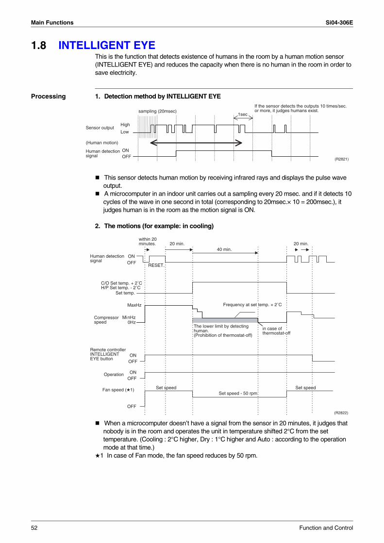
Main Functions Si04-306E
1.8 INTELLIGENT EYEThis is the function that detects existence of humans in the room by a human motion sensor (INTELLIGENT EYE) and reduces the capacity when there is no human in the room in order to save electricity.
Processing 1. Detection method by INTELLIGENT EYE
This sensor detects human motion by receiving infrared rays and displays the pulse wave output.A microcomputer in an indoor unit carries out a sampling every 20 msec. and if it detects 10 cycles of the wave in one second in total (corresponding to 20msec.× 10 = 200msec.), it judges human is in the room as the motion signal is ON.
2. The motions (for example: in cooling)
When a microcomputer doesn’t have a signal from the sensor in 20 minutes, it judges that nobody is in the room and operates the unit in temperature shifted 2°C from the set temperature. (Cooling : 2°C higher, Dry : 1°C higher and Auto : according to the operation mode at that time.)
1 In case of Fan mode, the fan speed reduces by 50 rpm.
If the sensor detects the outputs 10 times/sec. or more, it judges humans exist.
1secsampling (20msec)
High
Low
ONOFF
Sensor output
(Human motion)
Human detectionsignal
(R2821)
ONOFF RESET.
C/O Set temp. + 2˚CH/P Set temp. - 2˚C
Human detectionsignal
20 min. 20 min.within 20minutes.
40 min.
MaxHz
MinHz0Hz
Compressorspeed
The lower limit by detectinghuman.(Prohibition of thermostat-off)
ONOFF
ONOFF
Operation
OFF
Fan speed ( 1)Set speed - 50 rpm
Set speed Set speed
in case ofthermostat-off
Frequency at set temp. + 2˚C
Set temp.
(R2822)
Remote controller INTELLIGENT EYE button
52 Function and Control
Si04-306E Main Functions
Since the set temperature is shifted by 2°C higher for 40 minutes, compressor speed becomes low and can realize energy saving operation. But as thermostat is prone to be off by the fact that the set temperature has been shifted, the thermostat-off action is prohibited in 40 minutes so as to prevent this phenomena.After this 40 minutes, the prohibition of the thermostat-off is cancelled and it can realize the conditions to conduct thermostat-off depending on the room temperature. In or after this 40 minutes, if the sensor detects human motion detection signal, it let the set temperature and the fan speed return to the original set point, keeping a normal operation.
Others The dry operation can’t command the setting temperature with a remote controller, but internally the set temperature is shifted by 1°C.
Function and Control 53
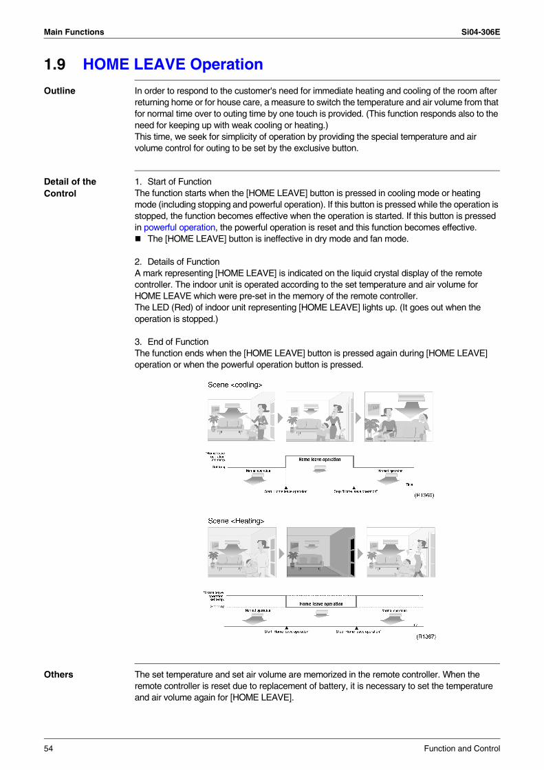
Main Functions Si04-306E
1.9 HOME LEAVE Operation
Outline In order to respond to the customer's need for immediate heating and cooling of the room after returning home or for house care, a measure to switch the temperature and air volume from that for normal time over to outing time by one touch is provided. (This function responds also to the need for keeping up with weak cooling or heating.) This time, we seek for simplicity of operation by providing the special temperature and air volume control for outing to be set by the exclusive button.
Detail of the Control
1. Start of FunctionThe function starts when the [HOME LEAVE] button is pressed in cooling mode or heating mode (including stopping and powerful operation). If this button is pressed while the operation is stopped, the function becomes effective when the operation is started. If this button is pressed in powerful operation, the powerful operation is reset and this function becomes effective.
The [HOME LEAVE] button is ineffective in dry mode and fan mode.
2. Details of FunctionA mark representing [HOME LEAVE] is indicated on the liquid crystal display of the remote controller. The indoor unit is operated according to the set temperature and air volume for HOME LEAVE which were pre-set in the memory of the remote controller.The LED (Red) of indoor unit representing [HOME LEAVE] lights up. (It goes out when the operation is stopped.)
3. End of FunctionThe function ends when the [HOME LEAVE] button is pressed again during [HOME LEAVE] operation or when the powerful operation button is pressed.
Others The set temperature and set air volume are memorized in the remote controller. When the remote controller is reset due to replacement of battery, it is necessary to set the temperature and air volume again for [HOME LEAVE].
54 Function and Control
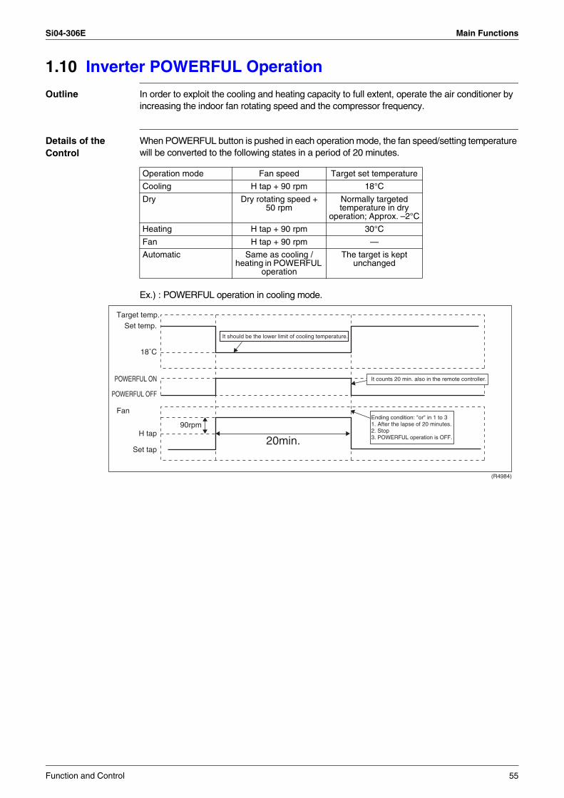
Si04-306E Main Functions
1.10 Inverter POWERFUL Operation
Outline In order to exploit the cooling and heating capacity to full extent, operate the air conditioner by increasing the indoor fan rotating speed and the compressor frequency.
Details of the Control
When POWERFUL button is pushed in each operation mode, the fan speed/setting temperature will be converted to the following states in a period of 20 minutes.
Ex.) : POWERFUL operation in cooling mode.
Operation mode Fan speed Target set temperature
Cooling H tap + 90 rpm 18°C
Dry Dry rotating speed + 50 rpm
Normally targeted temperature in dry
operation; Approx. –2°C
Heating H tap + 90 rpm 30°C
Fan H tap + 90 rpm —
Automatic Same as cooling /heating in POWERFUL
operation
The target is kept unchanged
(R4984)
Target temp.
Fan
90rpm
Set temp.
18˚C
POWERFUL ON
POWERFUL OFF
H tap
Set tap
It should be the lower limit of cooling temperature.
It counts 20 min. also in the remote controller.
Ending condition: "or" in 1 to 31. After the lapse of 20 minutes.2. Stop3. POWERFUL operation is OFF.20min.
Function and Control 55
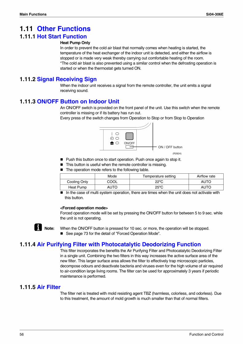
Main Functions Si04-306E
1.11 Other Functions1.11.1 Hot Start Function
Heat Pump OnlyIn order to prevent the cold air blast that normally comes when heating is started, the temperature of the heat exchanger of the indoor unit is detected, and either the airflow is stopped or is made very weak thereby carrying out comfortable heating of the room.*The cold air blast is also prevented using a similar control when the defrosting operation is started or when the thermostat gets turned ON.
1.11.2 Signal Receiving SignWhen the indoor unit receives a signal from the remote controller, the unit emits a signal receiving sound.
1.11.3 ON/OFF Button on Indoor UnitAn ON/OFF switch is provided on the front panel of the unit. Use this switch when the remote controller is missing or if its battery has run out. Every press of the switch changes from Operation to Stop or from Stop to Operation
Push this button once to start operation. Push once again to stop it.This button is useful when the remote controller is missing.The operation mode refers to the following table.
In the case of multi system operation, there are times when the unit does not activate with this button.
<Forced operation mode>Forced operation mode will be set by pressing the ON/OFF button for between 5 to 9 sec. while the unit is not operating.
Note: When the ON/OFF button is pressed for 10 sec. or more, the operation will be stopped.See page 73 for the detail of "Forced Operation Mode".
1.11.4 Air Purifying Filter with Photocatalytic Deodorizing FunctionThis filter incorporates the benefits the Air Purifying Filter and Photocatalytic Deodorizing Filter in a single unit. Combining the two filters in this way increases the active surface area of the new filter. This larger surface area allows the filter to effectively trap microscopic particles, decompose odours and deactivate bacteria and viruses even for the high volume of air required to air-condition large living rooms. The filter can be used for approximately 3 years if periodic maintenance is performed.
1.11.5 Air FilterThe filter net is treated with mold resisting agent TBZ (harmless, colorless, and odorless). Due to this treatment, the amount of mold growth is much smaller than that of normal filters.
ON / OFF button
(R2824)
Mode Temperature setting Airflow rate
Cooling Only COOL 22ºC AUTO
Heat Pump AUTO 25ºC AUTO
56 Function and Control
Si04-306E Main Functions
1.11.6 Self-Diagnosis Digital DisplayThe microcomputer continuously monitors main operating conditions of the indoor unit, outdoor unit and the entire system. When an abnormality occur, the LCD remote controller displays error code. These indications allow prompt maintenance operations.
1.11.7 Auto-restart FunctionEven if a power failure (including one for just a moment) occurs during the operation, the operation restarts in the condition before power failure automatically when power is restored.(Note) It takes 3 minutes to restart the operation because the 3-minute standby function is activated.
Function and Control 57
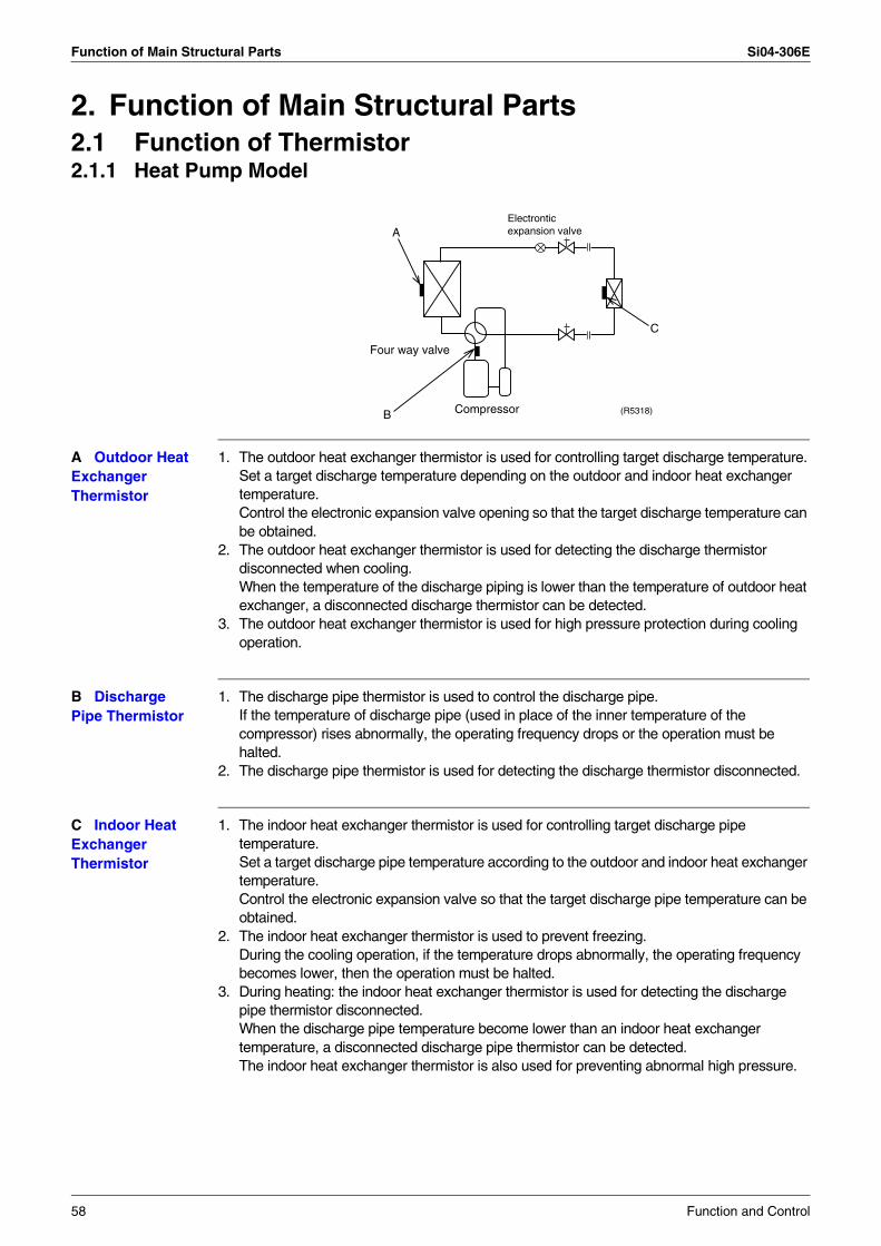
Function of Main Structural Parts Si04-306E
2. Function of Main Structural Parts2.1 Function of Thermistor2.1.1 Heat Pump Model
A Outdoor Heat Exchanger Thermistor
1. The outdoor heat exchanger thermistor is used for controlling target discharge temperature.Set a target discharge temperature depending on the outdoor and indoor heat exchanger temperature.Control the electronic expansion valve opening so that the target discharge temperature can be obtained.
2. The outdoor heat exchanger thermistor is used for detecting the discharge thermistor disconnected when cooling.When the temperature of the discharge piping is lower than the temperature of outdoor heat exchanger, a disconnected discharge thermistor can be detected.
3. The outdoor heat exchanger thermistor is used for high pressure protection during cooling operation.
B Discharge Pipe Thermistor
1. The discharge pipe thermistor is used to control the discharge pipe.If the temperature of discharge pipe (used in place of the inner temperature of the compressor) rises abnormally, the operating frequency drops or the operation must be halted.
2. The discharge pipe thermistor is used for detecting the discharge thermistor disconnected.
C Indoor Heat Exchanger Thermistor
1. The indoor heat exchanger thermistor is used for controlling target discharge pipe temperature.Set a target discharge pipe temperature according to the outdoor and indoor heat exchanger temperature.Control the electronic expansion valve so that the target discharge pipe temperature can be obtained.
2. The indoor heat exchanger thermistor is used to prevent freezing.During the cooling operation, if the temperature drops abnormally, the operating frequency becomes lower, then the operation must be halted.
3. During heating: the indoor heat exchanger thermistor is used for detecting the discharge pipe thermistor disconnected.When the discharge pipe temperature become lower than an indoor heat exchanger temperature, a disconnected discharge pipe thermistor can be detected.The indoor heat exchanger thermistor is also used for preventing abnormal high pressure.
Four way valve
Compressor (R5318)
A
C
B
Electronticexpansion valve
58 Function and Control

Si04-306E Function of Main Structural Parts
2.1.2 Cooling Only Model
A Outdoor Heat Exchanger Thermistor
1. The outdoor heat exchanger thermistor is used for controlling target discharge temperature.Set a target discharge temperature depending on the outdoor and indoor heat exchanger temperature.Control the electronic expansion valve opening so that the target discharge temperature can be obtained.
2. When cooling: an outdoor heat exchanger thermistor is used for detecting the discharge thermistor disconnected.When the temperature of the discharge piping is lower than the temperature of outdoor heat exchanger, a disconnected discharge thermistor can be detected.
3. The outdoor heat exchanger thermistor is used for high pressure protection during cooling operation.
B Discharge Pipe Thermistor
1. The discharge pipe thermistor is used to control the discharge pipe.If the temperature of discharge pipe (used in place of the inner temperature of the compressor) rises abnormally, the operating frequency drops or the operation must be halted.
2. The discharge pipe thermistor is used for detecting the discharge thermistor disconnected.
C Indoor Heat Exchanger Thermistor
1. The indoor heat exchanger thermistor is used for controlling target discharge pipe temperature.Set a target discharge pipe temperature according to the outdoor and indoor heat exchanger temperature.Control the electronic expansion valve opening so that the target discharge pipe temperature can be obtained.
2. The indoor heat exchanger thermistor is used to prevent freezing.During the cooling operation, if the temperature drops abnormally, the operating frequency becomes lower, then the operation must be halted.
A
C
BCompressor
(R2828)
Electronticexpansion valve
Function and Control 59
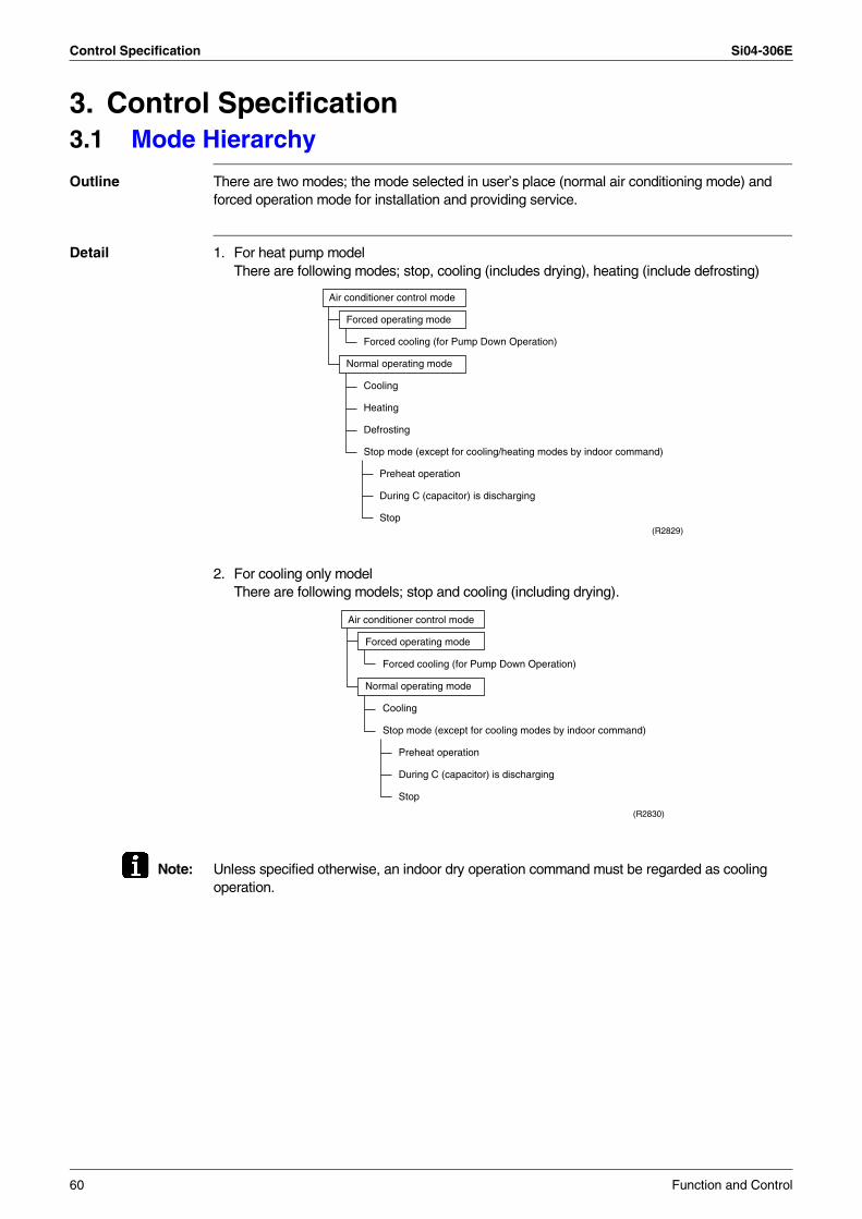
Control Specification Si04-306E
3. Control Specification3.1 Mode Hierarchy
Outline There are two modes; the mode selected in user’s place (normal air conditioning mode) and forced operation mode for installation and providing service.
Detail 1. For heat pump modelThere are following modes; stop, cooling (includes drying), heating (include defrosting)
2. For cooling only model There are following models; stop and cooling (including drying).
Note: Unless specified otherwise, an indoor dry operation command must be regarded as cooling operation.
Air conditioner control mode
Forced operating mode
Forced cooling (for Pump Down Operation)
Normal operating mode
Cooling
Heating
Defrosting
Stop mode (except for cooling/heating modes by indoor command)
Preheat operation
During C (capacitor) is discharging
Stop(R2829)
Air conditioner control mode
Forced operating mode
Forced cooling (for Pump Down Operation)
Normal operating mode
Cooling
Stop mode (except for cooling modes by indoor command)
Preheat operation
During C (capacitor) is discharging
Stop
(R2830)
60 Function and Control
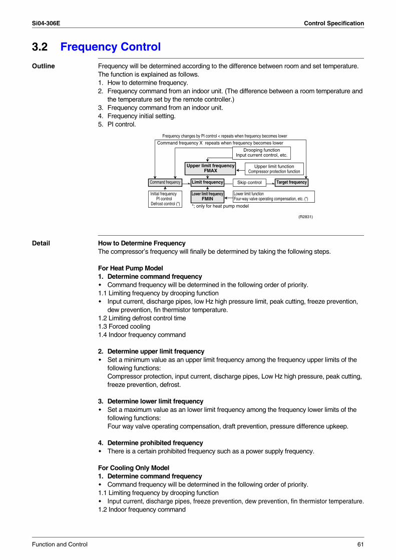
Si04-306E Control Specification
3.2 Frequency Control
Outline Frequency will be determined according to the difference between room and set temperature. The function is explained as follows.1. How to determine frequency.2. Frequency command from an indoor unit. (The difference between a room temperature and
the temperature set by the remote controller.)3. Frequency command from an indoor unit.4. Frequency initial setting.5. PI control.
Detail How to Determine FrequencyThe compressor’s frequency will finally be determined by taking the following steps.
For Heat Pump Model1. Determine command frequency
Command frequency will be determined in the following order of priority.1.1 Limiting frequency by drooping function
Input current, discharge pipes, low Hz high pressure limit, peak cutting, freeze prevention, dew prevention, fin thermistor temperature.
1.2 Limiting defrost control time1.3 Forced cooling1.4 Indoor frequency command
2. Determine upper limit frequencySet a minimum value as an upper limit frequency among the frequency upper limits of the following functions: Compressor protection, input current, discharge pipes, Low Hz high pressure, peak cutting, freeze prevention, defrost.
3. Determine lower limit frequencySet a maximum value as an lower limit frequency among the frequency lower limits of the following functions: Four way valve operating compensation, draft prevention, pressure difference upkeep.
4. Determine prohibited frequencyThere is a certain prohibited frequency such as a power supply frequency.
For Cooling Only Model1. Determine command frequency
Command frequency will be determined in the following order of priority.1.1 Limiting frequency by drooping function
Input current, discharge pipes, freeze prevention, dew prevention, fin thermistor temperature.1.2 Indoor frequency command
Command frequency Limit frequency Skip control
Upper limit functionCompressor protection function
Lower limit functionFour-way valve operating compensation, etc. (*)
Initial frequency PI control
Defrost control (*)
Drooping functionInput current control, etc.
Upper limit frequencyFMAX
Lower limit frequencyFMIN
Target frequency
Command frequency X repeats when frequency becomes lower
Frequency changes by PI control < repeats when frequency becomes lower
*; only for heat pump model
(R2831)
Function and Control 61
Control Specification Si04-306E
2. Determine upper limit frequencySet a minimum value as an upper limit frequency among the frequency upper limits of the following functions: Compressor protection, input current, discharge pipes, freeze prevention, dew prevention, fin thermistor temperature.
3. Determine lower limit frequencySet a maximum value as an lower limit frequency among the frequency lower limits of the following functions: Pressure difference upkeep.
4. Determine prohibited frequencyThere is a certain prohibited frequency such as a power supply frequency.
Indoor Frequency Command (∆D signal)The difference between a room temperature and the temperature set by the remote controller will be taken as the “∆D signal” and is used for frequency command.
∗Th OFF = Thermostat OFF
Frequency Initial Setting<Outline>When starting the compressor, or when conditions are varied due to the change of the room, the frequency must be initialized according to the total of a maximum ∆D value of the indoor unit and the Q value of the indoor unit.Q value: Indoor unit output determined from indoor unit volume, airflow rate and other factors.
PI Control (Determine Frequency Up/Down by ∆D Signal)1. P control
Calculate ∆D value in each sampling time (20 seconds), and adjust the frequency according to its difference from the frequency previously calculated.
2. I controlIf the operating frequency is not change more than a certain fixed time, adjust the frequency up and down according to the ∆D value, obtaining the fixed ∆D value.When the ∆D value is small...lower the frequency.When the ∆D value is large...increase the frequency.
3. Limit of frequency variation widthWhen the difference between input current and input current drooping value is less than 1.5 A, the frequency increase width must be limited.
4. Frequency management when other controls are functioningWhen frequency is drooping; Frequency management is carried out only when the frequency droops.For limiting lower limit Frequency management is carried out only when the frequency rises.
5. Upper and lower limit of frequency by PI control The frequency upper and lower limits are set depending on indoor unit.When low noise commands come from the indoor unit or when outdoor unit low noise or quiet commands come from indoor unit, the upper limit frequency must be lowered than the usual setting.
Temperature difference
∆D signal
Temperature difference
∆D signal
Temperature difference
∆D signal
Temperature difference
∆D signal
0 ∗Th OFF
2.0 4 4.0 8 6.0 C
0.5 1 2.5 5 4.5 9 6.5 D
1.0 2 3.0 6 5.0 A 7.0 E
1.5 3 3.5 7 5.5 B 7.5 F
62 Function and Control
Si04-306E Control Specification
3.3 Controls at Mode Changing / Start-up3.3.1 Preheating Operation
Outline Operate the inverter in the open phase operation with the conditions including the preheating command from the indoor, the outdoor air temperature and discharge pipe temperature.
Detail Preheating ON ConditionWhen outdoor air temperature is below 10.5ºC and discharge pipe temperature is below 10.5ºC, inverter in open phase operation starts.(The power consumption of compressor during preheat operation is 35 W.)
OFF ConditionWhen outdoor air temperature is higher than 12ºC or discharge pipe temperature is higher than 12ºC, inverter in open phase operation stops.
3.3.2 Four Way Valve Switching
Outline Heat Pump OnlyDuring the heating operation current must be conducted and during cooling and defrosting current must not be conducted. In order to eliminate the switching sound (as the four way valve coil switches from ON to OFF) when the heating is stopped, the delay switch of the four way valve must be carried out after the operation stopped.
Detail The OFF delay of four way valve Energize the coil for 150 sec after unit operation is stopped.
3.3.3 Four Way Valve Operation Compensation
Outline Heat Pump OnlyAt the beginning of the operation as the four way valve is switched, acquire the differential pressure required for activating the four way valve by having output the operating frequency, which is more than a certain fixed frequency, for a certain fixed time.
Detail Starting Conditions1. When starting compressor for heating.2. When the operating mode changes from the previous time.3. When starting compressor for starting defrosting or resetting.4. When starting compressor for the first time after the reset with the power is ON.
Set the lower limit frequency to 55 (model by model) Hz for 70 seconds with any conditions 1 through 4 above.
3.3.4 3-Minute StandbyProhibit to turn ON the compressor for 3 minutes after turning it off.(Except when defrosting. (Only for Heat Pump Model).)
3.3.5 Compressor Protection FunctionWhen turning the compressor from OFF to ON, the upper limit of frequency must be set as follows. (The function must not be used when defrosting (only for heat pump model).)
FCG 3
FCG 2
FCG 1
2YC63
85
70
40
Others
85
70
55
Function and Control 63
Control Specification Si04-306E
3.4 Discharge Pipe Temperature Control
Outline The discharge pipe temperature is used as the compressor's internal temperature. If the discharge pipe temperature rises above a certain level, the operating frequency upper limit is set to keep this temperature from going up further.
Detail Divide the Zone
Management within the Zones
3.5 Input Current Control
Outline Detect an input current by the CT during the compressor is running, and set the frequency upper limit from such input current.In case of heat pump model, this control is the upper limit control function of the frequency which takes priority of the lower limit of four way valve activating compensation.
Detail The frequency control will be made within the following zones.
When a “stop current” continues for 2.5 seconds after rushing on the stop zone, the compressor operation stops.If a “drooping current” is continues for 1.0 second after rushing on the drooping zone, the frequency will be 2 Hz drooping.Repeating the above drooping continues until the current rushes on the drooping zone without change.In the keep zone, the frequency limit will remain.In the return / reset zone, the frequency limit will be cancelled.Limitation of current drooping and stop value according to the outdoor air temperature1. In case the operation mode is cooling
The current droops when outdoor air temperature becomes higher than a certain level (model by model).
2. In case the operation mode is heating (only for heat pump model)The current droops when outdoor air temperature becomes higher than a certain level (model by model).
Zone Control contents
Stop zone When the temperature reaches the stop zone, stop the compressor and correct abnormality.
Drooping zone Start the timer, and the frequency will be drooping.
Keep zone Keep the upper limit of frequency.
Return / Reset zone Cancel the upper limit of frequency.
A
B
C
D
(R8517)
ABCD
120111109107
Keep
64 Function and Control

Si04-306E Control Specification
3.6 Freeze-up Protection Control
Outline During cooling operation, the signals being sent from the indoor unit allow the operating frequency limitation and then prevent freezing of the indoor heat exchanger. (The signal from the indoor unit must be divided into the zones as the followings.
Detail Conditions for Start ControllingJudge the controlling start with the indoor heat exchanger temperature after 2 sec from operation start.Control in Each Zone
3.7 Heating Peak-cut Control
Outline Heat Pump OnlyDuring heating operation, the signals being sent from the indoor unit allow the operating frequency limitation and prevent abnormal high pressure. (The signal from the indoor unit must be divided as follows.)
Detail Conditions for Start ControllingJudge the controlling start with the indoor heat exchanger temperature after 2 min from operation start.Control in Each ZoneThe heat exchange intermediate temperature of indoor unit controls the following.
Function and Control 65
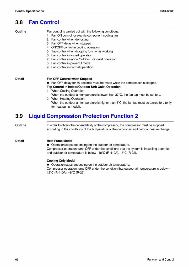
Control Specification Si04-306E
3.8 Fan Control
Outline Fan control is carried out with the following conditions.1. Fan ON control for electric component cooling fan2. Fan control when defrosting3. Fan OFF delay when stopped 4. ON/OFF control in cooling operation5. Tap control when drooping function is working 6. Fan control in forced operation 7. Fan control in indoor/outdoor unit quiet operation8. Fan control in powerful mode9. Fan control in normal operation
Detail Fan OFF Control when StoppedFan OFF delay for 60 seconds must be made when the compressor is stopped.
Tap Control in Indoor/Outdoor Unit Quiet Operation1. When Cooling Operation
When the outdoor air temperature is lower than 37°C, the fan tap must be set to L.2. When Heating Operation
When the outdoor air temperature is higher than 4°C, the fan tap must be turned to L (only for heat pump model).
3.9 Liquid Compression Protection Function 2
Outline In order to obtain the dependability of the compressor, the compressor must be stopped according to the conditions of the temperature of the outdoor air and outdoor heat exchanger.
Detail Heat Pump ModelOperation stops depending on the outdoor air temperature.
Compressor operation turns OFF under the conditions that the system is in cooling operation and outdoor air temperature is below –10°C (R-410A), –5°C (R-22).
Cooling Only ModelOperation stops depending on the outdoor air temperature.
Compressor operation turns OFF under the condition that outdoor air temperature is below –12°C (R-410A), –5°C (R-22).
66 Function and Control
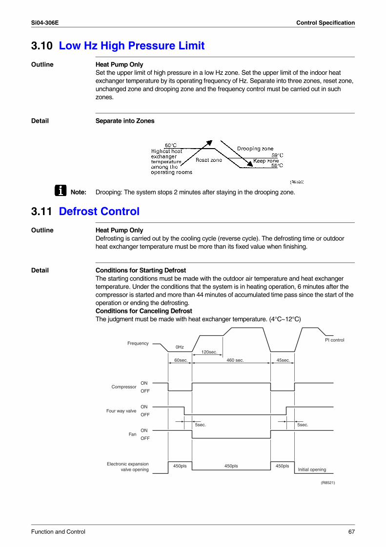
Si04-306E Control Specification
3.10 Low Hz High Pressure Limit
Outline Heat Pump OnlySet the upper limit of high pressure in a low Hz zone. Set the upper limit of the indoor heat exchanger temperature by its operating frequency of Hz. Separate into three zones, reset zone, unchanged zone and drooping zone and the frequency control must be carried out in such zones.
Detail Separate into Zones
Note: Drooping: The system stops 2 minutes after staying in the drooping zone.
3.11 Defrost Control
Outline Heat Pump OnlyDefrosting is carried out by the cooling cycle (reverse cycle). The defrosting time or outdoor heat exchanger temperature must be more than its fixed value when finishing.
Detail Conditions for Starting DefrostThe starting conditions must be made with the outdoor air temperature and heat exchanger temperature. Under the conditions that the system is in heating operation, 6 minutes after the compressor is started and more than 44 minutes of accumulated time pass since the start of the operation or ending the defrosting.Conditions for Canceling DefrostThe judgment must be made with heat exchanger temperature. (4°C~12°C)
Frequency
Compressor
Four way valve
Fan
Electronic expansionvalve opening
ON
OFF
ON
OFF
ON
OFF
0Hz
5sec.
450pls450pls450plsInitial opening
PI control
5sec.
45sec.60sec. 460 sec.
120sec.
(R8521)
Function and Control 67
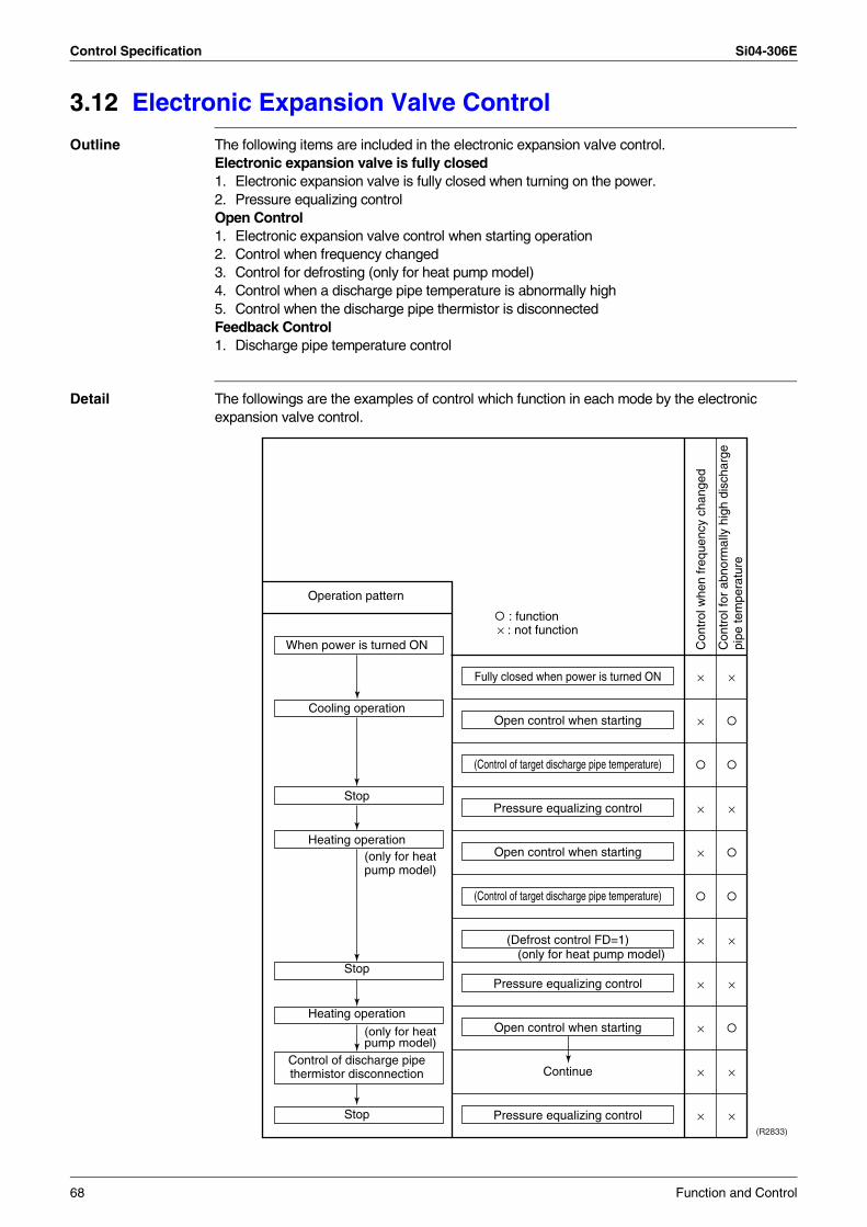
Control Specification Si04-306E
3.12 Electronic Expansion Valve Control
Outline The following items are included in the electronic expansion valve control.Electronic expansion valve is fully closed1. Electronic expansion valve is fully closed when turning on the power.2. Pressure equalizing controlOpen Control1. Electronic expansion valve control when starting operation2. Control when frequency changed3. Control for defrosting (only for heat pump model)4. Control when a discharge pipe temperature is abnormally high5. Control when the discharge pipe thermistor is disconnectedFeedback Control1. Discharge pipe temperature control
Detail The followings are the examples of control which function in each mode by the electronic expansion valve control.
(R2833)
×
×
×
×
×
×
×
×
×
×
×
×
×
×
×
Fully closed when power is turned ON
Open control when starting
(Control of target discharge pipe temperature)
Pressure equalizing control
Open control when starting
(Control of target discharge pipe temperature)
(Defrost control FD=1)
Pressure equalizing control
Open control when starting
Continue
Pressure equalizing control
Con
trol
whe
n fr
eque
ncy
chan
ged
Con
trol
for
abno
rmal
ly h
igh
disc
harg
e pi
pe te
mpe
ratu
re
When power is turned ON
Cooling operation
Stop
Heating operation
Stop
Heating operation
Control of discharge pipe thermistor disconnection
Stop
Operation pattern
(only for heat pump model)
(only for heat pump model)
: function × : not function
(only for heat pump model)
68 Function and Control
Si04-306E Control Specification
3.12.1 Fully Closing with Power ONInitialize the electronic expansion valve when turning on the power, set the opening position and develop pressure equalizing.
3.12.2 Pressure Equalization ControlWhen the compressor is stopped, open and close the electronic expansion valve and develop pressure equalization.
3.12.3 Opening Limit
Outline Limit a maximum and minimum opening of the electronic expansion valve.
Detail A maximum electronic expansion valve opening : 450 pulsesA minimum electronic expansion valve opening : 54 pulses
The electronic expansion valve is fully closed in the room where cooling is stopped and is opened with fixed opening during defrosting.
3.12.4 Starting Operation ControlControl the electronic expansion valve opening when the system is starting, and prevent the system to be super heated or moistened.
3.12.5 High Temperature of the Discharge PipeWhen the compressor is operating, if the discharge pipe temperature exceeds a certain value, open the electronic expansion valve and remove the refrigerant to the low pressure side and lower discharge temperature.
3.12.6 Disconnection of the Discharge Pipe Thermistor
Outline Detect a disconnected discharge pipe thermistor by comparing the discharge pipe temperature with the condensation temperature. If any is disconnected, open the electronic expansion valve according to the outdoor air temperature and the operating frequency, and operate for a specified time, and then stop.After 3 minutes of waiting, restart the unit and check if any is disconnected. If any is disconnected stop the system after operating for a specified time. If the disconnection is detected 4 times in succession, then the system will be down.
Detail Detect DisconnectionIf a 630-second timer for open control becomes over, and a 9-minute timer for the compressor operation continuation is not counting time, the following adjustment must be made.1. When the operation mode is cooling
When the discharge pipe temperature is lower than the outdoor heat exchanger temperature, the discharge pipe thermistor disconnection must be ascertained.
2. When the operation mode is heating (only for heat pump model)When the discharge pipe temperature is lower than the max temperature of operating room heat exchanger, the discharge pipe thermistor disconnection must be ascertained.
Adjustment when the thermistor is disconnectedWhen compressor stop repeats specified time, the system should be down.
Function and Control 69
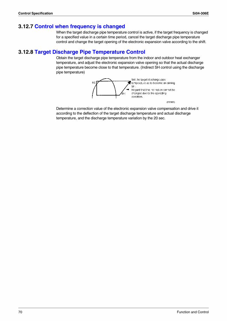
Control Specification Si04-306E
3.12.7 Control when frequency is changedWhen the target discharge pipe temperature control is active, if the target frequency is changed for a specified value in a certain time period, cancel the target discharge pipe temperature control and change the target opening of the electronic expansion valve according to the shift.
3.12.8 Target Discharge Pipe Temperature ControlObtain the target discharge pipe temperature from the indoor and outdoor heat exchanger temperature, and adjust the electronic expansion valve opening so that the actual discharge pipe temperature become close to that temperature. (Indirect SH control using the discharge pipe temperature)
Determine a correction value of the electronic expansion valve compensation and drive it according to the deflection of the target discharge temperature and actual discharge temperature, and the discharge temperature variation by the 20 sec.
70 Function and Control
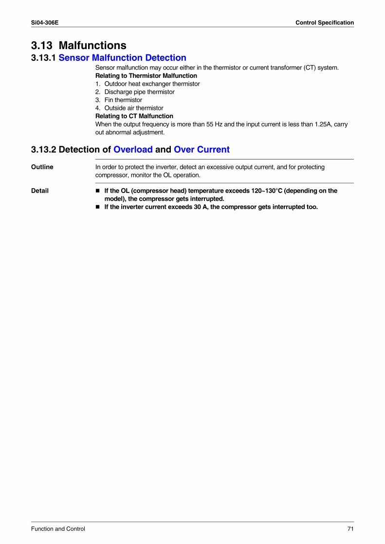
Si04-306E Control Specification
3.13 Malfunctions3.13.1 Sensor Malfunction Detection
Sensor malfunction may occur either in the thermistor or current transformer (CT) system.Relating to Thermistor Malfunction1. Outdoor heat exchanger thermistor2. Discharge pipe thermistor3. Fin thermistor4. Outside air thermistorRelating to CT MalfunctionWhen the output frequency is more than 55 Hz and the input current is less than 1.25A, carry out abnormal adjustment.
3.13.2 Detection of Overload and Over Current
Outline In order to protect the inverter, detect an excessive output current, and for protecting compressor, monitor the OL operation.
Detail If the OL (compressor head) temperature exceeds 120~130°C (depending on the model), the compressor gets interrupted.If the inverter current exceeds 30 A, the compressor gets interrupted too.
Function and Control 71
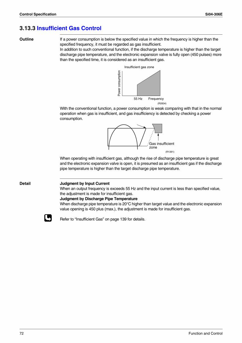
Control Specification Si04-306E
3.13.3 Insufficient Gas Control
Outline If a power consumption is below the specified value in which the frequency is higher than the specified frequency, it must be regarded as gas insufficient.In addition to such conventional function, if the discharge temperature is higher than the target discharge pipe temperature, and the electronic expansion valve is fully open (450 pulses) more than the specified time, it is considered as an insufficient gas.
With the conventional function, a power consumption is weak comparing with that in the normal operation when gas is insufficient, and gas insufficiency is detected by checking a power consumption.
When operating with insufficient gas, although the rise of discharge pipe temperature is great and the electronic expansion valve is open, it is presumed as an insufficient gas if the discharge pipe temperature is higher than the target discharge pipe temperature.
Detail Judgment by Input CurrentWhen an output frequency is exceeds 55 Hz and the input current is less than specified value, the adjustment is made for insufficient gas.Judgment by Discharge Pipe TemperatureWhen discharge pipe temperature is 20°C higher than target value and the electronic expansion value opening is 450 plus (max.), the adjustment is made for insufficient gas.
Refer to “Insufficient Gas” on page 139 for details.
Frequency
Pow
er c
onsu
mpt
ion
Insufficient gas zone
55 Hz(R2834)
Gas insufficientzone
(R1391)
72 Function and Control
Si04-306E Control Specification
3.14 Forced Operation Mode
Outline Forced operating mode includes only forced cooling.
Detail Forced Cooling
3.15 Additional Function3.15.1 POWERFUL Operation Mode
Compressor operating frequency is increased to PI Max. (Max. Hz of operating room) and outdoor unit airflow rate is increased.
3.15.2 Voltage Detection Function Power supply voltage is detected each time equipment operation starts.
Item Forced Cooling
Forced operation allowing conditions
1) The outdoor unit is not abnormal and not in the 3-minute standby mode.
2) The operating mode of the outdoor unit is the stop mode.
3) The forced operation is ON. The forced operation is allowed when the above “and” conditions are met.
Starting/adjustment If the forced operation switch is pressed as the above conditions are met.
1) Command frequency
66 Hz
2) Electronic expansion valve opening
Depending on the capacity of the indoor unit.
3) Outdoor unit adjustment
Compressor is in operation
4) Indoor unit adjustment
Transmit the command of forced draft to the indoor unit.
End 1) When the forced operation switch is pressed again.
2) The operation is to end automatically after 15 min.
Others The protect functions are prior to all others in the forced operation.
Function and Control 73
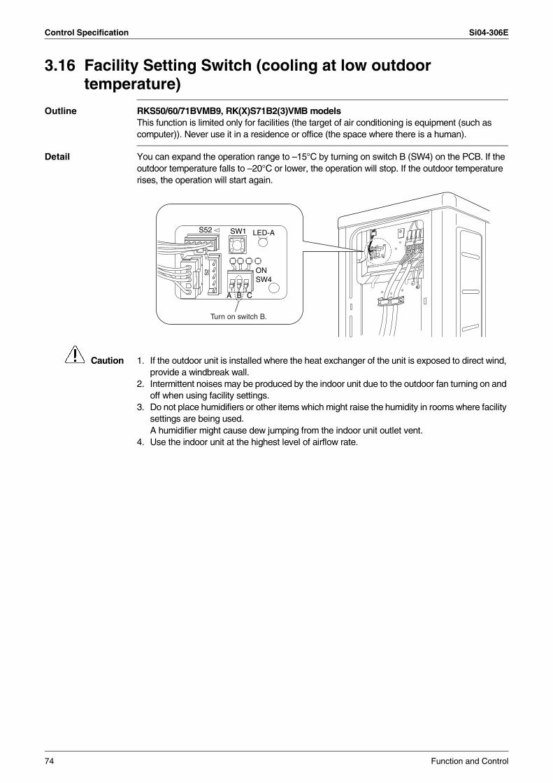
Control Specification Si04-306E
3.16 Facility Setting Switch (cooling at low outdoor temperature)
Outline RKS50/60/71BVMB9, RK(X)S71B2(3)VMB modelsThis function is limited only for facilities (the target of air conditioning is equipment (such as computer)). Never use it in a residence or office (the space where there is a human).
Detail You can expand the operation range to –15°C by turning on switch B (SW4) on the PCB. If the outdoor temperature falls to –20°C or lower, the operation will stop. If the outdoor temperature rises, the operation will start again.
Caution 1. If the outdoor unit is installed where the heat exchanger of the unit is exposed to direct wind, provide a windbreak wall.
2. Intermittent noises may be produced by the indoor unit due to the outdoor fan turning on and off when using facility settings.
3. Do not place humidifiers or other items which might raise the humidity in rooms where facility settings are being used.A humidifier might cause dew jumping from the indoor unit outlet vent.
4. Use the indoor unit at the highest level of airflow rate.
A B C
ONSW4
LED-AS52 SW1
S2
1A1 2 3
Turn on switch B.
74 Function and Control
Si04-306E
Operation Manual 75
Part 5Operation Manual
1. System Configuration............................................................................762. Instruction..............................................................................................77
2.1 Safety Precautions .................................................................................772.2 Names of Parts.......................................................................................792.3 Preparation Before Operation ................................................................822.4 AUTO · DRY · COOL · HEAT · FAN Operation ......................................852.5 Adjusting the Airflow Direction................................................................872.6 POWERFUL Operation ..........................................................................892.7 OUTDOOR UNIT QUIET Operation.......................................................902.8 HOME LEAVE Operation .......................................................................912.9 INTELLIGENT EYE Operation ...............................................................932.10 TIMER Operation ...................................................................................952.11 Care and Cleaning .................................................................................972.12 Troubleshooting....................................................................................100
System Configuration Si04-306E
1. System ConfigurationAfter the installation and test operation of the room air conditioner have been completed, it should be operated and handled as described below. Every user would like to know the correct method of operation of the room air conditioner, to check if it is capable of cooling (or heating) well, and to know a clever method of using it.In order to meet this expectation of the users, giving sufficient explanations taking enough time can be said to reduce about 80% of the requests for servicing. However good the installation work is and however good the functions are, the customer may blame either the room air conditioner or its installation work because of improper handling. The installation work and handing over of the unit can only be considered to have been completed when its handling has been explained to the user without using technical terms but giving full knowledge of the equipment.
76 Operation Manual
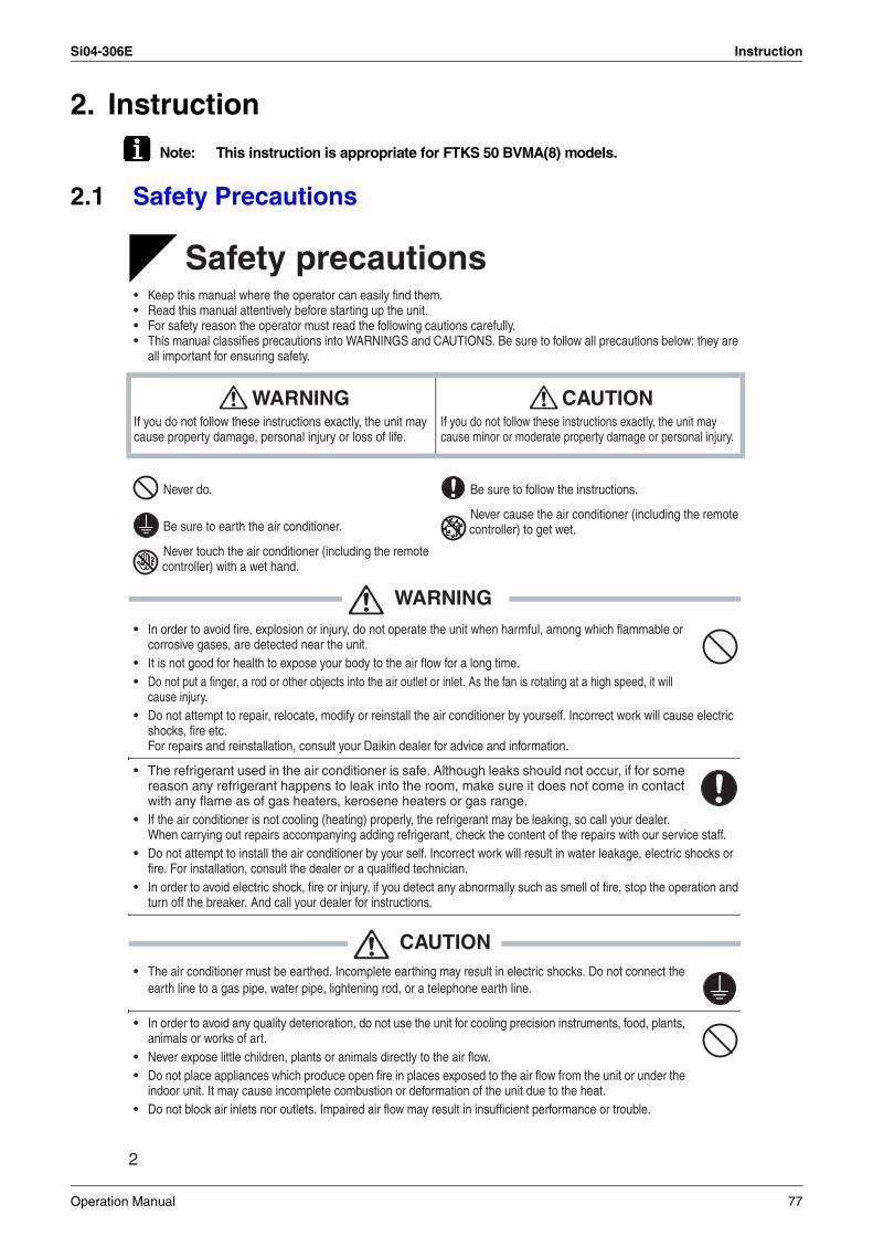
Si04-306E Instruction
2. InstructionNote: This instruction is appropriate for FTKS 50 BVMA(8) models.
2.1 Safety Precautions
2
READ BEFORE OPERATION
Safety precautions• Keep this manual where the operator can easily find them.• Read this manual attentively before starting up the unit.• For safety reason the operator must read the following cautions carefully.• This manual classifies precautions into WARNINGS and CAUTIONS. Be sure to follow all precautions below: they are
all important for ensuring safety.
WARNING• In order to avoid fire, explosion or injury, do not operate the unit when harmful, among which flammable or
corrosive gases, are detected near the unit.• It is not good for health to expose your body to the air flow for a long time.• Do not put a finger, a rod or other objects into the air outlet or inlet. As the fan is rotating at a high speed, it will
cause injury.• Do not attempt to repair, relocate, modify or reinstall the air conditioner by yourself. Incorrect work will cause electric
shocks, fire etc. For repairs and reinstallation, consult your Daikin dealer for advice and information.
• The refrigerant used in the air conditioner is safe. Although leaks should not occur, if for some reason any refrigerant happens to leak into the room, make sure it does not come in contact with any flame as of gas heaters, kerosene heaters or gas range.
• If the air conditioner is not cooling (heating) properly, the refrigerant may be leaking, so call your dealer.When carrying out repairs accompanying adding refrigerant, check the content of the repairs with our service staff.
• Do not attempt to install the air conditioner by your self. Incorrect work will result in water leakage, electric shocks or fire. For installation, consult the dealer or a qualified technician.
• In order to avoid electric shock, fire or injury, if you detect any abnormally such as smell of fire, stop the operation and turn off the breaker. And call your dealer for instructions.
CAUTION• The air conditioner must be earthed. Incomplete earthing may result in electric shocks. Do not connect the
earth line to a gas pipe, water pipe, lightening rod, or a telephone earth line.
• In order to avoid any quality deterioration, do not use the unit for cooling precision instruments, food, plants, animals or works of art.
• Never expose little children, plants or animals directly to the air flow.• Do not place appliances which produce open fire in places exposed to the air flow from the unit or under the
indoor unit. It may cause incomplete combustion or deformation of the unit due to the heat.• Do not block air inlets nor outlets. Impaired air flow may result in insufficient performance or trouble.
WARNINGIf you do not follow these instructions exactly, the unit may cause property damage, personal injury or loss of life.
CAUTIONIf you do not follow these instructions exactly, the unit may cause minor or moderate property damage or personal injury.
Never do. Be sure to follow the instructions.
Be sure to earth the air conditioner.Never cause the air conditioner (including the remote controller) to get wet.
Never touch the air conditioner (including the remote controller) with a wet hand.
Operation Manual 77
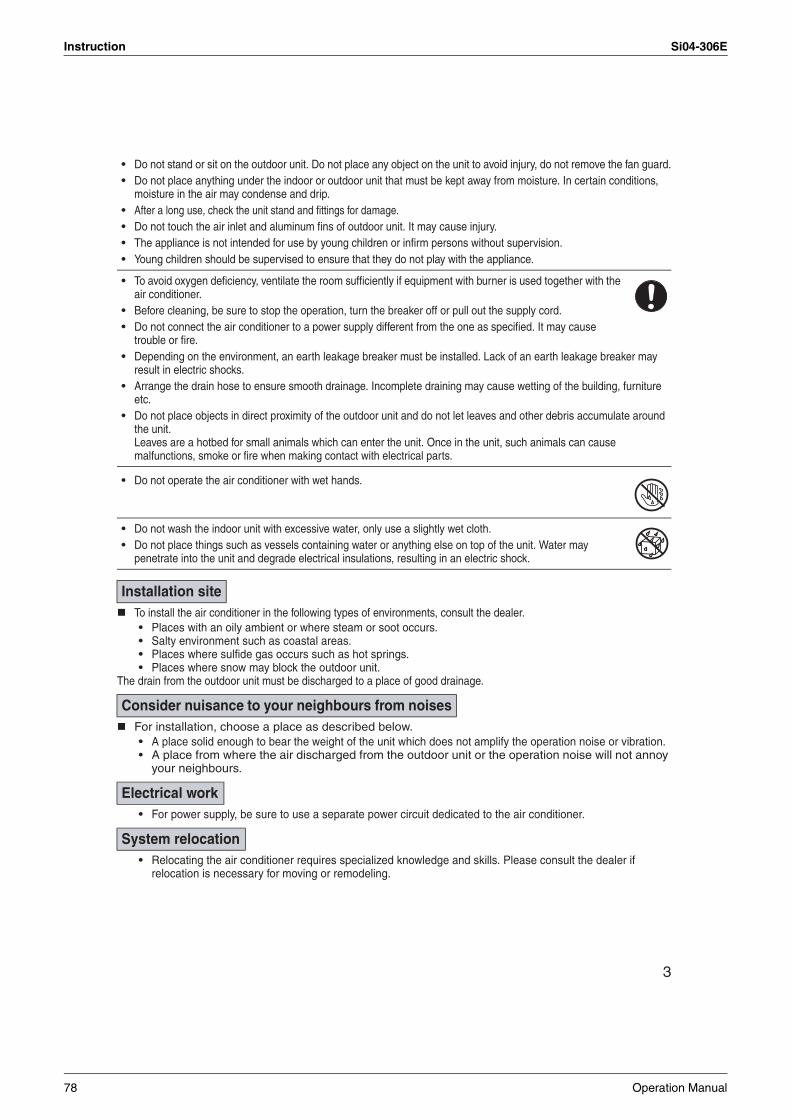
Instruction Si04-306E
3
• Do not stand or sit on the outdoor unit. Do not place any object on the unit to avoid injury, do not remove the fan guard.• Do not place anything under the indoor or outdoor unit that must be kept away from moisture. In certain conditions,
moisture in the air may condense and drip.• After a long use, check the unit stand and fittings for damage.• Do not touch the air inlet and aluminum fins of outdoor unit. It may cause injury.• The appliance is not intended for use by young children or infirm persons without supervision.• Young children should be supervised to ensure that they do not play with the appliance.
• To avoid oxygen deficiency, ventilate the room sufficiently if equipment with burner is used together with the air conditioner.
• Before cleaning, be sure to stop the operation, turn the breaker off or pull out the supply cord.• Do not connect the air conditioner to a power supply different from the one as specified. It may cause
trouble or fire.• Depending on the environment, an earth leakage breaker must be installed. Lack of an earth leakage breaker may
result in electric shocks.• Arrange the drain hose to ensure smooth drainage. Incomplete draining may cause wetting of the building, furniture
etc.• Do not place objects in direct proximity of the outdoor unit and do not let leaves and other debris accumulate around
the unit. Leaves are a hotbed for small animals which can enter the unit. Once in the unit, such animals can cause malfunctions, smoke or fire when making contact with electrical parts.
• Do not operate the air conditioner with wet hands.
• Do not wash the indoor unit with excessive water, only use a slightly wet cloth.• Do not place things such as vessels containing water or anything else on top of the unit. Water may
penetrate into the unit and degrade electrical insulations, resulting in an electric shock.
To install the air conditioner in the following types of environments, consult the dealer.• Places with an oily ambient or where steam or soot occurs.• Salty environment such as coastal areas.• Places where sulfide gas occurs such as hot springs.• Places where snow may block the outdoor unit.
The drain from the outdoor unit must be discharged to a place of good drainage.
For installation, choose a place as described below.• A place solid enough to bear the weight of the unit which does not amplify the operation noise or vibration.• A place from where the air discharged from the outdoor unit or the operation noise will not annoy
your neighbours.
• For power supply, be sure to use a separate power circuit dedicated to the air conditioner.
• Relocating the air conditioner requires specialized knowledge and skills. Please consult the dealer if relocation is necessary for moving or remodeling.
Installation site
Consider nuisance to your neighbours from noises
Electrical work
System relocation
78 Operation Manual
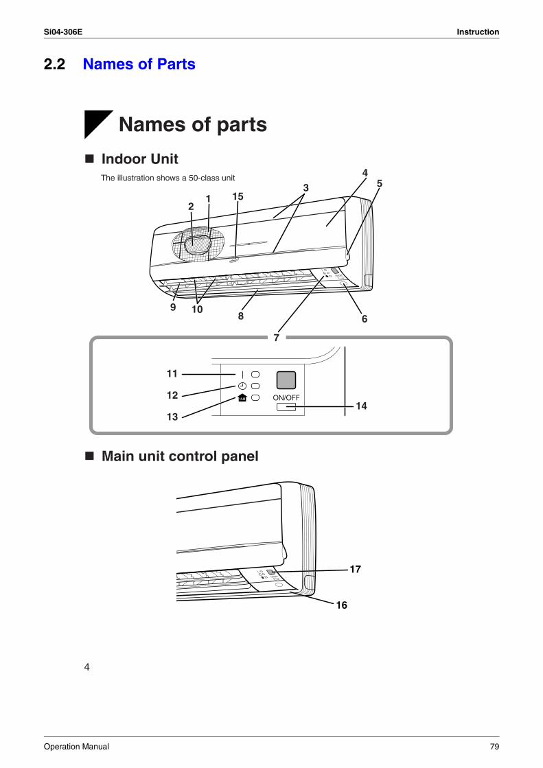
Si04-306E Instruction
2.2 Names of Parts
4
Names of parts
Indoor Unit
Main unit control panel
7
14
11
12
13
43
1512
9 108 6
5The illustration shows a 50-class unit
17
16
Operation Manual 79
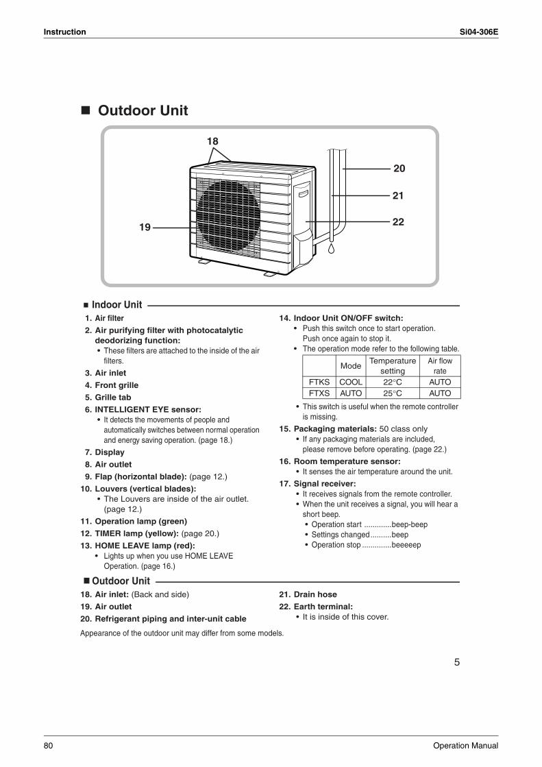
Instruction Si04-306E
5
Outdoor Unit
Indoor Unit1. Air filter
2. Air purifying filter with photocatalytic deodorizing function: • These filters are attached to the inside of the air
filters.
3. Air inlet
4. Front grille
5. Grille tab
6. INTELLIGENT EYE sensor: • It detects the movements of people and
automatically switches between normal operation and energy saving operation. (page 18.)
7. Display
8. Air outlet
9. Flap (horizontal blade): (page 12.)
10. Louvers (vertical blades): • The Louvers are inside of the air outlet.
(page 12.)
11. Operation lamp (green)
12. TIMER lamp (yellow): (page 20.)
13. HOME LEAVE lamp (red):• Lights up when you use HOME LEAVE
Operation. (page 16.)
14. Indoor Unit ON/OFF switch:• Push this switch once to start operation.
Push once again to stop it.• The operation mode refer to the following table.
• This switch is useful when the remote controller is missing.
15. Packaging materials: 50 class only • If any packaging materials are included,
please remove before operating. (page 22.)
16. Room temperature sensor: • It senses the air temperature around the unit.
17. Signal receiver: • It receives signals from the remote controller. • When the unit receives a signal, you will hear a
short beep. • Operation start .............beep-beep • Settings changed..........beep • Operation stop ..............beeeeep
Outdoor Unit18. Air inlet: (Back and side)
19. Air outlet
20. Refrigerant piping and inter-unit cable
21. Drain hose
22. Earth terminal: • It is inside of this cover.
Appearance of the outdoor unit may differ from some models.
20
21
2219
18
ModeTemperature
settingAir flow
rateFTKS COOL 22°C AUTOFTXS AUTO 25°C AUTO
80 Operation Manual
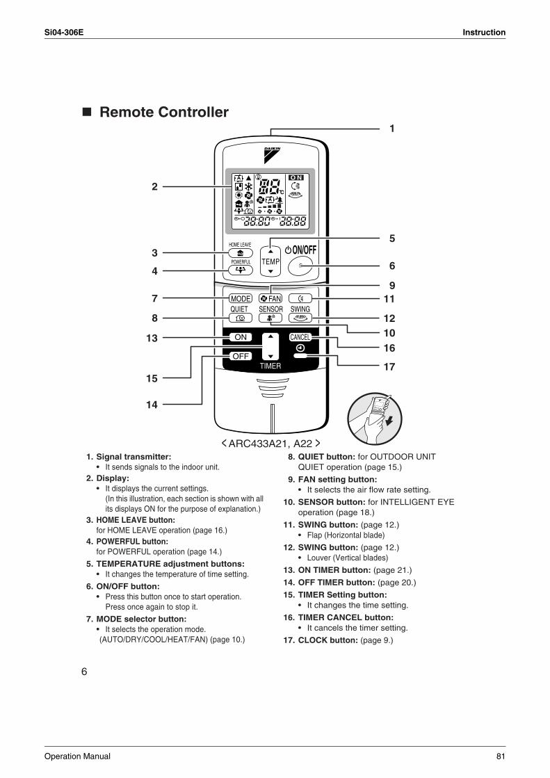
Si04-306E Instruction
6
Remote Controller
1. Signal transmitter:• It sends signals to the indoor unit.
2. Display:• It displays the current settings.
(In this illustration, each section is shown with all its displays ON for the purpose of explanation.)
3. HOME LEAVE button: for HOME LEAVE operation (page 16.)
4. POWERFUL button: for POWERFUL operation (page 14.)
5. TEMPERATURE adjustment buttons:• It changes the temperature of time setting.
6. ON/OFF button:• Press this button once to start operation.
Press once again to stop it.
7. MODE selector button:• It selects the operation mode.(AUTO/DRY/COOL/HEAT/FAN) (page 10.)
8. QUIET button: for OUTDOOR UNIT QUIET operation (page 15.)
9. FAN setting button:• It selects the air flow rate setting.
10. SENSOR button: for INTELLIGENT EYE operation (page 18.)
11. SWING button: (page 12.)• Flap (Horizontal blade)
12. SWING button: (page 12.)• Louver (Vertical blades)
13. ON TIMER button: (page 21.)
14. OFF TIMER button: (page 20.)
15. TIMER Setting button:• It changes the time setting.
16. TIMER CANCEL button:• It cancels the timer setting.
17. CLOCK button: (page 9.)
C
O N
TEMPON/OFF
POWERFUL
HOME LEAVE
MODE
TIMER
FANQUIET SWING
ON CANCEL
OFF
SENSOR
1
2
5
6
911
1012
16
17
13
15
14
< ARC433A21, A22 >
3
4
7
8
Operation Manual 81
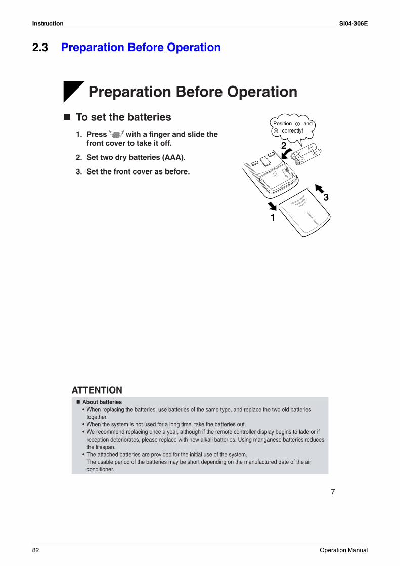
Instruction Si04-306E
2.3 Preparation Before Operation
7
Preparation Before Operation
To set the batteries
1. Press with a finger and slide the front cover to take it off.
2. Set two dry batteries (AAA).
3. Set the front cover as before.
ATTENTIONAbout batteries• When replacing the batteries, use batteries of the same type, and replace the two old batteries
together.• When the system is not used for a long time, take the batteries out.• We recommend replacing once a year, although if the remote controller display begins to fade or if
reception deteriorates, please replace with new alkali batteries. Using manganese batteries reduces the lifespan.
• The attached batteries are provided for the initial use of the system.The usable period of the batteries may be short depending on the manufactured date of the air conditioner.
+–
–+
2
3
1
Position + and – correctly!
82 Operation Manual
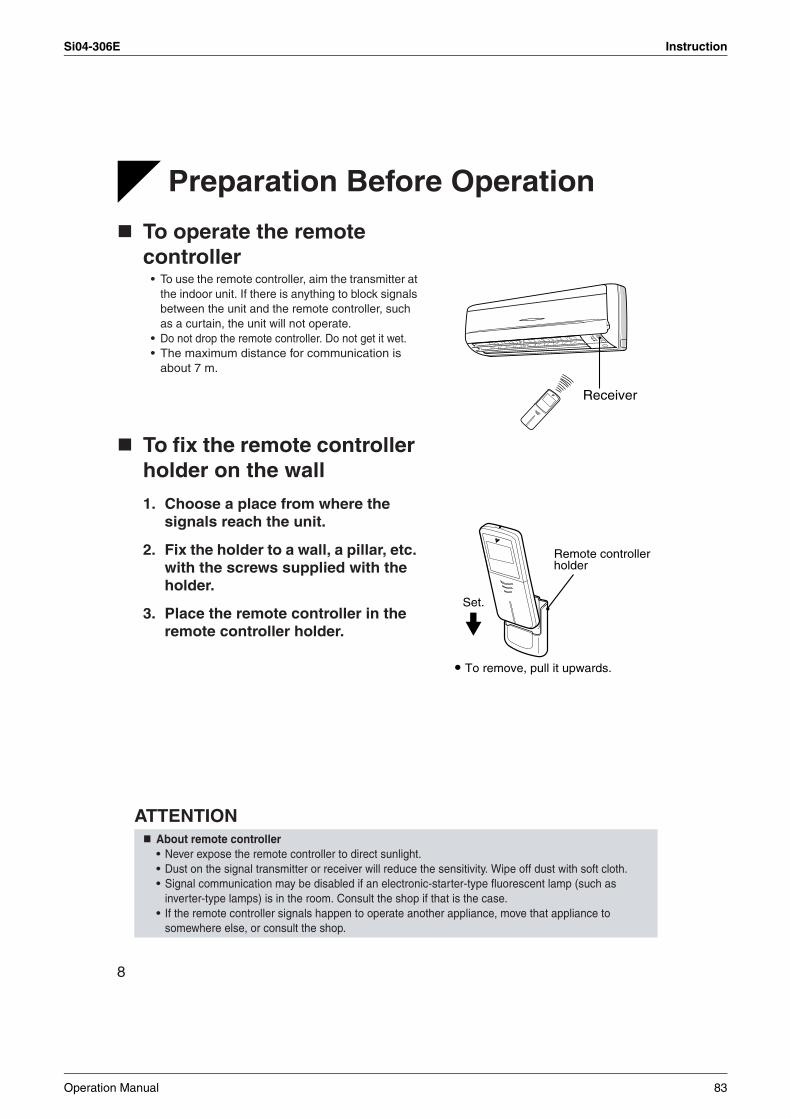
Si04-306E Instruction
8
Preparation Before Operation
To operate the remote controller • To use the remote controller, aim the transmitter at
the indoor unit. If there is anything to block signals between the unit and the remote controller, such as a curtain, the unit will not operate.
• Do not drop the remote controller. Do not get it wet. • The maximum distance for communication is
about 7 m.
To fix the remote controller holder on the wall
1. Choose a place from where the signals reach the unit.
2. Fix the holder to a wall, a pillar, etc. with the screws supplied with the holder.
3. Place the remote controller in the remote controller holder.
ATTENTION About remote controller
• Never expose the remote controller to direct sunlight.• Dust on the signal transmitter or receiver will reduce the sensitivity. Wipe off dust with soft cloth.• Signal communication may be disabled if an electronic-starter-type fluorescent lamp (such as
inverter-type lamps) is in the room. Consult the shop if that is the case.• If the remote controller signals happen to operate another appliance, move that appliance to
somewhere else, or consult the shop.
Receiver
Remote controller holder
Set.
To remove, pull it upwards.
Operation Manual 83
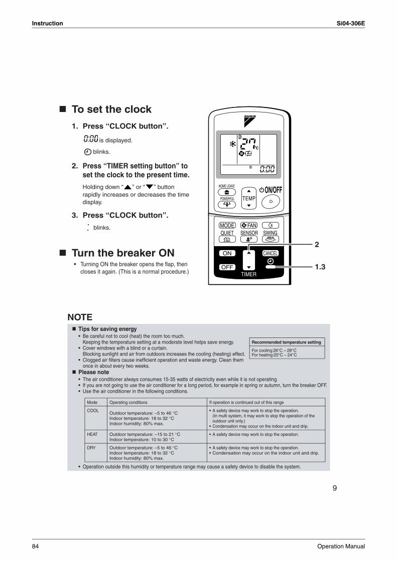
Instruction Si04-306E
9
To set the clock
1. Press “CLOCK button”.
is displayed.
blinks.
2. Press “TIMER setting button” to set the clock to the present time.
Holding down “ ” or “ ” button rapidly increases or decreases the time display.
3. Press “CLOCK button”.
blinks.
Turn the breaker ON• Turning ON the breaker opens the flap, then
closes it again. (This is a normal procedure.)
NOTETips for saving energy• Be careful not to cool (heat) the room too much.
Keeping the temperature setting at a moderate level helps save energy.• Cover windows with a blind or a curtain.
Blocking sunlight and air from outdoors increases the cooling (heating) effect.• Clogged air filters cause inefficient operation and waste energy. Clean them
once in about every two weeks.Please note• The air conditioner always consumes 15-35 watts of electricity even while it is not operating.• If you are not going to use the air conditioner for a long period, for example in spring or autumn, turn the breaker OFF.• Use the air conditioner in the following conditions.
• Operation outside this humidity or temperature range may cause a safety device to disable the system.
C
TEMPON/OFF
POWERFUL
HOME LEAVE
MODE
TIMER
FANQUIET SWING
ON CANCEL
OFF
SENSOR
1.3
2
Recommended temperature setting
For cooling:26°C – 28°CFor heating:20°C – 24°C
Mode Operating conditions If operation is continued out of this range
COOLOutdoor temperature: –5 to 46 °CIndoor temperature: 18 to 32 °CIndoor humidity: 80% max.
• A safety device may work to stop the operation.(In multi system, it may work to stop the operation of the outdoor unit only.)
• Condensation may occur on the indoor unit and drip.
HEAT Outdoor temperature: –15 to 21 °CIndoor temperature: 10 to 30 °C
• A safety device may work to stop the operation.
DRY Outdoor temperature: –5 to 46 °CIndoor temperature: 18 to 32 °CIndoor humidity: 80% max.
• A safety device may work to stop the operation.• Condensation may occur on the indoor unit and drip.
84 Operation Manual
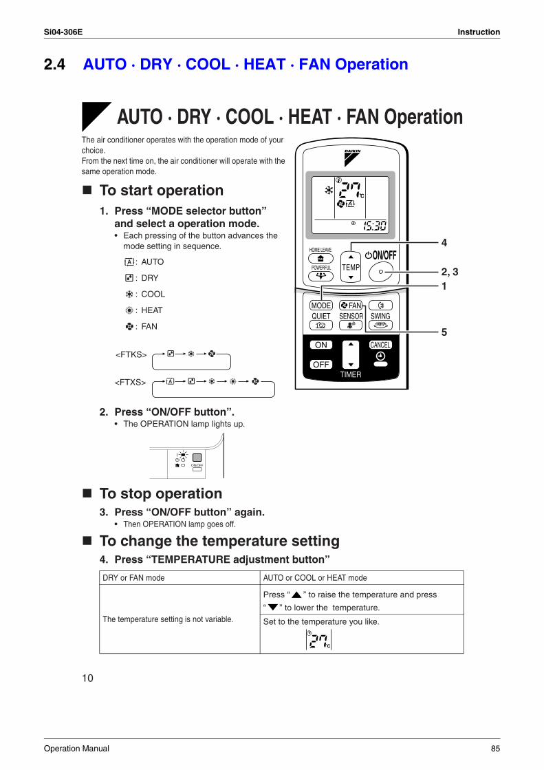
Si04-306E Instruction
2.4 AUTO · DRY · COOL · HEAT · FAN Operation
10
OPERATION
AUTO · DRY · COOL · HEAT · FAN OperationThe air conditioner operates with the operation mode of your choice.From the next time on, the air conditioner will operate with the same operation mode.
To start operation1. Press “MODE selector button”
and select a operation mode.• Each pressing of the button advances the
mode setting in sequence.
: AUTO
: DRY
: COOL
: HEAT
: FAN
2. Press “ON/OFF button”.• The OPERATION lamp lights up.
To stop operation3. Press “ON/OFF button” again.
• Then OPERATION lamp goes off.
To change the temperature setting4. Press “TEMPERATURE adjustment button”
DRY or FAN mode AUTO or COOL or HEAT mode
The temperature setting is not variable.
Press “ ” to raise the temperature and press
“ ” to lower the temperature.
Set to the temperature you like.
C
TEMPON/OFF
POWERFUL
HOME LEAVE
MODE
TIMER
FANQUIET SWING
ON CANCEL
OFF
SENSOR
2, 31
4
5
<FTKS>
<FTXS>
C
Operation Manual 85
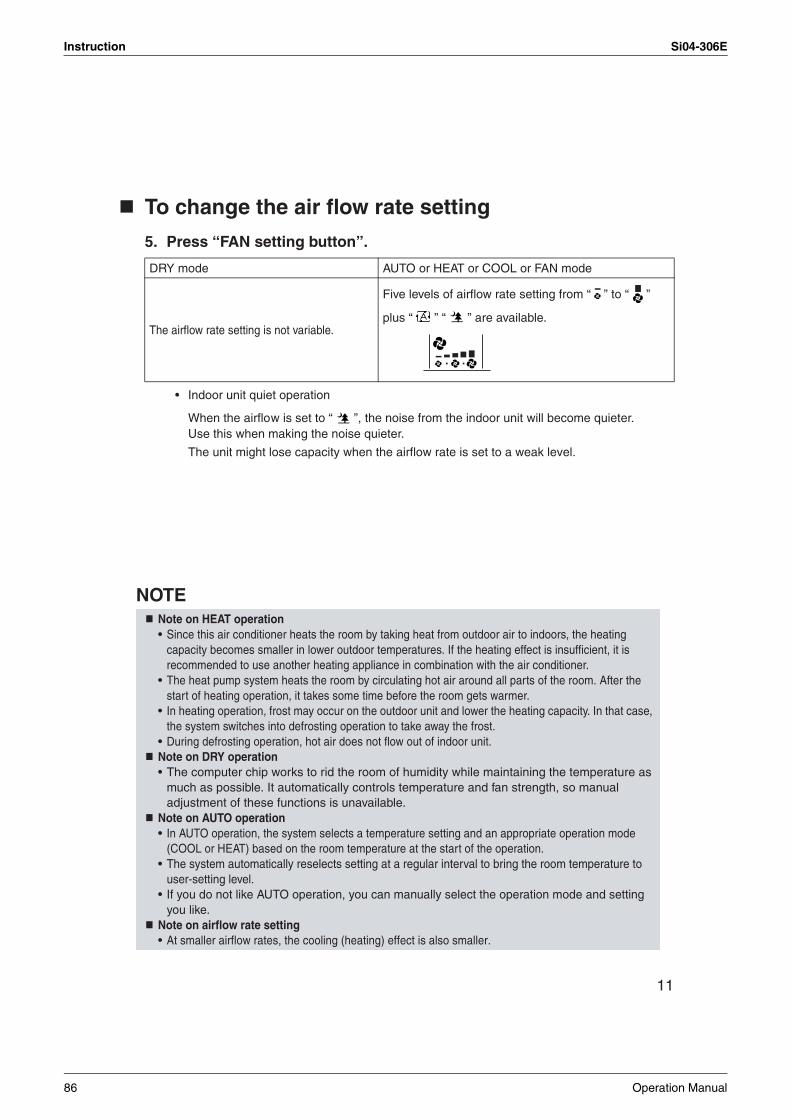
Instruction Si04-306E
11
To change the air flow rate setting
5. Press “FAN setting button”.
• Indoor unit quiet operation
When the airflow is set to “ ”, the noise from the indoor unit will become quieter. Use this when making the noise quieter.
The unit might lose capacity when the airflow rate is set to a weak level.
NOTE
DRY mode AUTO or HEAT or COOL or FAN mode
The airflow rate setting is not variable.
Five levels of airflow rate setting from “ ” to “ ”
plus “ ” “ ” are available.
Note on HEAT operation• Since this air conditioner heats the room by taking heat from outdoor air to indoors, the heating
capacity becomes smaller in lower outdoor temperatures. If the heating effect is insufficient, it is recommended to use another heating appliance in combination with the air conditioner.
• The heat pump system heats the room by circulating hot air around all parts of the room. After the start of heating operation, it takes some time before the room gets warmer.
• In heating operation, frost may occur on the outdoor unit and lower the heating capacity. In that case, the system switches into defrosting operation to take away the frost.
• During defrosting operation, hot air does not flow out of indoor unit.Note on DRY operation• The computer chip works to rid the room of humidity while maintaining the temperature as
much as possible. It automatically controls temperature and fan strength, so manual adjustment of these functions is unavailable.
Note on AUTO operation• In AUTO operation, the system selects a temperature setting and an appropriate operation mode
(COOL or HEAT) based on the room temperature at the start of the operation.• The system automatically reselects setting at a regular interval to bring the room temperature to
user-setting level.• If you do not like AUTO operation, you can manually select the operation mode and setting
you like.Note on airflow rate setting• At smaller airflow rates, the cooling (heating) effect is also smaller.
86 Operation Manual
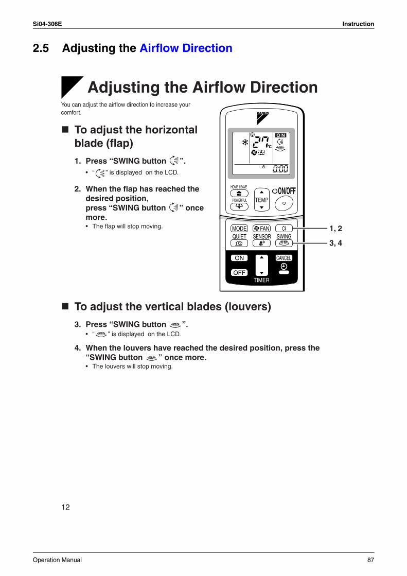
Si04-306E Instruction
2.5 Adjusting the Airflow Direction
12
Adjusting the Airflow DirectionYou can adjust the airflow direction to increase your comfort.
To adjust the horizontal blade (flap)
1. Press “SWING button ”.• “ ” is displayed on the LCD.
2. When the flap has reached the desired position, press “SWING button ” once more.• The flap will stop moving.
To adjust the vertical blades (louvers)
3. Press “SWING button ”.• “ ” is displayed on the LCD.
4. When the louvers have reached the desired position, press the “SWING button ” once more.• The louvers will stop moving.
C
TEMPON/OFF
POWERFUL
HOME LEAVE
MODE
TIMER
FANQUIET SWING
ON CANCEL
OFF
O N
SENSOR1, 2
3, 4
Operation Manual 87
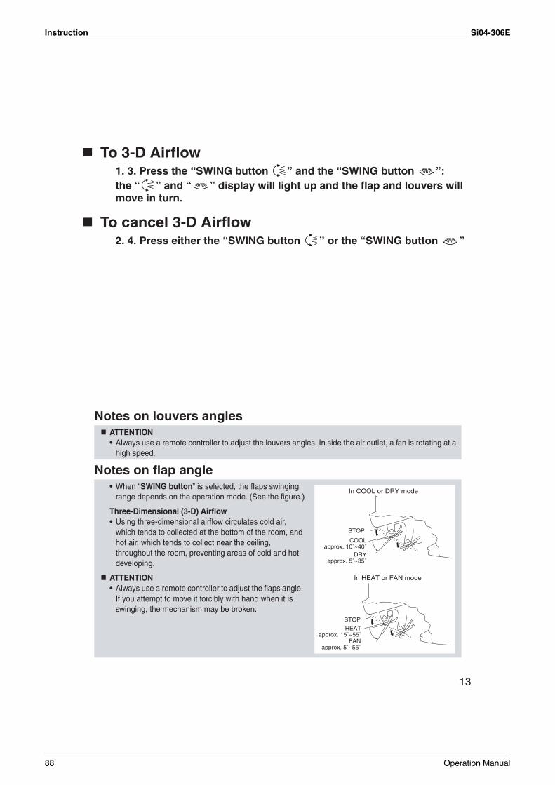
Instruction Si04-306E
13
To 3-D Airflow1. 3. Press the “SWING button ” and the “SWING button ”:the “ ” and “ ” display will light up and the flap and louvers will move in turn.
To cancel 3-D Airflow2. 4. Press either the “SWING button ” or the “SWING button ”
Notes on louvers angles
Notes on flap angle
ATTENTION• Always use a remote controller to adjust the louvers angles. In side the air outlet, a fan is rotating at a
high speed.
• When “SWING button” is selected, the flaps swinging range depends on the operation mode. (See the figure.)
Three-Dimensional (3-D) Airflow• Using three-dimensional airflow circulates cold air,
which tends to collected at the bottom of the room, and hot air, which tends to collect near the ceiling, throughout the room, preventing areas of cold and hot developing.
ATTENTION• Always use a remote controller to adjust the flaps angle.
If you attempt to move it forcibly with hand when it is swinging, the mechanism may be broken.
STOP
COOLapprox. 10˚~40˚
DRYapprox. 5˚~35˚
In COOL or DRY mode
STOP
HEATapprox. 15˚~55˚
In HEAT or FAN mode
FANapprox. 5˚~55˚
88 Operation Manual
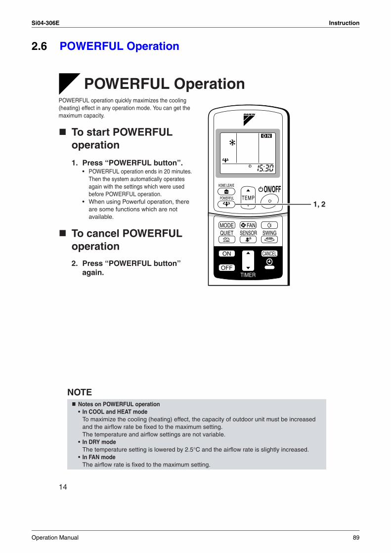
Si04-306E Instruction
2.6 POWERFUL Operation
14
POWERFUL OperationPOWERFUL operation quickly maximizes the cooling (heating) effect in any operation mode. You can get the maximum capacity.
To start POWERFUL operation
1. Press “POWERFUL button”.• POWERFUL operation ends in 20 minutes.
Then the system automatically operates again with the settings which were used before POWERFUL operation.
• When using Powerful operation, there are some functions which are not available.
To cancel POWERFUL operation
2. Press “POWERFUL button” again.
NOTENotes on POWERFUL operation• In COOL and HEAT mode
To maximize the cooling (heating) effect, the capacity of outdoor unit must be increased and the airflow rate be fixed to the maximum setting.The temperature and airflow settings are not variable.
• In DRY modeThe temperature setting is lowered by 2.5°C and the airflow rate is slightly increased.
• In FAN modeThe airflow rate is fixed to the maximum setting.
TEMPON/OFF
POWERFUL
HOME LEAVE
MODE
TIMER
FANQUIET SWING
ON CANCEL
OFF
O N
SENSOR
1, 2
Operation Manual 89
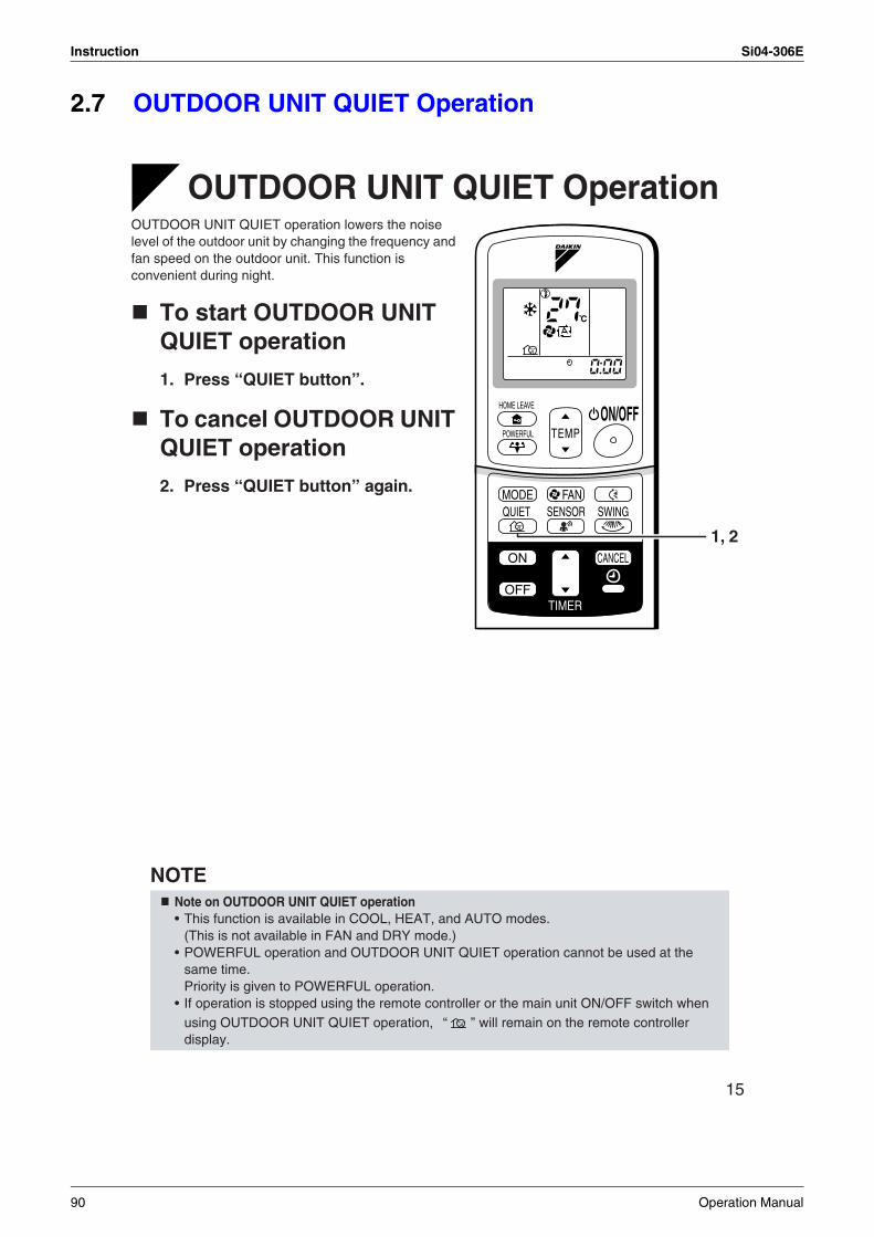
Instruction Si04-306E
2.7 OUTDOOR UNIT QUIET Operation
15
OUTDOOR UNIT QUIET OperationOUTDOOR UNIT QUIET operation lowers the noise level of the outdoor unit by changing the frequency and fan speed on the outdoor unit. This function is convenient during night.
To start OUTDOOR UNIT QUIET operation
1. Press “QUIET button”.
To cancel OUTDOOR UNIT QUIET operation
2. Press “QUIET button” again.
NOTENote on OUTDOOR UNIT QUIET operation• This function is available in COOL, HEAT, and AUTO modes.
(This is not available in FAN and DRY mode.)• POWERFUL operation and OUTDOOR UNIT QUIET operation cannot be used at the
same time. Priority is given to POWERFUL operation.
• If operation is stopped using the remote controller or the main unit ON/OFF switch when using OUTDOOR UNIT QUIET operation, “ ” will remain on the remote controller display.
C
TEMPON/OFF
POWERFUL
HOME LEAVE
MODE
TIMER
FANQUIET SWING
ON CANCEL
OFF
SENSOR
1, 2
90 Operation Manual
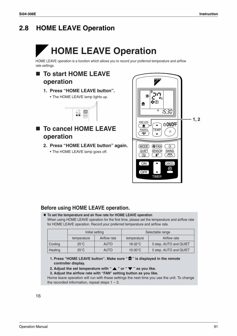
Si04-306E Instruction
2.8 HOME LEAVE Operation
16
HOME LEAVE OperationHOME LEAVE operation is a function which allows you to record your preferred temperature and airflow rate settings.
To start HOME LEAVE operation1. Press “HOME LEAVE button”.
• The HOME LEAVE lamp lights up.
To cancel HOME LEAVE operation2. Press “HOME LEAVE button” again.
• The HOME LEAVE lamp goes off.
Before using HOME LEAVE operation.To set the temperature and air flow rate for HOME LEAVE operationWhen using HOME LEAVE operation for the first time, please set the temperature and airflow rate for HOME LEAVE operation. Record your preferred temperature and airflow rate.
1. Press “HOME LEAVE button”. Make sure “ ” is displayed in the remote controller display.
2. Adjust the set temperature with “ ” or “ ” as you like.3. Adjust the airflow rate with “FAN” setting button as you like.
Home leave operation will run with these settings the next time you use the unit. To change the recorded information, repeat steps 1 – 3.
C
TEMPON/OFF
POWERFUL
HOME LEAVE
MODE
TIMER
FANQUIET SWING
ON CANCEL
OFF
SENSOR
1, 2
Initial setting Selectable range
temperature Airflow rate temperature Airflow rate
Cooling 25°C AUTO
AUTO
18-32°C 5 step, AUTO and QUIET
Heating 25°C 10-30°C 5 step, AUTO and QUIET
Operation Manual 91
Instruction Si04-306E
17
What’s the HOME LEAVE operationIs there a set temperature and airflow rate which is most comfortable, a set temperature and airflow rate which you use the most? HOME LEAVE operation is a function that allows you to record your favorite set temperature and airflow rate. You can start your favorite operation mode simply by pressing the HOME LEAVE button on the remote controller. This function is convenient in the following situations.
Useful in these cases.1.Use as an energy-saving mode
Set the temperature 2-3°C higher (cooling) or lower (heating) than normal. Setting the fan strength to the lowest setting allows the unit to be used in energy-saving mode. Also convenient for use while you are out or sleeping.
• Every day before you leave the house...
• Before bed...
2.Use as a favorite modeOnce you record the temperature and airflow rate settings you most often use, you can retrieve them by pressing HOME LEAVE button. You do not have to go through troublesome remote control operations.
NOTE
When you go out, push the “HOME LEAVE Operation” button, and the air conditioner will adjust capacity to reach the preset temperature for HOME LEAVE Operation.
When you return, you will be welcomed by a comfortably air conditioned room.
Push the “HOME LEAVE Operation” button again, and the air conditioner will adjust capacity to the set temperature for normal operation.
Set the unit to HOME LEAVE Operation before leaving the living room when going to bed.
The unit will maintain the temperature in the room at a comfortable level while you sleep.
When you enter the living room in the morning, the temperature will be just right. Disengaging HOME LEAVE Operation will return the temperature to that set for normal operation. Even the coldest winters will pose no problem!
• Once the temperature and airflow rate for HOME LEAVE operation are set, those settings will be used whenever HOME LEAVE operation is used in the future. To change these settings, please refer to the “Before using HOME LEAVE operation” section above.
• HOME LEAVE operation is only available in COOL and HEAT mode. Cannot be used in AUTO, DRY, and FAN mode.
• HOME LEAVE operation runs in accordance with the previous operation mode (COOL or HEAT) before using HOME LEAVE operation.
• HOME LEAVE operation and POWERFUL operation cannot be used at the same time. Last button that was pressed has priority.
• The operation mode cannot be changed while HOME LEAVE operation is being used.• When operation is shut off during HOME LEAVE operation, using the remote controller or the indoor
unit ON/OFF switch, “ ” will remain on the remote controller display.
92 Operation Manual
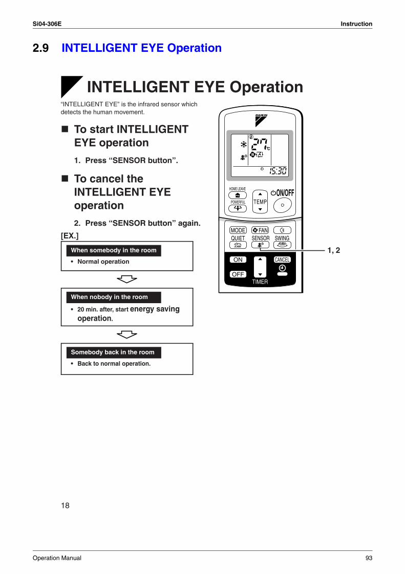
Si04-306E Instruction
2.9 INTELLIGENT EYE Operation
18
INTELLIGENT EYE Operation“INTELLIGENT EYE” is the infrared sensor which detects the human movement.
To start INTELLIGENT EYE operation
1. Press “SENSOR button”.
To cancel the INTELLIGENT EYE operation
2. Press “SENSOR button” again.
[EX.]
C
TEMPON/OFF
POWERFUL
HOME LEAVE
MODE
TIMER
FANQUIET
ON CANCEL
OFF
SWING
1, 2
SENSOR
When somebody in the room
• Normal operation
When nobody in the room
• 20 min. after, start energy saving operation.
Somebody back in the room
• Back to normal operation.
Operation Manual 93
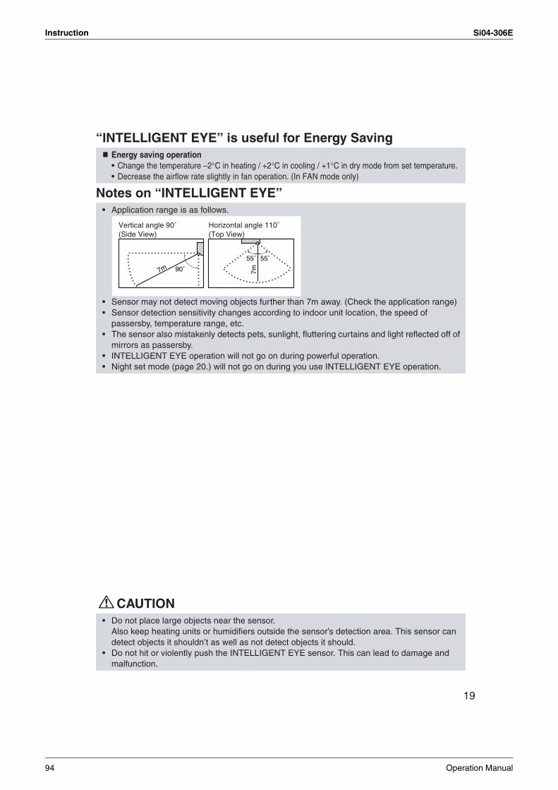
Instruction Si04-306E
19
“INTELLIGENT EYE” is useful for Energy Saving
Notes on “INTELLIGENT EYE”
CAUTION
Energy saving operation• Change the temperature –2°C in heating / +2°C in cooling / +1°C in dry mode from set temperature.• Decrease the airflow rate slightly in fan operation. (In FAN mode only)
• Application range is as follows.
• Sensor may not detect moving objects further than 7m away. (Check the application range)• Sensor detection sensitivity changes according to indoor unit location, the speed of
passersby, temperature range, etc.• The sensor also mistakenly detects pets, sunlight, fluttering curtains and light reflected off of
mirrors as passersby.• INTELLIGENT EYE operation will not go on during powerful operation.• Night set mode (page 20.) will not go on during you use INTELLIGENT EYE operation.
• Do not place large objects near the sensor.Also keep heating units or humidifiers outside the sensor’s detection area. This sensor can detect objects it shouldn’t as well as not detect objects it should.
• Do not hit or violently push the INTELLIGENT EYE sensor. This can lead to damage and malfunction.
90˚
55˚7m
55˚
7m
Vertical angle 90˚(Side View)
Horizontal angle 110˚(Top View)
94 Operation Manual
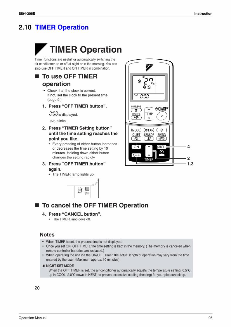
Si04-306E Instruction
2.10 TIMER Operation
20
TIMER OperationTimer functions are useful for automatically switching the air conditioner on or off at night or in the morning. You can also use OFF TIMER and ON TIMER in combination.
To use OFF TIMER operation• Check that the clock is correct.
If not, set the clock to the present time. (page 9.)
1. Press “OFF TIMER button”.
is displayed.
blinks.
2. Press “TIMER Setting button” until the time setting reaches the point you like.• Every pressing of either button increases
or decreases the time setting by 10 minutes. Holding down either button changes the setting rapidly.
3. Press “OFF TIMER button” again.• The TIMER lamp lights up.
To cancel the OFF TIMER Operation4. Press “CANCEL button”.
• The TIMER lamp goes off.
Notes• When TIMER is set, the present time is not displayed.• Once you set ON, OFF TIMER, the time setting is kept in the memory. (The memory is canceled when
remote controller batteries are replaced.)• When operating the unit via the ON/OFF Timer, the actual length of operation may vary from the time
entered by the user. (Maximum approx. 10 minutes)
NIGHT SET MODEWhen the OFF TIMER is set, the air conditioner automatically adjusts the temperature setting (0.5˚C up in COOL, 2.0˚C down in HEAT) to prevent excessive cooling (heating) for your pleasant sleep.
C
TEMPON/OFF
POWERFUL
HOME LEAVE
MODE
TIMER
FANQUIET SWING
ON CANCEL
OFF
SENSOR
4
21.3
Operation Manual 95
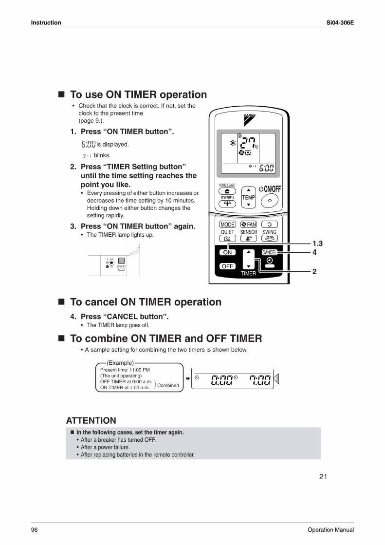
Instruction Si04-306E
21
To use ON TIMER operation• Check that the clock is correct. If not, set the
clock to the present time (page 9.).
1. Press “ON TIMER button”.
is displayed.
blinks.
2. Press “TIMER Setting button” until the time setting reaches the point you like.• Every pressing of either button increases or
decreases the time setting by 10 minutes. Holding down either button changes the setting rapidly.
3. Press “ON TIMER button” again.• The TIMER lamp lights up.
To cancel ON TIMER operation4. Press “CANCEL button”.
• The TIMER lamp goes off.
To combine ON TIMER and OFF TIMER• A sample setting for combining the two timers is shown below.
ATTENTIONIn the following cases, set the timer again.• After a breaker has turned OFF.• After a power failure.• After replacing batteries in the remote controller.
C
TEMPON/OFF
POWERFUL
HOME LEAVE
MODE
TIMER
FANQUIET SWING
ON CANCEL
OFF
SENSOR
2
1.34
Dis
play
(Example)Present time: 11:00 PM (The unit operating)OFF TIMER at 0:00 a.m.ON TIMER at 7:00 a.m. Combined
96 Operation Manual
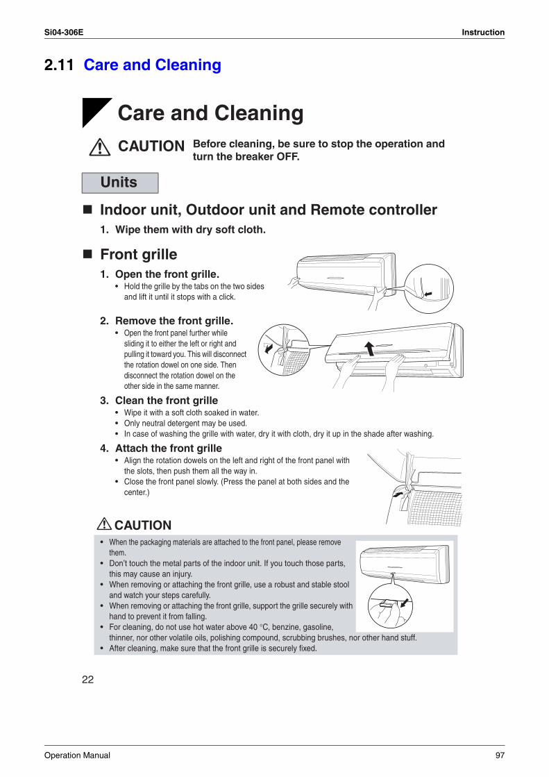
Si04-306E Instruction
2.11 Care and Cleaning
22
CARE
Care and CleaningCAUTION
Indoor unit, Outdoor unit and Remote controller1. Wipe them with dry soft cloth.
Front grille1. Open the front grille.
• Hold the grille by the tabs on the two sides and lift it until it stops with a click.
2. Remove the front grille.• Open the front panel further while
sliding it to either the left or right and pulling it toward you. This will disconnect the rotation dowel on one side. Then disconnect the rotation dowel on the other side in the same manner.
3. Clean the front grille• Wipe it with a soft cloth soaked in water.• Only neutral detergent may be used.• In case of washing the grille with water, dry it with cloth, dry it up in the shade after washing.
4. Attach the front grille• Align the rotation dowels on the left and right of the front panel with
the slots, then push them all the way in.• Close the front panel slowly. (Press the panel at both sides and the
center.)
CAUTION
Units
• When the packaging materials are attached to the front panel, please remove them.
• Don’t touch the metal parts of the indoor unit. If you touch those parts, this may cause an injury.
• When removing or attaching the front grille, use a robust and stable stool and watch your steps carefully.
• When removing or attaching the front grille, support the grille securely with hand to prevent it from falling.
• For cleaning, do not use hot water above 40 °C, benzine, gasoline, thinner, nor other volatile oils, polishing compound, scrubbing brushes, nor other hand stuff.
• After cleaning, make sure that the front grille is securely fixed.
Before cleaning, be sure to stop the operation and turn the breaker OFF.
Operation Manual 97
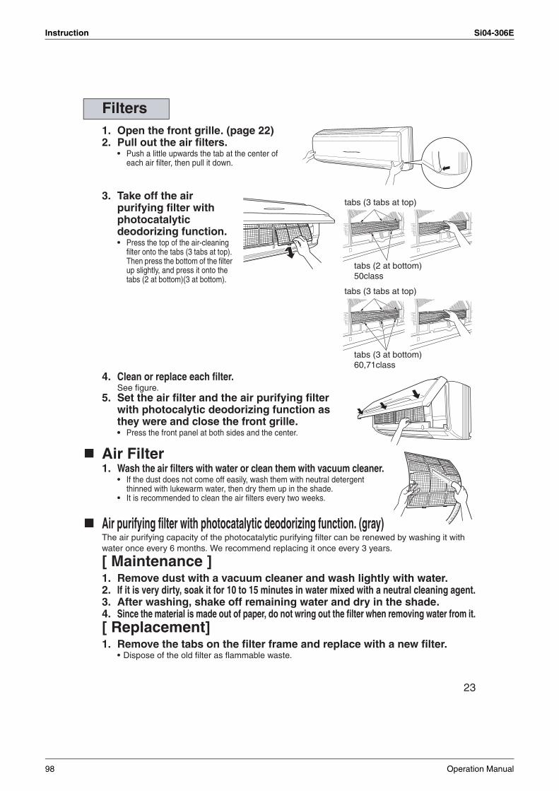
Instruction Si04-306E
23
1. Open the front grille. (page 22)2. Pull out the air filters.
• Push a little upwards the tab at the center of each air filter, then pull it down.
3. Take off the air purifying filter with photocatalytic deodorizing function.• Press the top of the air-cleaning
filter onto the tabs (3 tabs at top). Then press the bottom of the filter up slightly, and press it onto the tabs (2 at bottom)(3 at bottom).
4. Clean or replace each filter.See figure.
5. Set the air filter and the air purifying filter with photocalytic deodorizing function as they were and close the front grille.• Press the front panel at both sides and the center.
Air Filter1. Wash the air filters with water or clean them with vacuum cleaner.
• If the dust does not come off easily, wash them with neutral detergent thinned with lukewarm water, then dry them up in the shade.
• It is recommended to clean the air filters every two weeks.
Air purifying filter with photocatalytic deodorizing function. (gray)The air purifying capacity of the photocatalytic purifying filter can be renewed by washing it with water once every 6 months. We recommend replacing it once every 3 years.
[ Maintenance ]1. Remove dust with a vacuum cleaner and wash lightly with water.2. If it is very dirty, soak it for 10 to 15 minutes in water mixed with a neutral cleaning agent.3. After washing, shake off remaining water and dry in the shade.4. Since the material is made out of paper, do not wring out the filter when removing water from it.[ Replacement]1. Remove the tabs on the filter frame and replace with a new filter.
• Dispose of the old filter as flammable waste.
Filters
tabs (3 tabs at top)
tabs (2 at bottom)50class
tabs (3 tabs at top)
tabs (3 at bottom)60,71class
98 Operation Manual
Si04-306E Instruction
24
Check
Before a long idle period
1. Operate the “FAN only” for several hours on a fine day to dry out the inside.• Press “MODE” button and select “FAN” operation.
• Press “ON/OFF” button and start operation.
2. After operation stops, turn off the breaker for the room air conditioner.
3. Clean the air filters and set them again.
4. Take out batteries from the remote controller.
NOTE
Check that the base, stand and other fittings of the outdoor unit are not decayed or corroded.
Check that nothing blocks the air inlets and the outlets of the indoor unit and the outdoor unit.
Check that the drain comes smoothly out of the drain hose during COOL or DRY operation.• If no drain water is seen, water may be leaking from the indoor unit. Stop operation and consult the
service shop if this is the case.
• Operation with dirty filters: (1) cannot deodorize the air. (2) cannot clean the air. (3) results in poor heating or cooling. (4) may cause odour.
• To order air purifying filter with photocatalytic deodorizing function contact to the service shop there you bought the air conditioner.
• Dispose of old air filter as non-burnable and photocatalytic deodorizing filters as burnable waste.
Item Part No.
Air purifying filter with photocatalytic deodorizing function. (without frame) 1 set KAF952A42
Operation Manual 99
Instruction Si04-306E
2.12 Troubleshooting
25
Trouble Shooting
The following cases are not air conditioner troubles but have some reasons. You may just continue using it.
These cases are not troubles.
Case ExplanationOperation does not start soon.• When ON/OFF button was
pressed soon after operation was stopped.
• When the mode was reselected.
• This is to protect the air conditioner.You should wait for about 3 minutes.
Hot air does not flow out soon after the start of heating operation.
• The air conditioner is warming up. You should wait for 1 to 4 minutes.(The system is designed to start discharging air only after it has reached a certain temperature.)
The heating operation stops suddenly and a flowing sound is heard.
• The system is taking away the frost on the outdoor unit.You should wait for about 4 to 12 minutes.
The outdoor unit emits water or steam.
In HEAT mode• The frost on the outdoor unit melts into water or steam
when the air conditioner is in defrost operation.In COOL or DRY mode• Moisture in the air condenses into water on the cool
surface of outdoor unit piping and drips.
Mists come out of the indoor unit.
This happens when the air in the room is cooled into mist by the cold airflow during cooling operation.
The indoor unit gives out odour. This happens when smells of the room, furniture, or cigarettes are absorbed into the unit and discharged with the airflow.(If this happens, we recommend you to have the indoor unit washed by a technician. Consult the service shop where you bought the air conditioner.)
The outdoor fan rotates while the air conditioner is not in operation.
After operation is stopped:• The outdoor fan continues rotating for another 60
seconds for system protection.While the air conditioner is not in operation:• When the outdoor temperature is very high, the out door
fan starts rotating for system protection.
The operation stopped suddenly.(OPERATION lamp is on)
For system protection, the air conditioner may stop operating on a sudden large voltage fluctuation.It automatically resumes operation in about 3 minutes.
100 Operation Manual
Si04-306E Instruction
26
Please check again before calling a repair person.
Check again.
Case CheckThe air conditioner does not operate.(OPERATION lamp is off)
• Hasn’t a breaker turned OFF or a fuse blown?• Isn’t it a power failure?• Are batteries set in the remote controller?• Is the timer setting correct?
Cooling (Heating) effect is poor. • Are the air filters clean?• Is there anything to block the air inlet or the outlet of the
indoor and the outdoor units?• Is the temperature setting appropriate?• Are the windows and doors closed?• Are the airflow rate and the air direction set appropriately?
Operation stops suddenly.(OPERATION lamp blinks.)
• Are the air filters clean?• Is there anything to block the air inlet or the outlet of the
indoor and the outdoor units?Clean the air filters or take all obstacles away and turn the breaker OFF. Then turn it ON again and try operating the air conditioner with the remote controller. If the lamp still blinks, call the service shop where you bought the air conditioner.
An abnormal functioninghappens during operation.
• The air conditioner may malfunction with lightening or radio waves. Turn the breaker OFF, turn it ON again and try operating the air conditioner with the remote controller.
Operation Manual 101
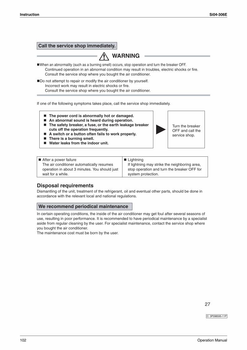
Instruction Si04-306E
27
WARNINGWhen an abnormality (such as a burning smell) occurs, stop operation and turn the breaker OFF.
Continued operation in an abnormal condition may result in troubles, electric shocks or fire.Consult the service shop where you bought the air conditioner.
Do not attempt to repair or modify the air conditioner by yourself.Incorrect work may result in electric shocks or fire.Consult the service shop where you bought the air conditioner.
If one of the following symptoms takes place, call the service shop immediately.
Disposal requirementsDismantling of the unit, treatment of the refrigerant, oil and eventual other parts, should be done in accordance with the relevant local and national regulations.
In certain operating conditions, the inside of the air conditioner may get foul after several seasons of use, resulting in poor performance. It is recommended to have periodical maintenance by a specialist aside from regular cleaning by the user. For specialist maintenance, contact the service shop where you bought the air conditioner.The maintenance cost must be born by the user.
Call the service shop immediately.
After a power failureThe air conditioner automatically resumes operation in about 3 minutes. You should just wait for a while.
LightningIf lightning may strike the neighboring area, stop operation and turn the breaker OFF for system protection.
We recommend periodical maintenance
The power cord is abnormally hot or damaged.An abnormal sound is heard during operation.The safety breaker, a fuse, or the earth leakage breaker cuts off the operation frequently. A switch or a button often fails to work properly.There is a burning smell.Water leaks from the indoor unit.
Turn the breaker OFF and call the service shop.
C: 3P098595-11P
102 Operation Manual
Si04-306E
Service Diagnosis 103
Part 6Service Diagnosis
1. Caution for Diagnosis..........................................................................1042. Problem Symptoms and Measures .....................................................1053. Service Check Function ......................................................................1064. Troubleshooting ..................................................................................109
4.1 Error Codes and Description ................................................................1094.2 Indoor Unit PCB Abnormality ...............................................................1104.3 Freeze-up Protection Control or High Pressure Control.......................1114.4 Fan Motor (DC Motor) or Related Abnormality.....................................1134.5 Thermistor or Related Abnormality (Indoor Unit)..................................1154.6 Signal Transmission Error (between Indoor and Outdoor Units)..........1164.7 OL Activation (Compressor Overload) .................................................1184.8 Compressor Lock .................................................................................1194.9 DC Fan Lock ........................................................................................1204.10 Input Over Current Detection ...............................................................1214.11 Four Way Valve Abnormality................................................................1234.12 Discharge Pipe Temperature Control...................................................1254.13 High Pressure Control in Cooling .........................................................1264.14 Position Sensor Abnormality ................................................................1284.15 CT or Related Abnormality ...................................................................1294.16 Thermistor or Related Abnormality (Outdoor Unit)...............................1314.17 Electrical Box Temperature Rise..........................................................1334.18 Radiation Fin Temperature Rise ..........................................................1354.19 Output Over Current Detection.............................................................1374.20 Insufficient Gas.....................................................................................1394.21 Low-voltage Detection..........................................................................141
5. Check ..................................................................................................1425.1 How to Check .......................................................................................142
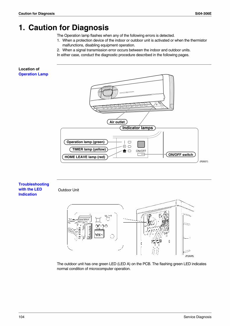
Caution for Diagnosis Si04-306E
1. Caution for DiagnosisThe Operation lamp flashes when any of the following errors is detected.1. When a protection device of the indoor or outdoor unit is activated or when the thermistor
malfunctions, disabling equipment operation.2. When a signal transmission error occurs between the indoor and outdoor units.In either case, conduct the diagnostic procedure described in the following pages.
Location of Operation Lamp
Troubleshooting with the LED Indication
The outdoor unit has one green LED (LED A) on the PCB. The flashing green LED indicates normal condition of microcomputer operation.
Operation lamp (green)
HOME LEAVE lamp (red)
TIMER lamp (yellow)
ON/OFF switch
Air outlet
Indicator lamps
(R2837)
Outdoor Unit
104 Service Diagnosis
Si04-306E Problem Symptoms and Measures
2. Problem Symptoms and MeasuresSymptom Check Item Details of Measure Reference
Page
None of the units operates. Check the power supply. Check to make sure that the rated voltage is supplied.
—
Check the type of the indoor units. Check to make sure that the indoor unit type is compatible with the outdoor unit.
—
Check the outdoor air temperature. Heating operation cannot be used when the outdoor air temperature is 24°C or higher (only for heat pump model), and cooling operation cannot be used when the outside temperature is below –5°C (–10°C for Europe).
—
Diagnosis with remote controller indication
— 109
Check the remote controller addresses.
Check to make sure that address settings for the remote controller and indoor unit are correct.
—
Operation sometimes stops.
Check the power supply. A power failure of 2 to 10 cycles can stop air conditioner operation. (Operation lamp OFF)
—
Check the outdoor air temperature. Heating operation cannot be used when the outdoor air temperature is 24°C or higher (only for heat pump model), and cooling operation cannot be used when the outside temperature is below –5°C (–10°C for Europe).
—
Diagnosis with remote controller indication
— 109
Equipment operates but does not cool, or does not heat (only for heat pump model).
Check for wiring and piping errors in the indoor and outdoor units connection wires and pipes.
Conduct the wiring/piping error check described on the product diagnosis nameplate.
—
Check for thermistor detection errors. Check to make sure that the main unit’s thermistor has not dismounted from the pipe holder.
—
Check for faulty operation of the electronic expansion valve.
Set the units to cooling operation, and compare the temperatures of the liquid side connection pipes of the connection section among rooms to check the opening and closing operation of the electronic expansion valves of the individual units.
—
Diagnosis with remote controller indication
— 109
Diagnosis by service port pressure and operating current
Check for insufficient gas. 147
Large operating noise and vibrations
Check the output voltage of the power transistor.
— 148
Check the power transistor. — —
Check the installation condition. Check to make sure that the required spaces for installation (specified in the Engineering Data Book, etc.) are provided.
—
Service Diagnosis 105
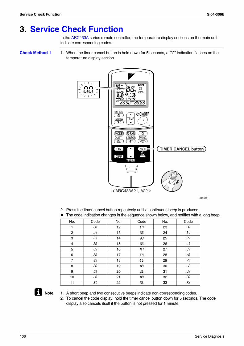
Service Check Function Si04-306E
3. Service Check FunctionIn the ARC433A series remote controller, the temperature display sections on the main unit indicate corresponding codes.
Check Method 1 1. When the timer cancel button is held down for 5 seconds, a “00” indication flashes on the temperature display section.
2. Press the timer cancel button repeatedly until a continuous beep is produced.The code indication changes in the sequence shown below, and notifies with a long beep.
Note: 1. A short beep and two consecutive beeps indicate non-corresponding codes.2. To cancel the code display, hold the timer cancel button down for 5 seconds. The code
display also cancels itself if the button is not pressed for 1 minute.
No. Code No. Code No. Code
1 00 12 C7 23 H0
2 U4 13 H8 24 E1
3 F3 14 J3 25 P4
4 E6 15 A3 26 L3
5 L5 16 A1 27 L4
6 A6 17 C4 28 H6
7 E5 18 C5 29 H7
8 F6 19 H9 30 U2
9 C9 20 J6 31 UH
10 U0 21 UA 32 EA
11 E7 22 A5 33 AH
< ARC433A21, A22 >(R8522)
C
O N
TEMPON/OFF
POWERFUL
HOME LEAVE
MODE
TIMER
FANQUIET SWING
ON CANCEL
OFF
SENSOR
TIMER CANCEL button
106 Service Diagnosis
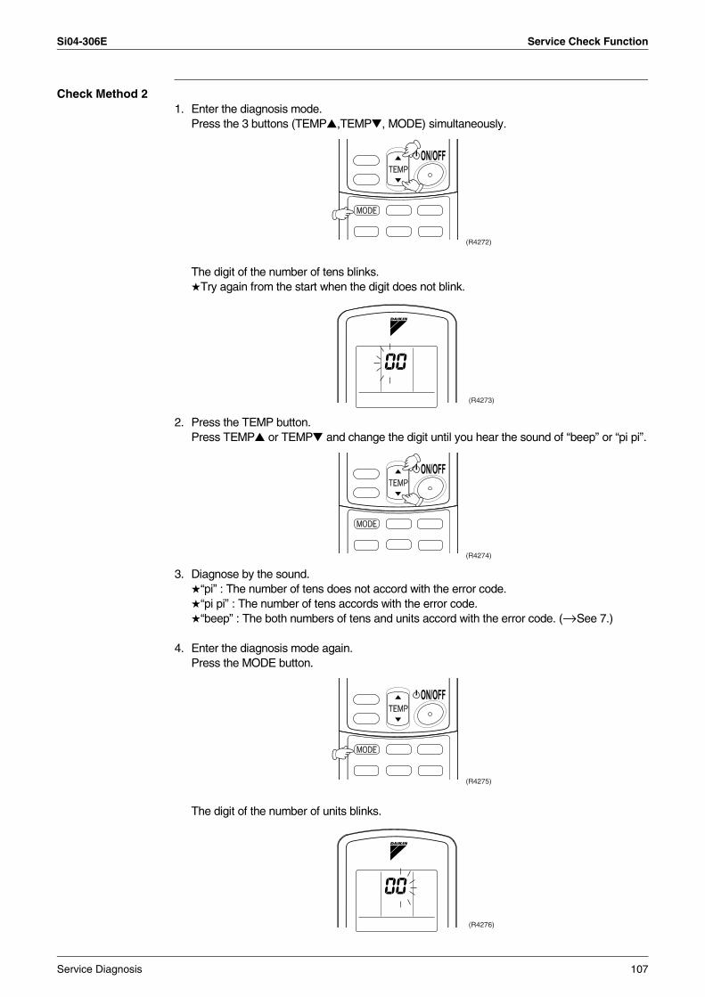
Si04-306E Service Check Function
Check Method 21. Enter the diagnosis mode.
Press the 3 buttons (TEMP,TEMP, MODE) simultaneously.
The digit of the number of tens blinks.Try again from the start when the digit does not blink.
2. Press the TEMP button.Press TEMP or TEMP and change the digit until you hear the sound of “beep” or “pi pi”.
3. Diagnose by the sound.“pi” : The number of tens does not accord with the error code.“pi pi” : The number of tens accords with the error code.“beep” : The both numbers of tens and units accord with the error code. (→See 7.)
4. Enter the diagnosis mode again.Press the MODE button.
The digit of the number of units blinks.
(R4272)
(R4273)
(R4274)
(R4275)
(R4276)
Service Diagnosis 107
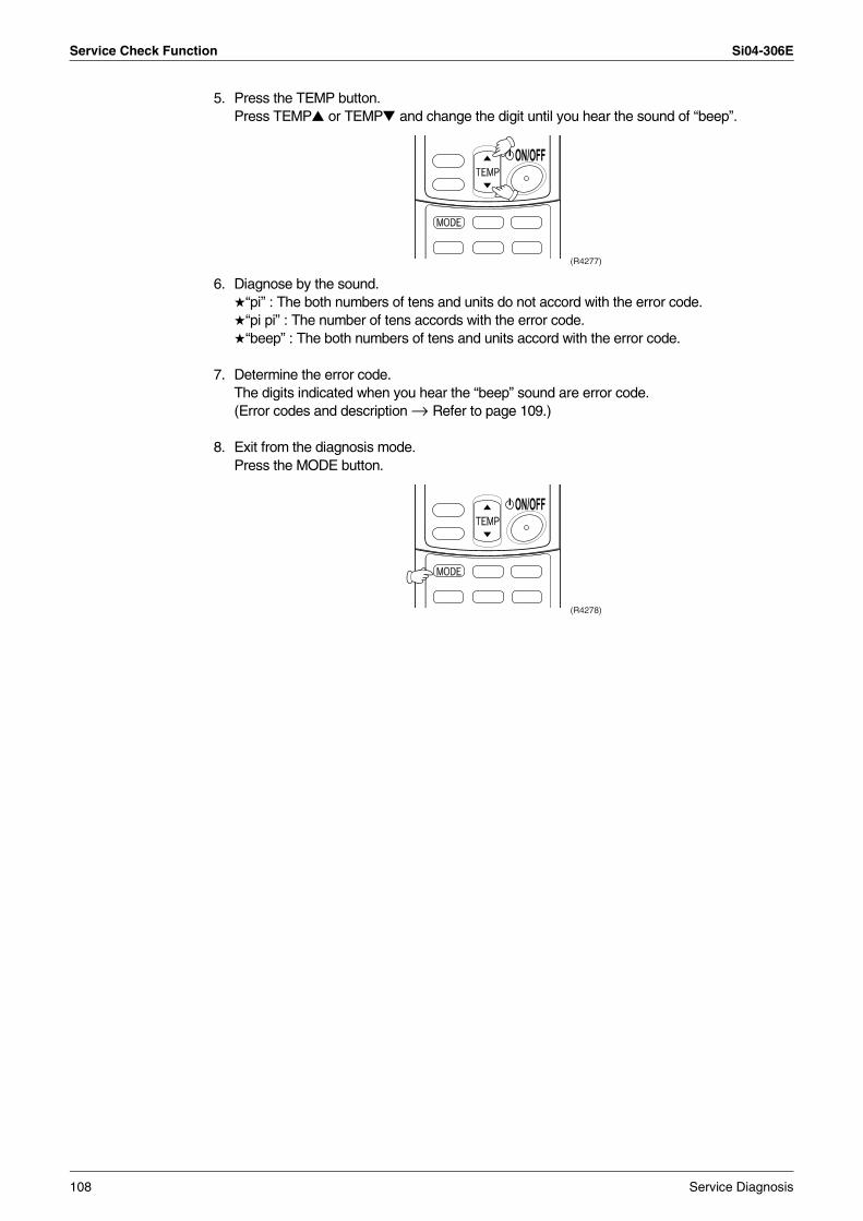
Service Check Function Si04-306E
5. Press the TEMP button.Press TEMP or TEMP and change the digit until you hear the sound of “beep”.
6. Diagnose by the sound.“pi” : The both numbers of tens and units do not accord with the error code.“pi pi” : The number of tens accords with the error code.“beep” : The both numbers of tens and units accord with the error code.
7. Determine the error code.The digits indicated when you hear the “beep” sound are error code.(Error codes and description → Refer to page 109.)
8. Exit from the diagnosis mode.Press the MODE button.
(R4277)
(R4278)
108 Service Diagnosis
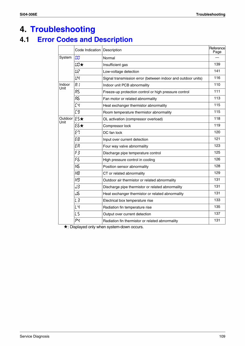
Si04-306E Troubleshooting
4. Troubleshooting4.1 Error Codes and Description
: Displayed only when system-down occurs.
Code Indication Description ReferencePage
System 00 Normal —
U0 Insufficient gas 139
U2 Low-voltage detection 141
U4 Signal transmission error (between indoor and outdoor units) 116
IndoorUnit
A1 Indoor unit PCB abnormality 110
A5 Freeze-up protection control or high pressure control 111
A6 Fan motor or related abnormality 113
C4 Heat exchanger thermistor abnormality 115
C9 Room temperature thermistor abnormality 115
OutdoorUnit
E5 OL activation (compressor overload) 118
E6 Compressor lock 119
E7 DC fan lock 120
E8 Input over current detection 121
EA Four way valve abnormality 123
F3 Discharge pipe temperature control 125
F6 High pressure control in cooling 126
H6 Position sensor abnormality 128
H8 CT or related abnormality 129
H9 Outdoor air thermistor or related abnormality 131
J3 Discharge pipe thermistor or related abnormality 131
J6 Heat exchanger thermistor or related abnormality 131
L3 Electrical box temperature rise 133
L4 Radiation fin temperature rise 135
L5 Output over current detection 137
P4 Radiation fin thermistor or related abnormality 131
Service Diagnosis 109
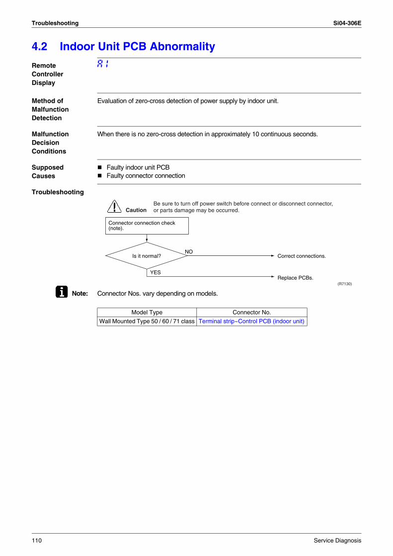
Troubleshooting Si04-306E
4.2 Indoor Unit PCB Abnormality
Remote Controller Display
A1
Method of Malfunction Detection
Evaluation of zero-cross detection of power supply by indoor unit.
Malfunction Decision Conditions
When there is no zero-cross detection in approximately 10 continuous seconds.
Supposed Causes
Faulty indoor unit PCBFaulty connector connection
Troubleshooting
Note: Connector Nos. vary depending on models.
Connector connection check (note).
Is it normal?
YES
NO
(R7130)
CautionBe sure to turn off power switch before connect or disconnect connector, or parts damage may be occurred.
Correct connections.
Replace PCBs.
Model Type Connector No.
Wall Mounted Type 50 / 60 / 71 class Terminal strip~Control PCB (indoor unit)
110 Service Diagnosis
Si04-306E Troubleshooting
4.3 Freeze-up Protection Control or High Pressure Control
Remote Controller Display
A5
Method of Malfunction Detection
High pressure control (heat pump model only)During heating operations, the temperature detected by the indoor heat exchanger thermistor is used for the high pressure control (stop, outdoor fan stop, etc.) The freeze-up protection control (operation halt) is activated during cooling operation according to the temperature detected by the indoor unit heat exchanger thermistor.
Malfunction Decision Conditions
High pressure controlDuring heating operations, the temperature detected by the indoor heat exchanger thermistor is above 65°CFreeze-up protectionWhen the indoor unit heat exchanger temperature is below 0°C during cooling operation.
Supposed Causes
Operation halt due to clogged air filter of the indoor unit.Operation halt due to dust accumulation on the indoor unit heat exchanger.Operation halt due to short-circuit.Detection error due to faulty indoor unit heat exchanger thermistor.Detection error due to faulty indoor unit PCB.
Service Diagnosis 111
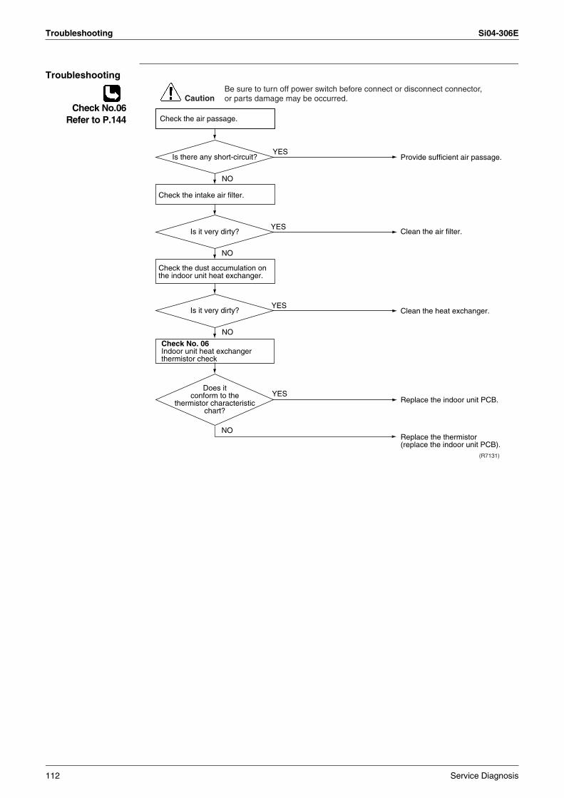
Troubleshooting Si04-306E
Troubleshooting
Check No.06Refer to P.144
NO
NO
NO
Check No. 06Indoor unit heat exchanger thermistor check
YES
YES
(R7131)
YES
YES
NO
CautionBe sure to turn off power switch before connect or disconnect connector, or parts damage may be occurred.
Provide sufficient air passage.
Clean the air filter.
Clean the heat exchanger.
Replace the indoor unit PCB.
Replace the thermistor (replace the indoor unit PCB).
Does it conform to the
thermistor characteristic chart?
Check the intake air filter.
Check the dust accumulation on the indoor unit heat exchanger.
Is there any short-circuit?
Is it very dirty?
Is it very dirty?
Check the air passage.
112 Service Diagnosis
Si04-306E Troubleshooting
4.4 Fan Motor (DC Motor) or Related Abnormality
Remote Controller Display
A6
Method of Malfunction Detection
The rotation speed detected by the Hall IC during fan motor operation is used to determine abnormal fan motor operation.
Malfunction Decision Conditions
When the detected rotation speed does not reach the demanded rotation speed of the target tap, and is less than 50% of the maximum fan motor rotation speed.
Supposed Causes
Operation halt due to short circuit inside the fan motor winding.Operation halt due to breaking of wire inside the fan motor.Operation halt due to breaking of the fan motor lead wires.Operation halt due to faulty capacitor of the fan motor.Detection error due to faulty indoor unit PCB.
Service Diagnosis 113
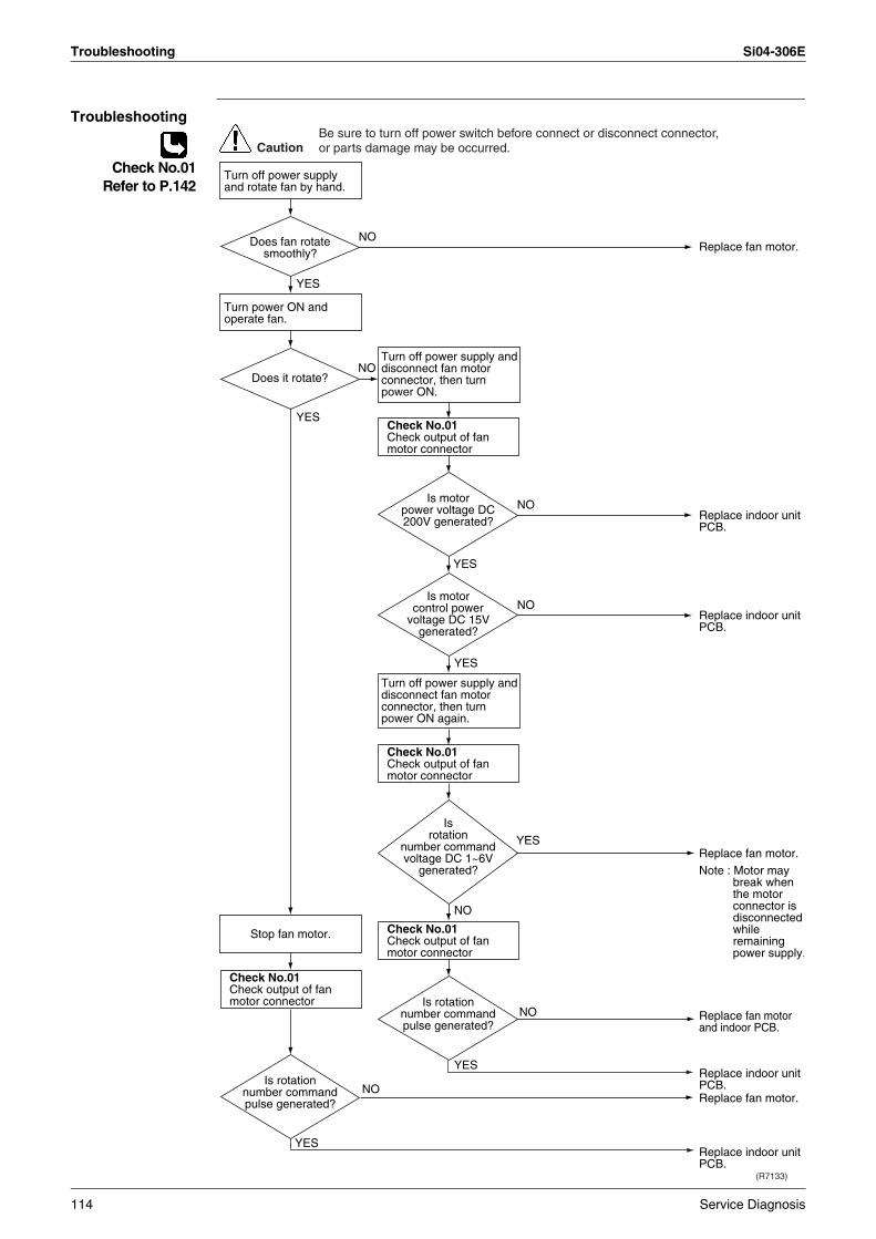
Troubleshooting Si04-306E
Troubleshooting
Check No.01Refer to P.142
Turn off power supply and disconnect fan motor connector, then turn power ON.
Turn off power supply and disconnect fan motor connector, then turn power ON again.
Check No.01Check output of fan motor connector
Check No.01Check output of fan motor connector
Check No.01Check output of fan motor connector
Check No.01Check output of fan motor connector
(R7133)
YES
YES
NO
YES
YES
NO
YES
NO
NO
YES
NO
YES
NO
NO
CautionBe sure to turn off power switch before connect or disconnect connector, or parts damage may be occurred.
Replace fan motor.
Replace indoor unit PCB.
Replace indoor unit PCB.
Note : Motor may break when the motor connector is disconnected while remaining power supply.
Replace fan motor.
Replace indoor unit PCB.
Replace indoor unit PCB.
Replace fan motor.
Replace fan motor and indoor PCB.
Does fan rotate smoothly?
Does it rotate?
Is rotation number command pulse generated?
Is motor power voltage DC 200V generated?
Is motor control power
voltage DC 15V generated?
Is rotation
number command voltage DC 1~6V
generated?
Is rotation number command pulse generated?
Turn off power supply and rotate fan by hand.
Turn power ON and operate fan.
Stop fan motor.
114 Service Diagnosis
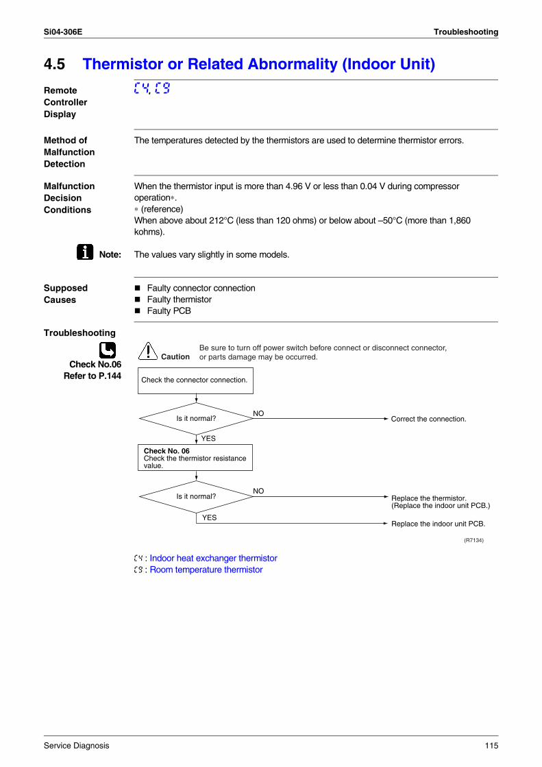
Si04-306E Troubleshooting
4.5 Thermistor or Related Abnormality (Indoor Unit)
Remote Controller Display
C4, C9
Method of Malfunction Detection
The temperatures detected by the thermistors are used to determine thermistor errors.
Malfunction Decision Conditions
When the thermistor input is more than 4.96 V or less than 0.04 V during compressor operation∗.∗ (reference)When above about 212°C (less than 120 ohms) or below about –50°C (more than 1,860 kohms).
Note: The values vary slightly in some models.
Supposed Causes
Faulty connector connectionFaulty thermistorFaulty PCB
Troubleshooting
Check No.06Refer to P.144
C4 : Indoor heat exchanger thermistorC9 : Room temperature thermistor
YES
(R7134)
NO
Check No. 06Check the thermistor resistance value.
YES
NO
CautionBe sure to turn off power switch before connect or disconnect connector, or parts damage may be occurred.
Correct the connection.
Replace the thermistor. (Replace the indoor unit PCB.)
Replace the indoor unit PCB.
Is it normal?
Is it normal?
Check the connector connection.
Service Diagnosis 115
Troubleshooting Si04-306E
4.6 Signal Transmission Error (between Indoor and Outdoor Units)
Remote Controller Display
U4
Method of Malfunction Detection
The data received from the outdoor unit in indoor unit-outdoor unit signal transmission is checked whether it is normal.
Malfunction Decision Conditions
When the data sent from the outdoor unit cannot be received normally, or when the content of the data is abnormal.
Supposed Causes
Faulty outdoor unit PCB.Faulty indoor unit PCB.Indoor unit-outdoor unit signal transmission error due to wiring error.Indoor unit-outdoor unit signal transmission error due to disturbed power supply waveform.Indoor unit-outdoor unit signal transmission error due to breaking of wire in the connection wires between the indoor and outdoor units (wire No. 3).Short circuit inside the fan motor winding
116 Service Diagnosis
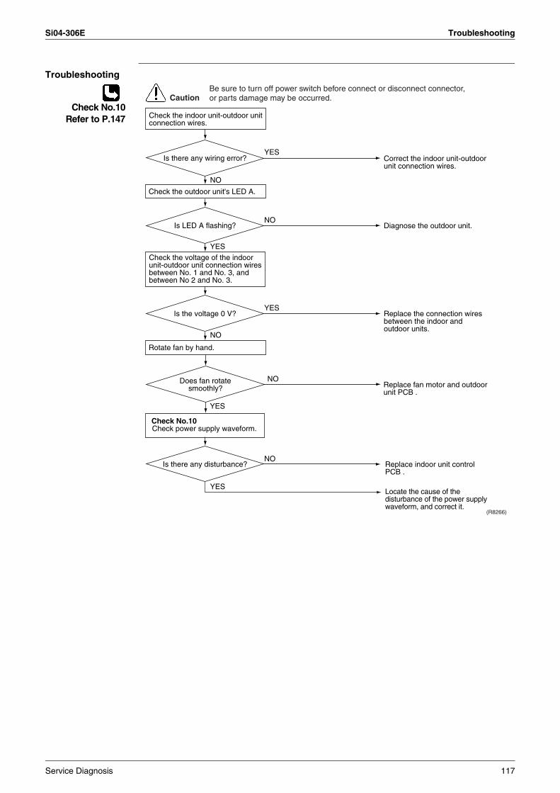
Si04-306E Troubleshooting
Troubleshooting
Check No.10Refer to P.147
Check the voltage of the indoor unit-outdoor unit connection wires between No. 1 and No. 3, and between No 2 and No. 3.
Check No.10Check power supply waveform.
YES
YES
Replace indoor unit control PCB .
Locate the cause of the disturbance of the power supply waveform, and correct it.
NO
(R8266)
NO
YES
YES
NO
NO
CautionBe sure to turn off power switch before connect or disconnect connector, or parts damage may be occurred.
YES
NO
Correct the indoor unit-outdoor unit connection wires.
Diagnose the outdoor unit.
Replace the connection wires between the indoor and outdoor units.
Replace fan motor and outdoor unit PCB .
Does fan rotate smoothly?
Is LED A flashing?
Is the voltage 0 V?
Is there any disturbance?
Is there any wiring error?
Check the indoor unit-outdoor unit connection wires.
Check the outdoor unit's LED A.
Rotate fan by hand.
Service Diagnosis 117
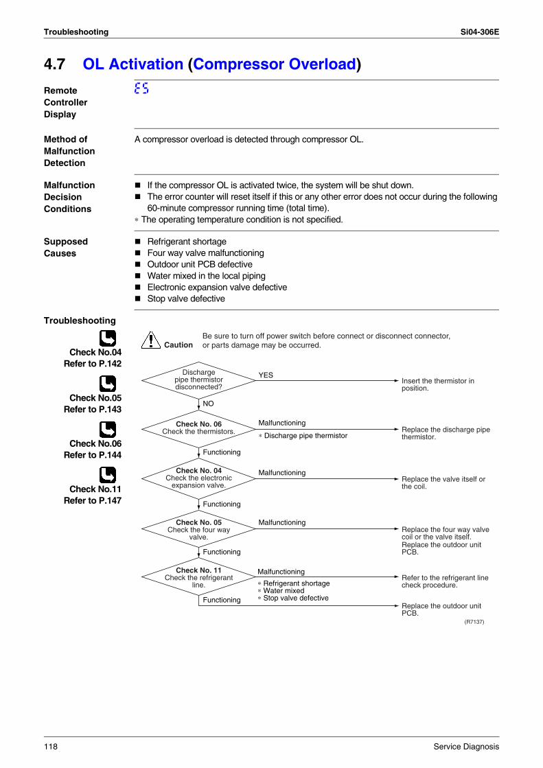
Troubleshooting Si04-306E
4.7 OL Activation (Compressor Overload)
Remote Controller Display
E5
Method of Malfunction Detection
A compressor overload is detected through compressor OL.
Malfunction Decision Conditions
If the compressor OL is activated twice, the system will be shut down.The error counter will reset itself if this or any other error does not occur during the following 60-minute compressor running time (total time).
∗ The operating temperature condition is not specified.
Supposed Causes
Refrigerant shortageFour way valve malfunctioningOutdoor unit PCB defectiveWater mixed in the local pipingElectronic expansion valve defectiveStop valve defective
Troubleshooting
Check No.04Refer to P.142
Check No.05Refer to P.143
Check No.06Refer to P.144
Check No.11Refer to P.147
(R7137)
CautionBe sure to turn off power switch before connect or disconnect connector, or parts damage may be occurred.
YES
Malfunctioning
∗ Discharge pipe thermistor
NO
Functioning
Functioning
Malfunctioning
∗ Refrigerant shortage∗ Water mixed∗ Stop valve defective
Malfunctioning
Functioning
Malfunctioning
Functioning
Insert the thermistor in position.
Replace the discharge pipe thermistor.
Replace the valve itself or the coil.
Refer to the refrigerant line check procedure.
Replace the outdoor unit PCB.
Replace the four way valve coil or the valve itself.Replace the outdoor unit PCB.
Discharge pipe thermistor disconnected?
Check No. 06Check the thermistors.
Check No. 05Check the four way
valve.
Check No. 11Check the refrigerant
line.
Check No. 04Check the electronic
expansion valve.
118 Service Diagnosis
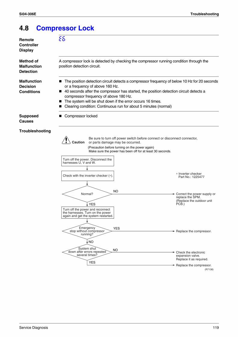
Si04-306E Troubleshooting
4.8 Compressor Lock
Remote Controller Display
E6
Method of Malfunction Detection
A compressor lock is detected by checking the compressor running condition through the position detection circuit.
Malfunction Decision Conditions
The position detection circuit detects a compressor frequency of below 10 Hz for 20 seconds or a frequency of above 160 Hz.40 seconds after the compressor has started, the position detection circuit detects a compressor frequency of above 180 Hz.The system will be shut down if the error occurs 16 times.Clearing condition: Continuous run for about 5 minutes (normal)
Supposed Causes
Compressor locked
Troubleshooting
Turn off the power. Disconnect the harnesses U, V and W.
(R7138)
CautionBe sure to turn off power switch before connect or disconnect connector, or parts damage may be occurred.
NO
YES
YES
NO
NO
YES
Check with the inverter checker (∗).
Turn off the power and reconnect the harnesses. Turn on the power again and get the system restarted.
(Precaution before turning on the power again) Make sure the power has been off for at least 30 seconds.
Correct the power supply or replace the SPM.(Replace the outdoor unit PCB.)
∗ Inverter checkerPart No.: 1225477
Replace the compressor.
Replace it as required.
Replace the compressor.
Check the electronic expansion valve.
Normal?
Emergency stop without compressor
running?
System shut down after errors repeated
several times?
Service Diagnosis 119
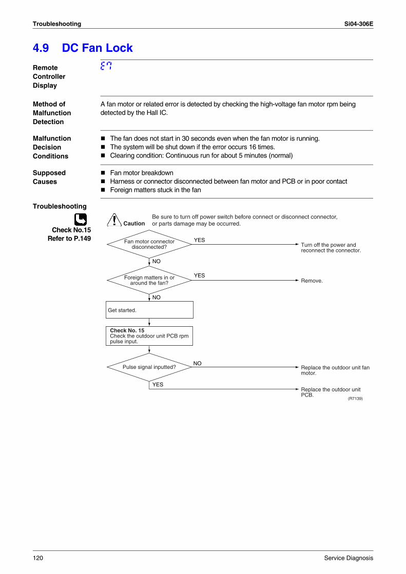
Troubleshooting Si04-306E
4.9 DC Fan Lock
Remote Controller Display
E7
Method of Malfunction Detection
A fan motor or related error is detected by checking the high-voltage fan motor rpm being detected by the Hall IC.
Malfunction Decision Conditions
The fan does not start in 30 seconds even when the fan motor is running.The system will be shut down if the error occurs 16 times.Clearing condition: Continuous run for about 5 minutes (normal)
Supposed Causes
Fan motor breakdownHarness or connector disconnected between fan motor and PCB or in poor contactForeign matters stuck in the fan
Troubleshooting
Check No.15Refer to P.149
(R7139)
CautionBe sure to turn off power switch before connect or disconnect connector, or parts damage may be occurred.
YES
YES
NO
YES
NO
NO
Get started.
Check No. 15Check the outdoor unit PCB rpm pulse input.
Turn off the power and reconnect the connector.
Remove.
Replace the outdoor unit fan motor.
Replace the outdoor unit PCB.
Fan motor connector disconnected?
Foreign matters in or around the fan?
Pulse signal inputted?
120 Service Diagnosis
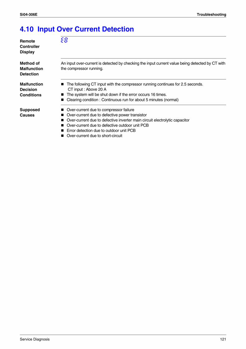
Si04-306E Troubleshooting
4.10 Input Over Current Detection
Remote Controller Display
E8
Method of Malfunction Detection
An input over-current is detected by checking the input current value being detected by CT with the compressor running.
Malfunction Decision Conditions
The following CT input with the compressor running continues for 2.5 seconds. CT input : Above 20 AThe system will be shut down if the error occurs 16 times.Clearing condition : Continuous run for about 5 minutes (normal)
Supposed Causes
Over-current due to compressor failureOver-current due to defective power transistorOver-current due to defective inverter main circuit electrolytic capacitorOver-current due to defective outdoor unit PCBError detection due to outdoor unit PCBOver-current due to short-circuit
Service Diagnosis 121
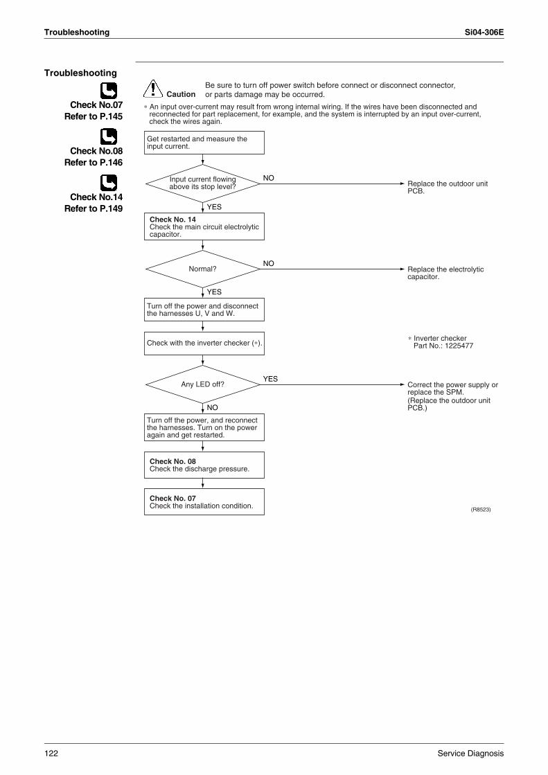
Troubleshooting Si04-306E
Troubleshooting
Check No.07Refer to P.145
Check No.08Refer to P.146
Check No.14Refer to P.149
(R8523)
CautionBe sure to turn off power switch before connect or disconnect connector, or parts damage may be occurred.
∗ An input over-current may result from wrong internal wiring. If the wires have been disconnected and reconnected for part replacement, for example, and the system is interrupted by an input over-current, check the wires again.
NO
YES
NO
YES
YES
NO
Get restarted and measure the input current.
Check No. 14Check the main circuit electrolytic capacitor.
Check No. 08Check the discharge pressure.
Check No. 07Check the installation condition.
Check with the inverter checker (∗).
Turn off the power and disconnect the harnesses U, V and W.
Turn off the power, and reconnect the harnesses. Turn on the power again and get restarted.
Replace the outdoor unit PCB.
Replace the electrolytic capacitor.
Correct the power supply or replace the SPM.(Replace the outdoor unit PCB.)
Normal?
Any LED off?
Input current flowing above its stop level?
∗ Inverter checkerPart No.: 1225477
122 Service Diagnosis
Si04-306E Troubleshooting
4.11 Four Way Valve Abnormality
Remote Controller Display
EA
Method of Malfunction Detection
The room temperature thermistor, the indoor unit heat exchanger thermistor, the outdoor temperature thermistor and the outdoor unit heat exchanger thermistor are checked to see if they function within their normal ranges in the operating mode.
Malfunction Decision Conditions
A following condition continues over 1 minute after operating 10 minutes.Cooling / dry operation(room temp. – indoor heat exchanger temp.) < –10°CHeating(indoor unit heat exchanger temp. – room temp.) < –10°C
Supposed Causes
Connector in poor contactThermistor defectiveOutdoor unit PCB defectiveFour way valve coil or harness defectiveFour way valve defectiveForeign substance mixed in refrigerantInsufficient gas
Service Diagnosis 123
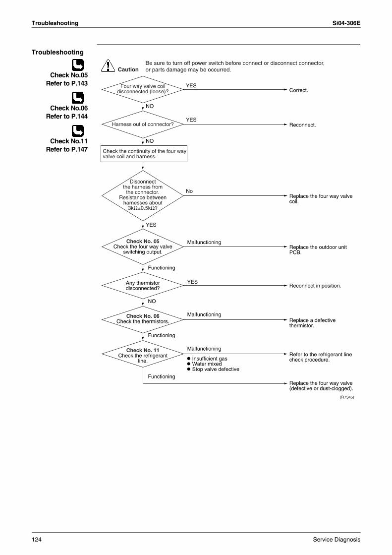
Troubleshooting Si04-306E
Troubleshooting
Check No.05Refer to P.143
Check No.06Refer to P.144
Check No.11Refer to P.147
Malfunctioning
Functioning
NO
Functioning
Malfunctioning
Functioning
YES
Malfunctioning
Correct.
Reconnect.
YES
YES
YES
NO
NO
Replace the four way valve coil.
No
Replace the outdoor unit PCB.
Insufficient gas Water mixed Stop valve defective
Replace a defective thermistor.
Refer to the refrigerant line check procedure.
Replace the four way valve (defective or dust-clogged).
Reconnect in position.
CautionBe sure to turn off power switch before connect or disconnect connector, or parts damage may be occurred.
(R7345)
Four way valve coil disconnected (loose)?
Harness out of connector?
Any thermistor disconnected?
Check No. 06Check the thermistors.
Check No. 11Check the refrigerant
line.
Check No. 05Check the four way valve
switching output.
Disconnect the harness from
the connector.Resistance between
harnesses about 3kΩ±0.5kΩ?
Check the continuity of the four way valve coil and harness.
124 Service Diagnosis
Si04-306E Troubleshooting
4.12 Discharge Pipe Temperature Control
Remote Controller Display
F3
Method of Malfunction Detection
The discharge pipe temperature control (stop, frequency drooping, etc.) is checked with the temperature being detected by the discharge pipe thermistor.
Malfunction Decision Conditions
If a stop takes place 6 times successively due to abnormal discharge pipe temperature, the system will be shut down.If the temperature being detected by the discharge pipe thermistor rises above 120°C, the compressor will stop. (The error is cleared when the temperature has dropped below 107°C.)
Stop temperatures (in case of 5.0kW class)(1) 110°C : above 45Hz (rising), above 40Hz (dropping)(2) 102°C : 30~45Hz (rising), 25~40Hz (dropping)(3) 98°C : below 30Hz (rising), below 25Hz (dropping)
The error counter will reset itself if this or any other error does not occur during the following 60-minute compressor running time (total time).
Supposed Causes
Refrigerant shortageFour way valve malfunctioningDischarge pipe thermistor defective(heat exchanger or outdoor temperature thermistor defective)Outdoor unit PCB defectiveWater mixed in the local pipingElectronic expansion valve defectiveStop valve defective
Troubleshooting
Check No.04Refer to P.142
Check No.06Refer to P.144
Check No.11Refer to P.147
(R7141)
CautionBe sure to turn off power switch before connect or disconnect connector, or parts damage may be occurred.
Malfunctioning
Discharge pipe thermistor Outdoor unit heat exchanger thermistor Outdoor temperature thermistor
Refrigerant shortage Four way valve malfunctioning Water mixed Stop valve defective
Functioning
Functioning
Functioning
Malfunctioning
Malfunctioning
Check No. 06Check the thermistors.
Check No. 11Check the refrigerant
line.
Check No. 04Check the electronic
expansion valve.
Replace the defective thermistor.
Replace the valve itself or the coil.
Refer to the refrigerant line check procedure.
Replace the outdoor unit PCB.
Service Diagnosis 125
Troubleshooting Si04-306E
4.13 High Pressure Control in Cooling
Remote Controller Display
F6
Method of Malfunction Detection
High-pressure control (stop, frequency drop, etc.) is activated in the cooling mode if the temperature being sensed by the heat exchanger thermistor exceeds the limit.
Malfunction Decision Conditions
Activated when the temperature being sensed by the heat exchanger thermistor rises above 60°C. (Deactivated when the said temperature drops below 50°C.)
Supposed Causes
The installation space is not large enough.Faulty outdoor unit fanFaulty electronic expansion valveFaulty defrost thermistorFaulty outdoor unit PCBFaulty stop valveDirty heat exchanger
126 Service Diagnosis
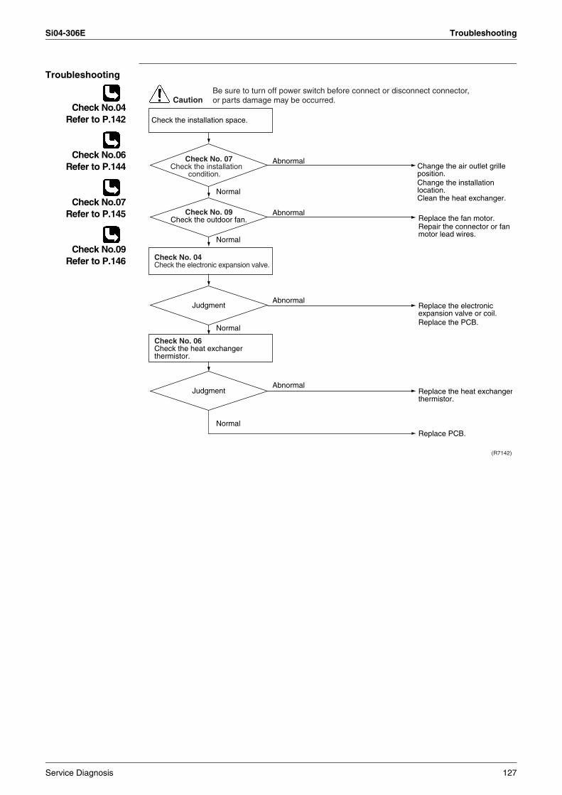
Si04-306E Troubleshooting
Troubleshooting
Check No.04Refer to P.142
Check No.06Refer to P.144
Check No.07Refer to P.145
Check No.09Refer to P.146
(R7142)
CautionBe sure to turn off power switch before connect or disconnect connector, or parts damage may be occurred.
Replace the fan motor.Repair the connector or fan motor lead wires.
Replace the heat exchangerthermistor.
Replace PCB.
Replace the electronic expansion valve or coil.Replace the PCB.
Change the air outlet grille position.
Clean the heat exchanger.
Change the installation location.
Check No. 06Check the heat exchanger thermistor.
Check the installation space.
Check No. 04Check the electronic expansion valve.
Abnormal
Normal
Normal
Normal
Normal
Abnormal
Abnormal
Abnormal
Judgment
Judgment
Check No. 09Check the outdoor fan.
Check No. 07Check the installation
condition.
Service Diagnosis 127
Troubleshooting Si04-306E
4.14 Position Sensor Abnormality
Remote Controller Display
H6
Method of Malfunction Detection
A compressor startup failure is detected by checking the compressor running condition through the position detection circuit.
Malfunction Decision Conditions
The compressor fails to start in about 15 seconds after the compressor run command signal is sent.Clearing condition: Continuous run for about 5 minutes (normal)The system will be shut down if the error occurs 16 times.
Supposed Causes
Compressor relay cable disconnectedCompressor itself defectiveOutdoor unit PCB defectiveStop valve closedInput voltage out of specification
Troubleshooting
Check No.13Refer to P.148
CautionBe sure to turn off power switch before connect or disconnect connector, or parts damage may be occurred.
(R7175)
NO
NO
NO
YES
YES
NO
YES
Check No. 13Check for short-circuit.
Check with the inverter checker (∗).
Turn off the power. Disconnect the harnesses U, V and W.
Check the electrolytic capacitor voltage.
Electricals or compressor harnesses
connected as specified?
Replace the outdoor unit PCB.
Replace the compressor.
Correct the power supply or replace the outdoor unit PCB.
Reconnect as specified.
Replace the outdoor unit PCB, outdoor unit fan.
∗ Inverter checkerPart No.: 1225477
Normal?
DC320±30V?
Any LED off?
128 Service Diagnosis
Si04-306E Troubleshooting
4.15 CT or Related Abnormality
Remote Controller Display
H8
Method of Malfunction Detection
A CT or related error is detected by checking the compressor running frequency and CT-detected input current.
Malfunction Decision Conditions
The compressor running frequency is below 55 Hz and the CT input is below 0.1 V.(The input current is also below 1.25 A.)
If this error repeats 4 times, the system will be shut down.The error counter will reset itself if this or any other error does not occur during the following 60-minute compressor running time (total time).
Supposed Causes
Power transistor defectiveInternal wiring broken or in poor contactReactor defectiveOutdoor unit PCB defective
Service Diagnosis 129
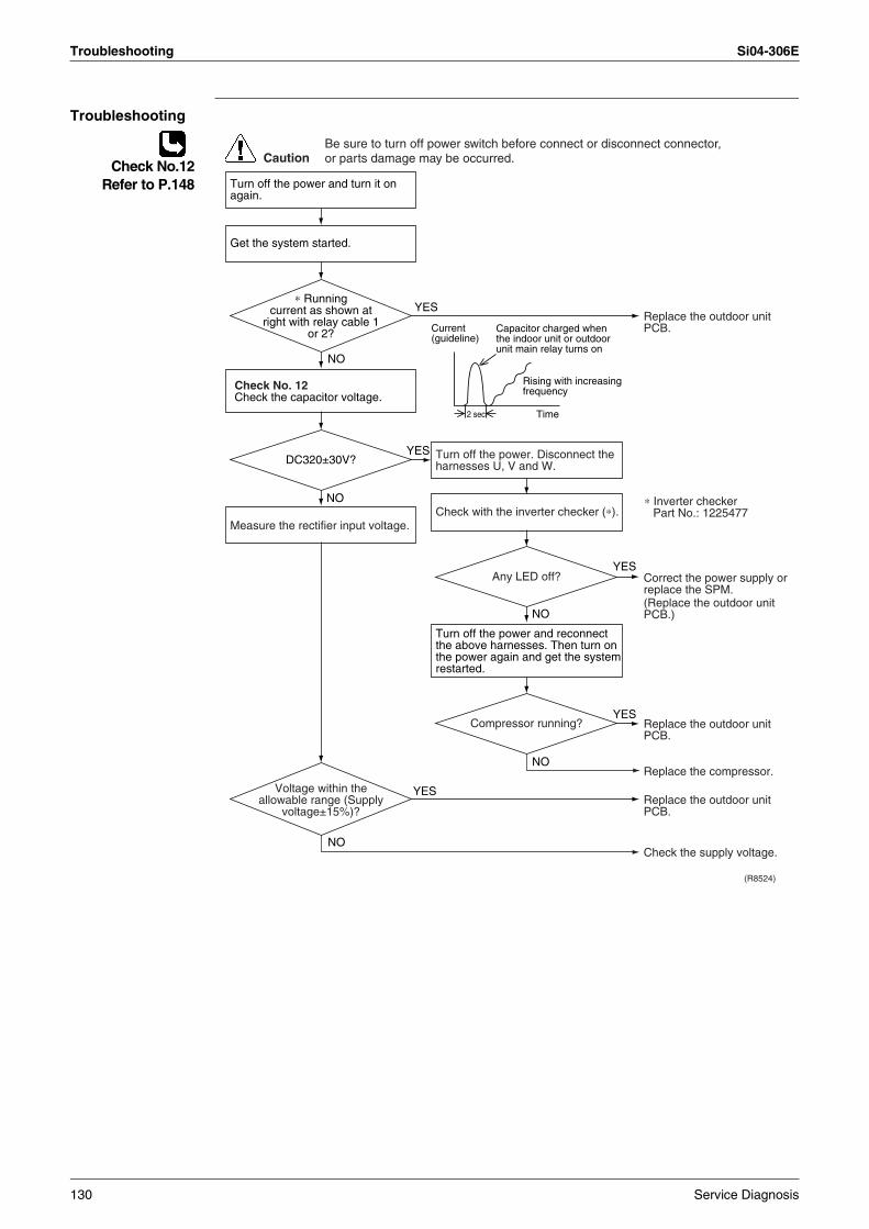
Troubleshooting Si04-306E
Troubleshooting
Check No.12Refer to P.148
(R8524)
CautionBe sure to turn off power switch before connect or disconnect connector, or parts damage may be occurred.
YES
Current (guideline)
2 sec Time
NO
NO
YES
YES
NO
YES
NO
YES
NO
Turn off the power and turn it on again.
Check No. 12Check the capacitor voltage.
Check with the inverter checker (∗).Measure the rectifier input voltage.
Get the system started.
Turn off the power. Disconnect the harnesses U, V and W.
Turn off the power and reconnect the above harnesses. Then turn on the power again and get the system restarted.
Compressor running?
DC320±30V?
Any LED off?
∗ Running current as shown at
right with relay cable 1 or 2?
Voltage within the allowable range (Supply
voltage±15%)?
Replace the outdoor unit PCB.
Replace the outdoor unit PCB.
Replace the outdoor unit PCB.
Check the supply voltage.
Replace the compressor.
Capacitor charged when the indoor unit or outdoor unit main relay turns on
Rising with increasing frequency
Correct the power supply or replace the SPM.(Replace the outdoor unit PCB.)
∗ Inverter checkerPart No.: 1225477
130 Service Diagnosis
Si04-306E Troubleshooting
4.16 Thermistor or Related Abnormality (Outdoor Unit)
Remote Controller Display
P4, J3, J6, H9
Method of Malfunction Detection
This type of error is detected by checking the thermistor input voltage to the microcomputer.[A thermistor error is detected by checking the temperature.]
Malfunction Decision Conditions
The thermistor input is above 4.96 V or below 0.04 V with the power on.Error J3 is judged if the discharge pipe thermistor temperature is smaller than the condenser thermistor temperature.
Supposed Causes
Connector in poor contactThermistor defectiveOutdoor unit PCB defectiveIndoor unit PCB defectiveCondenser thermistor defective in the case of J3 error (outdoor unit heat exchanger thermistor in the cooling mode, or indoor unit heat exchanger thermistor in the heating mode)
Service Diagnosis 131
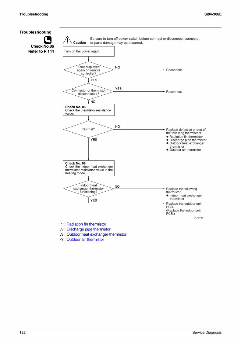
Troubleshooting Si04-306E
Troubleshooting
Check No.06Refer to P.144
P4 : Radiation fin thermistorJ3 : Discharge pipe thermistorJ6 : Outdoor heat exchanger thermistorH9 : Outdoor air thermistor
CautionBe sure to turn off power switch before connect or disconnect connector, or parts damage may be occurred.
(R7346)
NO
YES
YES
YES
NO
NO
NO
YES
Turn on the power again.
Normal?
Reconnect.
Reconnect.
Replace defective one(s) of the following thermistors.
Radiation fin thermistor Discharge pipe thermistor Outdoor heat exchanger thermistor
Outdoor air thermistor
Indoor heat exchanger thermistor
Replace the following thermistor.
Replace the outdoor unit PCB.(Replace the indoor unit PCB.)
Connector or thermistor disconnected?
Error displayed again on remote
controller?
Indoor heat exchanger thermistor
functioning?
Check No. 06Check the thermistor resistance value.
Check No. 06Check the indoor heat exchanger thermistor resistance value in the heating mode.
132 Service Diagnosis
Si04-306E Troubleshooting
4.17 Electrical Box Temperature Rise
Remote Controller Display
L3
Method of Malfunction Detection
An electrical box temperature rise is detected by checking the radiation fin thermistor with the compressor off.
Malfunction Decision Conditions
With the compressor off, the radiation fin temperature is above 80°C (above 75°C in the case of 7.1kW class). (Reset is made when the temperature drops below 70°C.)
Supposed Causes
Fin temperature rise due to defective outdoor unit fanFin temperature rise due to short-circuitFin thermistor defectiveConnector in poor contactOutdoor unit PCB defective
Service Diagnosis 133
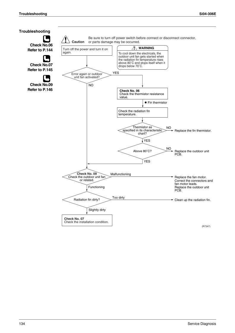
Troubleshooting Si04-306E
Troubleshooting
Check No.06Refer to P.144
Check No.07Refer to P.145
Check No.09Refer to P.146
CautionBe sure to turn off power switch before connect or disconnect connector, or parts damage may be occurred.
WARNING
To cool down the electricals, the outdoor unit fan gets started when the radiation fin temperature rises above 80˚C and stops itself when it drops below 70˚C.
(R7347)
YES
Fin thermistor
NO
Slightly dirty
Malfunctioning
Too dirty
Functioning
NO
YES
NO
YES
Turn off the power and turn it on again.
Check the radiation fin temperature.
Check No. 07Check the installation condition.
Radiation fin dirty?
Above 80˚C?
Thermistor as specified in its characteristic
chart?
Check No. 06Check the thermistor resistance value.
Check No. 09Check the outdoor unit fan
or related.
Error again or outdoor unit fan activated?
Replace the fin thermistor.
Replace the outdoor unit PCB.
Replace the outdoor unit PCB.
Replace the fan motor.Correct the connectors and fan motor leads.
Clean up the radiation fin.
134 Service Diagnosis
Si04-306E Troubleshooting
4.18 Radiation Fin Temperature Rise
Remote Controller Display
L4
Method of Malfunction Detection
A radiation fin temperature rise is detected by checking the radiation fin thermistor with the compressor on.
Malfunction Decision Conditions
If the radiation fin temperature with the compressor on is above 90°C,If a radiation fin temperature rise takes place 4 times successively, the system will be shut down.The error counter will reset itself if this or any other error does not occur during the following 60-minute compressor running time (total time).
Supposed Causes
Fin temperature rise due to defective outdoor unit fanFin temperature rise due to short-circuitFin thermistor defectiveConnector in poor contactOutdoor unit PCB defectiveSilicon grease is not applied properly on the heat radiation fin after replacing outdoor unit PCB
Service Diagnosis 135
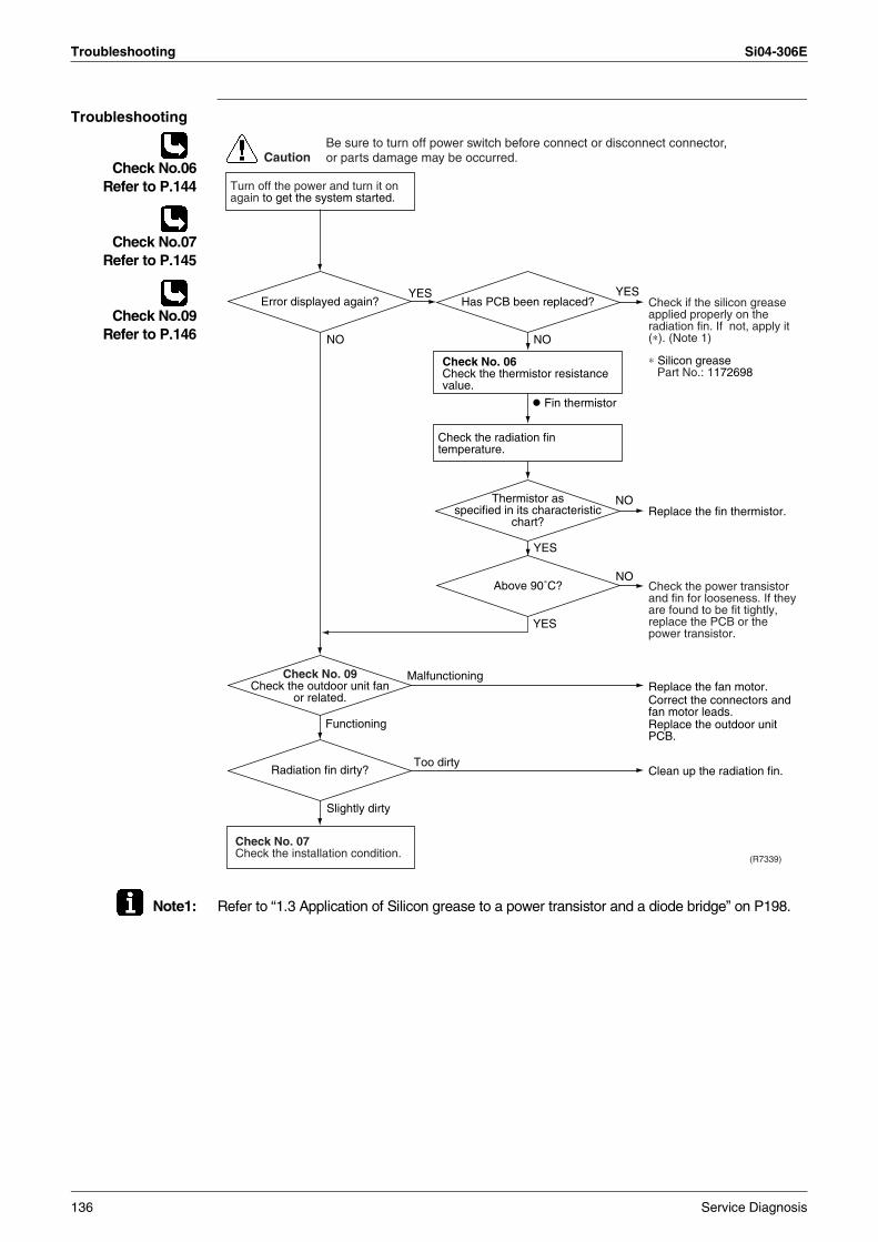
Troubleshooting Si04-306E
Troubleshooting
Check No.06Refer to P.144
Check No.07Refer to P.145
Check No.09Refer to P.146
Note1: Refer to “1.3 Application of Silicon grease to a power transistor and a diode bridge” on P198.
(R7339)
CautionBe sure to turn off power switch before connect or disconnect connector, or parts damage may be occurred.
NO
Slightly dirty
Malfunctioning
Too dirty
Functioning
NO
YES
NO
YES
Fin thermistor
Turn off the power and turn it on again to get the system started.
Check the radiation fin temperature.
Check No. 07Check the installation condition.
NO
YESYES
Radiation fin dirty?
Above 90˚C?
Thermistor as specified in its characteristic
chart?
Check No. 06Check the thermistor resistance value.
Check No. 09Check the outdoor unit fan
or related.
Error displayed again? Has PCB been replaced?
Replace the fin thermistor.
Check if the silicon grease applied properly on the radiation fin. If not, apply it (∗). (Note 1)
Check the power transistor and fin for looseness. If they are found to be fit tightly, replace the PCB or the power transistor.
Replace the outdoor unit PCB.
Replace the fan motor.Correct the connectors and fan motor leads.
Clean up the radiation fin.
∗ Silicon greasePart No.: 1172698
136 Service Diagnosis
Si04-306E Troubleshooting
4.19 Output Over Current Detection
Remote Controller Display
L5
Method of Malfunction Detection
An output over-current is detected by checking the current that flows in the inverter DC section.
Malfunction Decision Conditions
A position signal error occurs while the compressor is running.A speed error occurs while the compressor is running.An output over-current input is fed from the output over-current detection circuit to the microcomputer.The system will be shut down if the error occurs 16 times.Clearing condition: Continuous run for about 5 minutes (normal)
Supposed Causes
Over-current due to defective power transistorOver-current due to wrong internal wiringOver-current due to abnormal supply voltageOver-current due to defective PCBError detection due to defective PCBOver-current due to closed stop valveOver-current due to compressor failureOver-current due to poor installation condition
Service Diagnosis 137
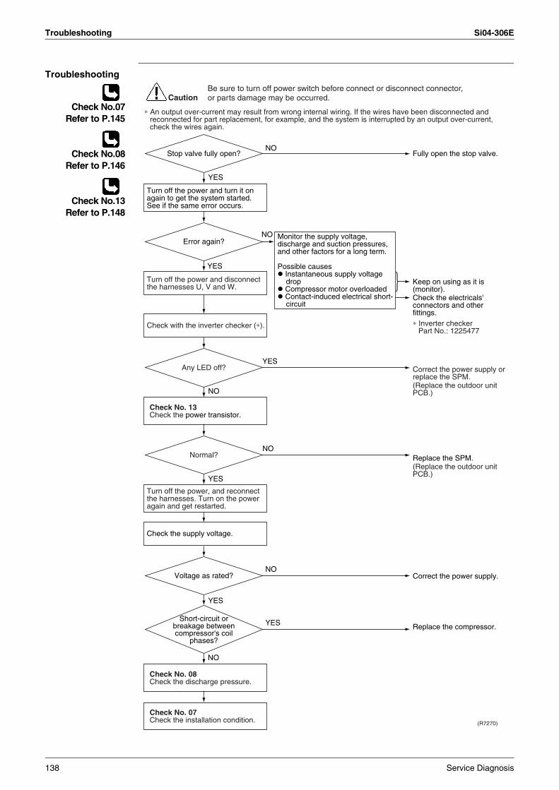
Troubleshooting Si04-306E
Troubleshooting
Check No.07Refer to P.145
Check No.08Refer to P.146
Check No.13Refer to P.148
(R7270)
CautionBe sure to turn off power switch before connect or disconnect connector, or parts damage may be occurred.
NO
YES
NO
YES
NO
YES
YES
NO
NO
YES
YES
NO
Monitor the supply voltage, discharge and suction pressures, and other factors for a long term.
Possible causes Instantaneous supply voltage drop
Compressor motor overloaded Contact-induced electrical short-circuit
∗ An output over-current may result from wrong internal wiring. If the wires have been disconnected and reconnected for part replacement, for example, and the system is interrupted by an output over-current, check the wires again.
Check No. 08Check the discharge pressure.
Check No. 13Check the power transistor.
Check No. 07Check the installation condition.
Check with the inverter checker (∗).
Turn off the power and disconnect the harnesses U, V and W.
Turn off the power, and reconnect the harnesses. Turn on the power again and get restarted.
Turn off the power and turn it on again to get the system started. See if the same error occurs.
Check the supply voltage.
Keep on using as it is (monitor).Check the electricals' connectors and other fittings.
Fully open the stop valve.
Correct the power supply.
Replace the compressor.
Correct the power supply or replace the SPM.(Replace the outdoor unit PCB.)
Replace the SPM.(Replace the outdoor unit PCB.)
Normal?
Error again?
Stop valve fully open?
Voltage as rated?
Any LED off?
∗ Inverter checkerPart No.: 1225477
Short-circuit or breakage between compressor's coil
phases?
138 Service Diagnosis
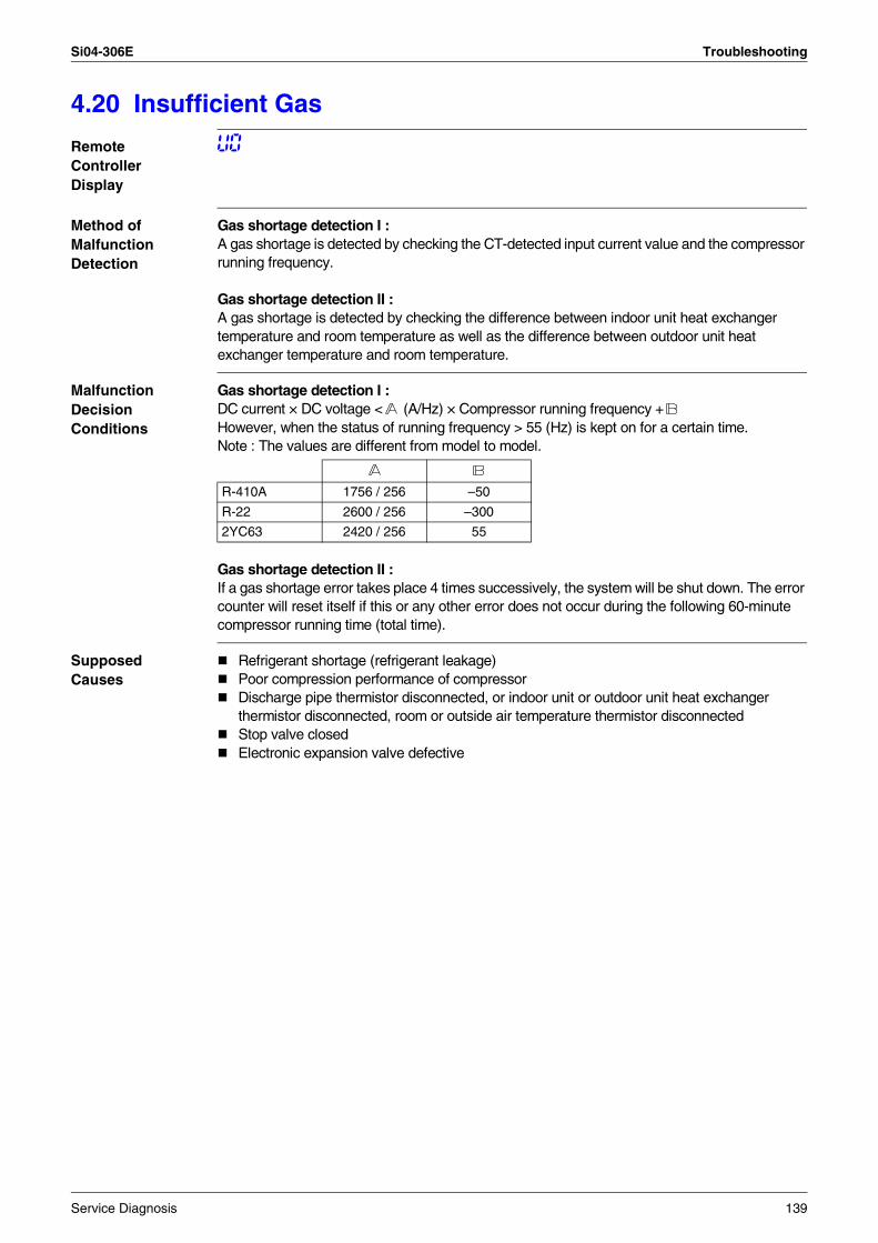
Si04-306E Troubleshooting
4.20 Insufficient Gas
Remote Controller Display
U0
Method of Malfunction Detection
Gas shortage detection I : A gas shortage is detected by checking the CT-detected input current value and the compressor running frequency.
Gas shortage detection II : A gas shortage is detected by checking the difference between indoor unit heat exchanger temperature and room temperature as well as the difference between outdoor unit heat exchanger temperature and room temperature.
Malfunction Decision Conditions
Gas shortage detection I : DC current × DC voltage < (A/Hz) × Compressor running frequency +However, when the status of running frequency > 55 (Hz) is kept on for a certain time.Note : The values are different from model to model.
Gas shortage detection II : If a gas shortage error takes place 4 times successively, the system will be shut down. The error counter will reset itself if this or any other error does not occur during the following 60-minute compressor running time (total time).
Supposed Causes
Refrigerant shortage (refrigerant leakage)Poor compression performance of compressorDischarge pipe thermistor disconnected, or indoor unit or outdoor unit heat exchanger thermistor disconnected, room or outside air temperature thermistor disconnectedStop valve closedElectronic expansion valve defective
R-410A 1756 / 256 –50
R-22 2600 / 256 –300
2YC63 2420 / 256 55
Service Diagnosis 139
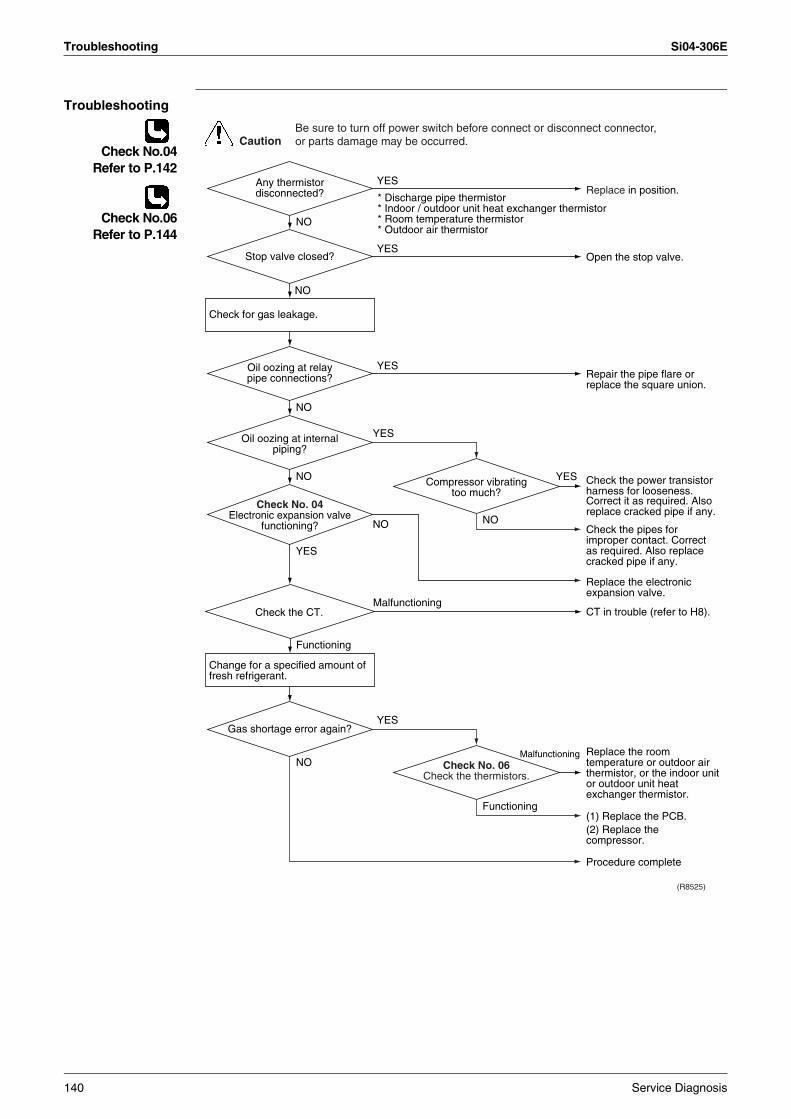
Troubleshooting Si04-306E
Troubleshooting
Check No.04Refer to P.142
Check No.06Refer to P.144
(R8525)
CautionBe sure to turn off power switch before connect or disconnect connector, or parts damage may be occurred.
YES
Malfunctioning
NO
NO
YES
YES
YES
NO
Functioning
YES
NO
NO
YES
NO
NO
YES
* Discharge pipe thermistor* Indoor / outdoor unit heat exchanger thermistor* Room temperature thermistor* Outdoor air thermistor
Check for gas leakage.
Change for a specified amount of fresh refrigerant.
Check No. 04Electronic expansion valve
functioning?
Replace in position.
Open the stop valve.
Repair the pipe flare or replace the square union.
Check the power transistor harness for looseness.Correct it as required. Also replace cracked pipe if any.
Check the pipes for improper contact. Correct as required. Also replace cracked pipe if any.
Replace the electronic expansion valve.
CT in trouble (refer to H8).
Replace the room temperature or outdoor air thermistor, or the indoor unit or outdoor unit heat exchanger thermistor.
(1) Replace the PCB.(2) Replace the compressor.
Procedure complete
Gas shortage error again?
Oil oozing at internal piping?
Stop valve closed?
Compressor vibrating too much?
Oil oozing at relay pipe connections?
Any thermistor disconnected?
Check No. 06Check the thermistors.
Malfunctioning
Functioning
Check the CT.
140 Service Diagnosis
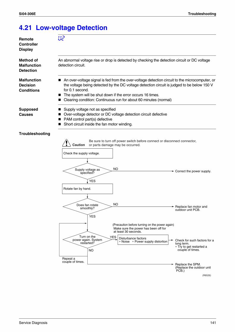
Si04-306E Troubleshooting
4.21 Low-voltage Detection
Remote Controller Display
U2
Method of Malfunction Detection
An abnormal voltage rise or drop is detected by checking the detection circuit or DC voltage detection circuit.
Malfunction Decision Conditions
An over-voltage signal is fed from the over-voltage detection circuit to the microcomputer, or the voltage being detected by the DC voltage detection circuit is judged to be below 150 V for 0.1 second.The system will be shut down if the error occurs 16 times.Clearing condition: Continuous run for about 60 minutes (normal)
Supposed Causes
Supply voltage not as specifiedOver-voltage detector or DC voltage detection circuit defectivePAM control part(s) defectiveShort circuit inside the fan motor winding.
Troubleshooting
Correct the power supply.
Replace the SPM.
Check for such factors for a long term.∗ Try to get restarted a
couple of times.
(R8526)
CautionBe sure to turn off power switch before connect or disconnect connector, or parts damage may be occurred.
NO
YES
YES
NO
YES
(Precaution before turning on the power again)
NOReplace fan motor and outdoor unit PCB.
(Replace the outdoor unit PCB.)
Check the supply voltage.
Rotate fan by hand.
Disturbance factors ∗ Noise ∗ Power supply distortion
Repeat a couple of times.
Make sure the power has been off for at least 30 seconds.
Turn on the power again. System
restarted?
Does fan rotate smoothly?
Supply voltage as specified?
Service Diagnosis 141
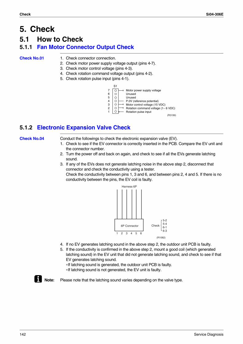
Check Si04-306E
5. Check5.1 How to Check5.1.1 Fan Motor Connector Output Check
Check No.01 1. Check connector connection.2. Check motor power supply voltage output (pins 4-7).3. Check motor control voltage (pins 4-3).4. Check rotation command voltage output (pins 4-2).5. Check rotation pulse input (pins 4-1).
5.1.2 Electronic Expansion Valve Check
Check No.04 Conduct the followings to check the electronic expansion valve (EV).1. Check to see if the EV connector is correctly inserted in the PCB. Compare the EV unit and
the connector number.2. Turn the power off and back on again, and check to see if all the EVs generate latching
sound.3. If any of the EVs does not generate latching noise in the above step 2, disconnect that
connector and check the conductivity using a tester.Check the conductivity between pins 1, 3 and 6, and between pins 2, 4 and 5. If there is no conductivity between the pins, the EV coil is faulty.
4. If no EV generates latching sound in the above step 2, the outdoor unit PCB is faulty.5. If the conductivity is confirmed in the above step 2, mount a good coil (which generated
latching sound) in the EV unit that did not generate latching sound, and check to see if that EV generates latching sound.∗If latching sound is generated, the outdoor unit PCB is faulty.∗If latching sound is not generated, the EV unit is faulty.
Note: Please note that the latching sound varies depending on the valve type.
7654321
Motor power supply voltageUnusedUnusedP.0V (reference potential)Motor control voltage (15 VDC)Rotation command voltage (1~ 6 VDC)Rotation pulse input
S1
(R3199)
Harness 6P
6P Connector Check
5-25-46-16-3
1 2 3 4 5 6(R1082)
142 Service Diagnosis
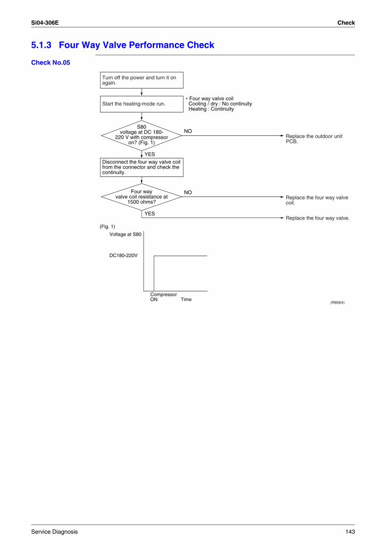
Si04-306E Check
5.1.3 Four Way Valve Performance Check
Check No.05
(R8564)
NO
YES
YES
NO
(Fig. 1)
Voltage at S80
DC180-220V
ONCompressor
Time
Turn off the power and turn it on again.
Disconnect the four way valve coil from the connector and check the continuity.
Start the heating-mode run.∗ Four way valve coil
Cooling / dry : No continuity Heating : Continuity
Replace the outdoor unit PCB.
Replace the four way valve coil.
Replace the four way valve.
Four way valve coil resistance at
1500 ohms?
S80 voltage at DC 180-
220 V with compressor on? (Fig. 1)
Service Diagnosis 143
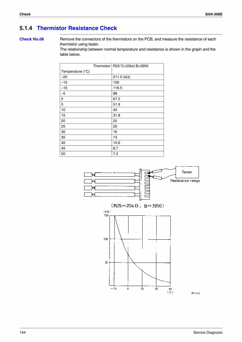
Check Si04-306E
5.1.4 Thermistor Resistance Check
Check No.06 Remove the connectors of the thermistors on the PCB, and measure the resistance of each thermistor using tester.The relationship between normal temperature and resistance is shown in the graph and the table below.
Thermistor R25°C=20kΩ B=3950
Temperature (°C)
–20 211.0 (kΩ)
–15 150
–10 116.5
–5 88
0 67.2
5 51.9
10 40
15 31.8
20 25
25 20
30 16
35 13
40 10.6
45 8.7
50 7.2
144 Service Diagnosis
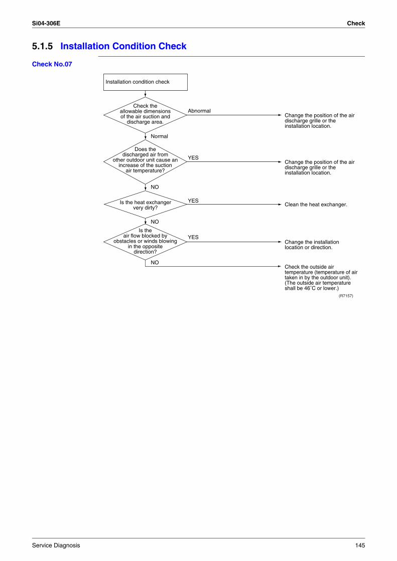
Si04-306E Check
5.1.5 Installation Condition Check
Check No.07
Installation condition check
Normal
(R7157)
Abnormal
YES
YES
YES
NO
NO
NO
Is the heat exchanger very dirty?
Check the allowable dimensions of the air suction and
discharge area.
Is the air flow blocked by
obstacles or winds blowing in the opposite
direction?
Does the discharged air from
other outdoor unit cause an increase of the suction
air temperature?
Change the position of the air discharge grille or the installation location.
Change the position of the air discharge grille or the installation location.
Change the installation location or direction.
Check the outside air temperature (temperature of air taken in by the outdoor unit). (The outside air temperature shall be 46˚C or lower.)
Clean the heat exchanger.
Service Diagnosis 145
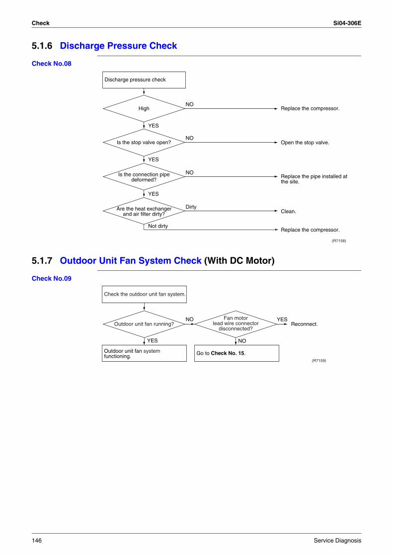
Check Si04-306E
5.1.6 Discharge Pressure Check
Check No.08
5.1.7 Outdoor Unit Fan System Check (With DC Motor)
Check No.09
(R7158)
Not dirty
YES
YES
Dirty
NO
NO
NO
YES
Are the heat exchanger and air filter dirty?
Is the connection pipe deformed?
Is the stop valve open?
High Replace the compressor.
Open the stop valve.
Replace the pipe installed at the site.
Clean.
Replace the compressor.
Discharge pressure check
(R7159)
YES
YESNO
NO
Outdoor unit fan system functioning.
Check the outdoor unit fan system.
Go to Check No. 15.
Outdoor unit fan running?Fan motor
lead wire connector disconnected?
Reconnect.
146 Service Diagnosis
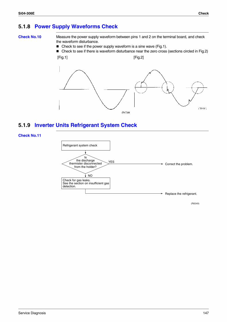
Si04-306E Check
5.1.8 Power Supply Waveforms Check
Check No.10 Measure the power supply waveform between pins 1 and 2 on the terminal board, and check the waveform disturbance.
Check to see if the power supply waveform is a sine wave (Fig.1).Check to see if there is waveform disturbance near the zero cross (sections circled in Fig.2)
5.1.9 Inverter Units Refrigerant System Check
Check No.11
[Fig.1] [Fig.2]
Refrigerant system check
Check for gas leaks.See the section on insufficient gas detection.
(R8349)
YES
NO
Correct the problem.
Replace the refrigerant.
Is the discharge
thermister disconnected from the holder?
Service Diagnosis 147
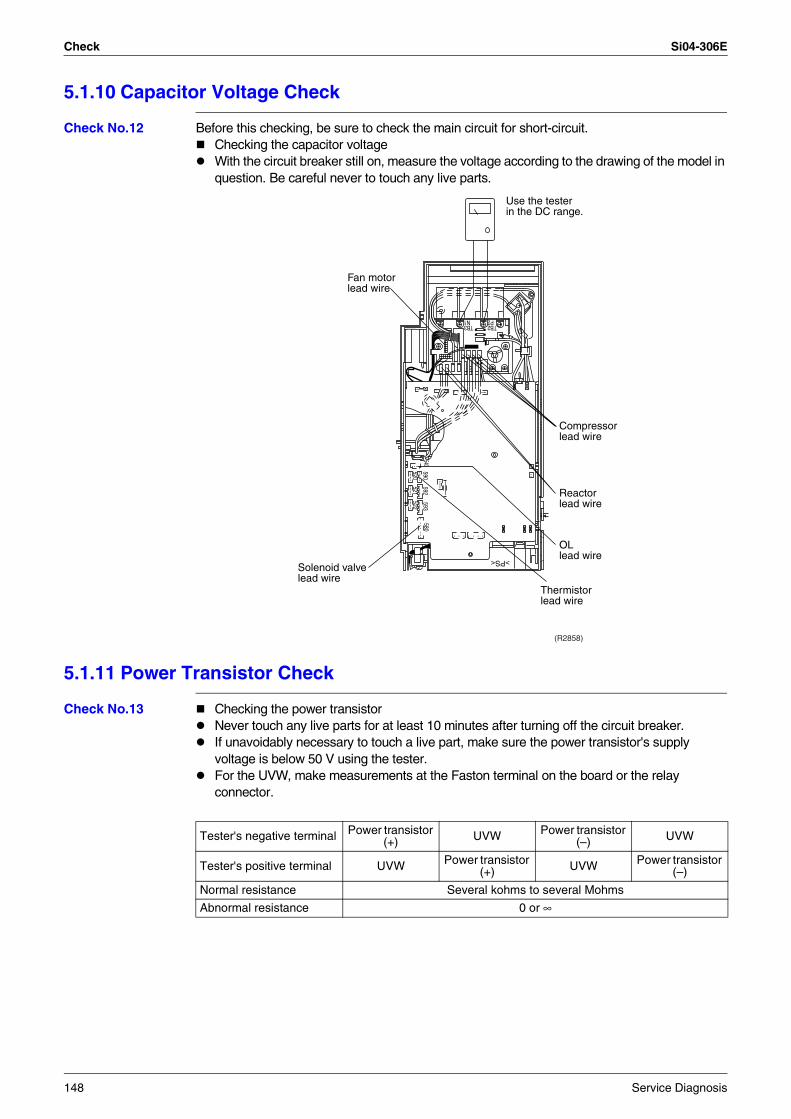
Check Si04-306E
5.1.10 Capacitor Voltage Check
Check No.12 Before this checking, be sure to check the main circuit for short-circuit.Checking the capacitor voltageWith the circuit breaker still on, measure the voltage according to the drawing of the model in question. Be careful never to touch any live parts.
5.1.11 Power Transistor Check
Check No.13 Checking the power transistorNever touch any live parts for at least 10 minutes after turning off the circuit breaker.If unavoidably necessary to touch a live part, make sure the power transistor's supply voltage is below 50 V using the tester.For the UVW, make measurements at the Faston terminal on the board or the relay connector.
Fan motorlead wire
Solenoid valvelead wire
Thermistorlead wire
OLlead wire
Reactor lead wire
Compressorlead wire
TB2
>PS<
TB3P2N1
590592
593580
520521
522
540
(R2858)
Use the testerin the DC range.
Tester's negative terminal Power transistor (+) UVW Power transistor
(–) UVW
Tester's positive terminal UVW Power transistor (+) UVW Power transistor
(–)
Normal resistance Several kohms to several Mohms
Abnormal resistance 0 or ∞
148 Service Diagnosis
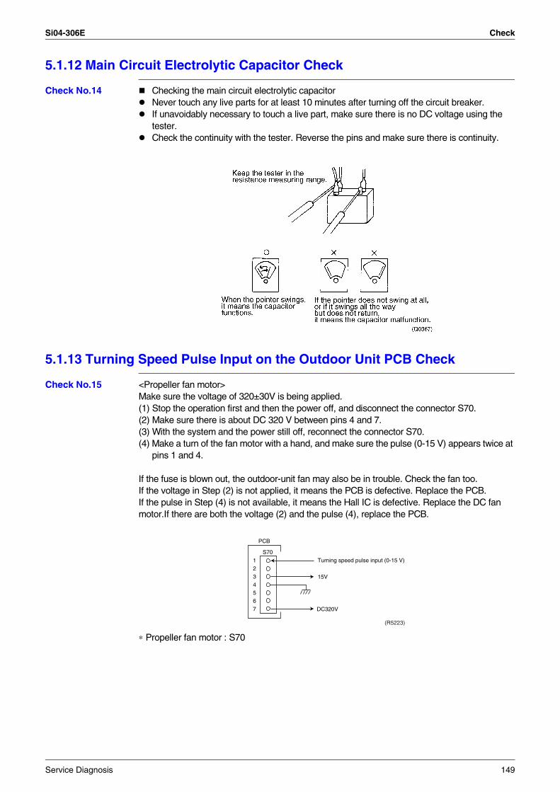
Si04-306E Check
5.1.12 Main Circuit Electrolytic Capacitor Check
Check No.14 Checking the main circuit electrolytic capacitorNever touch any live parts for at least 10 minutes after turning off the circuit breaker.If unavoidably necessary to touch a live part, make sure there is no DC voltage using the tester.Check the continuity with the tester. Reverse the pins and make sure there is continuity.
5.1.13 Turning Speed Pulse Input on the Outdoor Unit PCB Check
Check No.15 <Propeller fan motor>Make sure the voltage of 320±30V is being applied.(1) Stop the operation first and then the power off, and disconnect the connector S70.(2) Make sure there is about DC 320 V between pins 4 and 7.(3) With the system and the power still off, reconnect the connector S70.(4) Make a turn of the fan motor with a hand, and make sure the pulse (0-15 V) appears twice at
pins 1 and 4.
If the fuse is blown out, the outdoor-unit fan may also be in trouble. Check the fan too.If the voltage in Step (2) is not applied, it means the PCB is defective. Replace the PCB.If the pulse in Step (4) is not available, it means the Hall IC is defective. Replace the DC fan motor.If there are both the voltage (2) and the pulse (4), replace the PCB.
∗ Propeller fan motor : S70
1234567 DC320V
S70
PCB
Turning speed pulse input (0-15 V)
15V
(R5223)
Service Diagnosis 149
Check Si04-306E
150 Service Diagnosis
Si04-306E
Removal Procedure 151
Part 7Removal Procedure
1. Indoor Unit...........................................................................................1521.1 Removal of the Air Filter / Front Panel .................................................1521.2 Removal of the Front Grille ..................................................................1551.3 Removal of the Horizontal Blades / Vertical Blades .............................1571.4 Removal of the Electrical Box / PCB / Swing Motor .............................1591.5 Removal of the Heat Exchanger ..........................................................1651.6 Removal of the Fan Rotor / Fan Motor.................................................168
2. Outdoor Unit........................................................................................1702.1 Removal of the Panels and Plates .......................................................1702.2 Removal of the Fan Motor / Propeller Fan ...........................................1742.3 Removal of the PCB / Electrical Box ....................................................1782.4 Removal of the Reactor........................................................................1862.5 Removal of the Sound Blanket.............................................................1882.6 Removal of the Four Way Valve...........................................................1902.7 Removal of the Electronic Expansion Valve.........................................1912.8 Removal of the Compressor.................................................................192
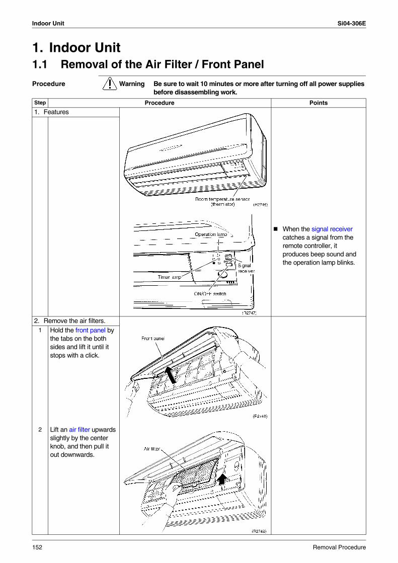
Indoor Unit Si04-306E
1. Indoor Unit1.1 Removal of the Air Filter / Front Panel
Procedure Warning Be sure to wait 10 minutes or more after turning off all power supplies before disassembling work.
Step Procedure Points
1. Features
When the signal receiver catches a signal from the remote controller, it produces beep sound and the operation lamp blinks.
2. Remove the air filters.1 Hold the front panel by
the tabs on the both sides and lift it until it stops with a click.
2 Lift an air filter upwards slightly by the center knob, and then pull it out downwards.
152 Removal Procedure
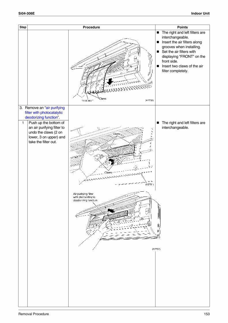
Si04-306E Indoor Unit
The right and left filters are interchangeable.Insert the air filters along grooves when installing.Set the air filters with displaying “FRONT” on the front side.Insert two claws of the air filter completely.
3. Remove an “air purifying filter with photocatalytic deodorizing function”.
1 Push up the bottom of an air purifying filter to undo the claws (2 on lower, 3 on upper) and take the filter out.
The right and left filters are interchangeable.
Step Procedure Points
Removal Procedure 153
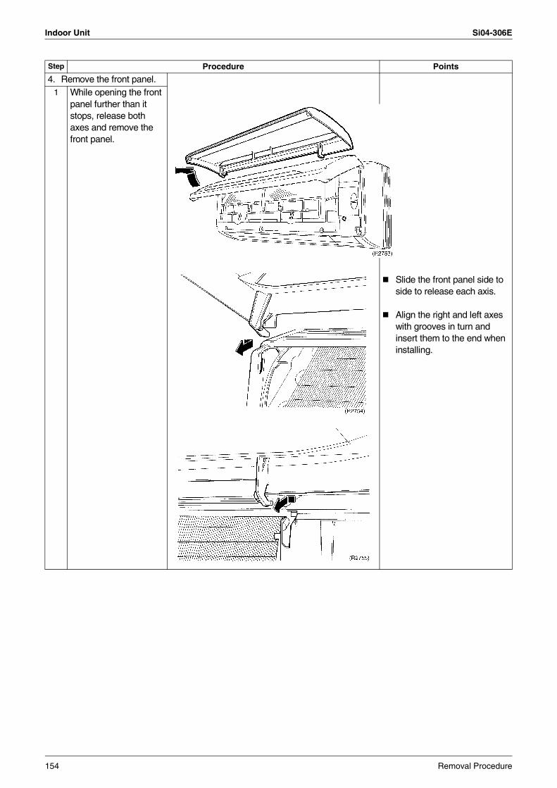
Indoor Unit Si04-306E
4. Remove the front panel.1 While opening the front
panel further than it stops, release both axes and remove the front panel.
Slide the front panel side to side to release each axis.
Align the right and left axes with grooves in turn and insert them to the end when installing.
Step Procedure Points
154 Removal Procedure
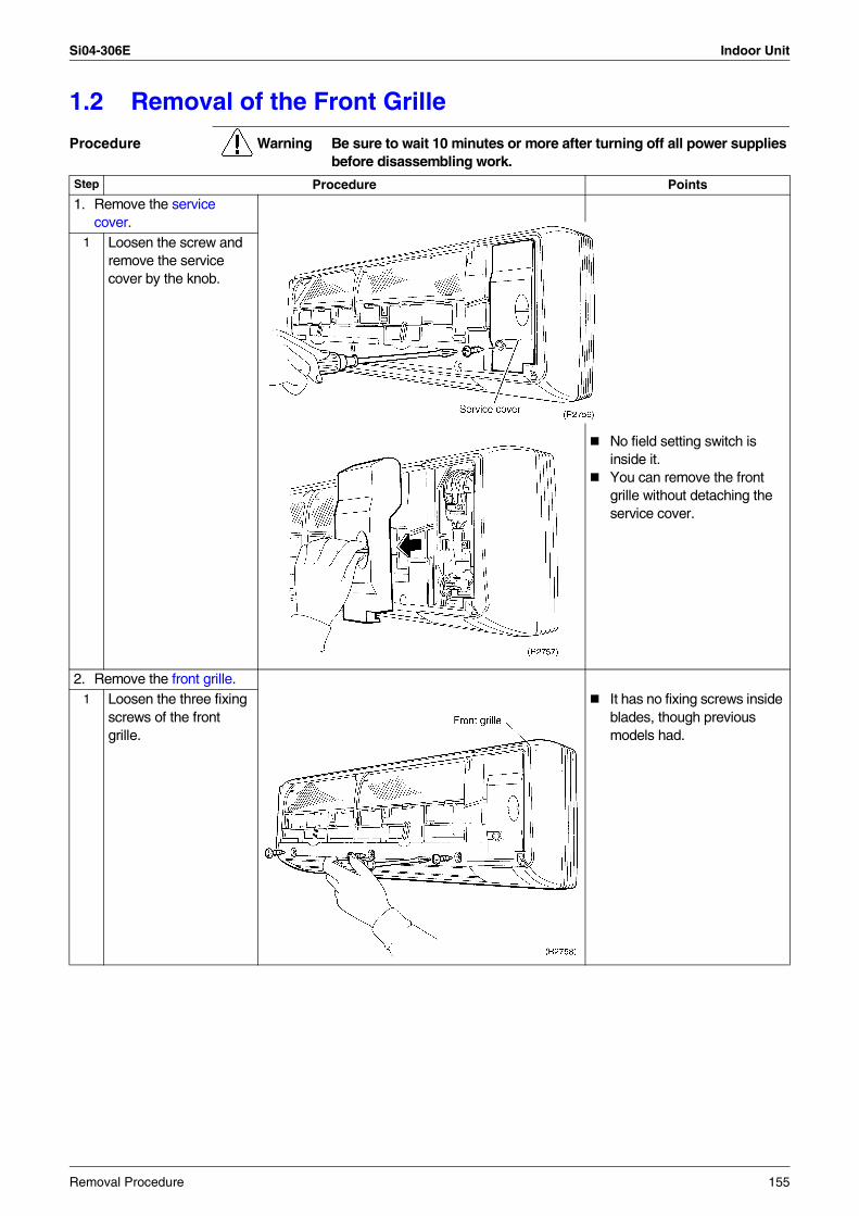
Si04-306E Indoor Unit
1.2 Removal of the Front Grille
Procedure Warning Be sure to wait 10 minutes or more after turning off all power supplies before disassembling work.
Step Procedure Points
1. Remove the service cover.
1 Loosen the screw and remove the service cover by the knob.
No field setting switch is inside it. You can remove the front grille without detaching the service cover.
2. Remove the front grille.1 Loosen the three fixing
screws of the front grille.
It has no fixing screws inside blades, though previous models had.
Removal Procedure 155
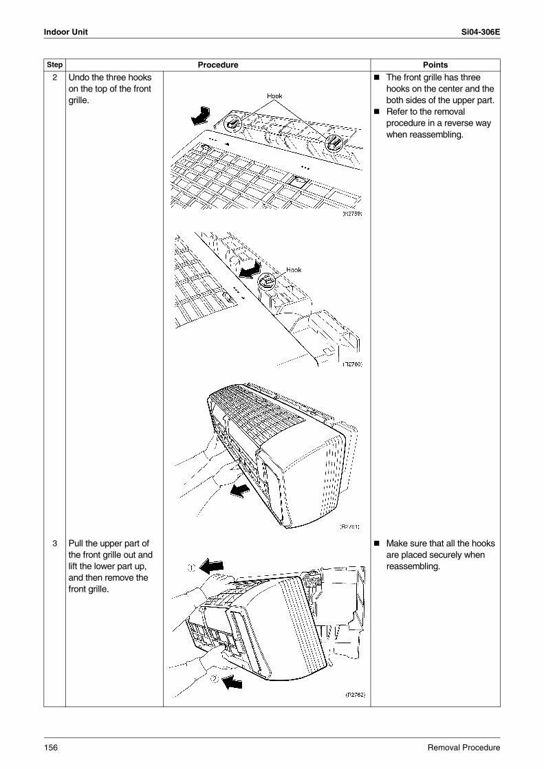
Indoor Unit Si04-306E
2 Undo the three hooks on the top of the front grille.
The front grille has three hooks on the center and the both sides of the upper part.Refer to the removal procedure in a reverse way when reassembling.
3 Pull the upper part of the front grille out and lift the lower part up, and then remove the front grille.
Make sure that all the hooks are placed securely when reassembling.
Step Procedure Points
156 Removal Procedure
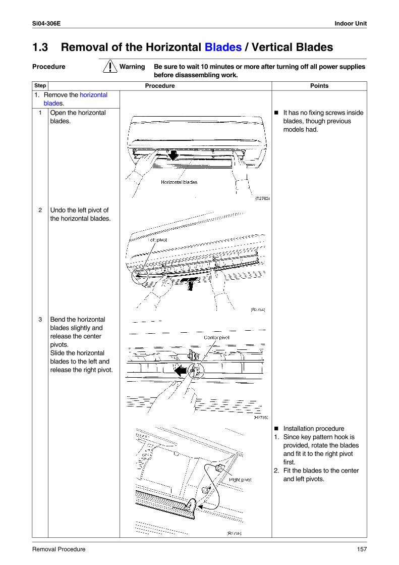
Si04-306E Indoor Unit
1.3 Removal of the Horizontal Blades / Vertical Blades
Procedure Warning Be sure to wait 10 minutes or more after turning off all power supplies before disassembling work.
Step Procedure Points
1. Remove the horizontal blades.
1 Open the horizontal blades.
It has no fixing screws inside blades, though previous models had.
2 Undo the left pivot of the horizontal blades.
3 Bend the horizontal blades slightly and release the center pivots. Slide the horizontal blades to the left and release the right pivot.
Installation procedure1. Since key pattern hook is
provided, rotate the blades and fit it to the right pivot first.
2. Fit the blades to the center and left pivots.
Removal Procedure 157
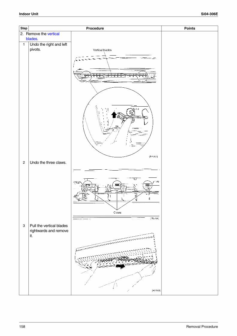
Indoor Unit Si04-306E
2. Remove the vertical blades.
1 Undo the right and left pivots.
2 Undo the three claws.
3 Pull the vertical blades rightwards and remove it.
Step Procedure Points
158 Removal Procedure
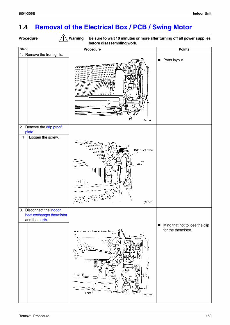
Si04-306E Indoor Unit
1.4 Removal of the Electrical Box / PCB / Swing Motor
Procedure Warning Be sure to wait 10 minutes or more after turning off all power supplies before disassembling work.
Step Procedure Points
1. Remove the front grille.Parts layout
2. Remove the drip proof plate.
1 Loosen the screw.
3. Disconnect the indoor heat exchanger thermistor and the earth.
Mind that not to lose the clip for the thermistor.
Removal Procedure 159
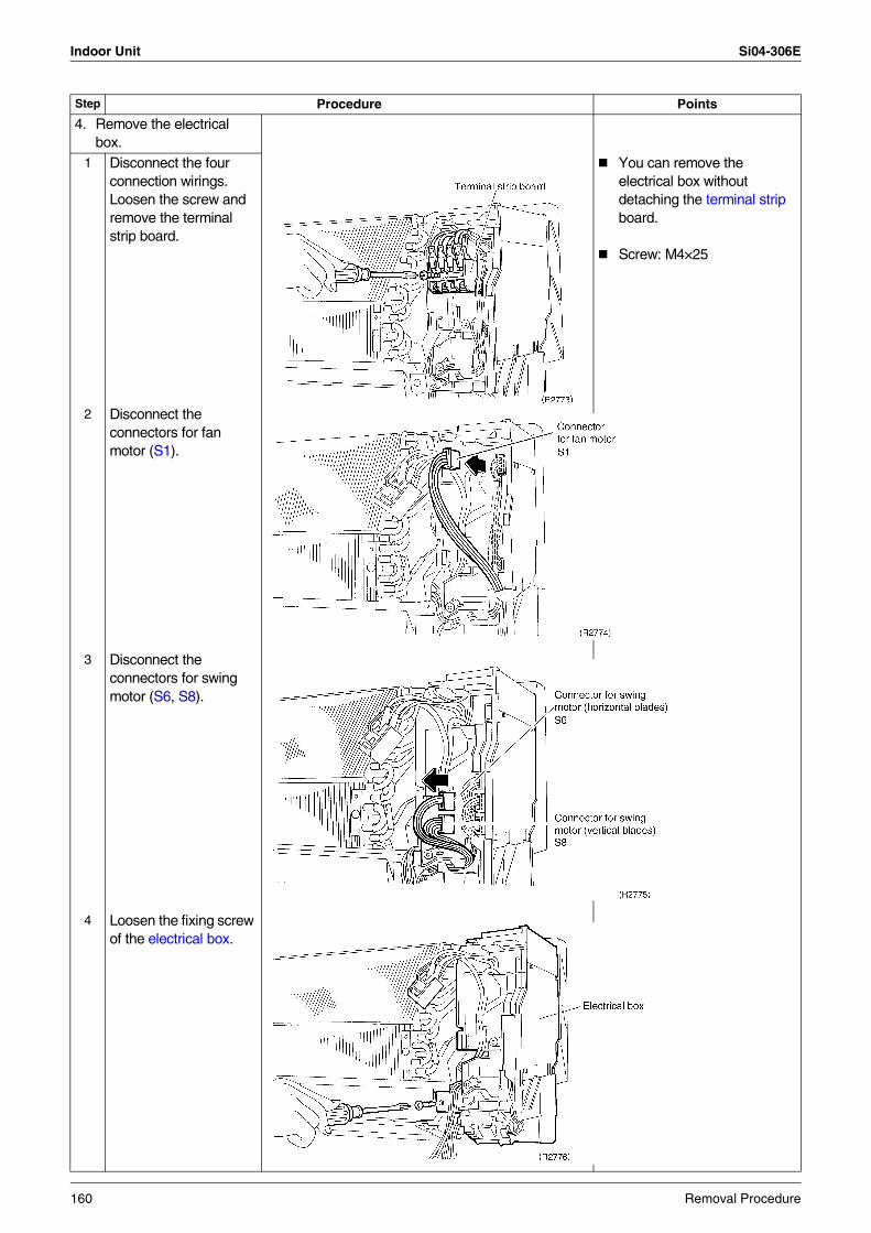
Indoor Unit Si04-306E
4. Remove the electrical box.
1 Disconnect the four connection wirings. Loosen the screw and remove the terminal strip board.
You can remove the electrical box without detaching the terminal strip board.
Screw: M4×25
2 Disconnect the connectors for fan motor (S1).
3 Disconnect the connectors for swing motor (S6, S8).
4 Loosen the fixing screw of the electrical box.
Step Procedure Points
160 Removal Procedure
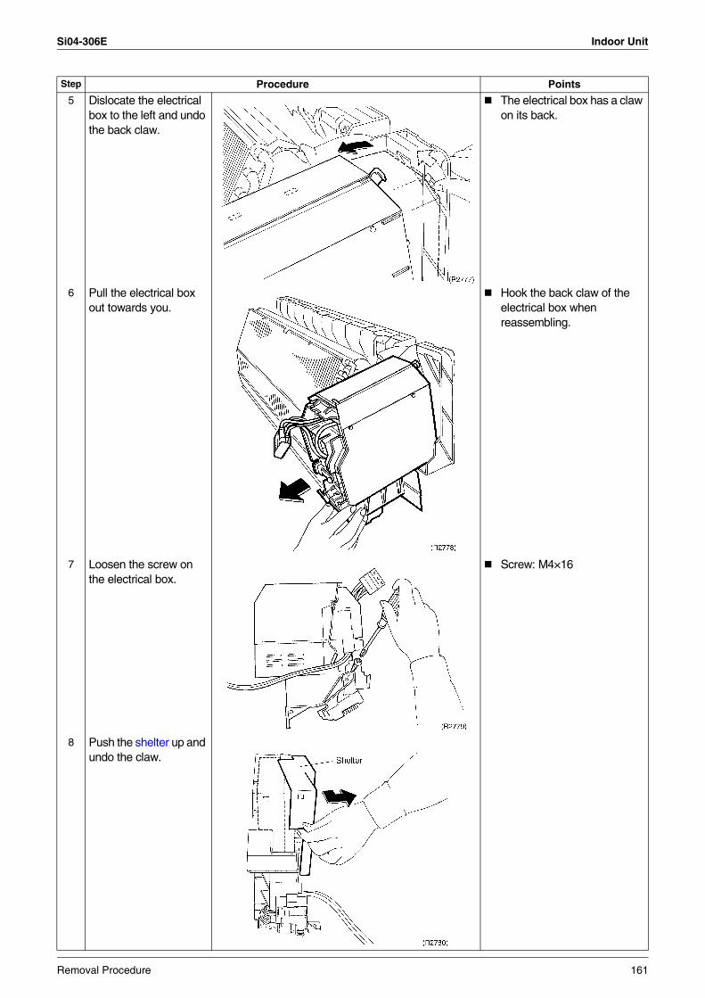
Si04-306E Indoor Unit
5 Dislocate the electrical box to the left and undo the back claw.
The electrical box has a claw on its back.
6 Pull the electrical box out towards you.
Hook the back claw of the electrical box when reassembling.
7 Loosen the screw on the electrical box.
Screw: M4×16
8 Push the shelter up and undo the claw.
Step Procedure Points
Removal Procedure 161
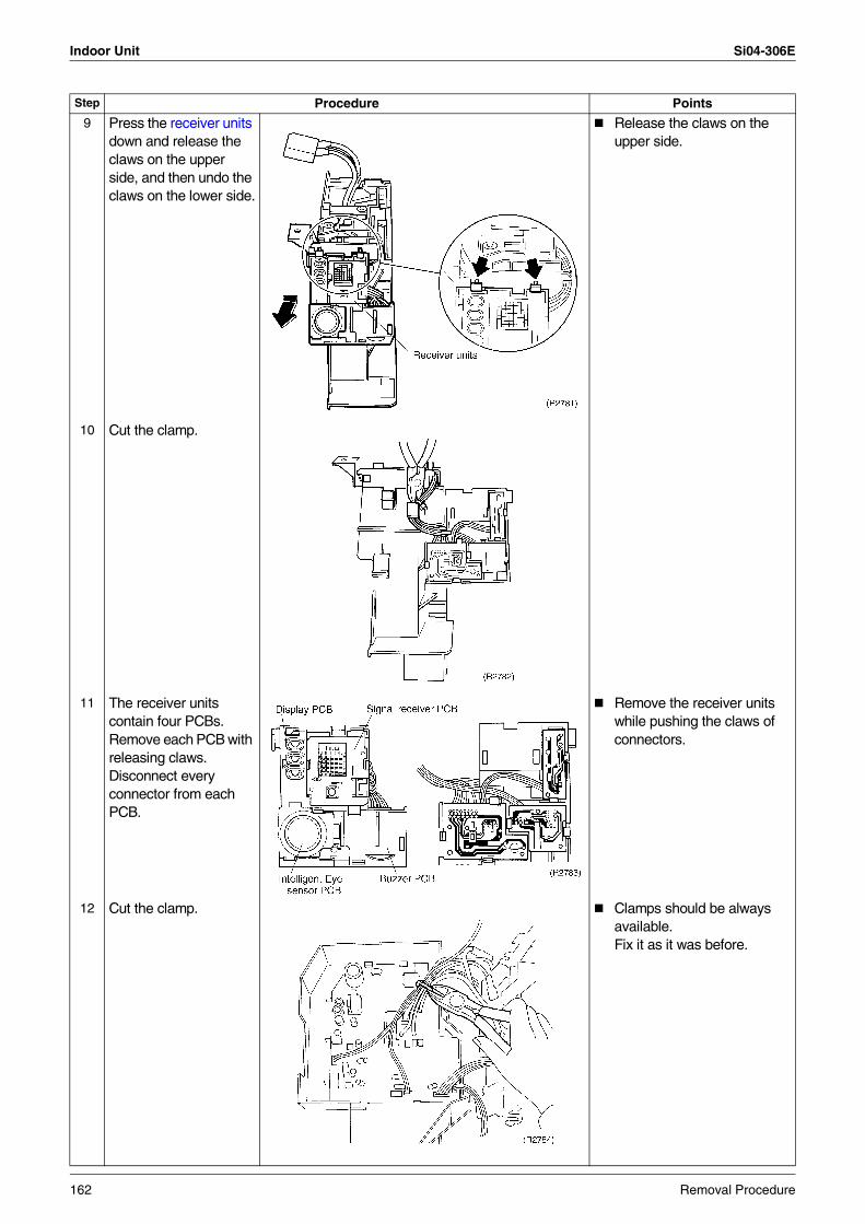
Indoor Unit Si04-306E
9 Press the receiver units down and release the claws on the upper side, and then undo the claws on the lower side.
Release the claws on the upper side.
10 Cut the clamp.
11 The receiver units contain four PCBs.Remove each PCB with releasing claws.Disconnect every connector from each PCB.
Remove the receiver units while pushing the claws of connectors.
12 Cut the clamp. Clamps should be always available. Fix it as it was before.
Step Procedure Points
162 Removal Procedure
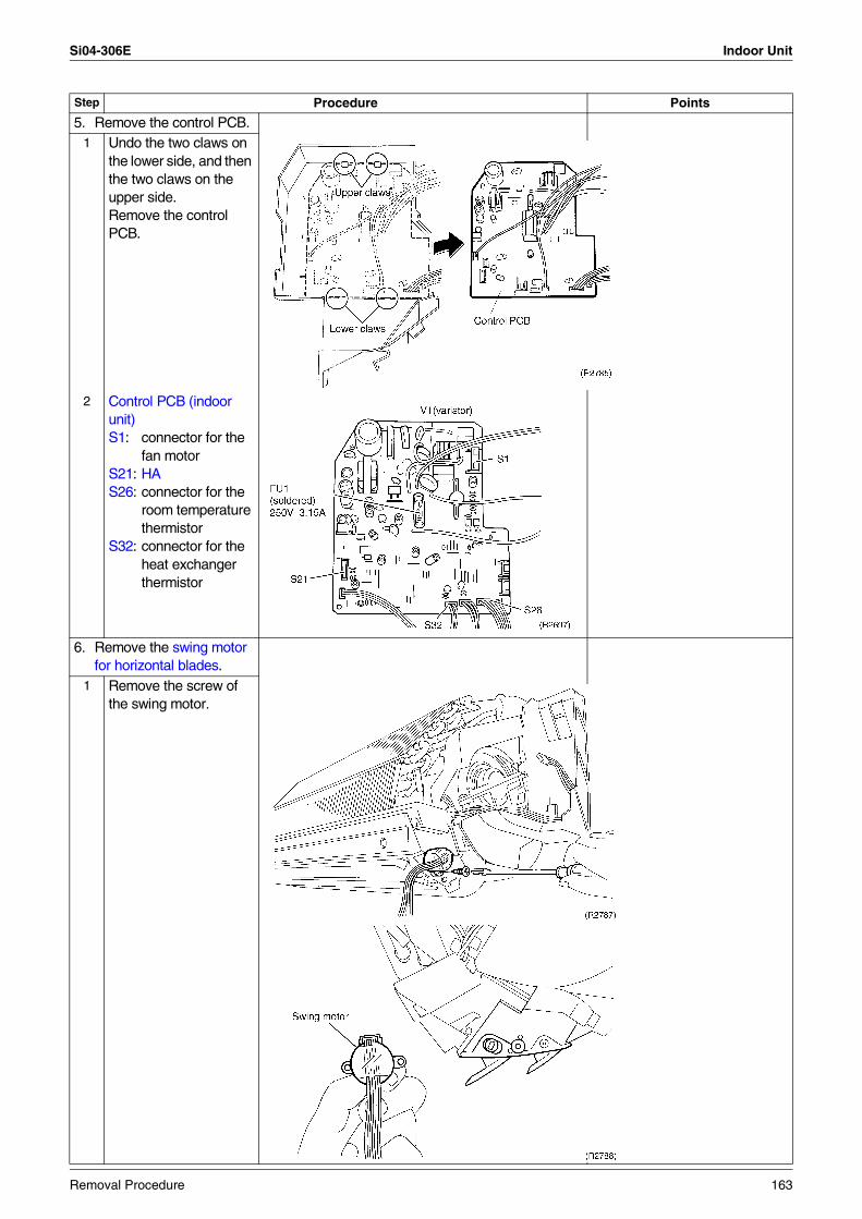
Si04-306E Indoor Unit
5. Remove the control PCB.1 Undo the two claws on
the lower side, and then the two claws on the upper side. Remove the control PCB.
2 Control PCB (indoor unit)S1: connector for the
fan motorS21: HAS26: connector for the
room temperature thermistor
S32: connector for the heat exchanger thermistor
6. Remove the swing motor for horizontal blades.
1 Remove the screw of the swing motor.
Step Procedure Points
Removal Procedure 163
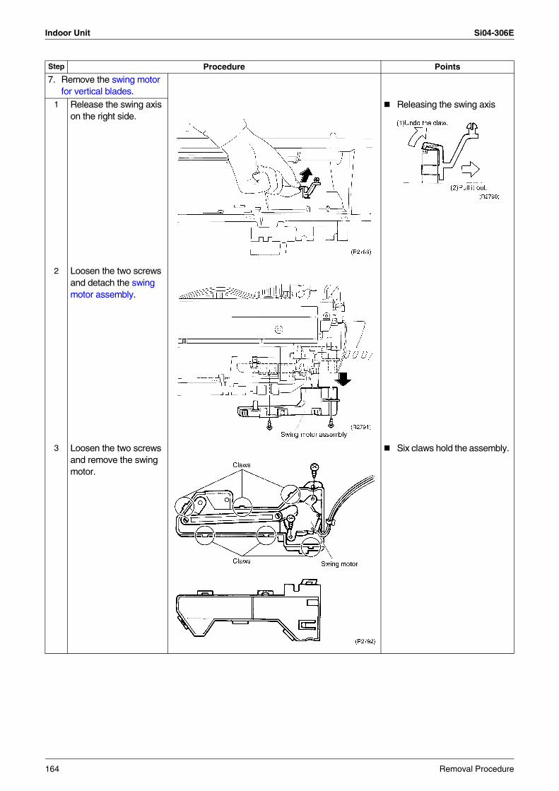
Indoor Unit Si04-306E
7. Remove the swing motor for vertical blades.
1 Release the swing axis on the right side.
Releasing the swing axis
2 Loosen the two screws and detach the swing motor assembly.
3 Loosen the two screws and remove the swing motor.
Six claws hold the assembly.
Step Procedure Points
164 Removal Procedure
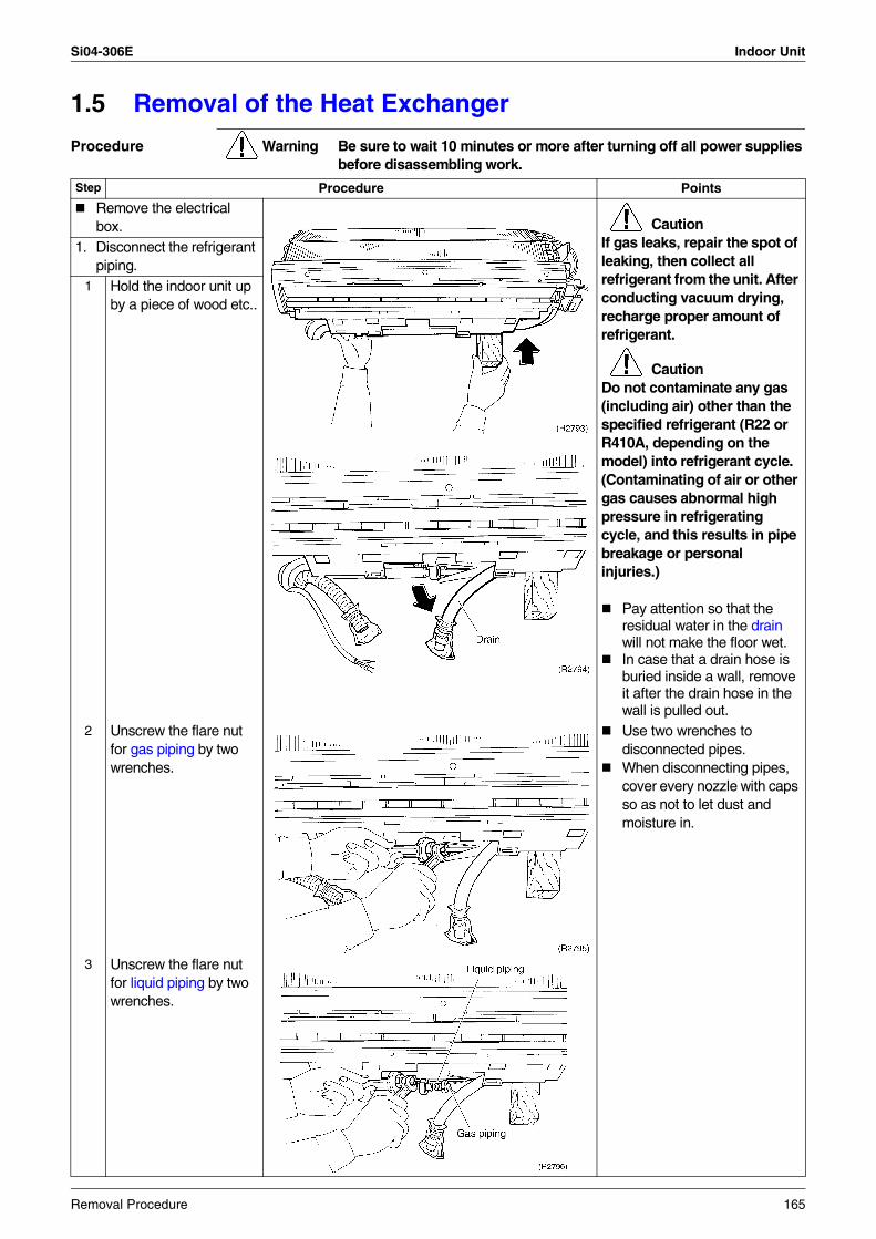
Si04-306E Indoor Unit
1.5 Removal of the Heat Exchanger
Procedure Warning Be sure to wait 10 minutes or more after turning off all power supplies before disassembling work.
Step Procedure Points
Remove the electrical box. Caution
If gas leaks, repair the spot of leaking, then collect all refrigerant from the unit. After conducting vacuum drying, recharge proper amount of refrigerant.
CautionDo not contaminate any gas (including air) other than the specified refrigerant (R22 or R410A, depending on the model) into refrigerant cycle.(Contaminating of air or other gas causes abnormal high pressure in refrigerating cycle, and this results in pipe breakage or personal injuries.)
Pay attention so that the residual water in the drain will not make the floor wet.In case that a drain hose is buried inside a wall, remove it after the drain hose in the wall is pulled out.
1. Disconnect the refrigerant piping.
1 Hold the indoor unit up by a piece of wood etc..
2 Unscrew the flare nut for gas piping by two wrenches.
Use two wrenches to disconnected pipes.When disconnecting pipes, cover every nozzle with caps so as not to let dust and moisture in.
3 Unscrew the flare nut for liquid piping by two wrenches.
Removal Procedure 165
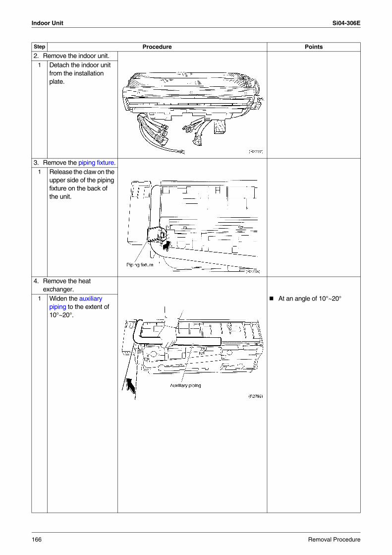
Indoor Unit Si04-306E
2. Remove the indoor unit.1 Detach the indoor unit
from the installation plate.
3. Remove the piping fixture.1 Release the claw on the
upper side of the piping fixture on the back of the unit.
4. Remove the heat exchanger.
1 Widen the auxiliary piping to the extent of 10°~20°.
At an angle of 10°~20°
Step Procedure Points
166 Removal Procedure
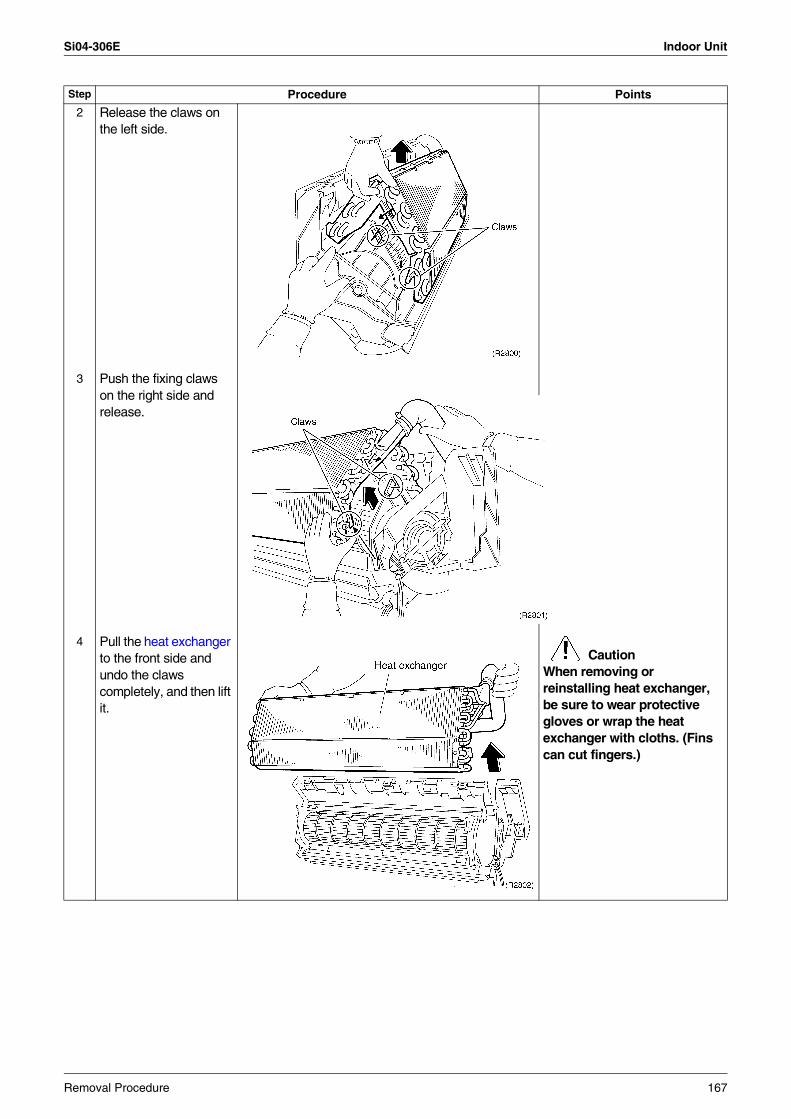
Si04-306E Indoor Unit
2 Release the claws on the left side.
3 Push the fixing claws on the right side and release.
4 Pull the heat exchanger to the front side and undo the claws completely, and then lift it.
CautionWhen removing or reinstalling heat exchanger, be sure to wear protective gloves or wrap the heat exchanger with cloths. (Fins can cut fingers.)
Step Procedure Points
Removal Procedure 167
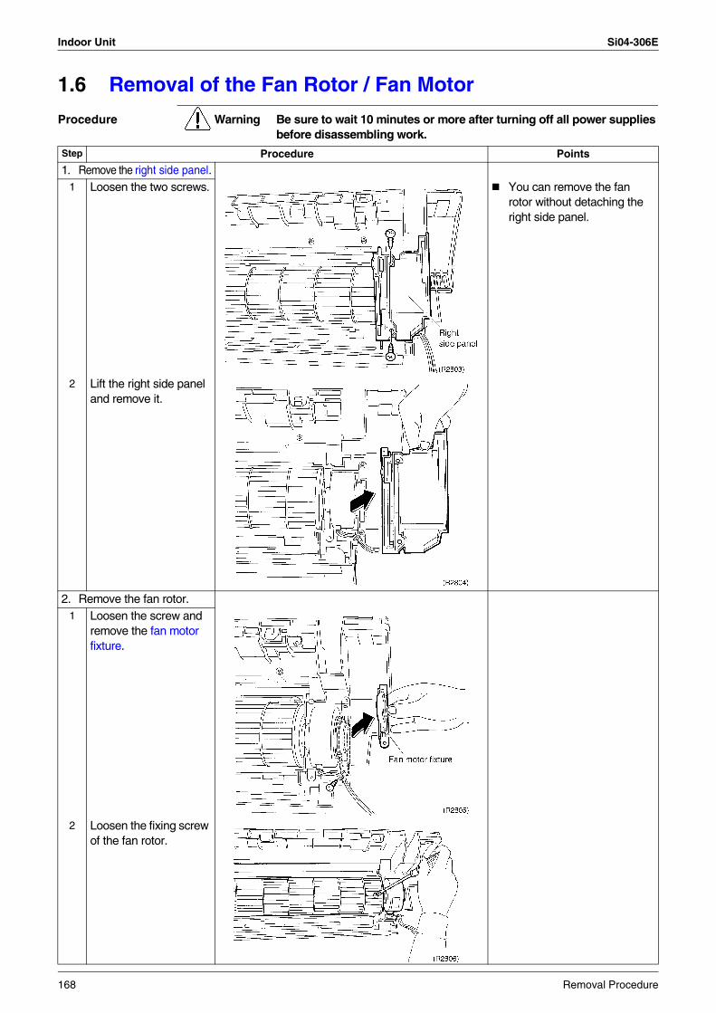
Indoor Unit Si04-306E
1.6 Removal of the Fan Rotor / Fan Motor
Procedure Warning Be sure to wait 10 minutes or more after turning off all power supplies before disassembling work.
Step Procedure Points
1. Remove the right side panel.1 Loosen the two screws. You can remove the fan
rotor without detaching the right side panel.
2 Lift the right side panel and remove it.
2. Remove the fan rotor.1 Loosen the screw and
remove the fan motor fixture.
2 Loosen the fixing screw of the fan rotor.
168 Removal Procedure
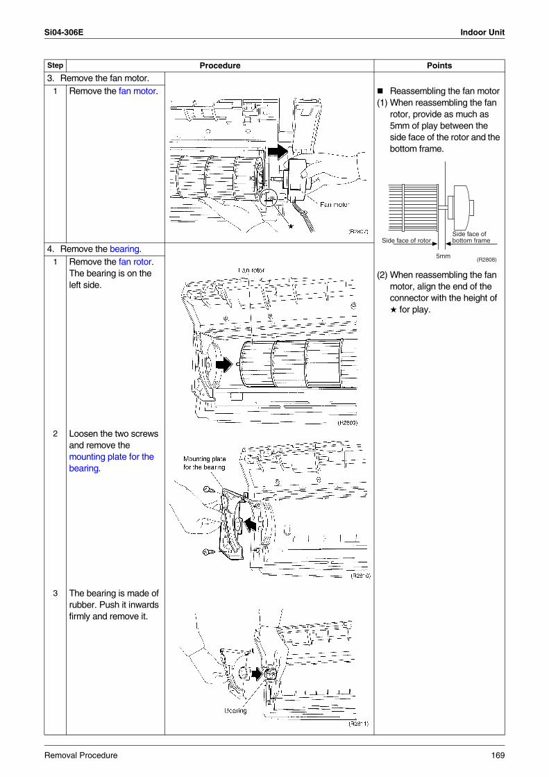
Si04-306E Indoor Unit
3. Remove the fan motor.1 Remove the fan motor. Reassembling the fan motor
(1) When reassembling the fan rotor, provide as much as 5mm of play between the side face of the rotor and the bottom frame.
(2) When reassembling the fan motor, align the end of the connector with the height of for play.
4. Remove the bearing.1 Remove the fan rotor.
The bearing is on the left side.
2 Loosen the two screws and remove the mounting plate for the bearing.
3 The bearing is made of rubber. Push it inwards firmly and remove it.
Step Procedure Points
5mm
Side face ofbottom frameSide face of rotor
(R2808)
Removal Procedure 169
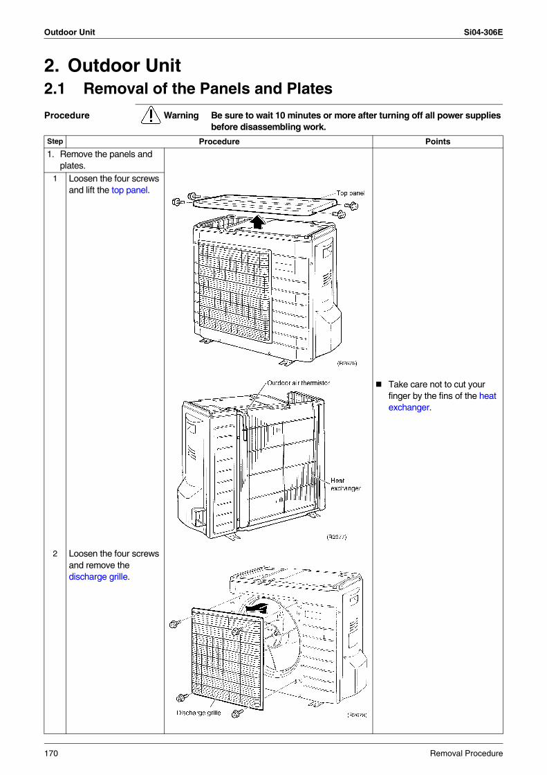
Outdoor Unit Si04-306E
2. Outdoor Unit2.1 Removal of the Panels and Plates
Procedure Warning Be sure to wait 10 minutes or more after turning off all power supplies before disassembling work.
Step Procedure Points
1. Remove the panels and plates.
Take care not to cut your finger by the fins of the heat exchanger.
1 Loosen the four screws and lift the top panel.
2 Loosen the four screws and remove the discharge grille.
170 Removal Procedure
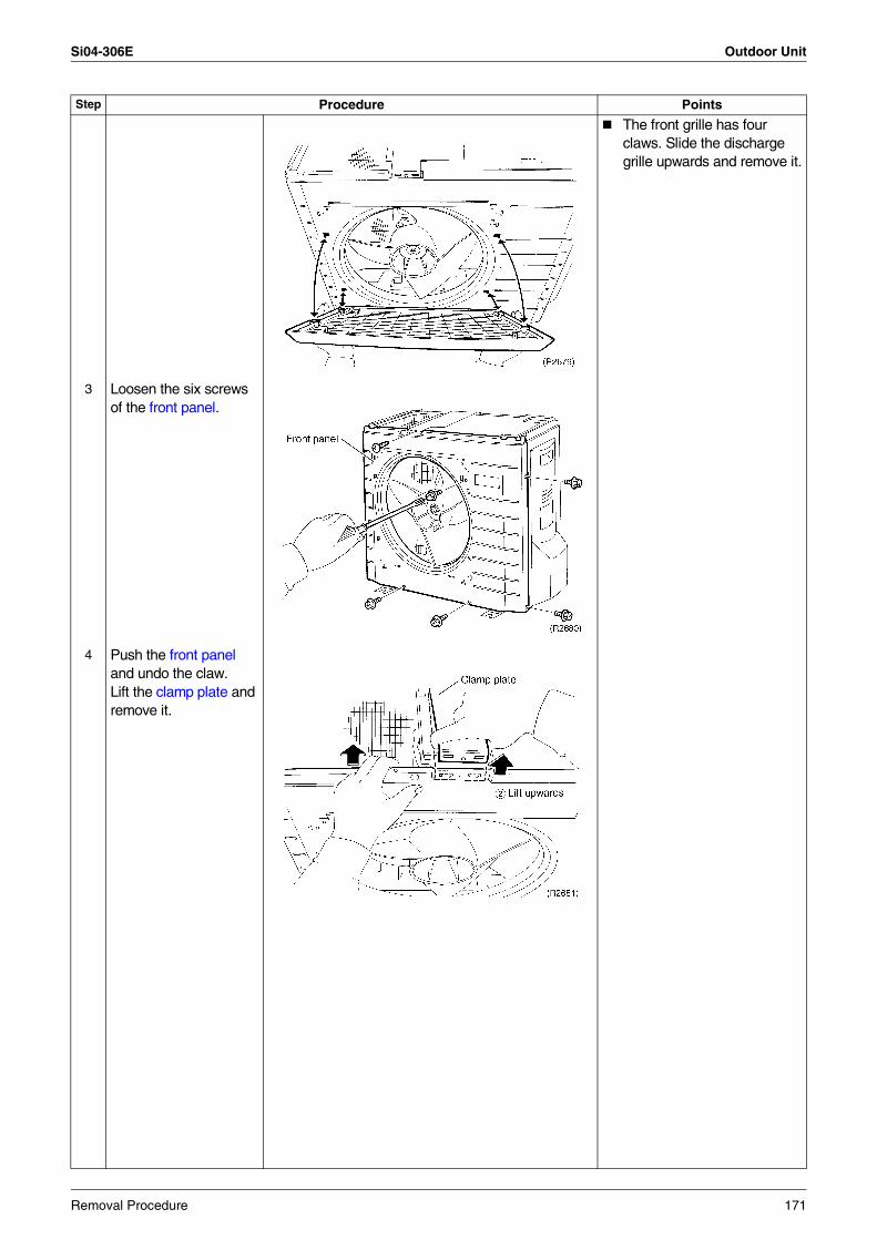
Si04-306E Outdoor Unit
The front grille has four claws. Slide the discharge grille upwards and remove it.
3 Loosen the six screws of the front panel.
4 Push the front panel and undo the claw. Lift the clamp plate and remove it.
Step Procedure Points
Removal Procedure 171
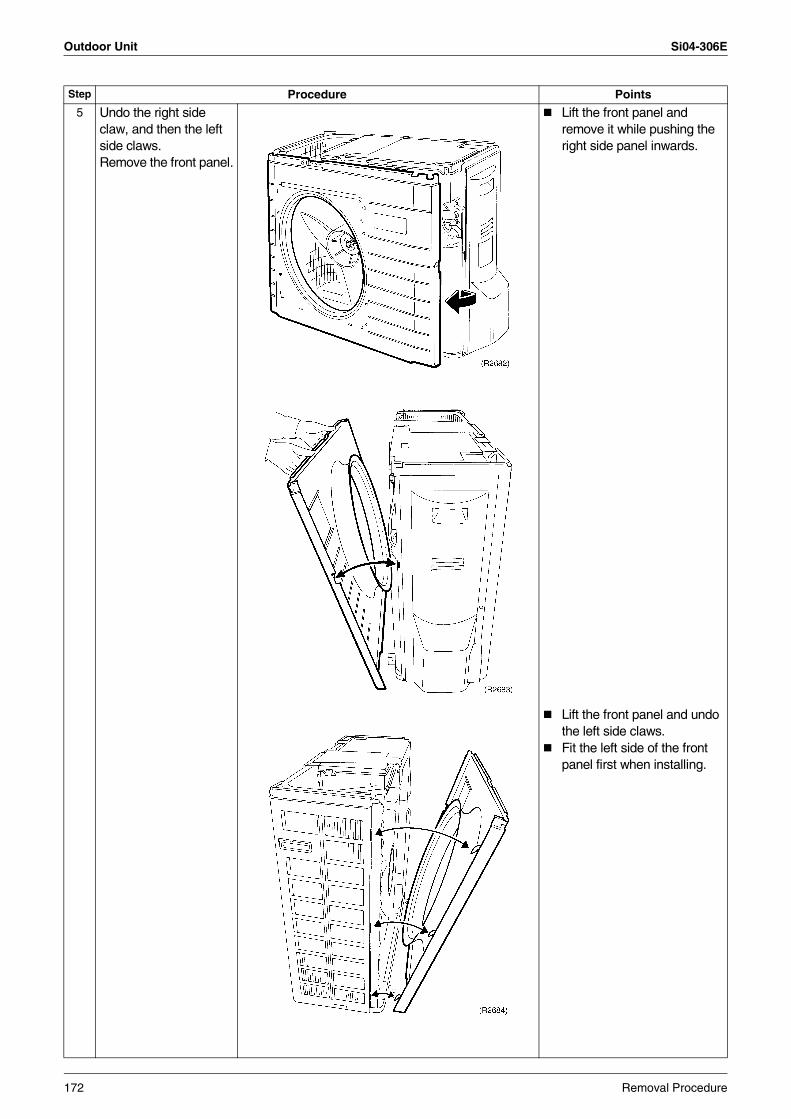
Outdoor Unit Si04-306E
5 Undo the right side claw, and then the left side claws.Remove the front panel.
Lift the front panel and remove it while pushing the right side panel inwards.
Lift the front panel and undo the left side claws.Fit the left side of the front panel first when installing.
Step Procedure Points
172 Removal Procedure
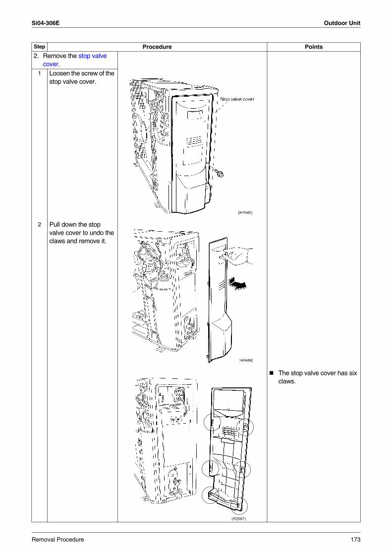
Si04-306E Outdoor Unit
2. Remove the stop valve cover.
1 Loosen the screw of the stop valve cover.
2 Pull down the stop valve cover to undo the claws and remove it.
The stop valve cover has six claws.
Step Procedure Points
(R2687)
Removal Procedure 173
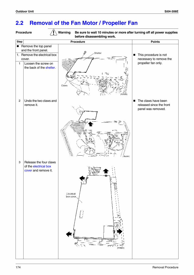
Outdoor Unit Si04-306E
2.2 Removal of the Fan Motor / Propeller Fan
Procedure Warning Be sure to wait 10 minutes or more after turning off all power supplies before disassembling work.
Step Procedure Points
Remove the top panel and the front panel.
1. Remove the electrical box cover.
This procedure is not necessary to remove the propeller fan only.1 Loosen the screw on
the back of the shelter.
2 Undo the two claws and remove it.
The claws have been released since the front panel was removed.
3 Release the four claws of the electrical box cover and remove it.
(R2688)
Shelter
Claws
174 Removal Procedure
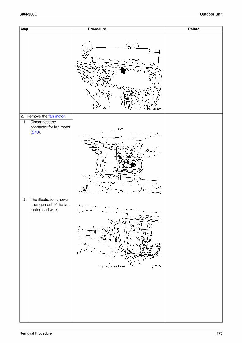
Si04-306E Outdoor Unit
2. Remove the fan motor.1 Disconnect the
connector for fan motor (S70).
2 The illustration shows arrangement of the fan motor lead wire.
Step Procedure Points
Removal Procedure 175
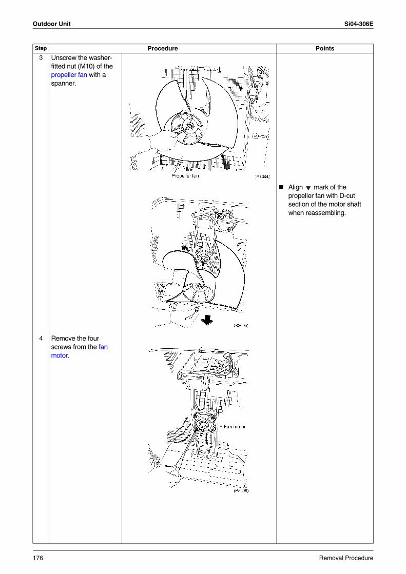
Outdoor Unit Si04-306E
3 Unscrew the washer-fitted nut (M10) of the propeller fan with a spanner.
Align mark of the propeller fan with D-cut section of the motor shaft when reassembling.
4 Remove the four screws from the fan motor.
Step Procedure Points
176 Removal Procedure
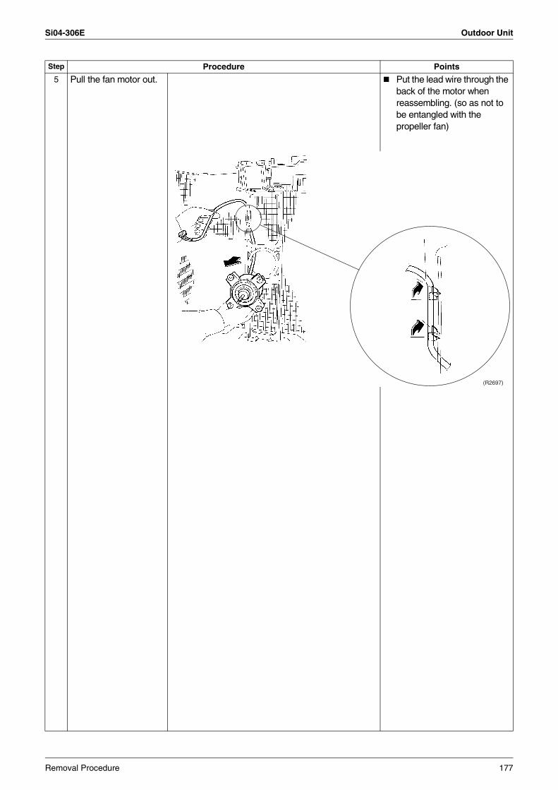
Si04-306E Outdoor Unit
5 Pull the fan motor out. Put the lead wire through the back of the motor when reassembling. (so as not to be entangled with the propeller fan)
Step Procedure Points
(R2697)
Removal Procedure 177
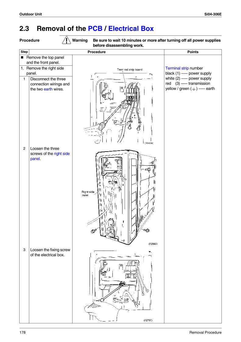
Outdoor Unit Si04-306E
2.3 Removal of the PCB / Electrical Box
Procedure Warning Be sure to wait 10 minutes or more after turning off all power supplies before disassembling work.
Step Procedure Points
Remove the top panel and the front panel.
1. Remove the right side panel.
Terminal strip numberblack (1) ----- power supplywhite (2) ----- power supplyred (3) ----- transmissionyellow / green ( ) ----- earth
1 Disconnect the three connection wirings and the two earth wires.
2 Loosen the three screws of the right side panel.
3 Loosen the fixing screw of the electrical box.
178 Removal Procedure
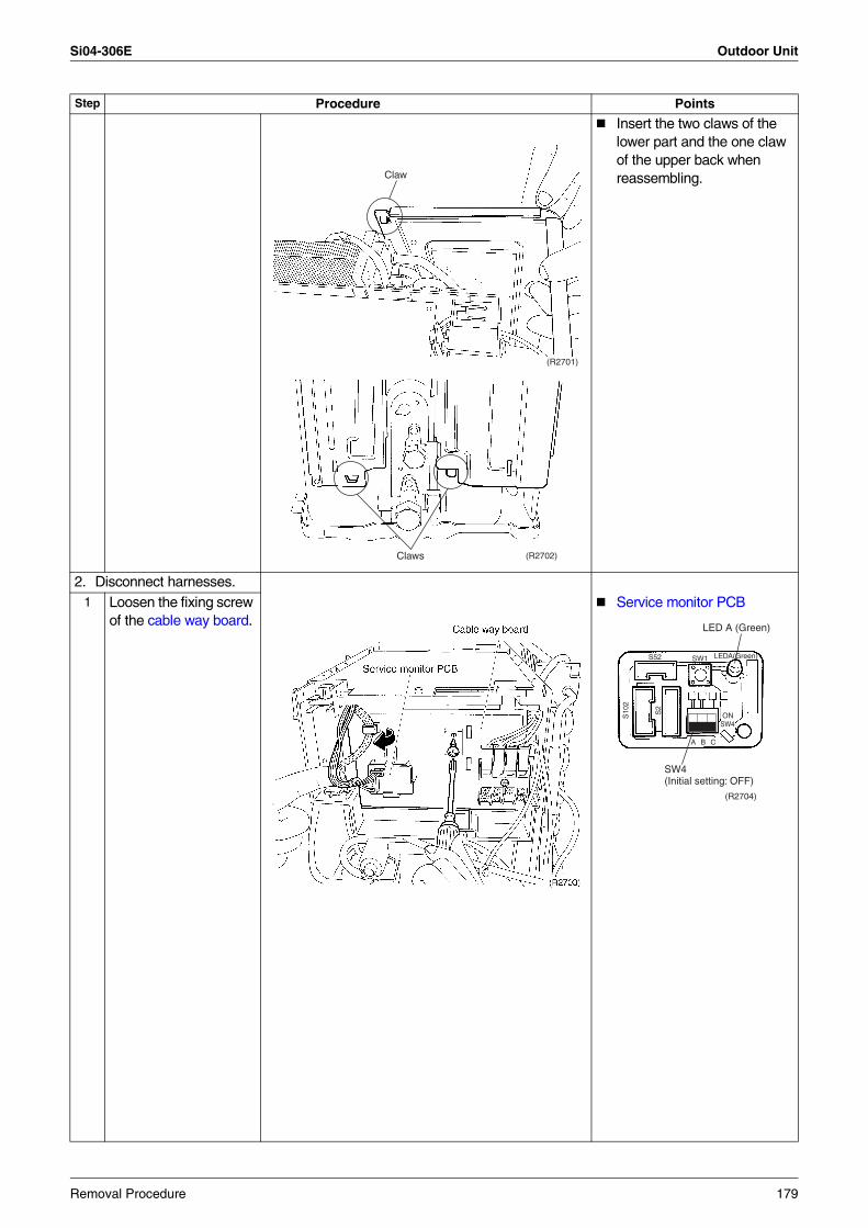
Si04-306E Outdoor Unit
Insert the two claws of the lower part and the one claw of the upper back when reassembling.
2. Disconnect harnesses.1 Loosen the fixing screw
of the cable way board.Service monitor PCB
Step Procedure Points
(R2701)
Claw
(R2702)Claws
S52 SW1
A B C
LEDA(Green)
SW4(Initial setting: OFF)
LED A (Green)
ONSW4
S10
2
S2
(R2704)
Removal Procedure 179
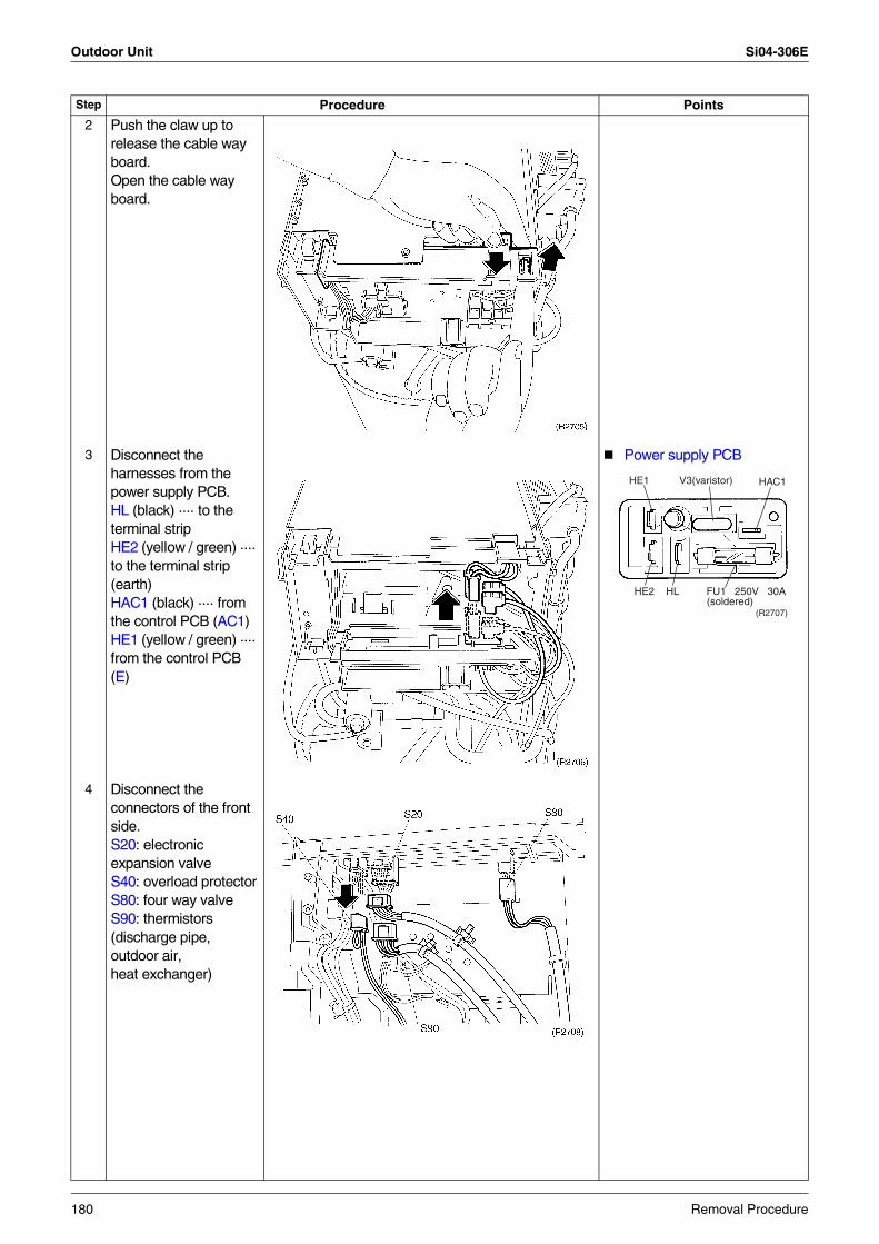
Outdoor Unit Si04-306E
2 Push the claw up to release the cable way board. Open the cable way board.
3 Disconnect the harnesses from the power supply PCB.HL (black) ···· to the terminal stripHE2 (yellow / green) ···· to the terminal strip (earth)HAC1 (black) ···· from the control PCB (AC1)HE1 (yellow / green) ···· from the control PCB (E)
Power supply PCB
4 Disconnect the connectors of the front side.S20: electronic expansion valveS40: overload protectorS80: four way valveS90: thermistors (discharge pipe, outdoor air, heat exchanger)
Step Procedure Points
HE1 V3(varistor)
(soldered)HE2 HL FU1 250V 30A
HAC1
(R2707)
180 Removal Procedure
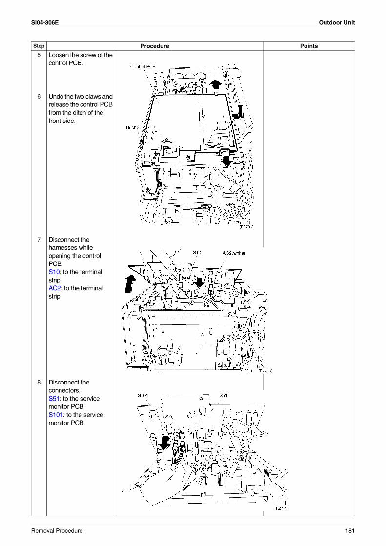
Si04-306E Outdoor Unit
5 Loosen the screw of the control PCB.
6 Undo the two claws and release the control PCB from the ditch of the front side.
7 Disconnect the harnesses while opening the control PCB.S10: to the terminal stripAC2: to the terminal strip
8 Disconnect the connectors.S51: to the service monitor PCBS101: to the service monitor PCB
Step Procedure Points
Removal Procedure 181
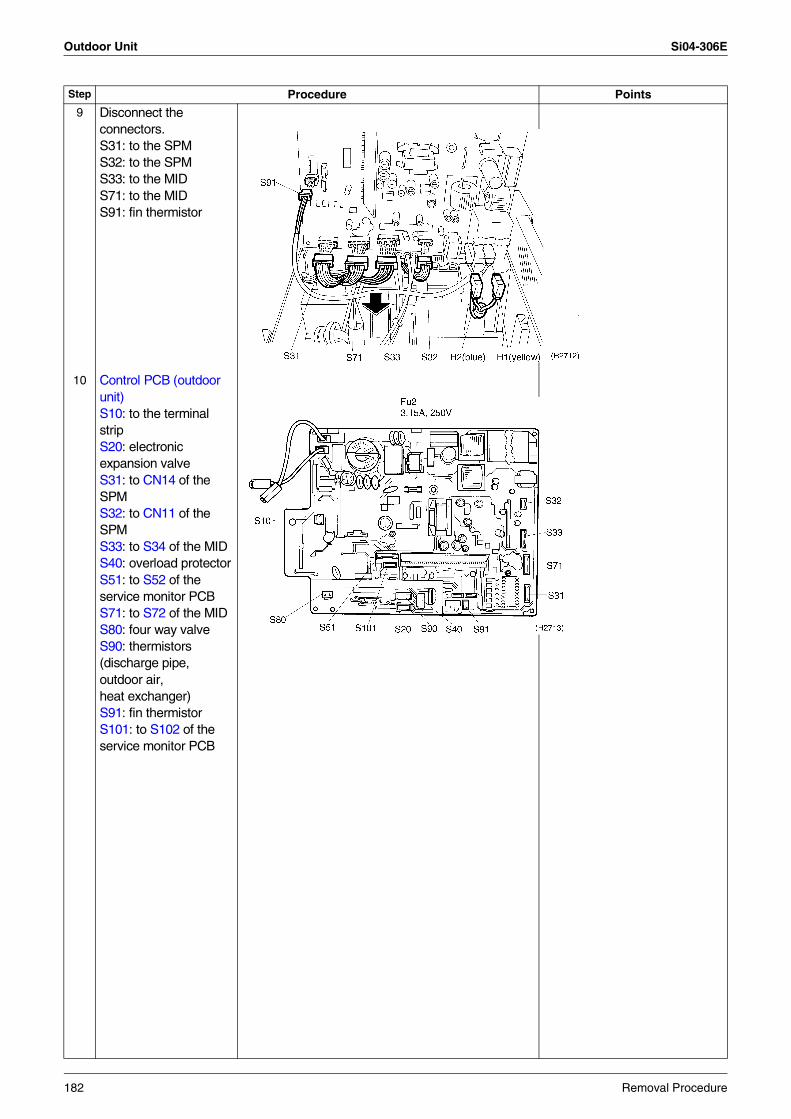
Outdoor Unit Si04-306E
9 Disconnect the connectors.S31: to the SPMS32: to the SPMS33: to the MIDS71: to the MIDS91: fin thermistor
10 Control PCB (outdoor unit)S10: to the terminal stripS20: electronic expansion valveS31: to CN14 of the SPMS32: to CN11 of the SPMS33: to S34 of the MIDS40: overload protectorS51: to S52 of the service monitor PCBS71: to S72 of the MIDS80: four way valveS90: thermistors (discharge pipe, outdoor air, heat exchanger)S91: fin thermistorS101: to S102 of the service monitor PCB
Step Procedure Points
182 Removal Procedure
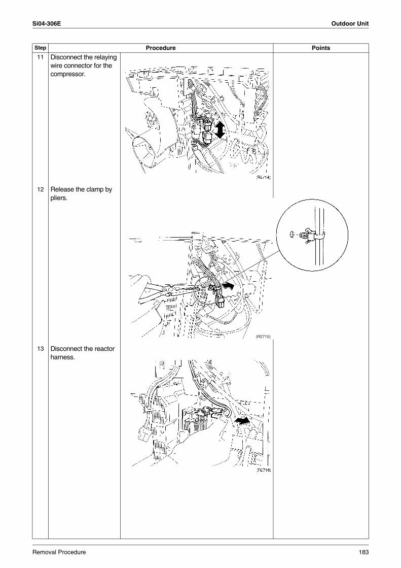
Si04-306E Outdoor Unit
11 Disconnect the relaying wire connector for the compressor.
12 Release the clamp by pliers.
13 Disconnect the reactor harness.
Step Procedure Points
(R2715)
Removal Procedure 183
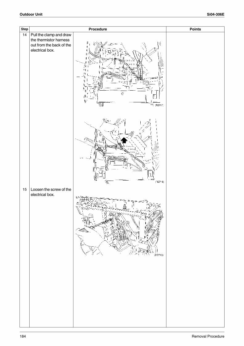
Outdoor Unit Si04-306E
14 Pull the clamp and draw the thermistor harness out from the back of the electrical box.
15 Loosen the screw of the electrical box.
Step Procedure Points
184 Removal Procedure
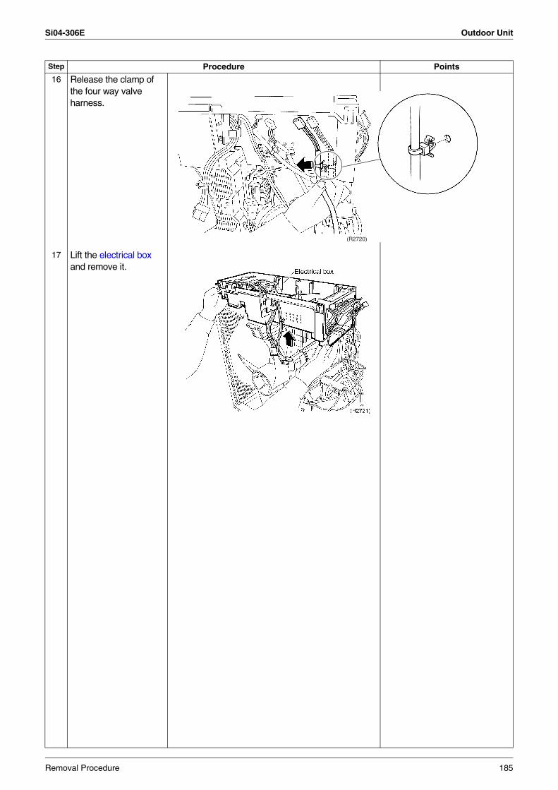
Si04-306E Outdoor Unit
16 Release the clamp of the four way valve harness.
17 Lift the electrical box and remove it.
Step Procedure Points
(R2720)
Removal Procedure 185
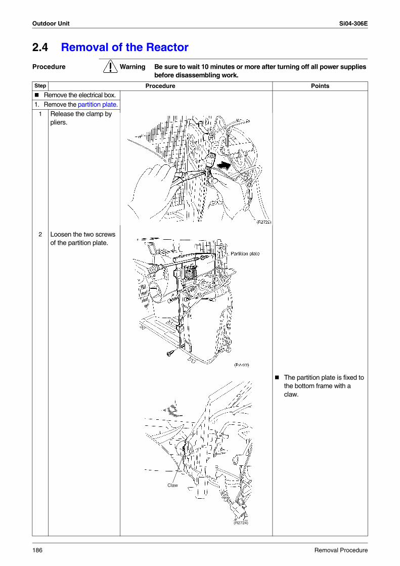
Outdoor Unit Si04-306E
2.4 Removal of the Reactor
Procedure Warning Be sure to wait 10 minutes or more after turning off all power supplies before disassembling work.
Step Procedure Points
Remove the electrical box.1. Remove the partition plate.
1 Release the clamp by pliers.
2 Loosen the two screws of the partition plate.
The partition plate is fixed to the bottom frame with a claw.
(R2724)
Claw
186 Removal Procedure
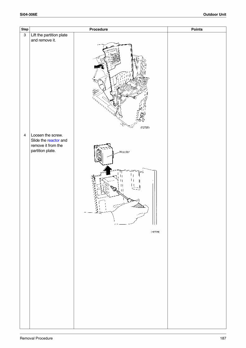
Si04-306E Outdoor Unit
3 Lift the partition plate and remove it.
4 Loosen the screw.Slide the reactor and remove it from the partition plate.
Step Procedure Points
Removal Procedure 187
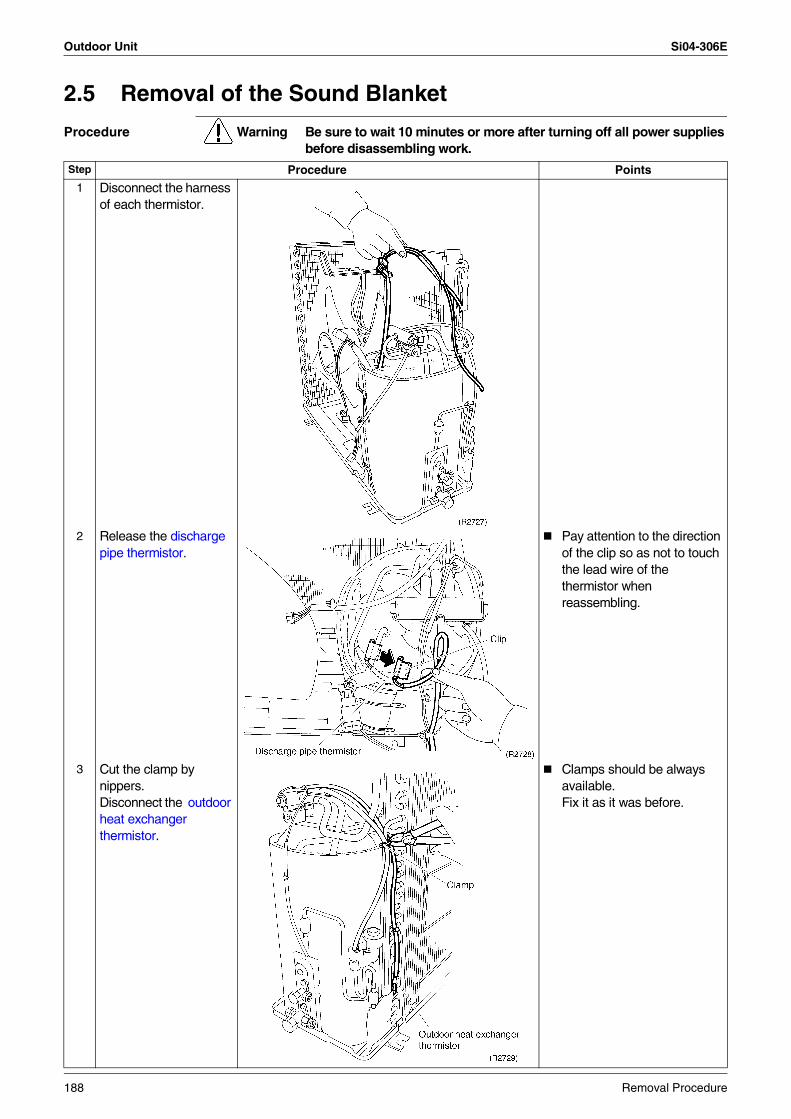
Outdoor Unit Si04-306E
2.5 Removal of the Sound Blanket
Procedure Warning Be sure to wait 10 minutes or more after turning off all power supplies before disassembling work.
Step Procedure Points
1 Disconnect the harness of each thermistor.
2 Release the discharge pipe thermistor.
Pay attention to the direction of the clip so as not to touch the lead wire of the thermistor when reassembling.
3 Cut the clamp by nippers.Disconnect the outdoor heat exchanger thermistor.
Clamps should be always available. Fix it as it was before.
188 Removal Procedure
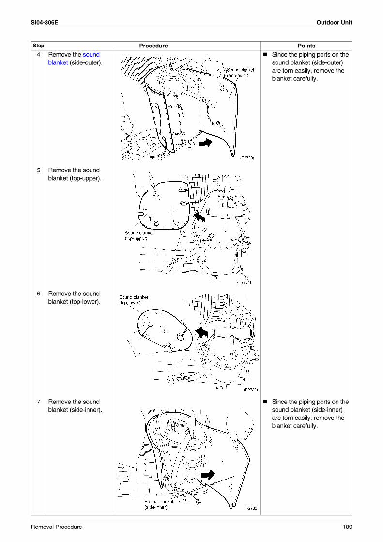
Si04-306E Outdoor Unit
4 Remove the sound blanket (side-outer).
Since the piping ports on the sound blanket (side-outer) are torn easily, remove the blanket carefully.
5 Remove the sound blanket (top-upper).
6 Remove the sound blanket (top-lower).
7 Remove the sound blanket (side-inner).
Since the piping ports on the sound blanket (side-inner) are torn easily, remove the blanket carefully.
Step Procedure Points
Removal Procedure 189
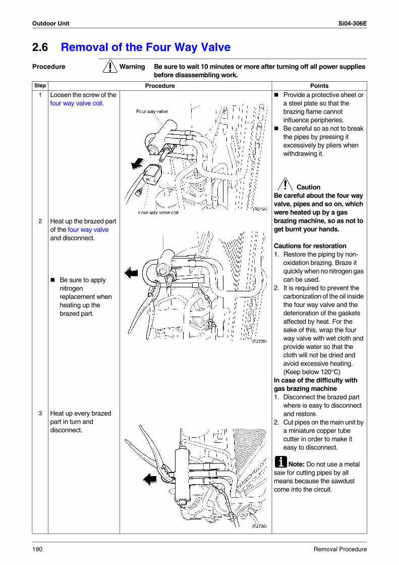
Outdoor Unit Si04-306E
2.6 Removal of the Four Way Valve
Procedure Warning Be sure to wait 10 minutes or more after turning off all power supplies before disassembling work.
Step Procedure Points
1 Loosen the screw of the four way valve coil.
Provide a protective sheet or a steel plate so that the brazing flame cannot influence peripheries.Be careful so as not to break the pipes by pressing it excessively by pliers when withdrawing it.
CautionBe careful about the four way valve, pipes and so on, which were heated up by a gas brazing machine, so as not to get burnt your hands.
Cautions for restoration1. Restore the piping by non-
oxidation brazing. Braze it quickly when no nitrogen gas can be used.
2. It is required to prevent the carbonization of the oil inside the four way valve and the deterioration of the gaskets affected by heat. For the sake of this, wrap the four way valve with wet cloth and provide water so that the cloth will not be dried and avoid excessive heating. (Keep below 120°C)
In case of the difficulty with gas brazing machine 1. Disconnect the brazed part
where is easy to disconnect and restore.
2. Cut pipes on the main unit by a miniature copper tube cutter in order to make it easy to disconnect.
Note: Do not use a metal saw for cutting pipes by all means because the sawdust come into the circuit.
2 Heat up the brazed part of the four way valve and disconnect.
Be sure to apply nitrogen replacement when heating up the brazed part.
3 Heat up every brazed part in turn and disconnect.
190 Removal Procedure
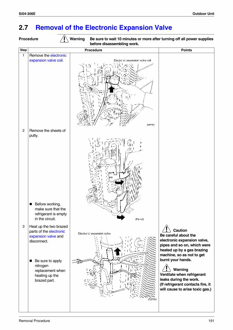
Si04-306E Outdoor Unit
2.7 Removal of the Electronic Expansion Valve
Procedure Warning Be sure to wait 10 minutes or more after turning off all power supplies before disassembling work.
Step Procedure Points
1 Remove the electronic expansion valve coil.
2 Remove the sheets of putty.
Before working, make sure that the refrigerant is empty in the circuit.
3 Heat up the two brazed parts of the electronic expansion valve and disconnect.
Be sure to apply nitrogen replacement when heating up the brazed part.
CautionBe careful about the electronic expansion valve, pipes and so on, which were heated up by a gas brazing machine, so as not to get burnt your hands.
WarningVentilate when refrigerant leaks during the work.(If refrigerant contacts fire, it will cause to arise toxic gas.)
Removal Procedure 191
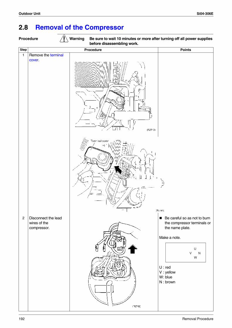
Outdoor Unit Si04-306E
2.8 Removal of the Compressor
Procedure Warning Be sure to wait 10 minutes or more after turning off all power supplies before disassembling work.
Step Procedure Points
1 Remove the terminal cover.
2 Disconnect the lead wires of the compressor.
Be careful so as not to burn the compressor terminals or the name plate.
Make a note.
U : redV : yellowW: blueN : brown
NW
UV
192 Removal Procedure
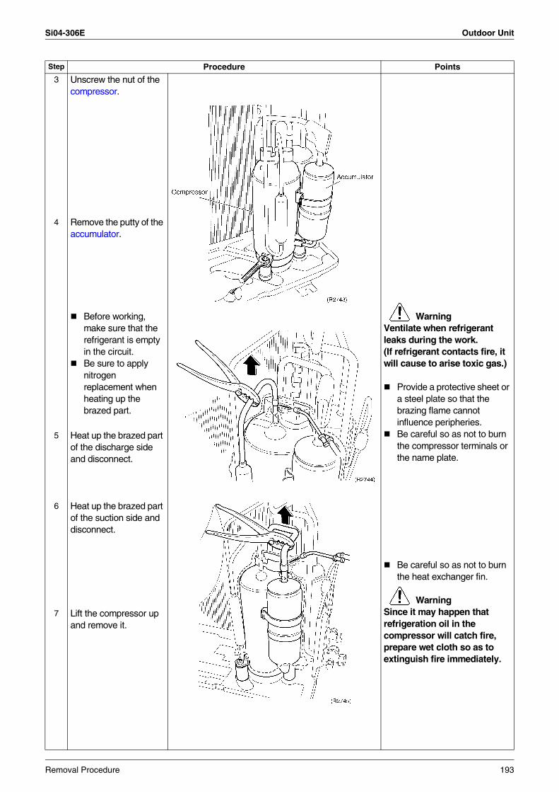
Si04-306E Outdoor Unit
3 Unscrew the nut of the compressor.
4 Remove the putty of the accumulator.
Before working, make sure that the refrigerant is empty in the circuit.Be sure to apply nitrogen replacement when heating up the brazed part.
WarningVentilate when refrigerant leaks during the work.(If refrigerant contacts fire, it will cause to arise toxic gas.)
Provide a protective sheet or a steel plate so that the brazing flame cannot influence peripheries.Be careful so as not to burn the compressor terminals or the name plate.
5 Heat up the brazed part of the discharge side and disconnect.
6 Heat up the brazed part of the suction side and disconnect.
Be careful so as not to burn the heat exchanger fin.
WarningSince it may happen that refrigeration oil in the compressor will catch fire, prepare wet cloth so as to extinguish fire immediately.
7 Lift the compressor up and remove it.
Step Procedure Points
Removal Procedure 193
Outdoor Unit Si04-306E
194 Removal Procedure
Si04-306E
Others 195
Part 8Others
1. Others .................................................................................................1961.1 Test Run from the Remote Controller ..................................................1961.2 Jumper Settings ...................................................................................1971.3 Application of Silicon Grease to a Power Transistor and
a Diode Bridge......................................................................................198
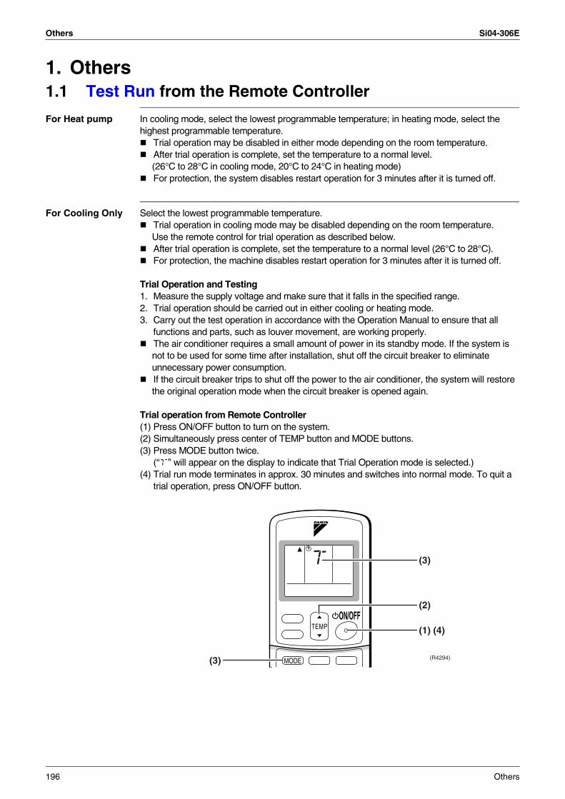
Others Si04-306E
1. Others1.1 Test Run from the Remote Controller
For Heat pump In cooling mode, select the lowest programmable temperature; in heating mode, select the highest programmable temperature.
Trial operation may be disabled in either mode depending on the room temperature.After trial operation is complete, set the temperature to a normal level.(26°C to 28°C in cooling mode, 20°C to 24°C in heating mode)For protection, the system disables restart operation for 3 minutes after it is turned off.
For Cooling Only Select the lowest programmable temperature.Trial operation in cooling mode may be disabled depending on the room temperature. Use the remote control for trial operation as described below.After trial operation is complete, set the temperature to a normal level (26°C to 28°C).For protection, the machine disables restart operation for 3 minutes after it is turned off.
Trial Operation and Testing1. Measure the supply voltage and make sure that it falls in the specified range.2. Trial operation should be carried out in either cooling or heating mode.3. Carry out the test operation in accordance with the Operation Manual to ensure that all
functions and parts, such as louver movement, are working properly.The air conditioner requires a small amount of power in its standby mode. If the system is not to be used for some time after installation, shut off the circuit breaker to eliminate unnecessary power consumption.If the circuit breaker trips to shut off the power to the air conditioner, the system will restore the original operation mode when the circuit breaker is opened again.
Trial operation from Remote Controller(1) Press ON/OFF button to turn on the system.(2) Simultaneously press center of TEMP button and MODE buttons.(3) Press MODE button twice.
(“T” will appear on the display to indicate that Trial Operation mode is selected.)(4) Trial run mode terminates in approx. 30 minutes and switches into normal mode. To quit a
trial operation, press ON/OFF button.
TEMPON/OFF
MODE
(2)
(1) (4)
(3)
(3) (R4294)
196 Others
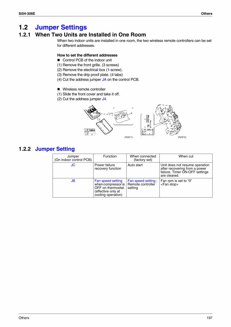
Si04-306E Others
1.2 Jumper Settings1.2.1 When Two Units are Installed in One Room
When two indoor units are installed in one room, the two wireless remote controllers can be set for different addresses.
How to set the different addressesControl PCB of the indoor unit
(1) Remove the front grille. (3 screws)(2) Remove the electrical box (1-screw).(3) Remove the drip proof plate. (4 tabs)(4) Cut the address jumper JA on the control PCB.
Wireless remote controller(1) Slide the front cover and take it off.(2) Cut the address jumper J4.
1.2.2 Jumper Setting
(R2871) (R2872)
Jumper (On indoor control PCB)
Function When connected (factory set)
When cut
JC Power failure recovery function
Auto start Unit does not resume operation after recovering from a power failure. Timer ON-OFF settings are cleared.
JB Fan speed setting when compressor is OFF on thermostat.(effective only at cooling operation)
Fan speed setting ; Remote controller setting
Fan rpm is set to “0” <Fan stop>
Others 197
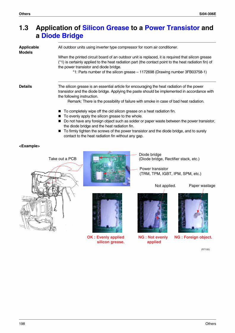
Others Si04-306E
1.3 Application of Silicon Grease to a Power Transistor and a Diode Bridge
Applicable Models
All outdoor units using inverter type compressor for room air conditioner.
When the printed circuit board of an outdoor unit is replaced, it is required that silicon grease (*1) is certainly applied to the heat radiation part (the contact point to the heat radiation fin) of the power transistor and diode bridge. *1: Parts number of the silicon grease – 1172698 (Drawing number 3FB03758-1)
Details The silicon grease is an essential article for encouraging the heat radiation of the power transistor and the diode bridge. Applying the paste should be implemented in accordance with the following instruction. Remark: There is the possibility of failure with smoke in case of bad heat radiation.
To completely wipe off the old silicon grease on a heat radiation fin.To evenly apply the silicon grease to the whole.Do not have any foreign object such as solder or paper waste between the power transistor, the diode bridge and the heat radiation fin.To firmly tighten the screws of the power transistor and the diode bridge, and to surely contact to the heat radiation fin without any gap.
<Example>
Take out a PCBDiode bridge(Diode bridge, Rectifier stack, etc.)
Power transistor(TRM, TPM, IGBT, IPM, SPM, etc.)
Not applied. Paper wastage
OK : Evenly applied silicon grease.
NG : Not evenly applied
NG : Foreign object.
(R7100)
198 Others
Si04-306E
Appendix 199
Part 9Appendix
1. Piping Diagrams..................................................................................2001.1 Indoor Units ..........................................................................................2001.2 Outdoor Units .......................................................................................201
2. Wiring Diagrams..................................................................................2072.1 Indoor Units ..........................................................................................2072.2 Outdoor Units .......................................................................................210
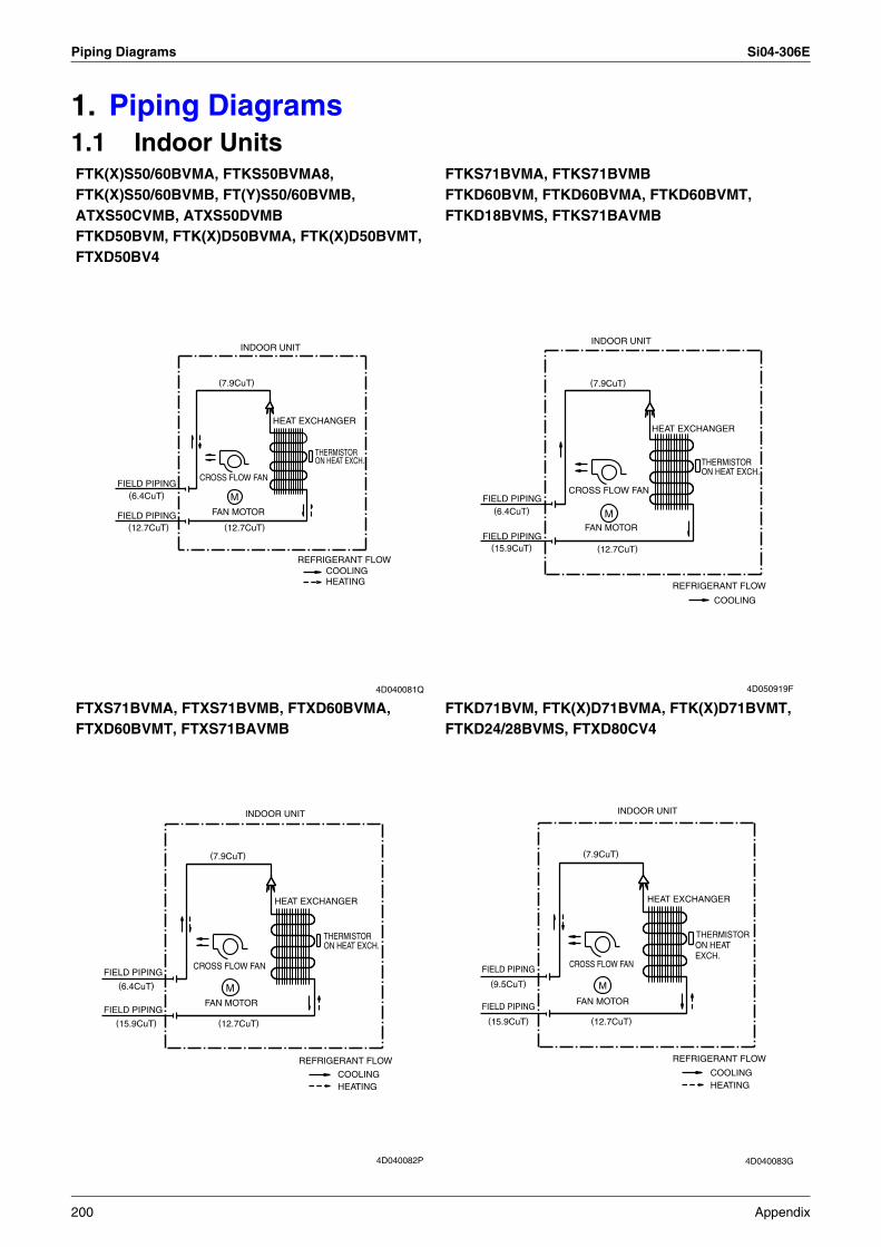
Piping Diagrams Si04-306E
1. Piping Diagrams1.1 Indoor UnitsFTK(X)S50/60BVMA, FTKS50BVMA8, FTK(X)S50/60BVMB, FT(Y)S50/60BVMB, ATXS50CVMB, ATXS50DVMBFTKD50BVM, FTK(X)D50BVMA, FTK(X)D50BVMT, FTXD50BV4
FTKS71BVMA, FTKS71BVMBFTKD60BVM, FTKD60BVMA, FTKD60BVMT, FTKD18BVMS, FTKS71BAVMB
FTXS71BVMA, FTXS71BVMB, FTXD60BVMA, FTXD60BVMT, FTXS71BAVMB
FTKD71BVM, FTK(X)D71BVMA, FTK(X)D71BVMT, FTKD24/28BVMS, FTXD80CV4
FIELD PIPING
FIELD PIPING(12.7CuT)
(6.4CuT)
CROSS FLOW FAN
FAN MOTOR
(7.9CuT)
INDOOR UNIT
(12.7CuT)
M
HEAT EXCHANGER
REFRIGERANT FLOW
ON HEAT EXCH.THERMISTOR
HEATINGCOOLING
4D040081Q
(15.9CuT)
FIELD PIPING
FIELD PIPING
(6.4CuT)
CROSS FLOW FAN
FAN MOTOR
(7.9CuT)
INDOOR UNIT
(12.7CuT)
M
HEAT EXCHANGER
REFRIGERANT FLOW
ON HEAT EXCH.THERMISTOR
COOLING
4D050919F
(15.9CuT)
FIELD PIPING
FIELD PIPING
(6.4CuT)
CROSS FLOW FAN
FAN MOTOR
(7.9CuT)
INDOOR UNIT
(12.7CuT)
M
HEAT EXCHANGER
REFRIGERANT FLOW
ON HEAT EXCH. THERMISTOR
COOLINGHEATING
4D040082P
(15.9CuT)
FIELD PIPING
FIELD PIPING
(9.5CuT)
CROSS FLOW FAN
FAN MOTOR
(7.9CuT)
INDOOR UNIT
(12.7CuT)
M
HEAT EXCHANGER
REFRIGERANT FLOW
ON HEAT EXCH.
THERMISTOR
COOLINGHEATING
4D040083G
200 Appendix
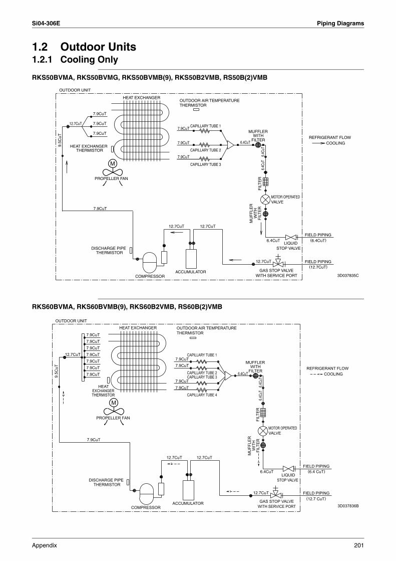
Si04-306E Piping Diagrams
1.2 Outdoor Units1.2.1 Cooling Only
RKS50BVMA, RKS50BVMG, RKS50BVMB(9), RKS50B2VMB, RS50B(2)VMB
RKS60BVMA, RKS60BVMB(9), RKS60B2VMB, RS60B(2)VMB
OUTDOOR UNIT
9.5C
uT
12.7CuT
HEAT EXCHANGERTHERMISTOR
7.9CuT
DISCHARGE PIPE
7.9CuT
7.9CuT
7.9CuT
THERMISTOR
PROPELLER FAN
M
HEAT EXCHANGER
COMPRESSOR
12.7CuT
OUTDOOR AIR TEMPERATURE
7.9CuT
7.9CuT
7.9CuT
THERMISTOR
ACCUMULATOR
CAPILLARY TUBE 2
CAPILLARY TUBE 1
CAPILLARY TUBE 3
12.7CuT
6.4CuT
MUFFLER
FILTER
MU
FF
LER
WITH
12.7CuT
WIT
HF
ILT
ER
WITH SERVICE PORT
6.4CuT
FIL
TE
R6.
4CuT
6.4C
uT
GAS STOP VALVE
VALVEMOTOR OPERATED
STOP VALVELIQUID
FIELD PIPING
FIELD PIPING
REFRIGERANT FLOW
(12.7CuT)
(6.4CuT)
COOLING
3D037835C
OUTDOOR UNIT
9.5C
uT
12.7CuT
7.9CuT
7.9CuT7.9CuT
7.9CuT
7.9CuT
7.9CuT
7.9CuT
7.9CuT
DISCHARGE PIPE
THERMISTOREXCHANGER
THERMISTOR
HEAT
PROPELLER FAN
M
HEAT EXCHANGER
COMPRESSOR
12.7CuT
OUTDOOR AIR TEMPERATURE
7.9CuT
7.9CuT
7.9CuT
7.9CuT
THERMISTOR
ACCUMULATOR
CAPILLARY TUBE 4
CAPILLARY TUBE 2
CAPILLARY TUBE 1
CAPILLARY TUBE 3
12.7CuT
6.4CuT
MUFFLER
FILTER
MU
FFLE
R
WITH
12.7CuT
WIT
HFI
LTER
WITH SERVICE PORT
FILT
ER
6.4CuT
6.4Cu
T6.4
CuT
GAS STOP VALVE
VALVEMOTOR OPERATED
STOP VALVELIQUID
FIELD PIPING
FIELD PIPING
REFRIGERANT FLOW
(6.4 CuT)
(12.7 CuT)
COOLING
3D037836B
Appendix 201
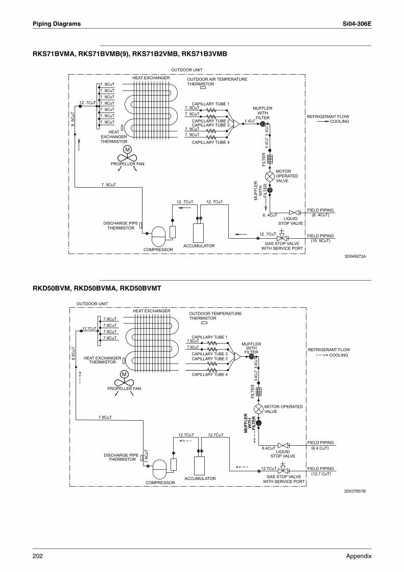
Piping Diagrams Si04-306E
RKS71BVMA, RKS71BVMB(9), RKS71B2VMB, RKS71B3VMB
RKD50BVM, RKD50BVMA, RKD50BVMT
OUTDOOR UNIT9.
5C
uT
12. 7CuT
7. 9CuT
7. 9CuT
7. 9CuT7. 9CuT
7. 9CuT7. 9CuT
7. 9CuT7. 9CuT
DISCHARGE PIPETHERMISTOR
HEATEXCHANGERTHERMISTOR
PROPELLER FAN
HEAT EXCHANGER
COMPRESSOR
12. 7CuT
OUTDOOR AIR TEMPERATURETHERMISTOR
7. 9CuT7. 9CuT
7. 9CuT7. 9CuT
ACCUMULATOR
CAPILLARY TUBE 4
CAPILLARY TUBE 2CAPILLARY TUBE 3
CAPILLARY TUBE 1
12. 7CuT
6. 4CuT
MUFFLERWITH
FILTER
MU
FFLE
RW
ITH
FILT
ER
12. 7CuT
FILT
ER
6. 4CuT
6. 4C
uT6.
4CuT
GAS STOP VALVEWITH SERVICE PORT
MOTOR OPERATEDVALVE
LIQUIDSTOP VALVE
FIELD PIPING(6. 4CuT)
FIELD PIPING(15. 9CuT)
REFRIGERANT FLOWCOOLING
M
3D049272A
OUTDOOR UNIT
9.5C
uT
12.7CuT
HEAT EXCHANGERTHERMISTOR
7.9CuT
7.9CuT7.9CuT
7.9CuT7.9CuT
DISCHARGE PIPE THERMISTOR
PROPELLER FAN
M
HEAT EXCHANGER
COMPRESSOR
7.9C
uT
12.7CuT
ACCUMULATOR
OUTDOOR TEMPERATURE
7.9CuT7.9CuT
THERMISTOR
CAPILLARY TUBE 2CAPILLARY TUBE 3
CAPILLARY TUBE 4
CAPILLARY TUBE 1
12.7CuT
MUFFLER
FILTERWITH
MU
FFLE
RM
UFF
LER
WIT
HW
ITH
FILT
ERFI
LTER
FILT
ER6.4
CuT
6.4Cu
T
MOTOR OPERATED
12.7CuT
6.4CuT
WITH SERVICE PORT
VALVE
GAS STOP VALVE
STOP VALVELIQUID
FIELD PIPING
FIELD PIPING
REFRIGERANT FLOW
(12.7 CuT)
(6.4 CuT)
COOLING
3D037851B
202 Appendix
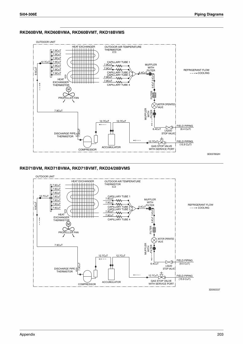
Si04-306E Piping Diagrams
RKD60BVM, RKD60BVMA, RKD60BVMT, RKD18BVMS
RKD71BVM, RKD71BVMA, RKD71BVMT, RKD24/28BVMS
OUTDOOR UNIT
9.5C
uT
12.7CuT
7.9CuT
7.9CuT
7.9CuT
7.9CuT
7.9CuT
7.9CuT
7.9CuT
7.9CuT
HEAT EXCHANGER THERMISTOR
PROPELLER FAN
HEAT EXCHANGER OUTDOOR AIR TEMPERATURETHERMISTOR
7.9CuT
7.9CuT
7.9CuT
7.9CuT
CAPILLARY TUBE 4
CAPILLARY TUBE 2
CAPILLARY TUBE 1
CAPILLARY TUBE 36.4CuT
MUFFLERWITH
FILTER
FIL
TE
R6.
4CuT
6.4C
uT
MOTOR OPERATEDVALVE
MU
FF
LER
WIT
HF
ILT
ER
12.7CuT
6.4CuT
GAS STOP VALVEWITH SERVICE PORT
LIQUIDSTOP VALVE
FIELD PIPING
FIELD PIPING
(6.4 CuT)
(15.9 CuT)
REFRIGERANT FLOWCOOLING
M
DISCHARGE PIPE THERMISTOR 7.
9CuT
COMPRESSOR
12.7CuT
ACCUMULATOR
12.7CuT
3D037852H
OUTDOOR UNIT
9.5C
uT
12.7CuT
7.9CuT
7.9CuT
7.9CuT
7.9CuT
7.9CuT
7.9CuT
7.9CuT
7.9CuT
DISCHARGE PIPETHERMISTOR
HEATEXCHANGERTHERMISTOR
PROPELLER FAN
M
HEAT EXCHANGER
7.9C
uT
COMPRESSOR
12.7CuT
OUTDOOR AIR TEMPERATURETHERMISTOR
7.9CuT
7.9CuT7.9CuT
7.9CuT
ACCUMULATOR
CAPILLARY TUBE 4
CAPILLARY TUBE 2CAPILLARY TUBE 3
CAPILLARY TUBE 1
12.7CuT
6.4CuT
MUFFLERWITH
FILTER
MU
FFLE
RW
ITH
FILT
ER
12.7CuT
FILT
ER
6.4CuT
6.4Cu
T6.4
CuT
GAS STOP VALVEWITH SERVICE PORT
MOTOR OPERATEDVALVE
LIQUIDSTOP VALVE
FIELD PIPING(15.9 CuT)
FIELD PIPING(9.5 CuT)
REFRIGERANT FLOWCOOLING
3D050337
Appendix 203
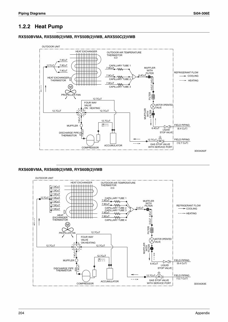
Piping Diagrams Si04-306E
1.2.2 Heat Pump
RXS50BVMA, RXS50B(2)VMB, RYS50B(2)VMB, ARXS50C(2)VMB
RXS60BVMA, RXS60B(2)VMB, RYS60B(2)VMB
OUTDOOR UNIT
12.7CuT
HEAT EXCHANGERTHERMISTOR
12.7CuT
DISCHARGE PIPETHERMISTOR
7.9CuT
7.9CuT
7.9CuT
PROPELLER FAN
MUFFLER
7.9Cu
T7.
9CuT
VALVEFOUR WAY
ON : HEATING
COMPRESSOR
12.7CuT
12.7CuT
12.7CuT
ACCUMULATOR
HEAT EXCHANGER OUTDOOR AIR TEMPERATURETHERMISTOR
7.9CuT
7.9CuT
7.9CuTCAPILLARY TUBE 2
CAPILLARY TUBE 1
CAPILLARY TUBE 3
6.4CuT
MUFFLERWITH
FILTER
MU
FFLE
RW
ITH
FILT
ERFI
LTER
6.4Cu
T6.4
CuT
MOTOR OPERATEDVALVE
REFRIGERANT FLOWCOOLING
HEATING
12.7CuT
6.4CuT
GAS STOP VALVEWITH SERVICE PORT
LIQUIDSTOP VALVE
FIELD PIPING
FIELD PIPING(12.7 CuT)
(6.4 CuT)
M
3D034262F
OUTDOOR UNIT
12.7CuT
12.7CuT
7.9CuT7.9CuT7.9CuT7.9CuT
7.9CuT
7.9CuT7.9CuT
DISCHARGE PIPE
THERMISTOREXCHANGER
THERMISTOR
HEAT
PROPELLER FAN
MUFFLER
M
HEAT EXCHANGER
7.9Cu
T7.
9CuT
VALVEFOUR WAY
COMPRESSOR
ON:HEATING
12.7CuT
12.7CuT
12.7CuT
OUTDOOR AIR TEMPERATURE
7.9CuT
7.9CuT7.9CuT
7.9CuT
THERMISTOR
ACCUMULATOR
CAPILLARY TUBE 4
CAPILLARY TUBE 2
CAPILLARY TUBE 1
CAPILLARY TUBE 36.4CuT
MUFFLER
FILTER
MU
FFLE
R
WITH
12.7CuT
WIT
HFI
LTER
WITH SERVICE PORT
6.4CuT
FILT
ER6.4
CuT
6.4Cu
T
GAS STOP VALVE
VALVEMOTOR OPERATED
STOP VALVELIQUID
FIELD PIPING
FIELD PIPING
REFRIGERANT FLOW
(6.4 CuT)
(12.7 CuT)
COOLING
HEATING
3D034263E
204 Appendix
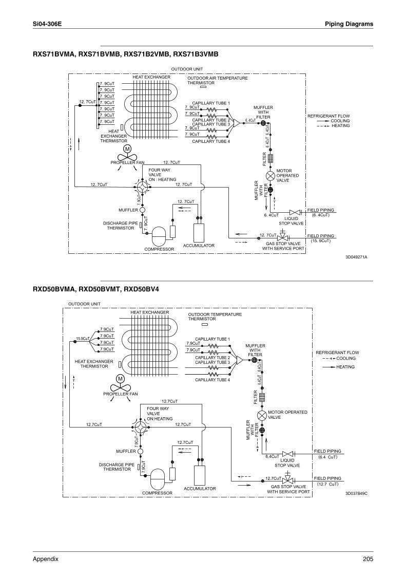
Si04-306E Piping Diagrams
RXS71BVMA, RXS71BVMB, RXS71B2VMB, RXS71B3VMB
RXD50BVMA, RXD50BVMT, RXD50BV4
OUTDOOR UNIT
12. 7CuT
12. 7CuT
7. 9CuT
7. 9CuT
7. 9CuT7. 9CuT
7. 9CuT
7. 9CuT7. 9CuT
DISCHARGE PIPETHERMISTOR
MUFFLER
M
HEAT EXCHANGER
7. 9C
uT7.
9C
uT
FOUR WAYVALVEON : HEATING
COMPRESSOR
12. 7CuT
12. 7CuT
12. 7CuT
OUTDOOR AIR TEMPERATURETHERMISTOR
7. 9CuT7. 9CuT
7. 9CuT7. 9CuT
ACCUMULATOR
CAPILLARY TUBE 4
CAPILLARY TUBE 2CAPILLARY TUBE 3
CAPILLARY TUBE 1
12. 7CuT
6. 4CuT
GAS STOP VALVEWITH SERVICE PORT
LIQUIDSTOP VALVE
FIELD PIPING(6. 4CuT)
FIELD PIPING(15. 9CuT)
HEATEXCHANGERTHERMISTOR
PROPELLER FAN
6. 4CuT
MUFFLERWITH
FILTER
MU
FFLE
RW
ITH
FILT
ERFI
LTER
6. 4C
uT6.
4CuT
MOTOR OPERATEDVALVE
REFRIGERANT FLOWCOOLINGHEATING
3D049271A
OUTDOOR UNIT
15.9CuT
HEAT EXCHANGERTHERMISTOR
12.7CuT
DISCHARGE PIPE
7.9CuT
7.9CuT7.9CuT
7.9CuT
THERMISTOR
PROPELLER FAN
M
MUFFLER
HEAT EXCHANGER
7.9C
uT7.
9CuT
VALVEFOUR WAY
ON:HEATING
COMPRESSOR
12.7CuT
12.7CuT
12.7CuT
CAPILLARY TUBE 3CAPILLARY TUBE 2
OUTDOOR TEMPERATURE
7.9CuT7.9CuT
THERMISTOR
ACCUMULATOR
CAPILLARY TUBE 4
CAPILLARY TUBE 1MUFFLER
FILTER
MU
FFLE
R
WITH
WIT
HFI
LTER
FILT
ER6.4
CuT
6.4Cu
T
12.7CuT
6.4CuT
VALVEMOTOR OPERATED
WITH SERVICE PORTGAS STOP VALVE
STOP VALVELIQUID
FIELD PIPING
FIELD PIPING
REFRIGERANT FLOW
(6.4 CuT)
(12.7 CuT)
COOLING
HEATING
3D037849C
Appendix 205
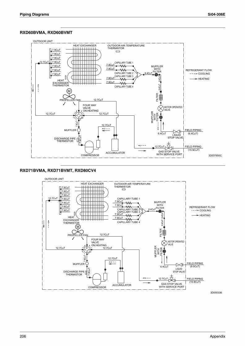
Piping Diagrams Si04-306E
RXD60BVMA, RXD60BVMT
RXD71BVMA, RXD71BVMT, RXD80CV4
12.7CuT
12.7CuT
7.9CuT7.9CuT
7.9CuT7.9CuT
7.9CuT
7.9CuT
7.9CuT
DISCHARGE PIPE
THERMISTOREXCHANGER
THERMISTOR
HEAT
PROPELLER FAN
MUFFLER
HEAT EXCHANGER
7.9Cu
T7.
9CuT
VALVEFOUR WAY
COMPRESSOR
ON:HEATING
12.7CuT
12.7CuT
12.7CuT
OUTDOOR AIR TEMPERATURE
7.9CuT
7.9CuT
7.9CuT
7.9CuT
THERMISTOR
ACCUMULATOR
CAPILLARY TUBE 4
CAPILLARY TUBE 2
CAPILLARY TUBE 1
CAPILLARY TUBE 36.4CuT
MUFFLER
FILTER
MU
FFLE
R
WITH
12.7CuT
WIT
HFI
LTER
WITH SERVICE PORTFI
LTER
6.4CuT
6.4Cu
T6.4
CuT
GAS STOP VALVE
VALVEMOTOR OPERATED
STOP VALVELIQUID
FIELD PIPING
FIELD PIPING
REFRIGERANT FLOW
(15.9CuT)
(6.4CuT)
COOLING
HEATING
M
OUTDOOR UNIT
3D037850C
OUTDOOR UNIT
12.7CuT
12.7CuT
7.9CuT
7.9CuT
7.9CuT
7.9CuT
7.9CuT
7.9CuT
7.9CuT
DISCHARGE PIPETHERMISTOR
HEATEXCHANGERTHERMISTOR
PROPELLER FAN
MUFFLER
M
HEAT EXCHANGER
7.9C
uT
7.9C
uT
FOUR WAYVALVEON:HEATING
COMPRESSOR
12.7CuT
12.7CuT
12.7CuT
OUTDOOR AIR TEMPERATURETHERMISTOR
7.9CuT
7.9CuT
7.9CuT
7.9CuT
ACCUMULATOR
CAPILLARY TUBE 4
CAPILLARY TUBE 2CAPILLARY TUBE 3
CAPILLARY TUBE 1
6.4CuT
MUFFLERWITH
FILTER
MU
FFLE
RW
ITH
FILT
ER
12.7CuT
FILT
ER
6.4CuT
6.4Cu
T6.4
CuT
GAS STOP VALVEWITH SERVICE PORT
MOTOR OPERATEDVALVE
LIQUIDSTOP VALVE
FIELD PIPING(9.5CuT)
FIELD PIPING(15.9CuT)
REFRIGERANT FLOWCOOLING
HEATING
3D050338
206 Appendix
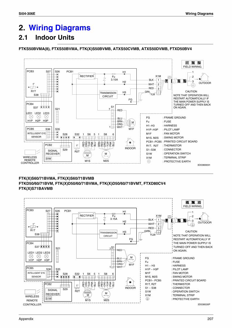
Si04-306E Wiring Diagrams
2. Wiring Diagrams2.1 Indoor Units
FTKS50BVMA(8), FTXS50BVMA, FTK(X)S50BVMB, ATXS50CVMB, ATXS50DVMB, FTXD50BV4
FTK(X)S60/71BVMA, FTK(X)S60/71BVMBFTKD50/60/71BVM, FTK(X)D50/60/71BVMA, FTK(X)D50/60/71BVMT, FTXD80CV4FTK(X)S71BAVMB
CONTROLLER
WIRELESSREMOTE
PCB4
PCB3
PCB5
INTELLIGENT EYE
LED1
H1P
R1T
SENSOR
t°
S37
S38
LED2
H2P
LED3
H3P
PCB2
S27
S36
S1W
RECEIVERSIGNAL
S26
S35
S21
S29
S28
PCB1
R2T
S32
t°
~RECTIFIER
1
RE
D
M1S
M
S6
OR
GY
LW
~
PN
K
5
BLU
1
TRANSMISSION
BR
NR
ED
CIRCUIT
M2S
S8
M
OR
GY
LW7
1
3.15A
S1P
NK
6
Fu
BLU
WHT
BRN
RED
BLU
ORG
H2
H3
H1
INDOOR
M1F
FG
M
GRN
FG
Fu
H1~H3
H1P~H3P
M1F
M1S, M2SPCB1~PCB5
R1T, R2T
S1~S38
S1W
X1M
WHT
RED
/
BLK
YLW
X1M
3
2
1
: SWING MOTOR
: THERMISTOR
: PROTECTIVE EARTH
THE MAIN POWER SUPPLY IS
ON AGAIN.TURNED OFF AND THEN BACK
NOTE THAT OPERATION WILLRESTART AUTOMATICALLY IF
FIELD WIRING.
CAUTION
3
2
1
OUTDOOR
: FRAME GROUND
: FUSE
: HARNESS
: PILOT LAMP
: FAN MOTOR
: PRINTED CIRCUIT BOARD
: CONNECTOR
: OPERATION SWITCH
: TERMINAL STRIP
3D038065H
CONTROLLER
WIRELESS
REMOTE
PCB4
PCB3
PCB5
INTELLIGENT EYE
LED1
H1P
R1T
SENSOR
t
S37
S38
°
LED2
H2P
LED3
H3P
PCB2
S27
S36
S1W
RECEIVER
SIGNAL
S26
S35
S21
S29
S28
PCB1
R2T
S32
t°
~ RECTIFIER
1
RE
D
M1S
M
S6
OR
GY
LW
~
PN
K
5
BLU
1
TRANSMISSION
BR
NR
ED
CIRCUIT
M2S
S8
M
OR
GY
LW
7
1
3.15A
S1
PN
K
6
Fu
BLU
WHT
BRN
RED
BLU
ORG
H2
H3
H1
INDOOR
FG
M1F
M
GRN
R1T, R2T
M1S, M2SPCB1~ PCB5
WHT
RED
/
BLK
Fu
M1F
H1 ~ H3
S1 ~ S38
H1P ~ H3P
FG
YLW
X1MS1W
X1M
3
2
1
: PROTECTIVE EARTH
THE MAIN POWER SUPPLY IS
ON AGAIN.TURNED OFF AND THEN BACK
NOTE THAT OPERATION WILLRESTART AUTOMATICALLY IF
FIELD WIRING.
CAUTION
3
2
1
OUTDOOR
: FRAME GROUND: FUSE: HARNESS: PILOT LAMP: FAN MOTOR: SWING MOTOR: PRINTED CIRCUIT BOARD: THERMISTOR: CONNECTOR: OPERATION SWITCH: TERMINAL STRIP
3D038530P
Appendix 207
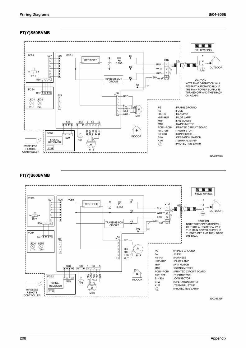
Wiring Diagrams Si04-306E
FT(Y)S50BVMB
FT(Y)S60BVMB
M
M
H2P
LED2
RECTIFIER
S1W
Fu3.15A
INDOOR
LED1
H1P
OUTDOOR
SIGNALRECEIVER
TRANSMISSIONCIRCUIT
2
3
1
X1M
FIELD WIRING.
R2T
YLW/
ORG
S1O
RG
H3
BLK
1
RED
1
GRN
PN
K
M1F
H2
1
BRNBLU
RE
D
PCB3
S21
5
BLU
WHT
WHT
PCB4Y
LW
S28
PCB1S26
2
M1S
R1T
H1
S32 S6
7
WIRELESSREMOTE
CONTROLLER
S29
FG
t°
S37
t°
PCB2
3
S27
RED
S38
THE MAIN POWER SUPPLY IS
ON AGAIN.TURNED OFF AND THEN BACK
NOTE THAT OPERATION WILLRESTART AUTOMATICALLY IF
CAUTION
FG Fu
H1P~H2P M1F M1SPCB1~PCB4R1T, R2T S1~S38 S1W X1M
: SWING MOTOR
: THERMISTOR
: PROTECTIVE EARTH: TERMINAL STRIP : OPERATION SWITCH: CONNECTOR
: PRINTED CIRCUIT BOARD
: FAN MOTOR: PILOT LAMP
: FUSE: FRAME GROUND
H1~H3 : HARNESS
~ ~
3D038466C
M
2
3
1
X1M
OUTDOOR
INDOOR
LED1
H1P
RECTIFIER
FIELD WIRING.
S1W
Fu3.15A
TRANSMISSIONCIRCUIT
SIGNALRECEIVER
LED2
H2P
WHT
R2T
S21
51
3
BRNM1F
GRN
WIRELESSREMOTE
CONTROLLER
H1
S6S28
PCB4
S29
S26
OR
G
M
2
S1
PN
K
M1S
S37
YLW
H3
S27
BLK
PCB3
t°
FG
YLW
ORG
PCB1
H2
R1T
7
RE
D
RED
PCB2 BLU
BLU
t°
RED
S32
WHT
S38
1
/
1
M1S
R1T, R2T
FuH1~H3
M1FH1P~H2P
S1~S38
FG
X1MS1W
PCB1~PCB4
: PROTECTIVE EARTH
: THERMISTOR
: SWING MOTOR
THE MAIN POWER SUPPLY IS
ON AGAIN.TURNED OFF AND THEN BACK
NOTE THAT OPERATION WILLRESTART AUTOMATICALLY IF
CAUTION
: FRAME GROUND
: HARNESS: FUSE
: PILOT LAMP: FAN MOTOR
: PRINTED CIRCUIT BOARD
: CONNECTOR: OPERATION SWITCH: TERMINAL STRIP
~ ~
3D038532F
208 Appendix
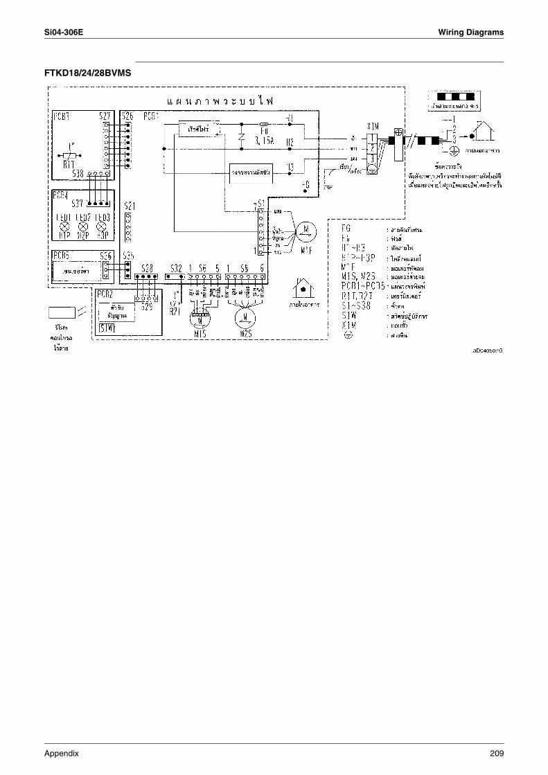
Si04-306E Wiring Diagrams
FTKD18/24/28BVMS
Appendix 209
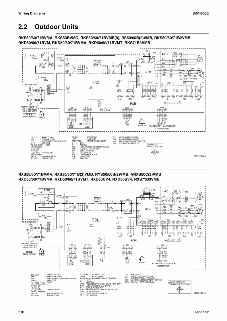
Wiring Diagrams Si04-306E
2.2 Outdoor Units
RKS50/60/71BVMA, RKS50BVMG, RKS50/60/71BVMB(9), RS50/60B(2)VMB, RKS50/60/71B2VMBRKD50/60/71BVM, RKD50/60/71BVMA, RKD50/60/71BVMT, RKS71B3VMB
RXS50/60/71BVMA, RXS50/60/71B(2)VMB, RYS50/60B(2)VMB, ARXS50C(2)VMBRXD50/60/71BVMA, RXD50/60/71BVMT, RXD80CV4, RXD50BV4, RXS71B3VMB
FIELD WIRING
TO INDOOR UNIT
POWER SUPPLY~50Hz 220-240V ~60Hz 220-230V
NL
23
1
V2~V5 : VARISTOR
MRC/W : MAGNETIC RELAY
Y2E : ELECTRONIC EXPANSION VALVE
E, AC1, AC2
Z1C, Z2C : FERRITE CORE
MRM10, MRM20
R1T~R3T : THERMISTOR
X1M : TERMINAL STRIP
H1, H2, HLL1, L2, X11A : CONNECTOR
HE1, HE2, HAC1
GRN
FU1, FU2. FU201 : FUSE
YLW
HL
indoor
HE2
GRN
30A
FU1
BLK
PCB2
YLW
SA1
V3
X1M
23
1
HAC1
HE1GRN
WHT
BLK
RED
YLW
AC2
AC1E
S10
V2
1
1
3
LEDAS1W
1
BLU
S52
S51
BLU
S4W : LOCAL SETTING SW (SW4)
S2~S102 : CONNECTORLEDA : PILOT LAMP
L : LIVEN : NEUTRALS1W : FORCED OPERATION ON/OFF SW (SW1)
PCB1, PCB2 : PRINTED CIRCUIT BOARD
L1R : REACTOR
DB1 : DIODE BRIDGESA1 : SURGE ARRESTER
M1C : COMPRESSOR MOTORM1F : FAN MOTOR
BLU
BLU
5
5
BLU
S2
1
1
RED
S102
S4W
S101
BLK
WHT
5
5
V5
GRN
MRM20
MRM10
FU23.15A
1
MR
CW
3S80
CT1 H2
H1
SPM : SYSTEM POWER MODULE
CT1 : CURRENT TRANSFORMERQ1L : OVERLOAD PROTECTOR
MID : MOLDED INTER CONNECT DEVICE
t°
YLW
BLU
R12T
1
BLK
S91
Z2C
BLK
3
1
WHT
YLW
Y2E
S20
~
~
DB1
M
1
ORG
BLK
+
BLU
S32
BLK
BRN
PCB1
6
BLK
RED
BLK
RED
BLK
5
BLK
CN11
outdoor
5
1
+
-
ORGL1
1
1
BLK
BLK
SPM
BLK
TERMINALS OF THE COMP.ASSIGNMENTS OF
S31
BLK
CN14
BLK
ORGL2
VBL
K
L1R
Z1C
BLK
W
U
BLK
(OUTDOOR)
P2
9
N1P1
W
UV
BLK
10
R3T
N
1
(CONDENSER)
BLU
t°
BLU
R2T
S90
GRY
1
1
(DISCHARGE)
TB4
TB6TB5
P2
N1
P1
WHT
t°
GRY
MID
R1T
S6
ORG
BLK
6
BRN
+
BLK
t°
S72
S711
BLU
+ +
8
8
FU201
3.15A
RED
1
1
S70
BRN
W
V
U
N
7
1
8
RED
S33
S34
YLW
WHT
BLU
RED
ORGBRN
BLU
BRNRED
YLW
X11A
10
10
BLU
YLW
BRNBLU
RED
1
GRY
V
S40
1
3
M1F
M1C
M
M
BLK
4
W
U
Q1L
BLK
N
3D037866J
M
M
M
Z1C, Z2CX1MY2EV2~V5FU1, FU2, FU201HE1, HE2, HAC1E, AC1, C2H1, H2, HLL1, L2, X11AMRM10, MRM20MRC/WR1T~R3T
: FERRITE CORE: TERMINAL STRIP: ELECTRONIC EXPANSION VALVE: VARISTOR: FUSE
: CONNECTOR
: MAGNETIC RELAY: THERMISTOR
S2~S102LEDAPCB1, PCB2LNS1WS4WSA1Y1RDB1M1CM1F
: LIVE: NEUTRAL: FORCED OPERATION ON/OFF SW (SW1): LOCAL SETTING SW (SW4): SURGE ARRESTER: REVERSING SOLENOID VALVE COIL: DIODE BRIDGE: COMPRESSOR MOTOR: FAN MOTOR
: CONNECTOR: PILOT LAMP: PRINTED CIRCUIT BOARD
L1RQ1LCT1MIDSPM
: REACTOR: OVERLOAD PROTECTOR: CURRENT TRANSFORMER: MOLDED INTER CONNECT DEVICE: SYSTEM POWER MODULE ASSIGNMENTS OF
TERMINALS OF THE COMP.
V
W
U
N
(OUTDOOR)R3T
(CONDENSER)
R2T(DISCHARGE)R1T
1
BLU
t°
BLU
S90
GRY
t°
GRY BLK
6
t°
BLK
Y2E outdoor
1
LEDAS1W
S52 5
S4W
Y1RS21 S102 5
BLU
BLU
BLU
BLU
BLU
RED
BLK
WHT
GRN
1 S51 5 1 S1015
BLK
BLK
1 3S80
MR
CW
V5S10
3
1
X1M
23
1
RED
TO INDOOR UNIT
POWER SUPPLY~50Hz 220-240V~60Hz 220-230V
N
L
23
1
FIELD WIRING indoor
GRNYLW
GRNYLW
HL
HE2
30A
FU1
BLK
PCB2
SA1V3
WHT
BLK
YLW
AC2
AC1E
V2
HAC1
HE1GRN
MRM20
MRM10
CT1H2
H1YLW
BLU
Z2C
FU23.15A
~
~
DB1+
-
RED
BLK
+
-
ORGL1
SPM
ORGL2
P2N1P1
WVUCN11
5
1
1 CN14 10t°
R12T
1S91
3 1 S32 5
BLK
BLK
BLK
BLK
BLK
BLK
BLK
BLK
BLK
BLK
BLK
BLK
BLK
BLK
BLK
BLK
WHT
ORG
BRN
BLU
RED
BRN
WHT
YLW
ORG BL
UBR
NRE
D
1 S20
PCB1
6
1 S31 9 1
S6
S711
8 1
8S33
RED
YLW
BLU
GRY
BLK
BLK
10 1S40
4
1 S72 8 1 S34 10 Q1L
L1R
Z1C
TB6
TB4TB5
P2N1
P1
MID
+ + +
FU201
3.15A
S70
WVUN
7
1 WHT
RED
BRNORG
BLU
YLWBLU
REDBRN
X11A
YLW
BRNBLU
RED
M1F
M1C
V
W
UN
3
1
3D037854J
210 Appendix
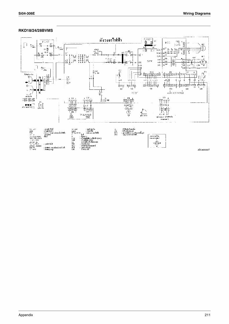
Si04-306E Wiring Diagrams
RKD18/24/28BVMS
Appendix 211
Wiring Diagrams Si04-306E
212 Appendix
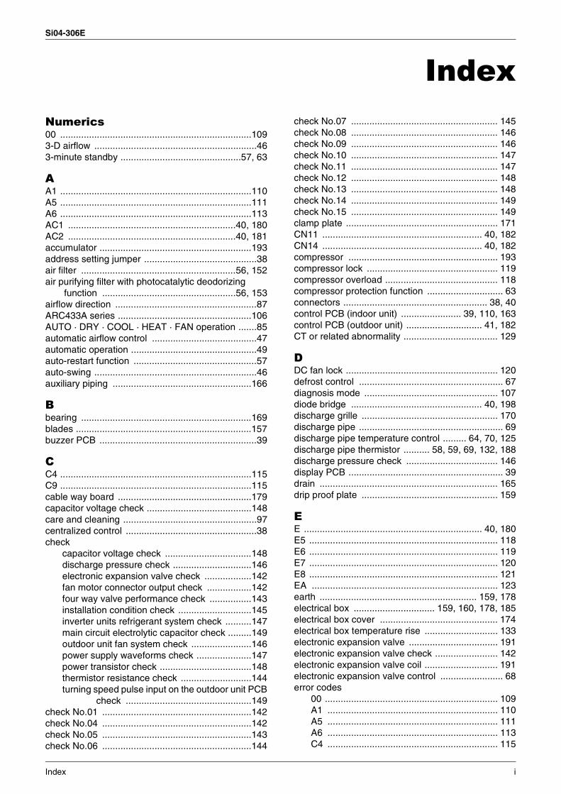
Si04-306E
IndexNumerics00 .........................................................................1093-D airflow ..............................................................463-minute standby ..............................................57, 63
AA1 .........................................................................110A5 .........................................................................111A6 .........................................................................113AC1 ................................................................40, 180AC2 ................................................................40, 181accumulator ..........................................................193address setting jumper ...........................................38air filter ...........................................................56, 152air purifying filter with photocatalytic deodorizing
function ...................................................56, 153airflow direction ......................................................87ARC433A series ...................................................106AUTO · DRY · COOL · HEAT · FAN operation .......85automatic airflow control ........................................47automatic operation ................................................49auto-restart function ...............................................57auto-swing ..............................................................46auxiliary piping .....................................................166
Bbearing .................................................................169blades ...................................................................157buzzer PCB ............................................................39
CC4 .........................................................................115C9 .........................................................................115cable way board ...................................................179capacitor voltage check ........................................148care and cleaning ...................................................97centralized control ..................................................38check
capacitor voltage check .................................148discharge pressure check ..............................146electronic expansion valve check ..................142fan motor connector output check .................142four way valve performance check ................143installation condition check ............................145inverter units refrigerant system check ..........147main circuit electrolytic capacitor check .........149outdoor unit fan system check .......................146power supply waveforms check .....................147power transistor check ...................................148thermistor resistance check ...........................144turning speed pulse input on the outdoor unit PCB
check ................................................149check No.01 .........................................................142check No.04 .........................................................142check No.05 .........................................................143check No.06 .........................................................144
check No.07 ........................................................ 145check No.08 ........................................................ 146check No.09 ........................................................ 146check No.10 ........................................................ 147check No.11 ........................................................ 147check No.12 ........................................................ 148check No.13 ........................................................ 148check No.14 ........................................................ 149check No.15 ........................................................ 149clamp plate .......................................................... 171CN11 ............................................................. 40, 182CN14 ............................................................. 40, 182compressor ......................................................... 193compressor lock .................................................. 119compressor overload ........................................... 118compressor protection function ............................. 63connectors ....................................................... 38, 40control PCB (indoor unit) ....................... 39, 110, 163control PCB (outdoor unit) ............................. 41, 182CT or related abnormality .................................... 129
DDC fan lock .......................................................... 120defrost control ....................................................... 67diagnosis mode ................................................... 107diode bridge .................................................. 40, 198discharge grille .................................................... 170discharge pipe ....................................................... 69discharge pipe temperature control ......... 64, 70, 125discharge pipe thermistor .......... 58, 59, 69, 132, 188discharge pressure check ................................... 146display PCB ........................................................... 39drain .................................................................... 165drip proof plate .................................................... 159
EE .................................................................... 40, 180E5 ........................................................................ 118E6 ........................................................................ 119E7 ........................................................................ 120E8 ........................................................................ 121EA ....................................................................... 123earth ............................................................ 159, 178electrical box ............................... 159, 160, 178, 185electrical box cover ............................................. 174electrical box temperature rise ............................ 133electronic expansion valve .................................. 191electronic expansion valve check ........................ 142electronic expansion valve coil ............................ 191electronic expansion valve control ........................ 68error codes
00 .................................................................. 109A1 ................................................................. 110A5 ................................................................. 111A6 ................................................................. 113C4 ................................................................. 115
Index i
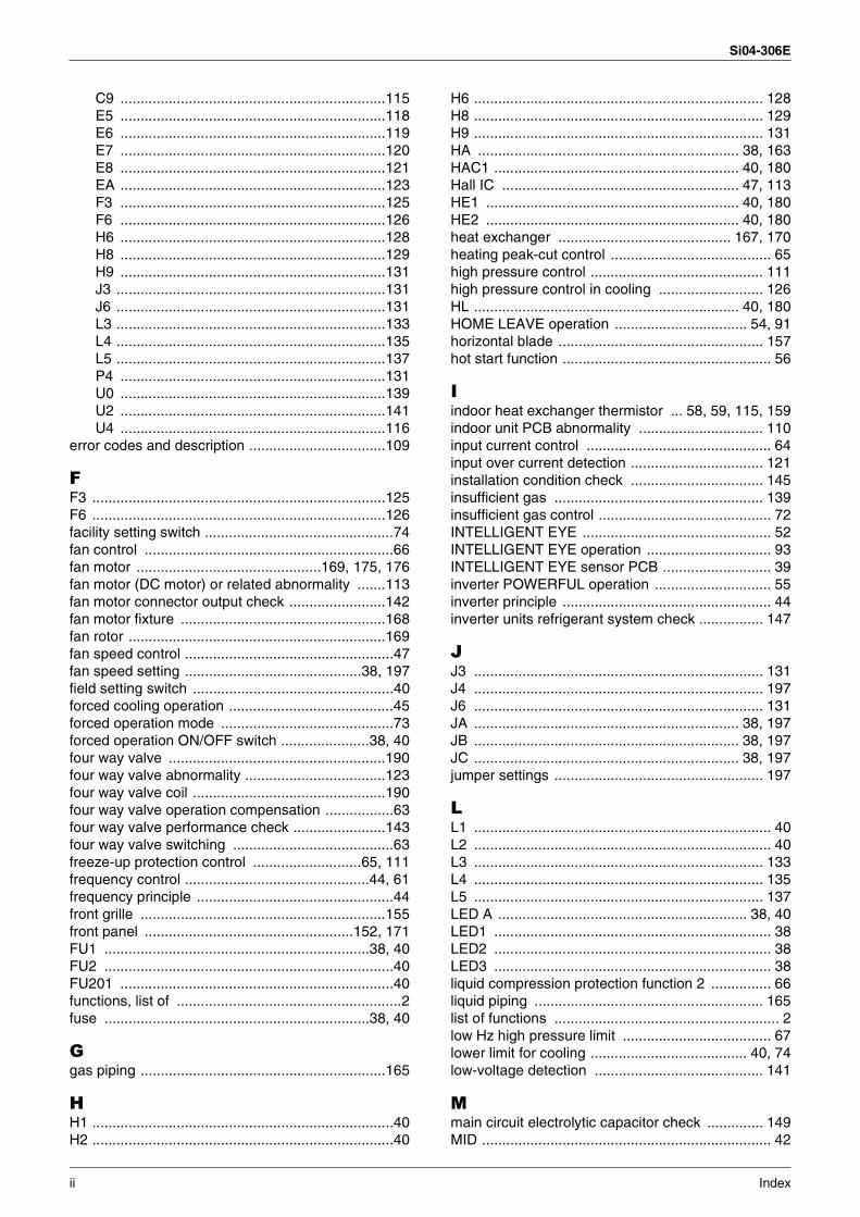
Si04-306E
C9 ..................................................................115E5 ..................................................................118E6 ..................................................................119E7 ..................................................................120E8 ..................................................................121EA ..................................................................123F3 ..................................................................125F6 ..................................................................126H6 ..................................................................128H8 ..................................................................129H9 ..................................................................131J3 ...................................................................131J6 ...................................................................131L3 ...................................................................133L4 ...................................................................135L5 ...................................................................137P4 ..................................................................131U0 ..................................................................139U2 ..................................................................141U4 ..................................................................116
error codes and description ..................................109
FF3 .........................................................................125F6 .........................................................................126facility setting switch ...............................................74fan control ..............................................................66fan motor ..............................................169, 175, 176fan motor (DC motor) or related abnormality .......113fan motor connector output check ........................142fan motor fixture ...................................................168fan rotor ................................................................169fan speed control ....................................................47fan speed setting ............................................38, 197field setting switch ..................................................40forced cooling operation .........................................45forced operation mode ...........................................73forced operation ON/OFF switch ......................38, 40four way valve ......................................................190four way valve abnormality ...................................123four way valve coil ................................................190four way valve operation compensation .................63four way valve performance check .......................143four way valve switching ........................................63freeze-up protection control ...........................65, 111frequency control ..............................................44, 61frequency principle .................................................44front grille .............................................................155front panel ....................................................152, 171FU1 ..................................................................38, 40FU2 ........................................................................40FU201 ....................................................................40functions, list of ........................................................2fuse ..................................................................38, 40
Ggas piping .............................................................165
HH1 ...........................................................................40H2 ...........................................................................40
H6 ........................................................................ 128H8 ........................................................................ 129H9 ........................................................................ 131HA ................................................................. 38, 163HAC1 ............................................................. 40, 180Hall IC ........................................................... 47, 113HE1 ............................................................... 40, 180HE2 ............................................................... 40, 180heat exchanger ........................................... 167, 170heating peak-cut control ........................................ 65high pressure control ........................................... 111high pressure control in cooling .......................... 126HL .................................................................. 40, 180HOME LEAVE operation ................................. 54, 91horizontal blade ................................................... 157hot start function .................................................... 56
Iindoor heat exchanger thermistor ... 58, 59, 115, 159indoor unit PCB abnormality ............................... 110input current control .............................................. 64input over current detection ................................. 121installation condition check ................................. 145insufficient gas .................................................... 139insufficient gas control ........................................... 72INTELLIGENT EYE ............................................... 52INTELLIGENT EYE operation ............................... 93INTELLIGENT EYE sensor PCB ........................... 39inverter POWERFUL operation ............................. 55inverter principle .................................................... 44inverter units refrigerant system check ................ 147
JJ3 ........................................................................ 131J4 ........................................................................ 197J6 ........................................................................ 131JA .................................................................. 38, 197JB .................................................................. 38, 197JC .................................................................. 38, 197jumper settings .................................................... 197
LL1 .......................................................................... 40L2 .......................................................................... 40L3 ........................................................................ 133L4 ........................................................................ 135L5 ........................................................................ 137LED A .............................................................. 38, 40LED1 ..................................................................... 38LED2 ..................................................................... 38LED3 ..................................................................... 38liquid compression protection function 2 ............... 66liquid piping ......................................................... 165list of functions ........................................................ 2low Hz high pressure limit ..................................... 67lower limit for cooling ....................................... 40, 74low-voltage detection .......................................... 141
Mmain circuit electrolytic capacitor check .............. 149MID ........................................................................ 42
ii Index
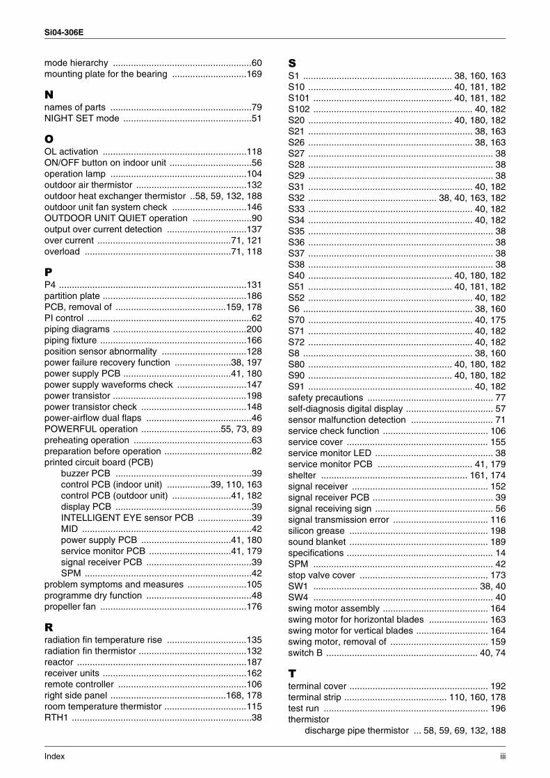
Si04-306E
mode hierarchy ......................................................60mounting plate for the bearing .............................169
Nnames of parts .......................................................79NIGHT SET mode ..................................................51
OOL activation ........................................................118ON/OFF button on indoor unit ................................56operation lamp .....................................................104outdoor air thermistor ...........................................132outdoor heat exchanger thermistor ..58, 59, 132, 188outdoor unit fan system check .............................146OUTDOOR UNIT QUIET operation .......................90output over current detection ...............................137over current ....................................................71, 121overload .........................................................71, 118
PP4 .........................................................................131partition plate ........................................................186PCB, removal of ...........................................159, 178PI control ................................................................62piping diagrams ....................................................200piping fixture .........................................................166position sensor abnormality .................................128power failure recovery function ......................38, 197power supply PCB ..........................................41, 180power supply waveforms check ...........................147power transistor ....................................................198power transistor check .........................................148power-airflow dual flaps .........................................46POWERFUL operation ...............................55, 73, 89preheating operation ..............................................63preparation before operation ..................................82printed circuit board (PCB)
buzzer PCB .....................................................39control PCB (indoor unit) .................39, 110, 163control PCB (outdoor unit) .......................41, 182display PCB .....................................................39INTELLIGENT EYE sensor PCB .....................39MID ..................................................................42power supply PCB ...................................41, 180service monitor PCB ................................41, 179signal receiver PCB .........................................39SPM .................................................................42
problem symptoms and measures .......................105programme dry function .........................................48propeller fan .........................................................176
Rradiation fin temperature rise ...............................135radiation fin thermistor ..........................................132reactor ..................................................................187receiver units ........................................................162remote controller ..................................................106right side panel .............................................168, 178room temperature thermistor ................................115RTH1 ......................................................................38
SS1 .......................................................... 38, 160, 163S10 ........................................................ 40, 181, 182S101 ...................................................... 40, 181, 182S102 .............................................................. 40, 182S20 ........................................................ 40, 180, 182S21 ................................................................ 38, 163S26 ................................................................ 38, 163S27 ........................................................................ 38S28 ........................................................................ 38S29 ........................................................................ 38S31 ................................................................ 40, 182S32 .................................................. 38, 40, 163, 182S33 ................................................................ 40, 182S34 ................................................................ 40, 182S35 ........................................................................ 38S36 ........................................................................ 38S37 ........................................................................ 38S38 ........................................................................ 38S40 ........................................................ 40, 180, 182S51 ........................................................ 40, 181, 182S52 ................................................................ 40, 182S6 .................................................................. 38, 160S70 ................................................................ 40, 175S71 ................................................................ 40, 182S72 ................................................................ 40, 182S8 .................................................................. 38, 160S80 ........................................................ 40, 180, 182S90 ........................................................ 40, 180, 182S91 ................................................................ 40, 182safety precautions ................................................. 77self-diagnosis digital display .................................. 57sensor malfunction detection ................................ 71service check function ......................................... 106service cover ....................................................... 155service monitor LED .............................................. 38service monitor PCB ..................................... 41, 179shelter ......................................................... 161, 174signal receiver ..................................................... 152signal receiver PCB ............................................... 39signal receiving sign .............................................. 56signal transmission error ..................................... 116silicon grease ...................................................... 198sound blanket ...................................................... 189specifications ......................................................... 14SPM ...................................................................... 42stop valve cover .................................................. 173SW1 ................................................................ 38, 40SW4 ...................................................................... 40swing motor assembly ......................................... 164swing motor for horizontal blades ....................... 163swing motor for vertical blades ............................ 164swing motor, removal of ...................................... 159switch B ........................................................... 40, 74
Tterminal cover ...................................................... 192terminal strip ........................................ 110, 160, 178test run ................................................................ 196thermistor
discharge pipe thermistor ... 58, 59, 69, 132, 188
Index iii
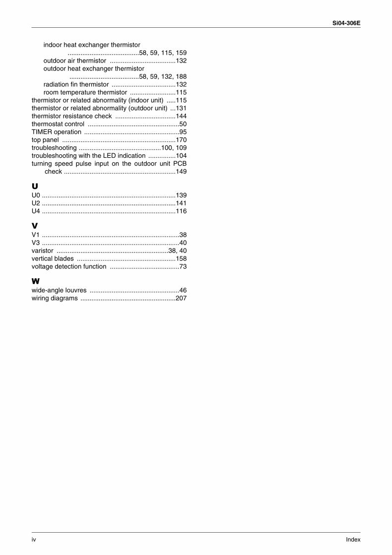
Si04-306E
indoor heat exchanger thermistor .......................................58, 59, 115, 159
outdoor air thermistor ....................................132outdoor heat exchanger thermistor
......................................58, 59, 132, 188radiation fin thermistor ...................................132room temperature thermistor .........................115
thermistor or related abnormality (indoor unit) .....115thermistor or related abnormality (outdoor unit) ...131thermistor resistance check .................................144thermostat control ..................................................50TIMER operation ....................................................95top panel ..............................................................170troubleshooting .............................................100, 109troubleshooting with the LED indication ...............104turning speed pulse input on the outdoor unit PCB
check .............................................................149
UU0 .........................................................................139U2 .........................................................................141U4 .........................................................................116
VV1 ...........................................................................38V3 ...........................................................................40varistor .............................................................38, 40vertical blades ......................................................158voltage detection function ......................................73
Wwide-angle louvres .................................................46wiring diagrams ....................................................207
iv Index
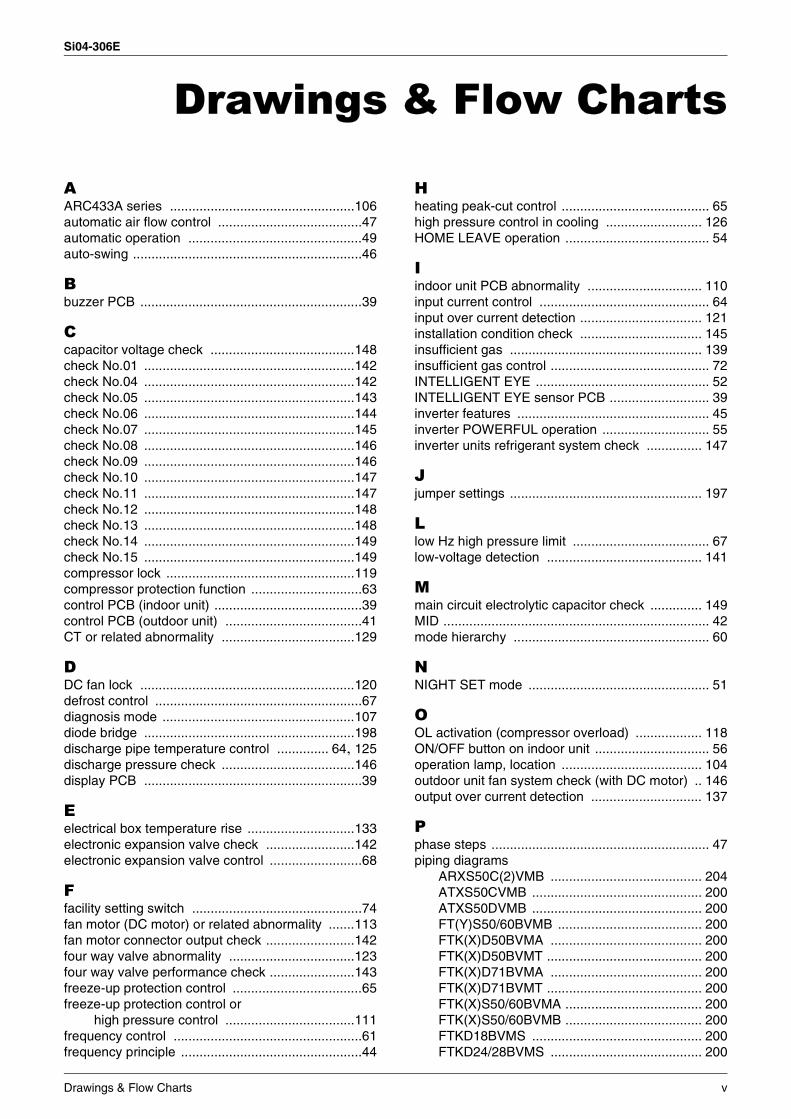
Si04-306E
Drawings & Flow Charts
AARC433A series ..................................................106automatic air flow control .......................................47automatic operation ...............................................49auto-swing ..............................................................46
Bbuzzer PCB ............................................................39
Ccapacitor voltage check .......................................148check No.01 .........................................................142check No.04 .........................................................142check No.05 .........................................................143check No.06 .........................................................144check No.07 .........................................................145check No.08 .........................................................146check No.09 .........................................................146check No.10 .........................................................147check No.11 .........................................................147check No.12 .........................................................148check No.13 .........................................................148check No.14 .........................................................149check No.15 .........................................................149compressor lock ...................................................119compressor protection function ..............................63control PCB (indoor unit) ........................................39control PCB (outdoor unit) .....................................41CT or related abnormality ....................................129
DDC fan lock ..........................................................120defrost control ........................................................67diagnosis mode ....................................................107diode bridge .........................................................198discharge pipe temperature control .............. 64, 125discharge pressure check ....................................146display PCB ...........................................................39
Eelectrical box temperature rise .............................133electronic expansion valve check ........................142electronic expansion valve control .........................68
Ffacility setting switch ..............................................74fan motor (DC motor) or related abnormality .......113fan motor connector output check ........................142four way valve abnormality ..................................123four way valve performance check .......................143freeze-up protection control ...................................65freeze-up protection control or
high pressure control ...................................111frequency control ...................................................61frequency principle .................................................44
Hheating peak-cut control ........................................ 65high pressure control in cooling .......................... 126HOME LEAVE operation ....................................... 54
Iindoor unit PCB abnormality ............................... 110input current control .............................................. 64input over current detection ................................. 121installation condition check ................................. 145insufficient gas .................................................... 139insufficient gas control ........................................... 72INTELLIGENT EYE ............................................... 52INTELLIGENT EYE sensor PCB ........................... 39inverter features .................................................... 45inverter POWERFUL operation ............................. 55inverter units refrigerant system check ............... 147
Jjumper settings .................................................... 197
Llow Hz high pressure limit ..................................... 67low-voltage detection .......................................... 141
Mmain circuit electrolytic capacitor check .............. 149MID ........................................................................ 42mode hierarchy ..................................................... 60
NNIGHT SET mode ................................................. 51
OOL activation (compressor overload) .................. 118ON/OFF button on indoor unit ............................... 56operation lamp, location ...................................... 104outdoor unit fan system check (with DC motor) .. 146output over current detection .............................. 137
Pphase steps ........................................................... 47piping diagrams
ARXS50C(2)VMB ......................................... 204ATXS50CVMB .............................................. 200ATXS50DVMB .............................................. 200FT(Y)S50/60BVMB ....................................... 200FTK(X)D50BVMA ......................................... 200FTK(X)D50BVMT .......................................... 200FTK(X)D71BVMA ......................................... 200FTK(X)D71BVMT .......................................... 200FTK(X)S50/60BVMA ..................................... 200FTK(X)S50/60BVMB ..................................... 200FTKD18BVMS .............................................. 200FTKD24/28BVMS ......................................... 200
Drawings & Flow Charts v
Si04-306E
FTKD50BVM .................................................200FTKD60BVM .................................................200FTKD60BVMA ...............................................200FTKD60BVMT ...............................................200FTKD71BVM .................................................200FTKS50BVMA8 .............................................200FTKS71BAVMB .............................................200FTKS71BVMA ...............................................200FTKS71BVMB ...............................................200FTXD50BV4 ..................................................200FTXD60BVMA ...............................................200FTXD60BVMT ...............................................200FTXD80CV4 ..................................................200FTXS71BAVMB .............................................200FTXS71BVMA ...............................................200FTXS71BVMB ...............................................200RKD18BVMS .................................................203RKD24/28BVMS ............................................203RKD50BVM ...................................................202RKD50BVMA .................................................202RKD50BVMT .................................................202RKD60BVM ...................................................203RKD60BVMA .................................................203RKD60BVMT .................................................203RKD71BVM ...................................................203RKD71BVMA .................................................203RKD71BVMT .................................................203RKS50B2VMB ...............................................201RKS50BVMA .................................................201RKS50BVMB(9) .............................................201RKS50BVMG .................................................201RKS60B2VMB ...............................................201RKS60BVMA .................................................201RKS60BVMB(9) .............................................201RKS71B2VMB ...............................................202RKS71B3VMB ...............................................202RKS71BVMA .................................................202RKS71BVMB(9) .............................................202RS50B(2)VMB ...............................................201RS60B(2)VMB ...............................................201RXD50BV4 ....................................................205RXD50BVMA .................................................205RXD50BVMT .................................................205RXD60BVMA .................................................206RXD60BVMT .................................................206RXD71BVMA .................................................206RXD71BVMT .................................................206RXD80CV4 ....................................................206RXS50B(2)VMB .............................................204RXS50BVMA .................................................204RXS60B(2)VMB .............................................204RXS60BVMA .................................................204RXS71B2VMB ...............................................205RXS71B3VMB ...............................................205RXS71BVMA .................................................205RXS71BVMB .................................................205RYS50B(2)VMB .............................................204RYS60B(2)VMB .............................................204
position sensor abnormality .................................128power supply PCB .................................................41power supply waveforms check ...........................147
power transistor ................................................... 198power transistor check ........................................ 148programme dry function ........................................ 48
Rradiation fin temperature rise .............................. 135remote controller ................................................. 106
Sservice monitor PCB ............................................. 41signal receiver PCB ............................................... 39signal transmission error
(between indoor and outdoor units) ............ 116silicon grease ...................................................... 198SPM ...................................................................... 42
Ttarget discharge pipe temperature control ............ 70thermistor
cooling only model .......................................... 59heat pump model ............................................ 58
thermistor or related abnormality (indoor unit) .... 115thermistor or related abnormality (outdoor unit) .. 131thermistor resistance check ................................ 144thermostat control ................................................. 50trial operation from remote controller .................. 196troubleshooting with the LED indication .............. 104turning speed pulse input on the outdoor unit PCB
check ............................................................ 149
Wwiring diagrams
ARXS50C(2)VMB ......................................... 210ATXS50CVMB .............................................. 207ATXS50DVMB .............................................. 207FT(Y)S50BVMB ............................................ 208FT(Y)S60BVMB ............................................ 208FTK(X)D50/60/71BVMA ............................... 207FTK(X)D50/60/71BVMT ................................ 207FTK(X)S50BVMB .......................................... 207FTK(X)S60/71BVMA ..................................... 207FTK(X)S60/71BVMB ..................................... 207FTK(X)S71BAVMB ....................................... 207FTKD18/24/28BVMS .................................... 209FTKD50/60/71BVM ....................................... 207FTKS50BVMA(8) .......................................... 207FTXD50BV4 .................................................. 207FTXD80CV4 ................................................. 207FTXS50BVMA .............................................. 207RKD18/24/28BVMS ...................................... 211RKD50/60/71BVM ........................................ 210RKD50/60/71BVMA ...................................... 210RKD50/60/71BVMT ...................................... 210RKS50/60/71B2VMB .................................... 210RKS50/60/71BVMA ...................................... 210RKS50/60/71BVMB(9) .................................. 210RKS50BVMG ................................................ 210RKS71B3VMB .............................................. 210RS50/60B(2)VMB ......................................... 210RXD50/60/71BVMA ...................................... 210RXD50/60/71BVMT ...................................... 210
vi Drawings & Flow Charts
Si04-306E
RXD50BV4 ....................................................210RXD80CV4 ....................................................210RXS50/60/71B(2)VMB ...................................210RXS50/60/71BVMA .......................................210RXS71B3VMB ...............................................210RYS50/60B(2)VMB ........................................210
Drawings & Flow Charts vii
Si04-306E
viii Drawings & Flow Charts
Specifications, designs and other content appearing in this brochure are current as of May 2008 but subject to change without notice.Si 04-306EPrinted in Japan 05/2008 B AK
![Service Manual - splitsystema48.rusplitsystema48.ru/images/doc/Daikin/SiBE06-708_C_FVXS-F_tcm135... · SiBE06-708_C [Applied Models] O Inverter Pair : ... 4.2 Indoor Unit PCB Abnormality](https://img.pdfslide.net/doc/110x75/5aeb1d117f8b9ae5318d5147/service-manual-applied-models-o-inverter-pair-42-indoor-unit-pcb-abnormality.jpg)

![Service Manual - Innovative Air Conditioning Solutions. Daikin/4. Emura/Emura - Wall... · Service Manual [Applied Models] z Inverter Pair : ... 4.20 Position Sensor Abnormality](https://img.pdfslide.net/doc/110x75/5ace193b7f8b9a6a678e4896/service-manual-innovative-air-conditioning-daikin4-emuraemura-wallservice.jpg)