Embed Size (px)
Citation preview

INVERTERS: The Investigation to the
Presenter: Dr Gawie van der Merwe
static as well as mobile applicationssinewave inverter range for the use inoptimal topology to the designing of a

Copyright: Dr Gawie van der Merwe www.planmypower.co.za
Background
Investigation towards:– Efficiency– Cost– Reliability– Manufacture (Complexity/Simplicity)
Investigations done in order to search for the optimal topology.
Various Topologies exist.
PV and Mobile Inverters with a sinewave output is the optimal requirement.

Copyright: Dr Gawie van der Merwe www.planmypower.co.za
Sinewave Inverter Topologies
CVT (Constant Voltage Transformer)50Hz Transformer
– Push Pull Primary- – Full Bridge switching in Primary with series
line Inductor
High Frequency Isolation Transformer and Secondary H-Bridge Control
Series or Parallel Transformer switching

Copyright: Dr Gawie van der Merwe www.planmypower.co.za
A) Constant Voltage Transformer
SINEWAVE OUTPUT
BATTERY
CVT
Transformer
Inverter “push-pull”
Resonantcomponents
(Ferro Resonant Transformer)

Copyright: Dr Gawie van der Merwe www.planmypower.co.za
B) 50Hz - Transformer Topology
Various “50Hz” transformer topologies exist
3 Full Bridge Inductor in primary
1 Push-pull - Inductor in primary
2 Push-pull - Inductor in secondary

Copyright: Dr Gawie van der Merwe www.planmypower.co.za
-10 0 10 20 30
-400
-200
0
200
400
-3
-2
-1
0
1
2
3
TIME (5MS/DIV)
VO
LTA
GE (
V)
CU
RR
EN
T (
A)
CURRENT
VOLTAGE
VOLTAGE AND CURRENTLINEAR LOAD
50Hz TRANSFORMER
-10 0 10 20 30
-400
-200
0
200
400
-8
-6
-4
-2
0
2
4
6
8
TIME (5MS/DIV)
VO
LTA
GE (
V)
CU
RR
EN
T (
A)
CURRENT
VOLTAGE
VOLTAGE AND CURRENTNON-LINEAR LOAD
50Hz TRANSFORMER

Copyright: Dr Gawie van der Merwe www.planmypower.co.za
Topology B1
SINEWAVE OUTPUT
BATTERY
INDUCTOR
SINE-REF
FEEDBACK
ERROR AMP
SAWTOOTH
DRIVE CIRCUITAND CONTROLLATCH
TOROID
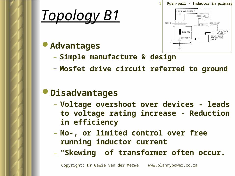
1 Push-pull - Inductor in primary
Copyright: Dr Gawie van der Merwe www.planmypower.co.za
Topology B1
Disadvantages– Voltage overshoot over devices - leads to
voltage rating increase - Reduction in efficiency
– No-, or limited control over free running inductor current
– “Skewing” of transformer often occur.
Advantages– Simple manufacture & design
– Mosfet drive circuit referred to ground
SINEWAVE OUTPUT
BATTERY
INDUCTOR
SINE-REF
FEEDBACK
ERROR AMP
SAWTOOTH
DRIVE CIRCUITAND CONTROLLATCH
TOROID
1 Push-pull - Inductor in primary

Copyright: Dr Gawie van der Merwe www.planmypower.co.za
Primary side Push-pull, series inductor in secondary
SINEWAVE OUTPUT
BATTERY
SINE-REF
FEEDBACK
ERROR AMP
SAWTOOTH
DRIVE CIRCUITAND CONTROLLATCH
TOROID
INDUCTOR
Topology B22 Push-pull - Inductor in secondary

Copyright: Dr Gawie van der Merwe www.planmypower.co.za
Topology B2
Advantages– Simple manufacture & design
– Mosfet drive circuit referred to ground
Disadvantages– Voltage overshoot over devices - leads to
voltage rating increase - Reduction in efficiency
– No-, or limited control over free running inductor current
– “Skewing” of transformer often occur.
SINEWAVE OUTPUT
BATTERY
SINE-REF
FEEDBACK
ERROR AMP
SAWTOOTH
DRIVE CIRCUITAND CONTROLLATCH
TOROID
INDUCTOR
2 Push-pull - Inductor in secondary

Copyright: Dr Gawie van der Merwe www.planmypower.co.zaMost popular used topology
SINEWAVE OUTPUT
SINE-REF
FEEDBACK
ERROR AMP
SAWTOOTH
DRIVE CIRCUITAND CONTROLLATCH
TOROID
INDUCTOR
BATTERY
Topology B33 Full Bridge Inductor in primary

Copyright: Dr Gawie van der Merwe www.planmypower.co.za
Advantages– Complete control over primary side inductor
current– Uni-as well as bi-polar pwm control strategy
possible– Simple manufacturing
Topology B3
Disadvantages– System design is more complex– Inverter efficiency is load dependent
SINEWAVE OUTPUT
SINE-REF
FEEDBACK
ERROR AMP
SAWTOOTH
DRIVE CIRCUITAND CONTROLLATCH
TOROID
INDUCTOR
BATTERY
3 Full Bridge Inductor in primary

Copyright: Dr Gawie van der Merwe www.planmypower.co.za
C) High Frequency Isolation
SAWTOOTH
TOROID
INDUCTOR
BATTERY
SINEWAVE OUTPUT
ERROR AMP
SINE-REF
FEEDBACKDRIVE CIRCUITAND CONTROLLATCH
PRIMARY SIDE DEVICESCONTROLLED TO OFFERA FIXED DC LINK VOLTAGE

Copyright: Dr Gawie van der Merwe www.planmypower.co.za
High frequency isolation reduce physical size– Direct output control leads to better
output waveform control and reduced distortion
C) High Frequency Isolation Transformer with full H-bridge Control on Secondary

Copyright: Dr Gawie van der Merwe www.planmypower.co.za
-10 0 10 20 30-400
-200
0
200
400
-4
-2
0
2
4
TIME (5MS/DIV)
VO
LTA
GE (
V)
CU
RR
EN
T (
A)
CURRENT
VOLTAGE
VOLTAGE AND CURRENTLINEAR LOAD
HIGH FREQUENCY INVERTER
-10 0 10 20 30-400
-200
0
200
400
-6
-4
-2
0
2
4
6
TIME (5MS/DIV)
VO
LTA
GE (
V)
CU
RR
EN
T (
A)
CURRENT
VOLTAGE
VOLTAGE AND CURRENTNON-LINEAR LOAD
HIGH FREQUENCY INVERTER

Copyright: Dr Gawie van der Merwe www.planmypower.co.za
Advantages– Units generally more mobile– Possible to limit battery current drawn to a
“smooth DC”– Good efficiency with a non linear load
High Frequency Isolation Transformer
Disadvantages– Design is complex– Manufacture is complex– High cost

Copyright: Dr Gawie van der Merwe www.planmypower.co.za
A wide range of topologies exist
D) Transformer - series and/or parallel switching
A combination of various Transformer switching topologies
– Transformer secondary is in series– Separate output voltage & frequency for
each transformer

Copyright: Dr Gawie van der Merwe www.planmypower.co.za
BATTERY
(B)(A) (C)
(A+B+C) =
SINEWAVEOUTPUT
Transformer-series and/or parallel switching

Copyright: Dr Gawie van der Merwe www.planmypower.co.za
-10 0 10 20 30-400
-200
0
200
400
TIME (5MS/DIV)
VO
LTA
GE (
V)
VOLTAGE
VOLTAGE OUTPUT OF MULTI TRANSFORMERINVERTER
MATRIX TRANSFORMER INVERTER
-10 0 10 20 30-400
-200
0
200
400
TIME (5MS/DIV)
VO
LTA
GE (
V)
VOLTAGE
ZOOM INTO VOLTAGE STEPS
MATRIX INVERTER

Copyright: Dr Gawie van der Merwe www.planmypower.co.za
Advantages– High running to overload ratio is – Very popular design– Advantages for motor startup– High efficiency
Transformer -series and/or parallel switching
Disadvantages– Control complex– Manufacturing is complex– Inverter is big and bulky

Copyright: Dr Gawie van der Merwe www.planmypower.co.za
Summary
Different topologies have advantages for different applications
Both topology A, B1&B2, (50Hz topology) are outdated
High frequency option, has mobility & weight advantage– Output distortion under all conditions low
Matrix transformer topology– Physical dimensions restrains mobility– Ideal for short period overload power
peak/Mass ratio is good

Copyright: Dr Gawie van der Merwe www.planmypower.co.za
Estimated Inverter Manufacturing Costs (Same Input Power Stage)
0
1
2
3
4
Th
ou
sa
nd
s
VA
Cost (per u
nit)
300 500 750 1000 1500 3000 5000
QS-INV
HF-SINE
MATRIX SINE
INVERTER MANUFACTURING COST(Based on Linear load)
Input power stage same for comparing Calculation done on continues rating without forced air
cooling Cost calculated on discreet units

Copyright: Dr Gawie van der Merwe www.planmypower.co.za
Non linear load as a % of total power consumption
Non linear loads - high percentage on power application below 1Kva typical loads, computer, fluorescent lights, video
Higher power application, more resistive, i.e. Microwave, Hairdryer etc. < 1Kva most sensitive to PV applications
0
20
40
60
80
100
POWER INVERTER
LO
AD
PR
OB
AB
ILIT
Y
100 1000 2000 3000
NON-LINEARLOAD LINEAR LOADS
NON LINEAR LOAD AS % OF FULL POWER(TYPICAL APPLICATIONS)

Copyright: Dr Gawie van der Merwe www.planmypower.co.za
0
2
4
6
8
POWER
SY
STEM
EFFIC
IEN
CY
LO
SS
ES
%
100.00 1000.00 2000.00 3000.00
HF TOPOLOGY
50HZ TOPOLOGY
WEIGHTED % SYSTEM LOSSES AS RESULT OF NON-LINEAR LOAD
(LOSSES DUE TO INVERTER CHOICE)
0 1 2 3 40
5
10
15
20
Thousands
POWER INVERTER (WATT)
EFFIC
IEN
Y L
OS
S (
%)
HF TOPOLOGY
50HZ TOPOLOGY
INVERTER EFFICIENCY LOSS DUE TO NON-LINEAR LOAD
ASSUMPTION 100% LOADSAME POWER STAGE DESIGN

Copyright: Dr Gawie van der Merwe www.planmypower.co.za
Topology Suggestionsfor Power Levels
Power RatingHigh
FrequencyFull Bridge
50HzMatrix Config.
100-600WMobile (most cost efficient)
50%
Advantage onperm installation
60%
Too expensive
10%
400W-1500WMobile General
70%PV-Permanent
100%PV-Permanent
40%
1000W-2,5Kw PV-Permanent 70%
PV & MobileStackable units
in parallel 70%
PV Permanent
Best choice 80%
2Kw-5Kw
Stackable parallel
combination 100%
Stackable Units
80%Mobile
30%
(Percentage indicates topology choice for the application)