Embed Size (px)
Citation preview

by
Reliability,
Security,
User Friendly.
Lab
eL
FAIL SAFE ELECTRIC ACTUATORS
FQ RAngE
Invest in ConfidenceInvest in Confidence
Bernard Controls sa4 rue d’arsonval - B.P. 70091
95505 Gonesse CedeX Francetel. : +33 (0)1 34 07 71 00Fax : +33 (0)1 34 07 71 [email protected]
All
data
in t
his
bro
chu
re a
re g
iven
for
info
rmat
ion
on
ly a
nd
are
subj
ect
to c
han
ge w
ith
out
not
ice.
SUBSIDIARIES
BELGIUMBERNARD CONTROLS BENELUXBrUXelles
[email protected] +32 (0)2 343 41 22
CHINABERNARD CONTROLS CHINAPeKIn
[email protected] +86 (0) 10 6789 2861
GERMANYBERNARD CONTROLS DEUFRAtroIsdorF
[email protected] +49 22 41 98 340
ITALIABERNARD CONTROLS ITALIAMIlan
[email protected] +39 02 931 85 233
KOREA (REPUBLIC OF)BERNARD CONTROLS KOREAseoUl
[email protected] +82 02-2270-3880
SINGAPOREBERNARD CONTROLS SINGAPOREsInGaPore
[email protected] +65 65654227
SPAINBERNARD CONTROLS SPAINMadrId
[email protected] +34 91 30 41 139
UNITED STATESBERNARD CONTROLS IncHoUston
[email protected] +1 281 578 66 66
OFFICES
BanGKoKBERNARD CONTROLSSOUTH-EAST [email protected] +66 2 640 82 64
dUBaÏ BERNARD [email protected] +971 4 344 2010
MosCoWBERNARD [email protected] +(7 499) 251 06 54 or +(7 916) 911 28 42
AGENTS AND DISTRIBUTORS
AMERICAS
Information on our networkwww. bernardcontrols.com orBack officeBernard Controls [email protected] +1 281 578 66 66
BRAZILJCNsao [email protected] +55 11 39 02 26 00
ASIA
Information on our networkwww. bernardcontrols.com
orTo contact our distributorsBack officeBernard Controls [email protected] +86 10 6789 2861
EUROPE - MIDDLE EAST - AFRICA
Information on our networkwww.bernardcontrols.com orBack Office Bernard Controls [email protected] +33 (0)1 34 07 71 00
orContact directly agents/distributors
AUSTRIAIPU ING PAUL [email protected] +43 1 602 41 49
CZECH REPUBLICFLUIDTECHNIK BOHEMIA [email protected] +420 548 213 233-5
DENMARKARMATEC A/[email protected] + 45 46 96 00 00
[email protected] +203 582 76 47
FINLANDTALLBERG TECH OY [email protected] +358 0 207 420 740
GREECEPI&MS Entreprises [email protected] +30 210 608 61 52
HUNGARYAPAGYI TRADEIMPEX [email protected] +36 1 223 1958
MOROCCOAQUATEL [email protected] +212 22 66 55 71
[email protected] +48 33 81 84004
[email protected] +48 22 864 55 43
SOUTH AFRICAA-Q-RATE AUTOMATION [email protected] +27 11 432 58 31
SWITZERLANDMATOKEM [email protected] +41 61 483 15 40
[email protected] +90 216 326 39 39
UNITED KINGDOMZOEDALE [email protected] +44 12 34 83 28 28
Exhaustive list of agents and distributors on www.bernardcontrols.com
a10
5/0
4
All
data
in t
his
bro
chu
re a
re g
iven
for
info
rmat
ion
on
ly a
nd
are
subj
ect
to c
han
ge w
ith
out
not
ice.

ReliabilitySecurityUser Friendly
Lab
eL
BERNARD CONTROLS introduces the BC Premium label.The BC Premium label is the guarantee of high performance, reliable and innovative actuator solutions designed to sustain severe environmental and operational conditions.Decades of return of experience from very demanding applications such as nuclear qualified valves actuation have shaped our technical orientations and our commitment to quality and safety.Moreover, BC Premium labeled products offer user-friendliness and extremely low level of maintenance requirements.
Contents
Fail safe electric actuators > 4
Main features > 6
Technical data > 8
Performances > 12
Dimensional drawings > 16
Standard mounting > 18
Wiring diagram > 19

Failsafe electric actuatorsFor all quarter-turn applications, spring return FQ range actuators ensure
automatic opening or closing even without any power supply.
When energized, the actuator operates the valve normally and at the same
time compresses the spring which is held in the loaded position by a solenoid
brake.
In case of power failure to the solenoid, the spring will drive the actuator and
valve to the safety position either open or closed. The associated dashpot
speed controls the spring action and allows a safe and shockfree operation of
the valve.
When the power supply is restored (no resetting of the spring is required), the
actuator is immediately available for normal operation.
In standard, the spring operates clockwise when viewed from the top. The
electric part is equipped with an asynchronous three-phase motor of squirrel
cage type. Other versions are available in single phase and direct current
supply.
All applications where the loss of power supply requires automatically to put
the driven device in a safety position.
All applications where the risks are such, that driving the device to its safety
position must be possible at any time even in the absence of power supply.
Operating principle
Application fields
Storage and distribution of gas and dangerous fluids
Refineries trucks loading arms
Fire protection systems
Chemical installation safety
Climate control and ventilation on hazardous areas
Tunnel ventilation
For example :
4 FQ Range 5
Lab
eL
Lab
eL

What is Fail Safe ?
The activation of an emergency signal triggers the immediate opening or closing of the backup device, without the need of any external power source and using a full mechanical spring return.
This signal can be activated following:• An abnormal event (fire, overflow ...)• An automatic control• An operator’s action• A lack of power supply
Main featuresFor all quarter turn applications, spring return FQ range actuators ensure
automatic opening or closing even without any power supply.
• No periodic maintenance required.
• Trouble free operation for years (the FQ system is not battery technology based).
• Spring efficiency guaranteed over the full 90° travel.
• Fast and shock-free operation of the valve during emergency closing / opening.
• Travel limit switches easy to set with a simple screw driver and unaffected by
mechanical vibrations effects.
• Easy access to electrical connections via a terminal strip.
FQ actuator is supplied complete with:
• Mechanical position indicator
• Adjustable quarter-turn mechanical stops
• 2 travel limit switches setting easy, with a simple screw driver
• Electrical connection to a terminal strip
• Emergency handwheel on all models (excepted the FQ04 and the FQ08)
FQ actuators are available as:
• On-Off: Maximum recommended 20-30 full stroke travels per day. 30% motor
service duty.
• Class III: Modulating intermediate positioning with a precision better than 2%.
Maximum recommended: 360 movements per day. 50% motor service duty.
Easy to use, maintenance free
EnclosuresFQ actuators are weather-proof to IP67 and are also available as
explosion-proof according to international standards.
• Motor:
3PH 50 or 60 Hz
1PH 50 or 60 Hz
DC versions
• On/Off or Positioning
• Advanced controls with local buttons
INTEGRAL+ (On/Off)
POSIGAM+ (Positioning)
• Extra limit switches
• Anticondensation heater resistor
• Position transmitters : 4-20mA or potentiometer
• Solenoid brake
115V AC
230V AC
DC version
• Fast spring return
• Clockwise or counterclockwise spring action
Possible options
6 FQ Range 7
Lab
eL
Lab
eL

Torque range Quarter-turn, direct mounting from 40 to 500Nm
Modulating class On-off or class III
Enclosure Cast aluminium
Waterproofness IP67
Programming FQ range is generally proposed with standard control (camblock + end-of-travel switches).INTEGRAL+ & POSIGAM+ (See INTEGRAL+ catalogue) advanced controls are also possible with separated control box. Maximum distance between control box and actuator: 50m
Explosion proof ATEX(option)
ATEX Directive 94/9/EC - CENELEC EN 50014, EN 50018As standard: EEx d IIC T4 (option T5 or T6) - Ex II 2 GCertificate : LCIE 02 ATEX 6902
Ambient temperature operating range
EEx d IIC T4 : -20°C to 70°C (-40°C in option)EEx d IIC T5 : -20°C to 65°C (-40°C in option)EEx d IIC T6 : -20°C to 50°C (-40°C in option)
Explosion proof C.S.A. (Canada & USA)(option)
NEMA 7 - NEMA 9 certifiedC22-2, FM3600, FM3611 and FM3615 standardsClass I Group C, D div 1&2 (option Group B)Class II Group E, F, G div 1&2Certificate : 1061444
External corrosion protection Standard paint system: Zinc rich primer, epoxy undercoat and RAL5002 blue protection polyurethane top coat.Optional special anti-corrosion protection for marine, aggressive or abrasive atmospheres.All cover fasteners captive and stainless.
Motor technology TENV type (Totally Enclosed Non Ventilated).Class F insulation class.Integrated thermal overload protection.
Motor duty rating S4 motor service (Intermittent periodic duty with startings) to IEC 34-1• S4 - 30% for ON/OFF operation - up to 360 starts per hour.• S4 - 50% for Modulating class III - up to 1,200 starts per hour.
Gearing Self-locking
Manual override Function available on FQ12, FQ18, FQ30 and FQ50.Handwheel does not rotate during motor operation.Padlockable clutch lever.
Spring return CW as standard, CCW on request (non reversible device)Fast spring return in option
Output flange Flange comply with ISO 5211 (Optionnal standard flange on FQ04 to FQ18).
Output drive Direct output drive on FQ04 to FQ18 (Removable socket in option).Removable socket on FQ30 and FQ50.
Vibration Resistance 1g (9.8 m/s²) at 10-500 HzFor higher vibration resistance, please contact us.
Lubrication Actuators are lubricated for product lifetime and do not require any specific periodic maintenance
Mec
hani
cal s
peci
ficat
ions
Mot
oren
clos
ure
Gen
eral
sp
ecifi
cati
ons
Technical data general specifications
elec
tric
al s
peci
ficat
ions
Power supply Actuators are available for a wide range of power supplies:• Single-phase, three-phase or DC voltages• 50 ou 60 Hz• Specific voltages on request
Cable entries Standard configuration (other on request): 2xM20 • 1 for signalling, • 1 for power supply
Solenoid brake The solenoid rated power is 21 W. This solenoid is normally under permanent power supply.Need separated power supply. Nominal voltage:• 230V AC for 230V or 400V AC actuators• 115V AC for 115V or 460V AC actuators• 24V DC for 24V DC actuatorsOther possible voltages on request
Position sensors • Movement read directly on the main shaft (direct mechanical link)• Adjustable camblock with 2 SPDT end-of-travel switches• 2 extra position switches in option• Independent position transmitter (TAM or potentiometer) in option
8 FQ Range 9
Lab
eL

Models Two versions according to operating modes:INTEGRAL+ for ON/OFF which includes :• Terminal compartment • Power contactors • Logic control • Configuration panel• Signalling relays• Local control selectorsPOSIGAM+ for Class III positioning :• All INTEGRAL+ features• Positioner board• Position feedback
Enclosure protection Separated FPi box (weatherproof design)• Standard: IP67 / NEMA 4Separated FPx box (explosionproof design)• Standard: IP67 / EEx d IIC T6 - NEMA 7 / 9
On-off control • Isolated by opto-couplers• Voltage: 10 to 250 V DC/AC• Current: 10 mA at 24V• Dry contacts (uses INTEGRAL+ auxiliary DC supply)• Minimum pulse duration: 100ms• Time of rotational direction change: 50ms or 200ms
Positioning control • Standard : Input signal 4-20 mA - Output signal 4-20 mA• On request :Input signal 0-20 mA - Output signal 0-20 mA• On request : Input signal 0-10 V - Output signal 0-20 mA
Signaling relays • 4 relays: 4 datas can be freely selected among a total of 16 available datas (250VAC-5A max.)• 1 fault relay
Cable entries Standard configuration (other on request): 3xM20 (2 for signalling, 1 for power supply)
EU conformity INTEGRAL+ / POSIGAM+ controls complying with:• The 2004/108/EC electromagnetic compatibility• The 2006/95/EC low voltage• The following harmonized standards: Generic emission standard-Industrial environment EN 61000-6-4Generic immunity standard - Industrial environment EN 61000-6-2.Degrees of protection provided by enclosures (IP code) EN 60529
Vibration resistance 1g (9.8 m/s²) at 10-500 Hz
Fieldbus interface(option)
Profibus DP (single or redundant)• PROFIBUS-DP slave - RS 485• Baudrate: autodetection• Total number of master and slave modules on the same line: 31 max. up to 99 with repeaters• PROFIBUS operability approved by PNO (Profibus Nutzer Organisation)• External power supply backup
Additional options • LED indication board (closed, open, power on)• Additional 3 relays board• Additional position transmitter isolated from the other output signals
adv
ance
d co
ntro
ls(o
ptio
n)ad
dItI
onal
oPt
Ions
10 FQ Range 11
Lab
eL
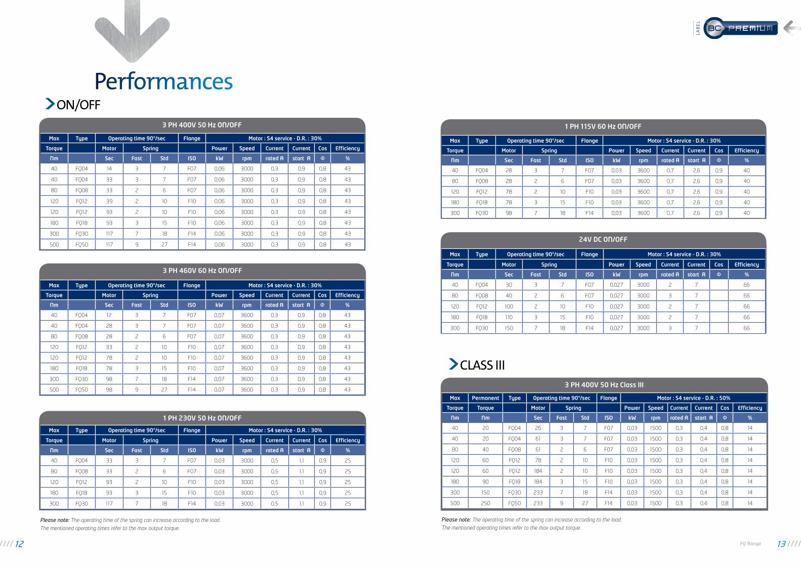
1 PH 115V 60 Hz ON/OFF
24V DC ON/OFF
Max Type Operating time 90°/sec Flange Motor : S4 service - D.R. : 30%
Torque Motor Spring Power Speed Current Current Cos Efficiency
Nm Sec Fast Std ISO kW rpm rated A start A Ф %
40 FQ04 28 3 7 F07 0,03 3600 0,7 2,6 0,9 40
80 FQ08 28 2 6 F07 0,03 3600 0,7 2,6 0,9 40
120 FQ12 78 2 10 F10 0,03 3600 0,7 2,6 0,9 40
180 FQ18 78 3 15 F10 0,03 3600 0,7 2,6 0,9 40
300 FQ30 98 7 18 F14 0,03 3600 0,7 2,6 0,9 40
Max Type Operating time 90°/sec Flange Motor : S4 service - D.R. : 30%
Torque Motor Spring Power Speed Current Current Cos Efficiency
Nm Sec Fast Std ISO kW rpm rated A start A Ф %
40 FQ04 30 3 7 F07 0,027 3000 2 7 66
80 FQ08 40 2 6 F07 0,027 3000 3 7 66
120 FQ12 100 2 10 F10 0,027 3000 2 7 66
180 FQ18 110 3 15 F10 0,027 3000 2 7 66
300 FQ30 150 7 18 F14 0,027 3000 3 7 66
On/OFF
1 PH 230V 50 Hz ON/OFF
3 PH 460V 60 Hz ON/OFF
3 PH 400V 50 Hz ON/OFF
Max Type Operating time 90°/sec Flange Motor : S4 service - D.R. : 30%
Torque Motor Spring Power Speed Current Current Cos Efficiency
Nm Sec Fast Std ISO kW rpm rated A start A Ф %
40 FQ04 14 3 7 F07 0,06 3000 0,3 0,9 0,8 43
40 FQ04 33 3 7 F07 0,06 3000 0,3 0,9 0,8 43
80 FQ08 33 2 6 F07 0,06 3000 0,3 0,9 0,8 43
120 FQ12 39 2 10 F10 0,06 3000 0,3 0,9 0,8 43
120 FQ12 93 2 10 F10 0,06 3000 0,3 0,9 0,8 43
180 FQ18 93 3 15 F10 0,06 3000 0,3 0,9 0,8 43
300 FQ30 117 7 18 F14 0,06 3000 0,3 0,9 0,8 43
500 FQ50 117 9 27 F14 0,06 3000 0,3 0,9 0,8 43
Max Type Operating time 90°/sec Flange Motor : S4 service - D.R. : 30%
Torque Motor Spring Power Speed Current Current Cos Efficiency
Nm Sec Fast Std ISO kW rpm rated A start A Ф %
40 FQ04 12 3 7 F07 0,07 3600 0,3 0,9 0,8 43
40 FQ04 28 3 7 F07 0,07 3600 0,3 0,9 0,8 43
80 FQ08 28 2 6 F07 0,07 3600 0,3 0,9 0,8 43
120 FQ12 33 2 10 F10 0,07 3600 0,3 0,9 0,8 43
120 FQ12 78 2 10 F10 0,07 3600 0,3 0,9 0,8 43
180 FQ18 78 3 15 F10 0,07 3600 0,3 0,9 0,8 43
300 FQ30 98 7 18 F14 0,07 3600 0,3 0,9 0,8 43
500 FQ50 98 9 27 F14 0,07 3600 0,3 0,9 0,8 43
Max Type Operating time 90°/sec Flange Motor : S4 service - D.R. : 30%
Torque Motor Spring Power Speed Current Current Cos Efficiency
Nm Sec Fast Std ISO kW rpm rated A start A Ф %
40 FQ04 33 3 7 F07 0,03 3000 0,5 1,1 0,9 25
80 FQ08 33 2 6 F07 0,03 3000 0,5 1,1 0,9 25
120 FQ12 93 2 10 F10 0,03 3000 0,5 1,1 0,9 25
180 FQ18 93 3 15 F10 0,03 3000 0,5 1,1 0,9 25
300 FQ30 117 7 18 F14 0,03 3000 0,5 1,1 0,9 25
Please note: The operating time of the spring can increase according to the load.
The mentioned operating times refer to the max output torque.
Performances
3 PH 400V 50 Hz Class III
Max Permanent Type Operating time 90°/sec Flange Motor : S4 service - D.R. : 50%
Torque Torque Motor Spring Power Speed Current Current Cos Efficiency
Nm Nm Sec Fast Std ISO kW rpm rated A start A Ф %
40 20 FQ04 26 3 7 F07 0,03 1500 0,3 0,4 0,8 14
40 20 FQ04 61 3 7 F07 0,03 1500 0,3 0,4 0,8 14
80 40 FQ08 61 2 6 F07 0,03 1500 0,3 0,4 0,8 14
120 60 FQ12 78 2 10 F10 0,03 1500 0,3 0,4 0,8 14
120 60 FQ12 184 2 10 F10 0,03 1500 0,3 0,4 0,8 14
180 90 FQ18 184 3 15 F10 0,03 1500 0,3 0,4 0,8 14
300 150 FQ30 233 7 18 F14 0,03 1500 0,3 0,4 0,8 14
500 250 FQ50 233 9 27 F14 0,03 1500 0,3 0,4 0,8 14
Please note: The operating time of the spring can increase according to the load.
The mentioned operating times refer to the max output torque.
CLASS III
12 FQ Range 13
Lab
eL

3 PH 460V 60 Hz Class III
1 PH 230V 50 Hz Class III
1 PH 115V 60 Hz Class III
Max Permanent Type Operating time 90°/sec Flange Motor : S4 service - D.R. : 50%
Torque Torque Motor Spring Power Speed Current Current Cos Efficiency
Nm Nm Sec Fast Std ISO kW rpm rated A start A Ф %
40 20 FQ04 22 3 7 F07 0,04 1800 0,3 0,4 0,9 14
40 20 FQ04 51 3 7 F07 0,04 1800 0,3 0,4 0,9 14
80 40 FQ08 51 2 6 F07 0,04 1800 0,3 0,4 0,9 14
120 60 FQ12 65 2 10 F10 0,04 1800 0,3 0,4 0,9 14
120 60 FQ12 154 2 10 F10 0,04 1800 0,3 0,4 0,9 14
180 90 FQ18 154 3 15 F10 0,04 1800 0,3 0,4 0,9 14
300 150 FQ30 194 7 18 F14 0,04 1800 0,3 0,4 0,9 14
500 250 FQ50 194 9 27 F14 0,04 1800 0,3 0,4 0,9 14
Max Permanent Type Operating time 90°/sec Flange Motor : S4 service - D.R. : 50%
Torque Torque Motor Spring Power Speed Current Current Cos Efficiency
Nm Nm Sec Fast Std ISO kW rpm rated A start A Ф %
40 20 FQ04 66 3 7 F07 0,02 1500 0,5 0,7 0,9 13
80 40 FQ08 66 2 6 F07 0,02 1500 0,5 0,7 0,9 13
120 60 FQ12 184 2 10 F10 0,02 1500 0,5 0,7 0,9 13
180 90 FQ18 184 3 15 F10 0,02 1500 0,5 0,7 0,9 13
300 150 FQ30 233 7 18 F14 0,02 1500 0,5 0,7 0,9 13
Max Permanent Type Operating time 90°/sec Flange Motor : S4 service - D.R. : 50%
Torque Torque Motor Spring Power Speed Current Current Cos Efficiency
Nm Nm Sec Fast Std ISO kW rpm rated A start A Ф %
40 20 FQ04 55 3 7 F07 0,03 1800 1 1,2 0,9 20
80 40 FQ08 55 2 6 F07 0,03 1800 1 1,2 0,9 20
120 60 FQ12 154 2 10 F10 0,03 1800 1 1,2 0,9 20
180 90 FQ18 154 3 15 F10 0,03 1800 1 1,2 0,9 20
300 150 FQ30 194 7 18 F14 0,03 1800 1 1,2 0,9 20
Please note: The operating time of the spring can increase according to the load.
The mentioned operating times refer to the max output torque.
CLASS III
14 FQ Range 15
Lab
eL

Type A Ø B Square C h Weight
FQ04 386 Ø 84 17 19 25 kgFQ08 396 Ø 117 22 24 30 kg
Type A B Ø C D Square E Ø F M Weight
FQ12 500 167 Ø 117 25 22 Ø 102 M10 40 kgFQ18 518 185 Ø 130 31 25 Ø 78 M12 45 kg
FQ04 & FQ08
FQ12 & FQ18
Dimensional drawings
Square C2 x 45°
Depth h
Connection
Stop screws90° +/- 2°
"Closed" position
Positionindicator
B
Ø CD
A
Ø F
Connection
"Closed" position
4 x
M d
epth
: 20
Stop
scr
ews
90°
+/- 2
°
lockagehandwheelclutch
Positionindicator Square E
M
Square E
FQ30
FQ50
Ø290
793
451
101
90°0°
2
A
474
Ø10
0 f8
Ø14
0Ø
175
Position indicator
"Op
en" p
osit
ion
4 x
M16
dep
th 2
5 =
F14
lockablehandwheelclutch
Connection
Weight100 kg
Ø290
Ø394
410
753
90° 0°
101
2
A 474
Ø10
0 f8
Ø14
0Ø
175
"Op
en" p
osit
ion
4 x
M16
dep
th 2
5 =
F14
lockablehandwheelclutch
Connection
Positionindicator
Weight120 kg
16 FQ Range 17
Lab
eL

Parallel sQUare KeY Flat
FQ04
FQ08
FQ12
FQ18
FQ30
& F
Q50
S
11 / 14 / 17
Ød7
14 / 18 / 22 / 28
S
11 / 14 / 17
S
11 / 14 / 17
Ød7
14 / 18 / 22 / 28
S
11 / 14 / 17
S
14 / 17 / 19 / 22
Ød7
18 / 22 / 28 / 36
S
14 / 17 / 19 / 22
S
14 / 17 / 19 / 22
Ød7
18 / 22 / 28 / 36
S
14 / 17 / 19 / 22
S
19 / 22 / 36
Ød7
22 / 28 / 30 / 40
S
19 / 22 / 36Ø100 f8
Ø140Ø175
4 x
M16
dep
th 2
5 =
F14
2
475
Ø102
Ø70 804
x M
10 =
F10
43
Ø102
Ø70 804
x M
10 =
F10
50
Ø55
60
Ø70
4 x
M8
= F0
7
45°
51
Ø55
60
Ø70
4 x
M8
= F0
7
45°
51
d7S S
Standard mounting Standard wiring diagram
NOTA: 3Ph phase direct = Direction II
MOTOR
OPTIONAL ACCESSORIES
ACTUATOR SOLENOID OPERATED BRAKE
DC
+
-
24V DC 24V DC
Counterclockwise
18 FQ Range 19
Lab
eL