Embed Size (px)
Citation preview

CORRESPONDENCE Behzad Dejkam [email protected]
© 2017 Dejkam
Open Access terms of the Creative Commons Attribution 4.0 International License apply. The license permits unrestricted use, distribution, and reproduction in any medium, on the condition that users give exact credit to the original author(s) and the source, provide a link to the Creative Commons license, and indicate if they made any changes. (http://creativecommons.org/licenses/by/4.0/)
Introduction
Analyzed frames including moment frames, normal frames with chevron
bracing, knee bracing, x bracing in three levels which are 3--story, 5--story and
7--story and three and five 5-meter -bay have been evaluated. -story height of all
models has considered 3 meters. Allowable stress of steel materials is 2400 ,
Investigating Performance of Plastic Hinge in Steel
Frames by Knee Bracing
Behzad Dezhkam
Faculty member of Civil Engineering University of velayat, Iranshahr, IRAN.
ABSTRACT Constructing plastic hinges and the way of their distribution and failure mechanism can play an important role on seismic structures design. Mechanism type affect frame sensitivity toward secondary effects, total and local ductility, energy absorption and structure resistance before damage, general instability and destruction. Failure mechanism of moment frames under earthquake effect could be mentioned as three general types (first, second and third). The first type resulted from constructing hinges in beams and columns in the first few -story up, the second one resulted from constructing hinges in beams and columns of few upper -story and the third type including mechanism of one middle floor. Failure mechanism of general type is a special mode of the second type mechanism in which, plastic hinges locating at the two ends of beams and the first floor columns near the connection to the foundation. Based on researches, this type of mechanism shows the most amount of energy absorption against earth quack. Knee bracing frame is appropriate as an energy dissipation system composed of ductility and lateral stiffness which has good performance against lateral loads specially earthquake. In this paper, forming plastic hinges of components and the base shear of different steel systems and comparing them with knee bracing lateral load system in three, five and seven -story frames using regulations of FEMA356 and ATC-40.
KEYWORDS ARTICLE HISTORY Plastic hinge, Steel frames, Knee bracing Received 6 November 2016
Revised 14 March 2017 Accepted 22 March 2017
INTERNATIONAL ELECTRONIC JOURNAL OF MATHEMATICS EDUCATION
e-ISSN: 1306-3030. 2017, VOL. 12, NO. 3, 431-445
OPEN ACCESS

432 Dejkam
ultimate stress is 3700 , expected yielding strength of this steel is 2640 and
ultimate expected strength is 4070 . Structures are designed according to the
UBC97, 6th code is used for gravity loading and 2800 code for lateral loading.
Dead load for all -story is 550, live load for -story is 200 and for roof is 150 has
been considered. The load width for these frames is assumed 3 meters.
Table 1. For simplifying, equivalent terms are used for each models.
5--story models has been determined like 3 -story models with one difference, 3B
has been changed to 5B.
For primary analysis and design of frames, ETABS and for seismic evaluation
with non-linear static analysis SAP 2000 have been used. In designing models,
the status of joints will be as follows: beam-column joints in the form of rigid,
joints of the knee element to beam and column in the form of rigid, joints of
diagonal bracing to the knee element and to the column as well as the joint of
column leg as hinge. Knee elements has been designed considering moment
yielding, so Eq.1 should be satisfied in all knee elements.
1)
Where:
The least length of knee element, = section plastic moment, = section plastic
shear
To compute, Eq.2 and Eq.3 have been used.
Where:
5 -story, 3 -bay with knee bracing
model (Knee 5St-3B)
5 -story, 3 -bay with chevron bracing
model (Chevron 5St-3B)
7 -story, 3 -bay with x bracing model
(X-brace 7St-3B)
7 -story, 3 -bay with knee bracing
model (Knee-brace 7St-3B)
7 -story, 3 -bay with knee bracing
model (Knee 7St-3B)
7 -story, 3 -bay with knee bracing
model (Chevron 7St-3B)
3 -story, 3 -bay with x bracing model (X-
brace 3St-3B)
3 -story, 3 -bay with knee bracing model
(Knee 3St-3B)
3 -story, 3 -bay with chevron model
(Chevron 3St-3B)
3 -story, 3 -bay , Moment model (M 3St-
3B)
5 -story, 3 -bay with x bracing model (X-
brace 5St-3B)
5 -story, 3 -bay with knee bracing model
(Knee-brace 5St-3B)

INT ELECT J MATH ED 433
Z= plastic section modulus ,= steel yield stress, = web thickness, = flange
thickness, d= section height
For example, knee calculation with section HSS4x4x1/2 has been showed.
Knee bracing situation
According to the experiments taken in previous investigations the best angle to
install knee element is parallel to diagonal bracing, so is considered. (fig1) also
it is recommended to consider. To simplify the model and based on the indicated
limitations, all knees has been considered with 115 cm length, h=60 cm and b=
100 cm.
Figure 1. Diagonal knee braced frame (KBF)
Plastic hinge properties introduction
In non-linear static analysis, plastic hinge properties should be related to
structures elements. [12] In this level, because two ends of beams in braced
frames are hinge, plastic hinges is allocated to middle of beams because of their
possibility to develop. In columns, this plastic hinges has been determined in
ends of columns that is similar to fact.
Plastic hinges of axial forces in middle of bracings have considered cording to
ultimate compressive strength. Also for knee elements, according to
consideration of their moment behavior, moment plastic hinges has considered
in start, middle and end on knee element. Because plastic hinges in steel
structures approximately spread to a length as long as section depth and in SAP
2000 plastic hinges is determined as point, so possible point for development of
plastic hinges has been considered in 0.05 L and 0.95 for columns.
In non-linear static method, instead of experiment or analysis results, it is
allowed to use force-deformation curve given in figure 2 with a, b and c
determined in FEMA356 for steel frames. Also rotation or deformation
corresponding to different levels of performance in elements which are controlled
by deformation is introduced in this table. Slope of strain stiffening effects is
considered Equivalent to 3% of elastic slope. Considering higher slope for strain
stiffening part, only is allowed in experiments that is not evaluated in this
investigation. Q and parameters in fig3 shows generalized force and strength of
first yielding of element, respectively. In beams and columns, θ means all elastic

434 Dejkam
and plastic rotation of beam or column, θy yielding rotation, Δ all elastic and
plastic deformation and Δy yielding deformation. Also fig3 indicates rotation of
the line between end and start of beam.
Figure 2. Force-deformation curve for steel members
Fig3. Element rotation definition
In beams and column , θy is calculated by Eq4 and Eq5 respectively.
θy =ZFyeLb/6EIb 4)
θy = ZFyeLc/6EIc[1-P/Pye] 5)
Where:
E= Modulus of Elasticity, = expected stress for element yielding, I= Moment of
inertia, = Beam Length, = Column length, P= axial force of element is goal
deformation,
= expected axial force for element yielding
For defining plastic hinges in beams and columns, slender restrictions have an
important role in level of performance definition and section plastic strength.
This issue induce plastic hinges not to be chosen automatically by the software.
So for all used sections in this investigation, plastic rotation values is calculated
and their parameter is allocated to plastic hinges by FEMA 356 requirements.
Seismic parameters is obtained ACCORDING TO IRANIAN 2800 STANDARD
for soil type II and area with high seismicity (A=0.3)

INT ELECT J MATH ED 435
According to the FEMA 356 and improvement manual, improvement levels are
depended on level of performance and seismic danger. Response spectrum design
is considered on level of seismic danger 1 that is considered for design in
IRANIAN 2800 STANDARD
Evaluation with non-linear static analysis
Because of the simplicity, non-linear static methods are one of most common
analysis tools and they indicated an effective graphic show from general
structure response by pushover curve. this curve is directly related to system
capacity that is usually defined by base shear with the response of a very
significant structural node (control node). This kind of general response of
structure allows to directly idealize from structure as single degree of freedom
that really simplify design and evaluation. in this part, non-linear static
analysis is used to compare mentioned bracings for evaluating system capacity,
safety factor, maximum relative displacement in -story and also maximum shear
created in -story.
Lateral load distribution
As recommended for structures improvement in 360 magazine, lateral load
distribution should be similar to what happens in earthquake. So at least two
kinds of lateral load distribution should apply to structure. In this part a
distribution corresponding to the first mode of vibration in the desired direction
as the first pattern of lateral load has been utilized. Uniform load distribution in
structure height is used for second load combination.
applying gravity load
While evaluating structure against lateral loads, It should be considered to
apply lateral load and gravity load simultaneously, so first structure against
gravity loads should be analyzed with non-linear method, then, lateral loads
applies to structure while gravity loads exists. According to available buildings
improvement manual, high and low limit of gravity load effects (QG) is
calculated by following equations.
6)
7)
Where:
Investigating the base shear
Nonlinear statistic procedure (NSP) accepted in this regulation is a Capacity
spectrum method proposed by Freeman (1994) (Ghodrati and Eghbali, 2010).
This method has an approach similar to the most pushovers' methods of equal
linearization and estimate the maximum total displacement of structure
1.1( )G D LQ Q Q
0.9G DQ Q

436 Dejkam
through graphical repeat procedure. After doing pushover analyze, changing
target place (performance point) will achieved by capacity spectrum method
proposed in regulation of ATC-40.
Figure4 shows the base shear results in target displacement point for evaluated
structures under load pattern of the first mode. Total trend in figure4 show that
structures had higher primary stiffness, tolerate greater base shear in target
displacement point. However, this trend had not been created in some modes as
could be seen in this figure for X braces. This can be resulted by deconstruction
of some part of structure before reaching target displacement point. So, the base
shear has a little amount. Also, considering this figure it can be concluded that
the total trend and total behavior of structures for three and 5--bay are the
same.
Figure 4. Diagram of the base shear in target displacement for different
structures in the load pattern according to the first model of vibration
Figure 5 shows results of the base shear in target displacement point for
evaluated systems under uniform load pattern. As it can be seen, total results
and structure behavior resulted from structure analysis under different
evaluated loading patterns are the same. But achieved results under uniform
load pattern predict higher amounts. Generally, the less base shear in these
figures show this point that structure has softer behavior against lateral load

INT ELECT J MATH ED 437
and has more ductility and can have more power pf energy absorption as it can
be seen in moment structures. On the other hand, this understanding can not be
certain as in Chevron bracing structures, little amounts of base shear were seen
while these structures have not much power of energy absorption and lateral
loading capacity over the other bracings.
Figure 5. The base shear figure in target displacement for different
structures in uniform load pattern
By comparing diagrams of 4 and 5 figures it could be said that structure capacity
greatly being decreased by forming soft -story . As seen, structures with knee
braces has greater capacity of ductility and as a result, could be designed by
fewer base shear, causes saving in steel consumption. Also, this type of structure
decreases -story drift with keeping ductility. Considering results, three--story,
three --bay with knee bracing under the load pattern of the first mode has 17%
decrease compared to the uniform load pattern; three--story, five--bay under
modulus load pattern has 10% decrease compared to the uniform load pattern
which shows the more number of knee component, the more will be the energy
absorption and the less will be the base shear. But three--bay five -story with
knee bracing under the first mode load pattern has 19% decrease compared to
the uniform load pattern. Five -story with five -bay under modulus load pattern
of vibration has 3% decrease compared to the uniform load. In three--bay seven -
story with knee bracing under the first mode load pattern has 36% decrease
compared to the uniform load pattern. Five--bay seven -story under vibration
modulus load pattern shows 9% decrease compared to the uniform load pattern.
Also, it is seen that three -story of knee bracing has 8% decrease compared to
438 Dejkam
the moment frames of three -story but three -story with knee bracing has 10%
increase compared to the three -story with Chevron frames and 13% increase
compared to the three -story with coaxial bracing. Also, it is seen that five -story
of knee bracing has 12% decrease compared to the moment frames of five -story
but five -story with knee bracing has 11% decrease compared to the five -story
with Chevron frames and has 5% increase compared to the five -story with
coaxial bracing. But, in seven -story of knee bracing has 2% decrease compared
to the seven -story of moment frame but seven -story with knee bracing has 26%
decrease compared to the seven -story with Chevron frame and 7% increase
compared to the coaxial bracing. Structures with knee bracing has increasing in
the base shear in height. Also it is seen that structures with knee bracing under
uniform load pattern experience more base shear vibration compared to the
structures with knee bracing under the first mode of load pattern. Additionally,
it is seen that in five--bay structures compared to the three--bay structures has
decrease in the base shear because of having a knee member which is show that
the more knee member has more energy absorption which cause decrease in the
base shear.
Evaluating members performance in steel frames
Investigating members in steel frames by sap2000 software was done in the risk
level of life safety which was calculated considering hinges definitions according
to the FEMA356 regulation and it is defined for each members of column, beam,
bracing and knee member. In this section, we investigate members of three, five
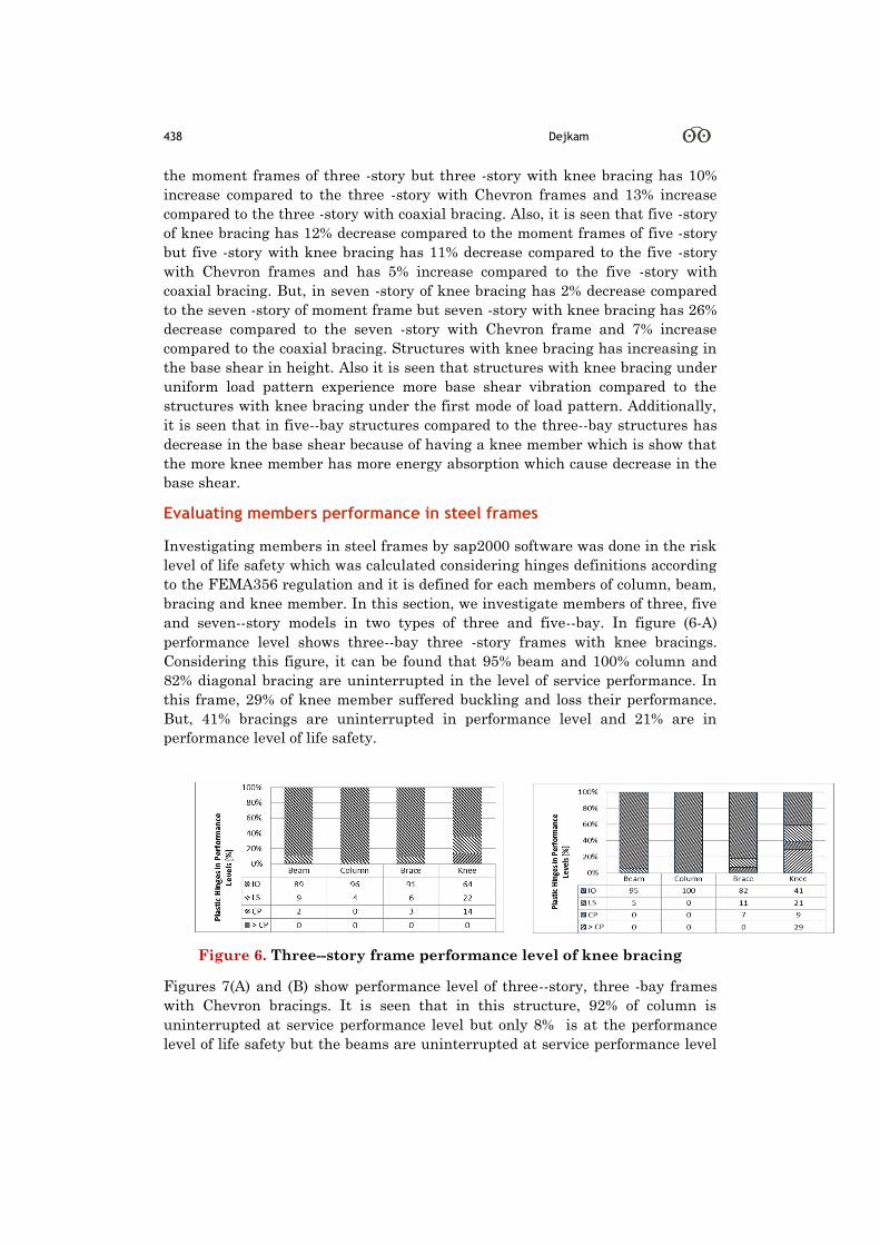
and seven--story models in two types of three and five--bay. In figure (6-A)
performance level shows three--bay three -story frames with knee bracings.
Considering this figure, it can be found that 95% beam and 100% column and
82% diagonal bracing are uninterrupted in the level of service performance. In
this frame, 29% of knee member suffered buckling and loss their performance.
But, 41% bracings are uninterrupted in performance level and 21% are in
performance level of life safety.
Figure 6. Three--story frame performance level of knee bracing
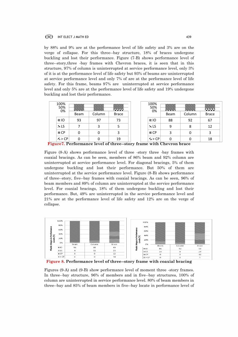
Figures 7(A) and (B) show performance level of three--story, three -bay frames
with Chevron bracings. It is seen that in this structure, 92% of column is
uninterrupted at service performance level but only 8% is at the performance
level of life safety but the beams are uninterrupted at service performance level
INT ELECT J MATH ED 439
by 88% and 9% are at the performance level of life safety and 3% are on the
verge of collapse. For this three--bay structure, 18% of braces undergone
buckling and lost their performance. Figure (7-B) shows performance level of
three--story,three -bay frames with Chevron braces, it is seen that in this
structure, 97% of column is uninterrupted at service performance level, only 3%
of it is at the performance level of life safety but 93% of beams are uninterrupted
at service performance level and only 7% of are at the performance level of life
safety. For this frame, beams 97% are uninterrupted at service performance
level and only 5% are at the performance level of life safety and 19% undergone
buckling and lost their performance.
Figure7. Performance level of three--story frame with Chevron brace
Figure (8-A) shows performance level of three -story three -bay frames with
coaxial bracings. As can be seen, members of 86% beam and 92% column are
uninterrupted at service performance level. For diagonal bracings, 5% of them
undergone buckling and lost their performance. But 50% of them are
uninterrupted at the service performance level. Figure (8-B) shows performance
of three--story, five--bay frames with coaxial bracings. As can be seen, 96% of
beam members and 89% of column are uninterrupted at the service performance
level. For coaxial bracings, 18% of them undergone buckling and lost their
performance. But, 49% are uninterrupted in the service performance level and
21% are at the performance level of life safety and 12% are on the verge of
collapse.
Figure 8. Performance level of three--story frame with coaxial bracing
Figures (9-A) and (9-B) show performance level of moment three -story frames.
In three--bay structure, 96% of members and in five--bay structures, 100% of
column are uninterrupted in service performance level. 80% of beam members in
three--bay and 85% of beam members in five--bay locate in performance level of
Beam Column Brace
IO 88 92 67
LS 9 8 12
CP 3 0 3
> CP 0 0 18
0%50%
100%
Beam Column Brace
IO 93 97 73
LS 7 3 5
CP 0 0 3
> CP 0 0 19
0%50%
100%

440 Dejkam
uninterrupted service and all hinges participated in lateral loading and only 8%
of beam members and 3% of beam in five -bay are on the verge of collapse.
Figure 9. Performance level of moment three -story frame
Figures (10-A) and (10-B) show performance level of five -story frames with knee
bracings. In this structure, 91% of beam members, 100% of column and 89% of
coaxial bracing members are at the performance level of uninterrupted service.
Knee member for three -bay are at the performance level of uninterrupted
service in 77% of cases and 11% undergone destruction. Also, it is seen that at
the five -bay frame, bracings in five-bay are uninterrupted in service by 78% and
only 7% of them are on the verge of collapse; but knee member in five -bay
undergone buckling by 9% and lost their performance.
Figure 10. Performance level of five -story frame of knee bracing
Figure (11-A) show performance level of five –story,three -bay frames with
Chevron bracings. In this structure, 90% of column are uninterrupted in service
performance level and also 96% of beam are uninterrupted in service
performance level and 4% of them are at the performance level of life safety.
Bracings for three -bay bracing frames in 67% of cases are uninterrupted in
service performance level and 10% undergone destruction. But figure (11-B)
shows performance level of five-story, five-bay frames with Chevron bracings. In
this structure, 93% of column are uninterrupted in service performance level
and 80% of bear also are uninterrupted in service performance level and 15% are
at the performance level of life safety. Braces for bracing frames of five-bay are
uninterrupted in service performance level in 67% of cases and 17% of them are
at the performance level of life safety.

INT ELECT J MATH ED 441
Figure 11. Performance level of five -story frame with Chevron brace
Figures (12-A) and (12-B) show performance level of five -story frames with
coaxial braces. In three -bay frame, all member of column and in five -bay 93% of
column are uninterrupted in service performance level but 79% of beam in three
-bay frame and 74% in five -bay are at the uninterrupted service performance
level. Braces for bracing frames of three -bay and for five-bay structures in 57%
of cases are at the uninterrupted service performance level and in other cases,
are at the performance level of life safety.
Figure 12. Performance level of five -story frame with coaxial brace
Figures (13-A) and (13-B) show performance level of moment five -story frames.
In these structures of five -story three -bay, 12% of beam members, are at the
performance level of life safety but 90% of three -bay and 93% of five -bay of
column members -bay are at the uninterrupted service performance level.
Figure 13. Performance level of moment five -story frame
Figures (14-A) and (14-B) show performance level of seven -story frame with
knee braces. In three -bay structure, 90% of column members and in five -bay
structure, 88% of column members are at the uninterrupted service performance
level. Performance of knee members in three -bay bracing was satisfying and in
addition to being stayed in life safety area, causes 50% and five -bay being
stayed at the uninterrupted service performance level by 44%. However, 23% of
knee member for three -bay frame and 35% for five -bay structures have suffered
destruction. In three -bay, 11% of five -bay and 10% of knee members are at the
performance level of collapse.
442 Dejkam
Figure 14. Performance level of seven -story frame of knee brace
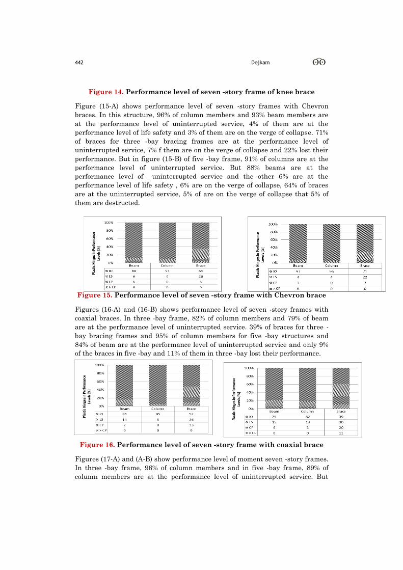
Figure (15-A) shows performance level of seven -story frames with Chevron
braces. In this structure, 96% of column members and 93% beam members are
at the performance level of uninterrupted service, 4% of them are at the
performance level of life safety and 3% of them are on the verge of collapse. 71%
of braces for three -bay bracing frames are at the performance level of
uninterrupted service, 7% f them are on the verge of collapse and 22% lost their
performance. But in figure (15-B) of five -bay frame, 91% of columns are at the
performance level of uninterrupted service. But 88% beams are at the
performance level of uninterrupted service and the other 6% are at the
performance level of life safety , 6% are on the verge of collapse, 64% of braces
are at the uninterrupted service, 5% of are on the verge of collapse that 5% of
them are destructed.
Figure 15. Performance level of seven -story frame with Chevron brace
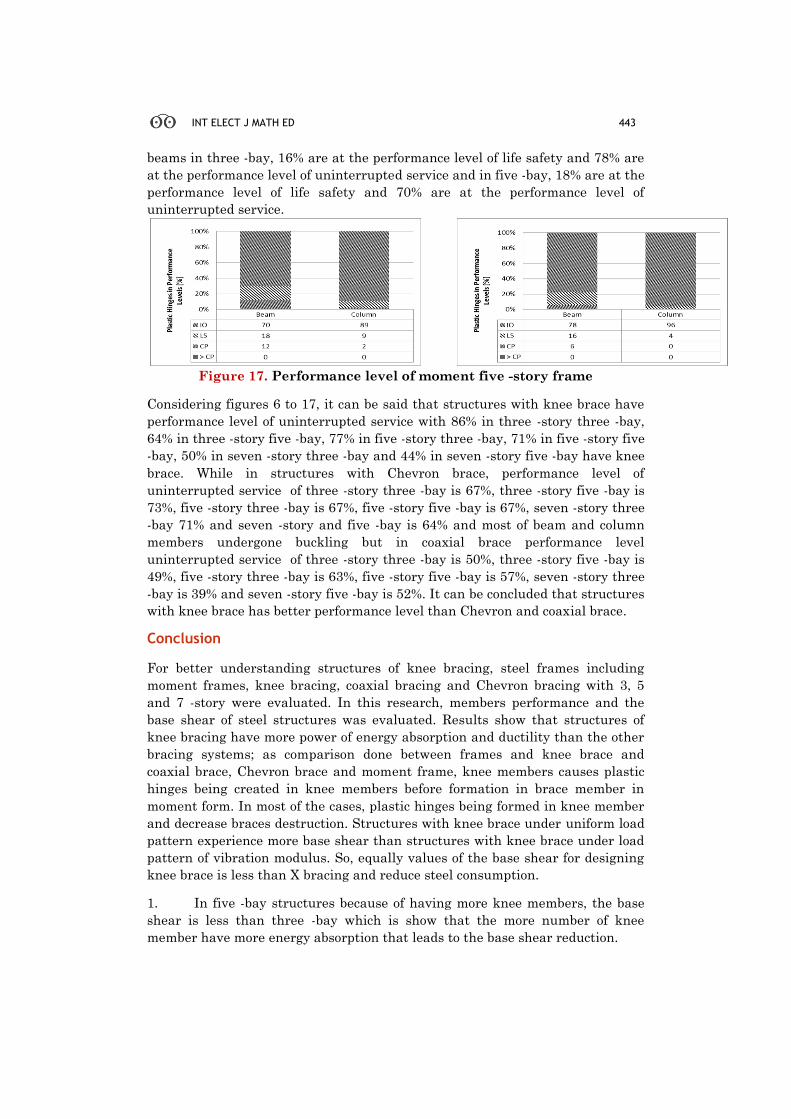
Figures (16-A) and (16-B) shows performance level of seven -story frames with
coaxial braces. In three -bay frame, 82% of column members and 79% of beam
are at the performance level of uninterrupted service. 39% of braces for three -
bay bracing frames and 95% of column members for five -bay structures and
84% of beam are at the performance level of uninterrupted service and only 9%
of the braces in five -bay and 11% of them in three -bay lost their performance.
Figure 16. Performance level of seven -story frame with coaxial brace
Figures (17-A) and (A-B) show performance level of moment seven -story frames.
In three -bay frame, 96% of column members and in five -bay frame, 89% of
column members are at the performance level of uninterrupted service. But
INT ELECT J MATH ED 443
beams in three -bay, 16% are at the performance level of life safety and 78% are
at the performance level of uninterrupted service and in five -bay, 18% are at the
performance level of life safety and 70% are at the performance level of
uninterrupted service.
Figure 17. Performance level of moment five -story frame
Considering figures 6 to 17, it can be said that structures with knee brace have
performance level of uninterrupted service with 86% in three -story three -bay,
64% in three -story five -bay, 77% in five -story three -bay, 71% in five -story five
-bay, 50% in seven -story three -bay and 44% in seven -story five -bay have knee
brace. While in structures with Chevron brace, performance level of
uninterrupted service of three -story three -bay is 67%, three -story five -bay is
73%, five -story three -bay is 67%, five -story five -bay is 67%, seven -story three
-bay 71% and seven -story and five -bay is 64% and most of beam and column
members undergone buckling but in coaxial brace performance level
uninterrupted service of three -story three -bay is 50%, three -story five -bay is
49%, five -story three -bay is 63%, five -story five -bay is 57%, seven -story three
-bay is 39% and seven -story five -bay is 52%. It can be concluded that structures
with knee brace has better performance level than Chevron and coaxial brace.
Conclusion
For better understanding structures of knee bracing, steel frames including
moment frames, knee bracing, coaxial bracing and Chevron bracing with 3, 5
and 7 -story were evaluated. In this research, members performance and the
base shear of steel structures was evaluated. Results show that structures of
knee bracing have more power of energy absorption and ductility than the other
bracing systems; as comparison done between frames and knee brace and
coaxial brace, Chevron brace and moment frame, knee members causes plastic
hinges being created in knee members before formation in brace member in
moment form. In most of the cases, plastic hinges being formed in knee member
and decrease braces destruction. Structures with knee brace under uniform load
pattern experience more base shear than structures with knee brace under load
pattern of vibration modulus. So, equally values of the base shear for designing
knee brace is less than X bracing and reduce steel consumption.
1. In five -bay structures because of having more knee members, the base
shear is less than three -bay which is show that the more number of knee
member have more energy absorption that leads to the base shear reduction.

444 Dejkam
2. Knee member in KBF frames has drastic drop after yielding because of
ductile fuse formation on them. Accordingly, energy depreciation is done for
forming moment plastic hinges and damages small portion of the building which
can be repaired or replaced easily. So, in this sense, KBF frames are better over
the similar CBF frames.
3. Structures with knee brace under uniform load pattern experience more
base shear over the structures with knee brace under modulus load pattern of
vibration.
4. The base shear of three -story has 8% decrease over the three -story with
moment frames.
5. The base shear of three -story has 10% increase over the three -story
with Chevron frame and 13% increase over the three -story with coaxial brace.
6. The base shear of five -story with knee brace has 11% decrease over the
five -story with moment frame.
7. The base shear of five -story with knee brace has 11% decrease over five -
story with Chevron frame and 5% increase over the five -story with coaxial
brace.
8. The base shear with seven -story with knee brace has 26% decrease over
the seven -story with Chevron frame and has 7% increase over then coaxial
brace. Generally, the knee bracing system is a bracing system which can supply
appropriate hardness and high ductility for structure if effective parameters are
chosen and after earthquake, it can be reused with replacing knee member.
Disclosure statement No potential conflict of interest was reported by the authors.
Notes on contributors
Behzad Dejkam
Faculty member of Civil Engineering University of velayat, Iranshahr, Iran.
References
Kalkan E. and Kunnath S. K. (2004), "Method of modal combinations for pushover analysis of
buildings," in Proc. Of the 13 th World Conference of Earthquake Engineering.
Khatib I. F., Mahin S. A., and Pister K. S. (1988), Seismic behavior of concentrically braced steel
frames vol. 88: Earthquake Engineering Research Center, University of California.
Uriz P. (2008), Toward earthquake-resistant design of concentrically braced steel-frame structures:
Pacific Earthquake Engineering Research Center.
Aristizabal-Ochoa J. D. (1986), "Disposable knee bracing: improvement in seismic design of steel
frames," Journal of Structural Engineering, vol. 112, pp. 1544-1552.
Roeder C. W.and Popov E. P. (1978), "Eccentrically braced steel frames for earthquakes," Journal of
the Structural Division, vol. 104, pp. 391-412.
Naeemi M. and Bozorg M. (2009), "Seismic Performance of Knee Braced Frame," Proceedings of
World Academy of Science: Engineering & Technology, vol. 50,pp 976-980.
Kim J.and Seo Y. (2003), "Seismic design of steel structures with buckling-restrained knee braces,"
Journal of Constructional Steel Research, vol. 59, pp. 1477-1497.
Balendra T., Sam M. T., and Liaw C. Y. (1990), "Diagonal brace with ductile knee anchor for
aseismic steel frame," Earthquake engineering & structural dynamics, vol. 19, pp. 847-858.
Agency F. E. M. (2000), "Prestandard and Commentary for the Seismic Rehabilitation of Buildings:
FEMA-356," ed: Federal Emergency Management Agency Washington.
Code U. B. (1997), "UBC 97, Code for Seismic Design of Buildings (1997 Edition)," Structural
Engineering Design Provisions, vol. 2.
Balendra T., Sam M.-T., Liaw C.-Y., and Lee S.-L. (1991), "Preliminary studies into the behaviour of

INT ELECT J MATH ED 445
knee braced frames subject to seismic loading ",Engineering Structures, vol. 13, pp. 67-74.
FEMA A. (2005), "440, Improvement of nonlinear static seismic analysis procedures," ed: Federal
Emergency Management Agency, Washington DC.
Elnashai A. S. (2001), "Advanced inelastic static (pushover) analysis for earthquake applications,"
Structural engineering and mechanics, vol. 12, pp. 51-70.
Krawinkler H.and Seneviratna G. (1998), "Pros and cons of a pushover analysis of seismic
performance evaluation," Engineering Structures, vol. 20, pp. 452-464
Chopra A. K.and Goel R. K. (2002), "A modal pushover analysis procedure for estimating seismic
demands for buildings," Earthquake engineering & structural dynamics, vol. 31, pp. 561-582.
Chopra A. K., Goel R. K., and Chintanapakdee C. (2004), "Evaluation of a modified MPA procedure
assuming higher modes as elastic to estimate seismic demands," Earthquake Spectra, vol. 20,
pp. 757-778.
Ghodrati,A and Eghbali,M (2011)"New method of two line pushover for seismic evaluation of steel
frames. 5th natinal congress of construction engineering. Mashhad.