Embed Size (px)
Citation preview

Broad Lane, Sheffield, S3 7HQTelephone:+44 (0)114 289 2000Facsimile: +44 (0)114 289 2500
Investigation into the effectiveness ofmodular hygiene units
HSL/2001/16
Environmental Measurement Group
© Crown copyright 2001
D Bard (PhD)
B TyleeProject Leader:

Summary
Objectives
In recent years, small modular hygiene units have become available to the asbestos removalindustry and an increased number of licensed removal contractors want to use them. Therewas a concern that modular units may be too small and/or poorly equipped to allow effectivedecontamination of the asbestos removal workers. The aim of this project was to assesscompliance of modular hygiene units in line with current HSE guidance (which is underrevision) and make recommendations for changes to EH47.
Main Findings
All the units which were supplied consisted of three modules joined together to provide a‘clean’ area, shower area and a ‘dirty’ area and had separate air extraction and watermanagement systems.
Size of modular hygiene units
To enable satisfactory showering and decontamination, each compartment of the unit shouldhave dimensions at least 1m x 1m x 2m (height). If more than a couple of workers are usingthe facility and all have to leave their clothes and other items in the unit, then it should be atleast 1m x 1.5m x 2m (height).
Construction and layout of modular hygiene units
In general, the layout and provision (e.g. cupboards, seats, hooks, mirrors, etc) of modularhygiene units were fairly good. Only the shower compartment of one unit did not havesuitable provision (e.g. hooks, sinks) , for hanging towels, RPE and holding shampoo, nailbrush, soap, etc. The units were constructed of impervious materials providing a smoothsurface and seemed fairly robust. However, clips and wingnuts fastening panels togethermight be damaged after time, especially during transportation. In such cases, care should betaken to check and ensure that the roof units are tightly engaged and there are no gaps, whichcould give rise to leaks. On the unit supplied by the company B, the panels were also tiedtogether on the inside by additional metals bars.
Units with non-self closing doors, fitted with latches, were difficult to close and might be leftopened on asbestos removal site, increasing the risks of contamination of the ‘clean’ area withasbestos.
On site, workers placed storage lockers, which had no designated attached positions in units,close to the air extraction ports or ventilation grilles, reducing the airflow movement andefficiency through the unit. Lockers should have a designated position in the unit and be fixedin place.
Storage lockers / boxes should not be present in the dirty area. All fittings should be designedso they can be easily cleaned (e.g. the sinks should be fitted with a drainage pipe and thestorage locker replaced by a bench in the ‘dirty area’).
The provision of a limited number of outlets for the connection of the air extraction system tothe hygiene unit can lead to difficulties in attaching the intervening space to the hygiene unit.
Extract ventilation
The measurements of velocity / airflow rate at the grilles gave only a partial indication of howwell the modular hygiene units performed. These measurements did not give informationabout airflow rate through the shower compartment and ‘clean’ area, as a high percentage ofthe air was also entering through cracks, joints and around doors. An accurate measure of theairflow rates through the unit could only be obtained with a tracer gas technique.
The airflow rate measured at the air extraction unit when connected to the hygiene unit was 50- 70% of the recommended value set out in EH47. However, due to the small volume of theunits, the number of air changes per hour through the ‘dirty’ area was between 80 - 105. Norecommendation is made in EH 47 concerning the minimum number of air changes per hour.However, German guidance [4] recommends 10 air changes per hour in the shower compart-ment and in the ‘dirty’ area. A French publication [5] sets out a minimum of 6 air changesthrough the shower. This means that if a worker spends 5 minutes in the shower, the minimumnumber of air changes should be 6 in that period or 72 air changes per hour. The number of airchanges through the ‘dirty’ area of the modular hygiene units assessed in this project wasconsidered satisfactory.
Velocity and airflow rates measured at the grilles were low compared to the values obtained atthe air extraction unit and varied across the hygiene unit because of air being drawn throughleaks. The percentage of air passing through the grilles(s) positioned between the dirty areaand the shower compartment was only between 15 to 45 % of the total airflow.
The incorrect fitting of flaps between door panels and the grilles considerably reduced theairflow rate through the grilles, forcing air to enter by doors and gaps.
The pressure difference increased from the ‘clean’ area to the ‘dirty’ area so air moved safelyfrom an area of no contamination to an area of high contamination. However, the negativepressure in the ‘dirty’ area was very high compared to the value that could be expected in theenclosure (about -5 Pa ). This meant that contaminated air from the working area might bedrawn through gaps (e.g. around the outside door of ‘dirty’ area) into the hygiene unit. There-fore, the hygiene unit should not be directly attached to the enclosure and should only beconnected to the work area via an intervening space or tunnel with a plastic airlock section.Openings fitted with flaps should be provided in the intervening space to permit the supply ofclean replacement air to the work area and the hygiene unit. In the case of a negative pressure,which will be higher in the ‘dirty’ area than in the work area, the air will be drawn fromopenings in the tunnel through the airlock section to the hygiene unit.
Also bigger grilles would reduce the pressure drop through the unit, giving rise to a smallerpressure difference between the dirty area and the intervening space/enclosure and wouldimprove the airflow rate.
Water management system
The showers, in all units, were effective (e.g. pressure, flow, temperature) and would alloweffective decontamination of the workers.
Main Recommendations
Size of modular hygiene unit for practical use.
1. The minimum size of each compartment, which we would recommend, is 1m x 1m x 2m(height) allowing one worker to use it at a time. However, compartments with dimensions 1mx 1.5m x 2m (height) or 1.5m x 1.5m x 2m (height) offer a more comfortable area in whichdecontamination can take place. Such units should only be used by one person at a time.
Airflow
2. The current guidance document recommends an airflow of 0.1 m3/s through the hygieneunit. However, depending on the size of the unit, the number of air changes per hour will vary.Therefore, it might be more desirable to recommend an airflow for a defined volume ornumber of air changes / hour. It is recommended to have between 50 and 100 air changes perhour in the ‘dirty area’.
3. The current guidance document is unclear about which flow rate should be measured.When the air extraction unit is connected to the hygiene unit, the airflow rate drops comparedwith the airflow rate value measured at the air extraction unit with its inlets unsealed andunconnected.
Grilles
4. The current guidance document recommends grille sizes of 6 in x12 in (15 cm x 30 cm)with a minimum of 8 in x 9 in (20 cm x 23 cm) for pressure/gravity operated flaps. We wouldrecommend even bigger grilles as the modular units assessed in this project had sizes of 24 cmx 24 cm for the hygiene unit 1 and 13 cm x 12 cm (two grilles with flaps provided per panel)for the hygiene units 2 and 4.
Lighting
5. Artificial lighting should be provided in all compartments.

Position and connection to the enclosure
6. Modular hygiene units should not be directly attached to the enclosure and should beconnected to the work area via an intervening space or tunnel and an airlock section, due tothe large pressure drop which generally occurs through modular hygiene units.
7. The dirty area should have at least three outlets (two on the sides and one in front of the‘dirty’ end panel / door) for the connection of the air extraction unit to the hygiene unit.
8. The air extraction unit was connected to the air extract port of the modular hygiene facilityby means of a flexible tube. There is no current specification for this. Future guidance shouldstate that the tubing should be well sealed to the outlet spigot and should be of a reasonablelength to avoid any twist / bending which might reduce the effectiveness of the air extractionunit.
Positioning of provisions
9. It is essential that provisions such as lockers should not block or be placed close to the airextraction ports or ventilation grilles.
10. In the modular unit assessed during this project, these doors opened into the showercompartment.
Water management
12. It is recommended that the water management system is able to pump simultaneously theclean water in and the waste water out of the shower compartment.
11. It is essential that the waste water should be filtered for asbestos fibres before being sent tothe drainage system.

Contents
51APPENDIX 3 - Measurement of number of air changes per hourin a new hygiene unit (trailer) . . . . . . . . . . . . . . . . . . . . . . . . . . . . . . . . . . . . .
47APPENDIX 2 - Applicability of EH47 to modular hygiene units . . . . . . . . .42
APPENDIX 1 - Laboratory comparison of three modular hygieneunits to EH47 . . . . . . . . . . . . . . . . . . . . . . . . . . . . . . . . . . . . . . . . . . . . . . . . . . .
41References . . . . . . . . . . . . . . . . . . . . . . . . . . . . . . . . . . . . . . . . . . . . . . . . . . . .375. CONCLUSION . . . . . . . . . . . . . . . . . . . . . . . . . . . . . . . . . . . . . . . . . . . . . . .364.2.2. General observations . . . . . . . . . . . . . . . . . . . . . . . . . . . . . . .364.2.1. The site . . . . . . . . . . . . . . . . . . . . . . . . . . . . . . . . . . . . . . . . . . .364.2. Barrow site visit of modular hygiene unit 2 . . . . . . . . . . . . . . . . . .354.1.3. On site measurements . . . . . . . . . . . . . . . . . . . . . . . . . . . . . .324.1.2. General observations . . . . . . . . . . . . . . . . . . . . . . . . . . . . . . .314.1.1. The site . . . . . . . . . . . . . . . . . . . . . . . . . . . . . . . . . . . . . . . . . . .314.1. Moor House site visit of modular hygiene unit 4 . . . . . . . . . . . . .314. SITE VISIT . . . . . . . . . . . . . . . . . . . . . . . . . . . . . . . . . . . . . . . . . . . . . . . . . .283.5. Modular hygiene unit 3 (a unit used for transit facilities) . . . . . . .283.4.4. Electrical components . . . . . . . . . . . . . . . . . . . . . . . . . . . . . . .273.4.3. Water management . . . . . . . . . . . . . . . . . . . . . . . . . . . . . . . . .253.4.2. Extract ventilation . . . . . . . . . . . . . . . . . . . . . . . . . . . . . . . . . . .213.4.1. General arrangements and construction . . . . . . . . . . . . . . .213.4. Modular hygiene unit 2 . . . . . . . . . . . . . . . . . . . . . . . . . . . . . . . . . .21
3.3.3. Water management system / electricalcomponents . . . . . . . . . . . . . . . . . . . . . . . . . . . . . . . . . . . . . . . . . . . . .
183.3.2. Extract ventilation . . . . . . . . . . . . . . . . . . . . . . . . . . . . . . . . . . .163.3.1. General arrangements and construction . . . . . . . . . . . . . . .163.3. Modular hygiene unit 1 by company B . . . . . . . . . . . . . . . . . . . . .163.2.4. Electrical components . . . . . . . . . . . . . . . . . . . . . . . . . . . . . . .153.2.3. Water management system . . . . . . . . . . . . . . . . . . . . . . . . . .133.2.2. Extract ventilation . . . . . . . . . . . . . . . . . . . . . . . . . . . . . . . . . . .
83.2.1. General arrangements and construction . . . . . . . . . . . . . . . .83.2. Modular hygiene unit 1 supplied by company A . . . . . . . . . . . . . .83.1.2. Air extraction unit 2 . . . . . . . . . . . . . . . . . . . . . . . . . . . . . . . . . .73.1.1. Air extraction unit1 . . . . . . . . . . . . . . . . . . . . . . . . . . . . . . . . . . .73.1. Air extraction unit . . . . . . . . . . . . . . . . . . . . . . . . . . . . . . . . . . . . . . . .6
3. ASSESSMENT OF HYGIENE UNITS IN LABORATORYCONDITIONS . . . . . . . . . . . . . . . . . . . . . . . . . . . . . . . . . . . . . . . . . . . . . . . . . . .
62.3. Lighting . . . . . . . . . . . . . . . . . . . . . . . . . . . . . . . . . . . . . . . . . . . . . . . .62.2. Airflow measurements . . . . . . . . . . . . . . . . . . . . . . . . . . . . . . . . . . .12.1. Check list . . . . . . . . . . . . . . . . . . . . . . . . . . . . . . . . . . . . . . . . . . . . . . .12. BACKGROUND . . . . . . . . . . . . . . . . . . . . . . . . . . . . . . . . . . . . . . . . . . . . . . .11. INTRODUCTION . . . . . . . . . . . . . . . . . . . . . . . . . . . . . . . . . . . . . . . . . . . . . .
1
1. INTRODUCTION
A ‘hygiene unit’ is defined in the Guidance Note EH 47 [1], has being ‘a mobile, fixed or temporary facility which is provided to enable people removing asbestos insulation and asbestos coatings to change from normal clothing into protective clothing and respiratory protective equipment (RPE) before entering the asbestos contaminated work area, and to effectively decontaminate themselves when leaving the work area’.
In recent years, small modular hygiene units have become available to the asbestos removal industry. An increased number of licensed removal contractors want to use these units on sites in order to save costs and to provide decontamination closer to the removal, in particular where access is restricted. The current guidance note EH47 [1] (entitled ‘The provision, use and maintenance of hygiene facilities for work with asbestos insulation and coatings’) was written before these units were introduced. This guidance stipulates that, where practical, hygiene facilities should be purpose-built unit (e.g. trailer) attached to the work area and should only be used for the decontamination of workers. Where it is not possible to position a purpose-built unit close to the work area, then, consideration may be given to use temporary constructed facilities such as modular units. Any temporary facilities should be to the same standard as the purpose built units.
Modular hygiene units are panel-based systems, which enable rapid construction of hygiene and shower facilities on site. The panels reduce the space required for storage and transportation. Some modular units can be assembled in different configurations (e.g. straight line, L shape) or be extended to more than three compartments. The air extraction unit, the water management system and the electrical/sockets system are usually positioned outside the hygiene facility and purchased individually.
There was a concern that modular units may be too small and/or poorly equipped to allow effective decontamination of the asbestos removal workers. The aim of this project was to assess compliance of modular hygiene units with the HSE Guidance Note EH 47 [1] which is under revision. Modular hygiene units set up in the laboratory and on site were assessed using a check list developed from the Guidance Note EH47 [1] and by taking airflow measurements.
This report compares four units to the standard. Appendix 1 is the laboratory comparison of three modular hygiene units to EH47. Appendix 2 is the applicability of EH47 to modular hygiene units. Appendix 3 is the measurement of the number of air changes per hour in a new hygiene unit (trailer).
2. BACKGROUND 2.1. Check list A check list (see table 1) was developed from Guidance Note EH 47 [1].
2
EH 47
Check list
• General arrangements and construction - The hygiene unit should have ventilation, showering, heating and water filtration systems. Basic design of a hygiene unit - A hygiene unit consists of a minimum of three physically separated
compartments (a ‘clean’ area, a shower area and a ‘dirty’ area); - Access between the compartments should be by self-closing doors (self-
closing doors on both sides of the shower compartment (between the ‘clean’ area and the ‘dirty’ area));
- Access to the ‘clean’ area and ‘dirty’ area should be by an external door, opening outwards. The ‘dirty’ area should be provided with a self-closing door.
- The inside doors between the compartments and the outside door to the ‘dirty’ area should be well-fitting to minimise air and dust leakage.
Three compartments hygiene unit The ‘clean’ area should have: - fixed seating, facilities for hanging and drying decontaminated RPE / drying
outdoor clothing and safe storage for personal valuables and clothes; - respirator battery charging points (a system should be established to identify
fully charged and rundown batteries); - a mirror to help workers adjust their RPE. The shower area should have: - a shower tray and a thermostatically controlled shower, a rose showerhead; - hooks for hanging towels and RPE undergoing decontamination; - shampoos, soaps, sponges, nails brush, towels; a bag or slot for disposal of
used filter; a bag for dirty towels.
- Measure the size (length x base x height) of all modular
units and overall size. - Check self-closing doors. - Comment on external doors. Do they open outwards? - Check doors fitting. - Measure seats dimension; count numbers of seats,
hooks, lockers etc. - Count numbers. - To check. - To check. - Count numbers of hooks. - Is there enough space with one or two waste disposal
bags on floor?
3
The ‘dirty’ area should have: - an air extraction and filtration unit; - fixed seating; - a wash hand basin with hot and cold running water to wash hands before
entering the shower area; - suitably marked bags for contaminated clothing. Heating - Adequate heating should be used for the hygiene unit. - Heating appliances should be easily cleaned and positioned so that, dust does
not accumulate in inaccessible areas - If LPG fired heating equipment used, then only appliances of the room
sealed balanced flue type should be installed (should preferably fitted with a flame failure device, if not appliance should be provided with a separate on/off valve).
- If LPG used, cylinders should be stored externally in an adequately secured and well-ventilated cupboard or storage rack.
- Unflued or open flued gas heaters, discharging combustion products into the hygiene unit, should never be used due to carbon monoxide poisoning.
Construction - The hygiene unit must be cleaned easily and effectively. Asbestos dust must
not accumulate in inaccessible places. Features of the hygiene unit: - The internal walls, ceilings and floors should be made of smooth and
impervious materials. - Angles should be covered for easy cleaning.
- Measure seats dimension and count number of seats. - Is there enough space with a waste disposal bag on
floor? - Is there a sink with hot/cold water in ‘dirty’ end or
shower section? - Comment on any potential dust traps. - To check. - Comment on storage location of LPG cylinders. - To check. - Comment on construction material, construction quality
and how well modular units fit together. Comment on any potential dust traps.
- To check / comment. - To check / comment.

4
- Ledges and grooves should be avoided. - Drainage holes should be provided in the floor. - Lighting should be easily cleaned and positioned so that dust traps are not
created. - The windows should be non-opening, unbreakable and fitted flush with the
inner wall surface. - The doors must not be propped open or the self-closing mechanism rendered
ineffective. - Lighting should be adequate. - Light switches should be in the ‘clean’ area or two-way in the ‘clean’ and
‘dirty’ areas. • Extract ventilation - It is very important to maintain an airflow from the ‘clean’ to the ‘dirty’ area
to prevent contaminated air entering the ‘clean’ area. - The air extraction should discharge through a high efficiency particular
arrestor (HEPA) or absolute filter (it is advantageous to fit a pre-filter between the air inlet to the extraction unit and the HEPA filter).
- The air extraction should be positioned at low level (but sufficiently above floor level not to be damaged by water during floor cleaning); the area beneath the unit should be able to be cleaned.
- The airflow should be of 0.1 m3/s to ensure an efficient ventilation of the hygiene unit.
- The replacement air should enter the facility by a system of one way grilles with pressure/gravity operated flaps; the recommended grilles size is 6 in x 12 in; the minimum size for grilles with pressure/gravity operated flaps is 8 in x 9 in.
- To enable the extraction to work effectively, one way grilles should be situated in the internal walls and an air inlet grille in the clean area external
- To check / comment. - To check / comment. - To check / comment. - To check / comment. - To check / comment. - Measure intensity of lighting in each compartment. - To check. - Establish fan specification. - Comment on air extraction position. - Establish air change per hour in unit and assess the
airflow. - Measure size of grilles, specify location (i.e. low or
high level) and comment on type of grille (e.g. pressure or gravity operated.
- Assess airflow movement in unit. Does it flow fluently
throughout unit (e.g. up and down to grills)? Does poor
5
wall. • Water supply - Adequate heating should be used for the water - The mains water supply should be connected to the hygiene unit. - Connection to the mains water supply should be flexible joints. - The water from the shower should be filtered before being discharged. • Electrical power to the hygiene unit – lighting - The hygiene unit should be connected to an electrical supply (mains and
generators). - The electrical power should be unswitched to run continuously or
interconnected with the lighting circuit. - Electrical appliances should either be double insulated or be permanently
wired in to the circuit and switched. - The electrical system within the facility should be protected by earth
bonding and earth leakage circuit breakage. - It is desirable to have a time delay in the circuit that allows the extract unit to
run for at least 15 minutes after use.
fitting sections lead to air passing of some sections? - To check. - Is the water filtered? Type of filter? Where does the
waste water discharge? - Is the unit fitted with a RCCB with 30 mA trip? - To check. - To check. - Is the unit earthed? - Does the fan operate for 15 minutes after lights are
switched off?
Table 1. Check list for the assessment of modular hygiene unit.

6
2.2. Airflow measurements � Pressure at the air extraction unit / airflow The pressure at the air extraction unit was measured using a duct fitted with a Wilson flow grid. The airflow rate (Q) was given by:
a)pressure(P27.034/h)Q(m3��
� Number of changes through the hygiene unit The number of changes per hour through the unit was given by:
/s)minunitationdecontaminofV(volume/s)minQ(airflowhour)perchangesofN(number 3
3
�
� Velocity at grilles In laboratory conditions, the velocity at the grilles was measured using a rotating vane fitted with an aircone flow hood, connected to an anenometer. The airflow was obtained by multiplying the velocity with a factor given by the manufacture.
On site, direct measurements at the grilles were taken using a digital anometer.
� Difference of pressure between the hygiene unit and the atmosphere/laboratory The difference in pressure between the unit and the atmosphere/laboratory was measured for each compartment and obtained by taking readings through holes in hygiene units.
2.3. Lighting The level of lighting was measured in Lux with a ISO TECH ILM 350. The measurements were taken at the middle of each compartment, about 1 metre above the floor level.
3. ASSESSMENT OF HYGIENE UNITS IN LABORATORY CONDITIONS
Several modular hygiene units, supplied by two companies (company A and company B), were set up in the laboratory. The hygiene units were assessed using a check list developed from the Guidance Note EH47 [1] and by taking airflow measurements.
Company A hires hygiene units but is not itself a manufacturer of these. This company supplied: - two modular hygiene units having their own water management and electrical systems:
- the hygiene unit type 1 (this unit had been used on asbestos removal sites for personal decontamination);
- the hygiene unit type 2; - an air extraction unit (air extraction unit 1). Company B is a specialist manufacturer of decontamination showers and asbestos removal equipment. This company also supplied: - two modular hygiene units:

7
- the hygiene unit type 1 (a unit directly provided from the production line having its own management and electrical systems);
- the hygiene unit type 3 (a unit used for transit facilities); - an air extraction unit (air extraction unit 2).
3.1. Air extraction units
3.1.1. Air extraction unit 1
The air extraction unit 1 (see figure 1), was provided by company A. The ventilation system discharged air from the hygiene unit through a HEPA filter and was fitted with a pre-filter between the air inlet to the extraction unit and the HEPA filter. Back draught flaps were fitted to the equipment to prevent possible reverse flow. This unit had a volume flow control, which was turned to the maximum during measurements.
Figure 1. Air extraction unit 1
The air extraction unit 1 was new and had never been used on site previously. The extraction capability specified by the manufacture was 300 cfm (0.14 m3/s). The pressure at the air extraction unit was measured. The ventilation unit was not connected to the hygiene unit and the caps of the inlets were removed. The pressure was 122.3 Pa giving an airflow rate of 0.083 m3/s, which was lower than the recommended airflow rate of 0.1 m3/s set out in the EH47.
3.1.2 Air extraction unit 2
The air extraction unit 2 (see figure 2), was provided by company B.
Figure 2. Air extraction unit 2
The air extraction unit 2 discharged air from the hygiene unit through a HEPA filter and was fitted with a pre-filter. This unit had a running time meter and a colour coded pressure gauge showing the filter condition and indicating when the filters need changing.
The pressure at the air extraction unit was measured (the ventilation unit was not connected to the hygiene unit). The pressure was 138 Pa giving an airflow of 0.088m3/s.
8
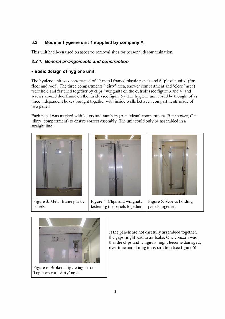
3.2. Modular hygiene unit 1 supplied by company A
This unit had been used on asbestos removal sites for personal decontamination.
3.2.1. General arrangements and construction
� Basic design of hygiene unit
The hygiene unit was constructed of 12 metal framed plastic panels and 6 ‘plastic units’ (for floor and roof). The three compartments (‘dirty’ area, shower compartment and ‘clean’ area) were held and fastened together by clips / wingnuts on the outside (see figure 3 and 4) and screws around doorframe on the inside (see figure 5). The hygiene unit could be thought of as three independent boxes brought together with inside walls between compartments made of two panels.
Each panel was marked with letters and numbers (A = ‘clean’ compartment, B = shower, C = ‘dirty’ compartment) to ensure correct assembly. The unit could only be assembled in a straight line.
Figure 3. Metal frame plastic panels.
Figure 4. Clips and wingnuts fastening the panels together.
Figure 5. Screws holding panels together.
Figure 6. Broken clip / wingnut on Top corner of ‘dirty’ area
If the panels are not carefully assembled together, the gaps might lead to air leaks. One concern was that the clips and wingnuts might become damaged, over time and during transportation (see figure 6).

9
The unit comprised three separate compartments and access between them were all by self-closing hinged door with ventilation grilles. Each compartment was about 0.96m x 0.82m x 2.04m (measurements taken inside the unit) with door openings of about 1.60m x 0.49m (see figure 7). The overall size of the unit was about 3.20m x 0.86m x 2m (measurements taken outside the unit).
The doors were held closed by magnets stuck to the frames and doors. The ‘dirty’ area and ‘clean’ area were provided with outward opening, self-closing external doors (see figures 8 and 9). The inside doors between the separate compartments opened towards the shower compartment.
External doors were clearly marked “Clean end” and “Dirty end” and had an “Entry Prohibited” graphic. The ‘clean’ end external door was fitted with a door-closer.
air extraction unit
0.96m
0.82m
grille 9.5 cm of diameter
2.04
m
1.60
m
0.49m
Dirty areaShower compartmentClean area
Figure 7. Dimensions of the modular hygiene unit 1 (measurements taken inside the unit)
Figure 8. ‘Clean’ end
Figure 9. ‘Dirty’ end

10
The decontamination unit had its own ventilation, showering, heating and water filtration systems.�
� Layout of compartments
‘Clean’ area - The ‘clean’ area had a locker with two compartments (92 x 25 x 51 cm) which could be used as a bench (see figure 10). The locker was fixed to the unit wall by means of screws (accessible from the outside of the unit). There were two hooks (see figure 11), one mirror (see figure 12) and an electric heater protected by a grid (see figure 13). There were no battery charging points.
Figure 10. Two compartments locker
Figure 11. Hooks
Figure 12. Mirror
Figure 13. Heater protected by a grid and two compartment locker
Shower compartment - The shower compartment consisted of a rose shower-head connected by a flexible tube to a water management system situated outside the hygiene unit (see figures 14 and 15). Only one hook was provided for hanging towels and RPE undergoing decontamination. The plastic sink for placing and cleaning objects, provided by the company A, was too large to enable the opening of internal doors in the shower compartment and therefore was not fitted in. There was not much space for leaving a waste bag on the floor for contaminated filters and towels.

11
Figure 14. Rose shower head
Figure 15. Connection to water management system on outside of unit
‘Dirty’ area - The ‘dirty’ area had a board (96 cm x 23.5 cm) at a height of 53.5 cm as a seating arrangement and an electrical heater protected by a grid (see figure 16). The board was not fixed in the unit wall, however, holes for screws were provided. There were two hooks and a mirror. The air extraction unit was designed to be situated outside the unit and was connected to the ‘dirty’ area at low level via a flexible tube (see figure 17). There was limited space for a waste bag on floor.
Figure 16. Seating arrangement and electrical heater
Figure 17. Connection for air extraction unit.
The general arrangement in the three compartments is summarized in the figure below (see figure 18).

12
Mirror Shower rose
HooksHeater
Seat
Hook
Hooks
MirrorHeater
Seat/locker
DIRTY AREASHOWER
COMPARTMENT
CLEAN AREA(2)(3)(4)
(1)
Figure 18. General arrangement of the modular hygiene unit 1.
�
� Construction
Internal walls were constructed of impervious materials providing a smooth surface. The floor was covered with a non-slip surface and a plastic mat was placed in each compartment. A drain was provided in the shower compartment (see figure 19). However, no drain was present in the ‘dirty’ and ‘clean’ areas.
There was no light fitted through the facility. The transparent ceiling allowed light to come in the hygiene unit (see figure 20).
Figure 19. Drainage hole - Shower compartment
Figure 20. Ceiling
Compartment Intensity (Lux) ‘Clean’ area 60 Lux Shower area 70 Lux ‘Dirty’ area 75 Lux
The lighting levels in each compartment (see table 2) were slightly low compared with the minimum recommended lighting levels of 100-150 for circulation areas/entrances, lobbies, waiting areas [3].
Table 2. Light intensity measured in each compartment

13
� Potential dust trap
Dust might be trapped in small gaps between panels or panels and roof units if those are not assembled and fastened together correctly.
The locker/seat in the ‘clean’ area was positioned on the plastic mat leaving a gap underneath which could trap dust. Moreover, the locker will need to be unscrewed and removed for cleaning. However the ‘clean’ area should not be contaminated with asbestos.
3.2.2. Extract ventilation The outside door to the ‘clean’ area and the inside doors between compartments were fitted with one way grilles (see figures 21 to 23). The grilles were positioned to allow a diagonal ventilation through the unit (see figure 7): - ‘low’ position for grilles on outside door ‘clean’ area and inside door of shower
compartment/’dirty’ area; - ‘high’ position for grilles on inside door of shower compartment/’clean’ area. Each grille had a size of 24.5 cm x 24.5 cm, which was within the recommended sizes set out in EH47.
Figure 21. Inside door of ‘clean’ area / shower compartment
Figure 22. Inside door of ‘dirty’ area / shower compartment
Figure 23. Grille
14
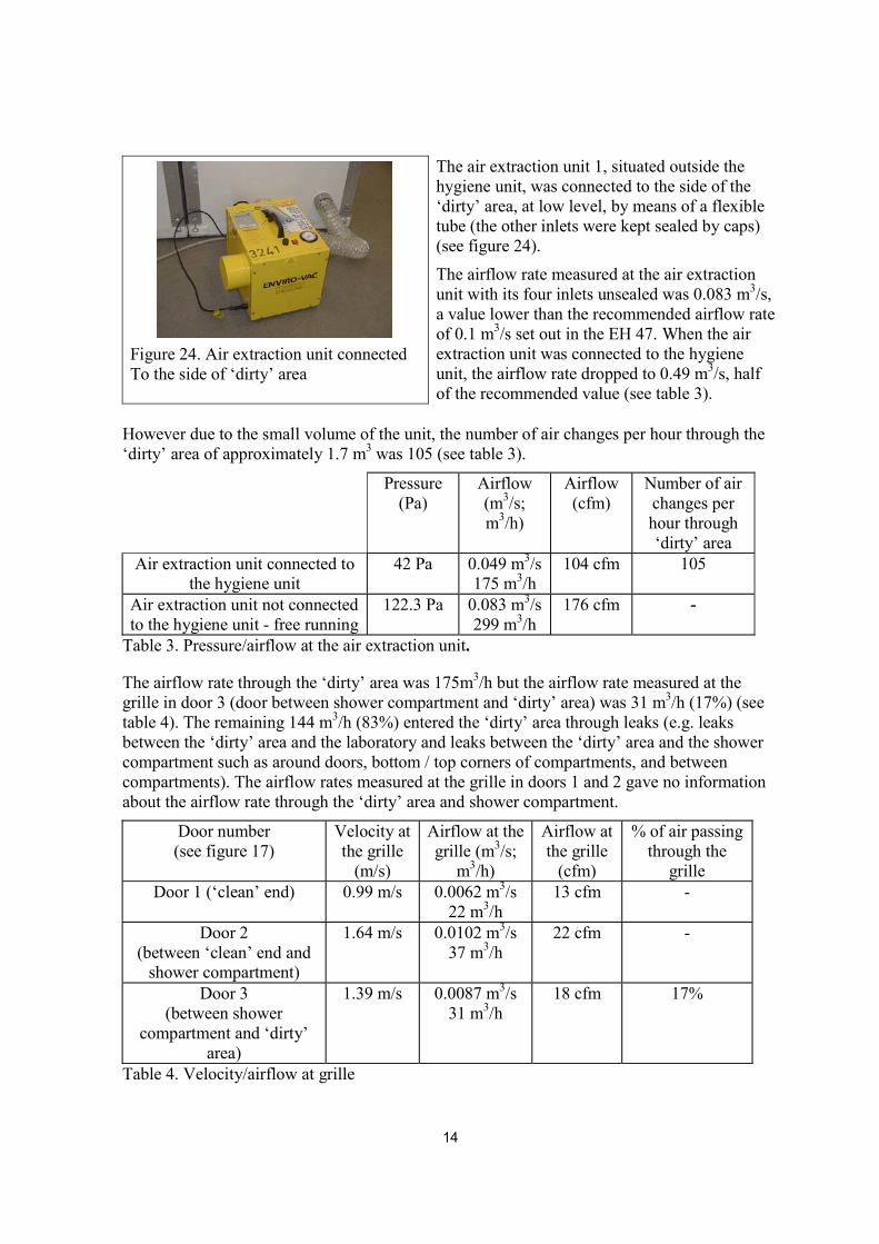
Figure 24. Air extraction unit connected To the side of ‘dirty’ area
The air extraction unit 1, situated outside the hygiene unit, was connected to the side of the ‘dirty’ area, at low level, by means of a flexible tube (the other inlets were kept sealed by caps) (see figure 24). The airflow rate measured at the air extraction unit with its four inlets unsealed was 0.083 m3/s, a value lower than the recommended airflow rate of 0.1 m3/s set out in the EH 47. When the air extraction unit was connected to the hygiene unit, the airflow rate dropped to 0.49 m3/s, half of the recommended value (see table 3).
However due to the small volume of the unit, the number of air changes per hour through the ‘dirty’ area of approximately 1.7 m3 was 105 (see table 3).
Pressure (Pa)
Airflow (m3/s; m3/h)
Airflow (cfm)
Number of air changes per hour through ‘dirty’ area
Air extraction unit connected to the hygiene unit
42 Pa 0.049 m3/s 175 m3/h
104 cfm 105
Air extraction unit not connected to the hygiene unit - free running
122.3 Pa 0.083 m3/s 299 m3/h
176 cfm -
Table 3. Pressure/airflow at the air extraction unit.
The airflow rate through the ‘dirty’ area was 175m3/h but the airflow rate measured at the grille in door 3 (door between shower compartment and ‘dirty’ area) was 31 m3/h (17%) (see table 4). The remaining 144 m3/h (83%) entered the ‘dirty’ area through leaks (e.g. leaks between the ‘dirty’ area and the laboratory and leaks between the ‘dirty’ area and the shower compartment such as around doors, bottom / top corners of compartments, and between compartments). The airflow rates measured at the grille in doors 1 and 2 gave no information about the airflow rate through the ‘dirty’ area and shower compartment.
Door number (see figure 17)
Velocity at the grille
(m/s)
Airflow at the grille (m3/s;
m3/h)
Airflow at the grille
(cfm)
% of air passing through the
grille Door 1 (‘clean’ end) 0.99 m/s
0.0062 m3/s
22 m3/h 13 cfm -
Door 2 (between ‘clean’ end and
shower compartment)
1.64 m/s
0.0102 m3/s 37 m3/h
22 cfm -
Door 3 (between shower
compartment and ‘dirty’ area)
1.39 m/s
0.0087 m3/s 31 m3/h
18 cfm 17%
Table 4. Velocity/airflow at grille
15
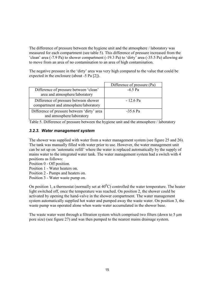
The difference of pressure between the hygiene unit and the atmosphere / laboratory was measured for each compartment (see table 5). This difference of pressure increased from the ‘clean’ area (-7.9 Pa) to shower compartment (-19.3 Pa) to ‘dirty’ area (-35.5 Pa) allowing air to move from an area of no contamination to an area of high contamination.
The negative pressure in the ‘dirty’ area was very high compared to the value that could be expected in the enclosure (about -5 Pa [2]).
Difference of pressure (Pa) Difference of pressure between ‘clean’
area and atmosphere/laboratory -4.5 Pa
Difference of pressure between shower
compartment and atmosphere/laboratory - 12.6 Pa
Difference of pressure between ‘dirty’ area and atmosphere/laboratory
-35.6 Pa
Table 5. Difference of pressure between the hygiene unit and the atmosphere / laboratory
3.2.3. Water management system The shower was supplied with water from a water management system (see figure 25 and 26). The tank was manually filled with water prior to use. However, the water management unit can be set up on ‘automatic refill’ where the water is replaced automatically by the supply of mains water to the integrated water tank. The water management system had a switch with 4 positions as follows: Position 0 - Off position. Position 1 - Water heaters on. Position 2 - Pumps and heaters on. Position 3 - Water waste pump on.
On position 1, a thermostat (normally set at 400C) controlled the water temperature. The heater light switched off, once the temperature was reached. On position 2, the shower could be activated by opening the hand-valve in the shower compartment. The water management system automatically supplied hot water and pumped away the waste water. On position 3, the waste pump was operated alone when waste water accumulated in the shower base.
The waste water went through a filtration system which comprised two filters (down to 5 �m pore size) (see figure 27) and was then pumped to the nearest mains drainage system.
16
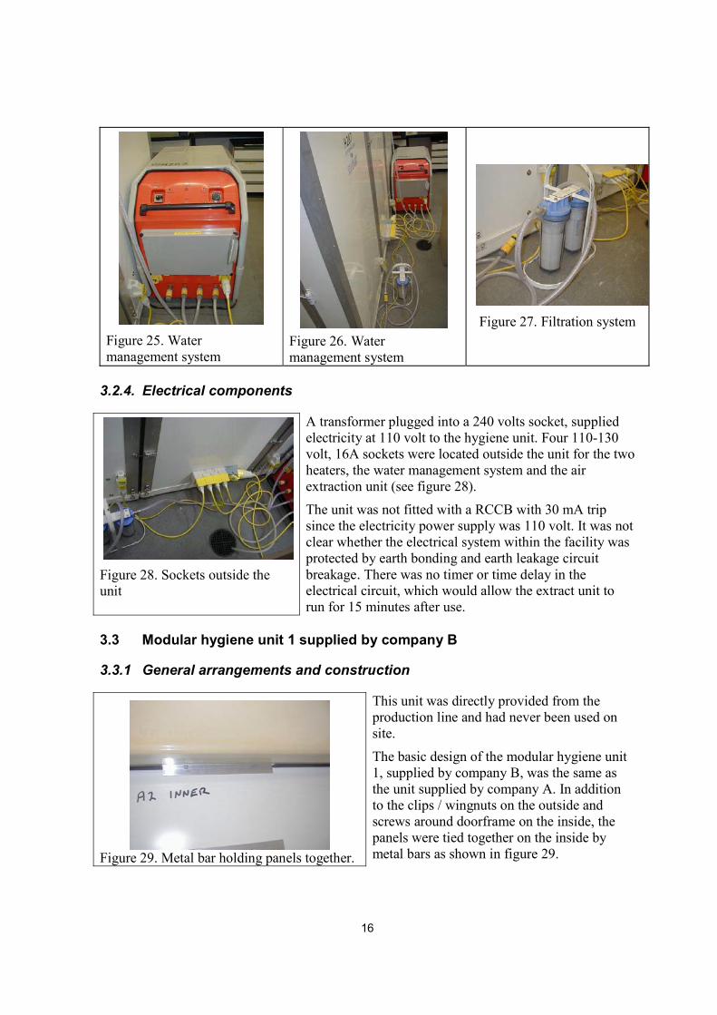
Figure 25. Water management system
Figure 26. Water management system
Figure 27. Filtration system
3.2.4. Electrical components
Figure 28. Sockets outside the unit
A transformer plugged into a 240 volts socket, supplied electricity at 110 volt to the hygiene unit. Four 110-130 volt, 16A sockets were located outside the unit for the two heaters, the water management system and the air extraction unit (see figure 28). The unit was not fitted with a RCCB with 30 mA trip since the electricity power supply was 110 volt. It was not clear whether the electrical system within the facility was protected by earth bonding and earth leakage circuit breakage. There was no timer or time delay in the electrical circuit, which would allow the extract unit to run for 15 minutes after use.
3.3 Modular hygiene unit 1 supplied by company B
3.3.1 General arrangements and construction
Figure 29. Metal bar holding panels together.
This unit was directly provided from the production line and had never been used on site. The basic design of the modular hygiene unit 1, supplied by company B, was the same as the unit supplied by company A. In addition to the clips / wingnuts on the outside and screws around doorframe on the inside, the panels were tied together on the inside by metal bars as shown in figure 29.
17
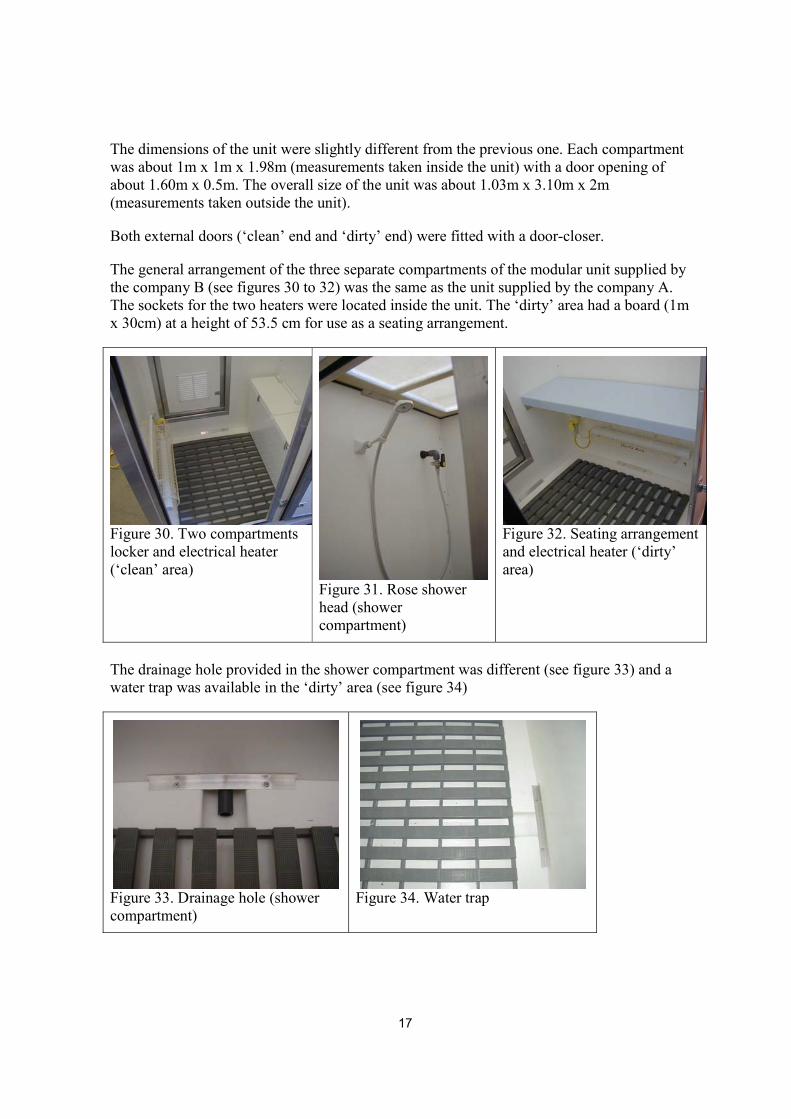
The dimensions of the unit were slightly different from the previous one. Each compartment was about 1m x 1m x 1.98m (measurements taken inside the unit) with a door opening of about 1.60m x 0.5m. The overall size of the unit was about 1.03m x 3.10m x 2m (measurements taken outside the unit).
Both external doors (‘clean’ end and ‘dirty’ end) were fitted with a door-closer.
The general arrangement of the three separate compartments of the modular unit supplied by the company B (see figures 30 to 32) was the same as the unit supplied by the company A. The sockets for the two heaters were located inside the unit. The ‘dirty’ area had a board (1m x 30cm) at a height of 53.5 cm for use as a seating arrangement.
Figure 30. Two compartments locker and electrical heater (‘clean’ area)
Figure 31. Rose shower head (shower compartment)
Figure 32. Seating arrangement and electrical heater (‘dirty’ area)
The drainage hole provided in the shower compartment was different (see figure 33) and a water trap was available in the ‘dirty’ area (see figure 34)
Figure 33. Drainage hole (shower compartment)
Figure 34. Water trap
18
3.3.2. Extract ventilation
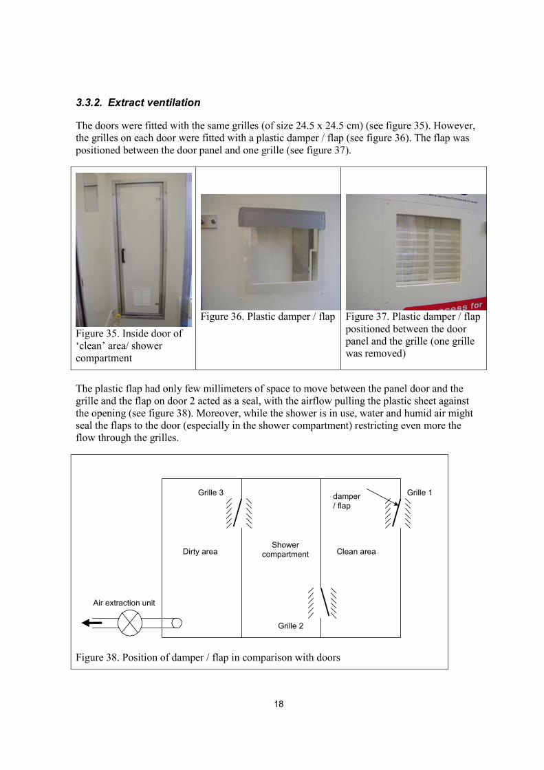
The doors were fitted with the same grilles (of size 24.5 x 24.5 cm) (see figure 35). However, the grilles on each door were fitted with a plastic damper / flap (see figure 36). The flap was positioned between the door panel and one grille (see figure 37).
Figure 35. Inside door of ‘clean’ area/ shower compartment
Figure 36. Plastic damper / flap
Figure 37. Plastic damper / flap positioned between the door panel and the grille (one grille was removed)
The plastic flap had only few millimeters of space to move between the panel door and the grille and the flap on door 2 acted as a seal, with the airflow pulling the plastic sheet against the opening (see figure 38). Moreover, while the shower is in use, water and humid air might seal the flaps to the door (especially in the shower compartment) restricting even more the flow through the grilles.
Dirty area Clean areaShower
compartment
Grille 1
Grille 2
Grille 3 damper/ flap
Air extraction unit
Figure 38. Position of damper / flap in comparison with doors

19
Figure 39. Air extraction unit connected to the side of ‘dirty’ area
The air extraction unit 2 was connected to the side of the ‘dirty’ area at low level, by means of a flexible tube (see figure 39). As installed in the laboratory, the flexible tubing (150mm diameter) was connected to the outlet spigot (110 mm) of the hygiene unit with duct tape. As the joint leaked badly, the flexible tubing was removed and an adapter was fitted.
The airflow rate measured at the air extraction unit was 0.088m3/s. When the air extraction unit was connected to the hygiene unit, the airflow dropped to 0.054m3/s (hygiene unit without dampers / flaps) and 0.048 m3/s (hygiene unit fitted with dampers / flaps) (see table 6).
The number of air changes per hour expected through the ‘dirty’ area of approximately 2 m3 was 97 (see table 6).
Airflow (m3/s; m3/h)
Airflow (cfm)
Number of air changes per hour
through the ‘dirty’ area
Air extraction unit connected to the hygiene unit (with dampers / flaps fitted)
0.048 m3/s 174 m3/h
102 cfm
87
Air extraction unit connected to the hygiene unit (without dampers / flaps fitted)
0.054 m3/s 195 m3/h
115 cfm
97
Air extraction unit not connected to the hygiene unit -free running
0.088 m3/s 318 m3/h
187 cfm
-
Table 6. Pressure / airflow at the air extraction unit
The airflow rate through the ‘dirty’ area (hygiene unit without dampers / flaps) was 195m3/h but the airflow rate measured at the grille in door 3 (door between shower compartment and ‘dirty’ area) was 92 m3/h (47%) (see table 4). The remaining 103 m3/h (53%) entered the ‘dirty’ area through leaks.
The airflow rate through the ‘dirty’ area (hygiene unit with dampers / flaps) was 174m3/h but the airflow rate measured at the grille in door 3 (door between shower compartment and ‘dirty’ area) was 36 m3/h (21%) (see table 4). The remaining 138 m3/h (79%) entered the ‘dirty’ area through leaks. The airflow rate at the grilles on door 1 and 2 decreased dramatically (ten times less) in comparison with the values measured while the hygiene unit was not fitted with plastic dampers. These low values (about 0.002 m3/s or 4cfm) demonstrated the seal effect of the plastic damper / flap on door 2 (door between ‘clean’ end and shower compartment). The plastic flaps forced the air to enter by the doors and gaps between panels.
20
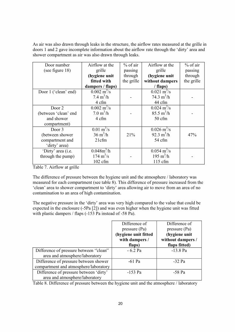
As air was also drawn through leaks in the structure, the airflow rates measured at the grille in doors 1 and 2 gave incomplete information about the airflow rate through the ‘dirty’ area and shower compartment as air was also drawn through leaks.
Door number (see figure 18)
Airflow at the grille
(hygiene unit fitted with
dampers / flaps)
% of air passing through the grille
Airflow at the grille
(hygiene unit without dampers
/ flaps)
% of air passing through the grille
Door 1 (‘clean’ end) 0.002 m3/s 7.4 m3/h
4 cfm
-
0.021 m3/s 74.3 m3/h
44 cfm
-
Door 2 (between ‘clean’ end
and shower compartment)
0.002 m3/s 7.0 m3/h
4 cfm
-
0.024 m3/s 85.5 m3/h
50 cfm
-
Door 3 (between shower compartment and
‘dirty’ area)
0.01 m3/s 36 m3/h 21cfm
21%
0.026 m3/s 92.3 m3/h
54 cfm
47%
‘Dirty’ area (i.e. through the pump)
0.048m3/h 174 m3/s 102 cfm
-
0.054 m3/s 195 m3/h 115 cfm
-
Table 7. Airflow at grille
The difference of pressure between the hygiene unit and the atmosphere / laboratory was measured for each compartment (see table 8). This difference of pressure increased from the ‘clean’ area to shower compartment to ‘dirty’ area allowing air to move from an area of no contamination to an area of high contamination.
The negative pressure in the ‘dirty’ area was very high compared to the value that could be expected in the enclosure (-5Pa [2]) and was even higher when the hygiene unit was fitted with plastic dampers / flaps (-153 Pa instead of -58 Pa).
Difference of pressure (Pa)
(hygiene unit fitted with dampers /
flaps)
Difference of pressure (Pa) (hygiene unit
without dampers / flaps fitted)
Difference of pressure between ‘'clean'’ area and atmosphere/laboratory
- 6.2 Pa
-13.8 Pa
Difference of pressure between shower compartment and atmosphere/laboratory
-61 Pa -32 Pa
Difference of pressure between ‘dirty’ area and atmosphere/laboratory
-153 Pa -58 Pa
Table 8. Difference of pressure between the hygiene unit and the atmosphere / laboratory

21
3.3.3. Water management system / electrical components
The water management system and electrical arrangement were the same as those provided on the modular hygiene unit 1 supplied by the company A.
3.4. Modular hygiene unit 2 3.4.1. General arrangements and construction � Basic design of hygiene unit
The hygiene unit (see figures 40 and 41) was constructed of 10 plastic panels sliding one into each other and 6 ‘plastic units’ (for floor and roof). Partition walls between ‘dirty’ area/shower compartment and shower compartment/’clean’ area were single shared panels.
Figure 40. General view of modular hygiene unit
Figure 41. General view of hygiene unit 2
The unit comprised three separate compartments (‘dirty’ area, shower compartment and ‘clean’ area) and access between them was by non-self-closing doors with ventilation grilles. Each compartment was about 0.95m x 1.53m x 1.90-2.06m (measurements taken inside the unit) with door openings of about 1.51m x 0.52m (see figure 42). The overall size of the unit was about 3m x 1.5m x 2.10m (measurements taken outside the unit).
Each door was held closed by mean of two latches and a rubber seal. The ‘dirty’ area and ‘clean’ area were provided with outward opening, non-self closing doors. The inside doors between the separate compartments opened towards the shower compartment (see figures 43 and 44). The doors had a poor fit and the latches closed with difficulty. External doors were clearly marked “Clean” and “Dirty” and had an “Entry Prohibited” graphic. In the shower compartment, doors were marked “Clean” and “Dirty”.

22
Clean area Shower compartment Dirty area
0.95m
1.53m
1.90
-2.0
6m
0.52m
1.51
m
air extraction unit8.5cm of diameter
grille
Figure 42. Dimensions of the modular hygiene unit 2 (measurements taken inside the unit)
Figure 43. Door access between two compartments.
Figure 44. Non-self-closing door.
The hygiene unit had its own ventilation, showering, heating and water filtration systems.
� Three compartment hygiene unit
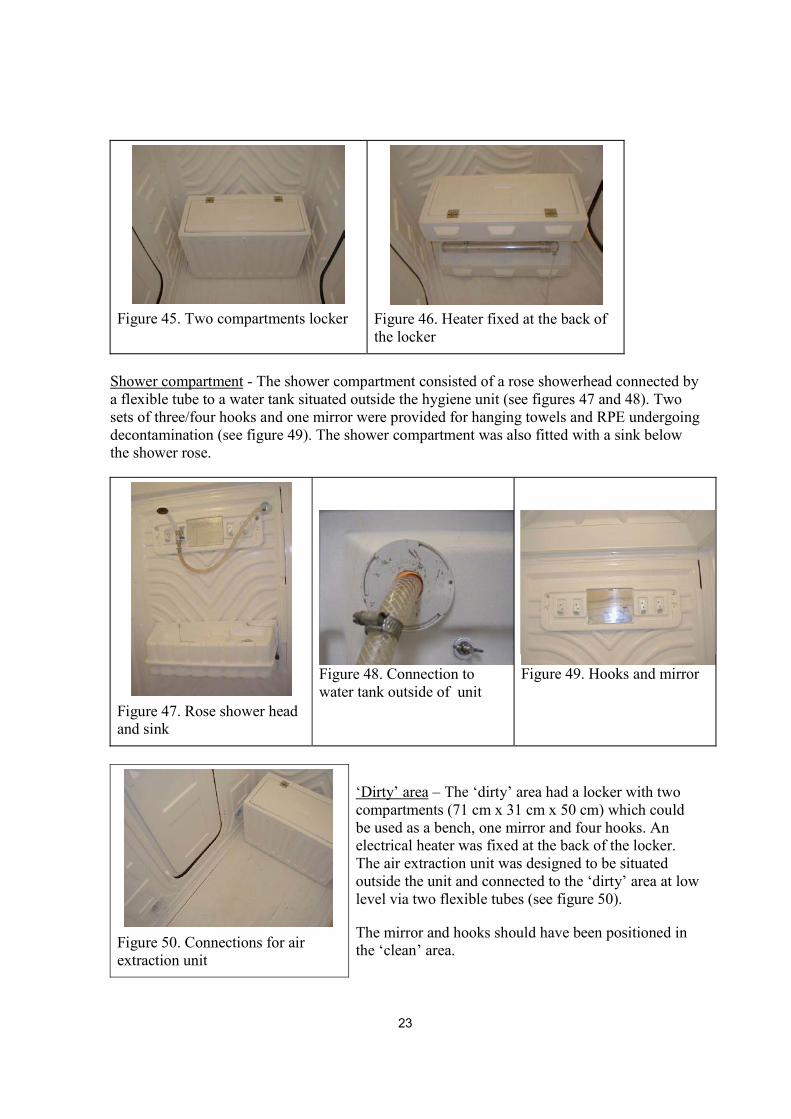
‘Clean’ area - The ‘clean’ area had a two compartments locker (71 cm x 31 x 50 cm) which could be used as a bench (see figure 45). Heating is supplied by an electrical heater fixed at the back of the locker (see figure 46). There was no mirror or hook.
23
Figure 45. Two compartments locker
Figure 46. Heater fixed at the back of the locker
Shower compartment - The shower compartment consisted of a rose showerhead connected by a flexible tube to a water tank situated outside the hygiene unit (see figures 47 and 48). Two sets of three/four hooks and one mirror were provided for hanging towels and RPE undergoing decontamination (see figure 49). The shower compartment was also fitted with a sink below the shower rose.
Figure 47. Rose shower head and sink
Figure 48. Connection to water tank outside of unit
Figure 49. Hooks and mirror
Figure 50. Connections for air extraction unit
‘Dirty’ area – The ‘dirty’ area had a locker with two compartments (71 cm x 31 cm x 50 cm) which could be used as a bench, one mirror and four hooks. An electrical heater was fixed at the back of the locker. The air extraction unit was designed to be situated outside the unit and connected to the ‘dirty’ area at low level via two flexible tubes (see figure 50).
The mirror and hooks should have been positioned in the ‘clean’ area.

24
The general arrangement of the three compartments is summarized in the figure below (see figure 51).
Light
Seat/locker Heater Hooks Mirror Shower roseHooks Sink Heater
Seat/locker
LightsHooks Mirror Hooks Mirror Hooks
DIRTY AREA CLEAN AREASHOWER COMPARTMENT
Figure 51. General arrangement of the modular hygiene unit 2
� Construction
Internal walls, floors and ceilings were constructed of impervious materials. A drainage hole was provided in the shower compartment (see figure 52). However, no drainage hole was supplied in the ‘dirty’ and ‘clean’ areas.
Lighting was provided throughout the unit (see figure 53).
Figure 52. Draining hole – Shower compartment
Figure 53. Light
Compartment Intensity (Lux) ‘Clean’ area 180 Lux Shower area 210 Lux ‘Dirty’ area 350 Lux
The lighting level in each compartment (see table 9) were adequate compared with recommended lighting levels of 100-150 for circulation areas/entrances, lobbies, waiting areas and 300-500 for factories [3].
Table 9. Light intensity measured in each compartment

25
�
� Potential dust trap
Dust might be trapped: - in gaps between the light fittings and the ceiling; - in gaps behind mirrors/hook holders; - in the compartment locker placed in the ‘dirty’ area; - inside the shower sink (the sink had two evacuation holes which were not directly
connected via tubes to the two holes underneath the sink). 3.4.2 Extract ventilation
A system of two grilles with self-closing flaps was provided allowing a diagonal ventilation of the unit. The grilles were positioned on each side of the doors between compartments and of the outside door to the ‘clean’ area (see figure 42 and 54). Each grille, of 13 x 12cm size, consisted of four flaps leaving a diameter of 8.5 cm on the extract side (see figures 54 to 56).
Figure 54. Outside door of ‘clean’ area (grilles located left-hand and right-hand top of panel)
Figure 55. Grille - extract side
Figure 56. Grille - ventilation side
Figure 57. Connections between air extraction and hygiene unit
The air extraction unit 1 was connected to the ‘dirty’ area of the hygiene unit, at low level, by the means of two flexible tubes (the other inlets were kept seal by caps) (see figure 57). The tubes were fitted in two holes of diameter 8.5 cm, on each side of the outside door.
The airflow rate measured at the air extraction unit with its four inlets unsealed was 0.083 m3/s. When the air extraction unit was connected to the hygiene unit, the airflow dropped to 0.067 m3/s (see table 10).

26
The number of air changes per hour through the ‘dirty’ area of approximately 3m3 was 81 (see table 10).
Pressure (Pa)
Airflow (m3/s)
Airflow (cfm)
Number of air changes per hour through ‘dirty’ area
Air extraction unit connected to the hygiene unit
79.4 Pa 0.067 m3/s 241 m3/h
142 cfm 81
Air extraction unit not connected to the hygiene unit
- free running
122.3 Pa 0.083 m3/s 299 m3/h
176 cfm _
Table 10. Pressure/airflow at the air extraction unit
The airflow rate through the ‘dirty’ area was 241m3/h but the airflow rate measured at the grilles in door between shower compartment and ‘dirty’ area was 106 m3/h (44%) (see table 11). The remaining 135 m3/h (56%) entered the ‘dirty’ area through leaks.
The airflow rates measured at the grille in doors 1 and 2 gave no information about the airflow rate through the ‘dirty’ area and shower compartment as air was also drawn through leaks.
Grilles/air extraction
ports position
Point of measurement
Velocity at grilles
(m/s)
Airflow at grilles (m3/s; m3/h)
Total airflow at
grilles (m3/s; m3/h)
Total airflow at
grilles (cfm)
% of air passing through grilles
‘Clean’ end
Right grille
left grille
0.94 m/s
0.89 m/s
0.0059 m3/s (21m3/h)
0.0056 m3/s (20m3/h)
0.0115 m3/s
41 m3/h
24cfm
-
Between ‘clean’
and shower
area
Right grille
left grille
1.29 m/s
0.99 m/s
0.0081 m3/s (29m3/h)
0.0062 m3/s (22m3/h)
0.0143 m3/s
51 m3/h
30cfm
-
Between shower
and ‘dirty’ area
Right grille
left grille
2.34 m/s
2.34 m/s
0.0146 m3/s (53m3/h)
0.0146 m3/s (53 m3/h)
0.0292 m3/s
106 m3/h
62cfm
44%
‘Dirty’
end
Right air extraction port
left air
extraction port
6.27 m/s
4.18 m/s
0.0392 m3/s
0.027 m3/s
0.062 m3/s 238 m3/h
131cfm
_
Table 11. Velocity/airflow at grille

27
The difference of pressure between the hygiene unit and the atmosphere in the laboratory was measured for each compartment (see table 12). This difference of pressure increased from the ‘clean’ area (-7.9 Pa) to shower compartment (-19.3 Pa) to ‘dirty’ area (-35.5 Pa) allowing air to move from an area of no contamination to an area of high contamination.
As with the modular hygiene unit 1, the negative pressure in the ‘dirty’ area was very high compared to the value that could be expected in the enclosure (about -5 Pa [2]).
Difference of pressure (Pa) Difference of pressure between ‘clean’
area and atmosphere/laboratory -7.9 Pa
Difference of pressure between shower
compartment and atmosphere/laboratory -19.3 Pa
Difference of pressure between ‘dirty’ area and atmosphere/laboratory
-35.3 Pa
Table 12. Difference of pressure between the hygiene unit and the atmosphere / laboratory
3.4.3. Water management The shower was supplied with water from a water management system, manually filled prior to use (see figure 58). The water temperature was controlled by a thermostat, which was normally set at 400C.
The waste water went through a filtration system which comprised two filters (down to 5 �m pore size) (see figure 59) and then sent to the nearest drainage system. However, it should be noted that after a shower, waste water accumulated in the drainage hole of the shower compartment.
Figure 58. Water management system
Figure 59. Water management system showing filtration system

28
3.4.4. Electrical components
Figure 60. Eight sockets distribution box
A transformer plugged into a 240 volt socket, supplied electricity at 110 volt to the two heaters, the air extraction unit and water management system by means of an eight sockets distribution box (see figure 60). The unit was not fitted with a RCCB with 30 mA trip since the electricity power supply was 110 volt.
Each heater (in ‘clean’ and ‘dirty’ areas) was plugged in the socket’s distribution box located outsides the hygiene unit. The hole where the heater cable passed through was taped over from the inside of the unit (see figures 61 and 62).
Figure 61. Heater plugged in a socket located inside the unit
Figure 62. Connection from heater socket to distribution box (photo taken outside the unit)
3.5. Modular hygiene unit 3 (a unit used for transit facilities)
The hygiene unit 3 was a modular hygiene unit used as transit facilities. The unit did not have an outlet spigot and could not be connected to an air extraction unit.
� Basic design of hygiene unit
The hygiene unit (see figures 63 and 64) was constructed of 10 plastic panels sliding one into each other and 6 ‘plastic units’ (for floor and roof). Partition walls between ‘dirty’ area/shower compartment and shower compartment/’clean’ area were single shared panels.

29
Figure 63. General view of the transit unit
Figure 64. General view of the transit unit
The unit comprised three separate compartments and access between them was by self-closing doors. Each compartment was about 0.96-1m x 0.95-0.98m x 1.98m (measurements taken inside the unit) with door opening of about 1.55m x 0.55m (see figure 65). The overall size of the unit was about 3.10m x 0.96m x 2m (measurements taken outside the unit).
0.96-1 m
0.95-0.98m
grille
1.98
m
1.53
m
0.55m
Shower compartment
Figure 65. Dimensions of the hygiene unit 3 (measurements taken inside the unit)
The doors were held closed by magnets stuck to the frames and doors (see figure 71). The external doors were provided with outward opening, self closing doors. The inside doors between the separate compartments opened towards the shower compartment.
All four doors were fitted with grilles (see figures 71 to 73). Each grille had a size of 24cm x 8.5cm with eight slits of 1cm x 6.2 cm and two of 1cm x 4.3cm. On each doors, two grilles were fitted on each side of the panel over a window, allowing dust to be trapped inside. However, the grilles could be closed.

30
Figure 71. Inside door
Figure 72. Inside door
Figure 73. Grille
Internal walls were constructed of impervious materials providing a smooth surface. A plastic mat was placed in each compartment (see figure 74). There was no light fitted through the facility but the transparent ceiling allowed light to come in the hygiene unit (figure 75).
The compartments were unfurnished and only the shower compartment was supplied with a rose shower-head connected by a flexible tube to a water management system situated outside the hygiene unit (see figure 76). A drainage hole was provided in the shower compartment (see figure 77).
Figure 74. Floor
Figure 75. Ceiling
Figure 76. Rose shower head - Shower compartment
Figure 77. Drainage hole – Shower compartment

31
The general arrangement of the hygiene unit is summarised in the figure below (see figure 78).
Shower rose
SHOWER COMPARTMENT
Figure 78. General arrangement of the modular hygiene unit 3
4. SITE VISITS
Two visits were organized to assess modular hygiene units (units 2 and 4 on-hire from the company A) in operation on asbestos removal sites.
4.1. Moor House site visit of the modular hygiene unit 4 4.1.1. The site
Figure 79. Modular hygiene unit 4 connected to an asbestos enclosure
A visit to a building (Moor House, London Wall, London EC2) was organized to look at the modular hygiene unit 4 in operation on an asbestos removal site (see figure 79). On site, there were two modular hygiene units; one was in use while the other had just been set up.
The modular hygiene units were attached to the asbestos removal site via an intervening space.
The modular hygiene unit 4 was a larger model of the modular hygiene unit 2 with the same design and arrangement. The ‘clean’ and ‘dirty’ areas was approximately 1.5m x 1.5m x 2m and the shower compartment was 1m x 1.5m x 2m. The ‘dirty’ and ‘clean’ areas had enough space for the fitting of two storage lockers instead of one.

32
4.1.2 General observations � Inside view of the modular hygiene unit 4
As observed for the hygiene unit 2, the doors on the hygiene unit 4 had a bad fitting design and were difficult to close properly. These doors needed to be pushed hard. When entering the hygiene unit, the two inside doors between compartments were left open.
‘Clean’ area
Five asbestos removal workers used the hygiene unit. Personal clothing and clean shoes/boots were left in the ‘clean’ area (see figures 80 and 81). A rug was placed on the floor for workers coming out of the shower, as the floor might be slippery (see figure 81). It should be noted that unlike the hygiene unit 2, set up in HSL laboratory, a mirror was provided in the hygiene unit 4 to help workers to obtain a good face fit of RPE.
The two storage lockers were positioned next to each other on the longside of the ‘clean’ area as shown in figure 82, blocking one of the ventilation grille.
Figure 80. Inside view of ‘clean’ area
Figure 81. Inside view of ‘clean’ area
Figure 82. Lockers blocking one of the grille ventilation
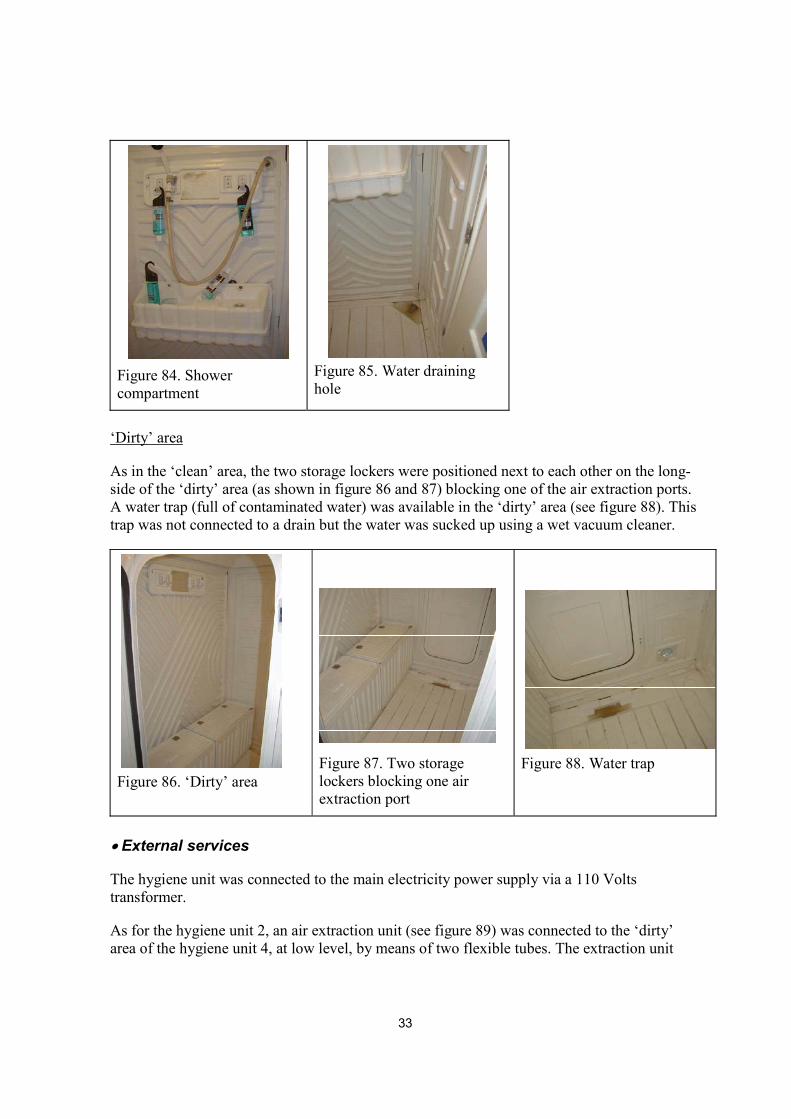
Shower compartment
Soaps, shampoos and nailbrush were hung on hooks or placed on the sink for easy accessibility (see figure 84). Contaminated water was trapped in the draining hole (see figure 85).
33
Figure 84. Shower compartment
Figure 85. Water draining hole
‘Dirty’ area
As in the ‘clean’ area, the two storage lockers were positioned next to each other on the long-side of the ‘dirty’ area (as shown in figure 86 and 87) blocking one of the air extraction ports. A water trap (full of contaminated water) was available in the ‘dirty’ area (see figure 88). This trap was not connected to a drain but the water was sucked up using a wet vacuum cleaner.
Figure 86. ‘Dirty’ area
Figure 87. Two storage lockers blocking one air extraction port
Figure 88. Water trap
�
� External services
The hygiene unit was connected to the main electricity power supply via a 110 Volts transformer.
As for the hygiene unit 2, an air extraction unit (see figure 89) was connected to the ‘dirty’ area of the hygiene unit 4, at low level, by means of two flexible tubes. The extraction unit

34
was not interconnected with the electrical light supply and did not operate for 15 minutes after lights were switched off.
The shower was supplied with warm water from the same water management system described in paragraph 3.2.3 (see figure 90). However, this water management system was connected to the 240 Volts main electricity supply and was fitted with a RCCB.
The contaminated water went through a filtration system.
Figure 89. Air extraction unit
Figure 90. Water management system
�
� Positioning of the DCU
The hygiene unit was connected to the enclosure by means of an intervening space. The polythene sheeting materials from the intervening space was taped around the ‘dirty’ area door (see figure 91). The two flexible tubes from the air extraction unit were fitted in two ports of diameter 8.5cm, on each side of the ‘dirty’ area outside door (see figures 92 and 93). One flexible tube remained outside (as shown in figure 92) the intervening space while the other went through the sheeting material (as shown in figure 93).
Figure 91. Hygiene unit attached to intervening space.
Figure 92. Flexible tube connecting the air extraction unit to hygiene unit
Figure 93. Flexible tube connecting the air extraction unit to hygiene unit
35
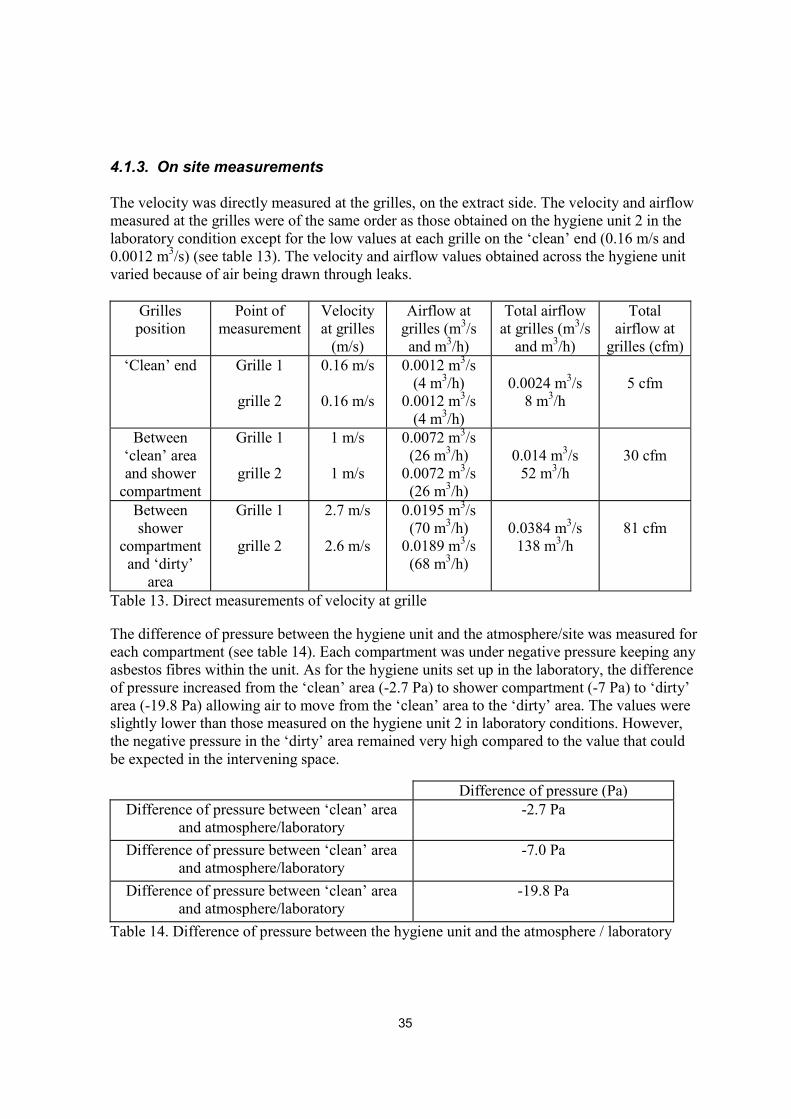
4.1.3. On site measurements The velocity was directly measured at the grilles, on the extract side. The velocity and airflow measured at the grilles were of the same order as those obtained on the hygiene unit 2 in the laboratory condition except for the low values at each grille on the ‘clean’ end (0.16 m/s and 0.0012 m3/s) (see table 13). The velocity and airflow values obtained across the hygiene unit varied because of air being drawn through leaks.
Grilles position
Point of measurement
Velocity at grilles
(m/s)
Airflow at grilles (m3/s and m3/h)
Total airflow at grilles (m3/s
and m3/h)
Total airflow at
grilles (cfm)‘Clean’ end Grille 1
grille 2
0.16 m/s
0.16 m/s
0.0012 m3/s (4 m3/h)
0.0012 m3/s (4 m3/h)
0.0024 m3/s
8 m3/h
5 cfm
Between ‘clean’ area and shower
compartment
Grille 1
grille 2
1 m/s
1 m/s
0.0072 m3/s (26 m3/h)
0.0072 m3/s (26 m3/h)
0.014 m3/s
52 m3/h
30 cfm
Between shower
compartment and ‘dirty’
area
Grille 1
grille 2
2.7 m/s
2.6 m/s
0.0195 m3/s (70 m3/h)
0.0189 m3/s (68 m3/h)
0.0384 m3/s
138 m3/h
81 cfm
Table 13. Direct measurements of velocity at grille
The difference of pressure between the hygiene unit and the atmosphere/site was measured for each compartment (see table 14). Each compartment was under negative pressure keeping any asbestos fibres within the unit. As for the hygiene units set up in the laboratory, the difference of pressure increased from the ‘clean’ area (-2.7 Pa) to shower compartment (-7 Pa) to ‘dirty’ area (-19.8 Pa) allowing air to move from the ‘clean’ area to the ‘dirty’ area. The values were slightly lower than those measured on the hygiene unit 2 in laboratory conditions. However, the negative pressure in the ‘dirty’ area remained very high compared to the value that could be expected in the intervening space.
Difference of pressure (Pa) Difference of pressure between ‘clean’ area
and atmosphere/laboratory -2.7 Pa
Difference of pressure between ‘clean’ area
and atmosphere/laboratory -7.0 Pa
Difference of pressure between ‘clean’ area and atmosphere/laboratory
-19.8 Pa
Table 14. Difference of pressure between the hygiene unit and the atmosphere / laboratory
36
4.2. Barrow site visit of the modular hygiene unit 2 4.2.1 The site
Figure 94. Hygiene unit 2 connected to an asbestos enclosure
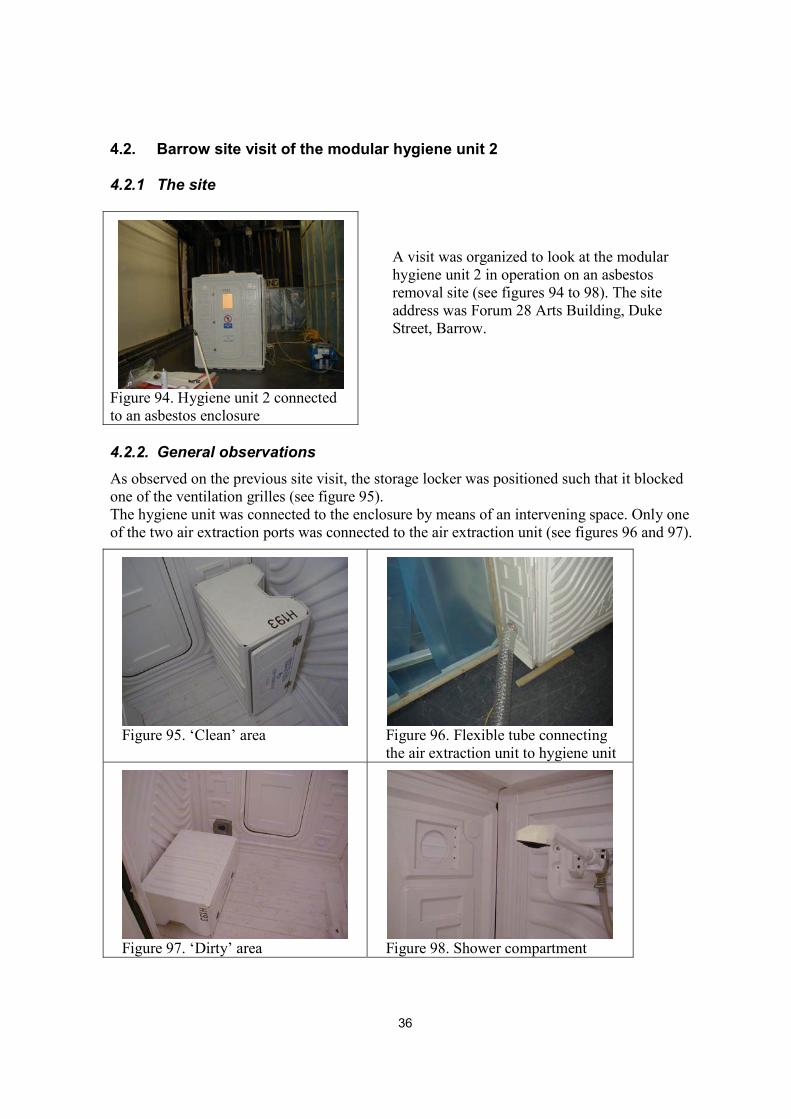
A visit was organized to look at the modular hygiene unit 2 in operation on an asbestos removal site (see figures 94 to 98). The site address was Forum 28 Arts Building, Duke Street, Barrow.
4.2.2. General observations As observed on the previous site visit, the storage locker was positioned such that it blocked one of the ventilation grilles (see figure 95). The hygiene unit was connected to the enclosure by means of an intervening space. Only one of the two air extraction ports was connected to the air extraction unit (see figures 96 and 97).
Figure 95. ‘Clean’ area
Figure 96. Flexible tube connecting the air extraction unit to hygiene unit
Figure 97. ‘Dirty’ area
Figure 98. Shower compartment

37
5. DISCUSSION AND CONCLUSION Size of modular hygiene units To enable satisfactory showering and decontamination, each compartment should have dimensions at least 1m x 1m x 2m (height). If more than a couple of workers are using the facility and all have to leave their clothes and other items in the unit, then it should be at least 1m x 1.5m x 2m (height).
A summary table of typical dimensions of modular hygiene units is presented below.
Modular hygiene unit 1 supplied by company A
Modular hygiene unit 1 supplied by company B
Modular hygiene unit 2
Modular hygiene unit 4
Modular hygiene unit 3 (transit unit)
Dimensions
‘clean’ / ‘dirty’ / shower areas: 1 x 0.8 x 2m
‘clean’ / ‘dirty’ / shower areas:
1 x 1 x 2m
‘clean’ / ‘dirty’ / shower areas:
1 x 1.5 x 2m
‘clean’ / ‘dirty’ areas: 1.5 x 1.5
x 2m shower: 1 x 1.5
x 2m
‘clean’ / ‘dirty’ /
shower areas: 1 x 1 x 2m
Table 15. Typical dimensions of modular contamination units Construction and layout of modular hygiene units In general, the layout and provision (e.g. cupboards, seats, hooks, mirrors, etc) of modular hygiene units were fairly good. Only the shower compartment of one unit did not have suitable provision (e.g. hooks, sinks), for hanging towels, RPE and holding shampoo, nail brush, soap, etc. The units were constructed of impervious materials providing a smooth surface and seemed fairly robust. However, the clips and wingnuts, which fastened panels together might be damaged after time, especially during transportation. In such cases, care should be taken to check and ensure that the roof units are tightly engaged and there are no gaps, which could give rise to leaks. On the unit 1 supplied by the company B, the panels were also tied together on the inside by additional metals bars.
The non-self closing doors, fitted with latches, were difficult to close and might be left opened on asbestos removal site, increasing the risks of contamination of the ‘clean’ area with asbestos.
On site, workers placed storage lockers, which had no designated attached positions in units, close to the air extraction ports or ventilation grilles, reducing the airflow movement and efficiency through the unit. Lockers should have a designated position in the unit and be fixed in place.
The hygiene units providing storage lockers, as a seating arrangement, in the dirty area could become easily contaminated, difficult to clean and should be avoided. Also, the sink did not have a separate drainage system or water supply. It was also of a design that would be difficult to clean as it contained spaces, which were difficult to access. The sink should be fitted with a drainage pipe and the storage locker replaced by a bench.
38
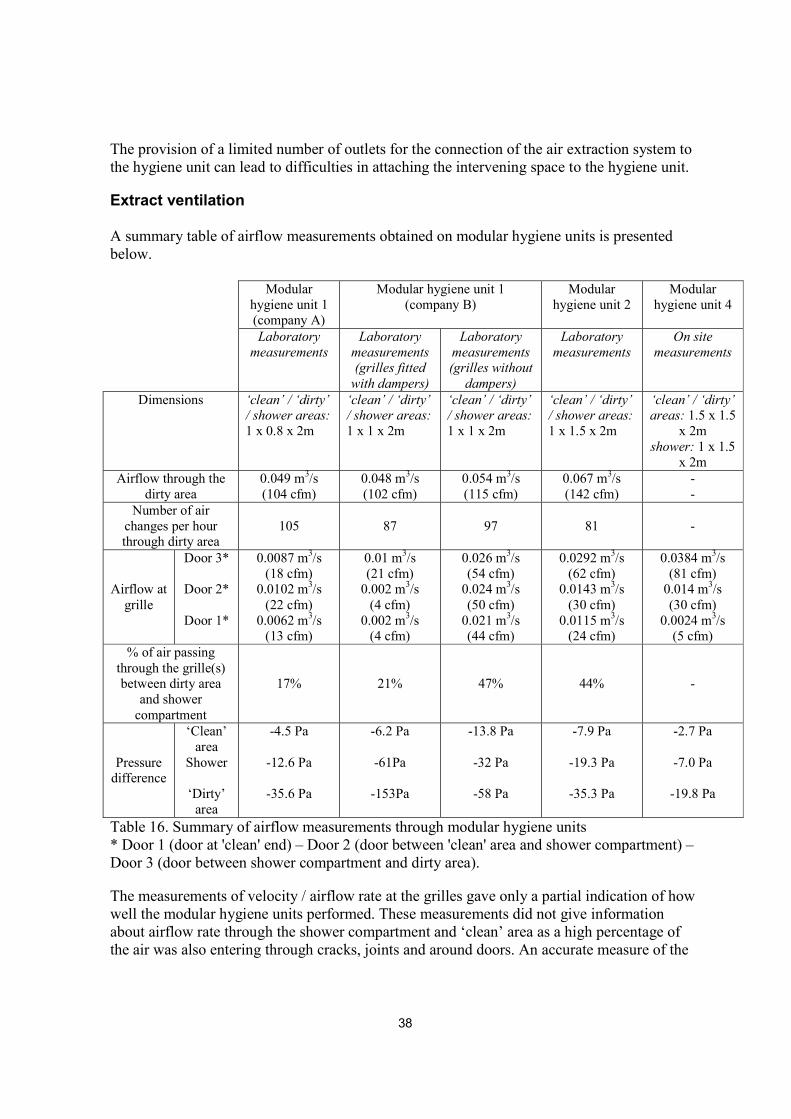
The provision of a limited number of outlets for the connection of the air extraction system to the hygiene unit can lead to difficulties in attaching the intervening space to the hygiene unit.
Extract ventilation A summary table of airflow measurements obtained on modular hygiene units is presented below.
Modular hygiene unit 1 (company A)
Modular hygiene unit 1 (company B)
Modular hygiene unit 2
Modular hygiene unit 4
Laboratory measurements
Laboratory measurements (grilles fitted
with dampers)
Laboratory measurements (grilles without
dampers)
Laboratory measurements
On site measurements
Dimensions ‘clean’ / ‘dirty’ / shower areas: 1 x 0.8 x 2m
‘clean’ / ‘dirty’ / shower areas: 1 x 1 x 2m
‘clean’ / ‘dirty’ / shower areas: 1 x 1 x 2m
‘clean’ / ‘dirty’ / shower areas: 1 x 1.5 x 2m
‘clean’ / ‘dirty’ areas: 1.5 x 1.5
x 2m shower: 1 x 1.5
x 2m Airflow through the
dirty area 0.049 m3/s (104 cfm)
0.048 m3/s (102 cfm)
0.054 m3/s (115 cfm)
0.067 m3/s (142 cfm)
- -
Number of air changes per hour through dirty area
105
87
97
81
-
Airflow at grille
Door 3*
Door 2*
Door 1*
0.0087 m3/s (18 cfm)
0.0102 m3/s (22 cfm)
0.0062 m3/s (13 cfm)
0.01 m3/s (21 cfm)
0.002 m3/s (4 cfm)
0.002 m3/s (4 cfm)
0.026 m3/s (54 cfm)
0.024 m3/s (50 cfm)
0.021 m3/s (44 cfm)
0.0292 m3/s (62 cfm)
0.0143 m3/s (30 cfm)
0.0115 m3/s (24 cfm)
0.0384 m3/s (81 cfm)
0.014 m3/s (30 cfm)
0.0024 m3/s (5 cfm)
% of air passing through the grille(s) between dirty area
and shower compartment
17%
21%
47%
44%
-
Pressure difference
‘Clean’ area
Shower
‘Dirty’ area
-4.5 Pa
-12.6 Pa
-35.6 Pa
-6.2 Pa
-61Pa
-153Pa
-13.8 Pa
-32 Pa
-58 Pa
-7.9 Pa
-19.3 Pa
-35.3 Pa
-2.7 Pa
-7.0 Pa
-19.8 Pa
Table 16. Summary of airflow measurements through modular hygiene units * Door 1 (door at 'clean' end) – Door 2 (door between 'clean' area and shower compartment) – Door 3 (door between shower compartment and dirty area).
The measurements of velocity / airflow rate at the grilles gave only a partial indication of how well the modular hygiene units performed. These measurements did not give information about airflow rate through the shower compartment and ‘clean’ area as a high percentage of the air was also entering through cracks, joints and around doors. An accurate measure of the
39
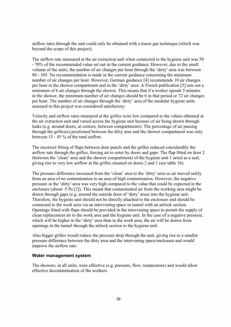
airflow rates through the unit could only be obtained with a tracer gas technique (which was beyond the scope of this project). The airflow rate measured at the air extraction unit when connected to the hygiene unit was 50 - 70% of the recommended value set out in the current guidance. However, due to the small volume of the units, the number of air changes per hour through the ‘dirty’ area was between 80 - 105. No recommendation is made in the current guidance concerning the minimum number of air changes per hour. However, German guidance [4] recommends 10 air changes per hour in the shower compartment and in the ‘dirty’ area. A French publication [5] sets out a minimum of 6 air changes through the shower. This means that if a worker spends 5 minutes in the shower, the minimum number of air changes should be 6 in that period or 72 air changes per hour. The number of air changes through the ‘dirty’ area of the modular hygiene units assessed in this project was considered satisfactory.
Velocity and airflow rates measured at the grilles were low compared to the values obtained at the air extraction unit and varied across the hygiene unit because of air being drawn through leaks (e.g. around doors, at corners, between compartments). The percentage of air passing through the grilles(s) positioned between the dirty area and the shower compartment was only between 15 - 45 % of the total airflow. The incorrect fitting of flaps between door panels and the grilles reduced considerably the airflow rate through the grilles, forcing air to enter by doors and gaps. The flap fitted on door 2 (between the ‘clean’ area and the shower compartment) of the hygiene unit 1 acted as a seal, giving rise to very low airflow at the grilles situated on doors 2 and 1 (see table 16). The pressure difference increased from the ‘clean’ area to the ‘dirty’ area so air moved safely from an area of no contamination to an area of high contamination. However, the negative pressure in the ‘dirty’ area was very high compared to the value that could be expected in the enclosure (about -5 Pa [2]). This meant that contaminated air from the working area might be drawn through gaps (e.g. around the outside door of ‘dirty’ area) into the hygiene unit. Therefore, the hygiene unit should not be directly attached to the enclosure and should be connected to the work area via an intervening space or tunnel with an airlock section. Openings fitted with flaps should be provided in the intervening space to permit the supply of clean replacement air to the work area and the hygiene unit. In the case of a negative pressure, which will be higher in the ‘dirty’ area than in the work area, the air will be drawn from openings in the tunnel through the airlock section to the hygiene unit.
Also bigger grilles would reduce the pressure drop through the unit, giving rise to a smaller pressure difference between the dirty area and the intervening space/enclosure and would improve the airflow rate.
Water management system
The showers, in all units, were effective (e.g. pressure, flow, temperature) and would allow effective decontamination of the workers.

40
Suggestion for the revision of the HSE guidance related to modular units Size of modular hygiene unit for practical use. The minimum size of each compartment, which we would recommend, is 1m x 1m x 2m (height) allowing one worker to use it at a time. The North American ‘Human Dimensions and Interior Space’ by Panero & Zelnik is a source book of design reference standards, which recommends clearances of 1067 x 914 mm. This specification allows someone to bend over and pick up articles from the floor and is appropriate here in the situation where a respirator is worn. However, compartments with dimensions 1m x 1.5m x 2m (height) or 1.5m x 1.5m x 2m (height) offer a more comfortable space in which decontamination can take place. Such units should only be used by one person at a time. Airflow The current guidance document recommends an airflow of 0.1 m3/s through the hygiene unit. However, depending on the size of the unit, the number of air changes per hour will vary. Therefore, it might be more desirable to recommend an airflow for a defined volume or number of air changes / hour. It is recommended to have between 50 and 100 air changes per hour in the ‘dirty area’. The current guidance document is unclear about which flow rate should be measured. When the air extraction unit is connected to the hygiene unit, the airflow rate drops compared with the airflow rate value measured at the air extraction unit with its inlets unsealed and unconnected. Grilles The modular units assessed in this project had sizes of 24 cm x 24 cm for the hygiene unit 1 and 13 cm x 12 cm (two grilles with flaps provided per panel) for the hygiene units 2 and 4. The current guidance document recommends grille sizes of 6 in x12 in (15 cm x 30 cm) with a minimum of 8 in x 9 in (20 cm x 23 cm) for pressure/gravity operated flaps. This is satisfactory as long as the number of air changes per hour is met (see above). The use of larger grilles would increase the volume of air and reduce the pressure difference, and consideration should be given to this design and use of the units. Position and connection to the enclosure Modular hygiene units should not be directly attached to the enclosure and should be connected to the work area via an intervening space or tunnel with a plastic airlock section. This is due to the large pressure drop, which generally occurs through modular hygiene units. The dirty area should have at least three outlets (two on the sides and one in front of the ‘dirty’ end panel / door) for the connection of the air extraction unit to the hygiene unit.
41
The air extraction unit was connected to the extract port of the modular hygiene facility by means of a flexible tube. Future guidance should state that the tubing should be well sealed to the outlet spigot and should be of a suitable length to avoid any twist / bending which might reduce the effectiveness of the air extraction unit. Positioning of provisions It is essential that provisions such as lockers should not block or be placed close to the air extraction ports or ventilation grilles. In the modular unit assessed during this project, these doors opened into the shower compartment. Water management system It is recommended that the water management system is able to pump simultaneously the clean water in and the waste water out of the shower compartment. It is essential that the waste water should be filtered for asbestos fibres before discharge. There is no current specification available for the extraction efficiency of fibres from aqueous suspensions. The manufacturers quote a 5�m filter, although this does not correspond to its filtration size in terms of efficiency. It is not known what the filtration characteristic and efficiency are and further research is needed to ascertain whether it is adequate. References [1] The provision, use and maintenance of hygiene facilities for work with asbestos insulation and coatings, EH47 HSE Books 1990 ISBN 0 11 885567 0. This guidance note has since been revised (2002) and is now called: ‘The provision, use and maintenance of hygiene facilities for work with asbestos insulation, asbestos coating and asbestos insulating board’, ISBN 0 7176 22991. [2] Enclosures provided for work with asbestos insulation, coatings and insulation board, EH51 HSE Books 1999 ISBN 0 7176 1700 9. This guidance note has since been revised (2002) and is now called: ‘Enclosures provided for work with asbestos insulation’, ISBN 0 7176 1700 9. [3] J.M. Harrington, F.S. Gill, T.C. Aw and K. Gardiner, Occupational Health, Fourth Edition, 1998, 423 pages, ISBN 0 632 0482 8 [4] Technical Rules for Hazardous Substances, Asbestos Demolition, reconstruction or maintenance work, TRGS 519, Korrigierte englische Fassung Oktober 99 [5] J.P. Danet F. Dubernet and G. Magniez, Le bilan aéraulique des chantiers d’amiante, Cahiers de notes documentaires, Hygiène et sécurite du travail, 181, 17-40, 2000
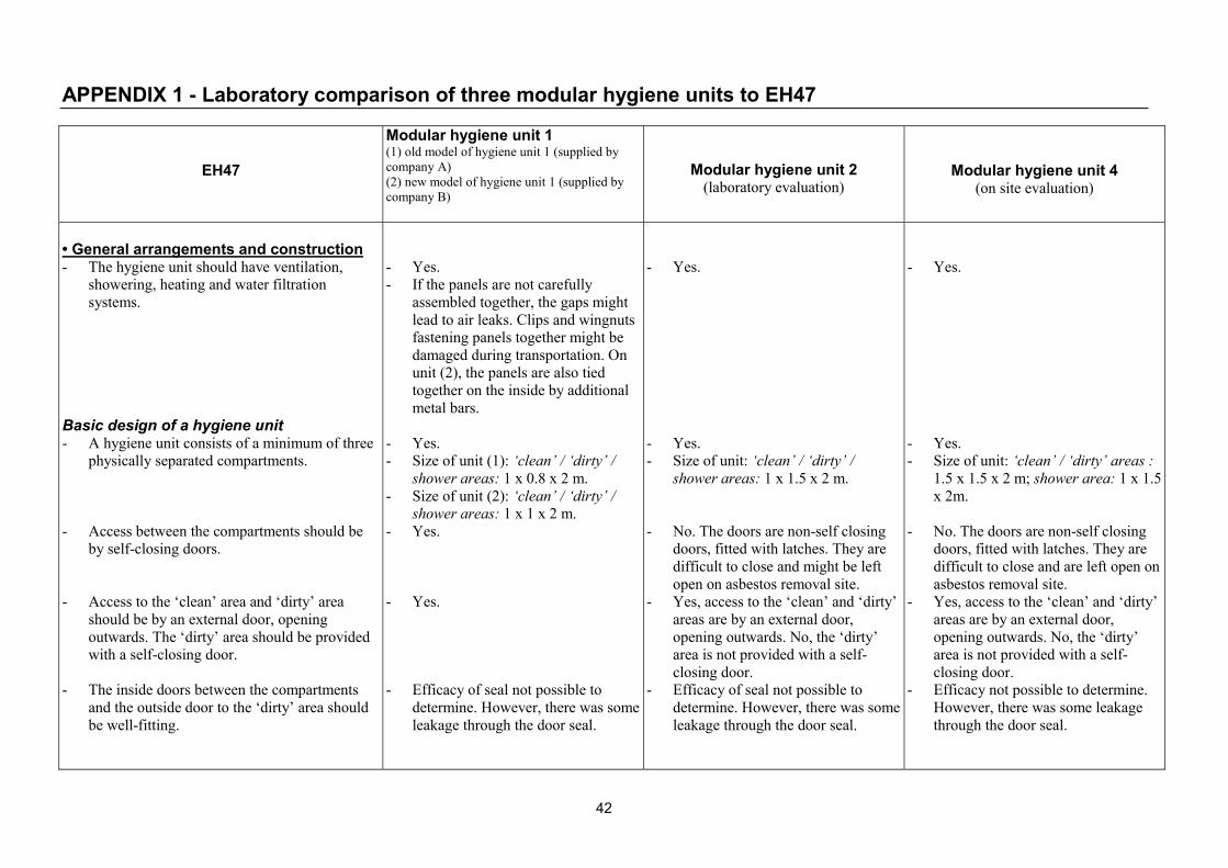
42
APPENDIX 1 - Laboratory comparison of three modular hygiene units to EH47
EH47
Modular hygiene unit 1 (1) old model of hygiene unit 1 (supplied by company A) (2) new model of hygiene unit 1 (supplied by company B)
Modular hygiene unit 2 (laboratory evaluation)
Modular hygiene unit 4 (on site evaluation)
• General arrangements and construction - The hygiene unit should have ventilation,
showering, heating and water filtration systems.
Basic design of a hygiene unit - A hygiene unit consists of a minimum of three
physically separated compartments. - Access between the compartments should be
by self-closing doors. - Access to the ‘clean’ area and ‘dirty’ area
should be by an external door, opening outwards. The ‘dirty’ area should be provided with a self-closing door.
- The inside doors between the compartments
and the outside door to the ‘dirty’ area should be well-fitting.
- Yes. - If the panels are not carefully
assembled together, the gaps might lead to air leaks. Clips and wingnuts fastening panels together might be damaged during transportation. On unit (2), the panels are also tied together on the inside by additional metal bars.
- Yes. - Size of unit (1): ‘clean’ / ‘dirty’ /
shower areas: 1 x 0.8 x 2 m. - Size of unit (2): ‘clean’ / ‘dirty’ /
shower areas: 1 x 1 x 2 m. - Yes. - Yes. - Efficacy of seal not possible to
determine. However, there was some leakage through the door seal.
- Yes. - Yes. - Size of unit: ‘clean’ / ‘dirty’ /
shower areas: 1 x 1.5 x 2 m. - No. The doors are non-self closing
doors, fitted with latches. They are difficult to close and might be left open on asbestos removal site.
- Yes, access to the ‘clean’ and ‘dirty’ areas are by an external door, opening outwards. No, the ‘dirty’ area is not provided with a self- closing door.
- Efficacy of seal not possible to determine. However, there was some leakage through the door seal.
- Yes. - Yes. - Size of unit: ‘clean’ / ‘dirty’ areas :
1.5 x 1.5 x 2 m; shower area: 1 x 1.5 x 2m.
- No. The doors are non-self closing
doors, fitted with latches. They are difficult to close and are left open on asbestos removal site.
- Yes, access to the ‘clean’ and ‘dirty’ areas are by an external door, opening outwards. No, the ‘dirty’ area is not provided with a self-closing door.
- Efficacy not possible to determine. However, there was some leakage through the door seal.

43
Three compartments hygiene unit The ‘clean’ area should have: - fixed seating, - facilities for hanging and drying
decontaminated RPE / drying outdoor clothing and safe storage for personal valuables and clothes;
- respirator battery charging points; - a mirror to help workers adjust their RPE. The shower area should have: - a shower tray and a thermostatically controlled
shower, a rose showerhead; - hooks for hanging towels and RPE undergoing
decontamination; The ‘dirty’ area should have: - an air extraction and filtration unit; - fixed seating; - a wash hand basin with hot and cold running
water (may also be situated in the shower compartment);
Heating - Adequate heating should be used for the
hygiene unit. - Heating appliances should be easily cleaned
- Yes (two-compartment locker,
which can be used as a bench). - Yes (two hooks). - No. - Yes. - Only a rose showerhead. - No provision for holding shampoo,
soap… - Only one hook (not enough). - Yes (situated outside the hygiene
unit) - Yes - No - Yes - Reasonable access.
- Yes (a storage locker, which can be
used as a bench). However, the seat / locker does not have designated fixed position.
- No (a mistake during the setting up of the hygiene unit at the laboratory).
- No. - No (a mistake during the setting up
of the hygiene unit at the laboratory).
- Only a rose showerhead. - The sink can be easily contaminated
and difficult to clean. - Two sets of three / four hooks and a
mirror. - Yes (situated outside the hygiene
unit). - Yes (the storage locker can be easily
contaminated and difficult to 'clean'). The seat / locker does not have designated fixed position.
- No (the sink, provided in the shower
compartment, did not have any drainage system nor separate cold and hot water).
- Yes. - Reasonable access.
- Yes (two storage lockers, which can
be used as a bench). On site, workers placed the seat / lockers close to the air extraction ports (see report).
- Yes - No. - Yes - Only a rose showerhead. - The sink can be easily contaminated
and difficult to clean. - Several hooks and a mirror. - Yes (situated outside the hygiene
unit). - Yes (the storage lockers can be
easily contaminated and difficult to 'clean'). On site, workers placed the seat / lockers close to the air extraction ports (see report).
- No (the sink, provided in the shower compartment, did not have any drainage system nor separate cold and hot water).
- Yes. - Reasonable access.

44
and positioned so that, dust does not accumulate in inaccessible areas
Construction - The hygiene unit must be cleaned easily and
effectively. Asbestos dust must not accumulate in inaccessible places.
Features of the hygiene unit: - The internal walls, ceilings and floors should
be made of smooth and impervious materials. - Angles should be covered for easy cleaning. - Ledges and grooves should be avoided. - Drainage holes should be provided in the floor.- Lighting should be easily cleaned and
positioned so that dust traps are not created. - The windows should be non-opening,
unbreakable and fitted flush with the inner wall surface.
- Lighting should be adequate. - Light switches should be in the ‘clean’ area or
two-way in the ‘clean’ and ‘dirty’ areas.
- Dust may be trapped in small gaps
between panels or panels and roof units if those are not assembled and fastened together correctly.
- Yes - No ledges and grooves. - Yes, in the shower compartment. - No lighting provided. - No windows provided. - No lighting provided. The
transparent ceiling allows light to come in the hygiene unit. No unless strong lighting from outside is provided.
- No.
- Dust may be trapped:
- in gaps between the light fittings and the ceiling (light fittings can be removed for cleaning);
- in gaps behind mirrors/hook holders (mirrors / hooks can be removed for cleaning);
- in the compartment locker placed in the ‘dirty’ area;
- inside the sink unit. - Yes. - Ledges and grooves. - Yes, in the shower compartment. - Lighting is probably easily cleaned
but is positioned so that dust traps are created.
- Yes. - Yes. - No.
- Dust may be trapped:
- in gaps between the light fittings and the ceiling (light fittings can be removed for cleaning);;
- in gaps behind mirrors/hook holders (mirrors / hooks can be removed for cleaning);
- in the compartment locker placed in the ‘dirty’ area;
- inside the sink unit. - Yes. - Ledges and grooves. - Yes, in the shower compartment. - Lighting is probably easily cleaned
but is positioned so that dust traps are created.
- Yes. - Yes. - No.
• Extract ventilation

45
- It is very important to maintain an airflow from the ‘clean’ to the ‘dirty’ area to prevent contaminated air entering the ‘clean’ area.
- The air extraction should discharge through
HEPA or absolute filter. - The air extraction should be positioned at low
level (but sufficiently above floor level not to be damaged by water during floor cleaning); the area beneath the unit should be able to be cleaned.
- The airflow should be of 0.1 m3/s to ensure an
efficient ventilation of the hygiene unit. - The replacement air should enter the facility by
a system of one way grilles with pressure/gravity operated flaps;
- The recommended grilles size is 6 in x 12 in;
the minimum size for grilles with pressure/gravity operated flaps is 8 in x 9 in.
- To enable the extraction to work effectively,
one way grilles should be situated in the internal walls and an air inlet grille in the clean area external wall.
- Yes. - The negative pressure in the ‘dirty’
area (-36 / -60Pa) is very high compared to the value that could be expected in the enclosure (~ -5Pa).
- Yes. - Yes. - The air extraction unit is situated
outside the hygiene unit and is connected to the side of the ‘dirty’ area by means of a flexible tube. There is only one outlet for the connection of the air extraction system to the unit.
- No (~ 0.05m3/s through the dirty area). However, the number of air changes per hour is satisfactory (~ 100 per hour).
- Yes, the replacement air enters the facility by a system of one way grilles but the grilles do not have pressure / gravity operated flaps.
- Size of grilles: 9.65 x 9.65 in. - Airflow rates at the grilles are low
compared to the values obtained at the air extraction unit and varied across the unit (due to air being drawn through leaks). Unit (2) fitted with flaps between door panels and the grilles reduces considerably the airflow rate through the grilles, forcing air to enter by doors and gaps (see report).
- Yes. The grilles are situated on the doors and not on the walls.
- Yes. - The negative pressure in the ‘dirty’
area (-35Pa) is very high compared to the value that could be expected in the enclosure (~ -5Pa).
- Yes. - Yes. - The air extraction unit is situated
outside the hygiene unit and is connected to the side of the ‘dirty’ area by means of two flexible tubes. There are two outlets for the connection of the air extraction system to the unit.
- No (~ 0.07m3/s through the dirty area). However, the number of air changes per hour is satisfactory (~ 80 per hour).
- Yes, the replacement air enters the facility by a system of one way grilles with self-closing flaps.
- Size of grilles: two grilles, each of
5.12 x 4.72cm size. - Airflow rates at the grilles are low
compared to the values obtained at the air extraction unit and varied across the unit (due to air being drawn through leaks).
- Yes.
- Yes. - The negative pressure in the ‘dirty’
area (-20Pa) is high compared to the value that could be expected in the enclosure (~ -5Pa).
- Yes. - Yes. - The air extraction unit is situated
outside the hygiene unit and is connected to the side of the ‘dirty’ area by means of two flexible tubes. There are two outlets for the connection of the air extraction system to the unit.
- (It was not possible to measure the airflow of the unit on site).
- Yes, the replacement air enters the
facility by a system of one way grilles with self-closing flaps.
- Size of grilles: two grilles, each of
5.12 x 4.72cm size. - Airflow rates at the grilles are low
and varied across the unit (due to air being drawn through leaks).
- Yes.
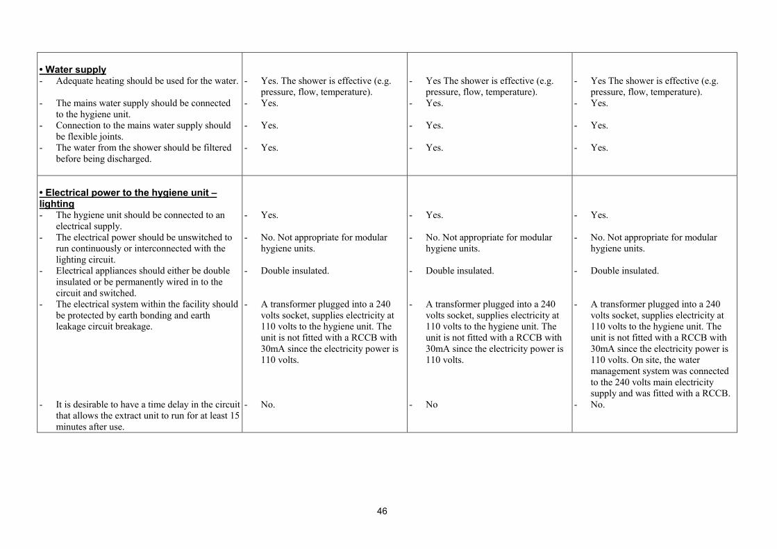
46
• Water supply - Adequate heating should be used for the water. - The mains water supply should be connected
to the hygiene unit. - Connection to the mains water supply should
be flexible joints. - The water from the shower should be filtered
before being discharged.
- Yes. The shower is effective (e.g.
pressure, flow, temperature). - Yes. - Yes. - Yes.
- Yes The shower is effective (e.g.
pressure, flow, temperature). - Yes. - Yes. - Yes.
- Yes The shower is effective (e.g.
pressure, flow, temperature). - Yes. - Yes. - Yes.
• Electrical power to the hygiene unit – lighting - The hygiene unit should be connected to an
electrical supply. - The electrical power should be unswitched to
run continuously or interconnected with the lighting circuit.
- Electrical appliances should either be double insulated or be permanently wired in to the circuit and switched.
- The electrical system within the facility should be protected by earth bonding and earth leakage circuit breakage.
- It is desirable to have a time delay in the circuit
that allows the extract unit to run for at least 15 minutes after use.
- Yes. - No. Not appropriate for modular
hygiene units. - Double insulated. - A transformer plugged into a 240
volts socket, supplies electricity at 110 volts to the hygiene unit. The unit is not fitted with a RCCB with 30mA since the electricity power is 110 volts.
- No.
- Yes. - No. Not appropriate for modular
hygiene units. - Double insulated. - A transformer plugged into a 240
volts socket, supplies electricity at 110 volts to the hygiene unit. The unit is not fitted with a RCCB with 30mA since the electricity power is 110 volts.
- No
- Yes. - No. Not appropriate for modular
hygiene units. - Double insulated. - A transformer plugged into a 240
volts socket, supplies electricity at 110 volts to the hygiene unit. The unit is not fitted with a RCCB with 30mA since the electricity power is 110 volts. On site, the water management system was connected to the 240 volts main electricity supply and was fitted with a RCCB.
- No.

47
APPENDIX 2 - Applicability of EH47 to modular hygiene units
EH47
Modular hygiene unit Recommended specification
DESIGN AND CONSTRUCTION – GENERAL 10. The minimum size of hygiene facilities will vary depending on the number of workers who are to use them. GENERAL ARRANGEMENT 11. ‘A hygiene unit should comprise three separate compartments; a 'clean’ area, a shower area and a ‘dirty’ area’. 11. ‘The compartments should be physically separated and access between them should be by self-closing doors’. 11. ‘Access to the 'clean’ area should be by an external door, preferably opening outwards’. 11. ‘The dirty area should be provided with an outward opening, self-closing external door’. 11. ‘The inside doors between the separate compartments and the outside door to the ‘dirty area’ should be well-fitting’. EXTRACT VENTILATION 12. ‘…provision should be made to allow replacement air to enter the facility by a system of one way grilles as shown in figure 1’. 12. ‘Grille size of between 6in x 12in are recommended with 8in x 9in being the minimum size with pressure/gravity operated flaps’. 13. ‘The air should always be discharged from the facility through a HEPA or absolute filter’ 13. ‘An airflow of 0.1 m3 per second should be sufficient for ventilating most units’. 13. ‘It is advantageous to fit a pre-filter between the air inlet to the extract unit and the HEPA filter. 13. ‘The extract unit should be positioned at low level in the ‘dirty’ area’.
The minimum size of hygiene facilities will vary depending on the number of workers who are to use them. However, each compartment should have a minimum size of 1 x 1 x 2m. Modular decontamination units should be provided with a water management system and an air extraction system. Panels should be carefully assembled together following the manufacturer recommendation and provisions correctly positioned. Essential. Essential. Essential - The clean area should also be provided with an outward opening door. (Note: the space is limited in modular hygiene units) Essential. Essential. Non-self closing doors fitted with latches should be avoided. Essential - The grilles can be positioned on the doors or on the walls. They should be offset to promote efficient air exchange. Essential. Essential. It is recommended to have between 50 and 100 air changes per hour in the dirty area. Essential. Non-applicable. The air extraction unit situated outside the hygiene unit, should be connected to the side of the dirty at low level by means of a flexible tube. Three outlets, capable of being sealed, for the connection of the air extraction unit to the hygiene unit, positioned at low level, in the dirty area. They should be provided at each side and to the front of the unit. The tubing should

48
13. The electrical power of the unit should be unswitched to run continuously or interconnected to the lighting circuit (have a time delay in the circuit that allows the extract unit to run for at least 15 minutes) CONSTRUCTION 14. ‘… all facilities are so constructed that asbestos does not accumulate in inaccessible places and that the facility can be easily and effectively cleaned’. 14. ‘…internal and ceilings should be impervious…’ 14. ‘Floors should be totally covered with an impervious floor covering’. 14. ‘All angles should be covered for easy cleaning.’ 14. ‘Ledges and groves should be avoided’. 14. ‘Drainage holes should be provided in the floor’ 14. ‘Any windows should be non-opening and unbreakable…’ 15. ‘Adequate heating should be provided’. 15. ‘Heating appliances should be of a type that can be easily cleaned and positioned so that dust does not accumulate in inaccessible areas’. 15. ‘Where mains gas or liquefied petroleum gas (LPG) fired heating equipment is used…’ 17. ‘Adequate lighting should be provided…’ 17. ‘Light fittings should be easily cleaned and positioned so that dust traps are not created’. 17. ‘Lighting switches should be by two-way switches in the 'clean' and ‘dirty’ area or in the 'clean' area of the facility’. 17. ‘Electrical appliances should either be double insulated or be permanently wired into the circuit and switched’. CLEAN AREA 18. ‘The 'clean' area should have: fixed seating arrangements, provision for hanging and drying…, safe storage for personal valuables.’ 18. ‘…facilities for battery charging…’ 18. ‘ A mirror should be provided in the 'clean' area…’ SHOWER COMPARTMENT
be properly sealed to the outlet spigot and should be of a reasonable length to avoid any twist / bending. The tubing and connections must be capable of being decontaminated. A sign should be positioned (by the electric outlet) stating that the extract unit should be run for 15 minutes after the last decontamination. Panels should be assembled together so that dust traps are not created and joints should be watertight. Essential. Essential. Essential. Ledges and groves should be avoided or easily to clean.A drainage hole with watertight connections to the water management is essential in the shower compartment. A similar connection for decontamination should be provided in the ‘dirty’ area. Essential. Essential. Essential. Mains gas or liquefied petroleum gas (LPG) fired heating equipment are not suitable for use in modular hygiene units. Essential - Lights should be fitted throughout the facility. Essential. Non-applicable. Essential. Essential. Essential - at least four hooks should be provided. Desirable. Desirable. Essential.

49
19. ‘…with a self-closing door on both sides of the compartment (shower)’. 19. ‘A general ratio of one shower for each four people using the facility is a useful guide…’ 20. ‘The shower compartment should contain: a shower tray, a thermostatically controlled shower, with a rose...’ 20. ‘Hooks should be provided…’ DIRTY AREA 21. ‘The dirty area should have fixed seating…’ 21. ‘A wash hand basin with hot and cold running water … should be provided either in the dirty area or the shower compartments.’ POSITIONING OF HYGIENE FACILITY 22. Hygiene facilities should, where practicable, be positioned close to the work area with an intervening space or tunnel…, connecting the hygiene facility with the stripping enclosure.’ 22. The intervening space will need to act as an air gap between the enclosure and the hygiene facility and should be provided with a vent. MAINTENANCE 35. Maintenance staff carrying out cleaning of the hygiene facility should wear protective clothing and RPE. CONNECTION TO SERVICE
Essential. Modular hygiene unit should only be used by one worker at a time. Desirable. The shower maybe controlled or linked to a water management system situated outside the hygiene unit. Essential. The shower compartment should have provision (e.g. board) for holding shampoo, soap, nails brush… If a sink is provided in the shower compartment, it should be fitted with a drainage pipe. Essential - At least four hooks should be provided. The unit should be provided with effective shower (e.g. pressure, flow, temperature) to allow effective decontamination of the workers. It is recommended that the water management system is able to pump simultaneously the clean water in and the waste water out of the shower compartment. Essential - The dirty area should have fixed appropriate seating (e.g. seating board). The dirty area should not be provided with storage lockers. Desirable. Provisions should not block or be placed close to the air extraction ports or ventilation grilles. Provisions should have designated position in the unit and be fixed by means of screws. Modular hygiene units should not be directly attached to the enclosure and should be connected to the work area via an intervening space and an airlock section, due to the large pressure drop which generally occurs through modular hygiene units. Essential. Maintenance staff carrying out cleaning of the hygiene facility should wear protective clothing and RPE. Care needs to be taken and appropriate protective clothing and RPE to be worn, when disconnecting the contaminated tubing from the hygiene unit / air extraction equipment.

50
39. ‘All purpose-built hygiene facilities should have provision for connection to electric, water and drainage services.’ 39. ‘The electrical system within the facility should be protected by earth bonding and earth leakage circuit breaker.’ 39. ‘Waste water should be piped to the drain and not be allowed to discharge in open channels.’ 39. ‘Connection to the main water supply should be flexible joints…’ 39. The supply should be protected against frost damage.’ COMUNICATION AND TRAINING 41. ‘It is strongly recommended that notices should be fixed to each entrance door clearly indicating which is the 'clean' and which is the dirty entrance, prohibiting unauthorised entry.’ 41. ‘Drain points and electrical connections should be labelled.’
Essential. Essential. Essential - The water should be filtered for asbestos fibres before being sent to the drainage system. Desirable. Desirable. Strongly recommended. Essential.

51
APPENDIX 3 - Measurement of number of air changes per hour in a new hygiene unit (trailer) Air measurements were taken in a purpose-built hygiene unit (trailer) for comparison with modular hygiene units. The purpose-built hygiene unit had two grilles fitted in the walls between the ‘dirty’ area and the ‘shower’ compartment and in the wall between the ‘shower’ area and the ‘clean’ area. It also had one grille allowing air to enter the ‘clean’ area form the outside. The flow rates were measured through the fan and filter unit and through the grilles between the rooms (see table 1 and 2) Grilles /air extraction unit
Point of measurements
Airflow rate (m3/s and m3/h)
Total airflow (m3/h, m3/s)
Total airflow (cfm)
Grille - ‘clean end’
Grille 151 m3/h 0.041 m3/s
151 m3/h 0.042 m3/s
88cfm
Grilles - between ‘clean’ area and shower area
Grille 1 Grille 2
83 m3/h 0.023 m3/s 66 m3/h 0.018 m3/s
148 m3/h 0.041 m3/s
87cfm
Grilles - between shower and ‘dirty’ area
Grille 1 Grille 2
81 m3/h 0.023 m3/s 76 m3/h 0.021 m3/s
157 m3/h 0.044 m3/s
91cfm
Air extraction unit Fan outlet 252 m3/h 0.07 m3/s
252 m3/h 0.07 m3/s
147cfm
Table 1. Airflow measurements at grilles and air extraction unit
Dimensions Airflow through the dirty area
Number of air changes per hour through dirty area
Airflow at grille
% of air passing through the grille(s) between dirty area and shower compartment
Trailer hygiene unit
‘dirty’ area: 1.2 x 2.15 x
2m
252 m3/h 0.07 m3/s �
49
Air extraction unit: 252 m3/h - 0.07 m3/s Door 3*: 157 m3/h - 0.044 m3/s Door 2*: 148 m3/h - 0.041 m3/s Door 1*: 151 m3/h - 0.042 m3/s
62%
Table 2. Airflow measurements through the hygiene unit The two external doors of the unit were fitted with rubber seals. The internal doors between compartments were fitted with foam seals. With the aid of a smoke tube leakage paths were noted around the perimeter of the internal doors.


![To test the effectiveness of Hygiene-Motivation factors …trap.ncirl.ie/1813/1/rajendraghanbahadur.pdf · [Date] To test the effectiveness of Hygiene-Motivation factors on Irish](https://img.pdfslide.net/doc/110x75/5a8f58aa7f8b9af27f8d5ef0/to-test-the-effectiveness-of-hygiene-motivation-factors-trapncirlie18131.jpg)