Embed Size (px)
Citation preview
Investigation of Laplace Barriers for Arrayed Electrowetting Lab-on-a-ChipA. Schultz, I. Papautsky, and J. Heikenfeld*
Department of Electrical Engineering and Computing Systems, University of Cincinnati, Cincinnati, Ohio 45221, United States
ABSTRACT: Partial-post Laplace barriers have been postulatedas a means to allow electrowetting transport and geometricalreshaping of fluids, followed by the preservation of fluidgeometry after the electrowetting voltage is removed. Reportedhere is the first investigation of Laplace barriers with the arrayedelectrodes and splitting/merging transport functions for anelectrowetting lab-on-a-chip. Laplace barriers optimized for 500× 500 μm2 electrodes and 78 μm channel height are shown toprovide geometrical control of fluid shape down to radii ofcurvature of ∼70 μm. The Laplace barriers increase the splittingvolume error, but with proper electrical control, the average error in the split volume is reduced to 5%. Improved programmablefluid storage in droplets or reservoirs and continuous channel flow are also shown. This work confirms the potential benefits ofLaplace barriers for lab-on-a-chip and also reveals the unique challenges and operation requirements for Laplace barriers in lab-on-a-chip applications.
■ INTRODUCTIONMicrofluidics is the driving force behind lab-on-a-chip (LOC)devices that have been developed for medical diagnostics,1−6
chemical1,7−9 and biological sensing,1,4,10−13 and environmentalmonitoring.12−14 These devices primarily use one of twodistinct methods to handle micro/nanoscale volumes of fluids:(1) fixed-channel continuous flow or two-phase microfluidics15
or (2) discrete droplet-based microfluidics. Where continuousflow devices certainly have advantages with respect tosimplicity, reliability, manufacturability, and throughput,16 thediscretization of microfluidics, also known as digital micro-fluidics (DMF), can have advantages in programmability,simplified experiment redesign, reusability, and parallelprocessing.16−18 Recently, researchers have began to unify theadvantages of continuous channel microfluidics and DMF by(1) directly integrating fixed, continuous flow channels with asmall electrowetting DMF grid array;19,20 (2) creatingreconfigurable virtual electrowetting channels;21,22 or (3)integrating Laplace barriers to maintain electrically pro-grammed geometries even when the voltage is removed23,24
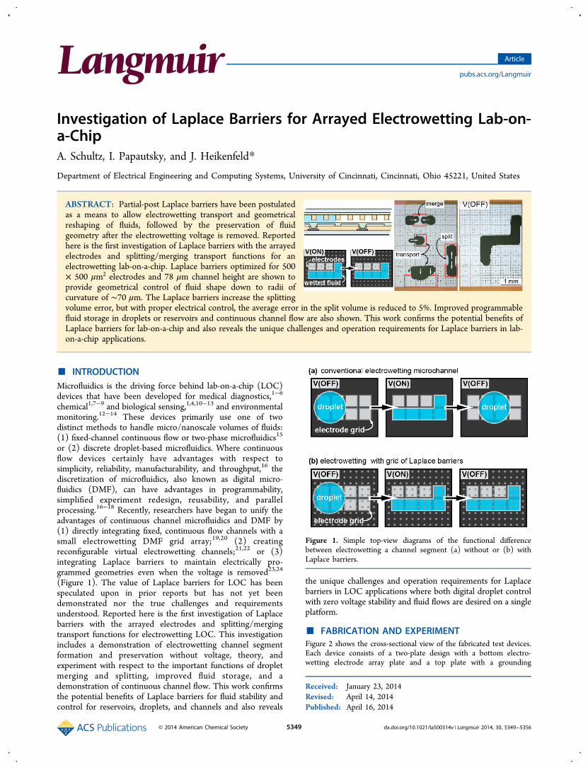
(Figure 1). The value of Laplace barriers for LOC has beenspeculated upon in prior reports but has not yet beendemonstrated nor the true challenges and requirementsunderstood. Reported here is the first investigation of Laplacebarriers with the arrayed electrodes and splitting/mergingtransport functions for electrowetting LOC. This investigationincludes a demonstration of electrowetting channel segmentformation and preservation without voltage, theory, andexperiment with respect to the important functions of dropletmerging and splitting, improved fluid storage, and ademonstration of continuous channel flow. This work confirmsthe potential benefits of Laplace barriers for fluid stability andcontrol for reservoirs, droplets, and channels and also reveals
the unique challenges and operation requirements for Laplacebarriers in LOC applications where both digital droplet controlwith zero voltage stability and fluid flows are desired on a singleplatform.
■ FABRICATION AND EXPERIMENTFigure 2 shows the cross-sectional view of the fabricated test devices.Each device consists of a two-plate design with a bottom electro-wetting electrode array plate and a top plate with a grounding
Received: January 23, 2014Revised: April 14, 2014Published: April 16, 2014
Figure 1. Simple top-view diagrams of the functional differencebetween electrowetting a channel segment (a) without or (b) withLaplace barriers.
Article
pubs.acs.org/Langmuir
© 2014 American Chemical Society 5349 dx.doi.org/10.1021/la500314v | Langmuir 2014, 30, 5349−5356
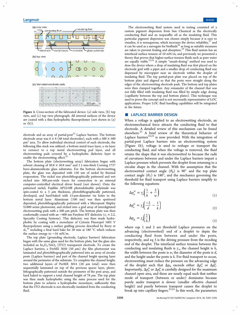
electrode and an array of partial-post23 Laplace barriers. The bottomelectrode array was 6 × 8 (48 total electrodes), each with a 500 × 500μm2 area. To allow individual electrical control of each electrode, thefollowing film stack was utilized: a bottom metal trace layer, a via layerto connect to a top metal electrowetting pad layer, and allelectrowetting pads covered by a hydrophobic dielectric layer toenable the electrowetting effect.25
The bottom plate (electrowetting array) fabrication began withsolvent cleaning of 50.8 × 50.8 mm2 and 1.1-mm-thick Corning 1737boro-aluminosilicate glass substrates. For the bottom electrowettingplate, the glass was deposited with 150 nm of nickel by thermalevaporation. The nickel was photolithographically patterned and wetetched into 300-μm-wide traces for connection to an externalcomputer-controlled electrical driver board (not shown). Onto thepatterned nickel, Fujifilm AP2210B photodefinable polyimide wasspin-coated to a 5 μm thickness, photolithographically patterned,developed, and hard-baked with 15-μm-diameter via holes to thebottom metal layer. Aluminum (100 nm) was then sputtereddeposited, photolithographically patterned with a Microposit ShipleyS1800 series photoresist, and etched into a grid array of interdigitatedelectrowetting pads with a 500 μm pitch. The bottom plate was thenconformally coated with an ∼400 nm Parylene HT dielectric (εr ≈ 2.2,Specialty Coating Systems). This dielectric was then made hydro-phobic by coating with a monolayer of Cytonix Fluoropel 1601 Vfluoropolymer using a surface grafting process described by Berry etal.,26 including a final hard bake for 30 min at 180 °C which reducesthe surface energy to ∼16 mN/m.The top plate (grounding electrode, Laplace barriers) fabrication
began with the same glass used for the bottom plate, but the glass alsoincluded an In2O3/SnO2 (ITO) transparent electrode. To create theLaplace barriers, a PerMX 3050 (50 μm) dry film photoresist waslaminated and photolithographically patterned into an array of circularposts (Laplace barriers) and part of the channel height spacing layeraround the perimeter of the substrate. To complete the channel height,two additional layers of PerMX 3014 (28 μm total) were thensequentially laminated on top of the previous spacer layer, photo-lithographically patterned outside the perimeter of the post array, andhard baked to support a total channel height of 78 μm. The top platewas then made hydrophobic using the same process used for thebottom plate to achieve a hydrophobic monolayer, sufficiently thinthat the ITO electrode is not electrically insulated from the conductingfluid.
The electrowetting fluid system used in testing consisted of acustom pigment dispersion from Sun Chemical as the electricallyconducting fluid and an isoparaffin oil as the insulating fluid. Thisparticular pigment dispersion was chosen simply because it is easy tovisualize, it is nonaqueous, which increases the device reliability,27 andit can be used as a surrogate for biofluids28 as long as suitable measuresare taken to prevent fouling and absoption.29 This fluid system has aninterfacial surface tension of 10 mN/m, and previously we presented atheory that proves that higher-surface-tension fluids such as pure waterare equally viable.23,24 A simple “smash-dosing” method was used todose the device where a drop of insulating fluid was first placed on theelectrode grid with a pipet and a smaller drop of conducting fluid wasdispensed by micropipet near an electrode within the droplet ofinsulating fluid. The top partial-post plate was placed on top of thebottom plate and aligned so that the posts were straight along theedges of the electrowetting electrode pads. The bottom and top plateswere then clamped together. Any remainder of the channel that wasnot fully filled with insulating fluid was filled by simple edge dosing(capillarity between the top and bottom plates). This technique wasused to prove the concept and is not necessarily representative of LOCapplications. Proper LOC fluid handling capabilities will be integratedin the future.
■ LAPLACE BARRIER DESIGNWhen a voltage is applied to an electrowetting electrode, anelectromechanical force attracts the conducting fluid to thatelectrode. A detailed review of this mechanism can be foundelsewhere.25 A brief review of the theoretical behavior ofLaplace barriers23,24 is now provided. With the integration ofpartial-post Laplace barriers into an electrowetting system(Figure 1b), voltage is used to reshape or transport theconducting fluid, and when the voltage is removed, the fluidretains the shape that it was electrowetted to because the radiiof curvatures between and under the Laplace barriers impart aLaplace pressure which prevents the droplet from returning to acircular shape in the channel. With the assumption that theelectrowetted contact angle (θB) is 90° and the top platecontact angle (θT) is 180°, and the mechanics governing thethreshold for fluid transport using Laplace barriers simplify tothe following equations
γΔ = +⎜ ⎟⎛⎝
⎞⎠p
h w1 2
cibtr
(1)
γΔ = − −⎜ ⎟⎛⎝
⎞⎠p
d k2 1
ciutr
(2)
γΔ = ⎜ ⎟⎛⎝
⎞⎠p
h2
ciR (3)
where eqs 1 and 2 are threshold Laplace pressures on theadvancing (electrowetted) end of a droplet to depin theconducting fluid from between and under the posts,respectively, and eq 3 is the driving pressure from the recedingend of the droplet. The interfacial surface tension between theconducting and insulating fluids is γci, the channel height is h,the width between the posts is w, the diameter of the posts is d,and the height under the posts is k. For fluid transport to occur,electrowetting must reduce the pressure on the advancing edgeof the droplet such that ΔpR exceeds either Δputr or Δpbtr.Importantly, Δputr or Δpbtr is carefully designed for the maximumchannel open area, and these are nearly equal such that neithermode of transport (between or under) dominates becausepurely under transport is slower (smaller effective channelheight) and purely between transport causes the droplet tobreak up into capillary fingers.23,24 In this work, the parameters
Figure 2. Cross-section of the fabricated device: (a) side view, (b) topview, and (c) top view photograph. All internal surfaces of the deviceare coated with a thin hydrophobic fluoropolymer (not shown in (a)or (b)).
Langmuir Article
dx.doi.org/10.1021/la500314v | Langmuir 2014, 30, 5349−53565350
satisfying the above design criteria were found to be h = 78 μm,d = 50 μm, k = 28 μm, and w = 75 μm. With these dimensions,a minimum required “threshold” voltage of ∼45 Vpp wasneeded for transport to or draw a droplet from a reservoir.
■ DEMONSTRATION OF BASIC DMF OPERATIONS
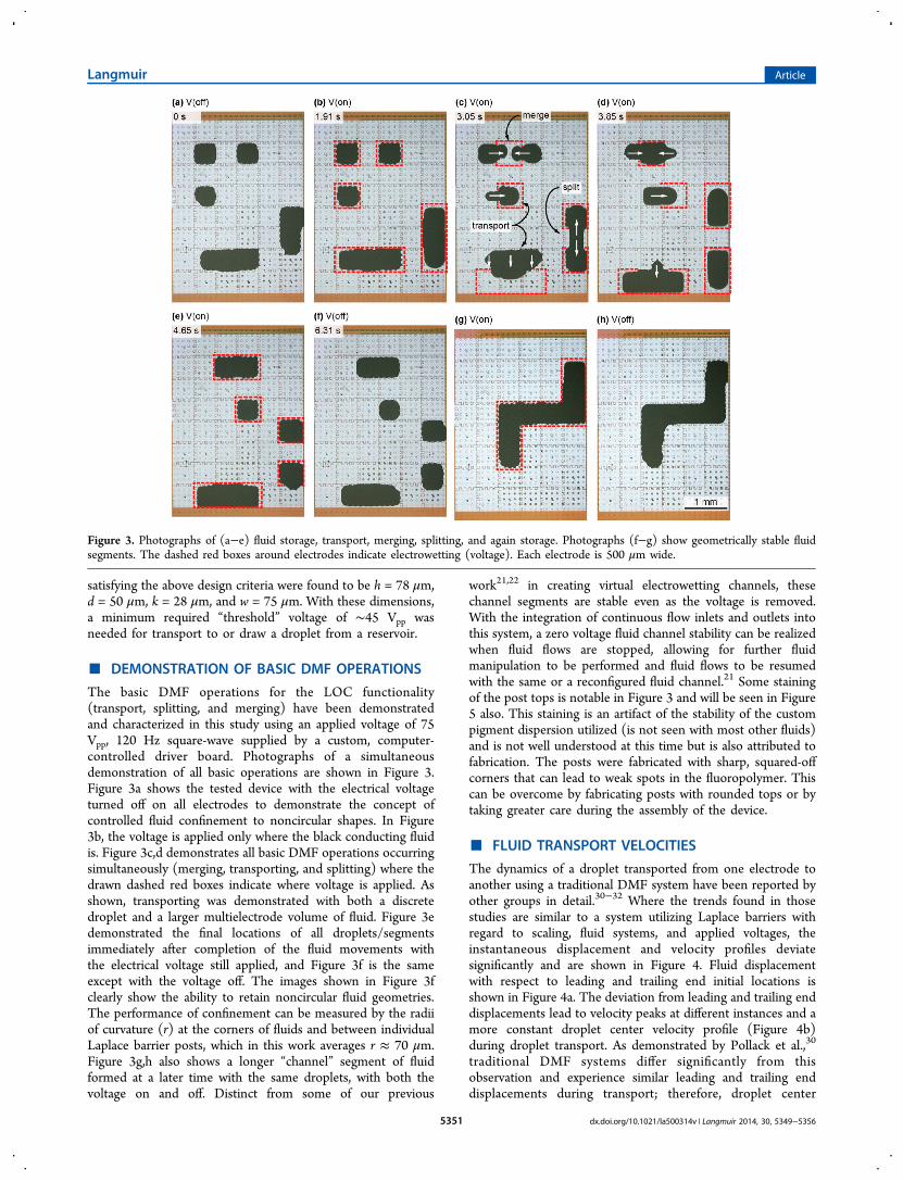
The basic DMF operations for the LOC functionality(transport, splitting, and merging) have been demonstratedand characterized in this study using an applied voltage of 75Vpp, 120 Hz square-wave supplied by a custom, computer-controlled driver board. Photographs of a simultaneousdemonstration of all basic operations are shown in Figure 3.Figure 3a shows the tested device with the electrical voltageturned off on all electrodes to demonstrate the concept ofcontrolled fluid confinement to noncircular shapes. In Figure3b, the voltage is applied only where the black conducting fluidis. Figure 3c,d demonstrates all basic DMF operations occurringsimultaneously (merging, transporting, and splitting) where thedrawn dashed red boxes indicate where voltage is applied. Asshown, transporting was demonstrated with both a discretedroplet and a larger multielectrode volume of fluid. Figure 3edemonstrated the final locations of all droplets/segmentsimmediately after completion of the fluid movements withthe electrical voltage still applied, and Figure 3f is the sameexcept with the voltage off. The images shown in Figure 3fclearly show the ability to retain noncircular fluid geometries.The performance of confinement can be measured by the radiiof curvature (r) at the corners of fluids and between individualLaplace barrier posts, which in this work averages r ≈ 70 μm.Figure 3g,h also shows a longer “channel” segment of fluidformed at a later time with the same droplets, with both thevoltage on and off. Distinct from some of our previous
work21,22 in creating virtual electrowetting channels, thesechannel segments are stable even as the voltage is removed.With the integration of continuous flow inlets and outlets intothis system, a zero voltage fluid channel stability can be realizedwhen fluid flows are stopped, allowing for further fluidmanipulation to be performed and fluid flows to be resumedwith the same or a reconfigured fluid channel.21 Some stainingof the post tops is notable in Figure 3 and will be seen in Figure5 also. This staining is an artifact of the stability of the custompigment dispersion utilized (is not seen with most other fluids)and is not well understood at this time but is also attributed tofabrication. The posts were fabricated with sharp, squared-offcorners that can lead to weak spots in the fluoropolymer. Thiscan be overcome by fabricating posts with rounded tops or bytaking greater care during the assembly of the device.
■ FLUID TRANSPORT VELOCITIES
The dynamics of a droplet transported from one electrode toanother using a traditional DMF system have been reported byother groups in detail.30−32 Where the trends found in thosestudies are similar to a system utilizing Laplace barriers withregard to scaling, fluid systems, and applied voltages, theinstantaneous displacement and velocity profiles deviatesignificantly and are shown in Figure 4. Fluid displacementwith respect to leading and trailing end initial locations isshown in Figure 4a. The deviation from leading and trailing enddisplacements lead to velocity peaks at different instances and amore constant droplet center velocity profile (Figure 4b)during droplet transport. As demonstrated by Pollack et al.,30
traditional DMF systems differ significantly from thisobservation and experience similar leading and trailing enddisplacements during transport; therefore, droplet center
Figure 3. Photographs of (a−e) fluid storage, transport, merging, splitting, and again storage. Photographs (f−g) show geometrically stable fluidsegments. The dashed red boxes around electrodes indicate electrowetting (voltage). Each electrode is 500 μm wide.
Langmuir Article
dx.doi.org/10.1021/la500314v | Langmuir 2014, 30, 5349−53565351
velocities increase to a peak velocity and then decay at a similarrate until the droplet transport is complete. This deviation fromtraditional DMF systems is due to fluid pinning on the posts ofthe trailing end of the droplet. With an applied voltage of 75Vpp, 120 Hz square-wave, the average transport velocitiesranged from 2 to 3 mm/s with transfer rates from 4 to 6 Hz. Byreducing the voltage to 45 Vpp, we reduced the transfer rates to∼1.6 Hz. Increasing the voltage did not significantly increasetransport velocities due to electrowetted contact anglesaturation. As demonstrated in our previous work, by utilizinga higher interfacial tension fluid system and following thesuggestions therein, these transport velocities and transfer rateswill increase.
■ DETAILED STUDY OF SPLITTING ACCURACYFluid splitting in DMF systems occurs with droplet elongationin two opposite directions with a nonenergized electrode in thecenter causing a pinching effect in the middle. According toCho et al.,33 splitting in a traditional DMF system, neglectingcontact angle hysteresis, can be represented in terms of thechannel height, the advancing and necking radii of curvature, R2and R1, respectively, and the top and bottom contact angleswith the following equation:
θ θ= − −RR
Rh
1 (cos cos )2
1
2B T
(4)
When we make the same assumptions for splitting as for fluidtransport, eq 4 becomes
= −RR
Rh
12
1
2
(5)
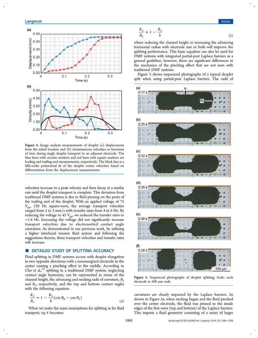
where reducing the channel height or increasing the advancinghorizontal radius with electrode size or both will improve thesplitting performance. This basic equation can also be used forDMF systems with integrated partial-post Laplace barriers as ageneral guideline; however, there are significant differences inthe mechanics of the pinching effect that are not seen withtraditional DMF systems.Figure 5 shows sequenced photographs of a typical droplet
split when using partial-post Laplace barriers. The radii of
curvatures are clearly impacted by the Laplace barriers. Asshown in Figure 5a, when necking began and the fluid pinchedover the center electrode, the fluid was pinned to the insideedges of the first rows (top and bottom) of the Laplace barriers.This imparts a fluid geometry consisting of a series of larger
Figure 4. Image analysis measurements of droplet (a) displacementfrom the initial location and (b) instantaneous velocities as functionsof time during single droplet transport to an adjacent electrode. Theblue lines with circular markers and red lines with square markers areleading and trailing end measurements, respectively. The black line is afifth-order polynomial fit of the droplet center velocities based ondifferentiation from the displacement measurements.
Figure 5. Sequenced photographs of droplet splitting. Scale: eachelectrode is 500 μm wide.
Langmuir Article
dx.doi.org/10.1021/la500314v | Langmuir 2014, 30, 5349−53565352
negative radii of curvature between each post. As the fluidcontinued to elongate longitudinally (Figure 5b), the fluid firstdepinned from the center post, creating a smaller neckingradius of curvature between the first and second rows of posts,longitudinally depinning from adjacent posts in both directionsuntil the fluid pinned to the inside edges of the next row ofposts. As the fluid continued to elongate, the pin−depin−shifteffect occurred with each row of posts (Figure 5c−e) until thedroplet finally split into two discrete droplets and the voltagewas removed (Figure 5f). This behavior suggests that thenumber of posts is odd across each electrowetting pad such thatthe depinning is centered midway to promote equal splittingvolumes.This sequence of fluid pinning to and depinning from the
posts does not necessarily change the overall predictability offluid splitting in the system when using eq 4 or 5, but as noted,post diameter, alignment/location, post height, and the spacebetween posts are extra factors that can affect how the fluidsplits.
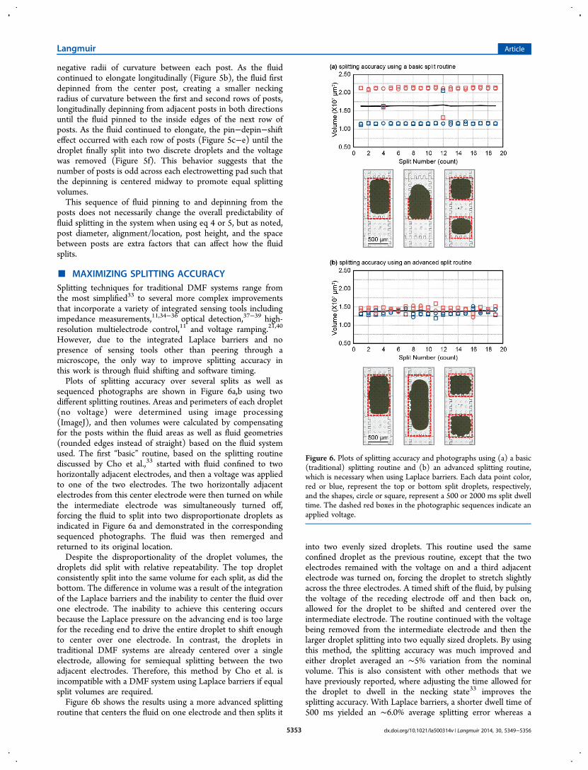
■ MAXIMIZING SPLITTING ACCURACYSplitting techniques for traditional DMF systems range fromthe most simplified33 to several more complex improvementsthat incorporate a variety of integrated sensing tools includingimpedance measurements,11,34−36 optical detection,37−39 high-resolution multielectrode control,11 and voltage ramping.21,40
However, due to the integrated Laplace barriers and nopresence of sensing tools other than peering through amicroscope, the only way to improve splitting accuracy inthis work is through fluid shifting and software timing.Plots of splitting accuracy over several splits as well as
sequenced photographs are shown in Figure 6a,b using twodifferent splitting routines. Areas and perimeters of each droplet(no voltage) were determined using image processing(ImageJ), and then volumes were calculated by compensatingfor the posts within the fluid areas as well as fluid geometries(rounded edges instead of straight) based on the fluid systemused. The first “basic” routine, based on the splitting routinediscussed by Cho et al.,33 started with fluid confined to twohorizontally adjacent electrodes, and then a voltage was appliedto one of the two electrodes. The two horizontally adjacentelectrodes from this center electrode were then turned on whilethe intermediate electrode was simultaneously turned off,forcing the fluid to split into two disproportionate droplets asindicated in Figure 6a and demonstrated in the correspondingsequenced photographs. The fluid was then remerged andreturned to its original location.Despite the disproportionality of the droplet volumes, the
droplets did split with relative repeatability. The top dropletconsistently split into the same volume for each split, as did thebottom. The difference in volume was a result of the integrationof the Laplace barriers and the inability to center the fluid overone electrode. The inability to achieve this centering occursbecause the Laplace pressure on the advancing end is too largefor the receding end to drive the entire droplet to shift enoughto center over one electrode. In contrast, the droplets intraditional DMF systems are already centered over a singleelectrode, allowing for semiequal splitting between the twoadjacent electrodes. Therefore, this method by Cho et al. isincompatible with a DMF system using Laplace barriers if equalsplit volumes are required.Figure 6b shows the results using a more advanced splitting
routine that centers the fluid on one electrode and then splits it
into two evenly sized droplets. This routine used the sameconfined droplet as the previous routine, except that the twoelectrodes remained with the voltage on and a third adjacentelectrode was turned on, forcing the droplet to stretch slightlyacross the three electrodes. A timed shift of the fluid, by pulsingthe voltage of the receding electrode off and then back on,allowed for the droplet to be shifted and centered over theintermediate electrode. The routine continued with the voltagebeing removed from the intermediate electrode and then thelarger droplet splitting into two equally sized droplets. By usingthis method, the splitting accuracy was much improved andeither droplet averaged an ∼5% variation from the nominalvolume. This is also consistent with other methods that wehave previously reported, where adjusting the time allowed forthe droplet to dwell in the necking state33 improves thesplitting accuracy. With Laplace barriers, a shorter dwell time of500 ms yielded an ∼6.0% average splitting error whereas a
Figure 6. Plots of splitting accuracy and photographs using (a) a basic(traditional) splitting routine and (b) an advanced splitting routine,which is necessary when using Laplace barriers. Each data point color,red or blue, represent the top or bottom split droplets, respectively,and the shapes, circle or square, represent a 500 or 2000 ms split dwelltime. The dashed red boxes in the photographic sequences indicate anapplied voltage.
Langmuir Article
dx.doi.org/10.1021/la500314v | Langmuir 2014, 30, 5349−53565353
longer dwell time of 2 s yielded an improved ∼4% averageerror.On the basis of these results, by integrating Laplace barriers
into a DMF system and incorporating a more improvedsplitting technique, splitting accuracies comparable to those oftraditional DMF systems can be achieved.36,41,42 Furtherimprovement is possible with this splitting technique if anautomated imaging feedback or impedance setup is used tosense how far the fluid has shifted and to adjust the shift timeautomatically or compensate for an under or over shift of fluid.
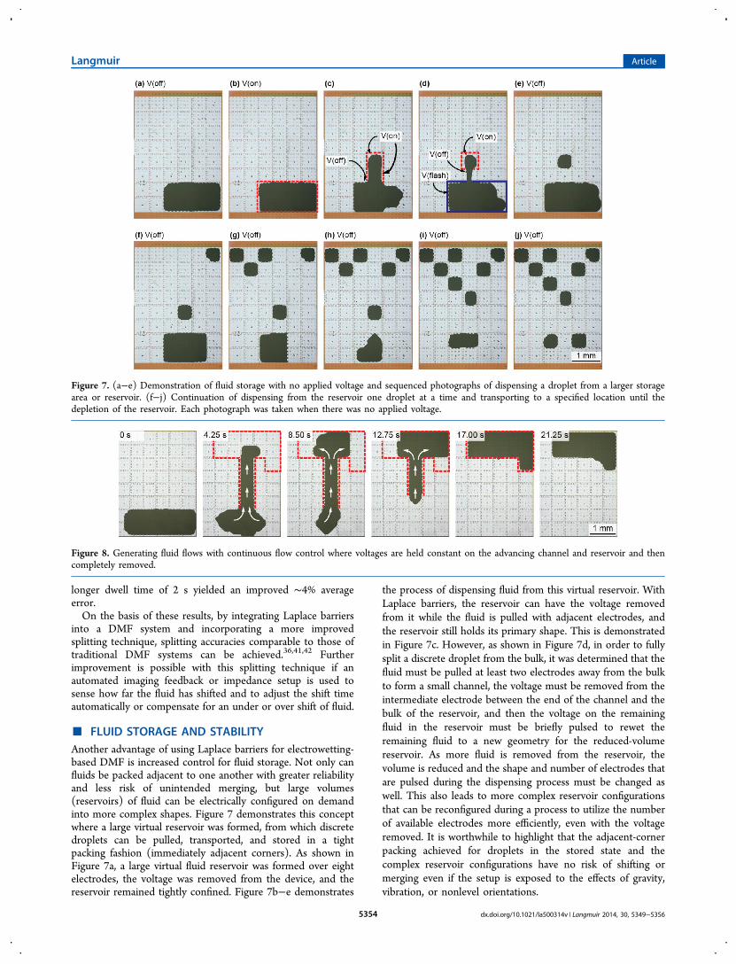
■ FLUID STORAGE AND STABILITYAnother advantage of using Laplace barriers for electrowetting-based DMF is increased control for fluid storage. Not only canfluids be packed adjacent to one another with greater reliabilityand less risk of unintended merging, but large volumes(reservoirs) of fluid can be electrically configured on demandinto more complex shapes. Figure 7 demonstrates this conceptwhere a large virtual reservoir was formed, from which discretedroplets can be pulled, transported, and stored in a tightpacking fashion (immediately adjacent corners). As shown inFigure 7a, a large virtual fluid reservoir was formed over eightelectrodes, the voltage was removed from the device, and thereservoir remained tightly confined. Figure 7b−e demonstrates
the process of dispensing fluid from this virtual reservoir. WithLaplace barriers, the reservoir can have the voltage removedfrom it while the fluid is pulled with adjacent electrodes, andthe reservoir still holds its primary shape. This is demonstratedin Figure 7c. However, as shown in Figure 7d, in order to fullysplit a discrete droplet from the bulk, it was determined that thefluid must be pulled at least two electrodes away from the bulkto form a small channel, the voltage must be removed from theintermediate electrode between the end of the channel and thebulk of the reservoir, and then the voltage on the remainingfluid in the reservoir must be briefly pulsed to rewet theremaining fluid to a new geometry for the reduced-volumereservoir. As more fluid is removed from the reservoir, thevolume is reduced and the shape and number of electrodes thatare pulsed during the dispensing process must be changed aswell. This also leads to more complex reservoir configurationsthat can be reconfigured during a process to utilize the numberof available electrodes more efficiently, even with the voltageremoved. It is worthwhile to highlight that the adjacent-cornerpacking achieved for droplets in the stored state and thecomplex reservoir configurations have no risk of shifting ormerging even if the setup is exposed to the effects of gravity,vibration, or nonlevel orientations.
Figure 7. (a−e) Demonstration of fluid storage with no applied voltage and sequenced photographs of dispensing a droplet from a larger storagearea or reservoir. (f−j) Continuation of dispensing from the reservoir one droplet at a time and transporting to a specified location until thedepletion of the reservoir. Each photograph was taken when there was no applied voltage.
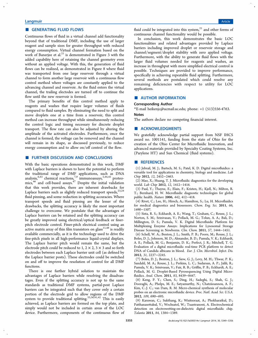
Figure 8. Generating fluid flows with continuous flow control where voltages are held constant on the advancing channel and reservoir and thencompletely removed.
Langmuir Article
dx.doi.org/10.1021/la500314v | Langmuir 2014, 30, 5349−53565354
■ GENERATING FLUID FLOWS
Continuous flows of fluid in a virtual channel add functionalitybeyond that of traditional DMF, including the use of largerreagent and sample sizes for greater throughput with reducedenergy consumption. Virtual channel formation based on thework of Banerjee et al.21 is demonstrated in Figure 3 with theadded capability here of retaining the channel geometry evenwithout an applied voltage. With this, the generation of fluidflows can be realized, as demonstrated in Figure 8 where fluidwas transported from one large reservoir through a virtualchannel to form another large reservoir with a continuous flowcontrol method where voltages are constantly applied to theadvancing channel and reservoir. As the fluid enters the virtualchannel, the trailing electodes are turned off to continue theflow until the new reservoir is formed.The primary benefits of this control method apply to
reagents and washes that require larger volumes of fluidscompared to fluid samples. By eliminating the need to split andmove droplets one at a time from a reservoir, this controlmethod can increase throughput while simultaneously reducingthe control logic and timing necessary for discrete droplettransport. The flow rate can also be adjusted by altering theamplitude of the activated electrodes. Furthermore, once thechannel is formed, the voltage can be removed and the channelwill remain in its shape, as discussed previously, to reduceenergy consumption and to allow on/off control of the flow.
■ FURTHER DISCUSSION AND CONCLUSIONS
With the basic operations demonstrated in this work, DMFwith Laplace barriers is shown to have the potential to performthe traditional range of DMF applications, such as DNAanalysis,6,43 chemical reactions,7,9 immunoassays,5,44,45 proteo-mics,46 and cell-based assays.47 Despite the initial validationthat this work provides, there are inherent drawbacks forLaplace barriers such as slightly reduced transport speeds,23,24
fluid pinning, and some reduction in splitting accuracies. Wheretransport speeds and fluid pinning are the lesser of thedrawbacks, the splitting accuracy is likely the most importantchallenge to overcome. We postulate that the advantages ofLaplace barriers can be retained and the splitting accuracy canbe greatly improved using electrical/optical feedback or finer-pitch electrode control. Finer-pitch electrical control using anactive matrix array of thin film transistors on glass11,48 is readilyavailable commercially, as it is the technology used to drive thefine-pitch pixels in all high-performance liquid-crystal displays.The Laplace barrier pitch would remain the same, but theelectrode pitch could be reduced to 1, 2 × 2, 3 × 3 and so forthelectrodes between each Laplace barrier unit cell (as defined bythe Laplace barrier posts). These electrodes could be switchedon and off to improve the resolution of control for all DMFfunctions.There is one further hybrid solution to maintain the
advantages of Laplace barriers while resolving the disadvan-tages. Even if the splitting accuracy is not up to the samestandards as traditional DMF systems, partial-post Laplacebarriers can be integrated such that they cover only a certainportion of the electrode grid to allow regions of the DMFsystem to provide traditional splitting.33,36,41,42 This is easilyachieved, as Laplace barriers are formed on the top plate, andsimply would not be included in certain areas of the LOCdevice. Furthermore, components of the continuous flow of
fluid could be integrated into this system,21 and other forms ofcontinuous channel functionality would be possible.In conclusion, this work demonstrates the basic LOC
functionalities and related advantages provided by Laplacebarriers including improved droplet or reservoir storage andchannel/segment/droplet stability with zero applied voltage.Furthermore, with the ability to generate fluid flows with thelarger fluid volumes needed for reagents and washes, anincrease in throughput with more simplified electrical control ispossible. Techniques are provided to improve performance,specifically in achieving repeatable fluid splitting. Furthermore,several methods are postulated which could resolve anyremaining deficiencies with respect to utility for LOCapplications.
■ AUTHOR INFORMATIONCorresponding Author*E-mail [email protected]; phone: +1 (513)556-4763.
NotesThe authors declare no competing financial interest.
■ ACKNOWLEDGMENTSWe gratefully acknowledge partial support from NSF IHCSaward no. 1001141, funding from the state of Ohio for thecreation of the Ohio Center for Microfluidic Innovation, andadvanced materials provided by Specialty Coating Systems, Inc.(Parylene HT) and Sun Chemical (fluid systems).
■ REFERENCES(1) Jebrail, M. J.; Bartsch, M. S.; Patel, K. D. Digital microfluidics: aversatile tool for applications in chemistry, biology and medicine. LabChip 2012, 12, 2452−2463.(2) Mao, X.; Huang, T. J. Microfluidic diagnostics for the developingworld. Lab Chip 2012, 12, 1412−1416.(3) Paul, Y.; Thayne, E.; Elain, F.; Kristen, H.; Kjell, N.; Milton, R.T.; Bernhard, H. W. Microfluidic diagnostic technologies for globalpublic health. Nature 2006, 442, 412−418.(4) Rivet, C.; Lee, H.; Hirsch, A.; Hamilton, S.; Lu, H. Microfluidicsfor medical diagnostics and biosensors. Chem. Eng. Sci. 2011, 66,1490−1507.(5) Sista, R. S.; Eckhardt, A. E.; Wang, T.; Graham, C.; Rouse, J. L.;Norton, S. M.; Srinivasan, V.; Pollack, M. G.; Tolun, A. A.; Bali, D.;Millington, D. S.; Pamula, V. K. Digital Microfluidic Platform forMultiplexing Enzyme Assays: Implications for Lysosomal StorageDisease Screening in Newborns. Clin. Chem. 2011, 57, 1444−1451.(6) Schell, W. A.; Benton, J. L.; Smith, P. B.; Poore, M.; Rouse, J. L.;Boles, D. J.; Johnson, M. D.; Alexander, B. D.; Pamula, V. K.; Eckhardt,A. E.; Pollack, M. G.; Benjamin, D. K.; Perfect, J. R.; Mitchell, T. G.Evaluation of a digital microfluidic real-time PCR platform to detectDNA of Candida albicans in blood. Eur. J. Clin. Microbiol. Infect. Dis.2012, 31, 2237−2245.(7) Boles, D. J.; Benton, J. L.; Siew, G. J.; Levy, M. H.; Thwar, P. K.;Sandahl, M. A.; Rouse, J. L.; Perkins, L. C.; Sudarsan, A. P.; Jalili, R.;Pamula, V. K.; Srinivasan, V.; Fair, R. B.; Griffin, P. B.; Eckhardt, A. E.;Pollack, M. G. Droplet-Based Pyrosequencing Using Digital Micro-fluidics. Anal. Chem. 2011, 83, 8439−8447.(8) Keng, P. Y.; Chen, S.; Ding, H.; Sadeghi, S.; Shah, G. J.;Dooraghi, A.; Phelps, M. E.; Satyamurthy, N.; Chatziioannou, A. F.;Kim, C.-J. C.; van Dam, R. M. Micro-chemical synthesis of molecularprobes on an electronic microfluidic device. Proc. Natl. Acad. Sci. U.S.A.2012, 109, 690−695.(9) Karuwan, C.; Sukthang, K.; Wisitsoraat, A.; Phokharatkul, D.;Patthanasettakul, V.; Wechsatol, W.; Tuantranont, A. Electrochemicaldetection on electrowetting-on-dielectric digital microfluidic chip.Talanta 2011, 84, 1384−1389.
Langmuir Article
dx.doi.org/10.1021/la500314v | Langmuir 2014, 30, 5349−53565355
(10) Scullion, M. G.; Di Falco, A.; Krauss, T. F. Slotted photoniccrystal cavities with integrated microfluidics for biosensing applica-tions. Biosens. Bioelectron. 2011, 27, 101−105.(11) Hadwen, B.; Broder, G. R.; Morganti, D.; Jacobs, A.; Brown, C.;Hector, J. R.; Kubota, Y.; Morgan, H. Programmable large area digitalmicrofluidic array with integrated droplet sensing for bioassays. LabChip 2012, 12, 3305−3313.(12) Delattre, C.; Allier, C. P.; Fouillet, Y.; Jary, D.; Bottausci, F.;Bouvier, D.; Delapierre, G.; Quinaud, M.; Rival, A.; Davoust, L.;Peponnet, C. Macro to microfluidics system for biological environ-mental monitoring. Biosens. Bioelectron. 2012, 36, 230−235.(13) Vasudev, A.; Kaushik, A.; Jones, K.; Bhansali, S. Prospects of lowtemperature co-fired ceramic (LTCC) based microfluidic systems forpoint-of-care biosensing and environmental sensing. Microfluid.Nanofluid. 2013, 14, 683−702.(14) Jokerst, J. C.; Emory, J. M.; Henry, C. S. Advances inmicrofluidics for environmental analysis. Analyst 2012, 137, 24−34.(15) Bardin, D.; Kendall, M. R.; Dayton, P. A.; Lee, A. P. Parallelgeneration of uniform fine droplets at hundreds of kilohertz in a flow-focusing module. Biomicrofluidics 2013, 7, 34112.(16) Choi, K.; Ng, A. H. C.; Fobel, R.; Wheeler, A. R. DigitalMicrofluidics. In Annual Review of Analytical Chemistry; Cooks, R. G.,Yeung, E. S., Eds.; Annual Reviews: Palo Alto, CA, 2012; Vol. 5, pp413−440.(17) Fair, R. Digital microfluidics: is a true lab-on-a-chip possible?Microfluid. Nanofluid. 2007, 3, 245−281.(18) Fouillet, Y.; Jary, D.; Chabrol, C.; Claustre, P.; Peponnet, C.Digital microfluidic design and optimization of classic and new fluidicfunctions for lab on a chip systems. Microfluid. Nanofluid. 2008, 4,159−165.(19) Abdelgawad, M.; Watson, M. W. L.; Wheeler, A. R. Hybridmicrofluidics: A digital-to-channel interface for in-line sampleprocessing and chemical separations. Lab Chip 2009, 9, 1046−1051.(20) Watson, M. W. L.; Jebrail, M. J.; Wheeler, A. R. MultilayerHybrid Microfluidics: A Digital-to-Channel Interface for SampleProcessing and Separations. Anal. Chem. 2010, 82, 6680−6686.(21) Banerjee, A.; Kreit, E.; Liu, Y.; Heikenfeld, J.; Papautsky, I.Reconfigurable virtual electrowetting channels. Lab Chip 2012, 12,758−764.(22) Dhindsa, M.; Heikenfeld, J.; Kwon, S.; Park, J.; Rack, P. D.;Papautsky, I. Virtual electrowetting channels: electronic liquidtransport with continuous channel functionality. Lab Chip 2010, 10,832−836.(23) Kreit, E.; Mognetti, B. M.; Yeomans, J. M.; Heikenfeld, J. Partial-post laplace barriers for virtual confinement, stable displacement, and>5 cm s(-1) electrowetting transport. Lab Chip 2011, 11, 4221−4227.(24) Kreit, E.; Dhindsa, M.; Yang, S.; Hagedon, M.; Zhou, K.;Papautsky, I.; Heikenfeld, J. Laplace Barriers for ElectrowettingThresholding and Virtual Fluid Confinement. Langmuir 2010, 26,18550−18556.(25) Mugele, F.; Baret, J.-C. Electrowetting: from basics toapplications. J. Phys.: Condens. Matter 2005, 17, R705.(26) Berry, S.; Fedynyshyn, T.; Parameswaran, L.; Cabral, A.Reversible Electrowetting on Dual-Scale-Patterned Corrugated Micro-structured Surfaces. J. Microelectromech. Syst. 2012, 21, 1261−1271.(27) Chevalliot, S.; Heikenfeld, J.; Clapp, L.; Milarcik, A.; Vilner, S.Analysis of Nonaqueous Electrowetting Fluids for Displays. J. DisplayTechnol. 2011, 7, 649−656.(28) Chatterjee, D.; Hetayothin, B.; Wheeler, A. R.; King, D. J.;Garrell, R. L. Droplet-based microfluidics with nonaqueous solventsand solutions. Lab Chip 2006, 6, 199−206.(29) Yoon, J.-Y.; Garrell, R. L. Preventing Biomolecular Adsorptionin Electrowetting-Based Biofluidic Chips. Anal. Chem. 2003, 75,5097−5102.(30) Pollack, M. G.; Shenderov, A. D.; Fair, R. B. Electrowetting-based actuation of droplets for integrated microfluidics. Lab Chip2002, 2, 96−101.
(31) Bavier̀e, R.; Boutet, J.; Fouillet, Y. Dynamics of droplet transportinduced by electrowetting actuation. Microfluid. Nanofluid. 2008, 4,287−294.(32) Walker, S. W.; Shapiro, B. Modeling the fluid dynamics ofelectrowetting on dielectric (EWOD). J. Microelectromech. Syst. 2006,15, 986−1000.(33) Sung Kwon, C.; Shih-Kang, F.; Hyejin, M.; Chang-Jin, K.Towards Digital Microfluidic Circuits: Creating, Transporting, Cuttingand Merging Liquid Droplets by Electrowetting-Based Actuation. TheFifteenth IEEE International Conference on Micro Electro MechanicalSystems; 2002; pp 32−35.(34) Bhattacharjee, B.; Najjaran, H. Droplet sensing by measuring thecapacitance between coplanar electrodes in a digital microfluidicsystem. Lab Chip 2012, 12, 4416−4423.(35) Shih, S. C. C.; Fobel, R.; Kumar, P.; Wheeler, A. R. A feedbackcontrol system for high-fidelity digital microfluidics. Lab Chip 2011,11, 535−540.(36) Sadeghi, S.; Ding, H.; Shah, G. J.; Chen, S.; Keng, P. Y.; Kim, C.-J. C.; van Dam, R. M. On Chip Droplet Characterization: A Practical,High-Sensitivity Measurement of Droplet Impedance in DigitalMicrofluidics. Anal. Chem. 2012, 84, 1915−1923.(37) Lin, L.; Royal, M. W.; Evans, R.; Fair, R. B.; Jokerst, N. M. ChipScale Optical Microresonator Sensors Integrated With EmbeddedThin Film Photodetectors on Electrowetting Digital MicrofluidicsPlatforms. IEEE Sens. J. 2012, 12, 1794−1800.(38) Zeng, X.; Zhang, K.; Pan, J.; Chen, G.; Liu, A.-Q.; Fan, S.-K.;Zhou, J. Chemiluminescence detector based on a single planartransparent digital microfluidic device. Lab Chip 2013, 13, 2714−2720.(39) Royal, M. W.; Fair, R. B.; Jokerst, N. M. Integrated SamplePreparation and Sensing: Microresonator Optical Sensors Embeddedin Digital Electrowetting Microfluidics Systems. Sensors; IEEE, 28−31Oct 2011; pp 2050−2053.(40) Banerjee, A.; Liu, Y.; Heikenfeld, J.; Papautsky, I. Deterministicsplitting of fluid volumes in electrowetting microfluidics. Lab Chip2012, 12, 5138−5141.(41) Ren, H. Automated on-chip droplet dispensing with volumecontrol by electro-wetting actuation and capacitance metering. Sens.Actuators, B 2004, 98, 319−327.(42) Gong, J.; Kim, C. C. J. All-electronic droplet generation on-chipwith real-time feedback control for EWOD digital microfluidics. LabChip 2008, 8, 898−906.(43) Hoshino, T.; Inagaki, F. Molecular quantification of environ-mental DNA using microfluidics and digital PCR. Syst. Appl. Microbiol.2012, 35, 390−395.(44) Miller, E. M.; Ng, A. H.; Uddayasankar, U.; Wheeler, A. R. Adigital microfluidic approach to heterogeneous immunoassays. Anal.Bioanal. Chem. 2011, 399, 337−345.(45) Ng, A. H.; Uddayasankar, U.; Wheeler, A. R. Immunoassays inmicrofluidic systems. Anal. Bioanal. Chem. 2010, 397, 991−1007.(46) Jebrail, M. J.; Luk, V. N.; Shih, S. C. C.; Fobel, R.; Ng, A. H. C.;Yang, H.; Freire, S. L. S.; Wheeler, A. R. Digital Microfluidics forAutomated Proteomic Processing. J. Vis. Exp. 2009, e1603.(47) Bogojevic, D.; Chamberlain, M. D.; Barbulovic-Nad, I.; Wheeler,A. R. A digital microfluidic method for multiplexed cell-basedapoptosis assays. Lab Chip 2012, 12, 627−634.(48) Noh, J. H.; Noh, J.; Kreit, E.; Heikenfeld, J.; Rack, P. D. Towardactive-matrix lab-on-a-chip: programmable electrofluidic controlenabled by arrayed oxide thin film transistors. Lab Chip 2012, 12,353−360.
Langmuir Article
dx.doi.org/10.1021/la500314v | Langmuir 2014, 30, 5349−53565356