Embed Size (px)
Citation preview
AFFTC-TR-76-36
INVESTIGATION OF PITOT AND STATICSYSTEM LEAK EFFECTS
A December 1976
p Final Report
F
This document has been approved for publicrelease and resale; its distribution isunlimited.
EDAIRD FORC FOC TROT CENTEREDWARS AI FOR EBASE, CALIFORNIA
AIR FORCE SYSTEMS COMMANDUNITED STATUS AIR FORCE
This technical report was submitted under Job Order Numberby the Deputy Commander for Operations of the Air Force Plight TstwoCenter, Edwards APB, California 93523.
This report has been reviewed and cleared for open publication and/or public release by the AFPTC Office of Information in accordance withAPR 190-17 and DODD 5230.9. There is no objection to unlimited distri-bution of this report to the public at large, or by DDC to the NationalTechnical Information Service.
This report has been reviewedPrepared by: and is approved for publication:
27 December 1976
MICHAEL F. MARQUARDT LARRY OVMcCLAINCaptain, USAF Colonel, USAFAerospace Engineer Asst Deputy Connander for Operations
Major General, SfCommander
When U. S. Government drawings, specifications, or other dataare used for any purpose other than a definitely relatedgovernment procurement operation, the government thereby in-curs no responsibility nor any obligation whatsoever; andthe fact that the government may have formulated, furnished,or in any way supplied the said drawings, specifications, orany other data is not to be regarded by implication or other-wise, as in any manner licensing the holder or any other personor corporation or conveying any rights or permission to manu-facture, use or sell any patented invention that may in any waybe related thereto.
Do not return this copy; retain or destroy.
tm
a
UNCLASSIFIEDSECURITY CLASSIFICATION OF THIS PAGE (*%on Data ,nt.,.e)
REPORT DOCUMENTATION PAGE READ CNSTTION OsR R k ' -- 2. GOVT ACCESSION NO. 3. RECIPIENT'S CATALOG NUMBER
AFFTC-TR-76-36 /4. TITLE ( d ub tl . . . .PE O F R PO RT & PERIOD COVERED
,,.INVESTIGATION OF PITOT AND STATIC SYSTEMLEAK EFFECTS. Z nal # 7ep t NUM
7. AUTHOR(e) 8. CONTRACT OR GRANT NUMBER(&)
j \ .&_PFRFOl uriu frp MIZ7ATItN M AND ADDRESS 10. PROGRAM ELEMENT, PROJECT, TASKMichael F. Marquardt Captain, USAF AREA h WORK UNIT NUMBERS
PEC _ 114FII. CONTROLLING OFFICE NAME AND ADDRESS q
Decabn 1976tic99 mFWor PAGr
III. MONITORING AGENCY NAME A A RES I2 diilsata from Controlling Office) Is. SECURITY CLASS. (of this report)
// '. Unclassified
IS&. DECL ASSI FICATION/DOWNGRADINGSCHEDULE
IS. DISTRIBUTION STATEMENT (of this Report)
This document has been approved for public release and resale;its distribution is unlimited.
17. DISTRIBUTION STATEMENT (of the abstract entered in Block 20, if different from Report)
IS. SUPPLEMENTARY NOTES
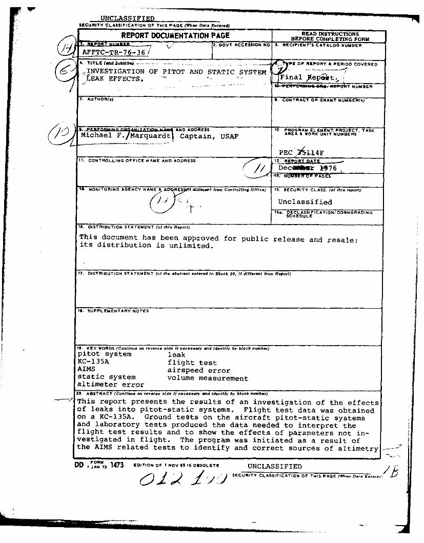
IS. KEY WORDS (Continue on revere side if necessary and identify by block number)pitot system leakKC-135A flight testAIMS airspeed errorstatic system volume measurementaltimeter error
20. ABSTRACT (Continue on reverse side it necessary and Identify by block number)
-'- This report presents the results of an investigation of the effectsof leaks into pitot-static systems. Flight test data was obtainedon a KC-135A. Ground tests on the aircraft pitot-static systemsand laboratory tests produced the data needed to interpret theflight test results and to show the effects of parameters not in-vestigated in flight. The program was initiated as a result ofthe AIMS related tests to identify and correct sources of altimetry
DD I J 1473 EDITION OF I NOV 65 IS OBSOLETE UNCLASSIFIEDcOL 2-<'>'J SECURITY CLASSIFICATION OF THIS PAGE rWhen Dete Entere! -,
UNCLASSIFIEDSECURITY CLASSIFICATION OF THIS PAOE(Wha, Dea Raterea,
system errors. The tests identified the primary parameters affect-ing leak-induced altimeter errors as leak hole size and pressuredifferential across the hole for a specific system geometry.Secondary effects were leak location, airspeed, and to a limitedextent, altitude. The static system volume significantly affectedthe rate of change of indicated altimeter values during ground leakchecks. Airspeed indicator errors due to pitot system leaks wereprimarily dependent on airspeed, cabin pressure, and leak hole size.-Pitot system volume would affect the magnitude of indicated leakrate during a leak check. Data analysis required use of leakcheck methods different from those usually applied to pitot-staticsystems. It was found that a static pressure system leak checkcriteria based solely on permissible altitude error might allowleaks which were unacceptably large when system integrity was con-sidered. -The c6ntinued use of current Air Force pitot-static sys-tem leak check criteria should result in negligible airspeed andaltitude errors.
UNCLASSIFIEDSECURITY CLASSIFICATION OF THIS PAGE(Wh n Dea Entered)
SUMMARY
The DOD AIMS program investigated the magnitide of altimeter errorsdue to pressure fields and equipment. The error due to static systemleaks was recognized as an unknown quantity. A test program on a T-38identified the altimeter errors at several flight conditions for knownleak rates. The test program on the AFFTC NKC-135A was establishedto investigate the effects of leaks in the pitot-static system of a largeaircraft and to determine what variables, including system volume,affected the magnitude of leak-induced altimeter and airspeed errors.Major emphasis was placed on altimeter error information.
Laboratory tests were conducted to establish calibrations for theleak valves used on the test flights and to attempt to create a gener-alized model which could be applied to analysis of flight test dataand used to predict the errors in a different aircraft static system.Static system volume was found to be one of the principal parametersaffecting the results of a leak test on a static system, i.e., a smallvolume system caused a more rapid altimeter response to a ground testleak than did a large volume system. A method to determine systemvolume was confirmed by laboratory tests and the effect of volume onleak rate through the calibrated leak valves was ascertained. Thevolumes of the test pitot-static systems on the test aircraft weremeasured and found to be less than those on a typical fighter-classaircraft.
Pressure differential across a leak valve was found to be a keyparameter in both laboratory and flight test data. In order to correlateground test data and develop a generalized presentation of leak effectson KC-135A aircraft, ground test leak rate data was analyzed at oneparticular leak valve pressure differential. New leak check proceduresbased on a constant pressure differential were developed for utilizationof KC-135A leak effects presented in this study.
Pneumatic-mechanical instruments were not sensitive enough to pro-duce data which delineated the trends and relative effects of the variousparameters affecting the leak-induced errors. W se of electrical digitaloutput altimeters produced data with less scatter.
Altimeter errors were found to depend primarily on leak hole sizeand cabin pressure differential and secondarily on altitude, airspeed,and leak location relative to the altimeter. An increase in the primaryparameters caused an increase in the altimeter error (indicated alti-tude less than actual flight altitude). The leak closest to he altimetercaused the greatest error. Increasing airspeed caused sliglitly greateraltimeter errors. The computed pressure error sensed by the altimeterincreased slightly with increasing flight altitude. Thus, the altimetererror for a leak at a high altitude would be greater than predicted byuse of the standard atmosphere equations applied to pressure error dataacquired at a lower flight altitude. Leak-induced airspeed errors werefound to depend on leak hole size, airspeed, and cabin pressure differ-ential. Static system leaks caused lower airspeed readings and pitotsystem leaks caused higher readings at the airspeeds flown during thetests. Pitot-leak induced airspeed errors increased with increasingleak hole size and cabin pressure differential and decreased with in-creasing airspeed.
Leak check rate of descent was found to increase with increasing
1i
hole size, increasing pressure differential, and decreasing systemvolume. For the same indicated leak rate, a large volume system couldbe expected to have a greater altitude error because the leak hole andstabilized leak flow rate would be larger. System configuration canaffect the altimeter error by the extent that the stabilized leak flowis restricted beyond the leak hole.
It appears that current Air Force leak rate criteria result innegligible altitude errors. Leak rates must reach several thousandfeet per minute before their effect is noticeable. The relationshipbetween the maximum allowable leak-induced altitude error for an air-craft and the AIMS criteria will depend on the altitude error curveresulting from all other causes.
2
PREFACE
The test program was initiated at the request of the AIMS SystemProgram Office (SPO) and was initially authorized by AFFTC ProjectDirective 74-3, 6 July 1973. Before the test was cu.mpleted, the AIMSflight test program was terminated and the AIMS SPO was deactivated.The test was then completed as an AFFTC in-house project under AFFTCProject Directive 74-3A, 16 May 1974.
The author wishes to acknowledge the contributions of severalpeople associated with this project. Lt Col Michael V. Love was theprogram manager. Captains Paul J. Mathieu and Gary W. Clark wereassigned consecutively as project engineers. Mr. Willie L. Allen andMr. Albert G. DeAnda assisted the engineering effort during parts ofthe planning, testing, and data analysis phases of the program.
3
TABLE OF CONTENTS
Page No.
LIST OF ILLUSTRATIONS 6
INTRODUCTION 8
Background 8
Objectives 8
INSTRUMENTATION 9
TEST METHODS AND CONDITIONS 12
Ground Tests 12
Laboratory Tests 12
Aircraft Tests 15
Flight Tests 19
TEST RESULTS 23
CONCLUSIONS AND RECOMMENDATIONS 27
REFERENCES 28
APPENDIX A - DATA ANALYSIS METHODS 29
APPENDIX B - TEST DATA 47
APPENDIX C - TEST RESULTS FOR TEST AIRCRAFT 64
LIST OF ABBREVIATIONS AND SYMBOLS 82
5
LIST OF ILLUSTRATIONS
Figure Title Page No.
1 Schematic of Test Instrumentation on Test 10Aircraft
2 Diagram of Pitot-Static System on Test Aircraft 1i
3 Schematic of Apparatus Used to Calibrate Leak 13Valves and Determine Volume Effects on GroundLeak Rates
4 Sample of Leak Valve Calibration Data 14
5 Leak-Induced Rate of Descent Variation with 16Volume
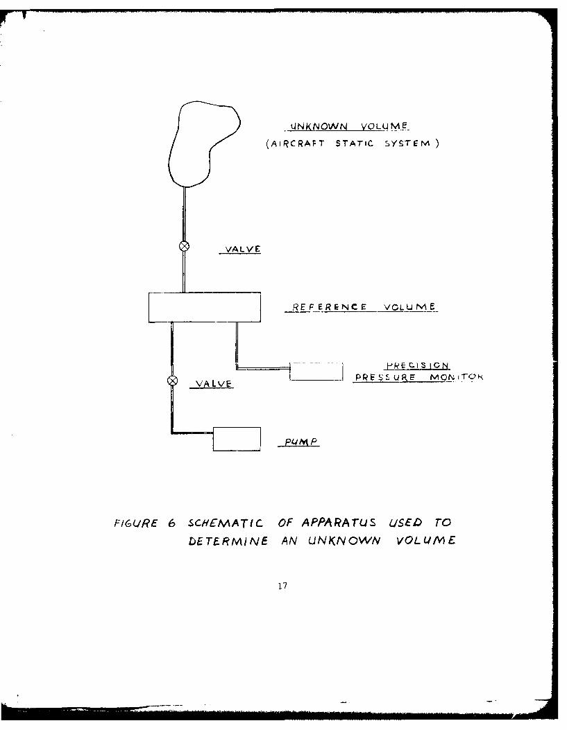
6 Schematic of Apparatus Used to Determine an 17Unknown Volume
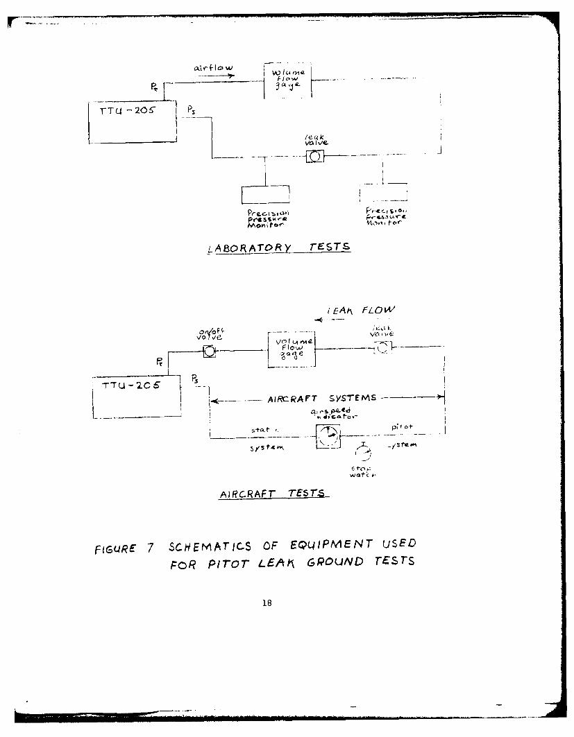
7 Schematics of Equipment Used for Pitot Leak 18Ground Tests
8 Cabin Altitude Schedule 21
9 Airspeed vs Cabin Differential Pressure for 22No Airspeed Error Due to a Pitot Leak
Appendix A
Al Definitions and Flow Chart for Static Leak 30Ground Test Data Analysis
A2 Definitions and Flow Chart for Flight Test 31Data Analysis and Data Correlation for StaticLeaks
A3 Recommended Conditions for Static Leak Check 32
A4 Description of Analysis of Pitot Leak Ground 34Test Data
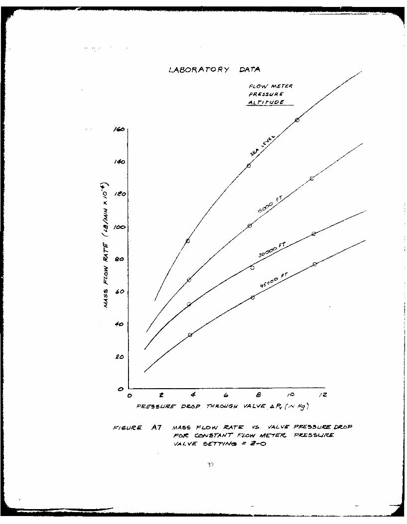
A5-A7 Mass Flow Rate vs Valve Pressure Drop for 35-37Constant Flowmeter Pressure
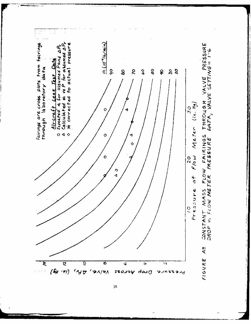
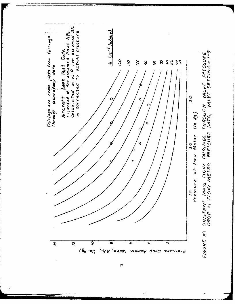
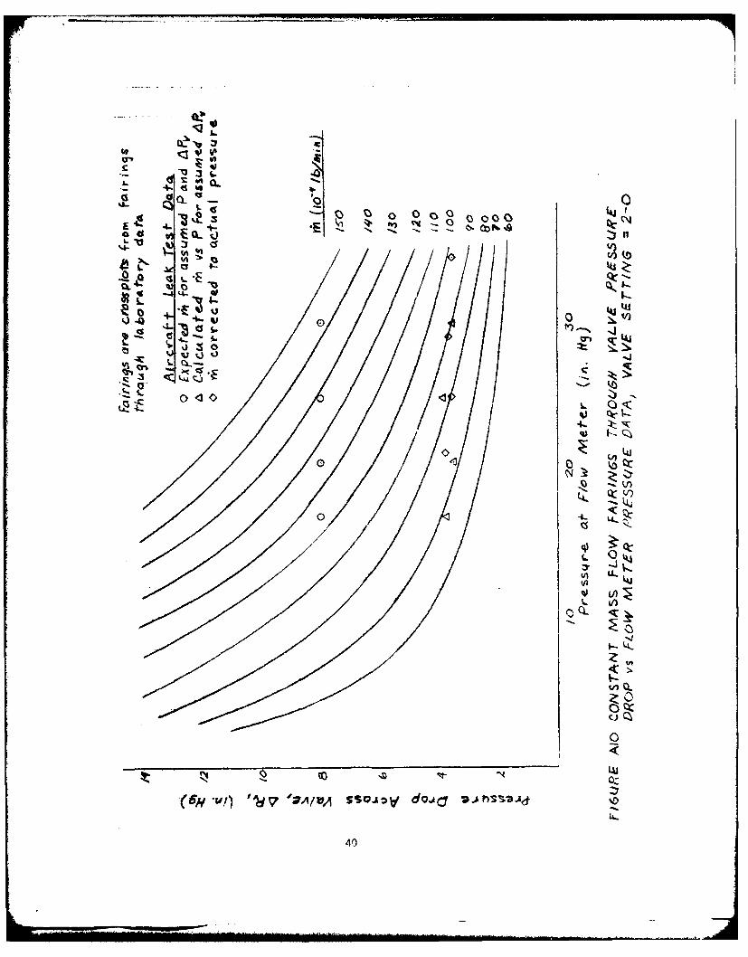
A8-A10 Constant Mass Flow Fairings Through Valve 38-40Pressure Drop vs Flowmeter Pressure Data
All Leak Test Rate of Airspeed Decrease vs Mass 41Flow Rate for Test Pitot System
A12 Definitions for Analysis of Pitot Leak Flight 44Test Data
A13 Flight Test Data for Pitot Leaks 45
A14 Data Correlation for Pitot Leak Test 46
6
Figure Title Page No.
Appendix B
B1 Altimeter Error Dependence on Airspeed 48
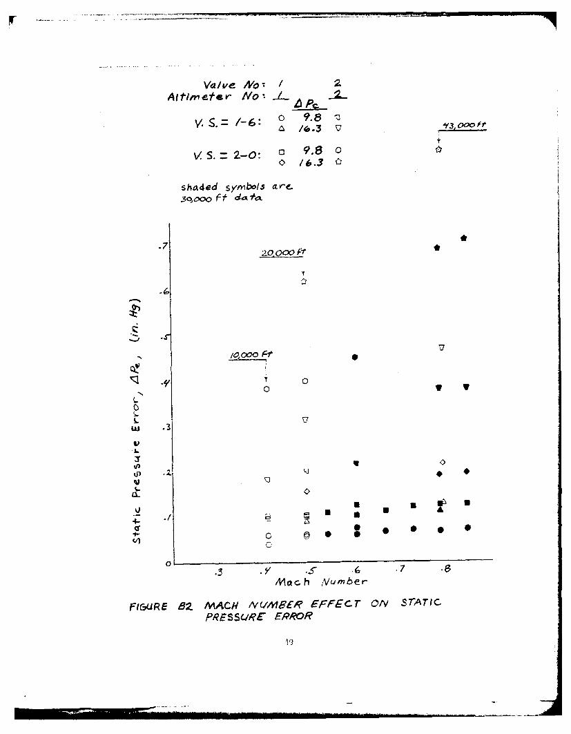
B2 Mach Number Effect on Static Pressure Error 49
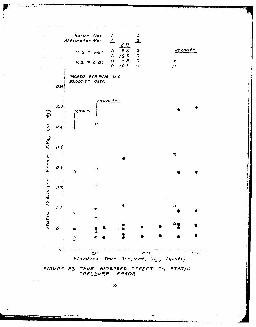
B3 True Airspeed Effect on Static Pressure Error 50
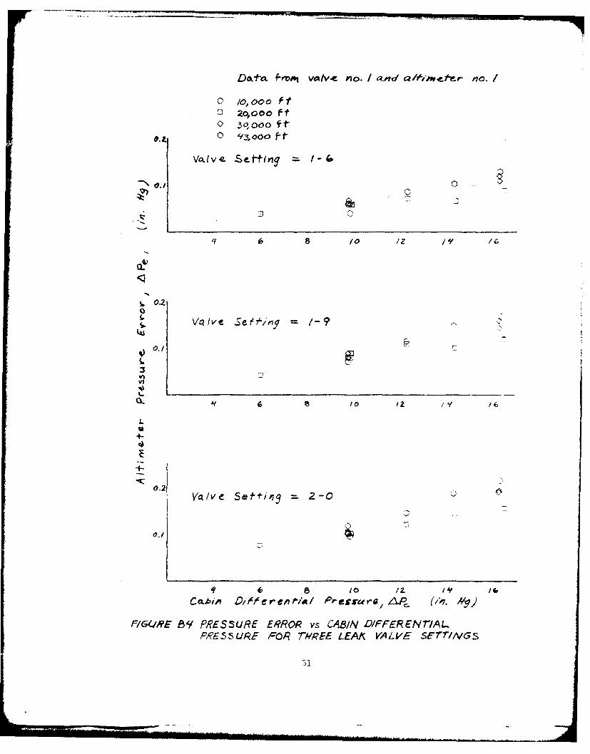
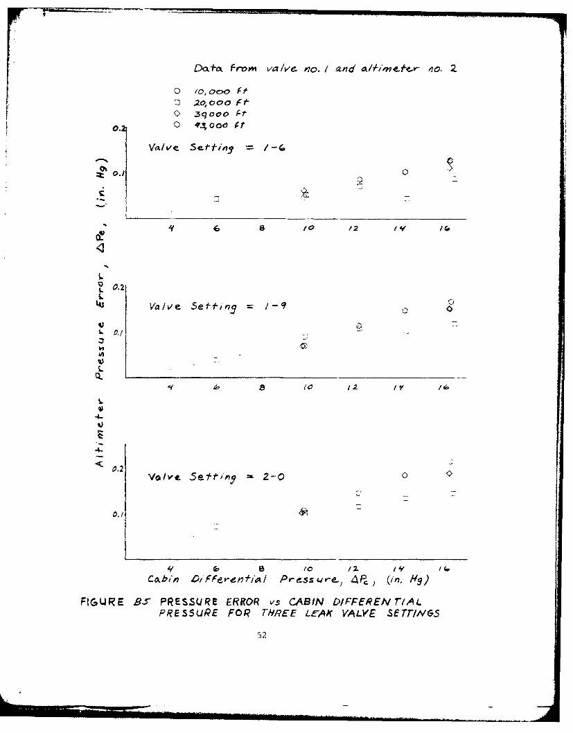
B4-B7 Pressure Error vs Cabin Differential Pressure 57-54for Three Leak Valve Settings
B8 Comparison of Leak-Induced Errors Measured 55at and Upstream of Leak
B9 Comparison of Leak-Induced Errors Measured 56at and Downstream of Leak
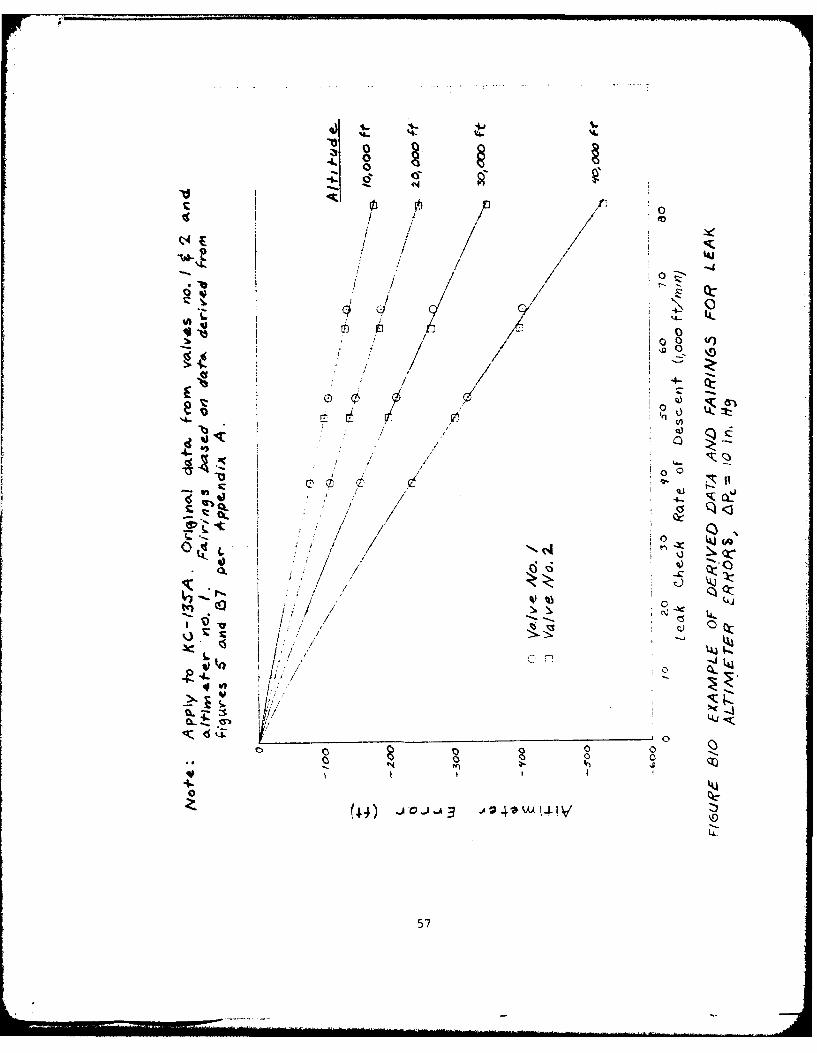
B10 Example of Derived Data and Fairings for Leak 57Altimeter Errors, APc = 10 in. Hg
BlI Example of Derived Data and Fairings for Leak 58Altimeter Errors, Hc = 30,000 ft
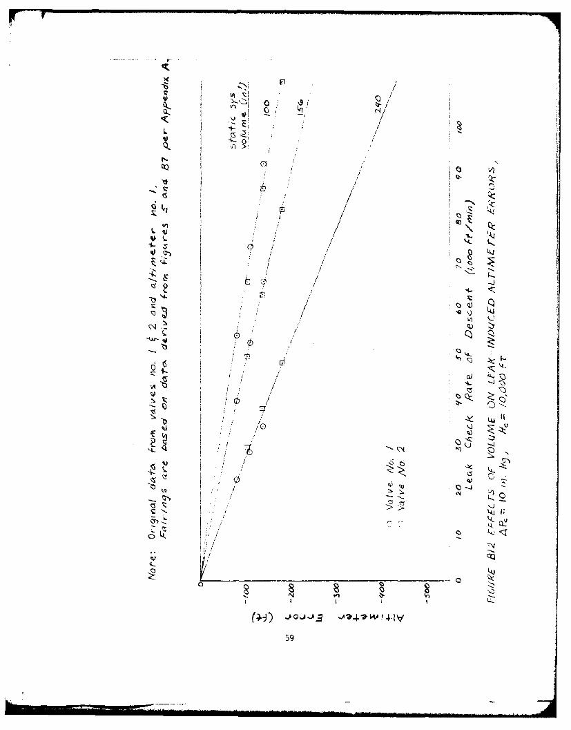
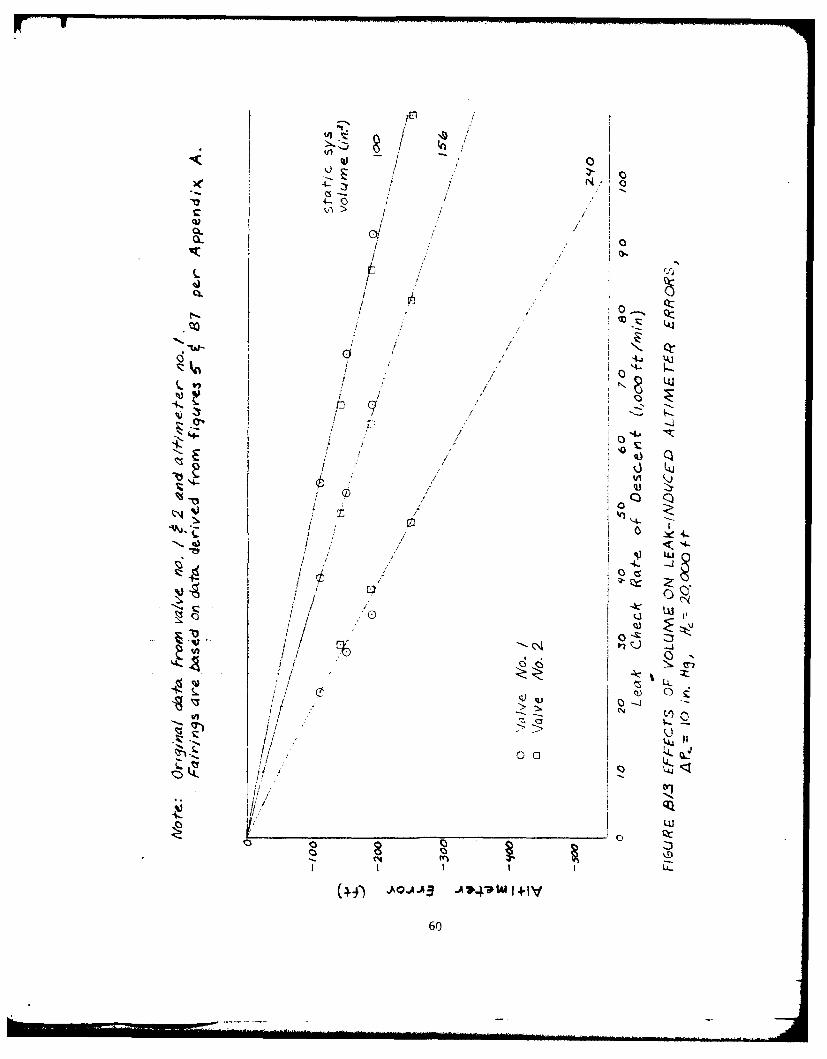
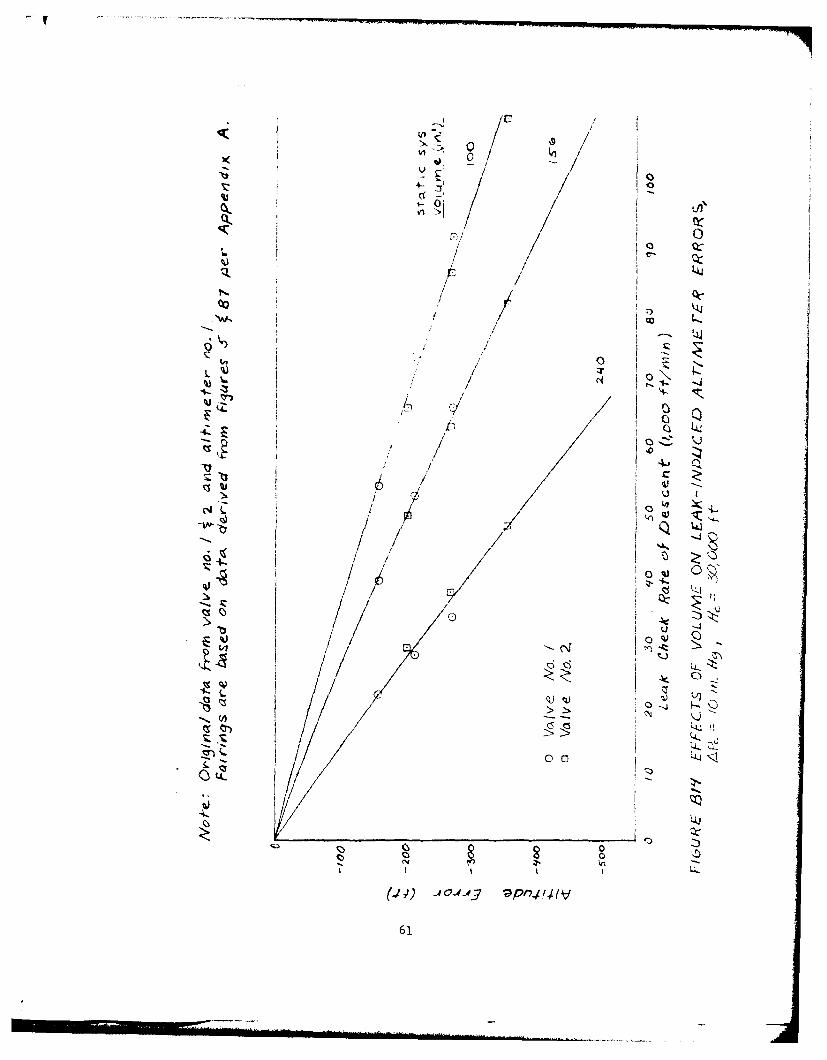
B12-B15 Effects of Volume on Leak-Induced Altimeter 59-62
Errors, APc = 10 in. Hg
B16 Airspeed Errors Due to Static Leaks 63
Appendix C
Cl-CI0 Effect of Leak on Altimeter 65-74
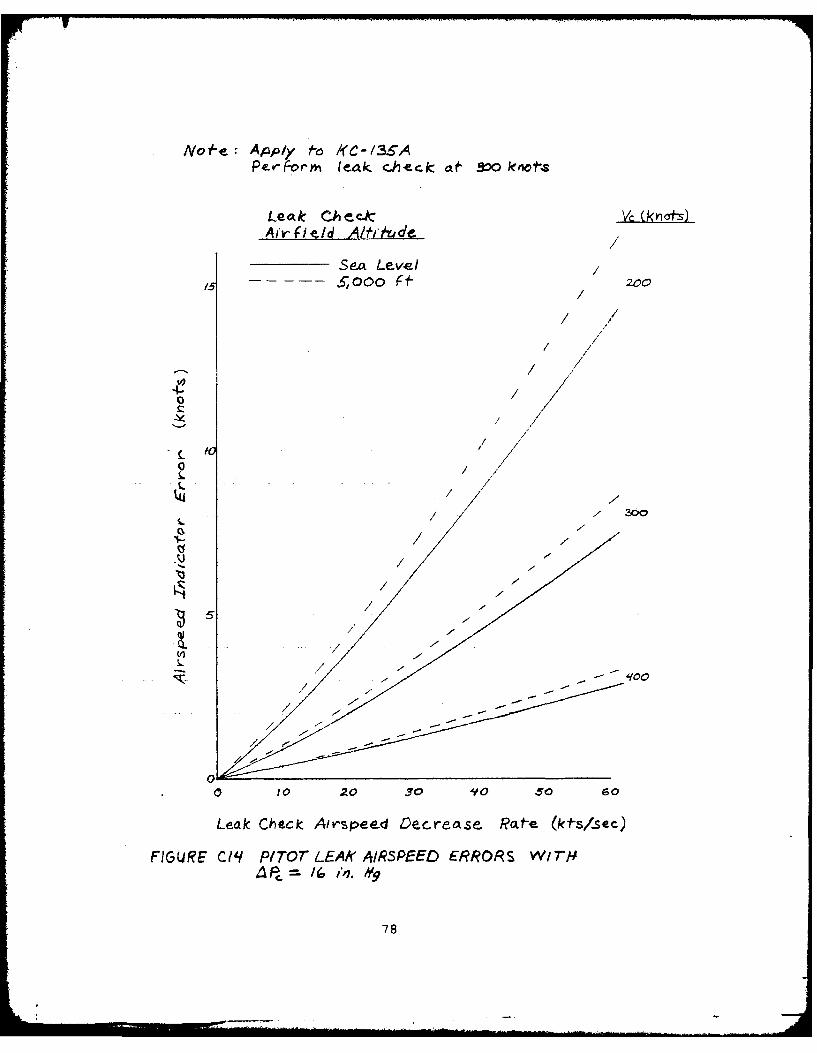
Cll-C14 Pitot Leak Airspeed Error 75-78
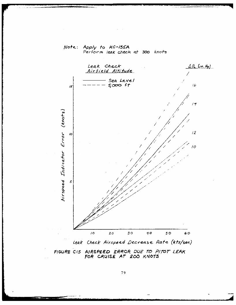
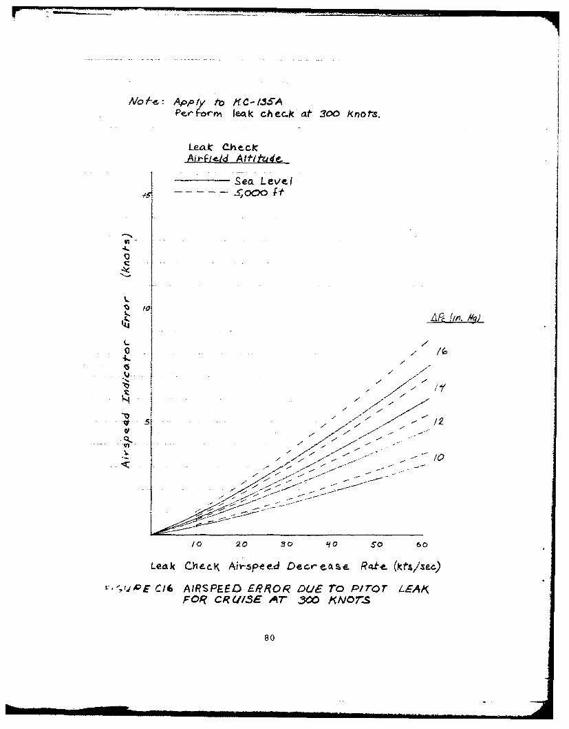
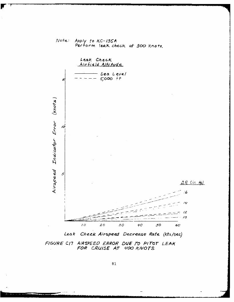
C15-C17 Airspeed Error Due to Pitot Leak 79-81
7
INTRODUCTION
BACKGROUND
A 1966 study (reference 1) determined that the maximum acceptable
error in aircraft altimetry systems should be 4250 feet for flight in
positively controlled airspace with 1000 feet vertical separation
between flight levels. The Department of Defense AIMS program involved
a considerable effort to dete.nine and reduce errors caused by pressure
fields, static sources, computers, and altimeters. During the flight
testing for the AIMS program, it became apparent that there was only
limited knowledge about the errors resulting when leaks existed in
pitot-static systems.
The investigation reported in a 1971 AFFTC Technical Information
Memorandum (reference 2) was conducted to determine the relationship
between leak rates and the corresponding altimeter error for several
in-flight conditions. The tests were conducted on a T-38 aircraft using
the standard 4.8 pounds per square inch (psi) (9.77 inches of mercury
(in. Hg)) cabin pressure differential and various size leak holes. It
was apparent from the test results that a further effort should be made
to completely define the functional relationships affecting leak-induced
pitot-static system errors.
These follow-on tests were conducted as a result of the
recommendation to conduct further testing in a cargo aircraft with a
large pitot-static system volume. The AFFTC possessed NKC-135A aircraft
was considered ideal for the test because of its large airspeed and
altitude envelope and capability to change the cabin differential pres-
sure in an analog manner from 0 to 8.6 psi (17.51 in. Hg).
The test flights were conducted in two phases using NKC-135A air-
craft S/N 55-3135. In tne first phase, eight data collection flights
were conducted using C-19 altimeters as part of the test instrumentation.
Subsequently, a set of Hamilton Standard digital altimeters was installed
on the aircraft. Using the digital altimeters, five data collectionflights were accomplished totalling approximately nine hours. The
results of this report are based on the data collected during the
second series of flights.
OBJECTIVES
The overall program objective was to determine the magnitude ofleak-induced altitude and airspeed errors, using a KC-135A, to aid inestablishing pitot-static system leak rate criteria for AIMS equippedaircraft. Current Air Force leak rate criteria are not related tonor are they based on the resultant in-flight altitude errors. Thedetailed objectives were:
1. To determine static system leak-induced altitude and airspeederrors for various airspeeds, altitudes and cabin differentialpressures.
2. To determine pitot system leak-induced airspeed errors forvarious airspeeds, altitudes, and cabin differential pressures.
3. To investigate the effects of static system volume and leaklocation on leak-induced altitude and airspeed errors. itwas recognized that system confiiuration would affect results.
INSTRUMENTATION
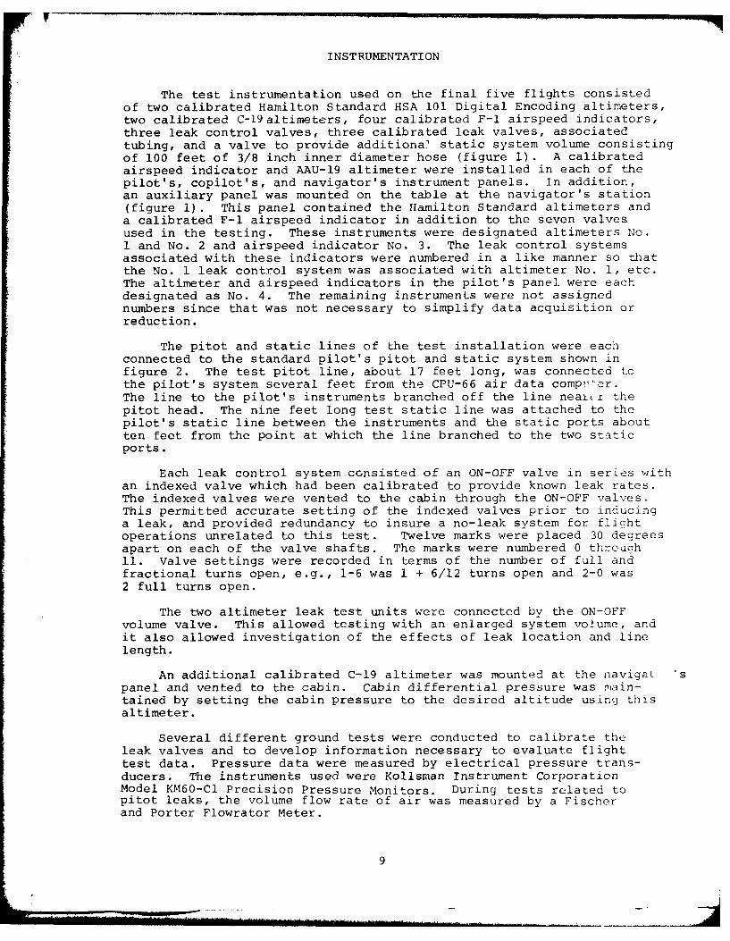
The test instrumentation used on the final five flights consistedof two calibrated Hamilton Standard HSA 101 Digital Encoding altimeters,two calibrated C-19altimeters, four calibrated F-i airspeed indicators,three leak control valves, three calibrated leak valves, associatedtubing, and a valve to provide additiona static system volume consisting
of 100 feet of 3/8 inch inner diameter hose (figure 1) . A calibratedairspeed indicator and AAU-19 altimeter were installed in each of thepilot's, copilot's, and navigator's instrument panels. In addition,an auxiliary panel was mounted on the table at the navigator's station(figure 1). This panel contained the Hamilton Standard altimeters anda calibrated F-1 airspeed indicator in addition to the seven valvesused in the testing. These instruments were designated altimeters No.1 and No. 2 and airspeed indicator No. 3. The leak control systemsassociated with these indicators were numbered in a like manner so thatthe No. 1 leak control system was associated with altimeter No. 1, etc.The altimeter and airspeed indicators in the pilot's panel were eachdesignated as No. 4. The remaining instruments were not assignednumbers since that was not necessary to simplify data acquisition orreduction.
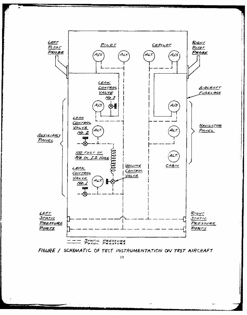
The pitot and static lines of the test installation were eachconnected to the standard pilot's pitot and static system shown infigure 2. The test pitot line, about 17 feet long, was connected tothe pilot's system several feet from the CPU-66 air data compr-er.The line to the pilot's instruments branched off the line nearty the
pitot head. The nine feet long test static line was attached to thepilot's static line between the instruments and the static ports aboutten feet from the point at which the line branched to the two staticports.
Each leak control system consisted of an ON-OFF valve in series withan indexed valve which had been calibrated to provide known leak rates.The indexed valves were vented to the cabin through the ON-OFF valves.This permitted accurate setting of the indexed valves prior to inducinga leak, and provided redundancy to insure a no-leak system for flight
operations unrelated to this test. Twelve marks were placed 30 degreesapart on each of the valve shafts. The marks were numbered 0 through11. Valve settings were recorded in terms of the number of full andfractional turns open, e.g., 1-6 was 1 + 6/12 turns open and 2-0 was2 full turns open.
The two altimeter leak test units were connected by the ON-OFFvolume valve. This allowed testing with an enlarged system volume, andit also allowed investigation of the effects of leak location and linelength.
An additional calibrated C-19 altimeter was mounted at the navigat 'spanel and vented to the cabin. Cabin differential pressure was main-tained by setting the cabin pressure to the desired altitude using thisaltimeter.
Several different ground tests were conducted to calibrate theleak valves and to develop information necessary to evaluate flighttest data. Pressure data were measured by electrical pressure trans-ducers. The instruments used were Kollsman Instrument CorporationModel KM60-Cl Precision Pressure Monitors. During tests related topitot leaks, the volume flow rate of air was measured by a Fischerand Porter Flowrator Meter.
9
LIZ-0r
VA L V- A,41
AVA V& o
/o.1
7-4 C
- - - r/ c- -,e ~5.~
F16URE /SCHEMATIC. OF rEST /'V.SrRUA4EN TATIN ON TEST AIRCRAFT10
AUITOPII 01 MACHCOrN ROLLI H
MARKER BEACON AUTOPILOT PRFSSURESENSITIVITY SWITCH :> I PANSI)UCER
TRUE AIRSPEED -- AUTOPILOT DIFFERFNII AL
COMPUTER PRESSURE CONTROL
TRUE AIRSPEED CONTROLLERINDICATORI
NAVIGATOR'S VGH RECORDER R':
PITOT-SIAT Nj
MANIFOLD - FLIGHI DIRECTOR
If~7?~ ISYSTE M ALTITUDENAVIGATOR'S ~- ~ -CONTROLLERS
COPI LOT'S PITOT.STATICTUBE (TRU-83/A 2)
PITOT AND
STATIC TEST
- STATIC LIN4ES SWITCH :>POTPAE
- PITOT LINES ALTITUDE ELECTRONICS -II
COMPUTER CABINET j
COPILOT AND hNAVIGATOR
PILOT7
13 STA-,IC FOR i
( ,c R e e c e n c e z/K C 1354 AIf Pl A lES 141 TN SFS ;A L A LA tL VSENDING IV I) OR "!
R EC 1 3C AfRPLANES
FGURE 2 D/A6kAM OF P/ror--sT"Ar/c .- SSEfA
0"', TEST AiRqC.AFT
TEST METHODS AND CONDITIONS
GROUND TESTS
Ground testing pertaining to this program consisted of two parts;tests in the laboratory and tests performed on the aircraft. The testinstrumentation was designed to measure the in-flight parameters ccn-sidered to be of primary importance. Prior to the flight tests, itwas postulated that for a given static system an altimeter error dueto a leak would be primarily a function of leak hole size, leak loca-tion, and pressure differential across the hole (essentially cabindifferential pressure if the entire static system is contained in thepressurized portion of the aircraft). Additionally, it was considereddesirable to be able to present the results of the investigation in aformat which could be used directly in a ground check to determine whatin-flight effect a given leak would have. The most direct format isin-flight altimeter error as a function of the static system leak checkrate of descent. It was further postulated that the pressure changein a static system due to a leak would be a function of the leak holesize, pressure differential across the hole, and the system volume.Thus, it was necessary to know the volume of the pitot-static systemson the test aircraft and to know, via calibrations, the effect ofspecified valve settings for each leak valve.
Laboratory Tests:
To determine the effects of volume on the pressure change (rateof descent) due to a leak, several different tank volumes (131, 169,205 in. 3 ) were fabricated and tested. The internal volumes of thesetest tanks were determined by filling each with water several timesand measuring the water volume in a beaker graduated in milliliters.
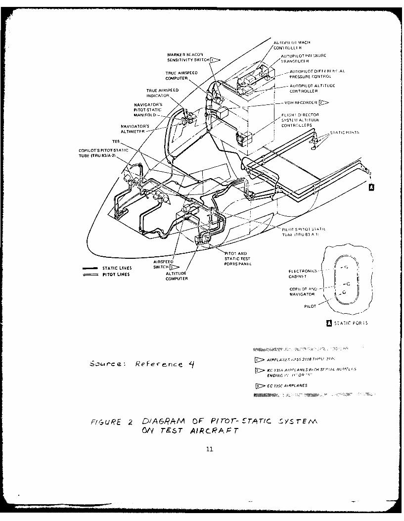
Leak hole sizes (of unknown but presumably repeatable dimensions)were represented by specific settings on the indexed leak valves. Dataconcerning the effects of hole sizes (leak valve settings) and volumewere collected by experiments utilizing the apparatus depicted in figure3. The procedure was to measure the atmospheric pressure using theKollsman Precision Pressure Monitor. Then the test volume was evacuatedto a predetermined pressure and the valve on the pump line was turnedoff. With the leak valve at a particular setting, the ON-OFF valvewas turned on. Pressure readings (in the form of counts) were recordedat five-second intervals by using the display hold feature of thepressure monitor. This procedure was repeated five to seven timesdepending on the proper choice of the initial pressure and the timingaccuracy of data measurements. Each pressure reading was converted topressure altitude by using the Kollsman supplied calibration tables.The data for one such series of tests is shown in figure 4.
Curves faired through the data are nonlinear. Thus, the slope(rate of descent) at any point on a curve is a function of the pressurealtitude (also pressure differential across the valve.. To consistentlyinterpret data obtained on different days, the rate - descent effectof each valve setting and volume was determined at a constant pressuredifferential across the valve. The value chosen was AP = 9.344 in. Hg.This number represents sea level pressure minus the pressure at 10,000feet in the standard atmosphere.
12
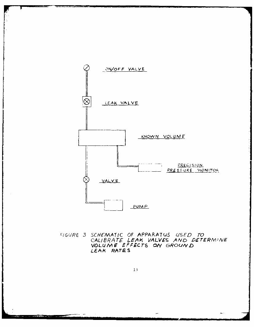
-ON/OFF YALVE
0 LEAK VALVE
K<NOWN VOLUME
PRECIS ION
PRjLJuE* VAONITOR
2LALV E
PUMAP
I:IGL/k 53 SCHEMATIC OF APPARATUJS U/SED roCAL18RATF LEAki VALVES ANzD osrERmi'vEVOLUME E)'PEC7-5 0/y G/?OL/'DLEA A RATE S
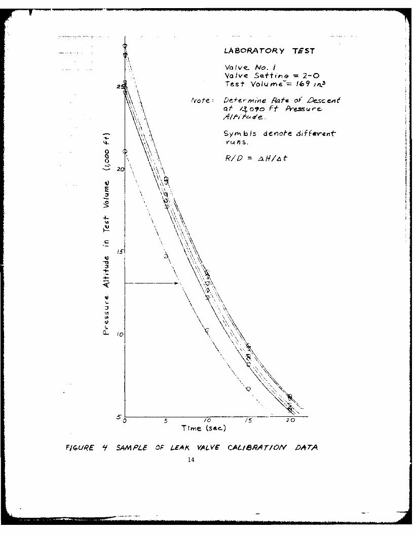
LABc'RArORY TEST
I, Va Ive- No. IValve Seftteio 2-0
2 fxTest Voime- /69 irx3
4teatCM1 n Rate of Z _S~e
RIO/0? ft Pesd20
4-~,ivl eredfeei
5 i Do 2
~14
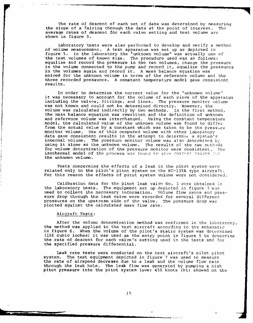
The rate of descent of each set of data was determined by measuringthe slope of a fairing through the data at the point of interest. Theaverage rates of descent for each valve setting and test volume areshown in figure 5.
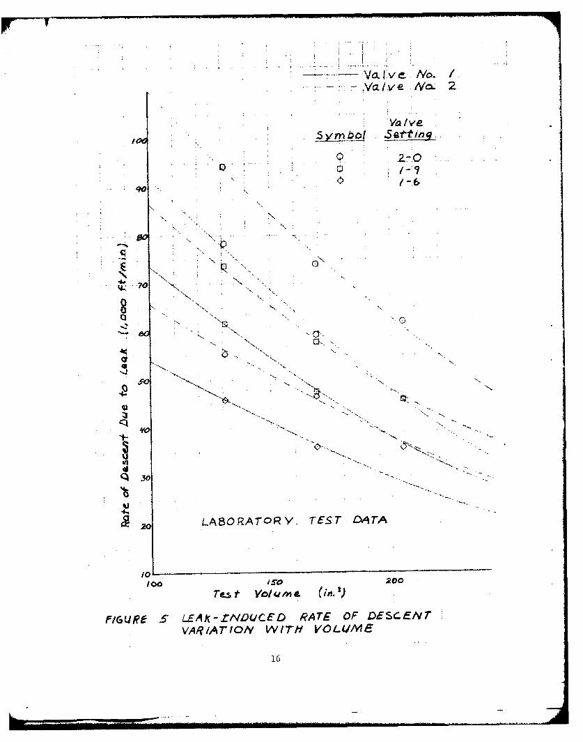
Laboratory tests were also performed to develop and verify a methodof volume measurement. A test apparatus was set up as depicted infigure 5. In the laboratory the "unknown volume" was actually one ofthe test volumes of known size. The procedure used was as follows:equalize and record the pressure in the two volumes, change the pressurein the volume connected to the pump and record it, equalize the pressuresin the volumes again and record it. A mass balance equation wassolved for the unknown volume in terms of the reference volume and thethree recorded pressures. A constant temperature model gave consistentresults.
In order to determine the correct value for the "unknown volume"it was necessary to account for the volume of each piece of the apparatusincluding the valvs, fittings, and lines. The pressure monitor volumewas not known and could not be determined directly. However, thevolume was calculated indirectly by two methods. In the first method,the mass balance equation was rewritten and the definition of unknownand reference volume was interchanged. Using the constant temperaturemodel, the calculated value of the unknown volume was found to differfrom the actual value by a constant which was taken to be the pressuremonitor volume. Use of this computed volume with other laboratorydata gave consistent results in the attempt to determiier a system'sinternal volume. The pressure monitor volume was also determined byusing it alone as the unknown volume. The results of the two methodsfor volume determination of the pressure monitor were consistent. Theisothermal model of the process was found to cive correct values "r,the unknown volume.
Tests concerning the effects of a leak in the pitot system wererelated only to the pilot's pitot system on the KC-135A type aircraft.For this reason the effects of pitot system volume were not considered.
Calibration data for the pitot leak valve No. 3 were obtained inthe laboratory tests. The equipment set up depicted in figure 7 wasused to collect the necessary information. Volume flow rates and pres-sure drop through the leak valve were recorded for several differentpressures on the upstream side of the valve. The pressure drop wasplotted against the calculated mass flow rate.
Aircraft Tests:
After the volume determination method was confirmed in the laboratory,the method was applied to the test aircraft according to the schematicin figure 6. When the volume of the pilot's static system was determined(156 cubic inches) it was used as the entry point in figure 5 to determinethe rate of descent for each valve's setting used in the tests and forthe specified pressure differential.
Leak rate tests were conducted on the test aircraft's pilot pitotsystem. The test equipment depicted in figure 7 was used to measurethe rate of airspeed decrease due to a leak and the volume flow ratethrough the leak hole. The leak flow was generated by pumping a highpitot pressure into the pitot system (over 450 knots (kt) showed on the
15
Va.tve_ Nc. /Iva .V v e ../'-2
- lve No.2
5ymb( Sal
90
'.. / -.
K N
~70 K
_ -- AT ,.,. TEST .,.
c "-.0 . - -
- N "
IOOIS$O 200
FIGURE. 5" L.EAX- ZNUCEDL RATE OF DiESC-E/vrVARIATION WITH VOLUME
16
UJNKNfOWN VOLUME
(AIRCRAFT STATIC SYSTEM)
VA LV E
REFERENCE VOLUM E
-- RE J r-Cts ION
VALVE -~PRESSURE MON'p~
FIGUIRE 6 SCHEMATIC OF APPAPATJs usEDO ro
DETERMINE AN UINKNOWN VOLUM~vE
17
'p N-7 q
Ia I) v
L ABC) RATO R Y 7ESTS
i EAbN FLO W
I~V 1 UA C6 4P
AIRCRAFT SYSTEMSHa,'s
AIRCRAFT- T-E!TS
F(GuRE 7SCHEMA71CS OF EQPL4P&IENT USED
FOR~ Piror i.EAt 6PcCJND r-ESTS
18
airspeed indicator) and setting the pump at a low pitot pressure (50 kt)during the leak test. The rate of airspeed decrease measured on thepilot's airspeed indicator was plotted against the calculated mass flowrate.
Ground tests pertaining to pitot leaks were not repeated or dupli-cated. Thus, there was no obvious indication of repeatability or scatterin the measured parameters for any given conditions.
The pilot's and copilot's pitot-static systems were leak checkedand leaks were eliminated until the leak criteria established for thisproject were achieved. The leak criteria for the pilot's pitot-staticsystem was zero leak rate. The copilot's pitot-static system leakswere no greater than 50 feet per minute decrease in indicated altitudefrom 10,000 feet and 3 knots increase in airspeed in 5 minutes from 300knots indicated when the pitot and static systems were pressurized tothose starting values using a TTU-205 pressure test set.
FLIGHT TESTS
The flight test method used was termed no leak/leak in reference2. With the aircraft stabilized at a specified speed and altitude onthe copilot's instruments, instrument readings were recorded with theleak control valve off. Then the instrument readings were again recordedwith one of the leak control valves on and the associated indexed leakvalve set to a specified opening.
Leaks into the pitot and static systems were always made from theaircraft cabin with the cabin pressure higher than ambient. No attemptwas made to leak out of a system into a compartment with pressure lessthan ambient.
Pneumatic altimeters were used for the first eight test flights.Analysis indicated that the data contained too much scatter to demon-strate the desired repeatability and expected trends. The ro'eclri'alHamilton Standard altimeters installed for the final five test flightspresented a combination digital and discrete clock-face readout. Theresolution of the clock-face presentation was 20 feet. Thus eachmeasurement of the basic altitude data contained an uncertainty of 10feet.
None of the airspeed indicators were replaced by pressure transducers.All airspeed error data was measured by the calibrated pneumatic air-speed indicators.
On the first leak test flight with pneumatic instruments, leakvalve settings of 0-9, 1-0, and 1-3 were tested. However, the altim-eter error magnitudes were not large enough to sho-w trends. Scatterin the reduced data was too large. On the second leak test flight,settings of 1-6, 1-9, and 2-0 were used. This increased error magni-tudes enough that some expected relationships were identifiable. iow-ever, these settings produced ground leak check rates of descent of12,000 to 19,000 ft/min for valve No. 1 with the altimeter reading10,000 feet and an airfield altitude of 2,300 feet =.,P 6.94 in. fig.).The ground check leak rates were measured with the test instrumentation,including the additional tubing volume, installed. The test instru-mentation approximately doubled the static system volume and thus sig-nificantly lowered the indicated rate of descent due to the leak. When
19
the digital altimeters were installed, flight tests continued using thelarger leak holes. No tests were performed with smaller leak holesgiving leak rates closer to the currently accepted leak rates.
During the first flight ten sets of data were recorded for eachparameter of interest. With each succeeding flight the number ofrepetitions was reduced. Three sets of data were recorded for eachparameter value on the last flight.
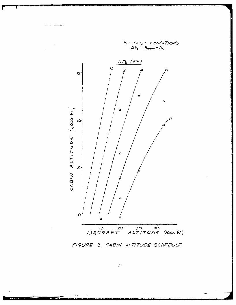
During the test it was confirmed that the primary parametersaffecting altimeter error for a given system were leak size, leak loca-tion, and cabin differential pressure, APc. Cabin pressure was recordedby the extra altimeter at the navigator's panel. The pressure differ-ential conditions used on the last series of flights are shown onfigure 8.
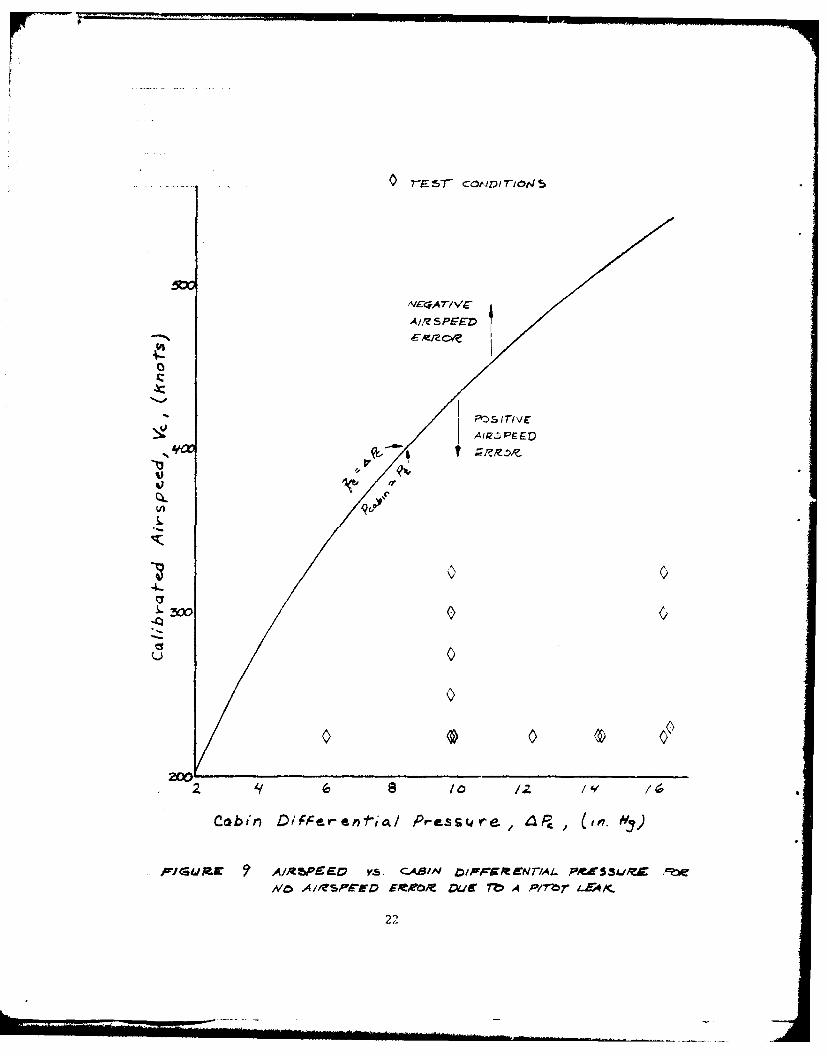
Airspeed data were recorded for the conditions of no leak and leakthrough the static and total system leak valves. The primary parametersaffecting airspeed errors due to a pitot system leak were leak size,airspeed, and cabin differential pressure. A leak-induced airspeedindicator error is caused by a pitot pressure error at the indicator.The pressure error is due to pressure loss mechanisms affecting theleak flow (system geometry and viscosity) and the relative locationsof the leak and the indicator. When there is no leak flow, there canbe no pressure error. Thus if the pitot (total) pressure equals thecabin pressure, there will be no flow through the hole and no errorsignal. Another representation of the same conditioi. is that whenimpact pressure, qc, (total minus static) equals cabin differentialpressure. ',Pc, (cabin minus static), there will be no error. Figure9 s LW3 Uie relationship of airspeed to cabin pressure differential foiwhic9h there will be no airspeed error with a hole in the pitot system.Thc nil-ot leak test conditions are also indicated.
20
A - TEST CoNV/T/oN~L~P~ .~Pa
~ (psi.)
4
/ / //
/I/ A
1-' IL4
0 /1 / 5
/1/ ii /
o / Ii I1/ /
IAIi
-J
- I /I //
o // A!
/
0/ A
10 20 30 40AI/~'CRAFT A4T/7Qc~6 (/ooo~)
FIG L/R~ B CAB/N ALT/7b/Dt SCHEDL/W
-I,
A//? S FED
4-
00
Cai D4CeO-tit PrTI\I(e_4P
, FPUAK l~rWEEO .S. ABI DAIrrOMED17W flC3 6
Iv A1ESPrD OWR U~ AP/brLEC
A 9 22
TEST RESULTS
Analysis of data from the first series of flight tests ha, inclicatethat there was no definitive dependence of altimeter error upon varyingairspeeds. After the installation of the digital altimeters, the firsttest flight again explored the effects of airspeed on the altimeter errors.The data (figure B1) indicated that increasing the airspeed caused aslight increase in the altimeter error. However, the effect was netconsidered significant enough to include airspeed investigation orsubsequent flights most of which were flown at 225 kt indicated air-speed.
The static pressure error due to a leak increased with increasingMach number (figure B2) . Only the data from one flight was acquire,1cat constant altitude (30,000 ft) and varying airspeed. The Mach nuri rvariation of the other data is due mainly to altitude variation. Inaddition to the pressure error variation with Mach number-, four pairsof data points (see 43,000 feet data) indicate that the pressure erroralso increased with increasing flight altitude.
The mechanism for the pressure error increase was probably relatedto the variation of true airspeed (figure B3) . The leak air flowinqout the static ports probably disturbed the boundary layer, and possiblythe free stream, flow pattern near the ports. The external flow distur-bance probably caused a pressure increase at the static ports. Ingeneral, the boundary layer thickness at a point on a surface is inverselyproportional to the square root or fifth root of the free stream velocitydepending on whether the boundary layer is laminar or turbulent. In-creasing airspeed, through boundary layer thinning or some other mechanis,may cause a pressure increase at the static ports so that the pressureerror at the altimeter increases with airspeed.
The average altimeter error at each test point was converted tostatic pressure error. The static pressure error data is shown plotteiagainst cabin differential pressure (P c ) in figure B4 throuch fiureB6. The fairings shown are linear regressions through all the data.With few exceptions the data show that the pressure error increasedwith increasing flight altitude for any cabin differential pressure.
Pihlgren (reference 2) found no static pressure error relationwith changing flight altitude for fixed 'PC conditions. Pressure datashowed some scatter but no altitude correlation. The different rcsultsof this study may result from the use of more sensitive instrirmenta'-ionor from the different pitot-static sources used on the two test aircralt.
Certainly, part of the pressure error increase with altitudc re-suited from the increase in true airspeed. However, there are prolablyother effects involved since the altitude parameter appeared in fl{eure132 and figure B3.
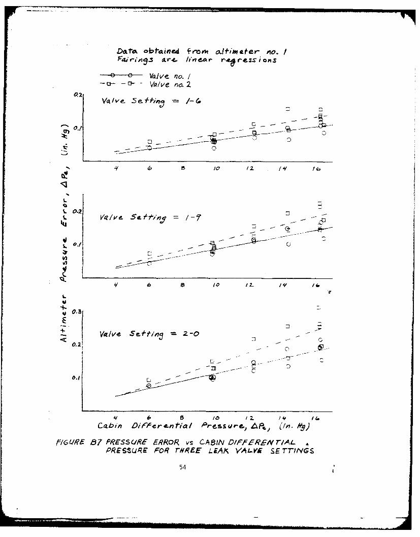
The effects of leaks through valves No. 1 and No. 2 measured ataltimeter No. 1 are compared on figure B7. The linear fairings wer-eused to extract the data necessary to produce the final results inthis report for the KC-135A aircraft. Due to insufficient data anlthe scatter in the data available, data from each test altitude w,;renot faired nor were individual fairings used to produce the finalresults. The figure B7 plots show that leaks through valve No. 2
23
produced larger static pressure errors. The reason for the differenteffects was that valve No. 2 created a larger hole than valve No. Ifor any given valve setting (number of turns open). The larger holesize allowed a greater flow rate through the static system (figure 5).Additionally, it was assumed that pressure drop in the static systemand flow rate through the line were linearly related. For that reasonit was felt that the altimeter No. 1 data for valves No. 1 and No. 2could be correlated.
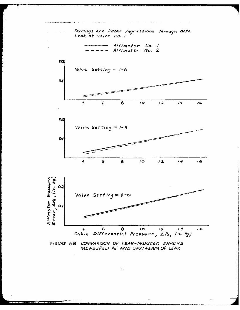
The fairings through the altimeter No. 1 and No. 2 data for leaksthrough valve No. 1 are compared in figure B8. The data showed that thepressure in a part of the static system upstream from the leak locationwould reach the same pressure as that at the leak location. The upstreamlocation is a part of the system through which there is no leak airflow.
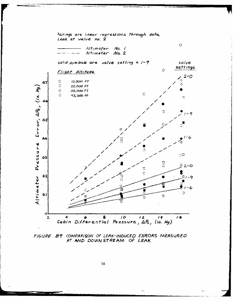
The data and appropriate fairings for measurements at altimetersNo. 1 and No. 2 with leaks through valve No. 2 are compared in figureB9. The difference between the pressures at the two altimeters is dueto the pressure losses caused by the viscous resistance to the flowthrough the 100 feet of static line between the two altimeters.
Figure B9 shows that a leak at the altimeter case would cause agreater error than a leak at a location upstream which would cause flowthrough the line past the junction to the altimeter. A similar sizedleak hole at a downstream location between the altimeter and the staticports would cause less error than if that leak occurred at the altimeter.Less pressure error would be transmitted to the altimeter because theshorter tubing length between the leak and the outlet would cause lessviscous pressure loss. Thus, a leak at the altimeter can be expectedto cause the greatest altimeter error.
The methods discussed in Appendix A and shown in figure Al andfigure A2 were used to create plots of altimeter errors for the parametersof significance in a production static system. Quadratic curves werefit through the data and the origin using a least squares routine tocompute the coefficients of the equations. Examples of the deriveddata points and the quadratic fairings are shown in figure B10 andfigure Bll. The results pertain to leaks in the KC-135A pilot's staticsystem.
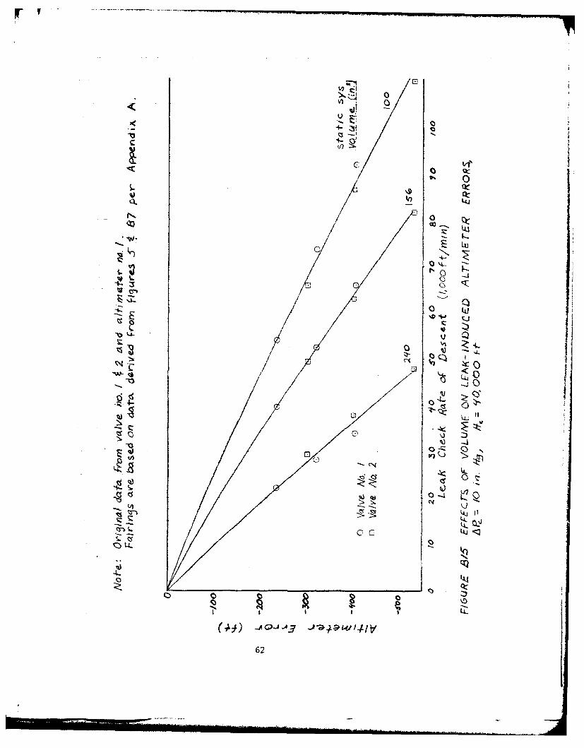
Effects of different static system volume are shown in figure B12through figure B15. The curves represent only the effect that systemvolume has on the leak check rate of descent. System configurationeffects were not included. Since all the altimeter error values arebased on the KC-135A tests, a different system configuration, withthe same volume, could give different results; for example, a con-figuration causing greater resistance to leak flow (long static lines,smaller lines, or smaller static orifices) would create greater leak-induced altimeter errors. The curves were hand faired through datapoints derived as previously discussed. The 100 cubic inch value waschosen arbitrarily. The 156 cubic inch value represents the pilot'sstatic system in the KC-135A. The 240 cubic inch value represents theproduction static system in the RF-4C aircraft. In support of a studyof the sensitivity of the pitot-static systems on the AFFTC pacers, thevolumes of the pitot-static systems on the RF-4C pacer were determinedusing the methods previously described. The production system volumewas estimated by subtracting the estimated volume of the pressuretransducer connected to it.
24
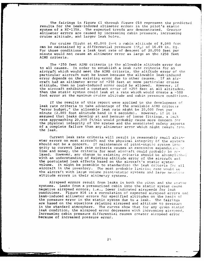
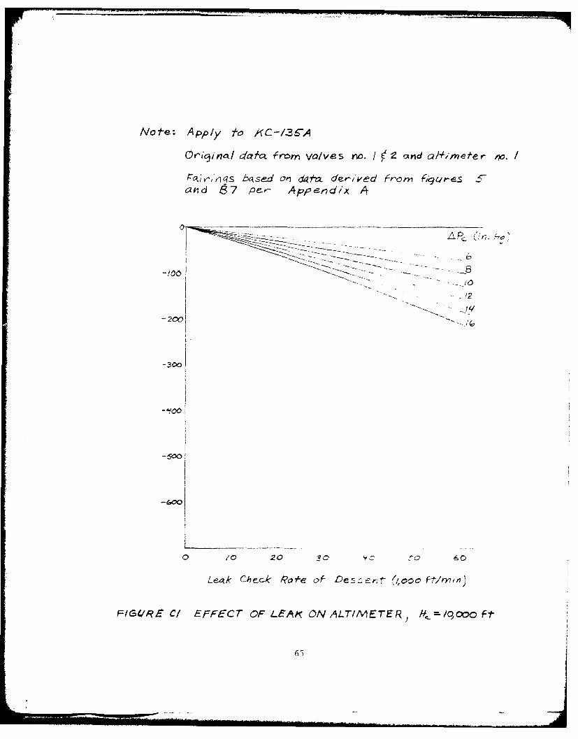
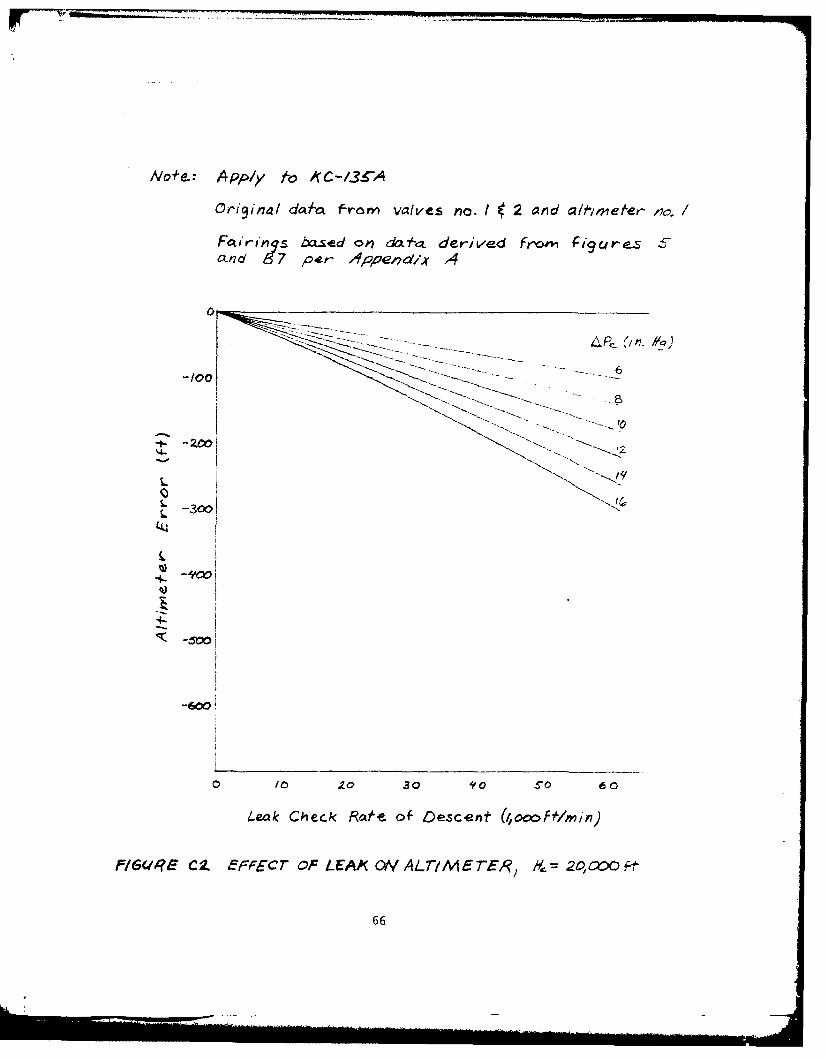
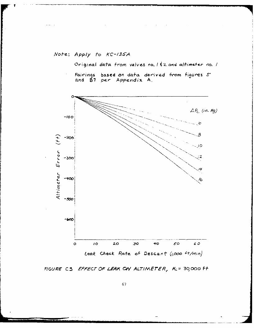
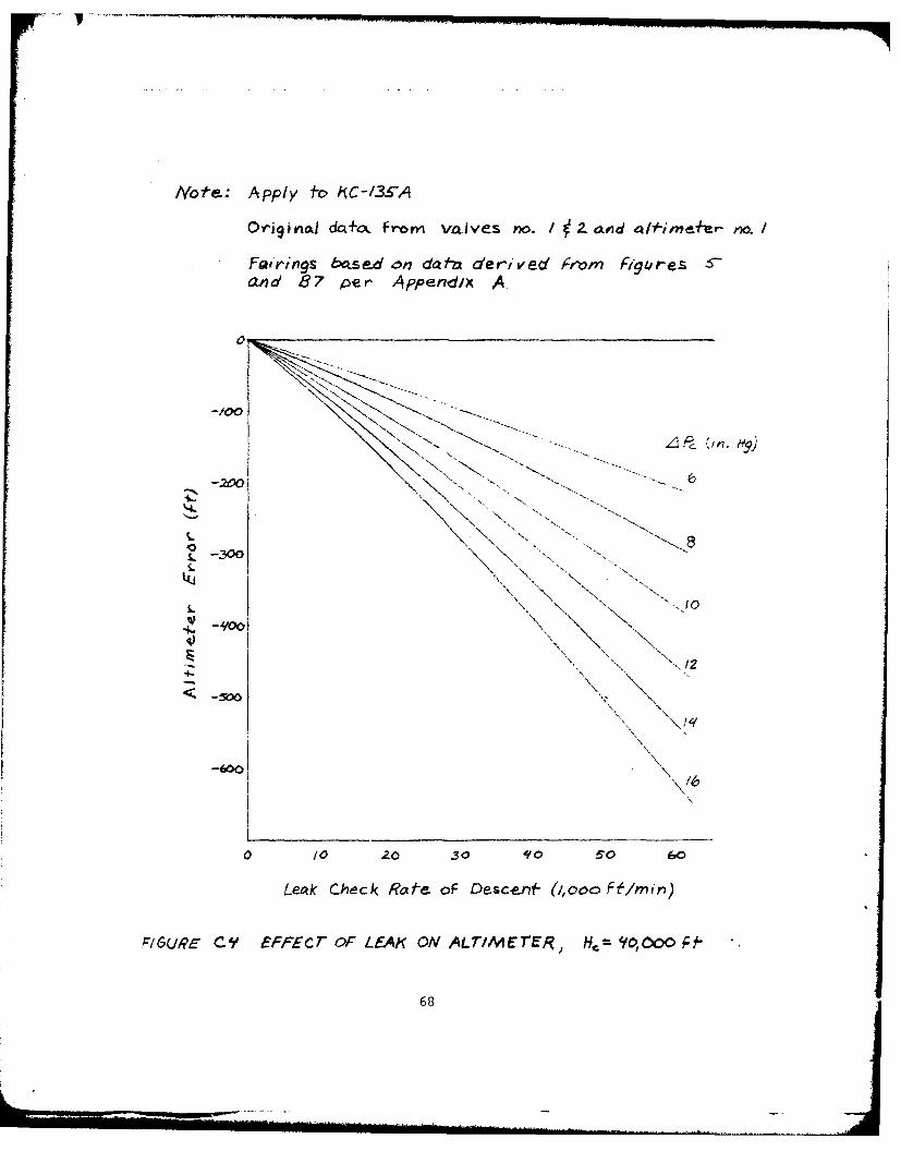
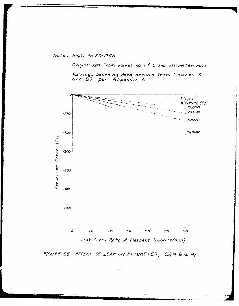
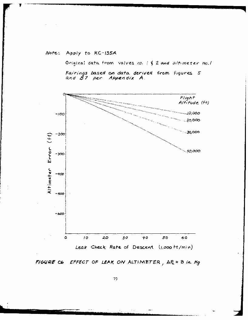
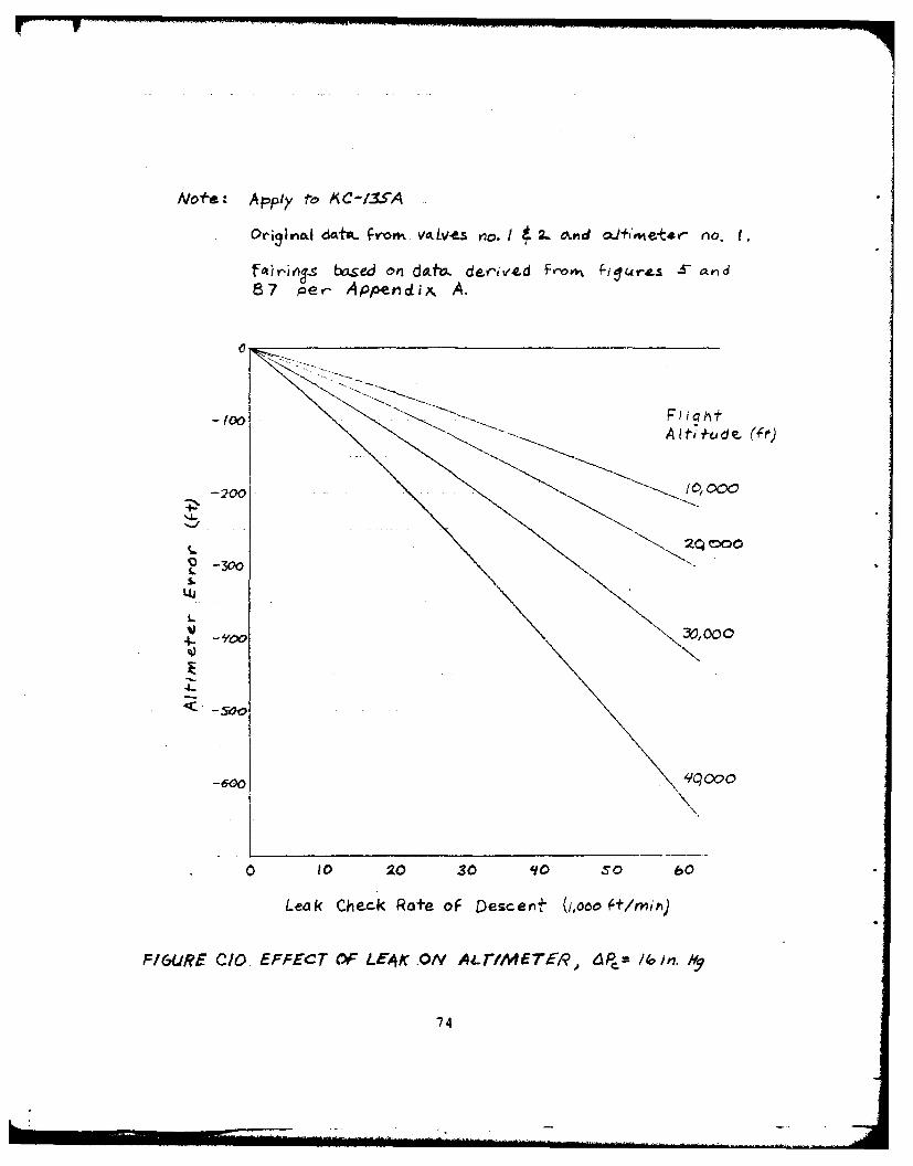
The fairings in figure Cl through figure C10 represent the predictedresults for the leak-induced altimeter errors in the pilot's staticsystem of a KC-135A. The expected trends are demonstrated. Greateraltimeter errors are caused by increasing cabin pressure, increasingcruise altitude, and larger leak holes.
For cruise flight at 40,000 feet a cabin altitude of 8,000 feetcan be maintained by a differential pressure (APc) of 16.69 in. Hg.For those conditions a leak test rate of descent of 20,000 feet perminute would not cause an altimeter error as large as the ±250 feetAIMS criteria.
The ±250 feet AIMS criteria is the allowable altitude error dueto all causes. In order to establish a leak rate criteria for anaircraft which would meet the AIMS criteria, the altitude error of theparticular aircraft must be known because the allowable leak-inducederror depends on the existing error due to other causes. If an air-craft had an altimeter error of -250 feet at some particular cruisealtitude, then no leak-induced error could be allowed. However, ifthe aircraft exhibited a constant error of +250 feet at all altitudes,then the static system could leak at a rate which would create a -500foot error at the maximum cruise altitude and cabin pressure conditions.
If the results of this report were applied to the development ofleak rate criteria to take advantage of the available AIMS criterla"error budget," the allowable leak rate might be 20,000 feet perminute (2,000 foot altitude band in 6 seconds). However, if it isassumed that leaks develop at and because of loose fittings, a ie-krate approaching 20,000 ft/min would probably cause more concern forthe physical integrity of the system and the associated safety aspectsof a complete failure than any altimeter error which might result fror.the leak.
Current leak rate criteria will result in reasonably small altim-eter errors on most aircraft and the physical integrity of the syste:'sshould not be a concern. If maintenance of pitot-static system int-o--grity to current leak rate criteria causes an excessive expenditji- :,1time and money, the criteria for most aircraft could probably be rt-laxed. However, any change to existing criteria should be accomlihc:K, .with an understanding of existing altitude error of the aircraft andthe postulated leak effects based on the aircraft's static systenvolume. It might be possible to standardize the leak criteria for allaircraft in the inventory. The most probable limitinq case would bethe aircraft with large volume pitot-static systems and large ne.v 1vc',altitude errors in their altimetry systems.
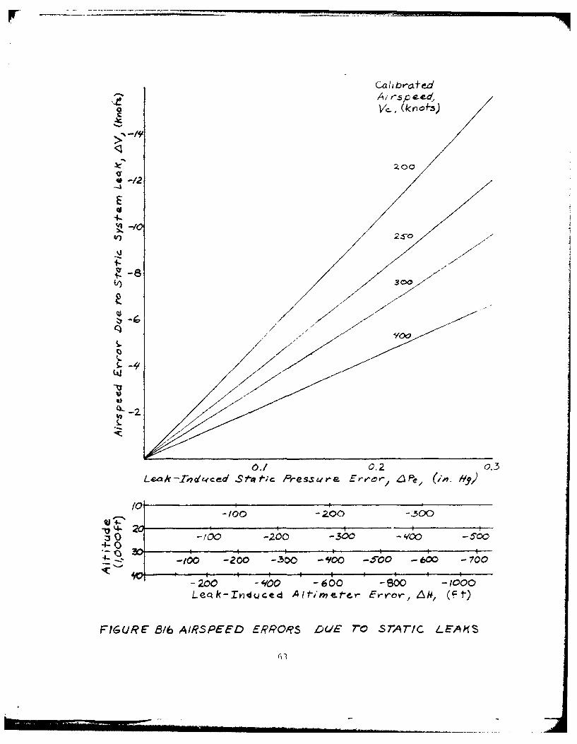
Airspeed errors result from leaks in both the pitot and the staticsystems. Leaks from a pressurized cabin into the static system causenegative airspeed errors, i.e., lower indicated airspeeds for leakconditions. Figure B16 is a correlation of expected airspeed errors andleak-induced altimeter errors for specified altitudes on the basis ofthe pressure error in the static system due to a leak. The fairingsare based on the equations relating airspeed and altitude to pressurein the standard atmosphere. The curves show that for any given staticleak condition, the airspeed error decreases with increasing airspeed.Increasing cabin pressure differential causes creater airspeed errorbecause of increased pressure error.
25
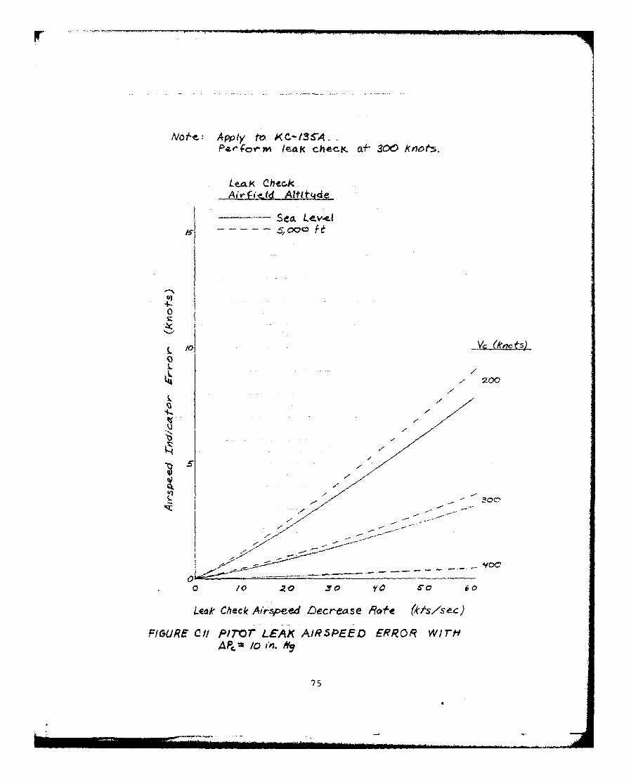
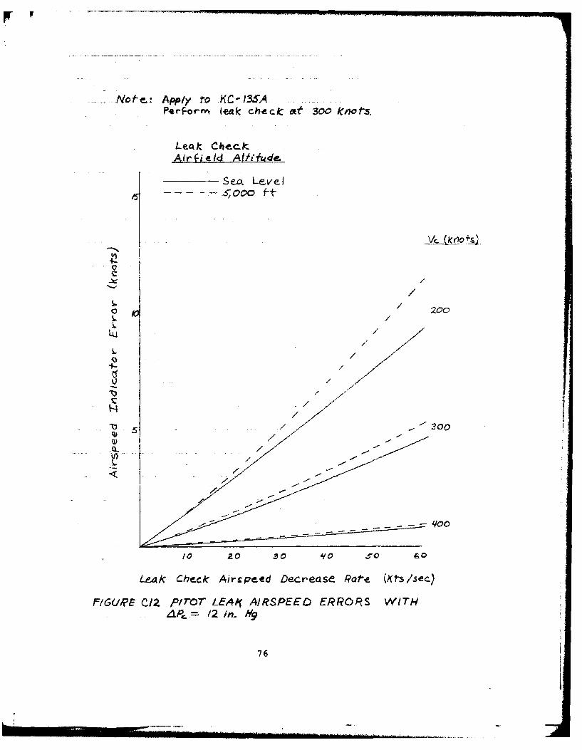
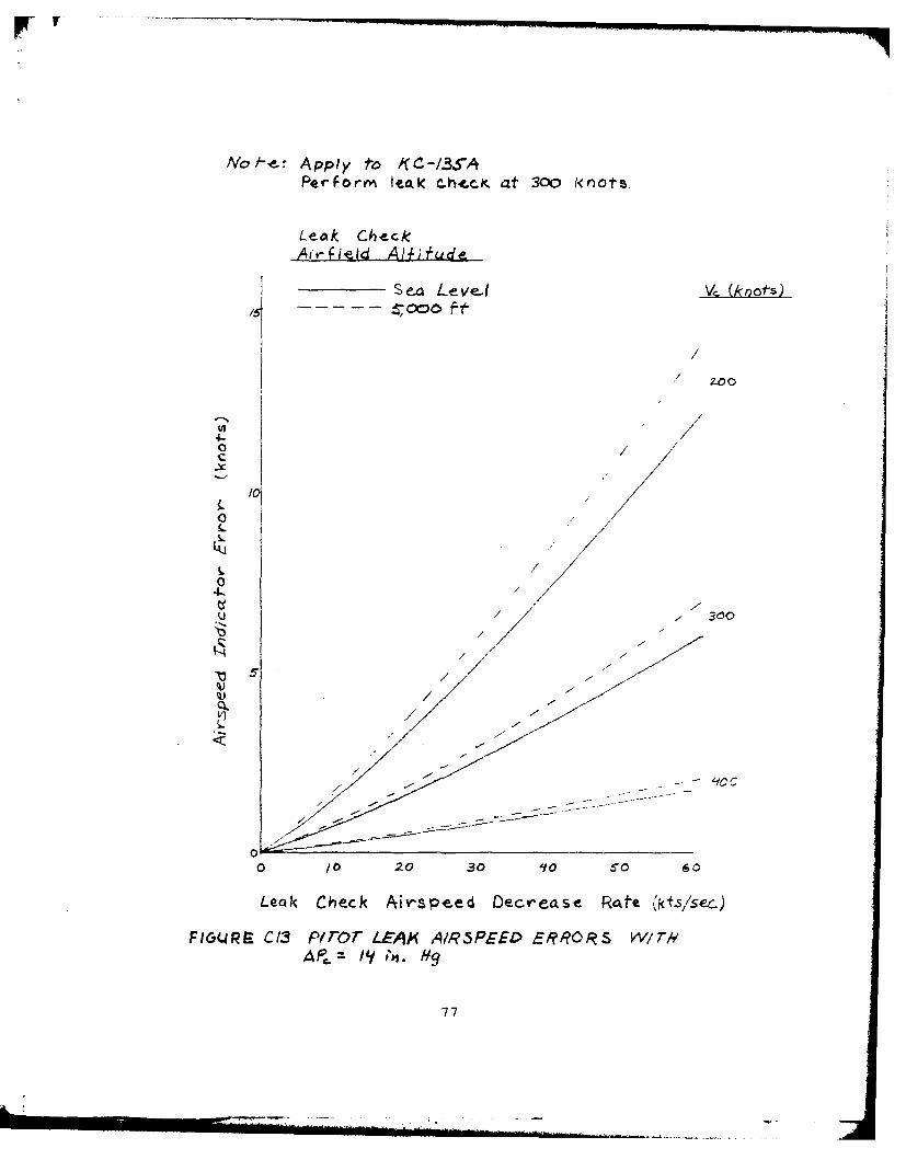
Pitot system leaks cause airspeed errors which depend both on air-speed and cabin pressure differential. The airspeed effect on airspeederrors for particular cabin pressure differentials is shown in figureClI through figure C14. The plots apply to the KC-135A pilot's airspeedindicator. Increasing airspeed and decreasing hole size caused decreasingairspeed errors for any given cabin differential pressure. The figuresalso show the effects of varying the airfield altitude at which the leakcheck is performed.
The cabin pressure differential effect on airspeed errors forcertain airspeeds is shown in figure C15 through figure C17. Thoseplots also apply to the KC-135A pilot's system. The fairings show thatincreasing cabin differential pressure causes increased airspeed errorsfor given airspeed.
Variables such as leak location and system volume were not inves-tigated in the pitot leak tests. However, effects similar to thoseshown for the static leak investigation (figure B8 and figure B9) wouldprobably occur. A leak in the airspeed indicator fittings would probablycause the greatest errors. The leak check airspeed decrease rate wouldbe higher for a smaller volume pitot system if the leak hole and testconditions were similar.
26
CONCLUSIONS AND RECOMMENDATIONS
The major variables affecting altimeter errors due to static systemleaks were leak hole size and the difference between cabin and ambientpressure. Airspeed errors were affected by the same variables as wellas airspeed. Ground test leak rate was found to depend on leak holesize, system volume, and the pressure differential at which the testwas conducted.
In general, the leak effects tests showed that small pitot-staticleaks do not result in significant altitude or airspeed errors. Signi-ficant errors can result as the leak rate increases to levels at leastan order of magnitude greater than current leak rate criteria willallow. A static pressure system leak check criteria based solely onpermissible altitude error might allow leaks which are unacceptablylarge when system integrity is considered. The continued use ofcurrent Air Force pitot-static system leak check criteria should resultin negligible airspeed and altitude errors. The leak rate criteriafor any aircraft could probably be relaxed if maintenance man-hoursexpended to stop leaks were found to be excessive. Adjustments couldalso be made in the interest of standardizing leak check criteria forall Air Force aircraft. Any changes to the present procedures mustconsider that the allowance for leak-induced altitude errors dependson the existing altitude error curves for static system installationsas they relate to the AIMS criteria.
i. Current Air Force leak rate criteria should bemaintained.
2. Leak rate criteria for new aircraft and changes tothe current criteria used for Air Force aircraftshould be based on the aircraft's altitude errorcurve, its relation to the AIMS criteria, and theeffect that the static system volume will have onthe relationship between the leak rate criteriaand the expected altitude error.
27
REFERENCES
1. Marshall, Philip R., USAF Improved Altimetry Systems, SystemsEngineering Group, Wright-Patterson AFB, Ohio, 1966.
2. Pihlgren, Wayne D., Effect of Static System Leakage on AircraftAltitude Measurements, FTC-TIM-71-1005, Flight Test TechnologyBranch, Edwards AFB, California, 1971.
3. Pitot and Static Pressure Systems, Installation and Inspection of,MIL-P-26292C (USAF), 3 December 1969.
4. Technical Manual, General Airplane, USAF Series KC-135A, EC-135C,RC-135C Aircraft, T.O. IC-135(K)A-1, 15 February 1964.
28
APPENDIX A
DATA ANALYSIS METHODS
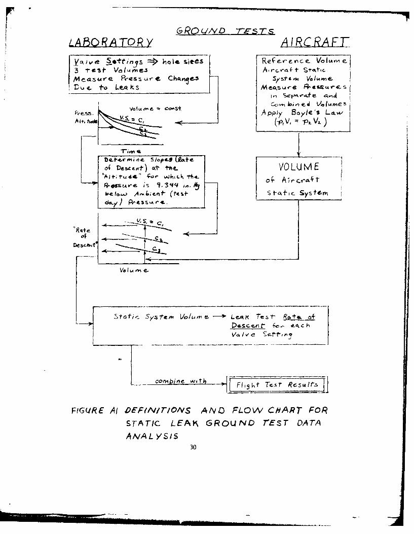
Due to the original desire to produce a generalized model of leak-induced altimeter errors which could later be applied to any aircrafttype, a number of ground tests were performed which might not have beennecessary to define the static system leak effects on just the KC-135Aaircraft type. Depicted in figure Al is the process by which datacollected in the laboratory and during aircraft ground tests were corre-lated to produce generalized effects and unique values of the principalparameters (figure 5) characteristic of ground leak checks.
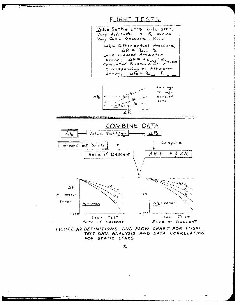
Flight test data used to generate the final altimeter error resultspresented in this report consisted of instrument corrected pressurealtitudes for no leak and leak conditions and the associated cabinpressure altitudes. The altimeter readings were converted to pressures(figure A2). From each set of altimeter data the equivalent pressuredifferential was computed, i.e., cabin differential pressure,APc = Pcabin - Pa, and leak-induced altimeter pressure error, APePic leak - Pic no leak. The computed pressure errors were then plottedagainst the associated cabin differential pressures (figure A2). Datafor the final plots were obtained from the fairings through the pressureerror plots.
The predicted altimeter errors for the KC-135A aircraft type shownin this study were generated by combining the results of the ground andflight tests (figureA2 ). Cabin differential pressure, APc, was one ofthe significant parameters. A value of altimeter pressure error, !Pc,was obtained for each valve setting and the selected APc value from thefairings through the measured data. Each valve setting was convertedto a leak check rate of descent by way of the ground test calibrations.Each pressure error was converted back to a series of altimeter errors,one for each specified cruise altitude, by using the equations for thestandard atmosphere or tabular data of same. Thus, the final plots ofaltimeter error as a function of leak check rate of descent could beplotted for the parameters of cruise altitude and cabin differentialpressure.
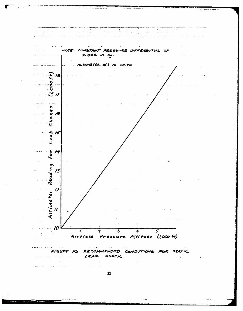
The data resulting from ground tests on the leak valves and testvolumes was correlated by using a fixed pressure differential betweenambient pressure and pressure inside the test volume. To extend themethods and results of this program to a leak check on a KC-135 aircraftat some other location the check should simulate the conditions (primarilypressure differential) used to obtain the test data. Rather than evacuatethe static system to an indicated pressure altitude of 10,000 feet, thestatic system should be evacuated so that the leak check can be accom-plished at an indicated pressure altitude corresponding to a pressuredifferential of 9.344 in. Hg. Figure A3 shows the schedule which shouldbe followed to maintain this pressure differential. For an airfieldpressure altitude of 2,300 feet, for example, the leak check should beaccomplished at an indicated pressure altitude of 13,150 feet (usingan altimeter setting of 29.92).
The airspeed errors recorded for static system leaks were not usedto develop a model for predictions of these errors for any arbitraryleak. Instead the equations relating pressures to calibrated airspeed
29
LA80 R ATOP>R A I CAEL
Y~v S *-tinys 4 a~ sit £e.5 I Ref e- c e rr-e- Vo 1,4v, -3 test V.M~Iie.5 Ar-,raft Stttoc
Me a5 wAVe Press 4-r Cha~re-3 S*mVai0e~
Lu fto Le k~s M eoo Arue Pe c-1 .1 Set-% -4.t e 4.%4
AoW pplyS Boyle's LaA (t. h~de v- C,(_P, V, = _2 a
T-im 4L Wbe*4r.C I Ae SopS(ie-1
0 Desceot) Ott the- VOLUME1,e u~e 4 OLq , - .
OsS u -e-X
Loele. 14eIbt4f (t___ _____ _S i__ ____ _____ _____ ____
Static -System~ voloe L cAt hstfot of
FIGURfE A( DE~~vrN/TIOS AIY D FLOW CH'ART FOR
STATIC LEAKS GROUND rEST DATAANAL YS/S
30
FLIGH-T TESL~a
va.-7v A I h. t e \ka Pv- esaVo-/Ck-bv ReSCA' PMPcq.,
Lea-Z,j,4ee4 At#imwefe--Ecwcv-r, J1 A' 14;c l, - 44
Cor PAted Prezsck4Ye- Frrov--
Cov-cespovdv1 +o A I-ite-
AP - Re de.-fo - ve 4. *
-f.o r. d~t&
r~ ePr Icv ve
- --- ---
Descent~ Ai 0
Cc?
R tp of Descenit P~.te Of ~eC-en
FIGURiE A2 DEFINI1TIONS5 AND P1LOW C,'7ART Foi$q FL/16HT
TEST DATA ANALYSIS *IVO DArA CORE-LAr/O//FOR~ STATIC LEAKS
31
AdO7~rt cO"SrA#r ACgE U& OldJ WKEA171 OF
- -~~~~ - 3rM~~ 44A -Y7
0lrt~f -rA'ApY
-A
V
0
'32
and pressure altitude were used to relate airspeed errors to altimetererrors for particular pressure errors, airspeeds, and altitudes.
Tests to determine the effects of leaks in the pitot system weredesigned to apply specifically to the pilot's pitot system on the KC-135Aaircraft. Tests to establish a generalized model ba3ed on system volumewere not conducted.
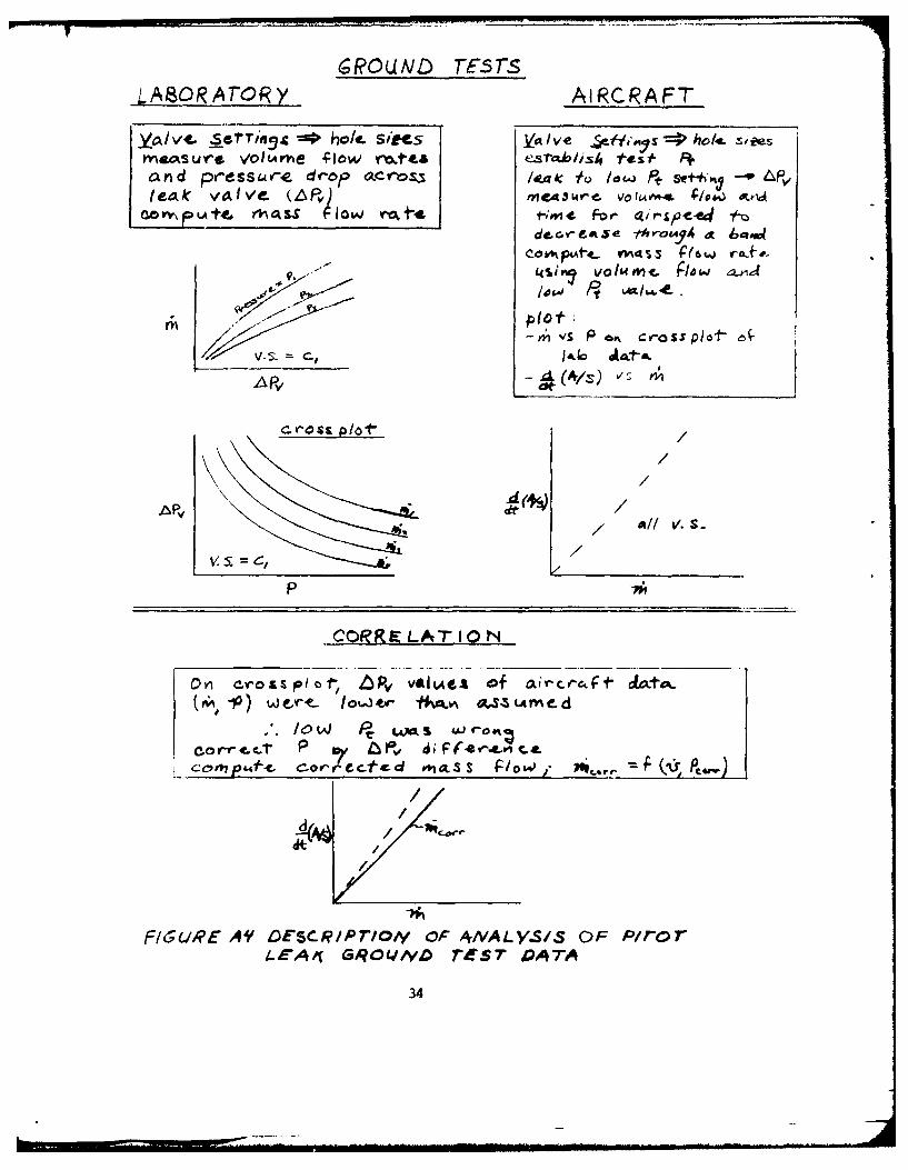
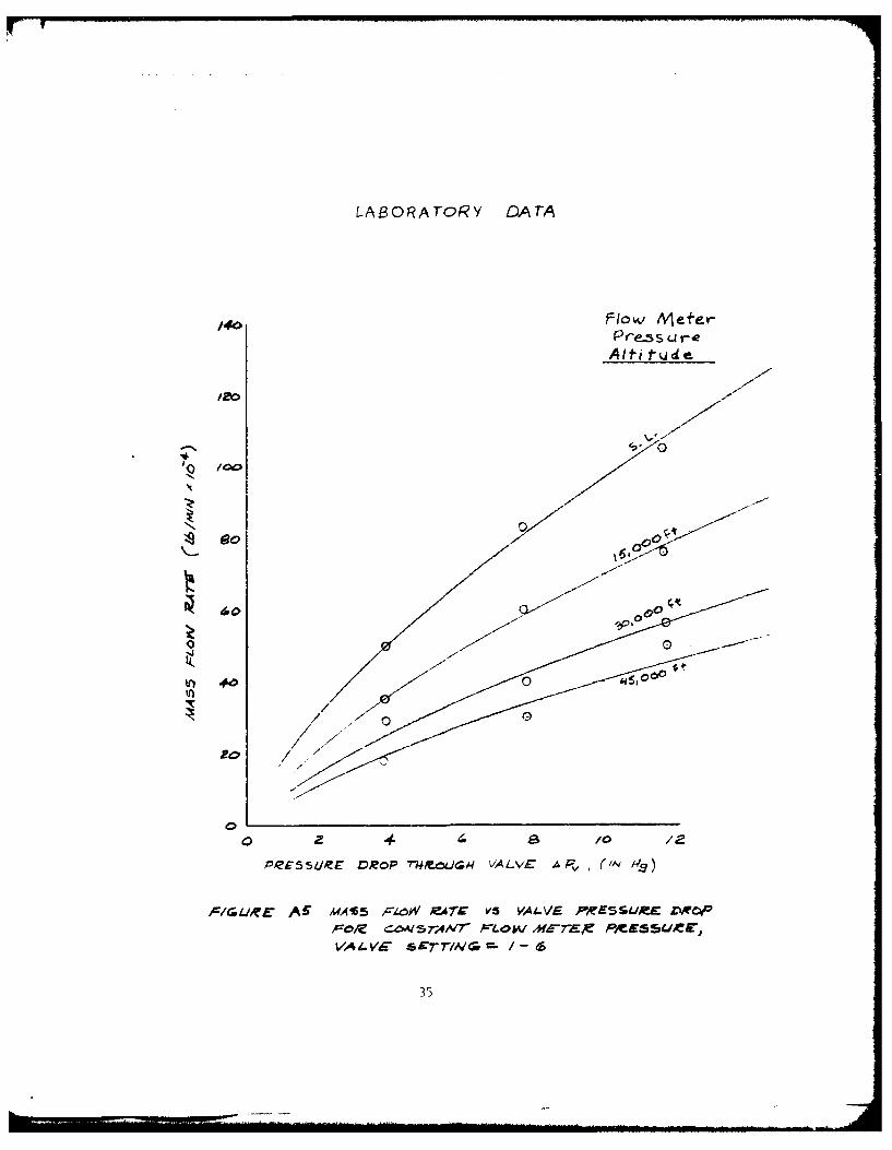
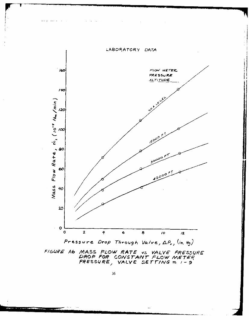
Ground test data was plotted according to the description shown infigure A4. The data measured in the laboratory tests were plotted ascomputed mass flow as a function of pressure drop across the leak valvefor particular values of pressure at the volumetric flow meter and leakvalve setting (figure A5 through figure A7). The resulting fairingswere then cross plotted as pressure drop as a function of pressure atthe flow meter for particular mass flow rates and valve settings ,figureA8 through figure A10).
The leak test data measured during ground tests on the test aircraftpitot system consisted of airspeeds and pressure altitudes pumped intothe pitot-static system, volumetric flow rates, and times for the indicatedairspeed to decrease through specified bands about the test conditions.Initially a mass flow rate was calculated for each test by assuming thatthe pressure at the flow meter was the value determined by the airspeeddialed into the TTU-205 pressure test unit during each leak (50 kt).The TTU-205 was assumed to be an ideal sink (evacuator) . The pressureat the flow meter was not independently measured. The computed rateof airspeed decrease due to each leak was plotted as a function of thecomputed mass flow rate (figure All).
It was assumed that the ground test data and flight test data couldbe correlated by choosing a pressure drop across the leak valve (corre-sponding to a qc or Vc as the leak check standard), by determining amass flow for each valve setting and thus predicting the leak check rateof airspeed decrease. This final parameter value would be plotted againstthe airspeed errors determined from the flight test data for the chosenvalve setting and the other parameters involved.
The aircraft pitot leak tests were conducted under conditions whichwere assumed to create a pressure drop across the leak valve of eightin. Hg. Application of this value to the laboratory data indicatedthat the mass flow should have been higher than the values which werecalculated for the conditions assumed for the aircraft leak tests (figureA8 through figure A10) . Since the results of the two different tests wereexpected to be similar for given conditions of pressure, pressuce drop,and valve setting, the differences between the mass flow predicted 'vthe laboratory data and the calculated results were attributed to thupressures assumed in the aircraft tests. Thus it was suspected that theTTU-205 test unit was unable to evacuate the test apparatus rapidlyenough to maintain the eight in. Hg pressure drop across the leak valve.The calculated pressure at the flow meter was based on test total pressure(from Vc) and assumed valve pressure drop.
The aircraft leak test data (mass flow at assumed pressure) wasplotted on the cross plots of the laboratory mass flow fairinqs (fiqureA8 through figure A10) . The valve pressure drop interpreted for eachdata point was considerably belov the value of eight in. HJg used in thecalculations.
The mass flow computations were corrected by appplyinq a pressure
33
6RCUND TESTSLA80RAI-OR Y AIRCR~AFT.
.a/ve. ~setrinq WO bhol Sires ~ ye 0-"' ys holek sie
and pressurae drap acroms leak -tc /-W pts&h.:- pte-ak Y4Iv. (A6Pv) ,IeA,3L4rc. VONOfuv*. ;lo ow
der-ee5e 1-4IroLmA a mm
ksi . o&tn TIe eZ/mfiPO
-11' vs P 0^~ cvroixplot- 6
c.ross plat /
ct/
V. 5 =54c//
COfRELAT-1 0
ccIGLIp AL'Y- O~rIr/o4 oxS Po.NAL (V/PC Pr
L.EA4 Gi~ovND rEST DATA
34
LABORAropy D)ArA
140F/ow. MVeer
Alt-itude
00 ea
600
40
in) #
P~eESSLIR4 ZROP 7W-04a VALVE A , (1,v h)
F/IGUiE AC ASA5 FA-ZV A7,V V's VALVE PIR'ESSUJRS £WOF"
,-/ CZWI57,4NVr 7.W 7A PUSJVA L.Vig s c7-r/Al - /-
LA80RATCRY DATA
160Al r~O/ MEz~lg:
S4O
+~y
\j5
tL
2.0
00 If to (
Pressure Drop T-bv-OL, Vav e ,P,; (ui.4
F1641,?-- Ab MIASS FLOW RATE vas VALV6E PRS-5URF'PbR6P Fo*? clvsr7,4Nr FL-OW MCTEq-'RESSURE) VALVE ,sE rr/vG ~ -9
36
LASOPAroARY cArA
A Lri rucE
/~00
4
20
PZ,-5UR-'E oe.6p 7WxO/6 MVU ,- (N
,-6z A7 MASS r4-OW.~ RA7C V-S VA4L-Vr F'E53u./V- DP4)
,-OC cON57rAM7- -LOW &fC-EX Pff-EZ 5LW1C
vA d.VA- SET7/ks. 91-o
it.
-~ c0
.44-
43t
0 4-
LL
I-1
38 4
IL
-it=
ctj
--- 4n
0 A
'AdIVCfWC -P~nS-a-A
LLI-.39
Ul w
0 z 0 QLj
4- N
c CL 4r
00 0
to -Z
e 0 440
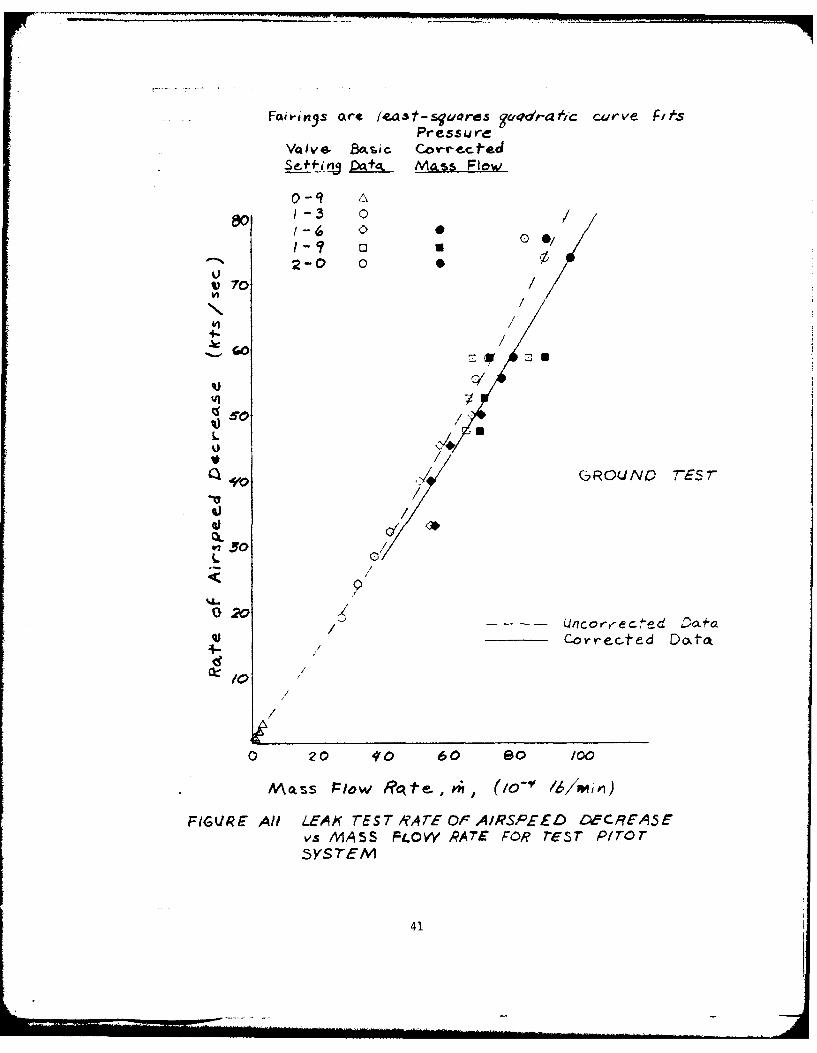
Faitings art /east-s'ares 'id#a7'c curve FiesPre$ss ure
VIve. B.siC CorvrectedSe-f fiv1j pA Mass Flow0-9
1-3 019 -6 Q 0
? 0) 0 /
2-0 0 0
V 70 ~//\/
v4- /
',30/ GROUND 7 7-
j /
4- Cor retcted Dt~a
/0
0 20 4'0 60 so /00
mass Plow Rc'tt" , Pit (1o-0, l /mii)
FIGURE All LEAK TEST / ATE Or AIRSPEED DeCREA5Evs MASS F.OW PRATE FOR reST P/0or3YSTEM
41
correction to each test condition based on the difference between thoassumed and plotted valve pressure drops. The plotted lower pressuredrops for the computed mass flows implied that the pressure at the volumeflow meter was higher than expected. After computing the corrected pres-sure conditions at the volume flow meter, a new set of pressure dependentvolume flow correction factors were determined. New corrected volumeflow rates and densities were computed. From those values a set ofcorrected mass flow rates were computed. The corrected mass flow rateswere plotted on the laboratory cross plots (figure A8 through figureA10) and as the leak test rate of airspeed decrease against mass flowrate (figure All).
Since the leak test data was not measured under consistent pressureconditions, it was necessary to assume that the laboratory data fairingsrepresented the pressure and mass flow relationships for any givencontrollable conditions in a leak test on the aircraft. That is, forgiven conditions of pressure and pressure drop, the mass flow throughthe leak hole could be interpolated from the cross plots of lab data.
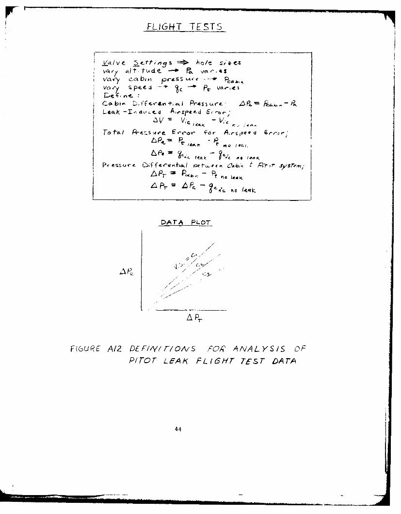
Flight test airspeed data consisted of instrument corrected airspeedsfor no leak and leak conditions and the associated cabin and flightpressure altitudes. The altitude data was converted to cabin differentialpressure, APc = Pcabin - Pa, as for the static system leak tests (figureA12). The airspeeds were converted to impact pressure, qcic, and theairspeed errors were converted to the equivalent total pressure errors,APe = qcic leak - qcic no leak. The total pressure error, APe, was thenplotted against the pressure differential between cabin pressure and theno leak total pressure, APT = Pcabin - Ptic no leak = Pc - qcic no leak(figure A13).
For the purposes of this report the ground test data was correlatedby using a pressure drop of 4.5 in. Hg and pressures of 29.92 in. Hg(sea level standard pressure) and 24.90 in. Hg (5,000 feet standardpressure). The pressure drop of 4.5 in. Hg is the leak check qc condition(total minus static, hence pressure differential) which is obtained bysealing a pressure in the pitot system which causes a calibrated readingof 300 kt on the airspeed indicator with the static system exposed toambient pressure. Since the data was affected by the static pressureat the flow meter, the results were generated by assuming two pressureconditions; sea level and 5,000 feet in the standard atmosphere. The300 kt leak check condition was used because the results fall withinthe range of data measured in the aircraft leak tests.
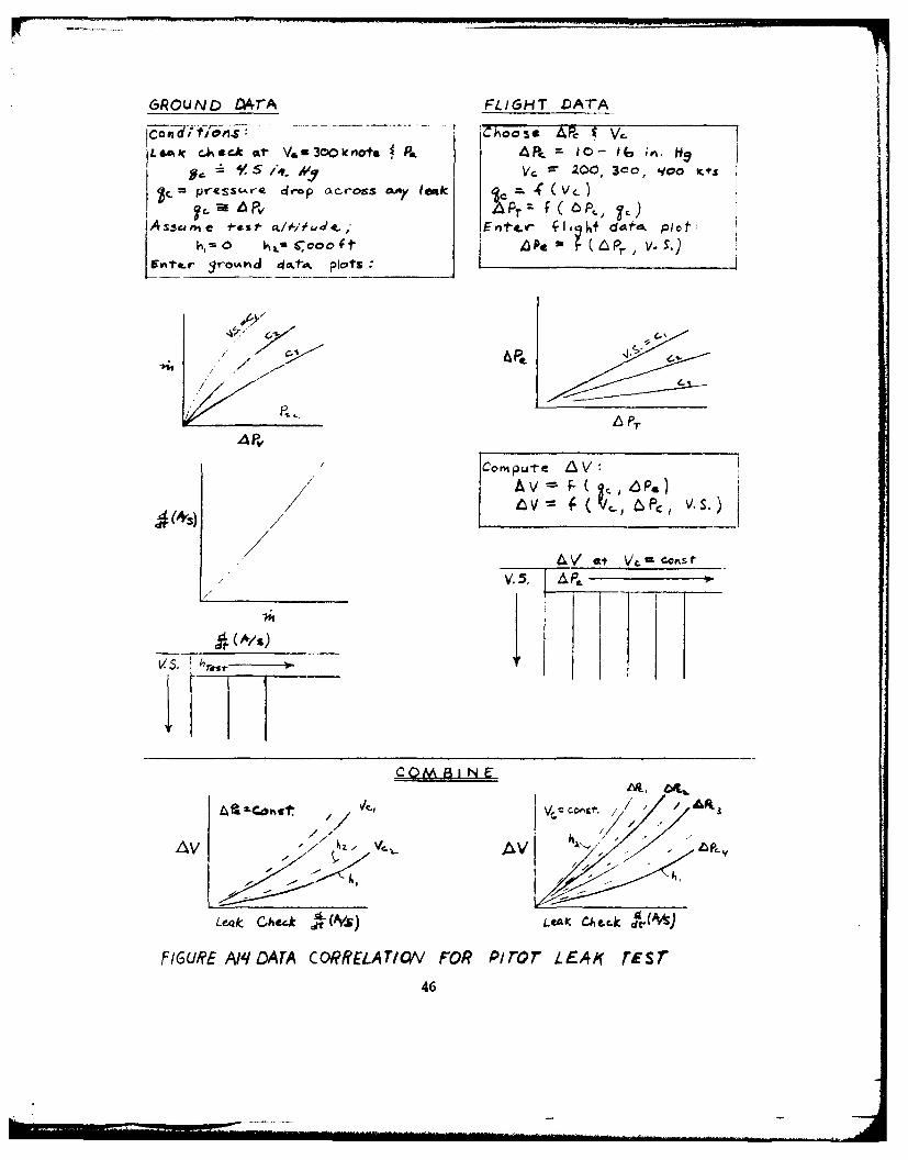
The procedure (see figure A14) used to correlate the ground testdata was to enter the lab data cross plots at the specified pressure dropand static pressure (4.5 in. Hg and 29.92 in. Hg or 24.90 in. Hg) andinterpolate a mass flow rate for each valve setting. Then the expectedrate of airspeed decrease for each mass flow rate was determined fromthe fairing through the aircraft leak test data on figure All.
The predicted airspeed errors for a leak in the pilot's pitot systemin a KC-135A aircraft which are shown in this study were generated byusing the results of the ground and flight tests (figure A14). The primaryparameters affecting the magnitude of the airspeed errors were cabinpressure differential (APc), impact pressure (qc), and the leak hole size.For given conditions of APc and qc, the pressure drop across the leakhole, 'PT, can be computed. For each value of APT thus chosen, thefairings through the W~e vs APT flight test data enable one value of
42
APe to be determined for each valve setting used. The pitot pressureerrors, APe, thus determined were converted to airspeed errors, i,based on the airspeed chosen. Each valve setting was converted to aleak check rate of airspeed decrease based on the ground test calibrations.The computed AV values for each valve setting were plotted against theleak check parameter and a curve was faired through the points.
The ground test data was utilized by determining the effects of a4.5 in. Hg pressure drop across the leak valve. A calibrated airspeedof 300 kt results when the difference between total and static pressureis about 4.5 in. Hg. Thus the pitot leak results of this report can beapplied to KC-135 pilot's pitot systems configured like the test systemif the leak check is performed with the pitot system pressurized so thatthe airspeed indicator reads 300 kt for the static system at ambientpressure. This condition would develop 4.5 in. Hg pressure differentialacross any leak hole.
43
FLIGfT TESTS
i VOL' rl biv e r S - P
COk A L ff'rL0 +, eAI Pre5tAct Ur
V ,. - V,
Tofa/~ Pr!.st4ve E,-v-ov- IFr A4i-joet
4L 9.
DArA PLOT
a Pr
F(GURE A12 CFIIYIFIO' '-ORAAYSSO
P17,or~~~ 7'KFt6rTSTDr
/4
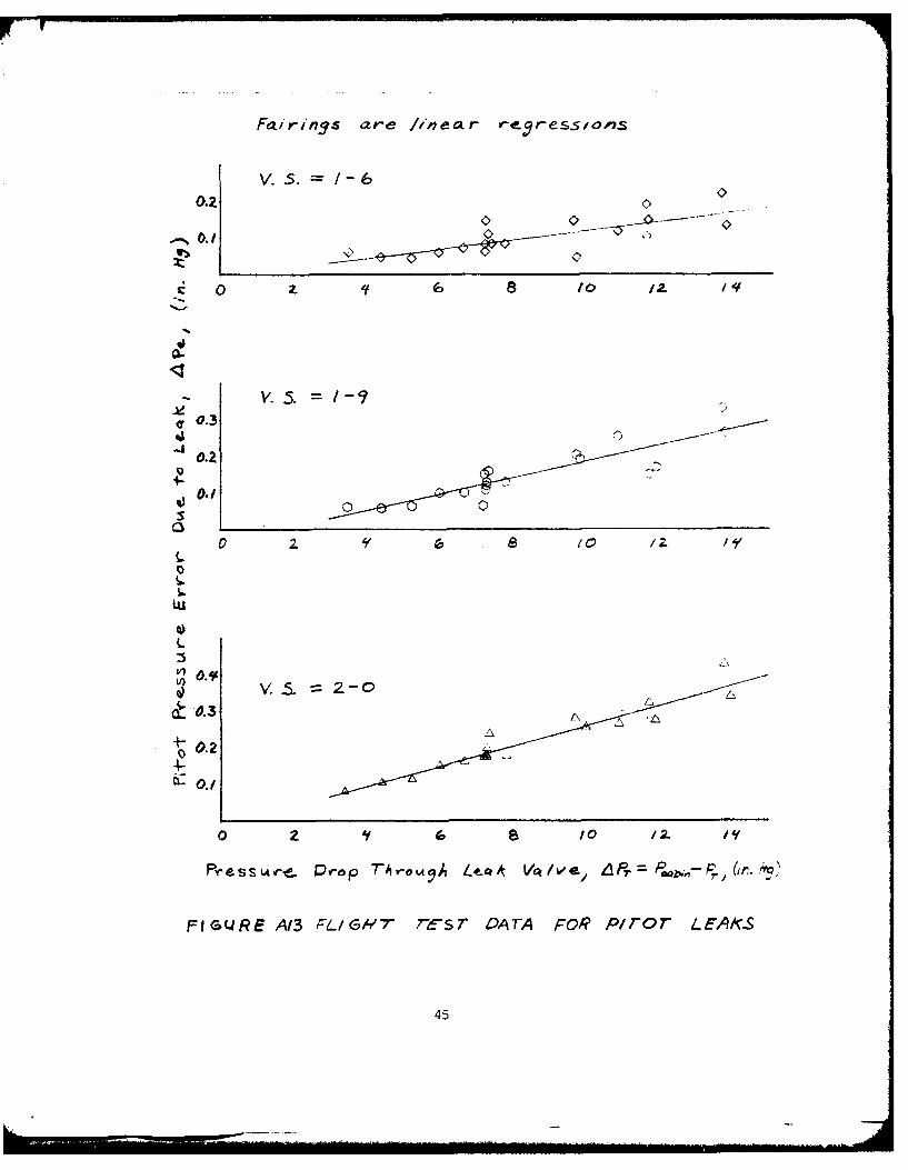
Fti rinys ar-e /inear e P r-ess/,oils
= ~V. 5. /-
~y0.3
-------
2- /-
Os
L
V0.2
~- 0
Pssveue Prop TAvoA LtQ/A V/ve, 68r=Pwpi,-Pr
FIGUJRE A13 FLIG/-/ re-sr DATA FOR4 P/ror LrAlcs
45
GROUND D4rA FLIGHT DATA
con lfm Chos Pc V,~LA c.k t V&a300 Ic not& i AP. 4 DO=1- 16, ;r.H
h,7 V, , ' 200, 300, 'ieO Kts
=C preSSCAV-4 (10Op O2crOSS a.A)y leak (vc~'
SAssume *-es' cti-i, 4 ~t Entt -d *- I" - f dektv Plot:h0 - C~oco ft P4 ( APr ,V.5
E~1-.r 3r-o .tii Plots:
c-i-e
Corm put e 8AV
tV at+ \4uV. 5.
~~4.E V coi,&IF /
/7v &V P,
Le4k Check it(P.6) LCeAK ChAcc-k r(&
FIGURE Am DATA CORRELATIONV FOR Piror L44K TEST
46
APPENDIX B
TEST DATA
47
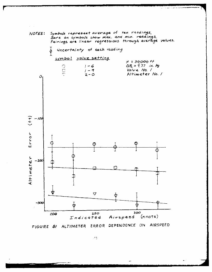
NO0 ES 5yrnbo/.s re-pr-6eseovt avdt-age O'f ten.'
,Sars 6#1 SymbolS Show Met.. ani mto?. r-44dim, S,
(JncertckiP1*y of eac~h ,eidinjq
syriibo valve s*i~
6 P97 7 in. tlLT Valve. tYo./
S2.-0 AIimefer No./
-. 0
200 Z50 300
2%S7-dic qt cd A 1 sp e r-d (K n015)
F)GUIE B1 ALTIMETER ERROR DEPENDENCE ON AIRSPEED
Va/ve~ NoAttinieter No".&...
V. ~-[6: Y0 9.8,n /ea63 v1 O~
o /6.3 ~
sha4ed symibols are3 0 ,0, 0 0 CLd
.7 2,o~oOr
d-
4-
1 0 0 V00
.3 y .
Mar h .3b-
1,GR 9 AHI~~g- F"C NSAI
PRSUE RO
Valve d 'o: /
o. S.8 1- q3 000f
VS. 2--o: 0 9?, 0 1
shaded symbols a reaoooo f d4 a
0-7
0.76!ioco
0~0
1.. 0
LDOL-k f-rois Vot/Ve nRo. / w not M'f~J'~- 2./
o 0,000 f t
oq 000o f t
Vv--,000 11-t
-'L I. 0 - ef il
"7v s ,41n
kuI
q 8102ZfYaIe ein -
0//
FISQF6 PESR RORv AI DFEE7A
FR5UE/3 WELA AV Fr/G
LDcL- o From valve no. a .nd 4l1/.fl4.- no. 2
0 , 0co 00. 0,000 ij
3gooo j t
o~z0 *; oo t
Valve S-ftiny - /-4
- o~ 0
V -
q l 6 8 /0 12 /1
0E
I-
o 0.2
IQ.
-0.2 Vlve = 4P, in H,
FIGURE B-r PRESSURE ERROR vs CABIN DIFFERENT7IALPRE SSUPRE FOR? FHREE LE-AK VALYE SETTIAIGS
52
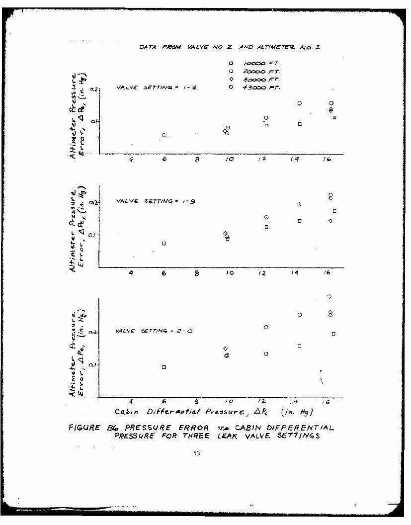
DA 7A PROM VA L VS NVO.2 4ND ALr/*fET7M A/0.1
o /oco
VALVEX -5-- IN( /-6 0 43COi-r
~~0fri .9
a0
cc 0
1 0
00
00
4 6 82 G0/2
CoA',in Diffevrsm~tl Pressai-e, AP, (in. h',3
FIGURE B4 P#?(SSCIRE E$?ROR -tr, CABIN DIFFEREN7T/ALPRESSUcRE FOR THREE LEAK VALVE SETT/,YGS
53
Data OWtaine4 frotq o.1fimater- A0O./
cl Valve nio. /
~~-Valve ')0.2in
-. qto iZ.
~.2
Cabi 04,crefa PrtsueC -l-
FIUR B7/v PRESUR ERO sCBNDFEFv1PRSUEFRrRE ENYLESMG
54a ~ - -
Fa _qz~~ atre //ihea.- r~e ,-sslo~~s 1'truyi daxto
Aly#/mdter- A/b./A/t/meifer No. 2
Valve se-iini -
04f
Vla~ 10tin 12 1-
0.2
4- 0
C~bin Dhrrerenthiql Pressvre, &LPC,(A.~
F16URE 68 COM1PARISON OF LEAK-/NOUCEO E~f4qORSMEASURED AT AND2 6PS7-REAA OF LEAK(
Fairns oute finer regnes~ioris throuqh dct+c.Leak~ ta valve no. 2
Alftmree- Noa./Alfeme'ev- lwo. Z-
Solid sybl are v~a/ie Sefti'ng Ivalveseffings
t1gz A/&'dfvde/2-0
3 o 300# Jcr
47
/0 00 F
77
v49 de~ -I
/ - CC)
/C
01 .04-h
<L
of
FIGRE 47COMPARISON OF LEAK-INDUICED ERRORS MEASQRF.OAT AND DoV/AISTREAM OF LEA)(
56
4ED
4cc
C. ml- 0
400
/ / / 1. .
, / /I
0-
S/ /
//• ,. t' ._
QC
. , ,,,, -. -
. / '0-' /
'
/ 0_
II
5"7
...... ....... "1 ..... ............. 'd......0 ........ .. ..... I. ...... - - il~l. .. ...... iiI.. .... ... . . ,l

00
- --
c/
11 <i /LL 0 f
/cI /r
SRII
r~i~ F F]tt
(44 -I toJ A
- ~ I I/
I /58
Fl 1
(1
10
1~'44
t QQ
-4 OA- -A A-4
59
~A> /
0 0 02
/ - K
/ 0
N /
?0
74-0
Jii
qj~
LLi
i o Lu
-/ -4I
61
I / 1Zi./ -J -S
61J
00
Vu-~ u-I
4d- 1
L-.
AWA
tLL-A C>-4-4 3 J
I,. 62
Ca lib ra I-ed
4-/0'
'-
-
300
4-. - ~ ~ - S O -6-- 0
4-~ -/0 20 30 o
-0 -200
161
APPENDIX C
TEST RESULTS FOR TEST AIRCRAFT
64
No fe; Apply to~ /fC-/.3CA
Or'ticj dc.rtct &in'm ValveS no. 2 and a/*irneter t~o./
rPq~ylq~s bosed o'1 d - de-,ived f ron i-iires E5and 87 pe-,- Appendcix~
-0 /0 20 -. 0 6
Le~l ;;;§;-- ;a' e of- De-s-cerr "/,coo Ft/Irn
FIG41R9A Cl E~FFECT OF LEAK' ON /ALT/METER , =/0Oc oFt
65
Origin~/ dc&- Fromn valves no. I 2 afid a/*/,nefer ,/
Fectr'q baised on da+ -c derived Fmrm Flicurez. 5atnd 67 ptr Xppel~d/x A
_10
--
-5m
0 /0 20 30 If0 , 60
A.eak Check RaOLe of D5escent (1,oo~ftl/in)
F/G(WAqE C 2. EFFECr7 OF LEA)( OM ALT/1ME5 TFR91 , /20 000 ---
66
A'ot-e.: Apply t-o KC-/3.6A,
Orl 91 aI da-t-a From valve~s nib. 1 2- and adh'm~f *-r yio./
Fairiv1qs based an dcai-a~ derieved fyro*m I'ur-es -1a~nd 97 pevr Appendi'c. A,
-0
IL
4-
0 10 2. 30 40 e
Leak& CheckA Rate of Desc.erit &,ooo -t/min)
FtGuRE c 5 EF-ECr oF 4,64A OVY AL7ME7-ER,1 3cooo Ff
67
NYot'e: Apply frco /'C--357A
Orjigino dGL+cx f mm vcaives no. Z a . &#d a~hmeIer- no.I
Fae'rings ba.sed on dat-a derived rvmjv F/ ores -1
and 87 poer Append~ A.
00
-500
-20 'N0 -O s 6
PI LE cy NF~rO EXO L-M~ER ,=Y,0
06
No*&e: Apply to KC-125A
OD-iginal data' romn vaves no. I 2- and cdI-imefte,- no.I
Fairings basei on da -C- derived fromv Fiquv-es 6
a~nd S7 per- Appendl'.x A
0
-100 .14000
-500I
0 0 20 4'0 IV 0 60
Lc-ok Check 'alle of LOescer-t (I.C~' ft/,?
#f~R/eE CS &FFECr OF 46Aof ON ALTIMETER, 4P 6 It. 64?
69
Not,-: Apply to R(C-135A
Ov'tqiojnaj do~tc. froM valves r~o. / 2 a~nd fb,ne-tev- no.1
Frains ba~tsed on dai'o. deriveOc from~ Figures S'an 7 per- 4,aC-,7di4 A.
-/000
300 N 100
to -30090 IT16
L-eaok Check Rolle of Descenvt (1,ooo /mrn )
F/04(RE C& EPFEc~ roF LEA)( ON ALTJMETER, AP,, B in. #9
70)
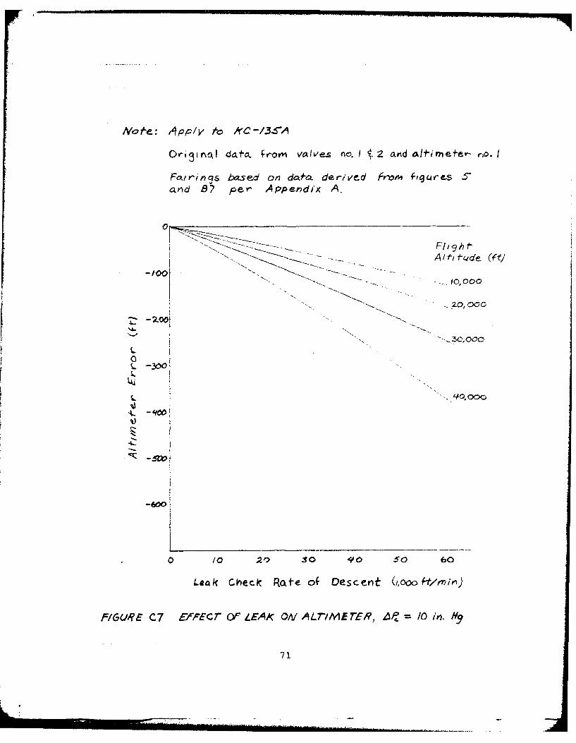
Ma*ft: ,4pp/y ~kC/$
Orl 3ir~oaj da.. frovm' vaIveS no.! 1 2 cavddf1irme er- ro. I
Fettrins ba~sed on~ dco.o derive-d Fron 4ftgjres S'
anid B7 Per APpeni'dx A,
A/f t fde (ct)
3001
I..
-W
0 /0 20 30 io so 60
LeAk Ch~ec~k Rate of Descenit (i,ooo~tlrlion)
F/G44RE C7 £'cEcr OF LEAK OA/ ALT-/ME rEl, 4,, /0 in.N
71
Nof : Apply to KC-LI3TA
Origin*) dala From valves no. I t 2. a et;ew" no. /
ir'itig-s based on data derived won Figures S-and 87 pe' Appetni A.
Ath tude ( t)
-200, W, ...- "-' . 9k O
2J -VO0C04- 0N
0 /0 zo 50 el 0 oro eo
IeaA Chec-k Ra e of Descent N,'ooo f /Iin)
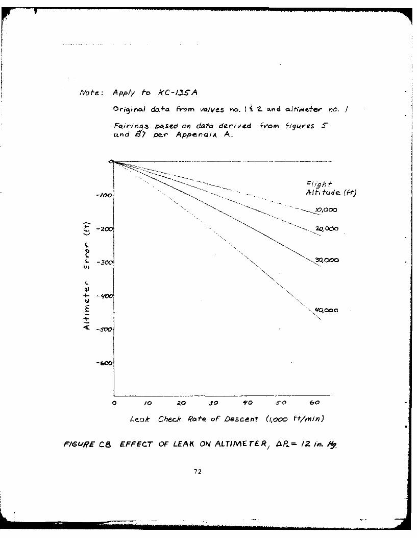
F/SUE C8 EFFECT OF LEAK ON ALTIME rER I L- /Z M. h,
72
Mol'e: Apply t-o /f C-/36A
Origialdo- e from volves n / 2 anda aiobmetler no./
Foirl'ng-s bosed co' daoen derived fromw fig9-wres C
cu'~d 87 perx Append4ix A.
LLA-. -" 6,0
'4-
cv
Yc.3ooo
-600
Lecak Chieck Rate oP Descenit (IjoooFt/hmin
P/&C/I't CT EPFCT OF LE4/f ON ALTIMETER, AP Y9.F
73
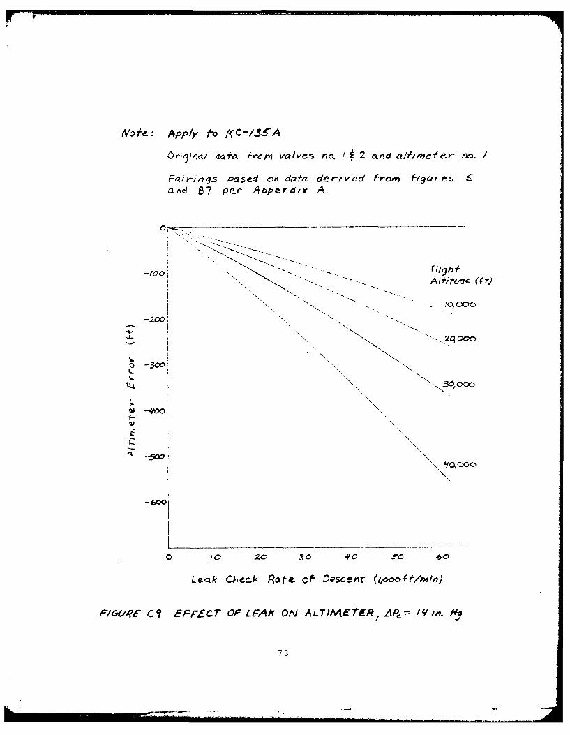
No~:Apply t-o AC&/365A
Or~nod -dafo-, ro* vale~s rio. 1 2. omd adim~~ no. t,
fctriv bcased on dah . dervived Fr'orv f-iur.s 45 an~d
87 oer- APpendi&. A.
f0
-A0 I iA±, e
-200 ic'
S-300
LUj
L
v 0000
-
-5000
* 0 to 20 30 'ic so 60
Leak Checrk Rate OF Descen - (,ooo t/mi,)
FIGURE C/O. EFFECT OF Lff4K. ON ALT/MET,R, 4Pm 14 in.lri.
74
PvrIovM /eat(I Che-K a-t 300) /cnof(-.
Lea Chec~kAirfittd Afttt'..e
_____=Sea LevtI-
('Io
0
0 20 / 5, 00
757
.......Nof'e _: Apply to .XC-,136A . . .... .
trPormv leak ch7eck af 300 knot.
Leak Chkec.kAirfe ed A(1Hhde-
Se Level-.. S' 000 f-t
10 / 20o
Vc.KrQ/
L4
30
//
L/
0 2- / 0
g , /
Lu /
1. /
LeIK Che~ck Airspeed Dec.rease Raft (Kf-t/sec)
I=IGU,?E CI2 PI/"O7 LEM( AIRSPEED ERRORS WITH .AP, -2 in, "/
76
I . . . . . . . . .
Mofe.:Apply t-o (C-/3$-APer~orm feak ch,-CK at 300 bnol-i,.
Leak Check
Se4 Leve.f V,- (knoos)
/ /0
4-o
!LI
4.
-I-- /
/q C
00 o 0 3 Io so 00
Le~l Chck Arsped Dceese Rte ktsler-
F1(Jr C3 ~orLEX4jsPE> R// wrA P,/- H
77-
No le - Appy'o /<-3/Pe.-r-pvm leak, Ch-r-rk -W no-
Leak Chec~kVCcmaA,~-fig/d At'&f
Sea Level15 00020c
00
q0
0 10 0 3050 /
Leak~~~~~~~~ ChekArpedDceaeRte(t/seFGR ittPTTL~ ISEDERR 1-
4 P/ #
787
NVote-: Apply to /<C-/$.SAPer~ormo IeAK a~iecA-k a~t 300ko-
Sea 4 e/
12
//
u/
4-i
oo 30 '0 0
/77.
NoA-: Apply D K C- I-S1"APereorrm leak chec-k at 300 knot s.
Leak. Ch.cicAft-iNed Att/fbde.
Sea Levei
41,
0
L ffn.!
b. /
N- i-
S -/i - -I "7" --
/i 5 ' -- i 1
01 7 7 / 7 .- -
-, 7 -, - - -
No-e-: Apply fo KCto 36APe,"orm lec.. cheec< ct 300 I'nots.
Leak Cher-kAirfield Alfjt.Jde|
Sea L eve/
0
-IIA 1
/0 200 .5"0 6c
Leak Check A'rspeed Decrvase Rate (kfs/sec)
FIGURE C17 AIRSPEED ERROR DU.E O PT'O" LEA/(FORe CRUI4SE A 4/'Oo /Mvors
81
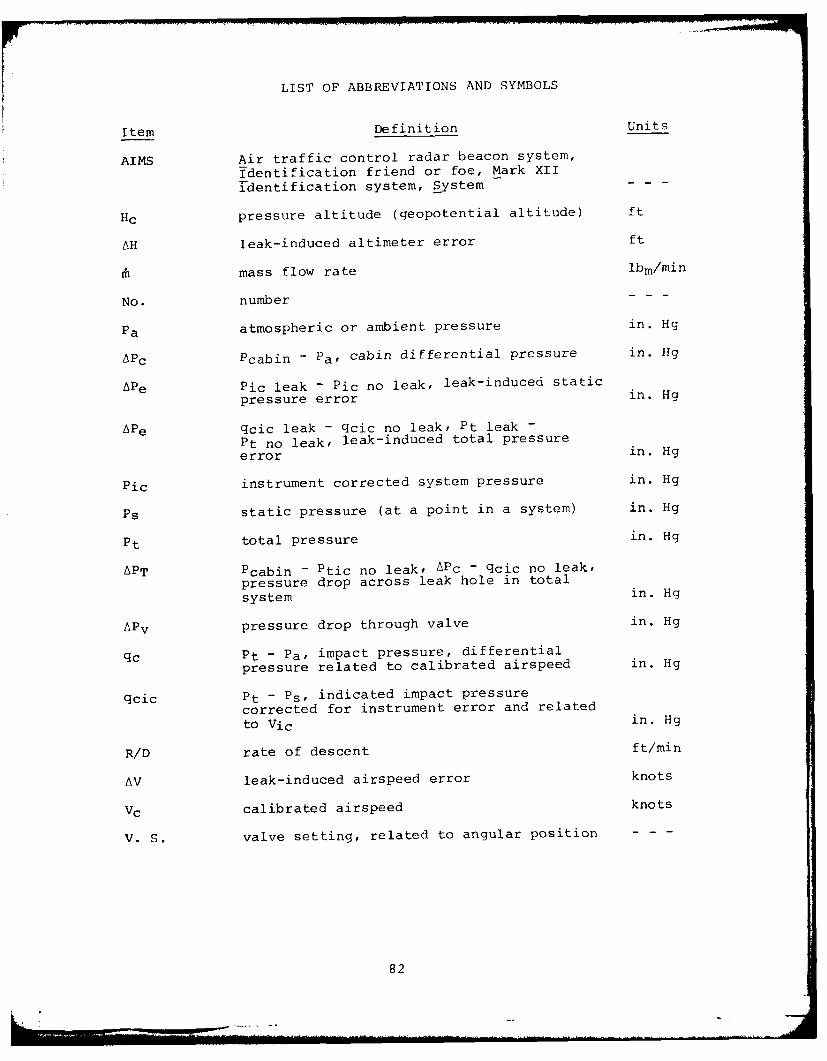
LIST OF ABBREVIATIONS AND SYMBOLS
Item Definition Units
AIMS Air traffic control radar beacon system,
Identification friend or foe, Mark XII
identification system, System - - -
Hc pressure altitude (geopotential altitude) ft
AH leak-induced altimeter error ft
mass flow rate ibm/min
No. number
Pa atmospheric or ambient pressure in. Hg
APc Pcabin - Pa, cabin differential pressure in. Hg
APe Pic leak - Pic no leak, leak-induced static
pressure error in. Hg
APe qcic leak - qcic no leak, Pt leak -
Pt no leak, leak-induced total pressure
error in. Hg
Pic instrument corrected system pressure in. Hg
Ps static pressure (at a point in a system) in. Hg
Pt total pressure in. Hg
APT Pcabin - Ptic no leak, APc - qcic no leak,
pressure drop across leak hole in total
system in. Hg
APv pressure drop through valve in. Hg
qc Pt - Pa, impact pressure, differential
pressure related to calibrated airspeed in. Hg
qcic Pt - Ps, indicated impact pressure
corrected for instrument error and related
to Vic in. Hg
R/D rate of descent ft/min
AV leak-induced airspeed error knots
Vc calibrated airspeed knots
V. S. valve setting, related to angular position - - -
82