Embed Size (px)
Citation preview
ARTICLE IN PRESS
0267-7261/$ - se
doi:10.1016/j.so
�Tel.: +90 45
E-mail addr
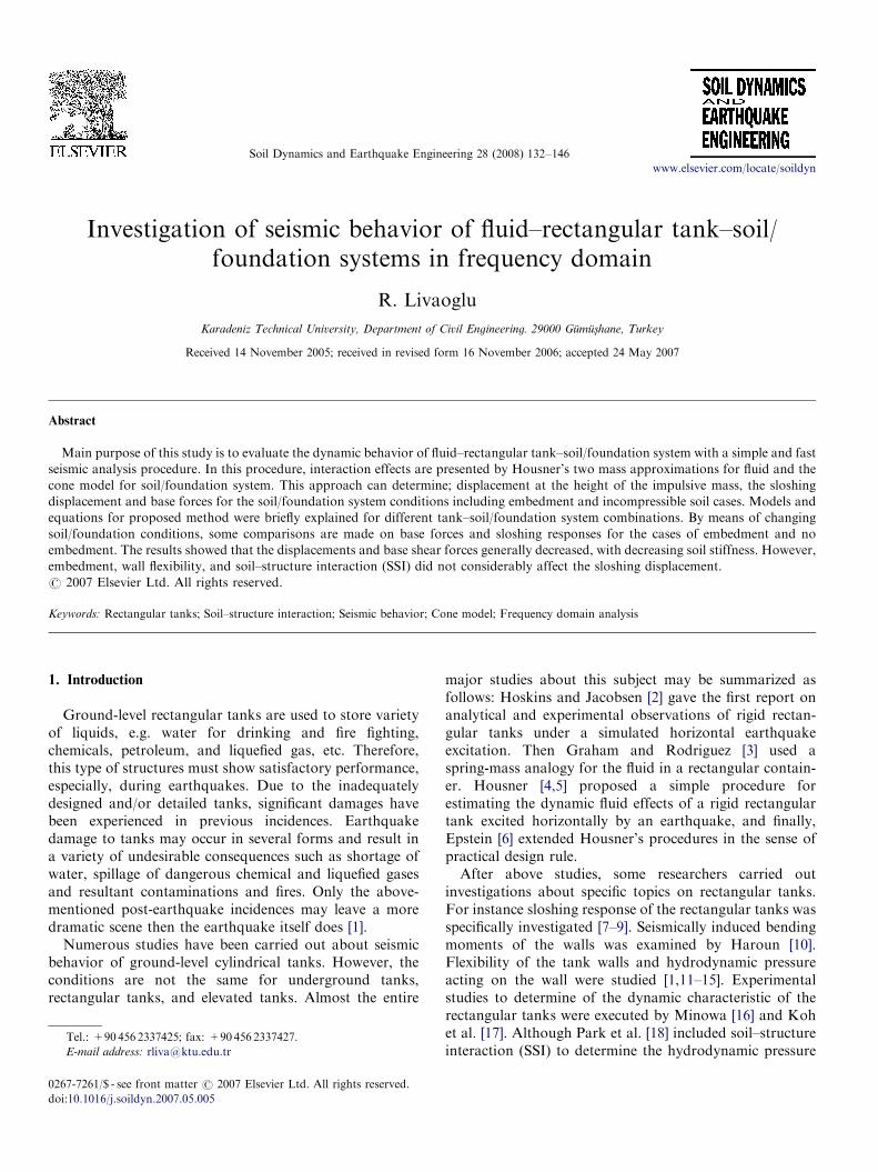
Soil Dynamics and Earthquake Engineering 28 (2008) 132–146
www.elsevier.com/locate/soildyn
Investigation of seismic behavior of fluid–rectangular tank–soil/foundation systems in frequency domain
R. Livaoglu�
Karadeniz Technical University, Department of Civil Engineering. 29000 Gumus-hane, Turkey
Received 14 November 2005; received in revised form 16 November 2006; accepted 24 May 2007
Abstract
Main purpose of this study is to evaluate the dynamic behavior of fluid–rectangular tank–soil/foundation system with a simple and fast
seismic analysis procedure. In this procedure, interaction effects are presented by Housner’s two mass approximations for fluid and the
cone model for soil/foundation system. This approach can determine; displacement at the height of the impulsive mass, the sloshing
displacement and base forces for the soil/foundation system conditions including embedment and incompressible soil cases. Models and
equations for proposed method were briefly explained for different tank–soil/foundation system combinations. By means of changing
soil/foundation conditions, some comparisons are made on base forces and sloshing responses for the cases of embedment and no
embedment. The results showed that the displacements and base shear forces generally decreased, with decreasing soil stiffness. However,
embedment, wall flexibility, and soil–structure interaction (SSI) did not considerably affect the sloshing displacement.
r 2007 Elsevier Ltd. All rights reserved.
Keywords: Rectangular tanks; Soil–structure interaction; Seismic behavior; Cone model; Frequency domain analysis
1. Introduction
Ground-level rectangular tanks are used to store varietyof liquids, e.g. water for drinking and fire fighting,chemicals, petroleum, and liquefied gas, etc. Therefore,this type of structures must show satisfactory performance,especially, during earthquakes. Due to the inadequatelydesigned and/or detailed tanks, significant damages havebeen experienced in previous incidences. Earthquakedamage to tanks may occur in several forms and result ina variety of undesirable consequences such as shortage ofwater, spillage of dangerous chemical and liquefied gasesand resultant contaminations and fires. Only the above-mentioned post-earthquake incidences may leave a moredramatic scene then the earthquake itself does [1].
Numerous studies have been carried out about seismicbehavior of ground-level cylindrical tanks. However, theconditions are not the same for underground tanks,rectangular tanks, and elevated tanks. Almost the entire
e front matter r 2007 Elsevier Ltd. All rights reserved.
ildyn.2007.05.005
6 2337425; fax: +90 456 2337427.
ess: [email protected]
major studies about this subject may be summarized asfollows: Hoskins and Jacobsen [2] gave the first report onanalytical and experimental observations of rigid rectan-gular tanks under a simulated horizontal earthquakeexcitation. Then Graham and Rodriguez [3] used aspring-mass analogy for the fluid in a rectangular contain-er. Housner [4,5] proposed a simple procedure forestimating the dynamic fluid effects of a rigid rectangulartank excited horizontally by an earthquake, and finally,Epstein [6] extended Housner’s procedures in the sense ofpractical design rule.After above studies, some researchers carried out
investigations about specific topics on rectangular tanks.For instance sloshing response of the rectangular tanks wasspecifically investigated [7–9]. Seismically induced bendingmoments of the walls was examined by Haroun [10].Flexibility of the tank walls and hydrodynamic pressureacting on the wall were studied [1,11–15]. Experimentalstudies to determine of the dynamic characteristic of therectangular tanks were executed by Minowa [16] and Kohet al. [17]. Although Park et al. [18] included soil–structureinteraction (SSI) to determine the hydrodynamic pressure
ARTICLE IN PRESSR. Livaoglu / Soil Dynamics and Earthquake Engineering 28 (2008) 132–146 133
acting on wall of rectangular tank in their studies; they didnot propose a practical procedure considering the interac-tion effects. In addition, no studies were introduced onuplift behavior of the rectangular tanks. However, Priestleyet al. [1] suggested a procedure that is based upon theprinciples for cylindrical tanks.
Previous studies concluded that, there is a significantneed for a procedure that can practically cover fluid–rec-tangular tank–soil/foundation interaction altogether. Thispaper aims to investigate how the SSI effect can bepractically taken into account in the seismic analysis of therectangular tanks by considering fluid–structure interactioneffects in a fast and practical manner.
2. Model for fluid–rectangular tank–soil/foundation system
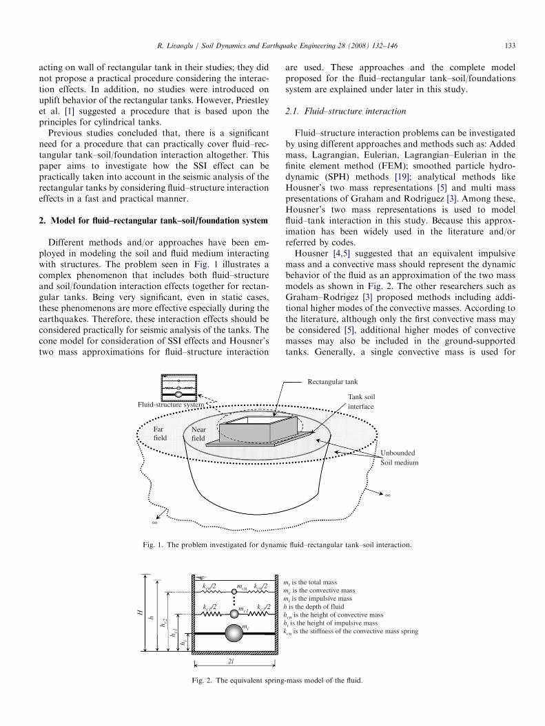
Different methods and/or approaches have been em-ployed in modeling the soil and fluid medium interactingwith structures. The problem seen in Fig. 1 illustrates acomplex phenomenon that includes both fluid–structureand soil/foundation interaction effects together for rectan-gular tanks. Being very significant, even in static cases,these phenomenons are more effective especially during theearthquakes. Therefore, these interaction effects should beconsidered practically for seismic analysis of the tanks. Thecone model for consideration of SSI effects and Housner’stwo mass approximations for fluid–structure interaction
h i
h c1
kc1/2
h c2
mi
mcn
mc1kc1/2
kcn/2 kcn/2
h
H
2l
Fig. 2. The equivalent spring
Nearfield
Farfield
Fluid-structure system
∞
Fig. 1. The problem investigated for dynami
are used. These approaches and the complete modelproposed for the fluid–rectangular tank–soil/foundationssystem are explained under later in this study.
2.1. Fluid–structure interaction
Fluid–structure interaction problems can be investigatedby using different approaches and methods such as: Addedmass, Lagrangian, Eulerian, Lagrangian–Eulerian in thefinite element method (FEM); smoothed particle hydro-dynamic (SPH) methods [19]; analytical methods likeHousner’s two mass representations [5] and multi masspresentations of Graham and Rodriguez [3]. Among these,Housner’s two mass representations is used to modelfluid–tank interaction in this study. Because this approx-imation has been widely used in the literature and/orreferred by codes.Housner [4,5] suggested that an equivalent impulsive
mass and a convective mass should represent the dynamicbehavior of the fluid as an approximation of the two massmodels as shown in Fig. 2. The other researchers such asGraham–Rodrigez [3] proposed methods including addi-tional higher modes of the convective masses. According tothe literature, although only the first convective mass maybe considered [5], additional higher modes of convectivemasses may also be included in the ground-supportedtanks. Generally, a single convective mass is used for
mt is the total massmc is the convective massmi is the impulsive massh is the depth of fluidhcn is the height of convective masshi is the height of impulsive masskcn is the stiffness of the convective mass spring
-mass model of the fluid.
Rectangular tank
Tank soil interface
UnboundedSoil medium
∞
c fluid–rectangular tank–soil interaction.
ARTICLE IN PRESSR. Livaoglu / Soil Dynamics and Earthquake Engineering 28 (2008) 132–146134
practical design of the tanks. That approach presumes thehigher modes of the sloshing have negligible influence onthe forces exerted on the container even if the fundamentalfrequency of the structure is a close proximity one of thenatural frequencies of the sloshing [20]. As in the practicalanalysis presented in this study, only one convective mass isconsidered in the numerical example. Of all expressiongiven in Table 1, proposed ones by Housner and improvedby Epstein [6] are used to be undertaken fluid character-istics.
2.2. SSI
A bounded structure consisting of the actual structureand an adjacent irregular near field soil will interact withthe unbounded (infinite or semi-infinite) far field soil,assuming linear elastic model for the soil extending toinfinity in the dynamic SSI analysis. This interaction can beconsidered in different ways. The first one is a simple
Table 1
Simple procedures for the fluid–rectangular tanks interaction
Housner [4,5], Epstein (1974) Graham-Rodrigez [3]
h/lp1.5 h/l41.5a
mcn/mt 0:527 lhtanh 1:581 h
l
� �0:518l
h16l
p3ð2n�1Þ3htanh ð2n�1Þph
2l
mi/mth
1:732ltanh 1:732 l
h
� �1:064l
h 1�P1n¼1
monmt
hcn/h 1� coshð1:581ðh=lÞÞ�1
1:581hlsinhð1:581ðh=lÞÞ
1� 0:525lh 1� 4l
ð2n�1Þphtanh ð2n�1Þph
4l
hi/h 38 1� 15l
16h 12�
mtmi
P1n¼1
monmt
honh
kcn mongl1:581 tanh 1:581h
l8gmt
hð2n�1Þ2p2tanh2 ð2n�1Þph
2l
aFor the deep tanks (h/l41.5) Housner’s proposed to consider residual
mass ma ¼ ((1�3l/2h)mt) rigidly supported at he height of the ha ( ¼ 1/
2�3l/4h).
ro
ro
uo
Z
vo
vp
vs
zo
u
Axõal
u
zo
Shear
TRANSLATION
Vertical Horizontal
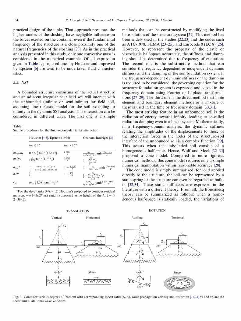
Fig. 3. Cones for various degrees-of-freedom with corresponding aspect ratio
shear and dilatational wave velocities.
methods that can be constructed by modifying the fixedbase solution of the structural system [21]. This method hasbeen widely used in the studies [22,23] and the codes suchas ATC-1978, FEMA [23–25], and Eurocode 8 (EC 8) [26].However, to represent the property of the elastic orviscoelastic half-space accurately, the stiffness and damp-ing should be determined due to frequency of excitation.The second one is the substructure method that canconsider the frequency dependent or independent dynamicstiffness and the damping of the soil/foundation system. Ifthe frequency-dependent dynamic stiffness or the dampingis required to be considered, the governing equation for thestructure foundation system is expressed and solved in thefrequency domain using Fourier or Laplace transforma-tions [27–29]. The third one is the direct method that finiteelement and boundary element methods or a mixture ofthese is used in the time or frequency domain [30,31].The most striking feature in an unbounded soil is the
radiation of energy towards infinity, leading to so-calledradiation damping even in a linear system. Mathematically,in a frequency-domain analysis, the dynamic stiffnessrelating the amplitudes of the displacements to those ofthe interaction forces in the nodes of the structure–soilinterface of the unbounded soil is a complex function [29].This occurs when the unbounded soil consists of ahomogeneous half-space. Hence, Wolf and Meek [32–35]proposed a cone model. Compared to more rigorousnumerical methods, this cone model requires only a simplenumerical manipulation within reasonable accuracy [28].The cone model is simply summarized; for load applied
directly to the structure, the soil can be represented by astatic spring or the structure can even be regarded as built-in [32,34]. These static stiffnesses are expressed in theliterature with a different theory. From all, the Boussinesqtheory can be summarized as follows: when a homo-geneous half-space is statically loaded, the variations of
ro
roo
Z0o
vp
Axõal
�to
��o
�� �t
vs
Shear
TorsionalRocking
ROTATION
(z0/r0), wave-propagation velocity and distortion [32,34] vs and vp are the
ARTICLE IN PRESSR. Livaoglu / Soil Dynamics and Earthquake Engineering 28 (2008) 132–146 135
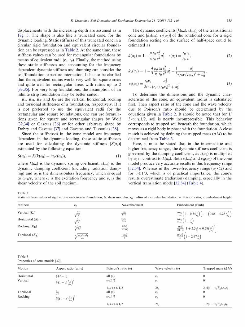
displacements with the increasing depth are assumed as inFig. 3. The shape is also like a truncated cone, for thedynamic loading. Static stiffness of this truncated cone in acircular rigid foundation and equivalent circular founda-tion can be expressed as in Table 2. At the same time, thesestiffness values can be used for rectangular foundations bymeans of equivalent radii (r0, ry). Finally, the method usingthese static stiffnesses and accounting for the frequencydependent dynamic stiffness and damping can consider thesoil/foundation–structure interaction. It has to be clarifiedthat the equivalent radius works very well for square areasand quite well for rectangular areas with ratios up to 2[33,35]. For very long foundations, the assumption of aninfinite strip foundation may be better suited.
Kv, KH, KR and KT are the vertical, horizontal, rockingand torsional stiffnesses of a foundation, respectively. If itis not preferred to use the equivalent radii for therectangular and square foundations, one can use formula-tions given for square and rectangular shapes by Wolf[32,34] or Gazetas [36] or for other arbitrary shape byDobry and Gazetas [37] and Gazetas and Tassoulas [38].
Since the stiffnesses in the cone model are frequencydependent in the dynamic loading, these static stiffnessesare used for calculating the dynamic stiffness [S(a0)]estimated by the following equation:
Sða0Þ ¼ Kðkða0Þ þ ia0cða0ÞÞ, (1)
where k(a0) is the dynamic spring coefficient, c(a0) is thedynamic damping coefficient (including radiation damp-ing) and a0 is the dimensionless frequency, which is equalto or0/vs where o is the excitation frequency and vs is theshear velocity of the soil medium.
Table 2
Static stiffness values of rigid equivalent-circular foundation, G: shear modulus
Stiffness r0 No-e
Vertical (Kv)ffiffiffiffiabp
q4Gr01�u
Horizontal (KH)ffiffiffiffiabp
q8Gr02�u
Rocking (KR)ffiffiffiffiffiffia3b3p
4q
8Gr30
3ð1�u
Torsional (KT)ffiffiffiffiffiffiffiffiffiffiffiffiffiffiffiffiabða2þb2Þ
6p4q
16Gr30
3
Table 3
Properties of cone models [32]
Motion Aspect ratio (z0/r0) Poisson’s ratio
Horizontal p8ð2� uÞ all (u)
Vertical p4ð1� uÞ v
vs
� �2 up1/3
1/3oup1/2
Torsional 9p32
all (u)Rocking 9p
32ð1� uÞ v
vs
� �2 up1/3
1/3oup1/2
The dynamic coefficients [k(a0), c(a0)] of the translationalcone and [ky(a0), cy(a0)] of the rotational cone for a rigidfoundation resting on the surface of half-space could beestimated as
kða0Þ ¼ 1�mp
z0
r0
v2sv2
a20 cða0Þ ¼
z0
r0
vs
v, (2)
kyða0Þ ¼ 1�4
3
myp
z0
r0
v2sv2
a20 �
1
3
a20
ðr0v=z0vsÞ2þ a2
0
.
cyða0Þ ¼z0vs
3r0v
a20
ðr0v=z0vsÞ2þ a2
0
ð3Þ
To determine the dimensions and the dynamic char-acteristic of the cone, an equivalent radius is calculatedfirst. Then aspect ratio of the cone and the wave velocitydue to Poisson’s ratio should be determined by theequations given in Table 2. It should be noted that for 1/3oup1/2, soil is nearly incompressible. This behaviorcorresponds to trapped soil beneath the foundation, whichmoves as a rigid body in phase with the foundation. A closematch is achieved by defining the trapped mass (DM) to bedetermined from Table 3.Here, it must be stated that in the intermediate and
higher frequency ranges, the dynamic stiffness coefficient isgoverned by the damping coefficient, as c(a0) is multipliedby a0 in contrast to k(a0). Both cv(a0) and cH(a0) of the conemodel produce very accurate results in this frequency range[32,34]. Whereas in the lower-frequency range (a0o2) andfor up1/3, which is of practical importance, the cone’sresults overestimate (radiation) damping, especially in thevertical translation mode [32,34] (Table 4).
, r0: radius of a circular foundation, u: Poisson ratio, e: embedment height
mbedment Embedment (Emb)
4Gr01�u 1þ 0:54 e
r0
� �1þ 0:85� 0:28 e
r0
� �� �8Gr02�u 1þ e
r0
� �
Þ
8Gr30
3ð1�uÞ 1þ 2:3 er0þ 0:58 e
r0
� �3� �
16Gr30
31þ 2:67 e
r0
� �
(u) Wave velocity (v) Trapped mass (DM)
vs 0
vp 0
2vs 2; 4ðu� 1=3ÞrA0r0vs 0
vp 0
2vs 1; 2ðu� 1=3ÞrI0r0
ARTICLE IN PRESSR. Livaoglu / Soil Dynamics and Earthquake Engineering 28 (2008) 132–146136
2.3. Proposed model and analysis procedure to
fluid–rectangular tank–soil/foundation system
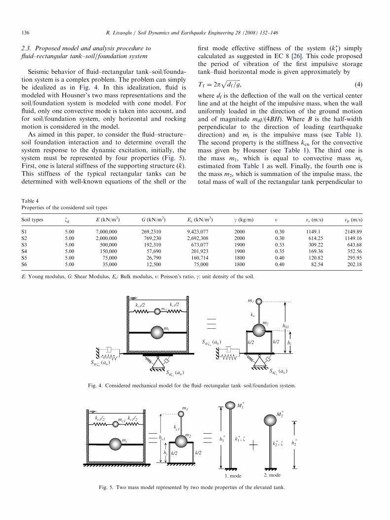
Seismic behavior of fluid–rectangular tank–soil/founda-tion system is a complex problem. The problem can simplybe idealized as in Fig. 4. In this idealization, fluid ismodeled with Housner’s two mass representations and thesoil/foundation system is modeled with cone model. Forfluid, only one convective mode is taken into account, andfor soil/foundation system, only horizontal and rockingmotion is considered in the model.
As aimed in this paper, to consider the fluid–structure–soil foundation interaction and to determine overall thesystem response to the dynamic excitation, initially, thesystem must be represented by four properties (Fig. 5).First, one is lateral stiffness of the supporting structure (k).This stiffness of the typical rectangular tanks can bedetermined with well-known equations of the shell or the
Table 4
Properties of the considered soil types
Soil types zg E (kN/m2) G (kN/m2) Ec (k
S1 5.00 7,000,000 269,2310 9,42
S2 5.00 2,000,000 769,230 2,69
S3 5.00 500,000 192,310 67
S4 5.00 150,000 57,690 20
S5 5.00 75,000 26,790 16
S6 5.00 35,000 12,500 7
E: Young modulus, G: Shear Modulus, Ec: Bulk modulus, u: Poisson’s ratio,
Fig. 4. Considered mechanical model for the flu
kc1/2 kc1/2
mi
mc1
kk/2
kc1
m1
m2hc1
hi
Fig. 5. Two mass model represented by two
first mode effective stiffness of the system (k�1) simplycalculated as suggested in EC 8 [26]. This code proposedthe period of vibration of the first impulsive storagetank–fluid horizontal mode is given approximately by
T f ¼ 2pffiffiffiffiffiffiffiffiffiffidf=g
p, (4)
where df is the deflection of the wall on the vertical centerline and at the height of the impulsive mass, when the walluniformly loaded in the direction of the ground motionand of magnitude mig/(4BH). Where B is the half-widthperpendicular to the direction of loading (earthquakedirection) and mi is the impulsive mass (see Table 1).The second property is the stiffness kcn for the convectivemass given by Housner (see Table 1). The third one isthe mass m1, which is equal to convective mass mc
estimated from Table 1 as well. Finally, the fourth one isthe mass m2, which is summation of the impulse mass, thetotal mass of wall of the rectangular tank perpendicular to
N/m3) g (kg/m) u vs (m/s) vp (m/s)
3,077 2000 0.30 1149.1 2149.89
2,308 2000 0.30 614.25 1149.16
3,077 1900 0.35 309.22 643.68
1,923 1900 0.35 169.36 352.56
0,714 1800 0.40 120.82 295.95
5,000 1800 0.40 82.54 202.18
g: unit density of the soil.
id–rectangular tank–soil/foundation system.
M1
k1 , �
1. mode 2. mode
/2
*
M2*
h2*h1
* *
k2 , �*
mode properties of the elevated tank.
ARTICLE IN PRESSR. Livaoglu / Soil Dynamics and Earthquake Engineering 28 (2008) 132–146 137
the excitation. Modal properties such as effective modalmass, heights, and stiffness can be calculated from this twodegree-of-freedom system (Fig. 5).
Where M�1 & M�
2; h�1 & h�2; k�1 & k�2 are the efffecivemasses, effective heights and effective stiffnesses of the firstand the second modes, respectively. These modal proper-ties can be estimated using Eqs. (5) and (6) [39].
M�n ¼ GnLh
n ¼ðLh
nÞ2
Mn
; h�n ¼Ly
n
Lhn
; k�n ¼ o2nM�
n, (5)
where
Mn ¼ ftnMfn ¼
XN
i¼1
mif2jn : Gn ¼
Lhn
Mn
:
Lhn ¼
XN
i¼1
mifjn : Lyn ¼
XN
i¼1
himifjn. ð6Þ
where N is the total mode number, which is considered, fn
is the mode vector of the nth mode and o2n is the eigenvalue
of the nth mode. Thus, the model can be represented withtwo single-degree-of-freedom systems. Because of theabsolute differences between the sloshing stiffness kcn andthe stiffness of the supporting system k, it should beassumed that the first mode represents the sloshing and thesecond one the impulsive mode, respecively.
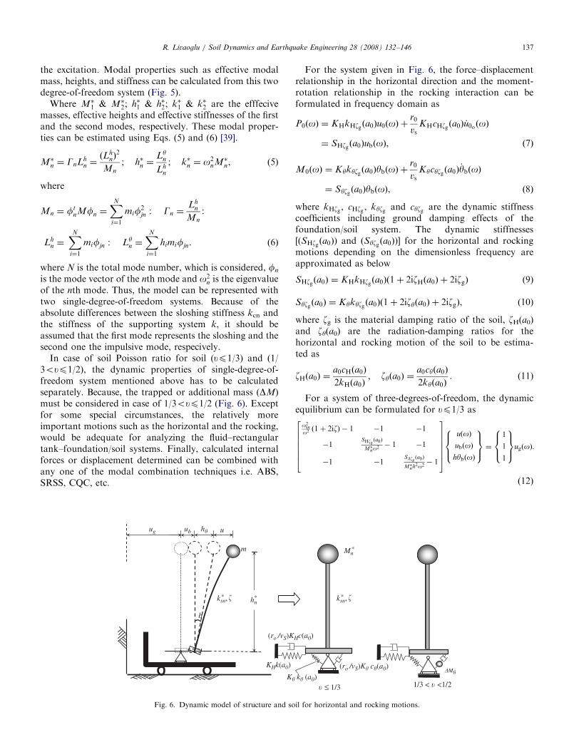
In case of soil Poisson ratio for soil (up1/3) and (1/3oup1/2), the dynamic properties of single-degree-of-freedom system mentioned above has to be calculatedseparately. Because, the trapped or additional mass (DM)must be considered in case of 1/3oup1/2 (Fig. 6). Exceptfor some special circumstances, the relatively moreimportant motions such as the horizontal and the rocking,would be adequate for analyzing the fluid–rectangulartank–foundation/soil systems. Finally, calculated internalforces or displacement determined can be combined withany one of the modal combination techniques i.e. ABS,SRSS, CQC, etc.
K�
KHk(a0)
(ro /vS)K
ug ub u
m
b
h�
*ksn, *hn�
Fig. 6. Dynamic model of structure and so
For the system given in Fig. 6, the force–displacementrelationship in the horizontal direction and the moment-rotation relationship in the rocking interaction can beformulated in frequency domain as
P0ðoÞ ¼ KHkHzg ða0Þu0ðoÞ þr0
vsKHcHzg ða0Þ _u0o ðoÞ
¼ SHzgða0ÞubðoÞ, ð7Þ
M0ðoÞ ¼ Kykyzgða0ÞybðoÞ þr0
vsKycyzgða0Þ
_ybðoÞ
¼ Syzg ða0ÞybðoÞ, ð8Þ
where kHzg , cHzg , kyzg and cyzg are the dynamic stiffnesscoefficients including ground damping effects of thefoundation/soil system. The dynamic stiffnesses[(SHzg ða0Þ) and (Syzgða0Þ)] for the horizontal and rockingmotions depending on the dimensionless frequency areapproximated as below
SHzgða0Þ ¼ KHkHzgða0Þð1þ 2izHða0Þ þ 2izgÞ (9)
Syzgða0Þ ¼ Kykyzg ða0Þð1þ 2izyða0Þ þ 2izgÞ, (10)
where zg is the material damping ratio of the soil, zH(a0)and zy(a0) are the radiation-damping ratios for thehorizontal and rocking motion of the soil to be estima-ted as
zHða0Þ ¼a0cHða0Þ
2kHða0Þ; zyða0Þ ¼
a0cyða0Þ
2kyða0Þ. (11)
For a system of three-degrees-of-freedom, the dynamicequilibrium can be formulated for up1/3 as
o2sn
o2 ð1þ 2izÞ � 1 �1 �1
�1SHzg ða0Þ
M�no2 � 1 �1
�1 �1SWzg ða0Þ
M�nh2o2 � 1
2666664
3777775
uðoÞ
ubðoÞ
hybðoÞ
8><>:
9>=>; ¼
1
1
1
8><>:
9>=>;ugðoÞ.
(12)
k� (a0)
Hc(a0)
(ro /vS)K� c�(a0)
*Mn
1/3 < � <1/2 � ≤ 1/3
*ksn, �
�M�
il for horizontal and rocking motions.
ARTICLE IN PRESSR. Livaoglu / Soil Dynamics and Earthquake Engineering 28 (2008) 132–146138
If ubðoÞ and hybðoÞ are expressed using uðoÞ, Eq. 12 yieldthe following equation
uðoÞ¼1
1o2 �
M�nSHzg ða0Þ
�o2M�nh�2nSyzg ða0Þ
� 1o2
snð1þ2izÞ
� �ð1þ 2izÞo2
sn
ugðoÞ.
(13)
If the same equations were written for 1=3oup1=2Eq. (12) could be written as
o2sn
o2 ð1þ 2izÞ � 1 �1 �1
�1SHzg ða0Þ
M�no2 � 1 �1
�1 �1SWzg ða0Þ
M�nh2o2 �DMyM�nh2� 1
26666664
37777775
uðoÞ
ubðoÞ
hybðoÞ
8>><>>:
9>>=>>;
¼
1
1
1
8>><>>:
9>>=>>;
ugðoÞ, ð14Þ
where ubðoÞ and hybðoÞ are expressed using uðoÞ asThe lateral displacement depending on the structural
rigidity was derived using Eq. (14) in the incompressiblesoil as below:
uðoÞ ¼ugðoÞ
o2snð1þ 2izÞ 1
o2 �1
o2snð1þ2izÞ
�M�n
SHzg ða0Þ� 1
ðSWzg ða0Þ=M�nh2Þ�ðDMy=M�nh2Þo2
� � , (15)
where o2sn (¼ k�sn=M�
n) is the square of the angularfrequency of the fixed base single-degree-of-freedomsystem, ug(o) is the effective input motion in the frequencydomain. It may be obtained by means one of thetransformation techniques like Fourier and/or Laplacei.e. using Fourier transformation, the displacements in thetime domain ug(t) can be transformed in the frequencydomain. In addition, the solution in the frequency domain
tw
2B = 50 m
x
y
y
z
2L =
20
m
2b = 52 m
2a =
26
m
Fig. 7. Plan and elevation of th
can be transformed in the time domain using inverseFourier transformation.
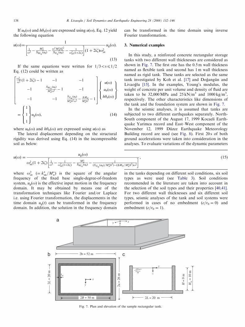
3. Numerical examples
In this study, a reinforced concrete rectangular storagetanks with two different wall thicknesses are considered asshown in Fig. 7. The first one has the 0.5m wall thicknessnamed as flexible tank and second has 1m wall thicknessnamed as rigid tank. These tanks are selected as the sametank investigated by Koh et al. [17] and Dogangun andLivaoglu [15]. In the examples, Young’s modulus, theweight of concrete per unit volume and density of fluid aretaken to be 32,000MPa and 25 kN/m3 and 1000 kg/m3,respectively. The other characteristics like dimensions ofthe tank and the foundation system are shown in Fig. 7.In the seismic analyses, it is assumed that tanks are
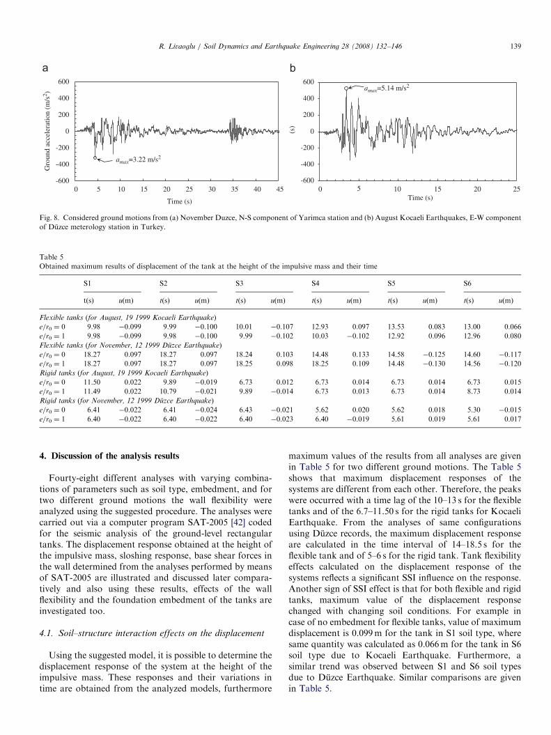
subjected to two different earthquakes separately. North-South component of the August 17, 1999 Kocaeli Earth-quake Yarimca record and East–West component of theNovember 12, 1999 Duzce Earthquake MeteorologyBuilding record are used (see Fig. 8). First 20 s of bothground accelerations were taken into consideration in theanalyses. To evaluate variations of the dynamic parameters
in the tanks depending on different soil conditions, six soiltypes as were used (see Table 3). Soil conditionsrecommended in the literature are taken into account inthe selection of the soil types and their properties [40,41].For two different wall thicknesses and six different soiltypes, seismic analyses of the tank and soil systems wereperformed in cases of no embedment (e/r0 ¼ 0) andembedment (e/r0 ¼ 1).
x
y
z
2L = 20 m
H =
9 m
Hw
= 1
0 m
e sample rectangular tank.
ARTICLE IN PRESS
-600
-400
-200
0
200
400
600
0 10 15 20 25 30 35 40 45
(s)
Gro
und
acce
lera
tion
(m/s
2 )
Time (s)
-600
-400
-200
0
200
400
600
0 10 15 20 25Time (s)
amax=5.14 m/s2
amax=3.22 m/s2
5 5
Fig. 8. Considered ground motions from (a) November Duzce, N-S component of Yarimca station and (b) August Kocaeli Earthquakes, E-W component
of Duzce meterology station in Turkey.
Table 5
Obtained maximum results of displacement of the tank at the height of the impulsive mass and their time
S1 S2 S3 S4 S5 S6
t(s) u(m) t(s) u(m) t(s) u(m) t(s) u(m) t(s) u(m) t(s) u(m)
Flexible tanks (for August, 19 1999 Kocaeli Earthquake)
e/r0 ¼ 0 9.98 �0.099 9.99 �0.100 10.01 �0.107 12.93 0.097 13.53 0.083 13.00 0.066
e/r0 ¼ 1 9.98 �0.099 9.98 �0.100 9.99 �0.102 10.03 �0.102 12.92 0.096 12.96 0.080
Flexible tanks (for November, 12 1999 Duzce Earthquake)
e/r0 ¼ 0 18.27 0.097 18.27 0.097 18.24 0.103 14.48 0.133 14.58 �0.125 14.60 �0.117
e/r0 ¼ 1 18.27 0.097 18.27 0.097 18.25 0.098 18.25 0.109 14.48 �0.130 14.56 �0.120
Rigid tanks (for August, 19 1999 Kocaeli Earthquake)
e/r0 ¼ 0 11.50 0.022 9.89 �0.019 6.73 0.012 6.73 0.014 6.73 0.014 6.73 0.015
e/r0 ¼ 1 11.49 0.022 10.79 �0.021 9.89 �0.014 6.73 0.013 6.73 0.014 8.73 0.014
Rigid tanks (for November, 12 1999 Duzce Earthquake)
e/r0 ¼ 0 6.41 �0.022 6.41 �0.024 6.43 �0.021 5.62 0.020 5.62 0.018 5.30 �0.015
e/r0 ¼ 1 6.40 �0.022 6.40 �0.022 6.40 �0.023 6.40 �0.019 5.61 0.019 5.61 0.017
R. Livaoglu / Soil Dynamics and Earthquake Engineering 28 (2008) 132–146 139
4. Discussion of the analysis results
Fourty-eight different analyses with varying combina-tions of parameters such as soil type, embedment, and fortwo different ground motions the wall flexibility wereanalyzed using the suggested procedure. The analyses werecarried out via a computer program SAT-2005 [42] codedfor the seismic analysis of the ground-level rectangulartanks. The displacement response obtained at the height ofthe impulsive mass, sloshing response, base shear forces inthe wall determined from the analyses performed by meansof SAT-2005 are illustrated and discussed later compara-tively and also using these results, effects of the wallflexibility and the foundation embedment of the tanks areinvestigated too.
4.1. Soil–structure interaction effects on the displacement
Using the suggested model, it is possible to determine thedisplacement response of the system at the height of theimpulsive mass. These responses and their variations intime are obtained from the analyzed models, furthermore
maximum values of the results from all analyses are givenin Table 5 for two different ground motions. The Table 5shows that maximum displacement responses of thesystems are different from each other. Therefore, the peakswere occurred with a time lag of the 10–13 s for the flexibletanks and of the 6.7–11.50 s for the rigid tanks for KocaeliEarthquake. From the analyses of same configurationsusing Duzce records, the maximum displacement responseare calculated in the time interval of 14–18.5 s for theflexible tank and of 5–6 s for the rigid tank. Tank flexibilityeffects calculated on the displacement response of thesystems reflects a significant SSI influence on the response.Another sign of SSI effect is that for both flexible and rigidtanks, maximum value of the displacement responsechanged with changing soil conditions. For example incase of no embedment for flexible tanks, value of maximumdisplacement is 0.099m for the tank in S1 soil type, wheresame quantity was calculated as 0.066m for the tank in S6soil type due to Kocaeli Earthquake. Furthermore, asimilar trend was observed between S1 and S6 soil typesdue to Duzce Earthquake. Similar comparisons are givenin Table 5.
ARTICLE IN PRESSR. Livaoglu / Soil Dynamics and Earthquake Engineering 28 (2008) 132–146140
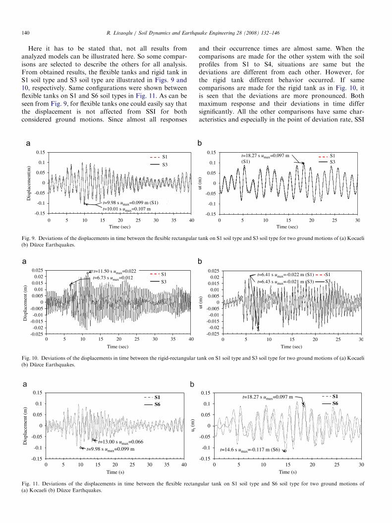
Here it has to be stated that, not all results fromanalyzed models can be illustrated here. So some compar-isons are selected to describe the others for all analysis.From obtained results, the flexible tanks and rigid tank inS1 soil type and S3 soil type are illustrated in Figs. 9 and10, respectively. Same configurations were shown betweenflexible tanks on S1 and S6 soil types in Fig. 11. As can beseen from Fig. 9, for flexible tanks one could easily say thatthe displacement is not affected from SSI for bothconsidered ground motions. Since almost all responses
-0.15
-0.1
-0.05
0
0.05
0.1
0.15
0 10 15 20 25 30 35 40Time (sec)
Dis
plac
emen
t(m
)
t max
5
S1
S3
t=9.98 s umax=0.099 m (S1)t=10.01 s umax=0.107 m
Fig. 9. Deviations of the displacements in time between the flexible rectangular
(b) Duzce Earthquakes.
-0.025-0.02
-0.015-0.01
-0.0050
0.0050.01
0.0150.02
0.025
0 10 15 20 25 30 35 40
Time (sec)
Dis
plac
emen
t (m
)
5
t=11.50 s umax=0.022t=6.73 s umax=0.012
S1
S3
Fig. 10. Deviations of the displacements in time between the rigid-rectangular t
(b) Duzce Earthquakes.
u t (
m)
-0.15
-0.1
-0.05
0
0.05
0.1
0.15
0 10 15 20 25 30 35 40
Time (s)
Dis
plac
emen
t (m
)
t=9.98 s umax=0.099 m t=13.00 s umax=0.066
S1S6
5
Fig. 11. Deviations of the displacements in time between the flexible rectan
(a) Kocaeli (b) Duzce Earthquakes.
and their occurrence times are almost same. When thecomparisons are made for the other system with the soilprofiles from S1 to S4, situations are same but thedeviations are different from each other. However, forthe rigid tank different behavior occurred. If samecomparisons are made for the rigid tank as in Fig. 10, itis seen that the deviations are more pronounced. Bothmaximum response and their deviations in time differsignificantly. All the other comparisons have same char-acteristics and especially in the point of deviation rate, SSI
-0.15
-0.1
-0.05
0
0.05
0.1
0.15
0 10 15 20 25 30Time (sec)
ut (
m)
(S1) S1S3
5
t=18.27 s umax=0.097 m
tank on S1 soil type and S3 soil type for two ground motions of (a) Kocaeli
-0.025-0.02
-0.015-0.01
-0.0050
0.0050.01
0.0150.02
0.025
0 10 15 20 25 30
Time (sec)
ut (
m)
5
t=6.41 s umax=-0.022 m (S1)
t=6.43 s umax=-0.021 m (S3)
S1S3
ank on S1 soil type and S3 soil type for two ground motions of (a) Kocaeli
-0.15
-0.1
-0.05
0
0.05
0.1
0.15
0 10 15 20 25 30
Time (s)
t=18.27 s umax=0.097 m
t=14.6 s umax=-0.117 m (S6)
S1S6
5
gular tank on S1 soil type and S6 soil type for two ground motions of
ARTICLE IN PRESSR. Livaoglu / Soil Dynamics and Earthquake Engineering 28 (2008) 132–146 141
is more effective on rigid-rectangular tanks for all soil typeinvestigated in this paper, but the magnitudes of displace-ments are so small that these changes can be ignored forthese rigid wall systems from a practical design point ofview.
Instead, displacement response of the flexible tanks isonly affected in case of comparisons observed between S1and S5 or S6 soil types, i.e. time deviations of thedisplacements in between S1 and S6 soil types areillustrated in Fig. 11. One can be seen in Fig. 11 that theSSI affected the system behavior so that, displacementresponse decreased almost 33%. Time deviations ofdisplacements for the rigid tanks are different and are notremarkably changed, but displacement amplitudes aredecreased due to SSI. Furthermore, the decreases as muchas 0.033m for ground motion of Kocaeli 1999 Earthqukaerecorded in Yarımca station can cause the tank failureduring an earthquake. Differently for the Meteorolgybuilding record of the Duzce Earthquake, time historyresponse of the displacement show that soft soil conditionincreased the displacement response approximately asmuch as 20%. For the other conditions, however, similarresponses as for Kocaeli Earthquake are obtained.
4.2. Soil–structure interaction effects on the sloshing
displacement
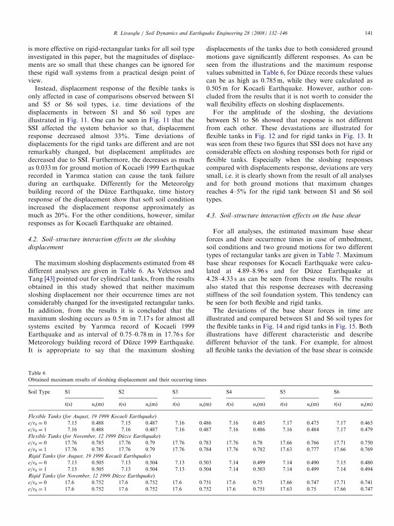
The maximum sloshing displacements estimated from 48different analyses are given in Table 6. As Veletsos andTang [43] pointed out for cylindrical tanks, from the resultsobtained in this study showed that neither maximumsloshing displacement nor their occurrence times are notconsiderably changed for the investigated rectangular tanks.In addition, from the results it is concluded that themaximum sloshing occurs as 0.5m in 7.17 s for almost allsystems excited by Yarımca record of Kocaeli 1999Earthquake and as interval of 0.75–0.78m in 17.76 s forMeteorology building record of Duzce 1999 Earthquake.It is appropriate to say that the maximum sloshing
Table 6
Obtained maximum results of sloshing displacement and their occurring times
Soil Type S1 S2 S3
t(s) us(m) t(s) us(m) t(s) us(
Flexible Tanks (for August, 19 1999 Kocaeli Earthquake)
e/r0 ¼ 0 7.15 0.488 7.15 0.487 7.16 0.4
e/r0 ¼ 1 7.16 0.488 7.16 0.487 7.16 0.4
Flexible Tanks (for November, 12 1999 Duzce Earthquake)
e/r0 ¼ 0 17.76 0.785 17.76 0.79 17.76 0.7
e/r0 ¼ 1 17.76 0.785 17.76 0.79 17.76 0.7
Rigid Tanks (for August, 19 1999 Kocaeli Earthquake)
e/r0 ¼ 0 7.13 0.505 7.13 0.504 7.13 0.5
e/r0 ¼ 1 7.13 0.505 7.13 0.504 7.13 0.5
Rigid Tanks (for November, 12 1999 Duzce Earthquake)
e/r0 ¼ 0 17.6 0.752 17.6 0.752 17.6 0.7
e/r0 ¼ 1 17.6 0.752 17.6 0.752 17.6 0.7
displacements of the tanks due to both considered groundmotions gave significantly different responses. As can beseen from the illustrations and the maximum responsevalues submitted in Table 6, for Duzce records these valuescan be as high as 0.785m, while they were calculated as0.505m for Kocaeli Earthquake. However, author con-cluded from the results that it is not worth to consider thewall flexibility effects on sloshing displacements.For the amplitude of the sloshing, the deviations
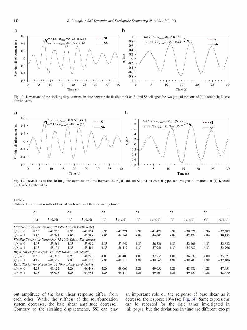
between S1 to S6 showed that response is not differentfrom each other. These devastations are illustrated forflexible tanks in Fig. 12 and for rigid tanks in Fig. 13. Itwas seen from these two figures that SSI does not have anyconsiderable effects on sloshing responses both for rigid orflexible tanks. Especially when the sloshing responsescompared with displacements response, deviations are verysmall, i.e. it is clearly shown from the result of all analysesand for both ground motions that maximum changesreaches 4–5% for the rigid tank between S1 and S6 soiltypes.
4.3. Soil–structure interaction effects on the base shear
For all analyses, the estimated maximum base shearforces and their occurrence times in case of embedment,soil conditions and two ground motions for two differenttypes of rectangular tanks are given in Table 7. Maximumbase shear responses for Kocaeli Earthquake were calcu-lated at 4.89–8.96 s and for Duzce Earthquake at4.28–4.33 s as can be seen from these results. The resultsalso stated that this response decreases with decreasingstiffness of the soil foundation system. This tendency canbe seen for both flexible and rigid tanks.The deviations of the base shear forces in time are
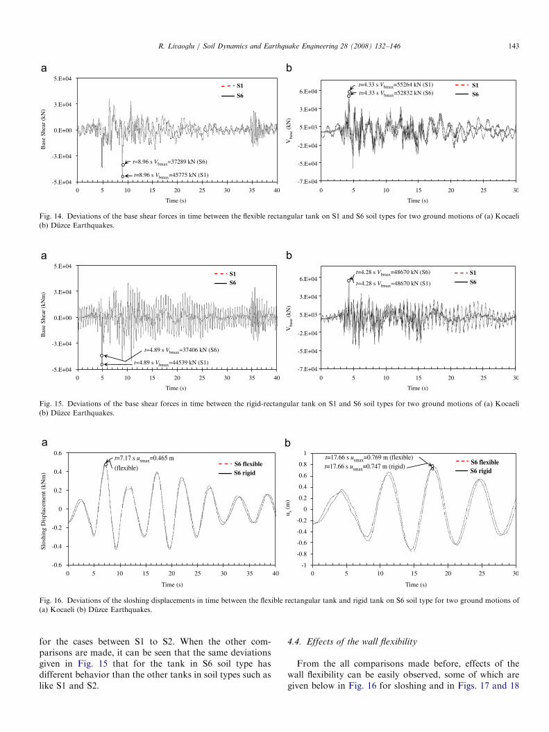
illustrated and compared between S1 and S6 soil types forthe flexible tanks in Fig. 14 and rigid tanks in Fig. 15. Bothillustrations have different characteristic and describedifferent behavior of the tank. For example, for almostall flexible tanks the deviation of the base shear is coincide
S4 S5 S6
m) t(s) us(m) t(s) us(m) t(s) us(m)
86 7.16 0.485 7.17 0.475 7.17 0.465
87 7.16 0.486 7.16 0.484 7.17 0.479
83 17.76 0.78 17.66 0.766 17.71 0.750
84 17.76 0.782 17.63 0.777 17.66 0.769
03 7.14 0.499 7.14 0.490 7.15 0.480
04 7.14 0.503 7.14 0.499 7.14 0.494
51 17.6 0.75 17.66 0.747 17.71 0.741
52 17.6 0.751 17.63 0.75 17.66 0.747
ARTICLE IN PRESS
-0.6
-0.4
-0.2
0
0.2
0.4
0.6
0 10 15 20 25 30 35 40
Slos
hing
dis
plac
emen
t (m
)
Time (s) Time (s)
t=7.15 s usmax=0.488 m (S1) t=7.17 s usmax=0.465 m (S6)
S1
S6
-1-0.8-0.6-0.4-0.2
00.20.40.60.8
1
0 10 15 20 25 30
u s (
m)
S1
S6
5 5
t=17.76 s usmax=0.78 m (S1)
t=17.71s usmax=0.75m (S6)
Fig. 12. Deviations of the sloshing displacements in time between the flexible tank on S1 and S6 soil types for two ground motions of (a) Kocaeli (b) Duzce
Earthquakes.
-0.8
-0.6
-0.4
-0.2
0
0.2
0.4
0.6
0.8
1
0 10 15 20 25 30
u s (
m)
-0.6
-0.4
-0.2
0
0.2
0.4
0.6
0 10 15 20 25 30 35 40
Time (s)
t=7.13 s usmax=0.505 m (S1) t=7.15 s usmax=0.480 m (S6)
S1
S6
Slos
hing
dis
plac
emen
t (m
)
t=17.76 s usmax=0.75 m (S1)
t=17.71s usmax=0.74m (S6)
Time (s)
S1
S6
5 5
Fig. 13. Deviations of the sloshing displacements in time between the rigid tank on S1 and on S6 soil types for two ground motions of (a) Kocaeli
(b) Duzce Earthquakes.
Table 7
Obtained maximum results of base shear forces and their occurring times
S1 S2 S3 S4 S5 S6
t(s) Vb(kN) t(s) Vb(kN) t(s) Vb(kN) t(s) Vb(kN) t(s) Vb(kN) t(s) Vb(kN)
Flexible Tanks (for August, 19 1999 Kocaeli Earthquake)
e/r0 ¼ 0 8.96 �45,775 8.96 �45,874 8.96 �47,271 8.96 �41,476 8.96 �38,520 8.96 �37,289
e/r0 ¼ 1 8.96 �45,763 8.96 �45,798 8.96 �46,163 8.96 �46,605 8.96 �42,424 8.96 �39,353
Flexible Tanks (for November, 12 1999 Duzce Earthquake)
e/r0 ¼ 0 4.33 55,264 4.33 55,689 4.33 57,849 4.33 56,326 4.33 52,108 4.33 52,832
e/r0 ¼ 1 4.33 55,174 4.33 55,404 4.33 56,417 4.33 57,956 4.33 55,882 4.33 52,996
Rigid Tanks (for August, 19 1999 Kocaeli Earthquake)
e/r0 ¼ 0 8.95 �43,333 8.96 �44,248 4.88 �40,400 4.89 �37,755 4.88 �36,837 4.88 �35,021
e/r0 ¼ 1 4.89 �44,539 8.95 �44,176 8.96 �40,113 4.88 �39,565 4.88 �38,803 4.88 �37,406
Rigid Tanks (for November, 12 1999 Duzce Earthquake)
e/r0 ¼ 0 4.33 47,122 4.28 48,448 4.28 49,067 4.28 49,055 4.28 48,585 4.28 47,951
e/r0 ¼ 1 4.33 48,033 4.28 46,991 4.28 49,470 4.28 49,107 4.28 49,153 4.28 48,670
R. Livaoglu / Soil Dynamics and Earthquake Engineering 28 (2008) 132–146142
but amplitude of the base shear response differs fromeach other. While, the stiffness of the soil/foundationsystem decreases, the base shear amplitude decreases.Contrary to the sloshing displacements, SSI can play
an important role on the response of base shear as itdecreases the response 19% (see Fig. 14). Same expressionscan be repeated for the rigid tanks investigated inthis paper, but the deviations in time are different except
ARTICLE IN PRESS
-7.E+04
-5.E+04
-2.E+04
5.E+03
3.E+04
6.E+04
0
Vba
se (
kN)
-5.E+04
-3.E+04
0.E+00
3.E+04
5.E+04
Bas
e Sh
ear
(kN
)
S1
S6
S1
S6
t=8.96 s Vbmax=37289 kN (S6)
t=8.96 s Vbmax=45775 kN (S1)
t=4.33 s Vbmax=55264 kN (S1)t=4.33 s Vbmax=52832 kN (S6)
Time (s)
5 10 15 20 25 300
Time (s)
5 10 15 20 25 30 35 40
Fig. 14. Deviations of the base shear forces in time between the flexible rectangular tank on S1 and S6 soil types for two ground motions of (a) Kocaeli
(b) Duzce Earthquakes.
-7.E+04
-5.E+04
-2.E+04
5.E+03
3.E+04
6.E+04
0
Vba
se (
kN)
-5.E+04
-3.E+04
0.E+00
3.E+04
5.E+04
Bas
e Sh
ear
(kN
m)
S1S6
S1
S6
t=4.89 s Vbmax=37406 kN (S6)
t=4.89 s Vbmax=44539 kN (S1)
t=4.28 s Vbmax=48670 kN (S6)
t=4.28 s Vbmax=48670 kN (S1)
Time (s)
5 10 15 20 25 300
Time (s)
5 10 15 20 25 30 35 40
Fig. 15. Deviations of the base shear forces in time between the rigid-rectangular tank on S1 and S6 soil types for two ground motions of (a) Kocaeli
(b) Duzce Earthquakes.
0-0.6
-0.4
-0.2
0.4
0.2
0
0.6
-0.6
-0.8
-1
-0.4
-0.2
0.4
0.2
0
0.6
0.8
1
S6 flexibleS6 rigid
S6 flexibleS6 rigid
t=17.66 s usmax=0.769 m (flexible)t=7.17 s usmax=0.465 mt=17.66 s usmax=0.747 m (rigid)
Time (s)
5 10 15 20 25 300
Time (s)
5 10 15 20 25 30 35 40
Slos
hing
Dis
plac
emen
t (kN
m)
u s (m
)
(flexible)
Fig. 16. Deviations of the sloshing displacements in time between the flexible rectangular tank and rigid tank on S6 soil type for two ground motions of
(a) Kocaeli (b) Duzce Earthquakes.
R. Livaoglu / Soil Dynamics and Earthquake Engineering 28 (2008) 132–146 143
for the cases between S1 to S2. When the other com-parisons are made, it can be seen that the same deviationsgiven in Fig. 15 that for the tank in S6 soil type hasdifferent behavior than the other tanks in soil types such aslike S1 and S2.
4.4. Effects of the wall flexibility
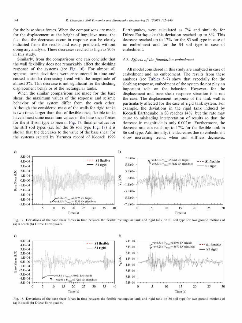
From the all comparisons made before, effects of thewall flexibility can be easily observed, some of which aregiven below in Fig. 16 for sloshing and in Figs. 17 and 18
ARTICLE IN PRESSR. Livaoglu / Soil Dynamics and Earthquake Engineering 28 (2008) 132–146144
for the base shear forces. When the comparisons are madefor the displacement at the height of impulsive mass, thefact that the decreases occur in response can be clearlyindicated from the results and easily predicted, withoutdoing any analysis. These decreases reached as high as 90%in this study.
Similarly, from the comparisons one can conclude thatthe wall flexibility does not remarkably affect the sloshingresponse of the systems (see Fig. 16). For almost allsystems, same deviations were encountered in time andcaused a similar decreasing trend with the magnitude ofalmost 3%. This decrease is not significant for the sloshingdisplacement behavior of the rectangular tanks.
When the similar comparisons are made for the baseshear, the maximum values of the response and seismicbehavior of the system differ from the each other.Although the considered mass of the walls for rigid tanksis two times larger than that of flexible ones, flexible tankshave almost same maximum values of the base shear forcesfor the stiff soil type as seen in Fig. 17. Smaller values forthe stiff soil types (i.e. for the S6 soil type Fig. 18) it isshown that the decreases to the value of the base shear forthe systems excited by Yarımca record of Kocaeli 1999
Vb
(kN
)
-5.E+04
-4.E+04
-3.E+04
-2.E+04
-1.E+04
0.E+00
1.E+04
2.E+04
3.E+04
4.E+04
5.E+04
0 5 10 15 20 25 30 35 40
Bas
e Sh
ear
(kN
)
S1 flexibleS1 rigid
Time (s)
t=8.96 s Vbmax=45775 kN (rigid)t=8.95 s Vbmax=43333 kN (flexible)
Fig. 17. Deviations of the base shear forces in time between the flexible rect
(a) Kocaeli (b) Duzce Earthquakes.
V (
kN)
-5.E+04-4.E+04-3.E+04-2.E+04-1.E+040.E+001.E+042.E+043.E+044.E+045.E+04
0 5 10 15 20 25 30 35 40
Bas
e Sh
ear
(kN
)
S1 flexibleS1 rigid
Time (s)
t=4.88 s Vbmax=35021 kN (rigid)
t=8.96 s Vbmax=37289 kN (flexible)
Fig. 18. Deviations of the base shear forces in time between the flexible rect
(a) Kocaeli (b) Duzce Earthquakes.
Earthquakes, were calculated as 7% and similarly forDuzce Earthquake this deviation reached up to 8%. Thisdecrease reached up to 17% for the S3 soil type in case ofno embedment and for the S4 soil type in case ofembedment.
4.5. Effects of the foundation embedment
All model considered in this study are analyzed in case ofembedment and no embedment. The results from theseanalyses (see Tables 5–7) show that especially for thesloshing response, embedment of the system do not play animportant role on the behavior. However, for thedisplacement and base shear response situation it is notthe case. The displacement response of the tank wall isparticularly affected for the case of rigid tank system. Forexample, the deviations in the rigid tank induced byKocaeli Earthquake in S3 reaches 14%, but the rate maycause to misleading interpretation of results so that thedecrease in magnitude is only 0.002m. Furthermore, thedecrease rate can reach up to 17% for the flexible tank inS6 soil type. Additionally, the decreases due to embedmentshow increasing trend, when soil stiffness decreases.
-7.E+04
-5.E+04
-3.E+04
-1.E+04
1.E+04
3.E+04
5.E+04
7.E+04
0 5 10 15 20 25 30
Time (s)
S1 flexibleS1 rigid
t=4.33 s Vbmax=55264 kN (rigid) t=3.33 s Vbmax=47122 kN (flexible)
angular tank and rigid tank on S1 soil type for two ground motions of
-7.E+04
-5.E+04
-3.E+04
-1.E+04
1.E+04
3.E+04
5.E+04
7.E+04
0 5 10 15 20 25 30
b
Time (s)
S1 flexibleS1 rigid
t=4.33 s Vbmax=52996 kN (rigid) t=4.28 s Vbmax=48670 kN (flexible)
angular tank and rigid tank on S6 soil type for two ground motions of
ARTICLE IN PRESSR. Livaoglu / Soil Dynamics and Earthquake Engineering 28 (2008) 132–146 145
Finally, it can be noted that embedment generally increasethe base shear forces, however, soil conditions seemed tohave a minor effect.
5. Conclusions
For the fast evaluation of the seismic behavior of therectangular tanks, a simple procedure including fluid–structure and soil–structure interaction effects is proposed.The procedure provides not only an estimation of the baseshears, overturning moments and displacements of thesystem but also the sloshing displacement. A computerprogram was also coded for the seismic analysis ofrectangular tanks considering these interaction effects.Furthermore an analysis with this procedure needs lesscomputational efforts.
Based on the above-mentioned analysis procedures anddiscussions on the results following conclusions can be drawn:
1.
The displacement responses generally changed, whensoil gets softer. For the rigid-rectangular tanks, rate ofthe deviations becomes larger than the flexible one.However, the changes in the displacement values arenegligible for the rigid tanks. For the flexible tanks onthe effect on the behavior is more pronounced and hasto be considered in the design. Therefore, for the flexibletanks SSI effect should be accounted for but for the rigidtank this effect may be negligible.2.
The sloshing responses are not practically affected byembedment, wall flexibility, and SSI parameters. Theseeffects on sloshing displacements can be ignored in theevaluation of the seismic behavior of the rectangulartanks. After all, for the flexible tank, sloshing displace-ment is smaller than that for the rigid tank and theembedment cause a little more increase on the sloshingdisplacement.3.
SSI and the flexibility of the tank walls affect the baseshear response of the systems. After all, the embedmentincreases the base shear, but it has less effect on theincreases in base shear than the other parameters. As aconsequence of this study, it was seen that the rigid tankcase has generally smaller base shear forces than theflexible case does although the masses of rigid tankswalls are two times larger than the masses of flexibletank.4.
It was seen that the results obtained for rectangular tankin relatively stiff soils (like S1 and S2) overestimateradiation damping in the lower-frequency range. Also, itshould be noted that soil–structure interaction has lessimportance in such soil conditions.Acknowledgments
The present work is supported by Grant-in-Aid forScientific Research (Project No.105M252) from the Scientificand Technological Research Council of Turkey (TUBITAK).
References
[1] Priestley MJN, Davidson BJ, Honey GD, Hopkins DC, Martin RJ,
Ramsey G, et al. Seismic design of storage tanks: recommendation of
a study group. New Zealand: the New Zealand Society for Earth-
quake Engineering; 1986. p. 180.
[2] Hoskins LM, Jacobsen LS. Water pressure in a tank caused by
simulated earthquake. Bull Seismol Soc Am 1934;24:1–32.
[3] Graham EW, Rodriguez AM. Characteristics of fuel motion which
affect airplane dynamics. J Appl Mech 1952;19:381–8.
[4] Housner GW. Dynamic pressures on accelerated fluid containers.
Bull Seism Soc Am 1957;47:15–35.
[5] Housner GW. Dynamic behaviour of water tanks. Bull Seism Soc Am
1963;53:381–7.
[6] Epstein HI. Seismic design of liquid storage tanks. J Struct Div ASCE
1976;102:1659–73.
[7] Bauer HF, Eidel W. Non-linear hydroelstic vibrations in rectangular
containers. Institut fur Raumfahrttechnik, Forschungsbericht: LRT-
WE-9-FB-7. 1987.
[8] Lepettier TG, Raichlen F. Non linear oscillation in rectangular tanks.
J Engng Mech 1998;114:1–23.
[9] Haroun MA, Chen W. Seismic large amplitude liquid sloshing
theory. In: Proceedings of the Sessions Related to Seismic Engng. Al
Structures Congree Vol. 89, 1989. p. 418–27.
[10] Haroun MA. Stress analysis of rectangular walls under seismically
induced hydrodynamic loads. Bull Seism Soc Am 1984;74:1031–41.
[11] Minowa C. Dynamic analysis of rectangular tanks. In: Proceedings of
7th WCEE, Istanbul, 1980. p. 447–50.
[12] Dogangun A, Durmus- A. Ayvaz Y. Finite element analysis of seismic
response of rectangular tanks using added mass and Lagrangian
approach. In: Proceedings of the second international conference on
civil Engineering. Computer applications research and practice. vol. I,
Bahrain, April 6–8, 1996. p. 371–9.
[13] Dogangun A, Durmus- A, Ayvaz Y. Earthquake analysis of flexible
rectangular tanks using the Lagrangian fluid finite element. Euro J
Mech A/Solids 1997;16:165–82.
[14] Kim JK, Park JY, Jin BM. The effects of soistructure ınteraction on
the dynamics of 3-D flexible rectangular tanks. In: Proceedings of the
sixth East Asia-Pacific conference on structural engineering. and
construction, January 14–16, Taipei, Taiwan, 1998.
[15] Dogangun A, Livaoglu R. Hydrodynamic pressures acting on the
walls of rectangular fluid containers,. Int J Struct Eng Mech
2004;17(2):203–14.
[16] Minowa C. Experimental studies of aseismic properties of various
type water tanks. In: Proceedings of eighth WCEE, San Francisco,
1984. p. 945–52.
[17] Koh HM, Kim JK, Park JH. Fluid–structure interaction analysis of
3-D rectangular tanks by a variationally coupled BEM-FEM and
comparison with test results. Earthquake Eng Struct Dyn 1998;27:
109–24.
[18] Park JH, Koh HM, Kim JK. Seismic isolation of pool-type tanks for
the storage of nuclear spent fuel assemblies. Nucl Eng Des
2000;199:143–54.
[19] Anghileri M, Castelletti LML, Tireli M. Fluid–structure interaction
of water filled tanks during the impact with the ground. Int J Impact
Eng 2005;31:235–54.
[20] Haroun MA, Ellaithy MH. Seismically induced fluid forces on
elevated tanks. J Tech Topics Civil Eng 1985;111(1):1–15.
[21] Veletsos AS, Meek JM. Dynamics of behaviour of building-
foundation systems. Earthquake Eng Struct Dyn 1974;3:121–38.
[22] Aviles J, Suarez M. Effective periods and damping of building-
foundation systems including seismic wave effects. Eng Struct 2002;
24:553–62.
[23] Veletsos SA, Prasad MA, Tang Y. Design approaches for soil
structure interaction, National Center for Earthquake Engineering
Research. Technical report NCEER-88-00331, 1988.
ARTICLE IN PRESSR. Livaoglu / Soil Dynamics and Earthquake Engineering 28 (2008) 132–146146
[24] FEMA 368. The 2000 NEHRP recommended provisions for new
buildings and other structures Part 1: Provision, 2000.
[25] FEMA 369. The 2000 NEHRP recommended provisions for new
buildings and other structures Part 2: Commentary, 2000.
[26] Eurocode-8. Design of structures for earthquake resistance—Part 4
(Draft No:2): silos, tanks and pipelines. European Committee for
Standardization, 2003. p. 65
[27] Aviles J, Perez-Rocha EL. Effect of foundation embedment during
building-soil structure interaction. Earthquake Eng Struct Dyn
1998;27:1523–40.
[28] Takewaki I, Takeda N, Uetani K. Fast practical evaluation of
soil–structure interaction of embedded structure. Soil Dyn Earth-
quake Eng 2003;23:195–202.
[29] Livaoglu R, Dogangun A. Seismic evaluation of fluid–elevated
tank–foundation/soil systems in frequency domain. Struct Eng Mech
2005;21(1):101–19.
[30] Wolf JP, Song CH. Finite-element modeling of unbounded media.
Chichester: Wiley; 1996.
[31] Wolf JP. The scaled boundary element method. New York: Wiley;
2003.
[32] Wolf JP, Meek JW. Cone models for homogeneous soil. J Geotech
Eng ASCE 1992;118:686–703.
[33] Wolf JP, Meek JW. Cone models for a soil layer on a flexible rock
half-space. Earthquake Eng Struct Dyn 1993;22:185–93.
[34] Wolf JP. Foundation vibration analysis using simple physical models.
Englewood Cliffs: Prentice-Hall; 1994.
[35] Kobori T, Minai R, Suzuki T. The dynamic ground compliance of a
rectangular foundation on a viscoelastic stratum, 20. Bulletin
Disaster Prevention Research Institute, Kyoto University; 1971.
p. 289–329.
[36] Gazetas G. Formulas and charts for impedance of surface and
embedded foundations. J Geotech Eng ASCE 1991;117:1363–81.
[37] Dobry R, Gazetas G. Dynamic response of arbitrarily-shaped
foundations. ASCE. Geotech Eng Div J 1986;113(2):109–35.
[38] Gazetas G, Tassoulas JL. Horizontal stiffness of arbitrarily-shaped
embedded foundations. ASCE Geotech Eng Div J 1987;113(5):
440–57.
[39] Chopra KA. Dynamics of structures: theory and applications to
earthquake engineering. Prentice-Hall International Inc; 2000.
[40] Bardet PJ. Experimental soil mechanics. Upper Saddle River, New
Jersey: 07458, Prentice Hall; 1997.
[41] Coduto PD. Foundation design: principles and practices. 2nd ed.
Upper Saddle River, New Jersey: Prentice Hall; 2001.
[42] SAT-2005. A Computer program for seismic analysis of rectangular
tanks considering fluid–structure–soil interaction. Karadeniz Techni-
cal University; 2005.
[43] Veletsos AS, Tang Y. Soil-structure interaction effects laterally
excited liquid storage tanks. Earthquake Eng Struct Dyn 1990;19:
473–96.