Embed Size (px)
Citation preview

Investigation of shape recovery stress for ferrous shape memory alloy
H. Naoi1, M. Wada2, T. Koike2, H. Yamamoto2 & T. Maruyama3 1Faculty of Engineering, Hosei University, Japan 2Graduate School of Engineering, Hosei University, Japan 3Awaji Materia Co. Ltd., Japan
Abstract
Ferrous shape memory alloy has recently been developed. The shape recovery characteristics of Fe-28%Mn-6%Si-5%Cr shape memory alloy are reported by uni-axially pre-strained test. The alloy has drawn strong attention for application for structural components such as steel pipe joints and crane rail joints. In order to apply the alloy to the joints, we estimate the joint strength for its structural design. So investigation of shape recovery stress has been significant. In this study, Fe-28%Mn-6%Si-5%Cr alloy are melted. Thin plates are manufactured by rolling and are heat-treated as solution treatment. We conduct the uniaxial test for evaluation of shape recovery stress. Specimens of the plates are pulled to the designated strain in the longitudinal direction by tensile test equipment. They are heated for shape recovery and simultaneously the pulling load is controlled at the value of zero until the displacement reaches to the designated value. After reaching at the designated value of displacement, the specimen is fully restricted without displacement. And the stress induced in the specimen is measured during heating up to over austenitic transformation temperature and cooling down to room temperature. Stress - strain - temperature diagrams are measured through the heating and cooling process. We conclude that the stress induced by restriction increases with the increase of restricted strain. Keywords: ferrous shape memory alloy, shape recovery stress, uni-axially pre-strained, pipe joints, solution treatment, austenitic transformation, restricted strain, ε martensite transformation, shape recovery strain.
Computational Methods and Experimental Measurements XIV 485
© 2009 WIT PressWIT Transactions on Modelling and Simulation, Vol 48, www.witpress.com, ISSN 1743-355X (on-line) doi:10.2495/CMEM090441
1 Introduction
Ferrous shape memory alloy is more low-cost than non-ferrous shape memory alloy of the Ti-Ni etc. and its formability is more excellent. The application of the alloy to fittings for tubing, screws for tightening, and joints for structural connection has been investigated (Wada et al. [3]). In the practical use of the ferrous shape memory alloy, the shape recovery strain and the shape recovery stress are important. Here, it is defined with the shape recovery stress as the stress which is caused in the shape memory alloy when shape recovery strain is restrained by controlling displacement. When displacement is restrained almost completely, the shape recovery stress in the alloy is assumed to be roughly 200-250MPa or less. The appearance mechanism of the shape recovery stress is not yet clarified. In the practical use, the displacement is often restricted on the way of shape recovery process, so the relationship between the shape recovery stress and the restricted strain under various conditions is investigated.
2 Characteristic of ferrous shape memory alloy
2.1 Mechanical properties and transformation temperatures
Fe-28%Mn-6%Si-5%Cr alloy (mass %) is used for the test specimens. They are rolled out to the thin plate of the thickness 0.8mm. The longitudinal direction where the test specimen is rolled out is defined as LD and the transversal direction of the plate width are defined as TD. Afterwards, they are air-cooled in 950C with the heating of one hour as the solution treatment for the shape-memory treatment. Mechanical characteristics of the test specimen are measured (Wada et al. [4]) in the direction of LD and TD, as shown in Table 1.
Table 1: Mechanical property in Fe-28%Mn-6%Si-5%Cr shape memory alloy.
In the each direction, 0.2% proof stress is 271MPa and 267MPa, the tensile strength is 815MPa and 811MPa, and the elongation is 38.6% and 37.9%, respectively. The plasticity anisotropy is little observed to the test specimens.
486 Computational Methods and Experimental Measurements XIV
© 2009 WIT PressWIT Transactions on Modelling and Simulation, Vol 48, www.witpress.com, ISSN 1743-355X (on-line)
The martensitic transformation beginning temperature is observed at from 253K to 298K, and the austenitic transformation finishing temperature is observed at from 403K to 458K.
2.2 Deformation behaviour in the shape recovery process at uni-axially prestrained test
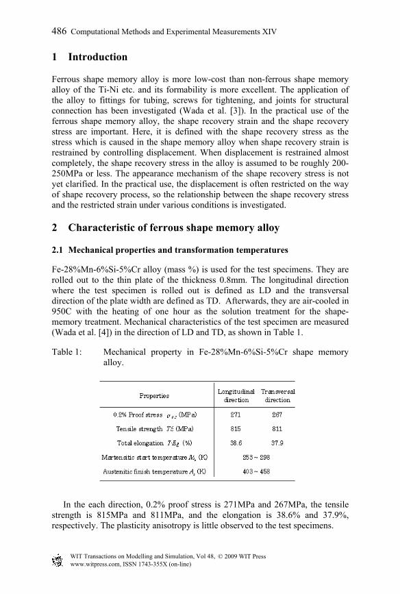
Fig. 1 shows the schematic of stress-strain and temperature-strain curve in the shape recovery process at uniaxial test. The strain worked by plastic deformation to the specimen which is expanded in this report is defined as εp of prestrain, and the strain measured by the change of the gauge length before and after the heat treatment is defined as εr of shape recovery strain. When the alloy is applied to a fixed amount of deformation and is heated at a fixed temperature repeatedly, larger shape recovery strain will be developed. This phenomenon is called training effect.
Figure 1: Stress-strain and temperature strain diagram in shape recovery
process.
It is reported that the shape recovery strains of Fe-28%Mn-6%Si-5%Cr alloy are measured in the case of without training and with training by tensile prestrain and compressive prestrain, as shown in fig.2. In the uniaxially-prestrained specimens, the prestrain εr increases to the maximum value of -2% at 6% εp, and then decreases slightly with increasing prestrain εp. The slight reduction of εr above 6% εp may be attributed to the slip bands generated by greater deformation, since it is reported (Otsuka et al. [6]) that the maximum volume fraction of the stress-induced martensite phase is approximately 30% in the alloy. The absolute shape recovery strains at compressive prestrain are lower than that of at tensile prestrain because of different deformation behaviour by friction force. As there is little friction force at the tensile prestrain, the state of stress is estimated to be uniaxial.
Computational Methods and Experimental Measurements XIV 487
© 2009 WIT PressWIT Transactions on Modelling and Simulation, Vol 48, www.witpress.com, ISSN 1743-355X (on-line)
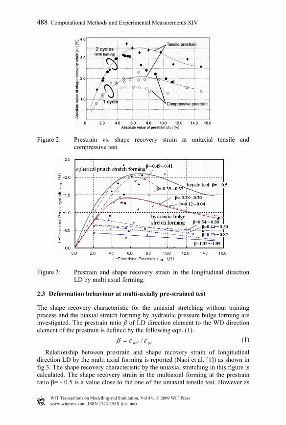
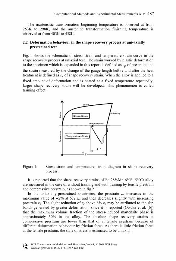
Figure 2: Prestrain vs. shape recovery strain at uniaxial tensile and compressive test.
Figure 3: Prestrain and shape recovery strain in the longitudinal direction
LD by multi axial forming.
2.3 Deformation behaviour at multi-axially pre-strained test
The shape recovery characteristic for the uniaxial stretching without training process and the biaxial stretch forming by hydraulic pressure bulge forming are investigated. The prestrain ratio β of LD direction element to the WD direction element of the prestrain is defined by the following eqn. (1).
pLpW εεβ /= (1)
Relationship between prestrain and shape recovery strain of longitudinal direction LD by the multi axial forming is reported (Naoi et al. [1]) as shown in fig.3. The shape recovery characteristic by the uniaxial stretching in this figure is calculated. The shape recovery strain in the multiaxial forming at the prestrain ratio β= - 0.5 is a value close to the one of the uniaxial tensile test. However as
488 Computational Methods and Experimental Measurements XIV
© 2009 WIT PressWIT Transactions on Modelling and Simulation, Vol 48, www.witpress.com, ISSN 1743-355X (on-line)
the prestrain ratio β increases the absolute value of the shape recovery strain εrl decreases. This reason is considered (Wada et al. [2]) that a complete dislocation is introduced and the shape recovery behaviour is interrupted when the supply of an excessive strain more than the strain that makes the stress-induced martensitic transformation appear to this alloy.
3 Shape recovery stress for uniaxial tensile test
3.1 Experimental procedure
3.1.1 Test specimen The ferrous shape memory alloy of Fe-28%Mn-6%Si-5%Cr is used for the test specimen. After melting and solidification, plates of 0.8mm in thickness are manufactured by rolling. Tensile test specimens are machined at 100mm in length, 19mm in width and 0.8mm in thickness. Then, as for both shape memory heat treatment and solution treatment, furnace heating at 1000C for 1hour and air cooling is conducted. In order to prevent the thermal transfer to the tensile test equipment at the heating of shape recovery treatment, ceramics of 5mm in thickness is bonded to the chuck part of tensile test specimen as heat insulator. Thereinafter the prestrain is given and the shape recovering treatment is conducted. Tensile prestrain of from 5.5 to 6% is given to the specimen by tensile equipment.
3.1.2 Shape recovery heat treatment and restriction of displacement Shape recovery heat treatment and restriction of displacement for specimen are conducted by the experimental equipment. The heat insulator is installed at the top and bottom part of the band heater in order to heat the tensile test specimen at uniform and constant temperature. Heating and cooling rate are controlled at 12C/minute and 6C/minute, respectively. After the test specimen is prestrained by the tensile test machine, the specimen is installed and clamped in the equipment. The stress and strain of the specimen can be controlled at designated value in the equipment. At the first stage, the stress of the specimen is controlled to be free of zero and the strain of the specimen is measured by position meter. Then at the second stage of designated interval time, the displacement of the specimen is completely restricted during heating and cooling down as shape recovery treatment. The axial load which is generated during the shape recovery treatment is measured by the load cell, and uniaxial stress is calculated. The experimental condition is set at three kind states of the restraint of displacement. Firstly the displacement by shape recovery is completely restricted from the first stage of heating, secondly it is restricted in the middle of shape recovery process and thirdly it is free from restriction.
3.2 Results and discussion
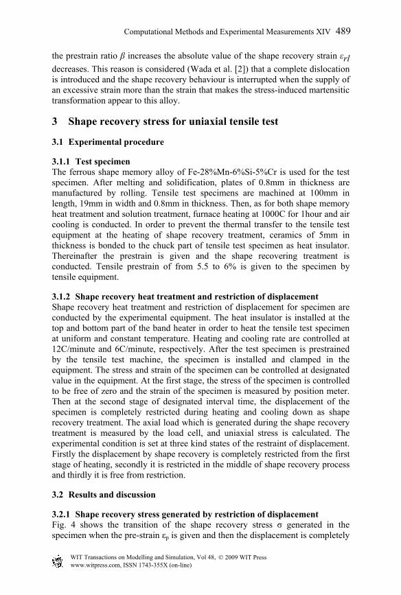
3.2.1 Shape recovery stress generated by restriction of displacement Fig. 4 shows the transition of the shape recovery stress σ generated in the specimen when the pre-strain εp is given and then the displacement is completely
Computational Methods and Experimental Measurements XIV 489
© 2009 WIT PressWIT Transactions on Modelling and Simulation, Vol 48, www.witpress.com, ISSN 1743-355X (on-line)
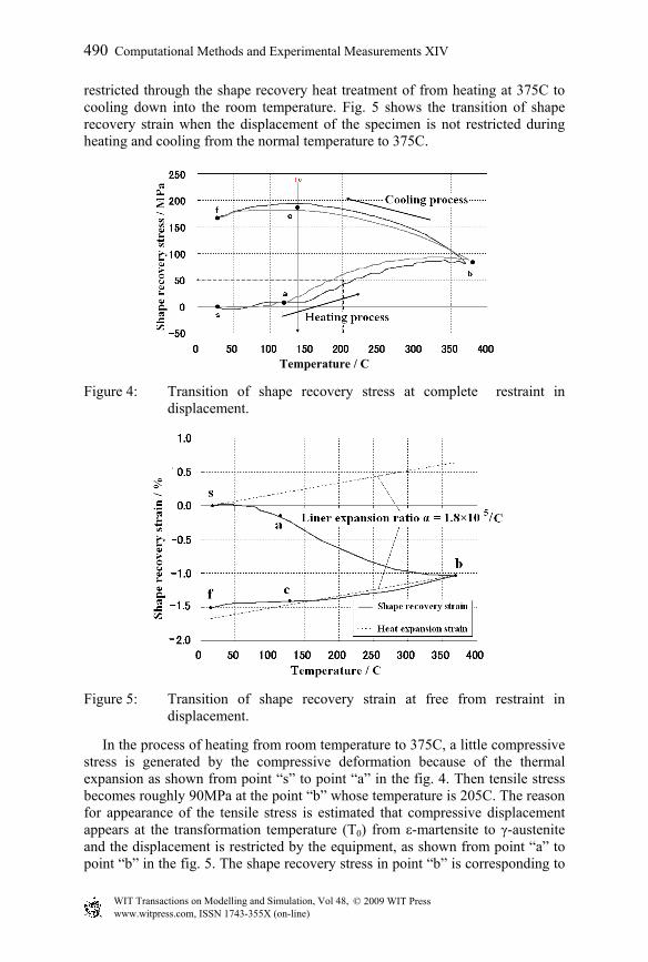
restricted through the shape recovery heat treatment of from heating at 375C to cooling down into the room temperature. Fig. 5 shows the transition of shape recovery strain when the displacement of the specimen is not restricted during heating and cooling from the normal temperature to 375C.
Temperature / C
Figure 4: Transition of shape recovery stress at complete restraint in displacement.
Figure 5: Transition of shape recovery strain at free from restraint in displacement.
In the process of heating from room temperature to 375C, a little compressive stress is generated by the compressive deformation because of the thermal expansion as shown from point “s” to point “a” in the fig. 4. Then tensile stress becomes roughly 90MPa at the point “b” whose temperature is 205C. The reason for appearance of the tensile stress is estimated that compressive displacement appears at the transformation temperature (T0) from ε-martensite to γ-austenite and the displacement is restricted by the equipment, as shown from point “a” to point “b” in the fig. 5. The shape recovery stress in point “b” is corresponding to
© 2009 WIT PressWIT Transactions on Modelling and Simulation, Vol 48, www.witpress.com, ISSN 1743-355X (on-line)
490 Computational Methods and Experimental Measurements XIV
the fluid stress which is generated by the uniaxial compression strain of about -1% at 375C shown in the fig. 5. According to our research in the past, when the stress whose direction is opposite to that of shape recovery strain is added to the material, the absolute value of the shape recovery strain decreases. So the shape recovery compressive strain decreases because the experiment from point “a” to point “b” is conducted under the tensile stress. Therefore, the fluid stress by the plastic forming is considered to be gradually suppressed. The stress generated by the thermal shrink increases with the progress of cooling process from 348C to 130C of the transformation temperature T0, as shown from point “b” to “c” in the fig. 5. The shape recovery stress is saturated to be about 200MPa at 130C of the transformation temperature (T0) and after then the generated stress decreases slightly. The phenomenon of the cooling process performs as well as those of the heating process. The shape recovery stress from point “c” to point “f” slightly decreases. The reason is considered the transformation of from the γ-austenite to the ε-martensite that appears under the stress generated by the restricted strain. The generated internal stress and the chemical free energy are considered to be balanced during the cooling process. Namely, when the specimen is exposed in the tensile stress the ε-martensite is stable at over the temperature of T0 and the γ-austenite is stable at under the temperature of T0. The reason of the decrease in the stress is also considered Bauschinger effect, because the tensile deformation is performed after the compressive one in this shape recovery process.
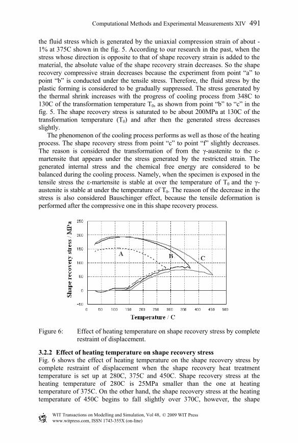
Figure 6: Effect of heating temperature on shape recovery stress by complete
restraint of displacement.
3.2.2 Effect of heating temperature on shape recovery stress Fig. 6 shows the effect of heating temperature on the shape recovery stress by complete restraint of displacement when the shape recovery heat treatment temperature is set up at 280C, 375C and 450C. Shape recovery stress at the heating temperature of 280C is 25MPa smaller than the one at heating temperature of 375C. On the other hand, the shape recovery stress at the heating temperature of 450C begins to fall slightly over 370C, however, the shape
Computational Methods and Experimental Measurements XIV 491
© 2009 WIT PressWIT Transactions on Modelling and Simulation, Vol 48, www.witpress.com, ISSN 1743-355X (on-line)
recovery stress after cooling is almost equal with the one heated at 375C.The stress generated by the thermal stress decreases with the increasing temperature rise because its γ austenite transformation performs completely over the heating temperature of 360C. Namely, shape recovery stress is maximum value when the heat treatment temperature is over 360C.
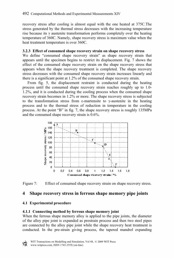
3.2.3 Effect of consumed shape recovery strain on shape recovery stress We define “consumed shape recovery strain” as shape recovery strain that appears until the specimen begins to restrict its displacement. Fig. 7 shows the effect of the consumed shape recovery strain on the shape recovery stress that appears when the shape recovery treatment is completed. The shape recovery stress decreases with the consumed shape recovery strain increases linearly and there is a significant point at 1.2% of the consumed shape recovery strain. From fig. 5, the displacement restraint is conducted during the heating process until the consumed shape recovery strain reaches roughly up to 1.0-1.2%, and it is conducted during the cooling process when the consumed shape recovery strain becomes in 1.2% or more. The shape recovery stress is subjected to the transformation stress from ε-martensite to γ-austenite in the heating process and to the thermal stress of reduction in temperature in the cooling process. At the point “B” in fig. 7, the shape recovery stress is roughly 135MPa and the consumed shape recovery strain is 0.6%.
Figure 7: Effect of consumed shape recovery strain on shape recovery stress.
4 Shape recovery stress in ferrous shape memory pipe joints
4.1 Experimental procedure
4.1.1 Connecting method by ferrous shape memory joint When the ferrous shape memory alloy is applied to the pipe joints, the diameter of the alloy pipe joint is expanded as prestrain process and then two steel pipes are connected by the alloy pipe joint while the shape recovery heat treatment is conducted. In the pre-strain giving process, the tapered mandrel expanding
492 Computational Methods and Experimental Measurements XIV
© 2009 WIT PressWIT Transactions on Modelling and Simulation, Vol 48, www.witpress.com, ISSN 1743-355X (on-line)
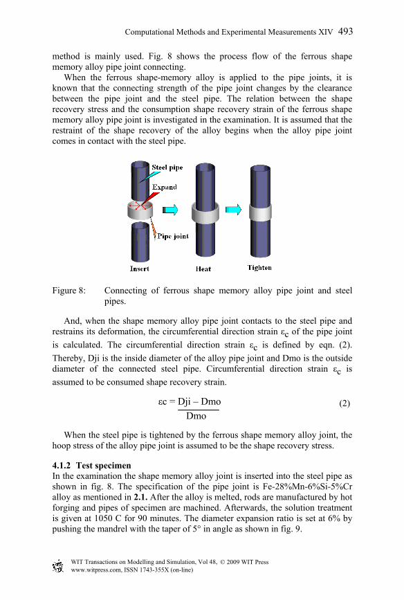
method is mainly used. Fig. 8 shows the process flow of the ferrous shape memory alloy pipe joint connecting. When the ferrous shape-memory alloy is applied to the pipe joints, it is known that the connecting strength of the pipe joint changes by the clearance between the pipe joint and the steel pipe. The relation between the shape recovery stress and the consumption shape recovery strain of the ferrous shape memory alloy pipe joint is investigated in the examination. It is assumed that the restraint of the shape recovery of the alloy begins when the alloy pipe joint comes in contact with the steel pipe.
Figure 8: Connecting of ferrous shape memory alloy pipe joint and steel pipes.
And, when the shape memory alloy pipe joint contacts to the steel pipe and restrains its deformation, the circumferential direction strain εc of the pipe joint is calculated. The circumferential direction strain εc is defined by eqn. (2). Thereby, Dji is the inside diameter of the alloy pipe joint and Dmo is the outside diameter of the connected steel pipe. Circumferential direction strain εc is assumed to be consumed shape recovery strain.
(2)
When the steel pipe is tightened by the ferrous shape memory alloy joint, the hoop stress of the alloy pipe joint is assumed to be the shape recovery stress.
4.1.2 Test specimen In the examination the shape memory alloy joint is inserted into the steel pipe as shown in fig. 8. The specification of the pipe joint is Fe-28%Mn-6%Si-5%Cr alloy as mentioned in 2.1. After the alloy is melted, rods are manufactured by hot forging and pipes of specimen are machined. Afterwards, the solution treatment is given at 1050 C for 90 minutes. The diameter expansion ratio is set at 6% by pushing the mandrel with the taper of 5° in angle as shown in fig. 9.
εc = Dji – Dmo Dmo
Computational Methods and Experimental Measurements XIV 493
© 2009 WIT PressWIT Transactions on Modelling and Simulation, Vol 48, www.witpress.com, ISSN 1743-355X (on-line)
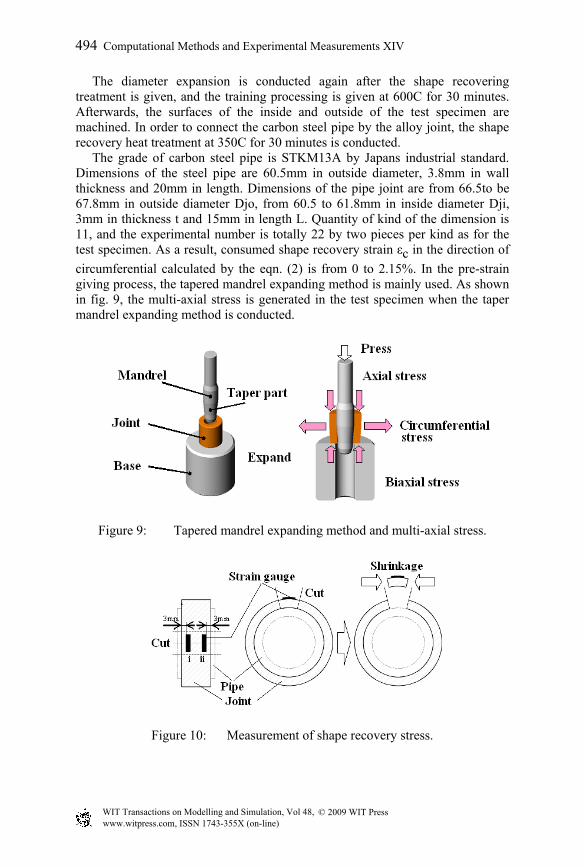
The diameter expansion is conducted again after the shape recovering treatment is given, and the training processing is given at 600C for 30 minutes. Afterwards, the surfaces of the inside and outside of the test specimen are machined. In order to connect the carbon steel pipe by the alloy joint, the shape recovery heat treatment at 350C for 30 minutes is conducted. The grade of carbon steel pipe is STKM13A by Japans industrial standard. Dimensions of the steel pipe are 60.5mm in outside diameter, 3.8mm in wall thickness and 20mm in length. Dimensions of the pipe joint are from 66.5to be 67.8mm in outside diameter Djo, from 60.5 to 61.8mm in inside diameter Dji, 3mm in thickness t and 15mm in length L. Quantity of kind of the dimension is 11, and the experimental number is totally 22 by two pieces per kind as for the test specimen. As a result, consumed shape recovery strain εc in the direction of circumferential calculated by the eqn. (2) is from 0 to 2.15%. In the pre-strain giving process, the tapered mandrel expanding method is mainly used. As shown in fig. 9, the multi-axial stress is generated in the test specimen when the taper mandrel expanding method is conducted.
Figure 9: Tapered mandrel expanding method and multi-axial stress.
Figure 10: Measurement of shape recovery stress.
494 Computational Methods and Experimental Measurements XIV
© 2009 WIT PressWIT Transactions on Modelling and Simulation, Vol 48, www.witpress.com, ISSN 1743-355X (on-line)
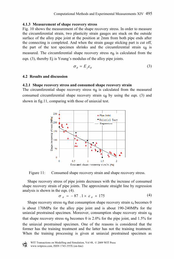
4.1.3 Measurement of shape recovery stress Fig. 10 shows the measurement of the shape recovery stress. In order to measure the circumferential strain, two plasticity strain gauges are stuck on the outside surface of the alloy pipe joint at the position at 2mm from both pipe ends after the connecting is completed. And when the strain gauge sticking part is cut off, the part of the test specimen shrinks and the circumferential strain εθ is measured. The circumferential shape recovery stress σθ is calculated from the eqn. (3), thereby Ej is Young’s modulus of the alloy pipe joints.
θθ εσ jE= (3)
4.2 Results and discussion
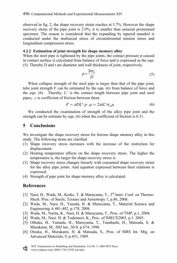
4.2.1 Shape recovery stress and consumed shape recovery strain The circumferential shape recovery stress σθ is calculated from the measured consumed circumferential shape recovery strain εθ by using the eqn. (3) and shown in fig.11, comparing with those of uniaxial test.
Figure 11: Consumed shape recovery strain and shape recovery stress.
Shape recovery stress of pipe joints decreases with the increase of consumed shape recovery strain of pipe joints. The approximate straight line by regression analysis is shown in the eqn. (4).
(4)
Shape recovery stress σθ that consumption shape recovery strain εθ becomes 0 is about 170MPa for the alloy pipe joint and is about 190-240MPa for the uniaxial prestrained specimen. Moreover, consumption shape recovery strain εθ that shape recovery stress σθ becomes 0 is 2.0% for the pipe joint, and 1.5% for the uniaxial prestrained specimen. One of the reasons is considered that the former has the training treatment and the latter has not the training treatment. When the training processing is given at uniaxial prestrained specimen as
1751.87 +×−= θθ εσ
Computational Methods and Experimental Measurements XIV 495
© 2009 WIT PressWIT Transactions on Modelling and Simulation, Vol 48, www.witpress.com, ISSN 1743-355X (on-line)
Dtp θσ2
=
observed in fig. 2, the shape recovery strain reaches at 3.7%. However the shape recovery strain of the pipe joint is 2.0%, it is smaller than uniaxial prestrained specimen. The reason is considered that the expanding by tapered mandrel is conducted under the multiaxial stress of circumferential tension stress and longitudinal compression stress.
4.2.2 Estimation of joint strength for shape memory alloy When the steel pipe is tightened by the pipe joints, the contact pressure p caused in contact surface is calculated from balance of force and is expressed as the eqn. (5). Thereby D and t are diameter and wall thickness of joint, respectively.
(5)
When collapse strength of the steel pipe is larger than that of the pipe joint, tube joint strength F can be estimated by the eqn. (6) from balance of force and the eqn. (6). Thereby, L’ is the contact length between pipe joint and steel pipes, μis coefficient of friction between them.
µσπµπ θ'2' tLpDLF =⋅⋅= (6)
We conducted the examination of strength of the alloy pipe joint and the strength can be estimate by eqn. (6) when the coefficient of friction is 0.31.
5 Conclusions
We investigate the shape recovery stress for ferrous shape memory alloy in this study. The following items are clarified. (1) Shape recovery stress increases with the increase of the restriction for
displacement. (2) Heating temperature affects on the shape recovery stress. The higher the
temperature is, the larger the shape recovery stress is. (3) Shape recovery stress changes linearly with consumed shape recovery strain
for the alloy pipe joints. And equation expressed between their relations is expressed.
(4) Strength of pipe joint for shape memory alloy is calculated.
References
[1] Naoi, H., Wada, M., Koike, T. & Maruyama, T., 3rd.Inter. Conf. on Thermo-Mech. Proc. of Steels, Texture and Anisotropy 1, p.86, 2008.
[2] Wada, M., Naoi, H., Yasuda, H. & Maruyama, T., Material Science and Engineering A 481-482, p.178, 2008.
[3] Wada, M., Narita, K., Naoi, H. & Maruyama, T., Proc. of TMP, p.1, 2004. [4] Wada, M., Naoi. H. & Tsukimori, K., Proc. of IMECE2003, p.1. 2003. [5] Othuka, H., Yamada, H., Maruyama, T., Tanahashi, H., Matsuda, S. &
Murakami, M., ISIJ Int., 30-8, p.674, 1990. [6] Otsuka, H., Murakami, H. & Matsuda, S., Proc. of MRS Int. Mtg. on
Advanced Materials, 9, p.451, 1989.
496 Computational Methods and Experimental Measurements XIV
© 2009 WIT PressWIT Transactions on Modelling and Simulation, Vol 48, www.witpress.com, ISSN 1743-355X (on-line)