Embed Size (px)
Citation preview

IOP PUBLISHING and INTERNATIONAL ATOMIC ENERGY AGENCY NUCLEAR FUSION
Nucl. Fusion 49 (2009) 104010 (12pp) doi:10.1088/0029-5515/49/10/104010
Investigation of steady-state tokamakissues by long pulse experiments on ToreSupraG. Giruzzi, R. Abgrall3, L. Allegretti, J.M. Ane, P. Angelino, T. Aniel, A. Argouarch,J.F. Artaud, S. Balme, V. Basiuk, P. Bayetti, A. Becoulet, M. Becoulet,L. Begrambekov14, M.S. Benkadda16, F. Benoit, G. Berger-by, B. Bertrand,P. Beyer16, J. Blum9, D. Boilson15, H. Bottollier-Curtet, C. Bouchand, F. Bouquey,C. Bourdelle, F. Bremond4, S. Bremond, C. Brosset, J. Bucalossi, Y. Buravand,P. Cara, S. Carpentier, A. Casati, O. Chaibi, M. Chantant, P. Chappuis, M. Chatelier,G. Chevet, D. Ciazynski, G. Ciraolo17, F. Clairet, J. Clary, L. Colas, Y. Corre,X. Courtois, N. Crouseilles6, G. Darmet, M. Davi, R. Daviot, H. De Esch, J. Decker,P. Decool, E. Delchambre, E. Delmas, L. Delpech, C. Desgranges, P. Devynck,L. Doceul, N. Dolgetta, D. Douai, H. Dougnac, J.L. Duchateau, R. Dumont,G. Dunand, A. Durocher, A. Ekedahl, D. Elbeze, L.G. Eriksson, A. Escarguel16,F. Escourbiac, F. Faisse, G. Falchetto, M. Farge10, J.L. Farjon, N. Fedorczak,C. Fenzi-Bonizec, X. Garbet, J. Garcia, J.L. Gardarein, L. Gargiulo, P. Garibaldi,E. Gauthier, A. Geraud, T. Gerbaud, M. Geynet, P. Ghendrih, C. Gil, M. Goniche,V. Grandgirard, C. Grisolia, G. Gros, A. Grosman, R. Guigon, D. Guilhem,B. Guillerminet, R. Guirlet, J. Gunn, S. Hacquin, J.C. Hatchressian, P. Hennequin12,D. Henry, C. Hernandez, P. Hertout, S. Heuraux11, J. Hillairet, G.T. Hoang,S.H. Hong, C. Honore12, J. Hourtoule, M. Houry, T. Hutter, P. Huynh, G. Huysmans,F. Imbeaux, E. Joffrin, J. Johner, J.Y. Journeaux, F. Jullien, F. Kazarian, M. Kocan,B. Lacroix, V. Lamaison, J. Lasalle, G. Latu6, Y. Lausenaz, C. Laviron, C. Le Niliot7,M. Lennholm, F. Leroux, F. Linez, M. Lipa, X. Litaudon, T. Loarer, F. Lott, P. Lotte,J.F. Luciani2, H. Lutjens2, A. Macor, S. Madeleine, P. Magaud, P. Maget, R. Magne,L. Manenc, Y. Marandet16, G. Marbach, J.L. Marechal, C. Martin16, V. Martin4,A. Martinez, J.P. Martins, R. Masset, D. Mazon, L. Meunier, O. Meyer, L. Million,M. Missirlian, R. Mitteau, P. Mollard, V. Moncada, P. Monier-Garbet, D. Moreau,P. Moreau, M. Nannini, E. Nardon, H. Nehme, C. Nguyen, S. Nicollet, M. Ottaviani,D. Pacella1, S. Pamela, T. Parisot, H. Parrat, P. Pastor, A.L. Pecquet, B. Pegourie,V. Petrzilka5, Y. Peysson, C. Portafaix, M. Prou, N. Ravenel, R. Reichle, C. Reux,P. Reynaud, M. Richou, F. Rigollet7, F. Rimini, H. Roche, S. Rosanvallon, J. Roth13,P. Roubin16, R. Sabot, F. Saint-Laurent, S. Salasca, T. Salmon, F. Samaille,A. Santagiustina, B. Saoutic, Y. Sarazin, J. Schlosser, K. Schneider17, M. Schneider,F. Schwander , J.L. Segui, J. Signoret, A. Simonin, S. Song, E. Sonnendruker6,P. Spuig, L. Svensson, P. Tamain, M. Tena, J.M. Theis, M. Thonnat4, A. Torre,J.M. Travere, E. Trier12, E. Tsitrone, F. Turco, J.C. Vallet, A. Vatry, L. Vermare12,F. Villecroze, D. Villegas, D. Voyer8, K. Vulliez, W. Xiao, D. Yu, L. Zani, X.L. Zou andW. Zwingmann
CEA, IRFM, F-13108 St Paul-lez-Durance, France1 Associazione EURATOM-ENEA sulla Fusione, C.R. Frascati, Roma, Italy2 CPT, Ecole Polytechnique, 91128 Palaiseau, France3 INRIA–CNRS:UMR5800–CNRS:UMR5466, Universite Sciences et Technologies, Bordeaux, France4 INRIA Sophia-Antipolis, 2004 Route des Lucioles BP 93, 06902 Sophia Antipolis, France5 IPP, Association EURATOM/IPP.CR, Za Solvankou 3, PO Box 17, 18221 Prague, Czech Republic6 IRMA, Universite Louis Pasteur, Strasbourg, France7 IUSTI–CNRS, University of Provence, Marseille, France8 Laboratoire Ampere (UMR CNRS 5005), Universite de Lyon, Ecole Centrale de Lyon, Ecully, France
0029-5515/09/104010+12$30.00 1 © 2009 IAEA, Vienna Printed in the UK

Nucl. Fusion 49 (2009) 104010 G. Giruzzi et al
9 LJAD, U.M.R. C.N.R.S. No 6621, Universite de Nice, Sophia, Antipolis10 LMD–CNRS, Ecole Normale Superieure, Paris, France11 LPMIA, CNRS (UMR 7040), Universite Henri Poincare, France12 LPTP, Ecole Polytechnique, 91128 Palaiseau, France13 Max-Planck-Institut fur Plasmaphysik, EURATOM Association, 85748 Garching, Germany14 Moscow Physics and Engineering Institute (MEPhI), 31 Karhirskoe Sh, 115409 Moscow, Russia15 School of Physical Sciences, Dublin City University, Glasnevin, EI-Dublin 9, Ireland16 Universite de Provence/CNRS, Physique des Interactions Ioniques et Moleculaires, UMR 6633, Marseille, France17 MSNM-GP, UMR 6181–CNRS/Universite Paul Cezanne, Marseille, France
Received 27 November 2008, accepted for publication 17 Mar 2009Published 9 September 2009Online at stacks.iop.org/NF/45
AbstractThe main results of the Tore Supra experimental programme in the years 2007–2008 are reported. They documentsignificant progress achieved in the domain of steady-state tokamak research, as well as in more general issuesrelevant for ITER and for fusion physics research. Three areas are covered: ITER relevant technology developmentsand tests in a real machine environment, tokamak operational issues for high power and long pulses, and fusionplasma physics. Results presented in this paper include test and validation of a new, load-resilient concept ofion cycotron resonance heating antenna and of an inspection robot operated under ultra-high vacuum and hightemperature conditions; an extensive experimental campaign (5 h of plasma) aiming at deuterium inventory andcarbon migration studies; real-time control of sawteeth by electron cyclotron current drive in the presence of fastion tails; ECRH-assisted plasma start-up studies; dimensionless scalings of transport and turbulence; transportexperiments using active perturbation methods; resistive and fast-particle driven MHD studies. The potential roleof Tore Supra in the worldwide fusion programme before the start of ITER operation is also discussed.
PACS numbers: 52.55.Fa, 52.55.Rk, 52.50.Sw, 52.50.Qt, 52.35.Ra, 52.25.Fi, 52.70.Kz
(Some figures in this article are in colour only in the electronic version)
1. Introduction
Twenty years after the start of its operation (April 1988),Tore Supra remains the only large tokamak fully equipped forsteady-state operation, combining superconducting magneticcoils, actively cooled plasma facing components (PFCs) andnon-inductive current drive capability. Its primary mission,the investigation of physics and technology issues of steady-state tokamak operation, retains all its scientific interest andrelevance to the fusion programme. After the attainmentof the symbolic target of discharges with 1 GJ of injectedenergy (>6 min duration) [1], the next initiative was thesystematic increase in the injected power (∼10 MW), onshorter discharges (∼20–30 s, but still significantly longer thanthe current redistribution time) [2]. This phase allows theexploration of an operational domain of the highest interestfor ITER and reactor applications: the combined use of ioncyclotron resonance heating (ICRH) and lower hybrid currentdrive (LHCD) systems at significant injected energy levelsposes specific problems of antenna–plasma edge interactions[3] that can presently be fully tackled on Tore Supra only. Thebonus of this class of experiments is related to the simultaneouspresence of electron and ion tails in plasmas at Ti ∼ Te,which allows the investigation of various ITER relevant fusionphysics subjects. Systematic operation of Tore Supra overthe past several years at high power levels for long pulseshas revealed growing limitations of the power that can besuccessfully coupled to the plasma. These limitations manifest
themselves as a steadily increasing disruptivity of discharges ofthe same type, which is believed to be related to the formationof carbon deposits on the PFC. The problem of high power,long pulse operation is therefore tightly related to another ITERrelevant subject that constitutes a major part of the Tore Suprascientific programme: erosion and re-deposition processes onPFC and the associated deuterium retention [4]. This was thesubject of a specific experimental campaign in 2007.
This work reports the main achievements of the ToreSupra programme in the last two years. Significant resultshave been obtained in three areas: ITER relevant technologydevelopments and tests in a real machine environment,tokamak operational issues for high power and long pulses,and experiments oriented to fusion plasma physics studies.The potential role of Tore Supra in the worldwide fusionprogramme before the start of ITER operation will also bediscussed.
2. Technology developments
Technology developments for ITER are naturally a significantpart of the fusion research proramme. In some cases, it isimportant to use an existing fusion machine as a test-bed forsuch developments, in order to check the compatibility witha real machine environment and with plasma operation. Inthis section, two examples of this type of use of Tore Supraare presented: an ITER-like prototype of ICRH antenna and anewly developed inspection robot.
2
Nucl. Fusion 49 (2009) 104010 G. Giruzzi et al
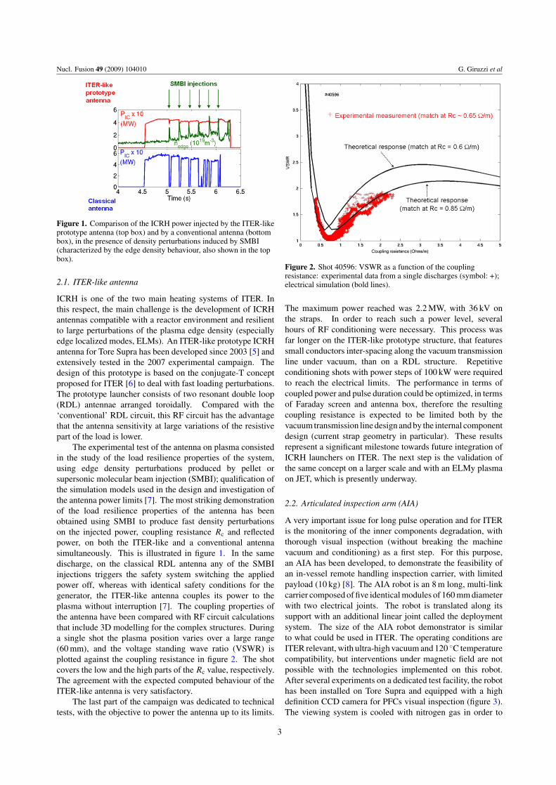
Figure 1. Comparison of the ICRH power injected by the ITER-likeprototype antenna (top box) and by a conventional antenna (bottombox), in the presence of density perturbations induced by SMBI(characterized by the edge density behaviour, also shown in the topbox).
2.1. ITER-like antenna
ICRH is one of the two main heating systems of ITER. Inthis respect, the main challenge is the development of ICRHantennas compatible with a reactor environment and resilientto large perturbations of the plasma edge density (especiallyedge localized modes, ELMs). An ITER-like prototype ICRHantenna for Tore Supra has been developed since 2003 [5] andextensively tested in the 2007 experimental campaign. Thedesign of this prototype is based on the conjugate-T conceptproposed for ITER [6] to deal with fast loading perturbations.The prototype launcher consists of two resonant double loop(RDL) antennae arranged toroidally. Compared with the‘conventional’ RDL circuit, this RF circuit has the advantagethat the antenna sensitivity at large variations of the resistivepart of the load is lower.
The experimental test of the antenna on plasma consistedin the study of the load resilience properties of the system,using edge density perturbations produced by pellet orsupersonic molecular beam injection (SMBI); qualification ofthe simulation models used in the design and investigation ofthe antenna power limits [7]. The most striking demonstrationof the load resilience properties of the antenna has beenobtained using SMBI to produce fast density perturbationson the injected power, coupling resistance Rc and reflectedpower, on both the ITER-like and a conventional antennasimultaneously. This is illustrated in figure 1. In the samedischarge, on the classical RDL antenna any of the SMBIinjections triggers the safety system switching the appliedpower off, whereas with identical safety conditions for thegenerator, the ITER-like antenna couples its power to theplasma without interruption [7]. The coupling properties ofthe antenna have been compared with RF circuit calculationsthat include 3D modelling for the complex structures. Duringa single shot the plasma position varies over a large range(60 mm), and the voltage standing wave ratio (VSWR) isplotted against the coupling resistance in figure 2. The shotcovers the low and the high parts of the Rc value, respectively.The agreement with the expected computed behaviour of theITER-like antenna is very satisfactory.
The last part of the campaign was dedicated to technicaltests, with the objective to power the antenna up to its limits.
Figure 2. Shot 40596: VSWR as a function of the couplingresistance: experimental data from a single discharges (symbol: +);electrical simulation (bold lines).
The maximum power reached was 2.2 MW, with 36 kV onthe straps. In order to reach such a power level, severalhours of RF conditioning were necessary. This process wasfar longer on the ITER-like prototype structure, that featuressmall conductors inter-spacing along the vacuum transmissionline under vacuum, than on a RDL structure. Repetitiveconditioning shots with power steps of 100 kW were requiredto reach the electrical limits. The performance in terms ofcoupled power and pulse duration could be optimized, in termsof Faraday screen and antenna box, therefore the resultingcoupling resistance is expected to be limited both by thevacuum transmission line design and by the internal componentdesign (current strap geometry in particular). These resultsrepresent a significant milestone towards future integration ofICRH launchers on ITER. The next step is the validation ofthe same concept on a larger scale and with an ELMy plasmaon JET, which is presently underway.
2.2. Articulated inspection arm (AIA)
A very important issue for long pulse operation and for ITERis the monitoring of the inner components degradation, withthorough visual inspection (without breaking the machinevacuum and conditioning) as a first step. For this purpose,an AIA has been developed, to demonstrate the feasibility ofan in-vessel remote handling inspection carrier, with limitedpayload (10 kg) [8]. The AIA robot is an 8 m long, multi-linkcarrier composed of five identical modules of 160 mm diameterwith two electrical joints. The robot is translated along itssupport with an additional linear joint called the deploymentsystem. The size of the AIA robot demonstrator is similarto what could be used in ITER. The operating conditions areITER relevant, with ultra-high vacuum and 120 ◦C temperaturecompatibility, but interventions under magnetic field are notpossible with the technologies implemented on this robot.After several experiments on a dedicated test facility, the robothas been installed on Tore Supra and equipped with a highdefinition CCD camera for PFCs visual inspection (figure 3).The viewing system is cooled with nitrogen gas in order to
3

Nucl. Fusion 49 (2009) 104010 G. Giruzzi et al
Figure 3. The AIA inside Tore Supra, during an inspection inultra-vacuum and at 120 ◦C.
keep the embedded electronic temperature below 60 ◦C. Thetests of deployment in Tore Supra, under ultra-high vacuum(1.4 × 10⁻⁵ Pa) and at a temperature of 120 ◦C have beenperformed in September 2008. The main motivations of thisexperiment were the verification of the reliability of the armmovements and an extensive test of the outgassing of thewhole structure, which could cause pollution of the plasmain subsequent machine operation. The arm has been fullyunfold in the equatorial plane, with additional movementsupwards (inspection of an infrared (IR) endoscope shutter)and downwards (close inspection of the toroidal limiter).The duration of the deployment and inspection phase wasof the order of 6 h: during this time, the evolution of thevarious gases in the vacuum chamber has been continuouslymonitored by spectrometry analysis, without showing anysignificant variation. These tests [9] have been successful andhave demonstrated that previous baking of the arm at 200 ◦Cefficiently limits outgassing during the deployment inside themachine. After the deployment, normal plasma operation hasbeen possible without any particular wall conditioning.
3. Operational issues
3.1. Deuterium inventory
In-vessel tritium retention is a crucial issue for ITER sincea simple extrapolation of present measurements shows thatthe limit of 700 g set by nuclear licensing could be reachedwithin a few hundreds nominal discharges for the referencewall materials combination (carbon fibre composite at thedivertor target strike point/tungsten dome and upper divertortargets/beryllium first wall) [10]. Although the generaltrends regarding hydrogenic retention are well established andobserved in many devices, the relative contributions of theunderlying physical processes have not been clearly identifiedand retention rates deduced from integrated particle balance(∼10–20% of the injected gas, >30% in Tore Supra) aresignificantly larger than those estimated from post-mortemanalysis of the PFCs (∼3–4%) [11]. Comparing these twoestimates is difficult, since the former is generally basedon particle balance calculations for a limited number ofdischarges, whereas the latter integrates the whole history ofthe PFCs. To clarify where the missing deuterium is trapped,the best approach is to load the wall with deuterium in acontrolled discharge scenario until its inventory is known with
Figure 4. Pulse duration (a), number of UFOs per discharge (b) anddisruption frequency (c) versus discharge number. The vertical lineindicates the change in the heating scenario (from a squarewaveform to a continuous ramp of the LH power).
a sufficient accuracy from integrated particle balance, and thento dismantle some of the PFCs for analysis. Such a studywas undertaken on Tore Supra, in three phases: a dedicatedcampaign to load the PFCs with deuterium, the dismantling ofa toroidal limiter sector to extract selected samples, and then anextensive analysis programme on the samples, in collaborationwith European partners in the frame of the European PlasmaWall Interaction Task Force [12, 13].
At the start of the experiment, the vessel was carbonized,then boronized in order to mark the beginning of the experimentby a 13C-layer, easily identifiable in subsequent analysis,and for initial wall conditioning. A robust scenario wasdesigned to allow plasma duration long enough (∼2 min) forpermanent retention to be much larger than the transient one,namely average density 〈ne〉 = 1.5 × 10¹⁹ m−3, LH powerPLH = 2 MW, plasma current Ip = 0.6 MA and magneticfield BT = 3.8 T. Ten days of operation were devoted tothe D-loading of the wall (∼5 h of plasma, equivalent toapproximately 1 yr of normal operation). Neither of the otherexperimental programmes, nor wall conditioning were carriedout during this time. The main operational issue was linkedto the appearance of UFOs (i.e. large particles with a highimpurity content, detached from the wall, PFCs or antennas,and penetrating into the plasma), whose frequency increaseddramatically during the campaign, triggering a phase of plasmadetachment followed by a disruption in a number of cases[14, 15]. This is shown in figure 4, where the number ofUFOs per discharge is plotted versus the discharge number,showing an almost linear increase and a correlated decreaseof the plasma duration. In order to overcome this limitation,it became necessary to modify the LH power waveform, fromits initially constant value to a continuous ramp, from 1.2 to1.6–1.8 MW, and also to decrease the plasma duration down to∼80 s (this change corresponds to the vertical line in figure 4).The continuous increase of the UFO frequency is believed tobe related to the build-up of thick deposits in the shadowedregions of the toroidal surface—in the immediate vicinity ofthe confined plasma.
4

Nucl. Fusion 49 (2009) 104010 G. Giruzzi et al
Figure 5. Injected gas and wall D inventory versus cumulateddischarge duration for the dedicated campaign.
Figure 6. Breakdown of the D-content in the different zones (thickdeposits, thin deposits, erosion and gaps), as determined by TDSand NRA.
The main results of particle balance are presented infigure 5, where the injected gas and the wall D inventoryare plotted versus the cumulated discharge duration. Aconstant retention rate was measured (∼2 × 10²⁰ D s−1 in thestationary phase), with no sign of wall saturation, leadingto a total increment of the wall inventory of ∼3 × 1024 D(∼4 times the pre-campaign estimate). After dismantling asector of the toroidal limiter (20◦ toroidal), 40 CFC-tiles (outof a total number of 672 for the whole sector)—distributedover erosion, thin-deposit and thick-deposit zones—wereextracted for analysis. Thermodesorption (TDS) and nuclearreaction analysis (NRA) measurements of the D-content wereperformed on a first selection of tiles. These measurementsshowed surface D-concentration of ∼5% and ∼20% inthe eroded and deposition zones respectively, on a typicalthickness of 10 to 40 µm [12]. As shown in figure 6, onceextrapolated over the whole limiter, this corresponds to ∼50%of the total inventory, mainly determined by the depositionzones and gaps between tiles [13]. It is found that theretention process is dominated by codeposition; approximately10% of deuterium penetrates in the erosion zones, owingto the high porosity of the CFC material. These resultshave of course a strong impact on the subsequent choices ofdetritiation techniques, at least for carbon-based PFCs, sincesuch techniques will depend on the location of the deposits.
3.2. High power issues
The recent experimental campaigns have been particularlyintense in terms of injected power, energy and accumulated
plasma time (10 h plasma time in both 2006 and 2007,with 65 GJ injected RF energy in 2006 and 40 GJ in 2007).Significant experience has been gained in the understanding oflocalized heat loads due to RF sheath effects and interactionof fast particles [3, 14]. In addition to the previously discussedscenario with LH only, developed for D-retention studies, highpower scenarios have also been explored, combining LHCDand ICRH, at higher plasma current and density (IP = 0.9 MAand ne/nGr ∼ 0.8). During the 2006 campaign, this scenarioyielded ∼10 MW coupled for 26 s in repetitive discharges[14]. However, as in the D-retention campaign, an increasingoperational difficulty emerged, limiting the high power andlong pulse performance. The analyses undertaken suggest thatthe limitation is linked to the growth and flaking of re-depositedcarbon layers on the main PFC. This type of operational limitencountered on Tore Supra could represent a serious concernfor next step devices that operate repetitive discharges overlong durations, leading to re-deposited layers of significantthickness.
In order to understand the dynamics of these disruptivelimits, the pre-disruption behaviour of more than 140discharges from the 2006 and 2007 campaigns have beenanalysed [15], using IR imaging together with visible andultraviolet (UV) spectroscopy of impurities (carbon, iron andoxygen). The IR images reveal in several cases the appearanceof a small (∼ cm2) hot spot, clearly localized in a zone ofthick carbon re-deposition (>100 µm) on the main PFC, thetoroidal limiter. At the hot spot, the surface temperatureincreases by a few hundred degree celsius, lasting severaltime frames (>50 ms) until the plasma disruption. Ejectionof flakes from the re-deposition zones is observed by the IR aswell as CCD cameras and is associated with the formation of aMARFE. The most likely mechanism is the continuous growthof the carbon deposits, resulting from over 44 h accumulatedplasma time since the installation of the toroidal limiter in2000. As the deposits are heated up by plasma radiation,they tend to crack and partially detach from the surface,the thermal resistance between the deposits and the activelycooled surface increases, thus heating the deposits even further.Eventually, flaking occurs as a result of inner thermal stresses,and UFOs are formed. This mechanism, likely responsible forthe new operational limit encountered, does not seem specificto C-based PFCs: it could be found for other types of depositedlayers (e.g. Be), with bad thermal contact with the activelycooled PFC.
To validate this hypothesis, the carbon deposits on thePFCs were completely removed during the winter shutdown2007–2008. This was a complex intervention, lasting 10 days.It was performed by hand by four teams of two people,equipped with gas masks for protection against carbon dustinhalation, and using tungsten carbide scrapers and vacuumcleaners (∼0.8 kg of carbon has been recovered and is availablefor analysis). This thorough cleaning procedure had a dramaticimpact on the operation of the machine. After ohmic restart,LH, then ICRH power increase phases have been performed(this took typically four operation days, including antennaconditioning on plasma discharges). After a boronization,high power operation with combined LH and ICRH power wascommenced—usually a very lengthy procedure in the presenceof carbon deposits. This time, nine discharges were sufficient
5
Nucl. Fusion 49 (2009) 104010 G. Giruzzi et al
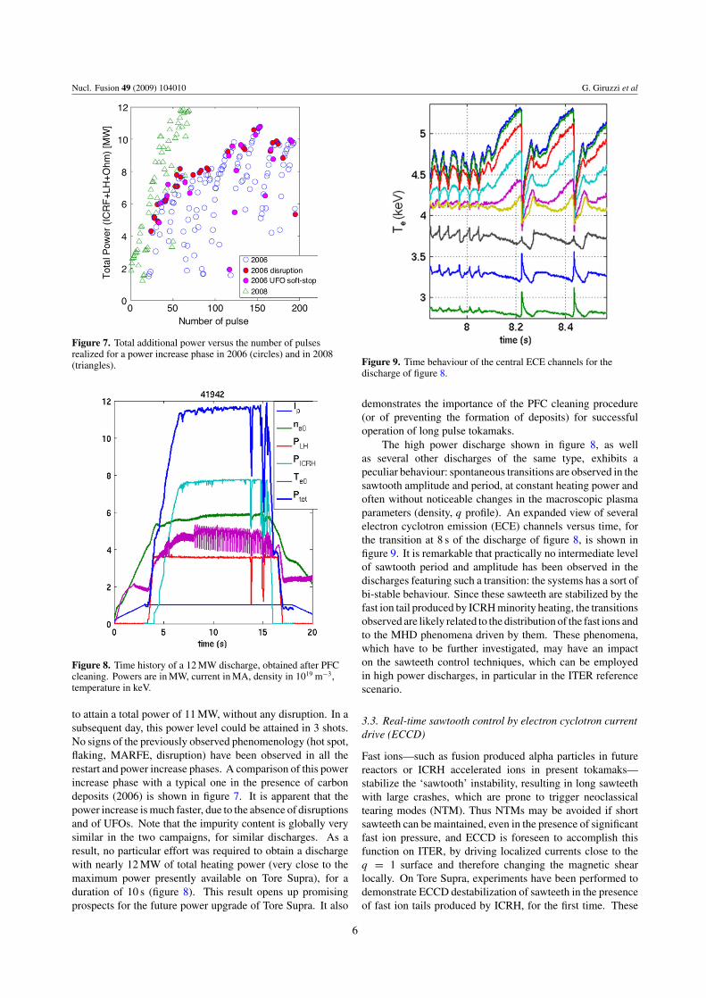
Figure 7. Total additional power versus the number of pulsesrealized for a power increase phase in 2006 (circles) and in 2008(triangles).
Figure 8. Time history of a 12 MW discharge, obtained after PFCcleaning. Powers are in MW, current in MA, density in 1019 m−3,temperature in keV.
to attain a total power of 11 MW, without any disruption. In asubsequent day, this power level could be attained in 3 shots.No signs of the previously observed phenomenology (hot spot,flaking, MARFE, disruption) have been observed in all therestart and power increase phases. A comparison of this powerincrease phase with a typical one in the presence of carbondeposits (2006) is shown in figure 7. It is apparent that thepower increase is much faster, due to the absence of disruptionsand of UFOs. Note that the impurity content is globally verysimilar in the two campaigns, for similar discharges. As aresult, no particular effort was required to obtain a dischargewith nearly 12 MW of total heating power (very close to themaximum power presently available on Tore Supra), for aduration of 10 s (figure 8). This result opens up promisingprospects for the future power upgrade of Tore Supra. It also
Figure 9. Time behaviour of the central ECE channels for thedischarge of figure 8.
demonstrates the importance of the PFC cleaning procedure(or of preventing the formation of deposits) for successfuloperation of long pulse tokamaks.
The high power discharge shown in figure 8, as wellas several other discharges of the same type, exhibits apeculiar behaviour: spontaneous transitions are observed in thesawtooth amplitude and period, at constant heating power andoften without noticeable changes in the macroscopic plasmaparameters (density, q profile). An expanded view of severalelectron cyclotron emission (ECE) channels versus time, forthe transition at 8 s of the discharge of figure 8, is shown infigure 9. It is remarkable that practically no intermediate levelof sawtooth period and amplitude has been observed in thedischarges featuring such a transition: the systems has a sort ofbi-stable behaviour. Since these sawteeth are stabilized by thefast ion tail produced by ICRH minority heating, the transitionsobserved are likely related to the distribution of the fast ions andto the MHD phenomena driven by them. These phenomena,which have to be further investigated, may have an impacton the sawteeth control techniques, which can be employedin high power discharges, in particular in the ITER referencescenario.
3.3. Real-time sawtooth control by electron cyclotron currentdrive (ECCD)
Fast ions—such as fusion produced alpha particles in futurereactors or ICRH accelerated ions in present tokamaks—stabilize the ‘sawtooth’ instability, resulting in long sawteethwith large crashes, which are prone to trigger neoclassicaltearing modes (NTM). Thus NTMs may be avoided if shortsawteeth can be maintained, even in the presence of significantfast ion pressure, and ECCD is foreseen to accomplish thisfunction on ITER, by driving localized currents close to theq = 1 surface and therefore changing the magnetic shearlocally. On Tore Supra, experiments have been performed todemonstrate ECCD destabilization of sawteeth in the presenceof fast ion tails produced by ICRH, for the first time. These
6

Nucl. Fusion 49 (2009) 104010 G. Giruzzi et al
Figure 10. Comparison of two consecutive shots––one with2.3 MW of ICRH and no ECCD and one with ECCD added. Fromtop to bottom: temperatures, sawtooth periods, ECCD and inversionradius locations, powers.
experiments include demonstration of co- and counter-ECCDeffects on the sawtooth period [16], as well as feedback controlof the sawtooth period by moving the steerable mirrors of theECCD antenna in real time [17], as foreseen in ITER. Anexample of the effect of ECCD on the sawtooth period is shownin figure 10. During the ICRH phase (PICRH = 2 MW) of a1 MA discharge, co-ECCD is applied (PECCD ≈ 0.2 MW) at atoroidal injection angle of 28◦, while the poloidal injectionangle is continuously swept from −3◦ to −8◦ in order tomove the driven current location through the q = 1 surface.This results in a strong and abrupt decrease of the sawtoothperiod in a well defined time window. For comparison, it isinteresting to consider the effect of counter-ECCD. Figure 11shows the sawtooth period as a function of the distance betweenthe inversion radius and the peak of the ECCD deposition,for a number of discharges, similar to the one shown infigure 10, with both co- and counter-current ECCD. Shorteningof the sawtooth period is achieved with the ECCD currentdriven inside and outside the q = 1 surface, for co-andcounter-ECCD, respectively. The lower panel of figure 11also shows that the ECCD has very little effect on the sawtoothperiod in ohmic plasmas. The abrupt switch of the sawtoothperiod is analogous to the bi-stable behaviour observed in thespontaneous transitions, which leads us to conjecture that, inthe presence of fast ions, other mechanisms in addition to theevolution of the shear at q = 1 must be invoked to explain theexperimental results.
In the present set of experiments a simple closed loopcontroller for real time control of the sawtooth period wasimplemented [17]. Such a control will be required in futuremachines for sawtooth destabilization to be a viable optionfor NTM avoidance. These experiments were successful inproving that the sawtooth period can be switched reliablybetween short and long sawteeth though they also highlightedthe difficulty associated with the abrupt change in sawtoothperiod. As shown in figure 12, the controller has not beenable to obtain an intermediate state between the long (∼70 ms)
(a)
(b)
Figure 11. Sawtooth period versus distance between the ECCDlocation and the inversion radius, for co- and counter-ECCD.(a) and (b) show the result with central ICRH and in ohmic plasma,respectively.
Figure 12. Feedback control of the sawtooth period using thepoloidal injection angle of the ECCD as an actuator. Note thatchanges of the sawtooth period after the end of the feedback phaseare due to variations of the ICRH power.
and the short (∼30 ms) sawtooth period. If this bi-stablebehaviour is universal—as it seems to be at present—thecontrol algorithms implemented on future tokamak devicesmust take this into account and better physics understandingof this phenomenon would be very helpful for the success ofsuch control schemes.
3.4. ECRH-assisted start-up
ECRH pre-ionization and assisted start-up will be necessaryin ITER [18]. The use of superconducting poloidal fieldcoils will limit the available toroidal electric field (ET �0.3 V m−1), while the presence of toroidally continuousvacuum-vessel structures will increase the magnetic ‘stray’field (axisymmetric poloidal fields normal to the toroidalfield BT) at breakdown. With this motivation, experimentsaiming at ECRH-assisted start-up for electric field values closeto the ITER limit have been performed on Tore Supra [19].ECRH at the 1st cyclotron harmonic, O-mode polarization(as presently foreseen in ITER) has been applied for typically
7

Nucl. Fusion 49 (2009) 104010 G. Giruzzi et al
Figure 13. Applied electric field versus pre-fill pressure for anumber of successful start-up attempts, both with and withoutECRH assistance. Open squares correspond to ohmic startup, fullcircles to ECRH-assisted startup. L is the toroidal connectionlength. Townsend curves are also shown.
50 ms, using one or two 118 GHz gyrotrons (PEC = 300–500 kW), at oblique injection (toroidal angle ∼30◦). The usualstart-up voltage on Tore Supra is 25 V (ET = 1.7 V m−1) withdeuterium pre-fill pressure around 20 mPa. The minimumstray field value (B∞) in most of the vacuum vessel islower than 5 mT, which gives toroidal connection lengths(L = aBT/B∞) longer than 770 m. In these conditions,pre-ionization was successfully achieved at the EC resonancelocation and <30 kA of current was established in 10 ms.Successful plasma initiation has been obtained down to<0.15 V m−1 at 7 mPa. ECRH-assisted start-up has also beenregularly employed at plasma restart after two machine shut-downs of several months, with major loss of conditioning dueto various operations inside the vacuum vessel, including PFCcleaning. ECRH has proven to be a very reliable and useful toolfor plasma start-up in such difficult conditions [19]. A globalplot of the successful start-up attempts at low loop voltage ispresented in figure 13. It appears that with ECRH startup at aglobally lower electric field is achieved.
4. Fusion physics-oriented experiments
4.1. Dimensionless scalings
A substantial amount of experimental time has been devotedto physics-oriented investigations. The basic dependences ofheat transport coefficients on dimensionless quantities (β, ρ∗
and ν∗) have been investigated in L-mode discharges in whichtwo of the three quantities were kept fixed, not only in theiraverage values but also, as far as possible, in their radialprofiles. The key feature of these studies is that turbulencemeasurements have been systematically performed in the samedischarges, using two types of reflectometers (fast sweepingand Doppler) [20]. In this way, global scaling laws have beencompared with those of the local transport coefficients and ofthe turbulence profiles. Results on the β scaling have beenpresented elsewhere [20, 21]. The main interest for studying
L-mode scaling laws is to compare them to H-mode scalingsdetermined e.g. in JT-60U [22], ASDEX Upgrade [23] and JET[24]. This allows one to identify the role of edge phenomena,such as ELMs and pedestal physics.
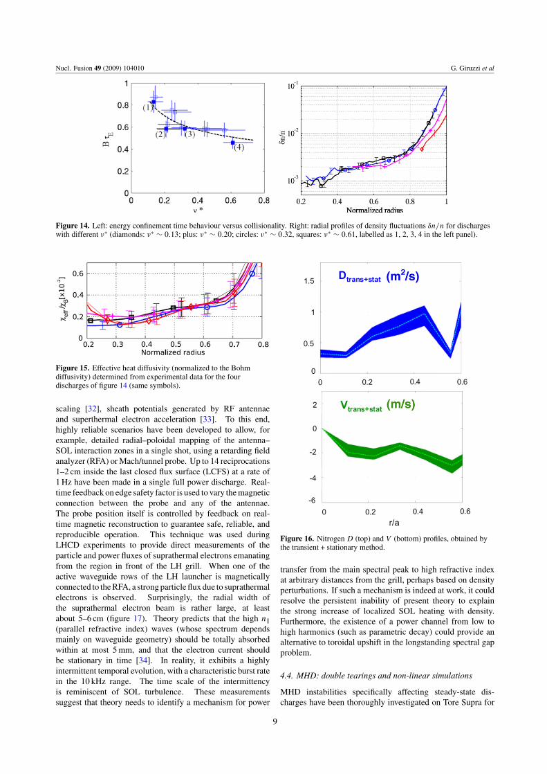
More recently, experiments have been carefully performedby varying the dimensionless collisionality parameter, ν∗, by afactor ∼4.5 [25]. This has been accomplished by magneticfield variations in the range 2.4–3.87 T, with appropriateadjustments of current and ICRH power, in order to keep q,β and ρ∗ fixed. Density fluctuations (δn/n), measured byboth reflectometers, are found to increase significantly whenincreasing ν∗ in the outer part of the plasma, as illustrated infigure 14 for four discharges characterized by values of ν∗ atmid-radius in the range 0.13–0.61. At the same time, the globalconfinement time degrades (B0τE ∝ ν∗−0.4±0.2). In contrast,there is no significant modification of δn/n in the central region(r/a < 0.7). A similar trend is found by local transportanalyses, shown in figure 15, where the heat diffusivitiesare represented using the same symbols as in figure 14. Ascompared with previous L-mode experiments performed inTFTR [26] and DIII-D [27] in which no dependence has beenfound, these new results exhibit a mild ν∗ dependence of theglobal confinement time. This behaviour suggests that the ν∗
dependence in L-mode may differ from a power law.
4.2. Perturbative transport studies
Transport studies using active perturbation methods have beencarried out, for heat, particles and impurities. In particular,ECRH power modulations at low frequency (1 Hz) have beenused to investigate the controversial subject of heat pinch,which has been observed in some experiments [28].
Perturbation techniques have also been used to study thedependence of impurity transport on the atomic number Z
and on electron heating. Different metallic impurities (in therange Z = 13–32) have been injected in ohmic, sawtooth-freeplasmas using laser blow-off techniques, and the associatedresponse has been observed on the soft x-ray tomographyand UV spectroscopy signals [29]. In ohmic discharges, theZ range has been extended by studying nitrogen transportusing SMBI of small traces of the impurity [30]. This allowsrepeated injections in the same pulse, reducing the statisticaluncertainties of the results, without increasing the injectedamount of atoms above the trace level. Combination of thesetransient measurements with standard stationary transportanalysis (which is used as a constraint on the pinch velocity todiffusion coefficient ratio V/D) has allowed further reductionon the uncertainty of the determination of both D and V ,as shown in figure 16. The experimental diffusion has beenfound to be anomalous everywhere and independent of Z;for nitrogen, the convection is inwards. Modelling usingthe quasilinear gyrokinetic code QuaLiKiz [31] predicts that(i) transport is governed by ITG turbulence even close to theplasma centre, (ii) the turbulent V (matching the experimentalprofile shape) is inwards, because the outward thermodiffusionterm is weaker than the inward curvature term, (iii) the Z
dependence of V is weak in the Z range investigated.
4.3. Sol physics
Various phenomena occurring in the scrape-off-layer ofTore Supra have also been investigated: ion temperature
8
Nucl. Fusion 49 (2009) 104010 G. Giruzzi et al
Figure 14. Left: energy confinement time behaviour versus collisionality. Right: radial profiles of density fluctuations δn/n for dischargeswith different ν∗ (diamonds: ν∗ ∼ 0.13; plus: ν∗ ∼ 0.20; circles: ν∗ ∼ 0.32, squares: ν∗ ∼ 0.61, labelled as 1, 2, 3, 4 in the left panel).
Figure 15. Effective heat diffusivity (normalized to the Bohmdiffusivity) determined from experimental data for the fourdischarges of figure 14 (same symbols).
scaling [32], sheath potentials generated by RF antennaeand superthermal electron acceleration [33]. To this end,highly reliable scenarios have been developed to allow, forexample, detailed radial–poloidal mapping of the antenna–SOL interaction zones in a single shot, using a retarding fieldanalyzer (RFA) or Mach/tunnel probe. Up to 14 reciprocations1–2 cm inside the last closed flux surface (LCFS) at a rate of1 Hz have been made in a single full power discharge. Real-time feedback on edge safety factor is used to vary the magneticconnection between the probe and any of the antennae.The probe position itself is controlled by feedback on real-time magnetic reconstruction to guarantee safe, reliable, andreproducible operation. This technique was used duringLHCD experiments to provide direct measurements of theparticle and power fluxes of suprathermal electrons emanatingfrom the region in front of the LH grill. When one of theactive waveguide rows of the LH launcher is magneticallyconnected to the RFA, a strong particle flux due to suprathermalelectrons is observed. Surprisingly, the radial width ofthe suprathermal electron beam is rather large, at leastabout 5–6 cm (figure 17). Theory predicts that the high n‖(parallel refractive index) waves (whose spectrum dependsmainly on waveguide geometry) should be totally absorbedwithin at most 5 mm, and that the electron current shouldbe stationary in time [34]. In reality, it exhibits a highlyintermittent temporal evolution, with a characteristic burst ratein the 10 kHz range. The time scale of the intermittencyis reminiscent of SOL turbulence. These measurementssuggest that theory needs to identify a mechanism for power
Figure 16. Nitrogen D (top) and V (bottom) profiles, obtained bythe transient + stationary method.
transfer from the main spectral peak to high refractive indexat arbitrary distances from the grill, perhaps based on densityperturbations. If such a mechanism is indeed at work, it couldresolve the persistent inability of present theory to explainthe strong increase of localized SOL heating with density.Furthermore, the existence of a power channel from low tohigh harmonics (such as parametric decay) could provide analternative to toroidal upshift in the longstanding spectral gapproblem.
4.4. MHD: double tearings and non-linear simulations
MHD instabilities specifically affecting steady-state dis-charges have been thoroughly investigated on Tore Supra for
9

Nucl. Fusion 49 (2009) 104010 G. Giruzzi et al
Figure 17. Composite mapping of the flux of electrons with parallelenergy greater than 200 eV for LH power = 1.5 MW. Radialdistance is measured with respect to the leading edge of the antennaelectron-side limiter. All data are shifted vertically to lie in front ofthe second waveguide row. The horizontal black lines indicate thetop and bottom walls of the waveguides. Areas where no data weremeasured are coloured grey. Full and open circles represent,respectively, points where the time-averaged electron current waslower than −50 µA or where 10% of the electron bursts were lowerthan −20 µA. Approximate contours of time-averaged electroncurrent density (A m−2) are shown.
several years. The most familiar MHD activity that is promptto develop in hollow current density discharges is the double-tearing mode, which is associated with a large variety ofexperimental observations. Indeed, this mode is seen to pro-duce either off-axis temperature crashes, or to saturate at largeamplitude with strong impact on the global confinement, in abehaviour called MHD regime in Tore Supra [35]. Detailedcomparisons between experimental observations and predic-tions by the 3D non-linear MHD code XTOR [36] have beencarried out to gain insight into the physics of these differ-ent regimes [37, 38]. Non-linear simulations recover both theoff-axis and the global crashes, as an effect of the differentwidth of the reconnected region, in a way that is consistentwith a full reconnection model (figure 18). Regimes withperiodic relaxations or saturation are found to be related tothe radial position of the q = 2 surface: when moving out-wards, the configuration goes from a double-tearing modewhich periodically removes the q = 2 surface by producingfull reconnection, to a single tearing that saturates with a largeisland and a radial transport that prevents the core pressure torecover (figure 19). The agreement between experiment andsimulation is reasonably good whenever the n = 1 mode isunstable. However, it appears that successful non-inductivedischarges without detectable n = 1 mode cannot be repro-duced if realistic heat transport coefficients are used in the
Figure 18. Off-axis and global crash associated to the fullreconnection of the double-tearing mode. Reconstructedexperimental profiles and XTOR simulations.
Figure 19. Non-linear simulation of q = 2 sawtooth regime and(2, 1) mode saturation with XTOR
simulation. A more comprehensive MHD model implement-ing diamagnetic effects may provide a non-linear saturationmechanism at small island width.
The transition to the MHD regime has also beeninvestigated by active perturbations of the current densityprofile by means of ECCD [39]. LHCD discharges at vanishingloop voltage have been perturbed by EC power (PEC ∼ 700 kWat 118 GHz, O-mode, 1st harmonic) supplied by two gyrotrons,delivering either co- or counter-EC current at different radiallocations (0.05 < ρECCD < 0.52). The current profileevolution has been systematically reconstructed by meansof the integrated modelling code CRONOS [40]. Modesfrequency and structure, as well as experimental magneticisland width, could be evaluated using the fast-acquisition ECEdata. This analysis has shown that the dynamical behaviour ofthe q profile plays a critical role in the transition: dischargeswith very similar q profiles evolve towards the MHD regime ifthe q profile is shrinking, i.e. if the intersections with a givenrational surface get closer. This property could be the basis todevelop a scheme to prevent the transition to the MHD regime,possibly within a feedback control loop.
10
Nucl. Fusion 49 (2009) 104010 G. Giruzzi et al
0 50 100 150 200-20
-15
-10
-5
0
5#34934
BAE
e-
fb
f (kTAE
#34934
BAE
e-
fb
f (kHz)TAE
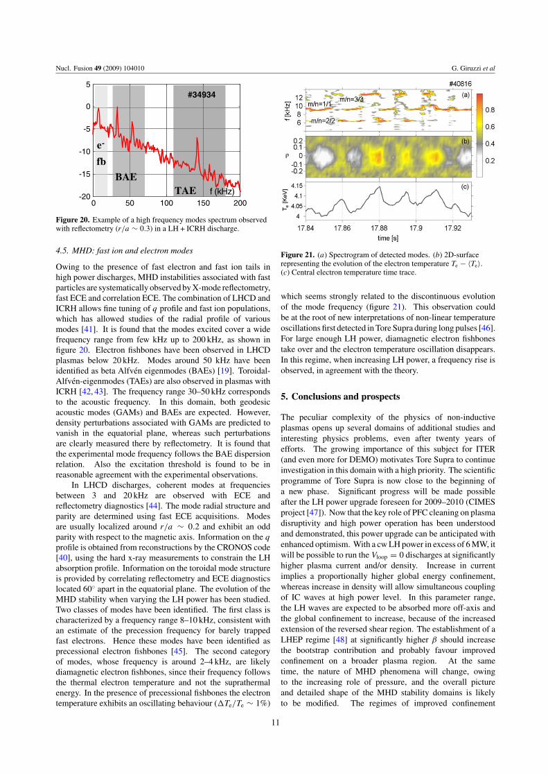
Figure 20. Example of a high frequency modes spectrum observedwith reflectometry (r/a ∼ 0.3) in a LH + ICRH discharge.
4.5. MHD: fast ion and electron modes
Owing to the presence of fast electron and fast ion tails inhigh power discharges, MHD instabilities associated with fastparticles are systematically observed by X-mode reflectometry,fast ECE and correlation ECE. The combination of LHCD andICRH allows fine tuning of q profile and fast ion populations,which has allowed studies of the radial profile of variousmodes [41]. It is found that the modes excited cover a widefrequency range from few kHz up to 200 kHz, as shown infigure 20. Electron fishbones have been observed in LHCDplasmas below 20 kHz. Modes around 50 kHz have beenidentified as beta Alfven eigenmodes (BAEs) [19]. Toroidal-Alfven-eigenmodes (TAEs) are also observed in plasmas withICRH [42, 43]. The frequency range 30–50 kHz correspondsto the acoustic frequency. In this domain, both geodesicacoustic modes (GAMs) and BAEs are expected. However,density perturbations associated with GAMs are predicted tovanish in the equatorial plane, whereas such perturbationsare clearly measured there by reflectometry. It is found thatthe experimental mode frequency follows the BAE dispersionrelation. Also the excitation threshold is found to be inreasonable agreement with the experimental observations.
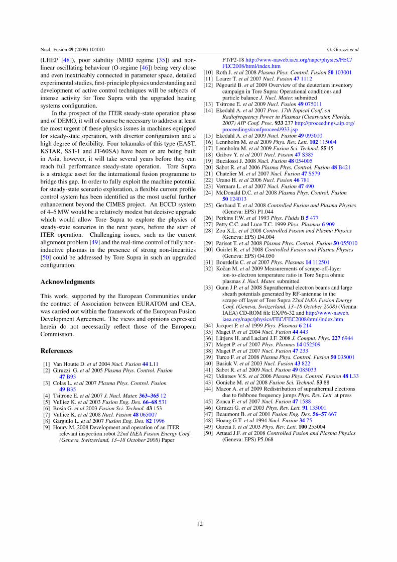
In LHCD discharges, coherent modes at frequenciesbetween 3 and 20 kHz are observed with ECE andreflectometry diagnostics [44]. The mode radial structure andparity are determined using fast ECE acquisitions. Modesare usually localized around r/a ∼ 0.2 and exhibit an oddparity with respect to the magnetic axis. Information on the q
profile is obtained from reconstructions by the CRONOS code[40], using the hard x-ray measurements to constrain the LHabsorption profile. Information on the toroidal mode structureis provided by correlating reflectometry and ECE diagnosticslocated 60◦ apart in the equatorial plane. The evolution of theMHD stability when varying the LH power has been studied.Two classes of modes have been identified. The first class ischaracterized by a frequency range 8–10 kHz, consistent withan estimate of the precession frequency for barely trappedfast electrons. Hence these modes have been identified asprecessional electron fishbones [45]. The second categoryof modes, whose frequency is around 2–4 kHz, are likelydiamagnetic electron fishbones, since their frequency followsthe thermal electron temperature and not the suprathermalenergy. In the presence of precessional fishbones the electrontemperature exhibits an oscillating behaviour (�Te/Te ∼ 1%)
Figure 21. (a) Spectrogram of detected modes. (b) 2D-surfacerepresenting the evolution of the electron temperature Te − 〈Te〉.(c) Central electron temperature time trace.
which seems strongly related to the discontinuous evolutionof the mode frequency (figure 21). This observation couldbe at the root of new interpretations of non-linear temperatureoscillations first detected in Tore Supra during long pulses [46].For large enough LH power, diamagnetic electron fishbonestake over and the electron temperature oscillation disappears.In this regime, when increasing LH power, a frequency rise isobserved, in agreement with the theory.
5. Conclusions and prospects
The peculiar complexity of the physics of non-inductiveplasmas opens up several domains of additional studies andinteresting physics problems, even after twenty years ofefforts. The growing importance of this subject for ITER(and even more for DEMO) motivates Tore Supra to continueinvestigation in this domain with a high priority. The scientificprogramme of Tore Supra is now close to the beginning ofa new phase. Significant progress will be made possibleafter the LH power upgrade foreseen for 2009–2010 (CIMESproject [47]). Now that the key role of PFC cleaning on plasmadisruptivity and high power operation has been understoodand demonstrated, this power upgrade can be anticipated withenhanced optimism. With a cw LH power in excess of 6 MW, itwill be possible to run the Vloop = 0 discharges at significantlyhigher plasma current and/or density. Increase in currentimplies a proportionally higher global energy confinement,whereas increase in density will allow simultaneous couplingof IC waves at high power level. In this parameter range,the LH waves are expected to be absorbed more off-axis andthe global confinement to increase, because of the increasedextension of the reversed shear region. The establishment of aLHEP regime [48] at significantly higher β should increasethe bootstrap contribution and probably favour improvedconfinement on a broader plasma region. At the sametime, the nature of MHD phenomena will change, owingto the increasing role of pressure, and the overall pictureand detailed shape of the MHD stability domains is likelyto be modified. The regimes of improved confinement
11
Nucl. Fusion 49 (2009) 104010 G. Giruzzi et al
(LHEP [48]), poor stability (MHD regime [35]) and non-linear oscillating behaviour (O-regime [46]) being very closeand even inextricably connected in parameter space, detailedexperimental studies, first-principle physics understanding anddevelopment of active control techniques will be subjects ofintense activity for Tore Supra with the upgraded heatingsystems configuration.
In the prospect of the ITER steady-state operation phaseand of DEMO, it will of course be necessary to address at leastthe most urgent of these physics issues in machines equippedfor steady-state operation, with divertor configuration and ahigh degree of flexibility. Four tokamaks of this type (EAST,KSTAR, SST-1 and JT-60SA) have been or are being builtin Asia, however, it will take several years before they canreach full performance steady-state operation. Tore Suprais a strategic asset for the international fusion programme tobridge this gap. In order to fully exploit the machine potentialfor steady-state scenario exploration, a flexible current profilecontrol system has been identified as the most useful furtherenhancement beyond the CIMES project. An ECCD systemof 4–5 MW would be a relatively modest but decisive upgradewhich would allow Tore Supra to explore the physics ofsteady-state scenarios in the next years, before the start ofITER operation. Challenging issues, such as the currentalignment problem [49] and the real-time control of fully non-inductive plasmas in the presence of strong non-linearities[50] could be addressed by Tore Supra in such an upgradedconfiguration.
Acknowledgments
This work, supported by the European Communities underthe contract of Association between EURATOM and CEA,was carried out within the framework of the European FusionDevelopment Agreement. The views and opinions expressedherein do not necessarily reflect those of the EuropeanCommission.
References
[1] Van Houtte D. et al 2004 Nucl. Fusion 44 L11[2] Giruzzi G. et al 2005 Plasma Phys. Control. Fusion
47 B93[3] Colas L. et al 2007 Plasma Phys. Control. Fusion
49 B35[4] Tsitrone E. et al 2007 J. Nucl. Mater. 363–365 12[5] Vulliez K. et al 2003 Fusion Eng. Des. 66–68 531[6] Bosia G. et al 2003 Fusion Sci. Technol. 43 153[7] Vulliez K. et al 2008 Nucl. Fusion 48 065007[8] Gargiulo L. et al 2007 Fusion Eng. Des. 82 1996[9] Houry M. 2008 Development and operation of an ITER
relevant inspection robot 22nd IAEA Fusion Energy Conf.(Geneva, Switzerland, 13–18 October 2008) Paper
FT/P2-18 http://www-naweb.iaea.org/napc/physics/FEC/FEC2008/html/index.htm
[10] Roth J. et al 2008 Plasma Phys. Control. Fusion 50 103001[11] Loarer T. et al 2007 Nucl. Fusion 47 1112[12] Pegourie B. et al 2009 Overview of the deuterium inventory
campaign in Tore Supra: Operational conditions andparticle balance J. Nucl. Mater. submitted
[13] Tsitrone E. et al 2009 Nucl. Fusion 49 075011[14] Ekedahl A. et al 2007 Proc. 17th Topical Conf. on
Radiofrequency Power in Plasmas (Clearwater, Florida,2007) AIP Conf. Proc. 933 237 http://proceedings.aip.org/proceedings/confproceed/933.jsp
[15] Ekedahl A. et al 2009 Nucl. Fusion 49 095010[16] Lennholm M. et al 2009 Phys. Rev. Lett. 102 115004[17] Lennholm M. et al 2009 Fusion Sci. Technol. 55 45[18] Gribov Y. et al 2007 Nucl. Fusion 47 S385[19] Bucalossi J. 2008 Nucl. Fusion 48 054005[20] Sabot R. et al 2006 Plasma Phys. Control. Fusion 48 B421[21] Chatelier M. et al 2007 Nucl. Fusion 47 S579[22] Urano H. et al 2006 Nucl. Fusion 46 781[23] Vermare L. et al 2007 Nucl. Fusion 47 490[24] McDonald D.C. et al 2008 Plasma Phys. Control. Fusion
50 124013[25] Gerbaud T. et al 2008 Controlled Fusion and Plasma Physics
(Geneva: EPS) P1.044[26] Perkins F.W. et al 1993 Phys. Fluids B 5 477[27] Petty C.C. and Luce T.C. 1999 Phys. Plasmas 6 909[28] Zou X.L. et al 2008 Controlled Fusion and Plasma Physics
(Geneva: EPS) D4.004[29] Parisot T. et al 2008 Plasma Phys. Control. Fusion 50 055010[30] Guirlet R. et al 2008 Controlled Fusion and Plasma Physics
(Geneva: EPS) O4.050[31] Bourdelle C. et al 2007 Phys. Plasmas 14 112501[32] Kocan M. et al 2009 Measurements of scrape-off-layer
ion-to-electron temperature ratio in Tore Supra ohmicplasmas J. Nucl. Mater. submitted
[33] Gunn J.P. et al 2008 Suprathermal electron beams and largesheath potentials generated by RF-antennae in thescrape-off layer of Tore Supra 22nd IAEA Fusion EnergyConf. (Geneva, Switzerland, 13–18 October 2008) (Vienna:IAEA) CD-ROM file EX/P6-32 and http://www-naweb.iaea.org/napc/physics/FEC/FEC2008/html/index.htm
[34] Jacquet P. et al 1999 Phys. Plasmas 6 214[35] Maget P. et al 2004 Nucl. Fusion 44 443[36] Lutjens H. and Luciani J.F. 2008 J. Comput. Phys. 227 6944[37] Maget P. et al 2007 Phys. Plasmas 14 052509[38] Maget P. et al 2007 Nucl. Fusion 47 233[39] Turco F. et al 2008 Plasma Phys. Control. Fusion 50 035001[40] Basiuk V. et al 2003 Nucl. Fusion 43 822[41] Sabot R. et al 2009 Nucl. Fusion 49 085033[42] Udintsev V.S. et al 2006 Plasma Phys. Control. Fusion 48 L33[43] Goniche M. et al 2008 Fusion Sci. Technol. 53 88[44] Macor A. et al 2009 Redistribution of suprathermal electrons
due to fishbone frequency jumps Phys. Rev. Lett. at press[45] Zonca F. et al 2007 Nucl. Fusion 47 1588[46] Giruzzi G. et al 2003 Phys. Rev. Lett. 91 135001[47] Beaumont B. et al 2001 Fusion Eng. Des. 56–57 667[48] Hoang G.T. et al 1994 Nucl. Fusion 34 75[49] Garcia J. et al 2003 Phys. Rev. Lett. 100 255004[50] Artaud J.F. et al 2008 Controlled Fusion and Plasma Physics
(Geneva: EPS) P5.068
12