Embed Size (px)
Citation preview
Investigation of Sustainable Machining Strategies for Difficult-to-Cut Materials
by
Abdelkrem Ali Aboulqasim Eltaggaz
A Thesis
presented to
The University of Guelph
In partial fulfilment of requirements
for the degree of
Doctor of Philosophy
in
Engineering
Guelph, Ontario, Canada
© Abdelkrem Ali Aboulqasim Eltaggaz, August, 2019
ii
ii
ABSTRACT
Investigation of Sustainable Machining Strategies for Difficult-to-Cut Materials
Abdelkrem Eltaggaz Advisor:
University of Guelph, 2019 Professor I. Deiab Co-Advisor:
Professor H. Kishawy
Over the past few decades, the demand for employing sustainable machining has increased because of high
competition, and operator health, and environmental concerns. The generated heat is an immense challenge
when machining difficult-to-cut materials such as Austempered Ductile Iron (ADI) and Ti-6Al-4V alloy due
to their poor thermal conductivity. The amount of heat generated significantly affects their machinability.
Application sustainable cooling strategy instead of conventional flood for these materials has become more
desirable, so Minimum Quantity Lubrication (MQL) has been proposed. However, MQL has inefficient
cooling ability. To enhance the cooling and lubricating efficiency of an MQL, nanoparticles can be dispersed
into a base fluid, thereby creating an MQL-nanofluid.
This work attempts to improve the MQL machining performance by adding aluminum oxide (Al2O3)
nanoparticles which have superior tribological and thermal properties. Furthermore, to the best of the
author’s knowledge, there is a gap in the available literature regarding the numerical modelling of the ADI
machining process including the effect of coolant. ADI constitutive equation was coded into ABAQUS
software package and used for heat generation computations at the workpiece-tool interface. The results
were used in a Computational Fluid Dynamic (CFD) model to evaluate the heat removal ability of MQL in
the cutting zone. In this research, the Ti-6Al-4V alloy and ADI were machined at different cutting
iii
iii
parameters with different coolant approaches to optimize the combination of cutting parameters and
sustainable coolant methods. The findings showed that adding Al2O3 nanoparticles enhanced the
convection, wettability, and conduction characteristics of the proposed sustainable MQL-nanofluid
technique, and offered a significant improvement in tool wear behavior, power consumption, and surface
roughness in compared to regular MQL. The results of the CFD model for applying the MQL approach
during the machining of ADI were found to be in acceptable agreement with the experimental results.
This research determines an appropriate sustainable cooling technique to improve the machinability of ADI
and Ti-6Al-4V while considering both the operator's health and the environmental impacts. This work codes
the constitutive equation for ADI and develops both an effective FEM model and CFD simulation for the
machining of ADI using MQL cooling.

iv
iv
Acknowledgments
Thanks and gratitude is due to ALLAH for the continuous support I have felt throughout my life.
The author would like to thank all those who supported him during the course of this research.
Special thanks to my research supervisors Dr. Ibrahim M. Deiab and Dr. Hossam Kishawy for
their guidance and support throughout this study. Thanks to the member of the Supervisory
Committee, Dr. Marwan Hassan. Thanks to Zied Said for developing the project with regards to
the computational fluid dynamics model. Thanks are extended to Barry Verspagen, John Cloutier,
Ken Graham, Hong Ma, John Whiteside, David Wright, and Patricia Zawada for their assistance
in running the experimental tests, and the remainder of the Advanced Manufacturing Lab (AML)
team for their support.
In addition, I am deeply thankful to the Libyan Ministry of Higher Education and Scientific
Research, the Canadian Bureau for International Education (CBIE), and the Zawia Higher Institute
of Science and Technology for their financial scholarship. I would like also to thank the National
Science and Engineering Research Council of Canada (NSERC) and Ontario Centers of
Excellence (OCE) for their support funding this research. I would like to thank Wisam Al-Wajidi,
Dr. Hussien Hegab, and Nihad Alzuabidi for their friendship, their motivation and encouragement,
and their belief in me. Lastly but certainly not the least, I would like to acknowledge my wife and
my beautiful kids for their love and encouragement throughout the work on this research even
during the most trying of times.
v
v
TABLE OF CONTENTS
Abstract ...........................................................................................................................................ii
Acknowledgments……………………................................................................................iv
Table of Contents ………………………………………………………..………………….…..v
List of Tables …………..…………………………………………………………..……….......ix
List of Figures …………………………………………………………………………………...xi
Nomenclature …………………………………………………………………………………..xv
List of Appendices …………………………………………………………………………....xviii
Chapter 1: Introduction ………………………………………………………………..………..1
1.1 Preamble …………….……………………………………………………….…………1
1.2 Thesis Scope and Aim …….…….…………………………….…………………….…2
1.3 Thesis Objectives ……………...…………………………………………………….…3
1.4 Thesis Layout ………………………….…………………………………….………….5
Chapter 2: Literature Review …………………………………..……………….………….…..6
2.1 Introduction ………………….……………………………………………………….…6
2.2 Literature Review ……………….……………………...……….…………………….11
Chapter 3: Research Methodology.………………………………………….………..…......30
3.1 Introduction …………………………………..……………………….………...….…30
3.2 Design of Experiments (DOE) ……………..…………………….……………....…30
3.3 Planning of Experiments ………………..…………..…………………………..…...31
3.3.1 Cutting Tool and Workpiece materials ………………..…..…………….….32
3.3.1.1 Austempered Ductile Iron (ADI) …………………………..…….……33
3.3.1.2 Ti-6Al-4V Titanium Alloy ………..………………………....…….……34
3.3.1.3 Turning Cutting Tool Insert ………..….………………..………..……34
3.4 Experimental Setup ………………..…….…………………...……….……….……36
3.5 Measurement of Machining Variables ………..…………………………….….….39
vi
vi
3.5.1 Cutting Forces …………………………..………………………….…....…...39
3.5.2 Tool Wear and Wear Mechanisms ……………………….…….…..……....40
3.5.3 Machined Surface Roughness (Ra) ……………….………….……...….....43
3.5.4 Power Consumption ……………………….……….…………..……............44
3.6 Numerical Methodology …………………………………….…………….………….45
3.6.1 Design of Experiment …………………………...…………………….…..…..46
3.6.2 Experimental Setup ………………………………...……….…….……….….47
3.6.3 Thermocouple and Temperature Arrangement ……………….……………48
Chapter 4: Results and Discussion …………………………………….……………...……..52
4.1 The Effects of Using Different Coolant Strategies on Tool Life and
Surface Roughness …………………………….…………………………………....52
4.1.1 Introduction …………………………………….………………….………...…52
4.1.2 Results and Discussions ……………………………………….………….....54
4.1.2.1 Tool Life and Surface Roughness ………………...……………...........54
4.1.2.2 ANOVA Analysis ……………………………………….………...……...59
4.1.2.3 Response Surface Methodology (RSM) …….………..…….………....63
4.1.2.4 Wear Mechanisms Analysis ………….….………….……….………....69
4.1.3 Conclusion ……………………………………….…….……………...........…73
4.2 Hybrid Nanofluid-MQL Strategy for Machining ADI …….………………………...75
4.2.1 Introduction ……………………………………………….………….…………75
4.2.2 Results and Discussions ……………………………….……………………...76
4.2.2.1 Tool Wear ….………………………………………………………….….76
4.2.2.2 Nanoparticle Effects ……………………….…………….……………...79
4.2.2.3 Scanning Electron Microscope (SEM) Investigation ……………..…..81
4.2.2.4 Nanofluid-MQL Mechanism ………………………………....……….…84
4.2.3 Conclusion ………………………………………………………..…………….85
4.3 - Application of MQL with Nano-Fluids during Machining of Ti-6Al-4V Alloy:
vii
vii
Experimental Investigation and Analysis ………………………………………...87
4.3.1 Introduction …………………….……………………………….…….…...……87
4.3.2 Experimentations and Methodology...……………………….……………….90
4.3.3 Results and Discussion …………………………………….….……………....93
4.3.4 Tool Wear Mechanisms …….………………………….…………..……….…99
4.3.5 Nanofluid-MQL Mechanisms …….………………….……….…….…..……102
4.3.6 Conclusion …………………………………………….….….………………..103
Chapter 5: Sustainability Assessment of Machining Difficult-to-cut Materials ……….…105
5.1 Introduction …………………………………………………………..……………..105
5.2 Assessment Results …………………………..…………….…………………….108
5.3 Conclusion …………………………………………………………….……………110
Chapter 6: Modeling and Numerical Simulation …………………………………….……..112
6.1 Introduction ……………………………………………………………….………...112
6.2 Experimental Setup …………………………………………….………………….114
6.3 Finite Element Modeling ……………………….…………………….……………118
6.3.1 ADI Model for Orthogonal Turning Process …………………....….……….118
6.3.2 FEM Results ……………………..……………………………...………..…..121
6.4 CFD Modeling …………….…………………………………………….….………123
6.4.1 CFD Results …………………………………………...…………......……….123
6.4.1.1 Geometry for CFD Model ….………………………………….……….123
6.4.1.2 Meshing ………………….….…………………….………………….…124
6.4.1.3 Meshing Approach ………….……………………………………....…125
6.4.2 CFD Results under Dry and MQL Conditions ………….………..…....…...125
6.5 Conclusion ….…………….………….……….……………………….…………...130
Chapter 7: Conclusions and Future Work ………………………….……………………...131
7.1 Conclusions .………………………..…………………………………….……......133
7.2 Future work …………….……………………….…………………….…….……...133
viii
viii
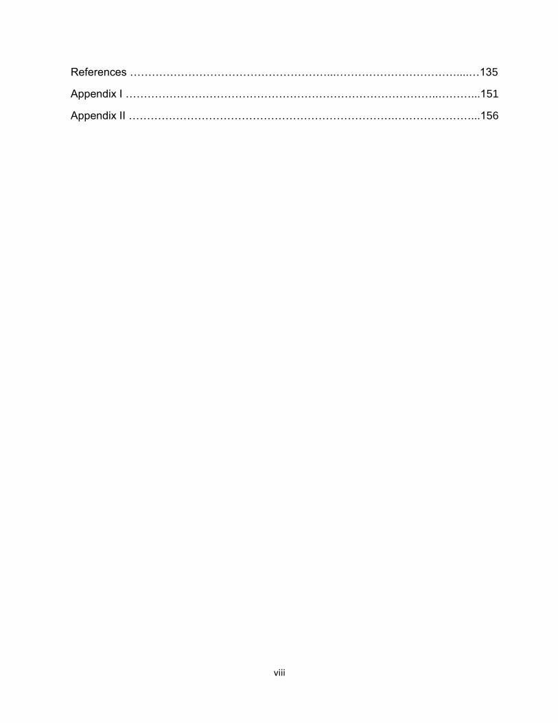
References ………………………………………………...……………………………....…135
Appendix I …………………………………………………………………………..………...151
Appendix II ……………………………………………………………….…………………...156
ix
LIST OF TABLES
Table 2.1: Summary of available research on MQL and MQCL coolants ……………..…..27
Table 2.2: (a) Summary of available research on nanofluid coolants ……………………….28
Table 2.2: (b) Summary of available research on nanofluid coolants ………………………29
Table 3.1: Percent weight chemical compositions of ADI grade 2 (wt %) …………….…..33
Table 3.2: ASTM A897/897M-02 mechanical properties of ADI grade 2 ………….……….33
Table 3.3: Chemical compositions of Ti-6Al-4V (wt %) …………………………………...….34
Table 3.4: Ti-6Al-4V titanium alloy mechanical properties (at room temperature) …….…34
Table 3.5: Specifications of the base vegetable oil utilized in the MQL system ………..…39
Table 3.6: Specifications of the Kistler dynamometer …………………………………..…...40
Table 3.7: The Mitutoyo tool maker microscope information ………………………….….…41
Table 3.8: Specifications of the Mitutoyo surface roughness tester SJ 201P ………..……44
Table 3.9: PS 2500 power data logger specifications ………………………………….….…45
Table 3.10: Cutting tool (CCMT 12 04 04-KM) thermo-mechanical properties …………….46
Table 3.11: Specifications of Omega HH 374 data logger ………………………………..…49
Table 4.1: Assignment of levels to the cutting process variables …………………………...53
Table 4.2 L24OA experimental results ……………………………………………………......55
Table 4.3: ANOVA results for average surface roughness (Ra) …………………………….60
Table 4.4: ANOVA results for tool life ……………………………………….……………..…..62
Table 4.5: The coefficient of correlation results …………………………………………..…..65
x
x
Table 4.6: The studied parameter levels and the plan of the experiments …………….….77
Table 4.7: L9OA with respect to the studied design variables ……………..……………….93
Table 4.8: The machining parameter levels and the output measurements ………………94
Table 4.9: Analysis of variance for maximum flank wear ………………………………..…..95
Table 4.10: Analysis of variance for surface roughness ………………………………..……96
Table 4.11: Analysis of variance for power consumption ………………………………..…..98
Table 5.1: Case 1: Equal weighting factors for all sustainable metrics and indicators…...106
Table 5.2: Case 2: Weighting factors for all sustainable metrics and indicators ……..…..107
Table 5.3: Case 3: Weighting factors for all sustainable metrics and indicators ……..…..107
Table 5.4: Case 4: Weighting factors for all sustainable metrics and indicators ….….…..108
Table 5.5: (a) Case (1): Sustainable factors and sustainable indexes ……………..……..109
Table 5.5: (b) Case (1): Weighted sustainable index ………………..……………….……..110
Table 5.6: Assessment algorithm outputs versus optimal machining experimental
outputs …………………………………………………………………………...….110
Table 6.1: Machining parameters and equipment specifications …………………….……115
Table 6.2: Thermo-mechanical properties of the ADI grade 2 …………………….……….118
Table 6.3: Thermo-mechanical properties of CCMT 12 04 04-KM (uncoated carbide)….118
Table 6.4: Parameters for the constitutive material law ……………………………...……..120
xi
xi
LIST OF FIGURES
Figure 1.1: Pillars of sustainable machining ……………………………………..………...…7
Figure 2.2: Financial costs and environmental impacts for using conventional cutting
fluid …………………………………………………………………………………..8
Figure 2.3: Applications of ADI in the marketplace …………………………..………..……9
Figure 2.4: Titanium components of an airplane jet engine (turbofan) ……………..……10
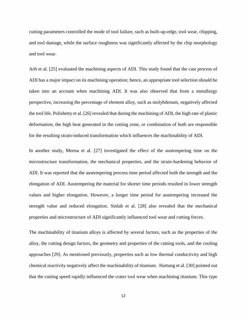
Figure 2.5: Heat generation during the machining process ………………..……………..15
Figure 3.1:CNMG120416MR (ISO) cutting tool insert ……………..………………………35
Figure 3.2: CNMT 12 04 08-KM H13A (ISO) cutting tool insert ……………………….…..35
Figure 3.3: CNC-lathe machine 15HP ST-10 HAAS ……………………………………….37
Figure 3.4: Experimental setup ……………………………………………………...……….38
Figure 3.5: Schematic experimental setup for machining ADI under different cooling
Strategies …………………………………………………………………………38
Figure 3.6: Cutting forces data evaluation system: (a) Kistler 9257b dynamometer,
and (b) Kistler 5070 charge amplifier …………………………………………40
Figure 3.7: (a) Tool maker microscope brand Mitutoyo (b) Standard measurement
of the maximum flank wear (VBmax) on the tool flank face …………...….….41
Figure 3.8: Scanning Electron Microscope (SEM) ………………………...……………….42
Figure 3.9: SEM images for a coated carbide tool (CNMG120416MR) after machining
ADI at V=120 m/min and f=0.3 mm/rev under dry machining ……...………...43
Figure 3.10: Mitutoyo surface roughness tester SJ 201P ……………………...…………..44
Figure 3.11: Power sight ………………………………………………..…………………….45
Figure 3.12: Experimental schematic ………………………………………………..……...47
xii
xii
Figure 3.13: Experimental setup (a), and temperature measuring arrangements (b),
(c) and (d) ………………………………………………………...……………...47
Figure 3.14: Experimental data acquisition flow diagram ………………………..………..49
Figure 3.15: Keyence VH-Z250R microscope ………………………..…………………….50
Figure 3.16: Thesis methodologies ………………………………………...………………..51
Figure 4.1: Experimental setup schematic …………………………………………...……..53
Figure 4.2: Cutting condition effects on tool life …………………………………………….56
Figure 4.3: Cutting condition effects on machined surface quality ………………...……..56
Figure 4.4: The interaction effect between the lubrication strategy and feed rate for
the average surface roughness results ………………………..……………....61
Figure 4.5: The interaction effect between the lubrication strategy and feed rate for the
tool life results …………………………………………………………………….63
Figure 4.6: ADI-dry cutting model for surface roughness results ……………………..….65
Figure 4.7: ADI-dry cutting model for tool life results ………………………..…………….66
Figure 4.8: ADI-flood cutting model for tool life results ………………………..………….66
Figure 4.9: ADI-flood cutting model for surface roughness results ……….……….………67
Figure 4.10: ADI-MQL cutting model for surface roughness results ………………….…..67
Figure 4.11: ADI-MQL cutting model for tool life results ………………………….….….…68
Figure 4.12: ADI-Nanofluid cutting model for tool life results ……………………….….…68
Figure 4.13: ADI-Nanofluid cutting model for surface roughness results ………..………68
Figure 4.14: EDS image for diffusion on the tool at dry machining f=0.2 mm/rev and
V=120 m/min ……………………...………………………..…………………....70
Figure 4.15: SEM images of inserts after machining at V=120 m/min and f=0.2 mm/rev
under different coolant strategies ………………………………………..…....71
Figure 4.16: SEM images of inserts after machining at V=120 m/min and f=0.3 mm/rev
xiii
xiii
under different coolant strategies …………………………………..………....73
Figure 4.17: Thermal conductivity results (Al2O3 nanofluid vs. vegetable oil) ………......76
Figure 4.18: Tool wear results ……………………………………………………………......78
Figure 4.19: Flank wear results at a feed rate of 0.2 mm/rev …………………….…….…79
Figure 4.20: Flank wear results at a feed rate of 0.3 mm/rev ………………………………79
Figure 4.21: The MQL-nanofluid mechanism schematic …………………………..……...80
Figure 4.22: Scanning Electron Microscope (SEM) images at a cutting speed of
180 m/min and a feed rate 0.2 mm/rev using MQL-Al2O3 nanofluid (a)
and classical MQL (b) …………………………………………..……………....82
Figure 4.23: The main tool wear modes when machining ADI at a cutting speed of
120 m/min and a feed rate of 0.3 mm/rev using (a) MQL-nanofluid, and
(b) pure MQL …………………………………………………………………..82
Figure 4.24: Images of (a) an AQUASONIC-50HT device used to achieve the
dispersion, and (b) a regular and a nanofluid-MQL …………………..……..91
Figure 4.25: The experimental schematic ………………………………...……………..…92
Figure 4.26: The main effects for the maximum flank wear (VB) ……………….………..95
Figure 4.27: Nanofluid-MQL mechanism schematic …………………………..…………..96
Figure 4.28: The main effects plot for surface roughness (Ra) ……………………...……97
Figure 4.29: The main effects plot for power consumption ……………………..…………98
Figure 4.30: Coefficient of friction and induced wear versus nanoparticle content...…….99
Figure 4.31: SEM and EDS pictures of the tool after using regular MQL ………………..100
Figure 4.32: SEM and EDS pictures of the tool after using MQL-Nanofluid 2 wt. % ……101
Figure 4.33: SEM and EDS pictures of the tool after using MQL-Nanofluid 4 wt. % ……101
Figure 4.34: The nanofluid-MQL mechanisms (a) rolling effect and (b)
ploughing effect ……………………………………………………………….103
xiv
xiv
Figure 6.1: Methodology schematic of the thermal behavior prediction for
machining ADI …………………...…………………………………...………...115
Figure 6.2: Experimental setup view (a); the installation and temperature measuring
arrangements (b), (c) & (d) ………………………………...…………………..117
Figure 6.3: Meshing and boundary conditions definition …………………………..……..121
Figure 6.4: (a) Finite element simulated cutting temperature (b) Temperature values
across the rake face (oC) …………………………………………..…………122
Figure 6.5: The heat flux contours ……………………………………………..…………...122
Figure 6.6: MQL versus other cooling methods in terms of heat transfer
Mechanisms .................................................................................................123
Figure 6.7: Geometry setup for the CFD analysis …………………………………… …..124
Figure 6.8: Meshing setup for the CFD analysis ………………………………...………...125
Figure 6.9: Velocity contours (a), and heat transfer coefficient distribution (b) …………126
Figure 6.10: ANSYS Fluent/ANSYS transient thermal coupled link …………..…………127
Figure 6.11: Comparison between the experimental and the simulation temperatures
under dry machining conditions …………………………..…………………128
Figure 6.12: Comparison between the experimental and simulation temperatures
under MQL conditions ……………………………………..…………………129
xv
xv
NOMENCLATURES
ADI Austempered ductile iron
Al2O3 Aluminum oxide nanoparticles
ALE Arbitrary Lagranian Eulerian
ANOVA Analysis of variance
BUL Built-up-edge layer
CAMQL Chilled air minimum quantity lubrication
CFD Computational fluid dynamic
CNC Computer numerical control
CNTs Carbon nanotubes
CO2 Carbon dioxide
c Material specific heat
DOE Design of experiments
DPM Discrete phase model
EDS Energy dispersive X-ray spectroscopy
EHS Environmental health and safety
EPA Environmental protection agency
f Feed rate
FEA Finite element analysis
FEM Finite element model
HSS High speed steel
KN Kilo newton
Kp Thermal conductivity of nanoparticle
Kf Thermal conductivity of base fluid
Km Thermal conductivity of resultant
GPa Gage Pascal
J Joule
L24OA 24 orthogonal array
L9OA 9 orthogonal array
MPa Mage Pascal
xvi
xvi
MQL Minimum quantity lubrication
MQCL Minimum quantity cooling lubrication
MWCNT Multi walled carbon nanotubes
MWF Metalworking fluid
NDM Near-dry machining
NFMQL Nanofluid minimum quantity lubrication
NIOSH National institute for occupational safety and health
OSI Overall sustainable index
OStc Operator personal health, express the toxic effect
OShtc Operator personal health, high temperature surface exposure
Pn Operator personal health, noise effect
PVD Physical vapor deposition
RSM Response surface methodology
Ra Surface roughness
SDS Sodium dodecyl sulfate
SEM Scanning electron microscope
T Temperature
TRIP Transformation induced plasticity
SI Sustainable index
SiC Nano-silicon carbide
v Cutting speed
Vf Nanoparticles volume fraction
VB Maximum flank tool wear
Wt. % Weight percentage
WSI Weighted sustainable index
ρ Material density
η Inelastic heat fraction
σ Flow stress
εpl Plastic strain
ε Strain rate
ε Strain
xvii
xvii
γ Rake angle
θ Clearance angle
m Frictional coefficient
T Temperature rate
χ Ductile softening term
K1 Material constant
K Material constant
εG Limit strain
εG Limit strain rate
T0 Base temperature
Tm Melting temperature
n Hardening exponent
β Material constant of the temperature function
ψ(T) Thermal softening term
γ Rake angle
θ Clearance angle

xviii
xviii
LIST OF APPENDICES
Appendix I ………………………………………………………………………………...144
Appendix II ………………………………………………………………………………..149
1
Chapter 1: Introduction
1.1 Preamble
In metal cutting, the cutting fluid and design machining parameters impact the machining outputs
such as cutting forces, surface quality, cutting temperature, and friction coefficient. During
machining, heat is generated in three cutting regions: the primary shear region, the secondary
deformation region, and the tertiary region (tool flank-workpiece contact). Approximately 2/3 to
3/4 of the heat is generated by friction force as the chips slide along the cutting tool face, and
through the plastic deformation of the metal. The heat that is generated becomes a more significant
issue when machining difficult-to-cut materials such as Ti-6Al-4V titanium alloy and austempered
ductile iron (ADI). Cooling and lubrication during the machining process can be provided by
cutting fluids. Using a cutting fluid decreases the tool wear and extends the tool life. In the
manufacturing industry, the use of conventional flood coolant is a common cooling strategy.
However, due to its relatively high cost and the negative implications to the operator`s health and
the environment, sustainable cooling approaches have become more desirable. One of these
approaches is Minimum Quantity Lubrication (MQL), which has been determined to be an
effective near dry machining method. Its cooling capacity, however, is relatively low compared to
a conventional flood coolant. This study aims to improve the MQL thermal performance in the
cutting zone with respect to cutting forces, power consumption, tool life, and surface roughness
during the turning of T1-6Al-4V alloy and austempered ductile iron (ADI).
To the best of the author's knowledge there is a gap in the available literature regarding FE models
of ADI Machining due to the unavailability of its constitutive equation.
2
2
1.2 Thesis Scope
The application of sustainable cooling strategies in metal cutting processes has always been of
attentiveness. In metal cutting, the cutting fluids consumption and the power (energy) requirements
are linked to the environmental effects of the cutting practice. Difficult-to-cut materials such as
austempered ductile iron (ADI) and Ti-6Al-4V titanium alloy are preferred over other metals such
as aluminium and steel alloys. This is due to their unique properties, which include a high strength
to weight ratio, fatigue resistance, and excellent corrosion resistance. ADI has become widely used
in the automotive industry, and titanium alloys are used in biomedical and aerospace
implementations due to their resistance to crack growth, resilience to creep, and fatigue behaviour.
Second chapter presents a literature review of the study performed on the sustainability features of
the machining of ADI and Ti-6Al-4V alloy with a focus on investigating the near dry and the
environmental friendly cooling approach. The literature showed that research has focused on the
coolant approaches, namely flood cooling, cryogenic, minimum quantity lubrication (MQL),
minimum quantity cooling lubrication (MQCL), and nanofluid-MQL. The literature also presented
a research gap in that the constitutive equation for ADI is not available by default because of its
contradictory nature. That is why there have been no studies in which an FE model of machining
simulations has been performed for ADI. Also, insufficient research has been attempted to
incorporate finite element models (FEM) and computational fluid dynamic (CFD) modelling in
cutting operations to investigate the interactions of MQL technique during the machining of ADI.
This research envisages covering the gap in the available literature on the use of nanofluid-MQL
as a potential environmentally sustainable cooling approach for machining difficult-to-cut
materials, such as ADI and Ti-6Al-4V titanium alloy. In manufacturing processes, efficient
machining can significantly decrease the costs and the environmental impacts of the product. The
3
3
current study also intends to address the potential applications of FEM and CFD simulations to
facilitate the use of a sustainable cooling approach (MQL) in the cutting of ADI.
1.3 Thesis Objectives
Cooling strategies have a controlling effect on the performance of the cutting process. There has
been limited research on how to enhance the efficiency of coolant strategies and optimize the
parameters. To that end, an experimental study and a numerical model of new coolant strategies
when machining difficult-to-cut materials would increase the potential for more economic,
efficient and environmental machining processes. This research thesis has the following aims:
1. The terms “environmental" and "sustainability” are liberally used to refer to efficient power
consumption, the use of a minimal volume of coolant (litre/min in flood to mill-litre/hr in
MQL), and the use of vegetable oils. MQLs have a niche of applications that would prove
to be beneficial both economically and environmentally. However, the open literature still
requires more research and experimental data on the effects of using different cooling
approaches on the process performance during the machining of difficult-to-cut materials.
In particular, MQL and MQL-nanofluid hybrid strategies must be addressed, which is one
of the objectives of this thesis.
2. This work assesses the performance of an MQL combined with nanofluids, i.e. a nanofluid-
MQL. The MQL method has an inefficient cooling capacity compared to standard flood
coolant, particularly when machining difficult-to-cut materials such as ADI and Ti-6Al-4V
alloy. Therefore, numerous researchers have attempted to improve the MQL’s cooling
capacity. In this work, nanoparticles (Al2O3) are added to the MQL base oil fluid in order
to enhance its cooling and lubricating properties.
4
4
3. Wear progression and mechanisms when machining difficult-to-cut materials (e.g. ADI
grade 2 and Ti-6Al-4V titanium alloy) are identified. Understanding the tribological
behaviour and characteristics of the MQL media and nano-additives during the machining
of difficult-to-cut materials is crucial to optimizing the process, and needs further
investigation.
4. Numerical models are being developed to better simulate the machining environment. One
of the biggest challenges in the metal cutting process is to predict the cutting temperature
either experimentally or numerically. High temperature in the cutting zone has a
controlling impact on tool wear and the resulting surface integrity of the machined surface.
Many researchers have investigated different experimental and numerical approaches to
accurately predict the cutting temperature. An accurate prediction of the cutting
temperature is one of the greatest factors that control the accuracy of the predicted cutting
forces and tool wear. Developing a model that accounts for both the thermal and the
mechanical sides of the ADI machining process has yet to be realized. To the best of the
researcher’s knowledge, the available literature has rarely addressed the simulation of heat
transfer analysis in the cutting zone for cutting ADI grade 2. However, this thesis develops
a model that utilizes both finite elements (FEA) and computational fluid dynamics (CFD)
to simulate the influence of an MQL cooling media on the machining environment of ADI
grade 2. The results of this work were promising, and prove that this concept is possible.
The work sheds some light onto the challenges that face such a model. This work is the
foundation upon which an accurate prediction of the temperature distribution in the cutting
zone will be achieved, as it is one of the objectives of the modelling component of this
research thesis.

5
5
1.4 Thesis Layout
The research study is divided into six chapters and follows a sandwich style, in which Chapter 4
represents the published articles. The thesis outline is as follows:
Chapter 1 introduces the scope and objectives of the thesis, and outlines the overall structure of
this research.
Chapter 2 reviews the existing state of difficult-to-cut materials in the manufacturing industry,
the sustainable coolant strategies used, and the gaps in the available research on the expanding use
of alternative coolant strategies. This leads into a discussion of how minimum quantity lubrication
performs under different machining criteria. The review continues by discussing the issues of
MQL, with alternative options to improve its performance by adding nanoparticles.
Chapter 3 details the experimental setup adapted to conduct the intended study. The machining
experiments are conducted on Austempered Ductile Iron (ADI) grade 2 and Ti-6Al-4V titanium
alloy.
Chapter 4 represents and discusses the findings and conclusions obtained from the published
papers.
Chapter 5 presents the assessment study for machining Ti-6Al-4V alloy.
Chapter 6 discusses the numerical outputs obtained from the finite element model (FEM) and the
computational fluid dynamics model (CFD), as well as the experimental temperature.
Chapter 7 provides the conclusions and the recommended future work to further improve the
practicality and performance of the CFD mode
6
6
Chapter 2: Literature Review
2. 1 Introduction
For decades, machining processes have been playing a crucial role in the global economy.
However, due to a combination of high competition in the industrial marketplace and
environmental concerns, manufacturing industries have recently been focusing on minimizing
machining costs, increasing the quality of the product, and reducing their ecological footprint.
Sustainable manufacturing is a novel technique for producing product in an efficient manner.
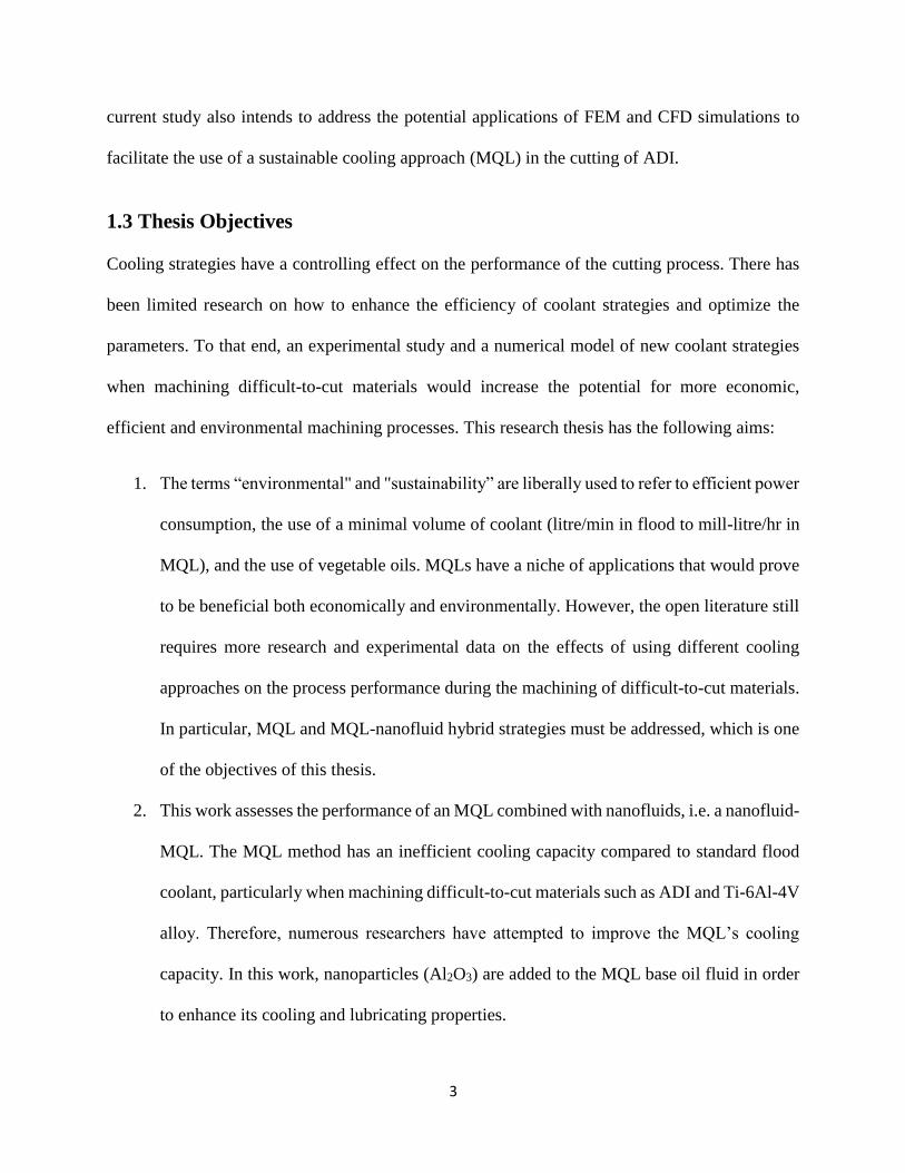
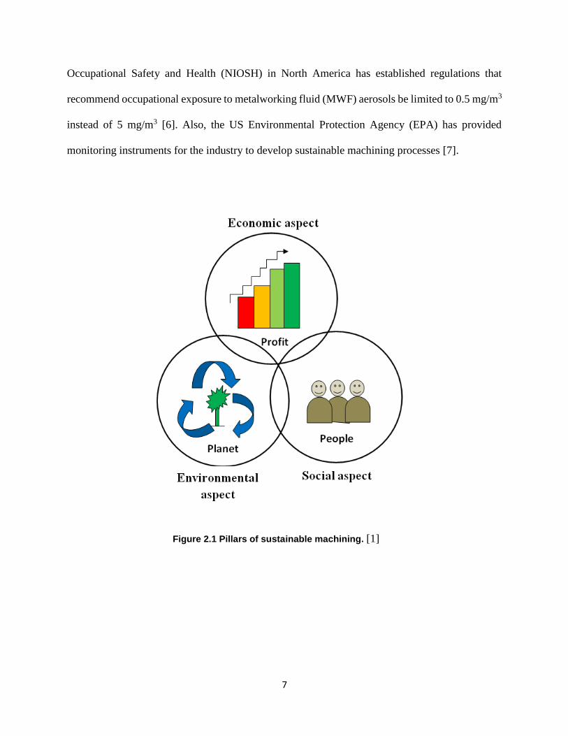
Sustainability has many descriptions and various pillars. Figure 2.1 presents the three major pillars
of sustainable manufacturing: economy, society, and environment [1]. In metal removal processes,
the dry condition is considered to be environmentally friendly machining because no cutting fluid
is used. However, dry machining often results in problems by cause of the high amount of heat in
the cutting zone, especially for difficult-to-cut materials.
In order to improve tool life and machined surface quality during the machining process, cutting
fluids are utilized extensively to reduce the heat generated at the cutting zone [2]. However, the
excessive use of conventional cutting fluids in flood cooling and aerosols has been found to be the
source of greenhouse gas, which negatively affects the operator’s health and environs [3]. Disposal
of coolants contaminates the environment because these substances contain machined particles
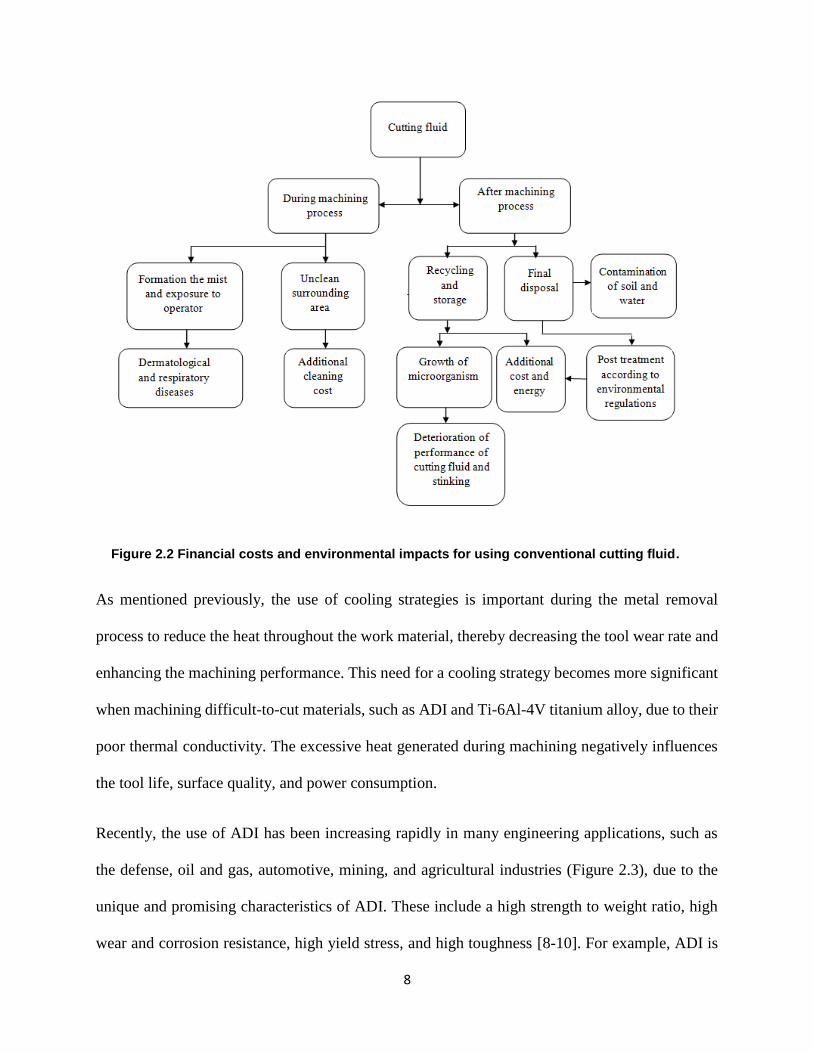
and hazardous chemicals [4]. Coolant disposal, supply, storage, and maintenance processes
increase the total production costs (Figure 2.2) [5]. Thus, concerns about environmental issues,
unfavourable impacts on the operators’ health, and increased total production costs, have
highlighted the importance of decreasing or eliminating the cutting fluids application. Some
government regulations have been established; for example, the National Institute for
7
7
Occupational Safety and Health (NIOSH) in North America has established regulations that
recommend occupational exposure to metalworking fluid (MWF) aerosols be limited to 0.5 mg/m3
instead of 5 mg/m3 [6]. Also, the US Environmental Protection Agency (EPA) has provided
monitoring instruments for the industry to develop sustainable machining processes [7].
Figure 2.1 Pillars of sustainable machining. [1]
8
8
Figure 2.2 Financial costs and environmental impacts for using conventional cutting fluid.
As mentioned previously, the use of cooling strategies is important during the metal removal
process to reduce the heat throughout the work material, thereby decreasing the tool wear rate and
enhancing the machining performance. This need for a cooling strategy becomes more significant
when machining difficult-to-cut materials, such as ADI and Ti-6Al-4V titanium alloy, due to their
poor thermal conductivity. The excessive heat generated during machining negatively influences
the tool life, surface quality, and power consumption.
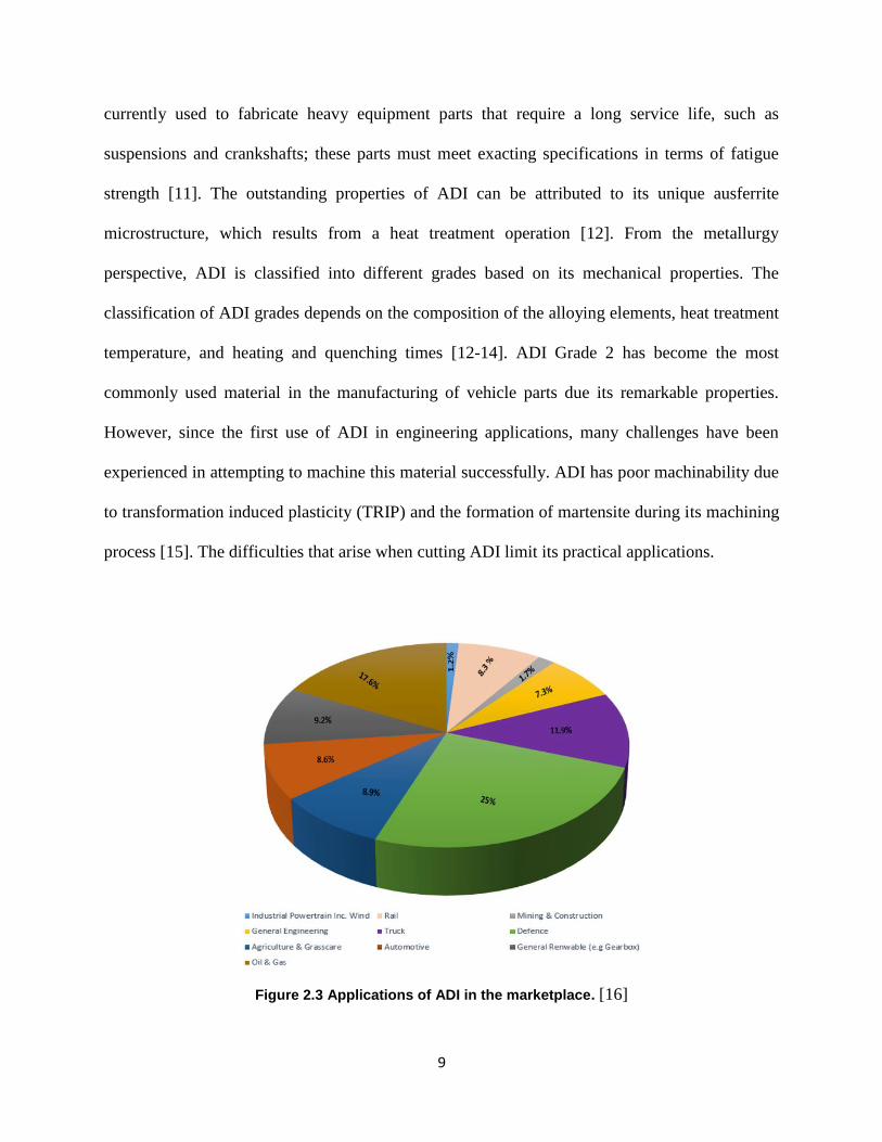
Recently, the use of ADI has been increasing rapidly in many engineering applications, such as
the defense, oil and gas, automotive, mining, and agricultural industries (Figure 2.3), due to the
unique and promising characteristics of ADI. These include a high strength to weight ratio, high
wear and corrosion resistance, high yield stress, and high toughness [8-10]. For example, ADI is
9
9
currently used to fabricate heavy equipment parts that require a long service life, such as
suspensions and crankshafts; these parts must meet exacting specifications in terms of fatigue
strength [11]. The outstanding properties of ADI can be attributed to its unique ausferrite
microstructure, which results from a heat treatment operation [12]. From the metallurgy
perspective, ADI is classified into different grades based on its mechanical properties. The
classification of ADI grades depends on the composition of the alloying elements, heat treatment
temperature, and heating and quenching times [12-14]. ADI Grade 2 has become the most
commonly used material in the manufacturing of vehicle parts due its remarkable properties.
However, since the first use of ADI in engineering applications, many challenges have been
experienced in attempting to machine this material successfully. ADI has poor machinability due
to transformation induced plasticity (TRIP) and the formation of martensite during its machining
process [15]. The difficulties that arise when cutting ADI limit its practical applications.
Figure 2.3 Applications of ADI in the marketplace. [16]
10
10
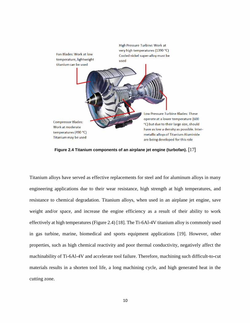
Figure 2.4 Titanium components of an airplane jet engine (turbofan). [17]
Titanium alloys have served as effective replacements for steel and for aluminum alloys in many
engineering applications due to their wear resistance, high strength at high temperatures, and
resistance to chemical degradation. Titanium alloys, when used in an airplane jet engine, save
weight and/or space, and increase the engine efficiency as a result of their ability to work
effectively at high temperatures (Figure 2.4) [18]. The Ti-6Al-4V titanium alloy is commonly used
in gas turbine, marine, biomedical and sports equipment applications [19]. However, other
properties, such as high chemical reactivity and poor thermal conductivity, negatively affect the
machinability of Ti-6Al-4V and accelerate tool failure. Therefore, machining such difficult-to-cut
materials results in a shorten tool life, a long machining cycle, and high generated heat in the
cutting zone.
11
11
2.2 Literature Review
Machining of difficult-to-cut materials is difficult, and the appearance of severe adhesive and
abrasive wear on a tool's cutting edge during the machining process shortens the tool's life. As a
result, research has investigated the factors that influence the machinability of ADI and titanium
alloys. Akdemir et al. [20] investigated the effect of depth of cut and cutting speed on the
machinability of ADI. The study evaluated ADI machinability by measuring surface roughness,
cutting forces, and flank wear. Experimental data and a response surface methodology (RSM)
technique were utilized to expose the influence of machining factors on ADI machinability. The
investigation found that the depth of cut has an insignificant influence on cutting forces. The study
also indicated that the cutting speed was a significant parameter that affected tool life (flank wear),
tangential cutting force, and surface roughness.
Parhad et al. [21] investigated the impact of depth of cut on ADI machinability in terms of
machined surface quality. It was observed that increasing the cutting speed improved the machined
surface quality. The surface roughness increased as the cutting speed decreased. This study also
concluded that the best machined surface quality was obtained when ADI was turned at a speed
between 150-200 m/min, a feed rate of 0.1 mm/rev, and a depth of cut of 2 mm.
Hegde et al. [22] investigated the influences of heat treatment and cutting parameters on a
manganese ADI alloy under dry condition. It was found that the cutting speed and austempering
temperature have the greatest effects on tool wear, whereas the feed rate has the most significant
effect on the surface roughness. Meena et al. [23] also drilled ADI under dry machining to study
the influence of cutting parameters on tool wear, cutting forces, chip morphology, and machined
surface integrity. The findings showed that a combination of a higher speed and a lower feed rate
resulted in higher cutting forces. Polishetty [24] also found that during the machining of ADI,
12
12
cutting parameters controlled the mode of tool failure, such as built-up-edge, tool wear, chipping,
and tool damage, while the surface roughness was significantly affected by the chip morphology
and tool wear.
Arft et al. [25] evaluated the machining aspects of ADI. This study found that the cast process of
ADI has a major impact on its machining operation; hence, an appropriate tool selection should be
taken into an account when machining ADI. It was also observed that from a metallurgy
perspective, increasing the percentage of element alloy, such as molybdenum, negatively affected
the tool life. Polishetty et al. [26] revealed that during the machining of ADI, the high rate of plastic
deformation, the high heat generated in the cutting zone, or combination of both are responsible
for the resulting strain-induced transformation which influences the machinability of ADI.
In another study, Meena et al. [27] investigated the effect of the austempering time on the
microstructure transformation, the mechanical properties, and the strain-hardening behavior of
ADI. It was reported that the austempering process time period affected both the strength and the
elongation of ADI. Austempering the material for shorter time periods resulted in lower strength
values and higher elongation. However, a longer time period for austempering increased the
strength value and reduced elongation. Sinlah et al. [28] also revealed that the mechanical
properties and microstructure of ADI significantly influenced tool wear and cutting forces.
The machinability of titanium alloys is affected by several factors, such as the properties of the
alloy, the cutting design factors, the geometry and properties of the cutting tools, and the cooling
approaches [29]. As mentioned previously, properties such as low thermal conductivity and high
chemical reactivity negatively affect the machinability of titanium. Hartung et al. [30] pointed out
that the cutting speed rapidly influenced the crater tool wear when machining titanium. This type
13
13
of tool wear was due to both the low thermal conductivity of titanium and the chemical reaction
between the titanium and the cutting tool material. Maekawa et al. [31] also found that crater wear
increased with an increase in cutting speed because the increased speed resulted in a higher cutting
temperature.
Tugrul et al. [32] reported that a better tool life was obtained when machining titanium by
combining a lower speed and a lower feed rate. Ramana et al. [33] also reported that the cutting
speed had a major effect on the reduction in the tool wear rate, while the feed rate had a major
effect on the surface roughness. This idea was supported by Ojolo et al. [34] when machining
titanium under dry machining using three different cutting tools (HSS, tungsten carbide, and
DNMG carbide) to examine the effect of cutting parameters on tool life. This study revealed that
the tool life was most affected by the cutting speed, followed by the feed rate, and the depth of cut.
The authors concluded that machining titanium at a low cutting speed with a suitable feed rate
should extend tool life.
Narutaki et al. [35] provided experimental results which indicated that coated carbide tools showed
a better surface roughness when compared to other cutting tools when machining a titanium alloy.
That was supported by Liu et al. [36] when machining a Ti-6Al-4V titanium alloy at different
cutting parameters using MQL vegetable oil. The analysis indicated that the feed rate was the main
factor influencing cutting forces and surface roughness. These studies concluded that cutting speed
significantly affects the wear rate and tool life, while surface roughness is mainly influenced by
the feed rate.
Narasimhulu et al. [37] machined titanium Ti-6Al-4V with a PVD coated tool at various cutting
parameters using dry machining. This study also found that the feed rate and the cutting speed
14
14
were the most significant factors that can influence the surface roughness. Ying-lin et al. [38]
reported that when machining titanium, the elevated heat in the cutting zone can lower the quality
of the finished surface due to chips melting and adhering to both the tool face and the machined
surface.
The dissipation of the generated heat from the cutting zone is limited in ADI and Ti-6Al-4V
titanium alloy due to the low thermal conductivity of these materials, resulting in poor
machinability. The heat is generated by the plastic deformation (primary zone), sliding chips effect
(secondary zone), and the friction between the tool surface and workpiece surface (tertiary zone)
as shown in Figure 2.5) [39, 40]. Optimizing the cutting parameters is difficult when machining
ADI and Ti-6Al-4V titanium alloy since the heat generated in the cutting zone is not efficiently
reduced by removing the chips, as is the case when machining other materials [41]. Instead, the
heat settles in the tool tip, thereby accelerate the cutting tool failure. The high temperatures of the
cutting tool, and the heat generated in the primary shear zone at the tool–chip interface, make the
machinability of these materials challenging. Shaw et al. [42] reported that during the machining
process, the majority of the supplied energy (approximately 80%) was used for material
deformation in the primary and secondary zones, while the rest of energy was wasted because of
sliding friction happening at the rake and flank faces. Therefore, many studies have attempted to
improve the performance of coolant strategies in order to reduce the influence of the high
temperature generated at the cutting zone when machining difficult-to-cut materials. The coolant
not only reduces the heat but also decreases the friction between the cutting tool and the workpiece
material [43]. In the material removal process, employing an effective cutting fluid is important
for increasing tool life, creating a high material removal rate (MRR), and cooling and lubricating
the cutting zone.
15
15
Figure 2.5 Heat generation during the machining process.
The effectiveness of the machining process often depends on the use of cutting fluid to minimize
the generated cutting forces and reduce the cutting temperature. One wet machining strategy uses
a standard flood coolant as a cooling technique, based on the assumption that a large quantity of
coolant will enhance the heat removal capacity during the machining process. The idea behind this
assumption is to flush a huge amount of coolant and lubricant over the cutting zone to lower the
generated cutting temperature. Although flood coolant has a noticeable ability to reduce the heat
in the cutting zone, its negative health and environmental impacts and the cost of the amount of
cutting fluid used, make it an unsustainable cooling strategy. In terms of sustainable and
economical machining, combining the choice of proper cutting parameters and the cooling
approach is crucial for new manufacturing. In machining Ti-6Al-4V and ADI, the main challenges
for the cutting fluids are minimizing the frictional effect and reducing the cutting temperature
while having low environmental effect. Many research works have thus proposed sustainable
coolant strategies to maintain a reasonable tool life and cost when compared to those achieved by
flood or any other form of wet cutting.
16
16
Dry condition is another method of machining; it is environmentally friendly because no coolant
is used during the machining process. Also, it does not contaminate chips and workpieces, and
thereby reduces the chips’ disposal cost and limits the development of respiratory and skin diseases
for the operator(s). However, dry machining often results in problems due to excessive heat at the
tool-workpiece and the tool-chip interfaces [44]. This becomes more significant when cutting
difficult-to-cut materials, such as ADI and Ti-6Al-4V titanium alloys, in which the amount of heat
generated significantly, affects tool life even when using a coated protective layer [45, 46]. Dry
machining therefore has many challenges and it has been successfully applied to only a small
number of materials.
Many researchers have conducted experiments in order to reduce the high heat generated during
the machining of difficult-to-cut materials, and to improve their machinability [47-51]. Massive
benefits in cooling and lubricating methods have been discussed in the available literature, such as
minimum quantity lubrication (MQL), compressed air cooling, cryogenic cooling, dry machining,
and nanofluid lubrication [52-55]. Accordingly, the machining of difficult-to-cut materials
requires to be systematically investigated while considering operator health and environmental
impacts to achieve the most reasonable machining strategy. Several researchers have investigated
novel formulations of cutting fluid, and have applied alternatives to the conventional flood
technique for cooling strategies.
An interesting technology, which is increasingly being employed in metal removal processes, is
Minimum Quantity Lubrication (MQL). In the implementation of cutting fluids, the MQL
technique is considered to be a sustainable strategy and a good alternative cooling strategy to
conventional cutting fluids. The MQL method using vegetable oil has provided the most promising
environmental solution compared to cooling and lubrication methods such as compressed air
17
17
cooling and dry machining [56]. MQL is a sustainable and cleaner cooling/lubrication technique
due to the use of small amounts of vegetable oil during the machining process, which is then
disposed of in an environmentally friendly manner. In addition, MQL has the potential to balance
between dry machining and flood techniques [57]. MQL can also be identified as near-dry
machining (NDM) or micro-lubrication [57, 58].
Klocke et al. [59] documented MQL as a lubricating and cooling method that used less cutting
fluid: about three to four orders of magnitude lower than a flood coolant at a flow rate of 50 to 500
ml/h. In comparison, Tschatsch and Reichelt [60] have reported an MQL of 50 ml/h and 2000
ml/h. This is still very low in comparison with regular flood cooling, which is approximately
1200x103 ml/h [61]. The ability of the lubricant to penetrate into the chip/tool interface enables
the MQL to reduce the cutting temperature and friction, thereby extending tool life. These factors
will demand that researchers focus on investigating the machining performance of MQLs,
particularly during the machining of difficult-to-cut materials such as titanium and ADI.
Many studies have reported that MQLs improved machining performance in terms of machined
surface quality and tool wear compared to dry machining [48, 62, 63], as well as reduced the costs
of both machine cleaning and the disposal process [64]. Ramana et al. [33] performed a study of
titanium Ti-6Al-4V alloy at different cutting parameters under MQL, flood, and dry machining to
investigate the influences of cutting parameters and coolant strategies on machinability. This study
indicated that the MQL approach provided a better performance when compared to flood cooling
and dry machining in terms of machined surface quality. Revankar et al. [65] also indicated that
the MQL method provided the best surface roughness in comparison to dry and flood machining.
Deiab et al. [66] evaluated the performance of MQL, dry machining, and flood cooling in
determining surface roughness, tool wear, and energy consumption during the machining of Ti-
18
18
6Al-4V titanium alloy. It was found that the vegetable oil based MQL provided the best results
and was considered to be a sustainable alternative coolant compared to the dry condition and flood
coolant.
An experimental study was conducted by Dhar et al. [67] to investigate the effect of cooling
conditions on flank wear and surface roughness during the machining of AISI 4340 steel. It was
found that the MQL condition significantly decreased surface roughness and tool wear, and
reduced the resultant cutting temperature. Kaynak et al. [56] conducted a study to compare the
machining performance of cryogenic to dry and MQL during the machining of Inconel 718. The
study found that cryogenic and MQL techniques improved the machinability of Inconel 718 in
terms of surface quality, tool wear, and cutting temperature. The study also revealed that the MQL
mode significantly lowered the cutting forces when compared to the dry machining and cryogenic
techniques at low cutting speeds. It was concluded that the MQL approach dropped the cutting
temperature by approximately 20% when compared to dry machining.
Chetan et al. [68] designed a mathematical model to predict the specific cutting energy when
cutting a nickel-based alloy using MQL approach. The authors reported that an increase in the
pressure and flow rate of the MQL mist reduced the specific cutting energy in which the MQL
shortened the contact length in the chip-tool interface, as well as minimized the shear flow stress
above the rake face of the cutting tool. Khan et al. [69] investigated the effects of flood coolant,
dry condition, and MQL during finish turning of CP-Ti Grade 2. The study found that MQL
machining provided a lower tool wear rate in comparison with the wet and dry conditions. Also,
the effectiveness of a MQL over the machining process was determined by Boswell et al. [57].
This review study found that improvements were observed from using MQL lubrication to
determine various machining aspects, such as tool wear, surface roughness, cutting force, and
19
19
cutting temperature. It was also concluded that the MQL technique has the ability to reduce the
environmental impacts that were caused by conventional flood cooling. Ginting et al. [70] pointed
out that the MQL lubrication was less costly when compared to the conventional flood because it
required less power and achieved a shorter machining time. Several investigations have revealed
that the MQL technique is a viable alternative to conventional cutting fluids under similar
performance parameters, and is suitable for green machining [71-73].
Although the MQL approach appears to exhibit good lubricating features, it has some problems
such as clogging of chips/debris and an inefficient cooling capacity compared to the standard flood
coolant [74-76]. The base MQL is therefore not an efficient alternative to a standard flood coolant
particularly when cutting ADI and titanium alloy. Therefore, numerous researchers have attempted
to improve the MQL’s cooling capacity. One of these methods is Minimum Quantity Cooling
Lubricate (MQCL), which mixes MQL mist with cooled compressed air. Weinert et al. [64]
demonstrated that MQCL is a safe and efficient cooling and lubrication approach, which could be
an effective alternative to the classical MQL technique. In another study, Raza et al. [53] showed
that the MQL and MQCL techniques improved the tool life and surface roughness when compared
to the base synthetic coolant and dry machining. When reviewing the available literature, Revuru
et al. [77] found that when machining titanium alloy, MQCL had a better cooling capacity, and
provided promising results compared to the classic MQL. Zhang et al. [78] machined Inconel 718,
and reported that the MQCL technique increased the tool life and reduced the cutting forces
compared to dry machining. It was also claimed that the vegetable oil based MQCL technique met
the standards for environmentally friendly machining and could be an effective alternative coolant
to MQL and dry machining. Furthermore, Su et al. [79] conducted comparative experiments to
study the effects of dry machining, MQL, and Chilled Air Minimum Quantity Lubrication
20
20
(CAMQL) on the machining performance of Inconel 718 and the milling of AISI D2 cold work
steel. The study found that the use of CAMQL resulted in reasonable enhancements to the surface
finish and tool life. As well, it was found that there was a considerable improvement in chip
formation during the machining of Inconel 718 when compared to the dry and MQL methods.
Boswell et al. [80] conducted milling experiments for an aluminum alloy using different cooling
methods including dry, flood, cooled air, MQL and CAMQL. The findings indicated that the
lowest cutting force was provided by MQL, followed by CAMQL. It was also concluded that the
MQL and CAMQL techniques were demonstrated a good cutting performance. The study also
found that both the MQL and CAMQL methods provided a machined surface quality equivalent
to that achieved by a standard flood coolant.
Although the above methods showed an improvement in the machining results, and a comparable
surface quality with respect to flood coolant, the cooled air did not effectively enhance the
lubrication performance and thermal conductivity of the MQL technique. It may also have required
expensive equipment for operation and have necessitated strict safety measures. In most cases the
base cutting fluid of the MQL system is water or oil. Instead of applying cooled compressed air to
enhance the cooling performance of an MQL, nanoparticles could be dispersed into a base cutting
oil, creating NanoFluid-MQL (NFMQL). This new coolant has been proposed to improve the
lubrication and heat capacity removal ability of the MQL approach during machining operations.
Nanoparticles are typically metals or metallic oxides. Various types of nanoparticles with excellent
properties have been used to improve the thermal conductivity and lubricity of an MQL coolant,
such as aluminum oxide (Al2O3), carbon nanotubes (CNTs), TiO2, MoS2, C60, CuO, and diamond
[81]. Nanoparticles have remarkable properties, such as high thermal conductivity and convection
coefficients, which could improve the cooling and lubricating properties of an MQL. Furthermore,
21
21
by dispersing nanoparticles into the base fluid, the viscosity and thermal conductivity of an MQL
is enhanced [82-84]. The appropriate distribution of nanoparticles into the base cutting oil has been
beneficial to the machining process as it helps to decrease the induced friction at the tool-chip
interface [85]. In the aforementioned studies, a nanofluid-MQL has been proposed to improve the
cooling and lubricating properties of the base MQL and has shown promising results for
machinability. In this regard, in current research study, a nanofluid-MQL has been proposed as an
effective cooling strategy for reducing the frictional heat as well as environmental and health
hazards in the machining difficult-to-cut materials due to their promising tribological properties,
high thermal conductivity, and anti-bacterial features [86, 87].
Other studies have concentrated on the grinding process. Huang et al. [88] investigated the
influence of adding multi-walled carbon nanotube (MWCNT) nano-additives to an MQL during
the grinding of NAK80 mold steel. The study found that nano-lubrication enhanced the grinding
performance in terms of grinding temperature, surface roughness, and grinding forces compared
to dry machining and pure MQL. Pashmforoush et al. [89] used a water-based copper nanofluid
during the grinding of Inconel 738 super alloy, and found that the surface roughness was improved
by 62.16% and 36.36% when compared to the dry grinding and standard fluid methods
respectively. Molaie et al. [90] performed experiments which investigated the impacts of the
vibration assisted grinding process combined with MQL nanofluids based on MoS2 nanoparticles.
The experiments determined that the use of a nanofluid-MQL significantly reduced the grinding
tangential force. It was also shown that combining vibration assisted with nanofluid-MQL
produced a noticeable improvement in the surface roughness. As well, it enhanced the grinding
performance while minimizing the costs by reducing the amount of lubricants used.
22
22
Setti et al. [91] conducted a grinding process over Ti-6Al-4V using a nanofluid based on an MQL
with Al2O3 and CuO nano-additives. This study indicated that the implementation of nanofluids
forms tribofilms in the machining zone. This reduces the coefficient of friction, increases the
effective cooling ability, and results good chip formation. It was also noted that adding Al2O3 and
CuO nano-additives to water or base oil enhanced their thermal behavior. It has been stated in the
literature that nanofluids make an important contribution towards meeting the heat dissipation task
when machining hard-to-cut materials since nanoparticles provide a high practical thermal
conductivity value when compared to the base fluid [92].
Other studies in the literature have indicated that nanofluids make an important contribution to
milling operations. Yuan et al. [93] carried out end milling experiments on 7050 aluminum alloy
using an MQL nanofluid to explore the influence of three types of nanoparticles: nano-copper
(Cu), nano-silicon carbide (SiC), and nano-diamond (diamond). The results showed that using
canola oil-based diamond nanofluids improved the cutting force by 10.71%, and using natural 77
oil-based diamond nanofluids improved the surface quality by 14.92% compared to the dry
condition. Nguyen et al. [94] evaluated the influence of MQL with nano-platelets (xGnP) on
machinability characteristics during the milling of Ti-6Al-4V alloy. In this study, the nanofluid-
MQL reduced the flank wear and increased the tool life with respect to both pure MQL and dry
machining. Kim et al. [95] demonstrated that adding diamond nanoparticles to an MQL coolant
during the micro end milling of a Ti-6Al-4V alloy could be effective at minimizing the surface
roughness and milling forces.
Sahu et al. [96] conducted turning cutting tests on Ti-6Al-4V titanium alloy using three different
cooling approaches: dry, conventional flood, and nanofluid-MQL. It was found that the nanofluid
23
23
decreased the tool wear by 34%, reduced cutting forces by 28%, and lowered the surface roughness
by 7% compared to a standard flood coolant at the same cutting speed of 150 m/min.
Su et al. [97] evaluated the performance of MQL with graphite-LB2000 and graphite-PriEco6000
nanoparticles during the machining of AISI 1045 medium carbon steel. The results demonstrated
that the use of a graphite oil-based nanofluid-MQL helped to lessen the cutting temperature and
cutting forces. Eltaggaz et al. [98] performed an investigation on the effect of Al2O3 nanoparticles
with MQL in the turning of ADI. The study revealed that the nanofluid-MQL considerably reduced
tool flank wear when compared to pure MQL. This was due to the high thermal conductivity and
unique tribological aspects of the Al2O3 nanofluid. It was also concluded that the use of nanofluid
can be an effective cooling and lubricating approach for machining ADI in a sustainable manner.
Other studies have focused on the drilling process. Huang et al. [81] reported that the use of
nanofluid-MQL with 2 wt. % for the micro-drilling of 7075-T6 aluminum alloy reduced the cutting
force, torque, and burr wear. This study also indicated that a significant improvement in the quality
of the drilled holes was observed due to a considerable reduction in the cutting temperature during
the drilling process. Nam et al. [99] performed micro-drilling on a titanium alloy employing
vegetable oil based MQL with nano-diamond particles (0.4 wt. %). In this research, the nanofluid-
MQL reduced drilling torque and thrust force, particularly at a low feed rate of 10 mm/min. It was
also reported that nanofluid-MQL effectively limited chip adhesion to the cutting tool and
minimized the burr of the drilled holes.
Other studies have focused on specific aspects related to machining and the addition of
nanoparticles. Several have studied the machining of both Ti-6Al-4V [29, 101] and Inconel 718
[102,103] using a multi-walled-carbon nanotube with the MQL. In these studies, better results
were achieved when compared to the base MQL in terms of power consumption, flank wear, and
24
24
machined surface quality. Additionally, another study revealed that nanofluids have effective
capabilities to extract the induced heat [104]. Different attempts [47, 105] have been made to study
and solve the excessive heat generation problem during cutting processes to achieve better
machinability, especially for difficult-to-cut materials. Another attempt [106] have focused on
modeling various machining characteristics, such as residual stresses, machined surface hardness,
and friction behavior.
Most research has agreed that nano-fluids provide higher thermal conductivity when compared to
the base fluid; however, determining the appropriate concentration of the nanoparticles is an
immense challenge. The addition of excessive nanoparticles may result in nanoparticle
agglomeration, which reduces the lubrication properties, thereby negatively influencing the tool
life and surface quality. Lee et al. [86] stated that adding nanoparticles to the base lubricants
improved the tribological properties of the nanofluid; however, the tribological properties of
nanoparticles depend on their physical properties such as shape and size. This study also found
that by adding appropriate amounts of nanoparticles, the machining performance of the nanofluids
was effectively improved. In this regard, several studies have been conducted to investigate the
effect of nanoparticle concentrations on the machining performance of nanofluids. Sharma et al.
[107] reported that an increase in the nanoparticle concentration improved the thermal conductivity
and viscosity of the nanofluid. In another study, Sharma et al. [108] found that an increase in the
particle volume fraction effectively improved the thermal conductivity of the nanofluid. Zhang et
al. [109] performed grinding tests on 45 steel using a jet MQL nanofluid (soybean oil + MoS2)
with different mass fraction concentrations (2, 4, 6, 8, and 10 %) of MoS2 nanoparticles. It was
observed that, when increasing the mass fraction nanoparticle concentration from 2% to 6%, there
was a noticeable reduction in the specific grinding energy, grinding forces, and friction coefficient.
25
25
When nanoparticle concentrations were increased above 6%, the grinding forces, the specific
grinding energy, and the friction coefficient also increased. This increase can be attributed to an
agglomeration of nanoparticles. The nanoparticles were then unable to lubricate the grinding zone,
thus negatively affecting the surface finish. It was concluded that a 6% mass fraction concentration
of nanoparticles provided the lowest specific grinding energy, tangential grinding forces, and
friction coefficient. In fact, adding the appropriate amount of nanoparticles into the base oil
promises to be advantageous for the cutting process as nanoparticles help to decrease the
coefficient of friction in the cutting zone [110].
Vasu et al. [111] conducted turning machining on an Inconel 600 alloy using Al2O3 nanoparticle
based MQL and regular MQL vegetable oil. It was found that the MQL with a 6% nanoparticle
concentration considerably improved the tool wear, surface roughness, cutting temperature, and
cutting forces when compared to both MQL with a 4% volume fraction and regular MQL vegetable
oil. In addition, Wang et al. [112] conducted grinding experiments using nanofluid-MQL with
different concentrations of Al2O3 nanoparticles (0, 0.5, 1, 1.5, 2, 2.5, 3, 3.5, and 4 vol. %). It was
revealed that the nanofluid concentration had a significant effect on the grinding performance. It
was also found that a nanofluid concentration of 2.0 vol. % provided the best tribological
performance, and that a further increase in the nanoparticle concentration did not lower the tool
wear and friction.
Many researchers have commented on the limited number of investigations regarding the
effectiveness of cutting fluids for difficult-to-cut materials. The effectiveness of the cutting fluid
is determined by how well it decreases the cutting forces, tool wear, and surface roughness. The
larger challenge is determining the optimal sustainable coolant strategy for machining difficult-to-
cut materials at an economical cost [113]. This work proposes to develop a better understanding
26
26
of the influence of cutting parameters and cooling strategies on the machinability of both a titanium
Ti-6Al-4V alloy and ADI Grade 2 in order to reduce the energy consumption, minimize the
production costs, and improve the machinability. As well, the current work intends to determine
the optimum sustainable cooling approach to machining these metals while considering the
operator (s) health and environmental impact. In addition, this study proposes to fill the gap in the
available literature regarding the optimal cutting conditions for machining these materials.
27
27
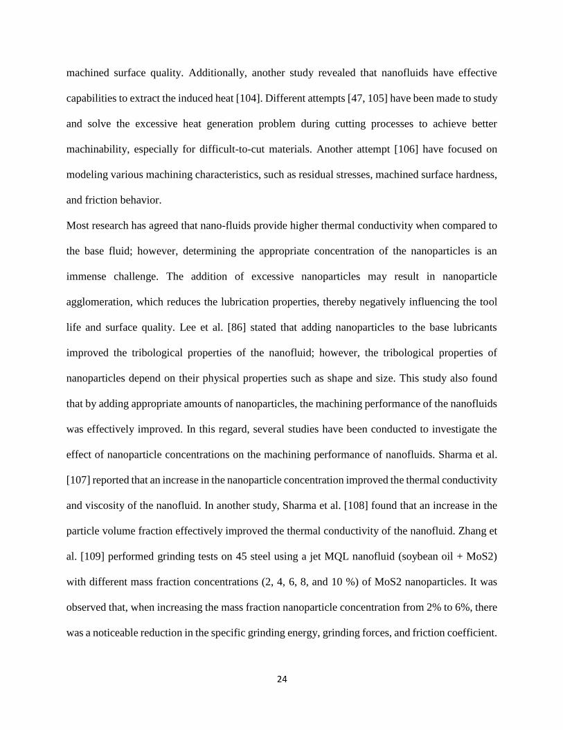
Table 2.1: Summary of available research on MQL and MQCL coolants.
Reference(s) Lubrication Cutting
fluid
Salient
features
Conclusion
Ramana et al.[33], and Yusuf Kaynak [56]Boswell et al. [57], Revankar et al. [65], Deiab et al. [66], Dhar et al.[67] , and Khan et al. [69],
MQL
Vegetable oil
Studied MQL at different cutting parameters and cooling strategies
MQL found to be more effective than dry machining, flood, and cryogenic. MQL showed better results in tool wear, surface roughness, power consumption compared to dry and flood
Chetan et al. [68]
MQL
Vegetable oil (sunflower oil)
Designed mathematical model for predicting the specific cutting energy during machining process under MQL
The increase in pressure and flow rate of MQL reduced the friction at chip-tool interface hence helps to reduce the specific cutting energy. High feed rate increases the sliding speed over the tool rake face and there by reduces the coefficient friction.
Ginting et al. [70]
MQL
Vegetable oil
Compared the sustainability and machining cost between the MQL and conventional flood
MQL less cost in which save cost of a huge amount of cutting fluid, carbon cost, and save the disposal process. MQL can be replaced the flood cooling because it’s more sustainable strategy.
Raza et al. [64] Revuru et al. [77]
MQL & MQCL
Vegetable oil & Vegetable oil +
cold air
Investigated the effect of 6 cooling strategies on tool wear
MQL and MQCL improved the tool life and machined surface quality compared to other cooling strategies
Zhang et al. [78]
MQCL
Biodegradable vegetable oil +
cold air
Study the relationship between tool wear propagation and cutting forces during milling Inconel 718
The use of MQCL increased the tool life and reduced the cutting forces. MQCL method can be an effective alternative coolant to pure MQL method.
Boswell et al. [79]
MQCL
Vegetable oil +
cold air
Study the effect of different cooling methods on machining results
MQL and MQCL are provided reasonable surface quality and better cutting performance compare to dry, flood, and cooled air.
Su et al. [80]
MQL & CAMQL
Cooled air -20 oC + UNILUB
2032
Compared the machining performance of CAMQL to cooled air, pure MQL, and dry machining
The CAMQL approach showed a better tool life and chip formation results during machining Inconel 718 compared to dry condition and classical MQL. CAMQL can be an environment friendliness cooling approach.
28
28
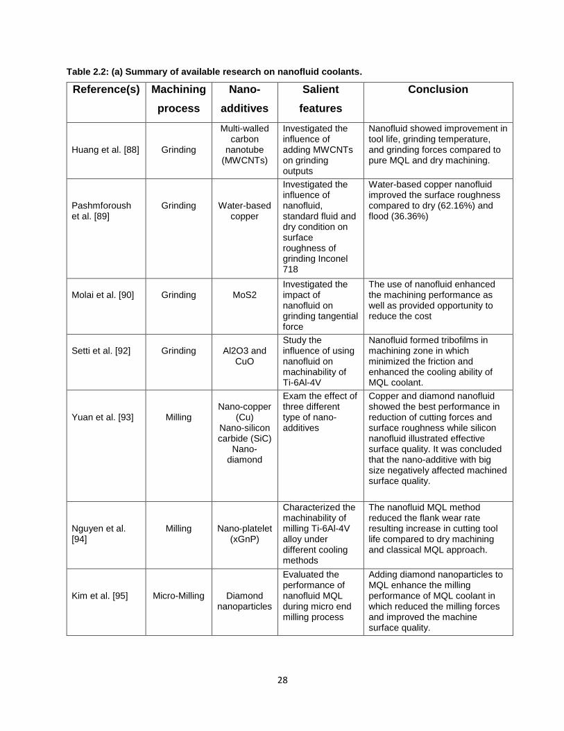
Table 2.2: (a) Summary of available research on nanofluid coolants.
Reference(s) Machining
process
Nano-
additives
Salient
features
Conclusion
Huang et al. [88]
Grinding
Multi-walled carbon
nanotube (MWCNTs)
Investigated the influence of adding MWCNTs on grinding outputs
Nanofluid showed improvement in tool life, grinding temperature, and grinding forces compared to pure MQL and dry machining.
Pashmforoush et al. [89]
Grinding
Water-based copper
Investigated the influence of nanofluid, standard fluid and dry condition on surface roughness of grinding Inconel 718
Water-based copper nanofluid improved the surface roughness compared to dry (62.16%) and flood (36.36%)
Molai et al. [90]
Grinding
MoS2
Investigated the impact of nanofluid on grinding tangential force
The use of nanofluid enhanced the machining performance as well as provided opportunity to reduce the cost
Setti et al. [92]
Grinding
Al2O3 and
CuO
Study the influence of using nanofluid on machinability of Ti-6Al-4V
Nanofluid formed tribofilms in machining zone in which minimized the friction and enhanced the cooling ability of MQL coolant.
Yuan et al. [93]
Milling
Nano-copper
(Cu) Nano-silicon carbide (SiC)
Nano-diamond
Exam the effect of three different type of nano-additives
Copper and diamond nanofluid showed the best performance in reduction of cutting forces and surface roughness while silicon nanofluid illustrated effective surface quality. It was concluded that the nano-additive with big size negatively affected machined surface quality.
Nguyen et al. [94]
Milling
Nano-platelet (xGnP)
Characterized the machinability of milling Ti-6Al-4V alloy under different cooling methods
The nanofluid MQL method reduced the flank wear rate resulting increase in cutting tool life compared to dry machining and classical MQL approach.
Kim et al. [95]
Micro-Milling
Diamond nanoparticles
Evaluated the performance of nanofluid MQL during micro end milling process
Adding diamond nanoparticles to MQL enhance the milling performance of MQL coolant in which reduced the milling forces and improved the machine surface quality.
29
29
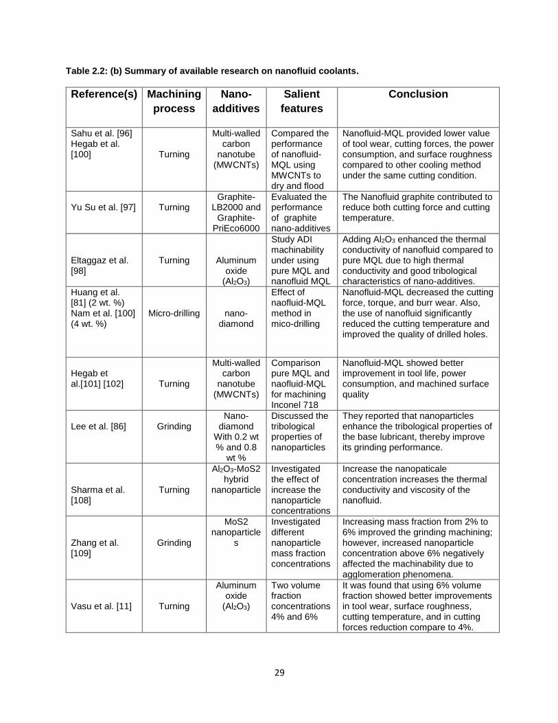
Table 2.2: (b) Summary of available research on nanofluid coolants.
Reference(s) Machining
process
Nano-
additives
Salient
features
Conclusion
Sahu et al. [96] Hegab et al. [100]
Turning
Multi-walled carbon
nanotube (MWCNTs)
Compared the performance of nanofluid-MQL using MWCNTs to dry and flood
Nanofluid-MQL provided lower value of tool wear, cutting forces, the power consumption, and surface roughness compared to other cooling method under the same cutting condition.
Yu Su et al. [97]
Turning
Graphite-LB2000 and
Graphite-PriEco6000
Evaluated the performance of graphite nano-additives
The Nanofluid graphite contributed to reduce both cutting force and cutting temperature.
Eltaggaz et al. [98]
Turning
Aluminum oxide
(Al2O3)
Study ADI machinability under using pure MQL and nanofluid MQL
Adding Al2O3 enhanced the thermal conductivity of nanofluid compared to pure MQL due to high thermal conductivity and good tribological characteristics of nano-additives.
Huang et al. [81] (2 wt. %) Nam et al. [100] (4 wt. %)
Micro-drilling
nano-diamond
Effect of naofluid-MQL method in mico-drilling
Nanofluid-MQL decreased the cutting force, torque, and burr wear. Also, the use of nanofluid significantly reduced the cutting temperature and improved the quality of drilled holes.
Hegab et al.[101] [102]
Turning
Multi-walled carbon
nanotube (MWCNTs)
Comparison pure MQL and naofluid-MQL for machining Inconel 718
Nanofluid-MQL showed better improvement in tool life, power consumption, and machined surface quality
Lee et al. [86]
Grinding
Nano-diamond
With 0.2 wt % and 0.8
wt %
Discussed the tribological properties of nanoparticles
They reported that nanoparticles enhance the tribological properties of the base lubricant, thereby improve its grinding performance.
Sharma et al. [108]
Turning
Al2O3-MoS2 hybrid
nanoparticle
Investigated the effect of increase the nanoparticle concentrations
Increase the nanopaticale concentration increases the thermal conductivity and viscosity of the nanofluid.
Zhang et al. [109]
Grinding
MoS2 nanoparticle
s
Investigated different nanoparticle mass fraction concentrations
Increasing mass fraction from 2% to 6% improved the grinding machining; however, increased nanoparticle concentration above 6% negatively affected the machinability due to agglomeration phenomena.
Vasu et al. [11]
Turning
Aluminum oxide
(Al2O3)
Two volume fraction concentrations 4% and 6%
It was found that using 6% volume fraction showed better improvements in tool wear, surface roughness, cutting temperature, and in cutting forces reduction compare to 4%.
30
30
Chapter 3: Research Methodology
3. 1 Introduction
The experimental approaches and pieces of equipment that were used in the data acquisition of the
experimental study are presented in this chapter. The experimental tests were conducted to study
the cutting performance of ADI and Ti-6Al-4V titanium alloy utilizing a sustainable nanofluid-
MQL vegetable oil cooling strategy.
This chapter presents the details of the experimental techniques and methods used during the
current study. This chapter also provides information about the design of the experiments, the
cutting tool and workpiece materials used, and the experimental setups and the devices employed
to record and determine the cutting parameters and output results.
3.2 Design of Experiments (DOE)
Any material machining process is controlled by a number of factors [114]. These operation
parameters have a governing effect on the machining process. Thus, an investigation of the how
to control these parameters is important to make the cutting process more efficient. A systematic
method known as design of experiments (DOE) is used to investigate the effect of the governing
parameters on the output of the machining operations [114,115]. Using DOE, test matrices were
developed to evaluate cutting process outputs, such as machined surface roughness (Ra) and
cutting tool wear. DOE is also used to determine power/energy consumption when machining
difficult-to-cut materials, e.g., austempered ductile iron (ADI) and titanium alloys (Ti-6Al-4V). It
is also an approach used to explore and understand the cause and effects of the relationships in a
certain operation. The design of experiments technique consists of the following features:
31
31
Planning stage: This phase deals selecting activities related to the problem statement, the research
objectives and aims, the machining of the test matrix with different levels of variables, and the
different experimental setups.
Procedure stage: This stage involves conducting the experiments and collecting the output
parameters in order to evaluate effectiveness of the cutting operation.
Results and analysis: The findings and conclusions from the procedure stage are then plotted by
analyzing the data from the machining experiments. In order to validate and confirm the
conclusion, further machining tests are often required.
3.3 Planning of Experiments
Machining tests were carried out using different cooling strategies, on a CNC HAAS machine.
These strategies included the dry machining, the conventional flood, a vegetable oil- based MQL,
and a vegetable oil-based nanofluid MQL. In the current study, the steps of the DOE were as
follows:
1. Problem statement: this study intends to study the machinability of two difficult-to-cut
materials (ADI and Ti-6Al-4V alloy), to investigate the effect of a sustainable cooling
strategy (vegetable oil-based nanofluid-MQL), to improve the FEM numerical model to
predict the generated heat on the machining tool, and to investigate the ability of the CFD
simulation to predict the heat removal ability of the MQL technique.
2. Aims and objectives: the purpose of this study to investigate the potential of using a
sustainable coolant (a nanofluid-MQL) as an alternative to the conventional flood method
when machining ADI and Ti-6Al-4V alloy. Another goal is to develop a model that would
utilize both finite element model (FEM) to simulate cutting heat distribution on the cutting
32
32
tool and computational fluid dynamics (CFD) to simulate the influence of the MQL coolant
on the machining environment.
3. Identification of the effect of processing parameters: this study considers input cutting
variables, included cutting speed, feed rate, depth of cut, and cooling strategies for
machining, as well as cutting outputs included surface roughness, cutting forces, wear
mechanisms, tool wear, power consumption, and cutting temperature. The nanoparticle
concentration is an additional parameter for the nanofluid-MQL cooling approach.
4. Selecting of machining conditions: this study intends to choose both suitable and
recommended cutting variables in experiment matrix.
5. Improvement of numerical models: this research intends to improve the FEM and CFD
models to predict the effecting parameters such as cutting energy, cutting forces, chip
formation, and cutting tool tip temperature.
6. Implementation of experiments: experimental setups are used to collect sets of experimental
data.
7. Analysis of results: an analysis of the collected data is performed utilizing the proper
analysis methods and interpreting the findings. Also, some experimental data are utilized to
validate the numerical models.
3.3.1 Cutting Tool and Workpiece Materials
Machinability refers to the ease of machining a material. The term is relative, and various indices
such as machined surface quality, tool life, and power consumption can be used to rate it. Because
of the number of possible cutting process variables and their ranges, evaluating machinability often
entails a large number of experiments that are time consuming and expensive. When machining
any material, its properties should be considered. In this research, the workpiece materials used in
33
33
the turning trials were two difficult-to-cut materials: ADI grade 2 and Ti-6Al-4V titanium alloy.
Stock of these materials was available in cylindrical form.
3.3.1.1 Austempered Ductile Iron (ADI)
Tables 3.1 and 3.2 illustrate the chemical composition (wt. %) of ADI grade 2 and its mechanical
properties respectively. Mechanical properties of ADI can be attributed to the high carbon
austenite in its ausferritic matrix (ferrite and carbon-enriched austenite) formed after the
austempering treatment process for casting ADI [11]. Additionally, some researchers have
reported that alloying elements added during casting, austenitizing, and austempering temperatures
contribute to the variations in ADI’s mechanical properties [116-119].
Table 3.1: Percent weight chemical compositions of ADI grade 2 (wt %). [120]
Element Wt. % Element Wt. % Element Wt. %
C 2.8 Mn 0.4 Mo -
Si 2.4 Mg 0.03
Cu 0.6 Cr 0.02
Table 3.2: ASTM A897/897M-02 mechanical properties of ADI grade 2. [121]
Property Value Property Value
Tensile Strength 1050 (MPa) Impact Energy 80 (J)
Yield Strength 700 (MPa) Typical Hardness 340 (BHN)
Young’s Modulus 157.9 (GPa) Elongation (%) 7
34
34
3.3.1.2 Ti-6Al-4V Titanium Alloy
Ti-6Al-4V titanium alloy was used as a workpiece material in this research. The chemical
composition and mechanical properties of this difficult-to-cut material are shown in Tables 3.3
and 3.4 respectively.
Table 3.3: Chemical compositions of Ti-6Al-4V (wt %). [29]
Element Wt. % Element Wt. % Element Wt. %
Ti Balance C 0.1 N 0.05
Al 5.5-6.7 Fe 0.3 H 0.0125
V 3.5-4.5 O 0.2
Table 3.4: Ti-6Al-4V titanium alloy mechanical properties (at room temperature). [115]
Property Value Property Value
Tensile Strength 993 (MPa) Poisson´s ratio 0.34
Yield Strength 830 (MPa) Hardness (HRC) 36
Young’s Modulus 114 (GPa) Elongation (%) 14
3.3.1.3 Turning Cutting Tool Inserts
The machining tests for turning ADI grade 2 and Ti-6Al-4V alloy were performed using coated
and uncoated carbide inserts. The turning tool inserts were chosen based on Sandvik Coromant´s
recommendations [122]. The specifications of the turning cutting inserts are described in the
following sections.
35
35
A) - Coated Carbide CNMG120416MR (ISO)
This cutting insert has a substrate consisting of an HC with good resistance for plastic
deformation, and its nose radius is 1.588 mm (see Figure 3.1). It has a thin physical vapour
deposition (PVD) consisting of a (Ti,Al)N+(Al,Cr)2O3 coating with a good adhesion, toughness,
and wear resistance. This insert is an excellent heat resistant super alloy. It also has a roughing
geometry with a stronger edge line for demanding applications [122].
Figure 3.1 CNMG120416MR (ISO) cutting tool insert. [122]
B) - Uncoated Carbide CNMT 12 04 08-KM H13A (ISO)
This uncoated carbide cutting insert has a nose radius of 0.8mm. It was developed by Sandvik
Coromant (see Figure 3.2). This insert is appropriate for medium to rough turning of alloy cast
irons and malleable irons. It has both a good thermal and mechanical resistance, and offers
outstanding edge security [122].
Figure 3.2 CNMT 12 04 08-KM H13A (ISO) cutting tool insert. [122]
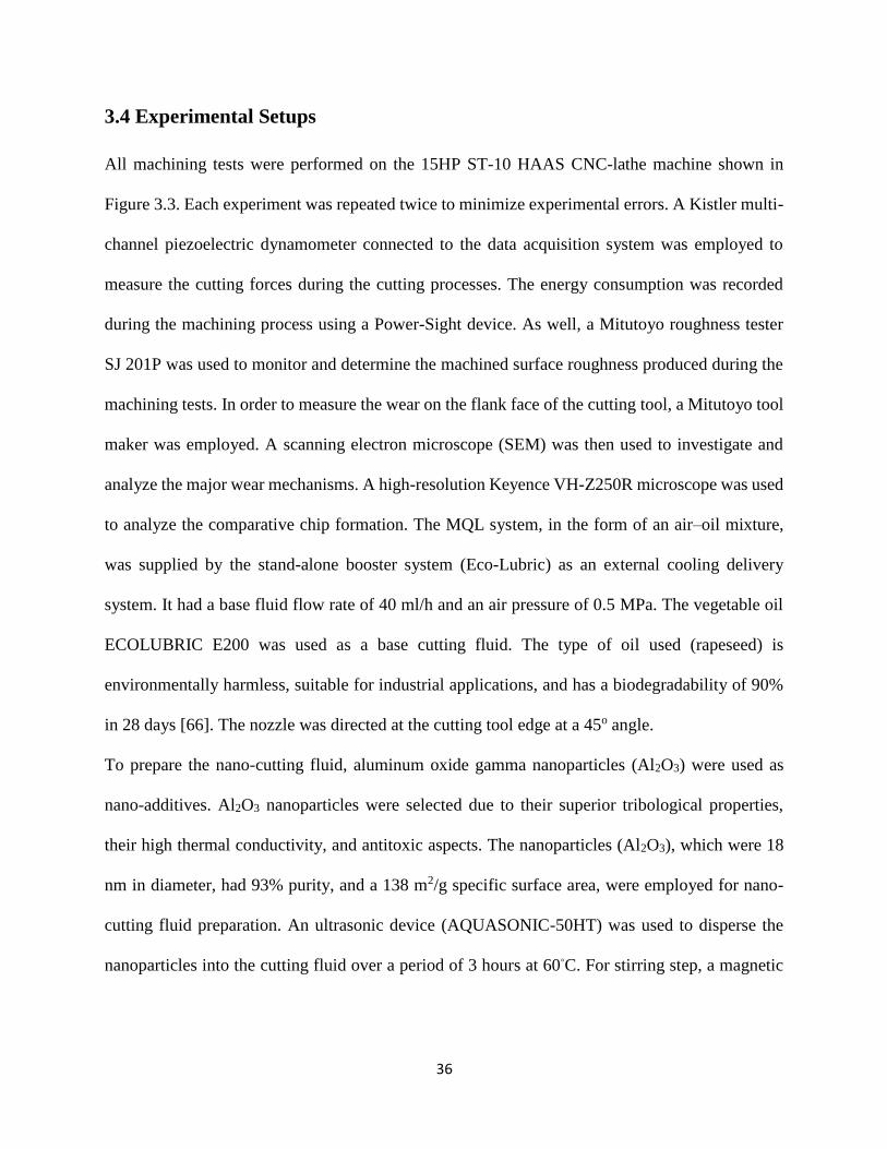
36
36
3.4 Experimental Setups
All machining tests were performed on the 15HP ST-10 HAAS CNC-lathe machine shown in
Figure 3.3. Each experiment was repeated twice to minimize experimental errors. A Kistler multi-
channel piezoelectric dynamometer connected to the data acquisition system was employed to
measure the cutting forces during the cutting processes. The energy consumption was recorded
during the machining process using a Power-Sight device. As well, a Mitutoyo roughness tester
SJ 201P was used to monitor and determine the machined surface roughness produced during the
machining tests. In order to measure the wear on the flank face of the cutting tool, a Mitutoyo tool
maker was employed. A scanning electron microscope (SEM) was then used to investigate and
analyze the major wear mechanisms. A high-resolution Keyence VH-Z250R microscope was used
to analyze the comparative chip formation. The MQL system, in the form of an air–oil mixture,
was supplied by the stand-alone booster system (Eco-Lubric) as an external cooling delivery
system. It had a base fluid flow rate of 40 ml/h and an air pressure of 0.5 MPa. The vegetable oil
ECOLUBRIC E200 was used as a base cutting fluid. The type of oil used (rapeseed) is
environmentally harmless, suitable for industrial applications, and has a biodegradability of 90%
in 28 days [66]. The nozzle was directed at the cutting tool edge at a 45o angle.
To prepare the nano-cutting fluid, aluminum oxide gamma nanoparticles (Al2O3) were used as
nano-additives. Al2O3 nanoparticles were selected due to their superior tribological properties,
their high thermal conductivity, and antitoxic aspects. The nanoparticles (Al2O3), which were 18
nm in diameter, had 93% purity, and a 138 m2/g specific surface area, were employed for nano-
cutting fluid preparation. An ultrasonic device (AQUASONIC-50HT) was used to disperse the
nanoparticles into the cutting fluid over a period of 3 hours at 60◦C. For stirring step, a magnetic
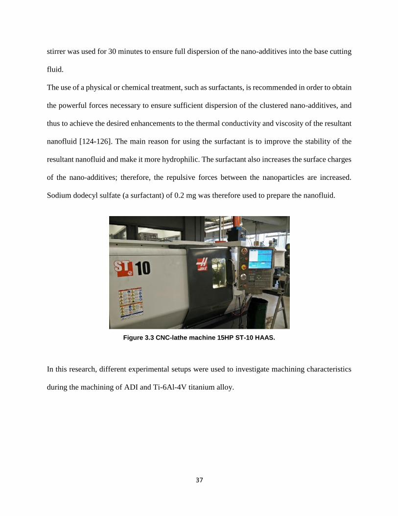
37
37
stirrer was used for 30 minutes to ensure full dispersion of the nano-additives into the base cutting
fluid.
The use of a physical or chemical treatment, such as surfactants, is recommended in order to obtain
the powerful forces necessary to ensure sufficient dispersion of the clustered nano-additives, and
thus to achieve the desired enhancements to the thermal conductivity and viscosity of the resultant
nanofluid [124-126]. The main reason for using the surfactant is to improve the stability of the
resultant nanofluid and make it more hydrophilic. The surfactant also increases the surface charges
of the nano-additives; therefore, the repulsive forces between the nanoparticles are increased.
Sodium dodecyl sulfate (a surfactant) of 0.2 mg was therefore used to prepare the nanofluid.
Figure 3.3 CNC-lathe machine 15HP ST-10 HAAS.
In this research, different experimental setups were used to investigate machining characteristics
during the machining of ADI and Ti-6Al-4V titanium alloy.
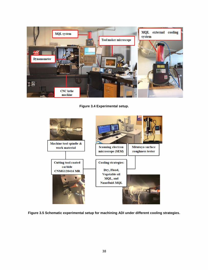
38
38
Figure 3.4 Experimental setup.
Figure 3.5 Schematic experimental setup for machining ADI under different cooling strategies.
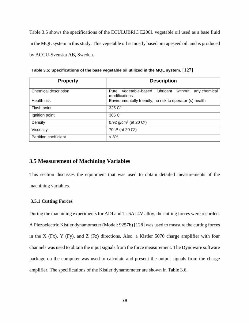
39
39
Table 3.5 shows the specifications of the ECULUBRIC E200L vegetable oil used as a base fluid
in the MQL system in this study. This vegetable oil is mostly based on rapeseed oil, and is produced
by ACCU-Svenska AB, Sweden.
Table 3.5: Specifications of the base vegetable oil utilized in the MQL system. [127]
Property Description
Chemical description Pure vegetable-based lubricant without any chemical modifications.
Health risk Environmentally friendly; no risk to operator-(s) health
Flash point 325 Co
Ignition point 365 Co
Density 0.92 g/cm3 (at 20 Co)
Viscosity 70cP (at 20 Co)
Partition coefficient < 3%
3.5 Measurement of Machining Variables
This section discusses the equipment that was used to obtain detailed measurements of the
machining variables.
3.5.1 Cutting Forces
During the machining experiments for ADI and Ti-6Al-4V alloy, the cutting forces were recorded.
A Piezoelectric Kistler dynamometer (Model: 9257b) [128] was used to measure the cutting forces
in the X (Fx), Y (Fy), and Z (Fz) directions. Also, a Kistler 5070 charge amplifier with four
channels was used to obtain the input signals from the force measurement. The Dynoware software
package on the computer was used to calculate and present the output signals from the charge
amplifier. The specifications of the Kistler dynamometer are shown in Table 3.6.
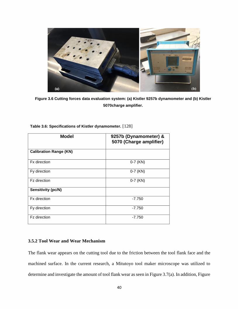
40
40
Figure 3.6 Cutting forces data evaluation system: (a) Kistler 9257b dynamometer and (b) Kistler
5070charge amplifier.
Table 3.6: Specifications of Kistler dynamometer. [128]
Model 9257b (Dynamometer) & 5070 (Charge amplifier)
Calibration Range (KN)
Fx direction 0-7 (KN)
Fy direction 0-7 (KN)
Fz direction 0-7 (KN)
Sensitivity (pc/N)
Fx direction -7.750
Fy direction -7.750
Fz direction -7.750
3.5.2 Tool Wear and Wear Mechanism
The flank wear appears on the cutting tool due to the friction between the tool flank face and the
machined surface. In the current research, a Mitutoyo tool maker microscope was utilized to
determine and investigate the amount of tool flank wear as seen in Figure 3.7(a). In addition, Figure
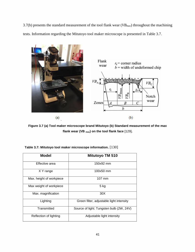
41
41
3.7(b) presents the standard measurement of the tool flank wear (VBmax) throughout the machining
tests. Information regarding the Mitutoyo tool maker microscope is presented in Table 3.7.
Figure 3.7 (a) Tool maker microscope brand Mitutoyo (b) Standard measurement of the max
flank wear (VB max) on the tool flank face [129].
Table 3.7: Mitutoyo tool maker microscope information. [130]
Model Mitutoyo TM 510
Effective area 150x92 mm
X Y range 100x50 mm
Max. height of workpiece 107 mm
Max weight of workpiece 5 kg
Max. magnification 30X
Lighting Green filter, adjustable light intensity
Transmitted Source of light: Tungsten bulb (2W, 24V)
Reflection of lighting Adjustable light intensity
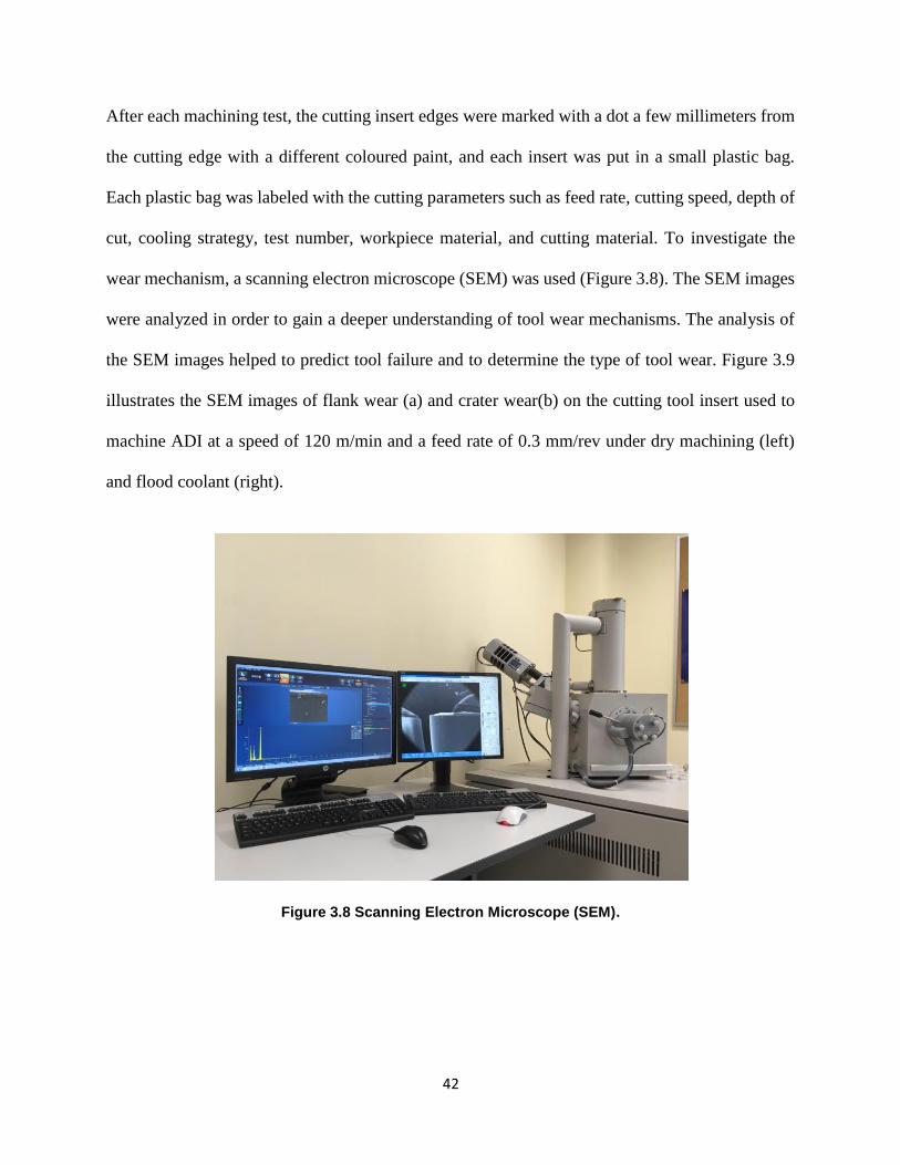
42
42
After each machining test, the cutting insert edges were marked with a dot a few millimeters from
the cutting edge with a different coloured paint, and each insert was put in a small plastic bag.
Each plastic bag was labeled with the cutting parameters such as feed rate, cutting speed, depth of
cut, cooling strategy, test number, workpiece material, and cutting material. To investigate the
wear mechanism, a scanning electron microscope (SEM) was used (Figure 3.8). The SEM images
were analyzed in order to gain a deeper understanding of tool wear mechanisms. The analysis of
the SEM images helped to predict tool failure and to determine the type of tool wear. Figure 3.9
illustrates the SEM images of flank wear (a) and crater wear(b) on the cutting tool insert used to
machine ADI at a speed of 120 m/min and a feed rate of 0.3 mm/rev under dry machining (left)
and flood coolant (right).
Figure 3.8 Scanning Electron Microscope (SEM).
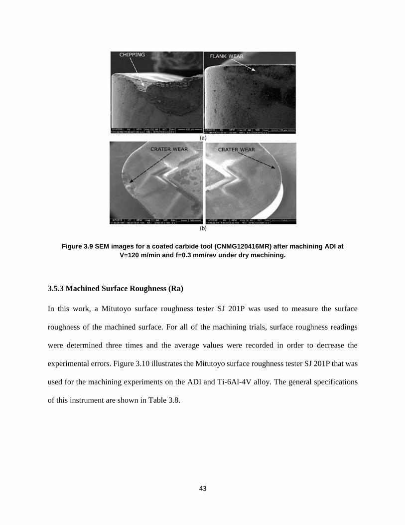
43
43
Figure 3.9 SEM images for a coated carbide tool (CNMG120416MR) after machining ADI at
V=120 m/min and f=0.3 mm/rev under dry machining.
3.5.3 Machined Surface Roughness (Ra)
In this work, a Mitutoyo surface roughness tester SJ 201P was used to measure the surface
roughness of the machined surface. For all of the machining trials, surface roughness readings
were determined three times and the average values were recorded in order to decrease the
experimental errors. Figure 3.10 illustrates the Mitutoyo surface roughness tester SJ 201P that was
used for the machining experiments on the ADI and Ti-6Al-4V alloy. The general specifications
of this instrument are shown in Table 3.8.
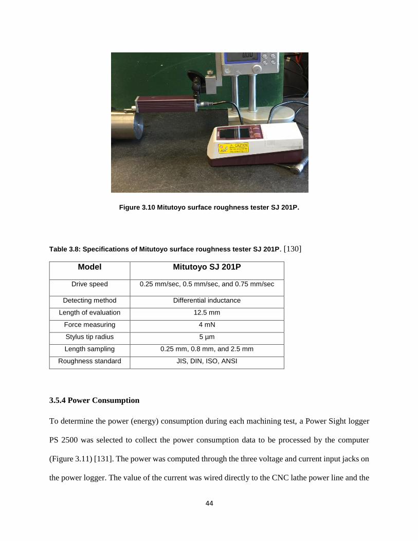
44
44
Figure 3.10 Mitutoyo surface roughness tester SJ 201P.
Table 3.8: Specifications of Mitutoyo surface roughness tester SJ 201P. [130]
Model Mitutoyo SJ 201P
Drive speed 0.25 mm/sec, 0.5 mm/sec, and 0.75 mm/sec
Detecting method Differential inductance
Length of evaluation 12.5 mm
Force measuring 4 mN
Stylus tip radius 5 µm
Length sampling 0.25 mm, 0.8 mm, and 2.5 mm
Roughness standard JIS, DIN, ISO, ANSI
3.5.4 Power Consumption
To determine the power (energy) consumption during each machining test, a Power Sight logger
PS 2500 was selected to collect the power consumption data to be processed by the computer
(Figure 3.11) [131]. The power was computed through the three voltage and current input jacks on
the power logger. The value of the current was wired directly to the CNC lathe power line and the
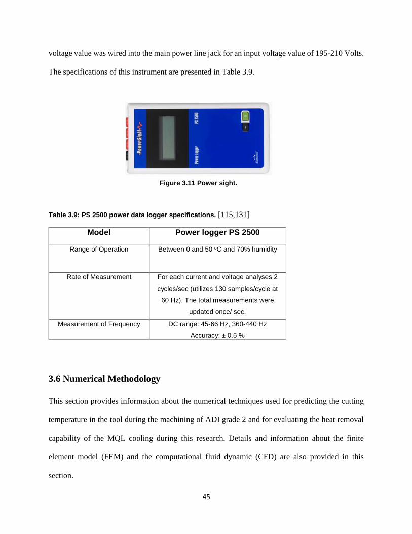
45
45
voltage value was wired into the main power line jack for an input voltage value of 195-210 Volts.
The specifications of this instrument are presented in Table 3.9.
Figure 3.11 Power sight.
Table 3.9: PS 2500 power data logger specifications. [115,131]
Model Power logger PS 2500
Range of Operation
Between 0 and 50 oC and 70% humidity
Rate of Measurement For each current and voltage analyses 2
cycles/sec (utilizes 130 samples/cycle at
60 Hz). The total measurements were
updated once/ sec.
Measurement of Frequency DC range: 45-66 Hz, 360-440 Hz
Accuracy: ± 0.5 %
3.6 Numerical Methodology
This section provides information about the numerical techniques used for predicting the cutting
temperature in the tool during the machining of ADI grade 2 and for evaluating the heat removal
capability of the MQL cooling during this research. Details and information about the finite
element model (FEM) and the computational fluid dynamic (CFD) are also provided in this
section.
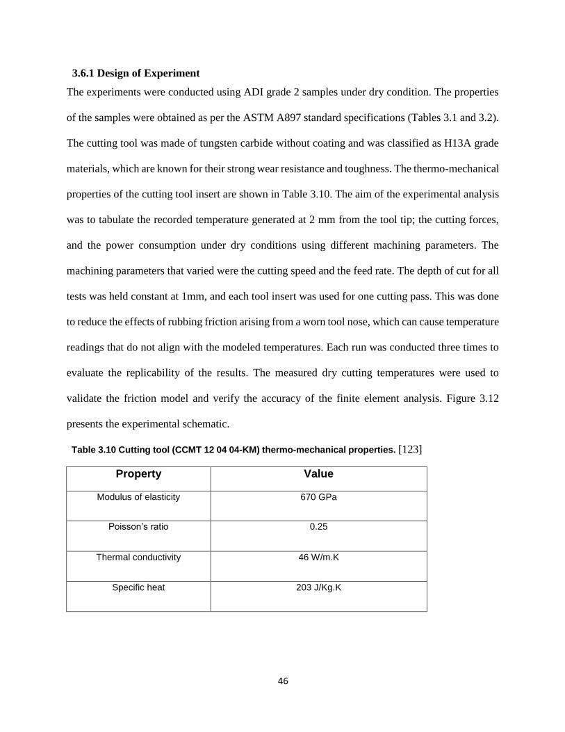
46
46
3.6.1 Design of Experiment
The experiments were conducted using ADI grade 2 samples under dry condition. The properties
of the samples were obtained as per the ASTM A897 standard specifications (Tables 3.1 and 3.2).
The cutting tool was made of tungsten carbide without coating and was classified as H13A grade
materials, which are known for their strong wear resistance and toughness. The thermo-mechanical
properties of the cutting tool insert are shown in Table 3.10. The aim of the experimental analysis
was to tabulate the recorded temperature generated at 2 mm from the tool tip; the cutting forces,
and the power consumption under dry conditions using different machining parameters. The
machining parameters that varied were the cutting speed and the feed rate. The depth of cut for all
tests was held constant at 1mm, and each tool insert was used for one cutting pass. This was done
to reduce the effects of rubbing friction arising from a worn tool nose, which can cause temperature
readings that do not align with the modeled temperatures. Each run was conducted three times to
evaluate the replicability of the results. The measured dry cutting temperatures were used to
validate the friction model and verify the accuracy of the finite element analysis. Figure 3.12
presents the experimental schematic.
Table 3.10 Cutting tool (CCMT 12 04 04-KM) thermo-mechanical properties. [123]
Property Value
Modulus of elasticity 670 GPa
Poisson’s ratio 0.25
Thermal conductivity 46 W/m.K
Specific heat 203 J/Kg.K
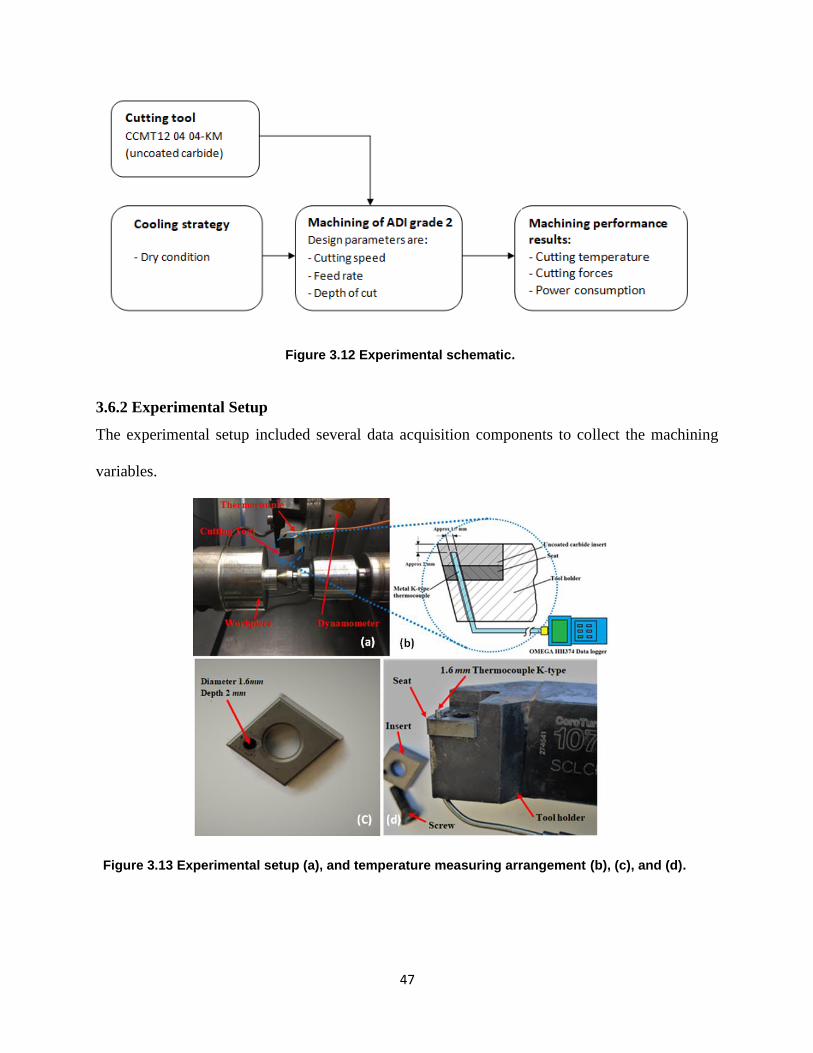
47
47
Figure 3.12 Experimental schematic.
3.6.2 Experimental Setup
The experimental setup included several data acquisition components to collect the machining
variables.
Figure 3.13 Experimental setup (a), and temperature measuring arrangement (b), (c), and (d).
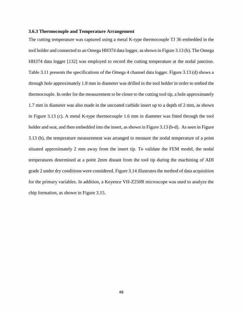
48
48
3.6.3 Thermocouple and Temperature Arrangement
The cutting temperature was captured using a metal K-type thermocouple TJ 36 embedded in the
tool holder and connected to an Omega HH374 data logger, as shown in Figure 3.13 (b). The Omega
HH374 data logger [132] was employed to record the cutting temperature at the nodal junction.
Table 3.11 presents the specifications of the Omega 4 channel data logger. Figure 3.13 (d) shows a
through hole approximately 1.8 mm in diameter was drilled in the tool holder in order to embed the
thermocouple. In order for the measurement to be closer to the cutting tool tip, a hole approximately
1.7 mm in diameter was also made in the uncoated carbide insert up to a depth of 2 mm, as shown
in Figure 3.13 (c). A metal K-type thermocouple 1.6 mm in diameter was fitted through the tool
holder and seat, and then embedded into the insert, as shown in Figure 3.13 (b-d). As seen in Figure
3.13 (b), the temperature measurement was arranged to measure the nodal temperature of a point
situated approximately 2 mm away from the insert tip. To validate the FEM model, the nodal
temperatures determined at a point 2mm distant from the tool tip during the machining of ADI
grade 2 under dry conditions were considered. Figure 3.14 illustrates the method of data acquisition
for the primary variables. In addition, a Keyence VH-Z250R microscope was used to analyze the
chip formation, as shown in Figure 3.15.
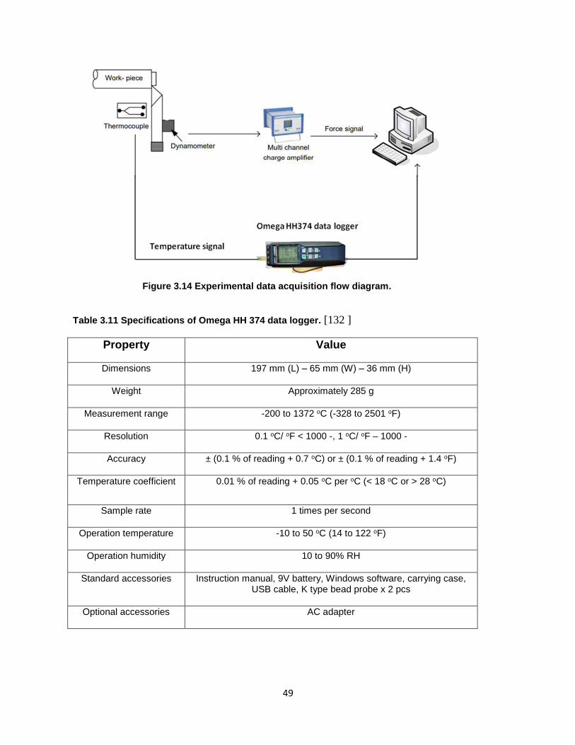
49
49
Figure 3.14 Experimental data acquisition flow diagram.
Table 3.11 Specifications of Omega HH 374 data logger. [132 ]
Property Value
Dimensions 197 mm (L) – 65 mm (W) – 36 mm (H)
Weight Approximately 285 g
Measurement range -200 to 1372 oC (-328 to 2501 oF)
Resolution 0.1 oC/ oF < 1000 -, 1 oC/ oF – 1000 -
Accuracy ± (0.1 % of reading + 0.7 oC) or ± (0.1 % of reading + 1.4 oF)
Temperature coefficient 0.01 % of reading + 0.05 oC per oC (< 18 oC or > 28 oC)
Sample rate 1 times per second
Operation temperature -10 to 50 oC (14 to 122 oF)
Operation humidity 10 to 90% RH
Standard accessories Instruction manual, 9V battery, Windows software, carrying case, USB cable, K type bead probe x 2 pcs
Optional accessories AC adapter

50
50
Figure 3.15 Keyence VH-Z250R microscope.
51
51
Figure 3.16 Thesis methodologies.
52
52
Chapter 4: Results and Discussion
This chapter provides the results from research work that has been published on machining of ADI
grade2 and Ti-6Al-4V titanium alloy. Most of the findings are from appended published papers.
4.1 The Effects of Using Different Coolant strategies on Tool Life and Surface
Roughness when Machining ADI
4.1.1 Introduction
Austempered ductile iron alloys (ADI) are an interesting class of materials because of their unique
microstructure and mechanical properties. Accordingly, there is a growing interest in using ADI
in several applications due to its mechanical properties. However, as with difficult-to-cut materials,
the machinability rating of ADI is low and there is still a need to understand the impact of the
cutting process parameters. Machinability of a material depends not only on its properties and
microstructure, but also on the proper selection and control of process variables. The current
section is focused on performing a machinability analysis of ADI in order to understand the effect
of the cutting process parameters on the machined surface quality and tool life. It also studies the
effect of different coolant strategies. Thus, the motivation of this study is to develop a better
understanding of the influence of cutting parameters and cooling strategy to be able to machine
ADI directly with acceptable tool life and cycle time. The design of experiments technique and
response surface methodology is employed to analyze and model the measured responses. In
addition, the cutting tool wear mechanisms are identified and discussed.
Austempered ductile iron (ADI) grade 2 was used as the workpiece and coated carbide tool
(CNMG120416MR) with 1.6 mm nose radius was used for the cutting tests. Four different coolant
strategies were utilized in this study, namely, dry machining, flood cooling, MQL with vegetable
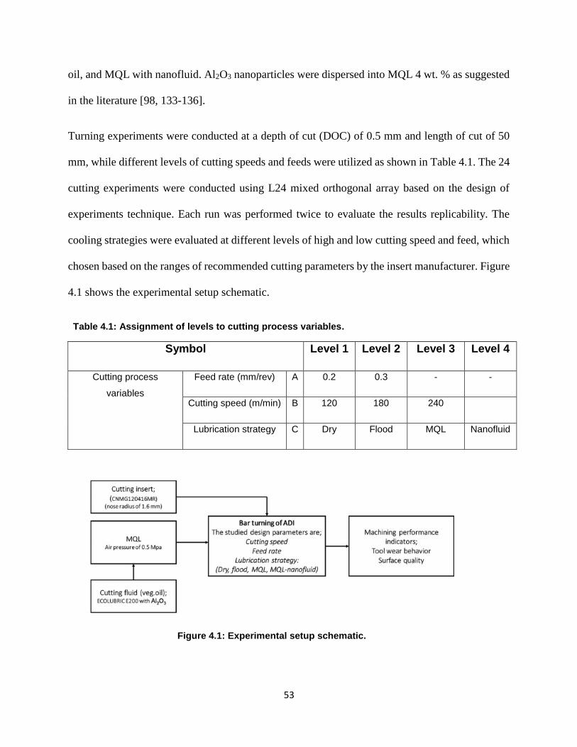
53
53
oil, and MQL with nanofluid. Al2O3 nanoparticles were dispersed into MQL 4 wt. % as suggested
in the literature [98, 133-136].
Turning experiments were conducted at a depth of cut (DOC) of 0.5 mm and length of cut of 50
mm, while different levels of cutting speeds and feeds were utilized as shown in Table 4.1. The 24
cutting experiments were conducted using L24 mixed orthogonal array based on the design of
experiments technique. Each run was performed twice to evaluate the results replicability. The
cooling strategies were evaluated at different levels of high and low cutting speed and feed, which
chosen based on the ranges of recommended cutting parameters by the insert manufacturer. Figure
4.1 shows the experimental setup schematic.
Table 4.1: Assignment of levels to cutting process variables.
Symbol Level 1 Level 2 Level 3 Level 4
Cutting process
variables
Feed rate (mm/rev) A 0.2 0.3 - -
Cutting speed (m/min) B 120 180 240
Lubrication strategy C Dry Flood MQL Nanofluid
Figure 4.1: Experimental setup schematic.
54
54
4.1.2 Results and discussions
The findings of this study were discussed in this section. A maximum flank tool wear of (VB =
0.5 mm) was used as the tool life criteria. The tool life and average surface roughness results are
shown in Table 4.2. The test matrix was developed with the aim of relating the influence of input
parameters to all measured responses.
4.1.2.1 Tool Life and Surface Roughness
The best performance of the cutting tool in terms of tool life was recorded at cutting speed of 120
m/min, feed rate of 0.2 mm/ rev using MQL nanofluid technique as shown Figure 4.2. The 4%
nanofluid coolant showed the highest tool life in comparison to the other employed techniques.
The nanofluid-MQL shows improvement percentages in tool life of 19.4, 4.1, and 30.5% in
comparison with tests performed at same cutting conditions using MQL, flood, and dry techniques,
respectively. Flood coolant shows better results only at cutting speed of 120 m/min and feed rate
of 0.3 mm/rev; however, it is still not an environmentally friendly technique while nanofluid-MQL
is a sustainable technique as it uses a small amount of cutting fluid (environmentally friendly
system).
Several studies have shown that the use of MQL results in a better surface than dry machining [10,
137, 138] which is relatively consistent with that shown in Figure 4.3. The MQL also reduces the
cutting temperature, cutting forces, tool wear, and friction coefficient in comparison with dry
machining. However, the average surface roughness results suggest that the nanofluid appears to
be the best choice when operating at a low feed rate; however, the flood coolant appears to provide
relatively better results at higher feed rate values.
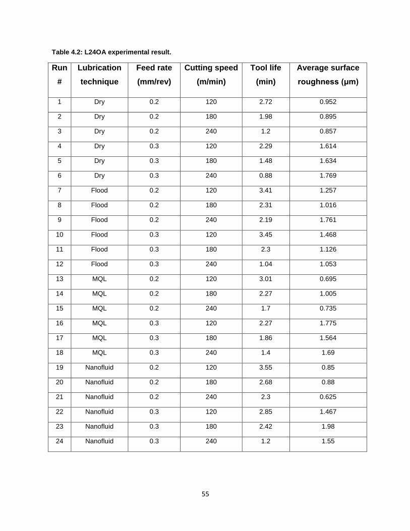
55
55
Table 4.2: L24OA experimental result.
Run
#
Lubrication
technique
Feed rate
(mm/rev)
Cutting speed
(m/min)
Tool life
(min)
Average surface
roughness (μm)
1 Dry 0.2 120 2.72 0.952
2 Dry 0.2 180 1.98 0.895
3 Dry 0.2 240 1.2 0.857
4 Dry 0.3 120 2.29 1.614
5 Dry 0.3 180 1.48 1.634
6 Dry 0.3 240 0.88 1.769
7 Flood 0.2 120 3.41 1.257
8 Flood 0.2 180 2.31 1.016
9 Flood 0.2 240 2.19 1.761
10 Flood 0.3 120 3.45 1.468
11 Flood 0.3 180 2.3 1.126
12 Flood 0.3 240 1.04 1.053
13 MQL 0.2 120 3.01 0.695
14 MQL 0.2 180 2.27 1.005
15 MQL 0.2 240 1.7 0.735
16 MQL 0.3 120 2.27 1.775
17 MQL 0.3 180 1.86 1.564
18 MQL 0.3 240 1.4 1.69
19 Nanofluid 0.2 120 3.55 0.85
20 Nanofluid 0.2 180 2.68 0.88
21 Nanofluid 0.2 240 2.3 0.625
22 Nanofluid 0.3 120 2.85 1.467
23 Nanofluid 0.3 180 2.42 1.98
24 Nanofluid 0.3 240 1.2 1.55
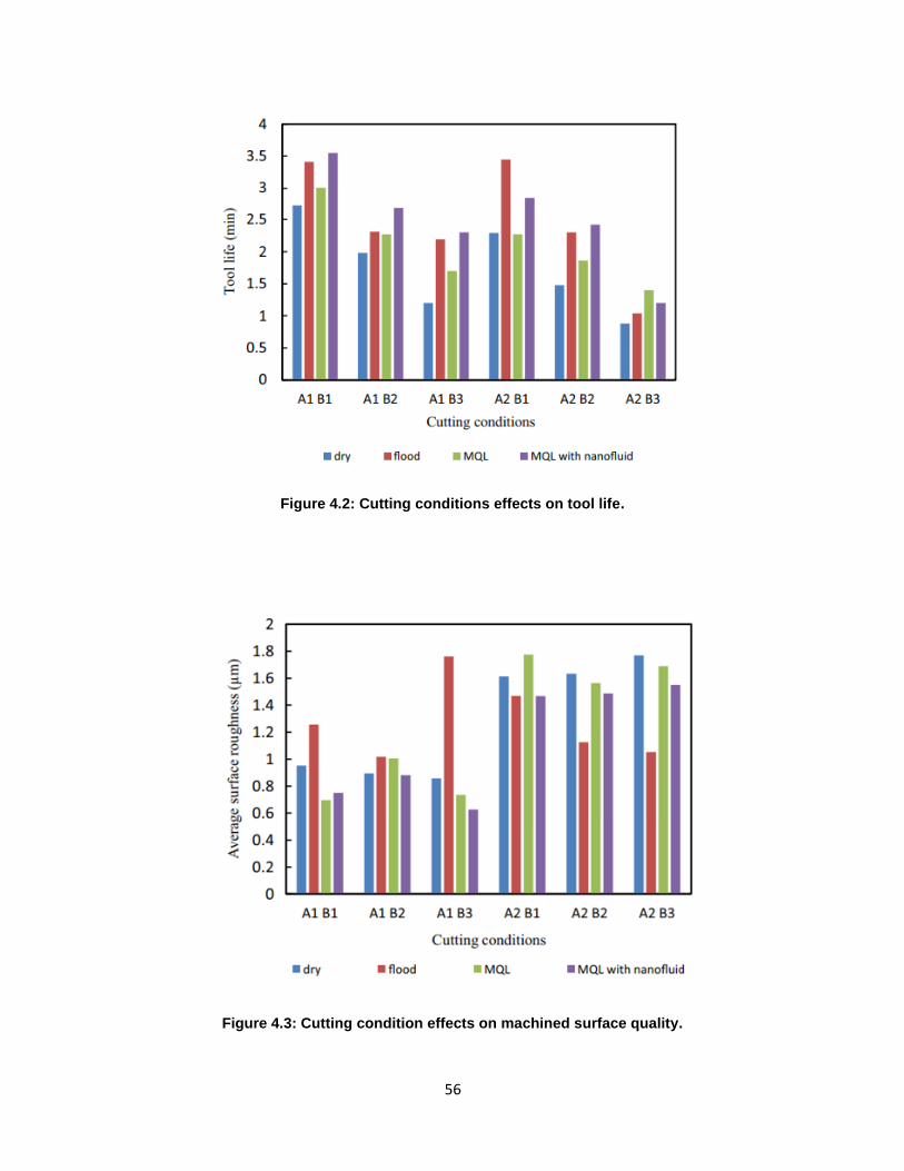
56
56
Figure 4.2: Cutting conditions effects on tool life.
Figure 4.3: Cutting condition effects on machined surface quality.
57
57
Additionally, from Figures 4.2 and 4.3, it can be seen that the shorter tool life and the coarser
surface finish were obtained when machining ADI at the highest levels of cutting speed and feed
(240 m/min and 0.3 mm/rev) for all employed cooling strategies. Thus, compared to the tests
performed using lowest levels of cutting speed and feed rate, the tool life values are decreased by
65, 64, 52, and 63% for dry, flood, MQL, and nanofluid, respectively. Consequently, the surface
roughness values are increased by 46, 58, and 51% for dry machining, MQL, and nanofluid,
respectively under using the highest levels for both cutting speed and feed rate.
Generally, the appropriate chip breaking features and potential low machining temperatures make
cast iron materials proper for machining processes, which are conducted under dry condition.
However, Klocke et al. [139] pointed out that in many cases the use of cooling strategy was
significant in machining ADI and was associated with some substantial benefits which agree with
the results shown in Figure 4. 2. The flood coolant has an advantage in terms of chip clearing as
the high liquid pressure at the cutting zone helps to move the chips away of the cutting tool, thereby
avoiding the recut chips phenomenon and eliminating a crater wear which could damage the
machined surface and dull the cutting tool faster.
Many researchers [140-142] have reported that adding nanoparticles into a base fluid offers a
reasonable reduction in friction and greatly enhances its wettability. Different mechanisms were
discovered to clarify the enhancement in lubricity of nanofluids, including effect of ball bearing,
tribo-film formation, mending, and polishing effects [143]. In this work, the nanofluid
enhancements can be attributed to the thermal conductivity improvements of the MQL due to the
proper dispersion of Al2O3 nanoparticles into the base cutting fluid which enhances the resultant
thermal conductivity value in comparison with the base lubricants because of the remarkable
58
58
properties of the added Al2O3 nanoparticles (e.g., wear resistance, and excellent thermal
conductivity).
The resultant nanofluid was atomized in the MQL system through the applied compressed air,
forming a fine mist surrounded with a base cutting fluid film [144]. This mist has the ability to
penetrate into the chip-tool interfere zone and forming a tribo-film which helps in absorbing the
generated heat and reducing the induced friction. The mentioned characteristics enormously
improve the cooling and lubrication properties and retain the cutting tool hardness for a longer
time as have been confirmed by Khandekar et al. [143]. In addition to the previous point, using
MQL-nanofluid reduced the friction more effectively since the dispersed nanoparticles serve as
spacers, eliminating the contact between tool and workpiece [145]. Thus, the MQL-nanofluid
offers promising results in terms of tool life improvement (ranging between 15 and 21%) in
comparison with tests done using classical MQL. Furthermore, an important point to be considered
is that in most machining levels, when 4% gamma-Al2O3 nanoparticles were dispersed into
vegetable oil, the surface roughness values were decreased.
This improvement was at a value higher than that of pure MQL, except in the case of low-feed-
low-speed level where the levels of improvement for both cases are the same as shown in Figure
4.3. The findings show that the best surface roughness was 0.625 μm for MQL + 4% gamma-Al2O3
nanoparticles at cutting speed of 240 m/min and feed rate of 0.2 mm/rev. The nanofluid-MQL
showed improvement in surface quality of 15, 58, and 27.1% in comparison with tests performed
at same cutting conditions using MQL, flood, and dry techniques, respectively. The main goal of
using nanoparticles was to enhance a heat transfer coefficient and thermal conductivity of the base
fluid as well as lubricate the cutting zone during machining process. Because the nanoparticles
have a nano-metric sizes and spherical shapes, they can be sprayed into the cutting zone, and then
59
59
be inset into fractured grooves and pores in the cutting zone, as well as between the chips and
cutting tool. Then the nanoparticles lubricate the cutting zone which can largely reduce the friction
force, and then the cutting forces. The better surface obtained by using nanofluid was probably
due to the more effective lubrication and cooling of the tool/workpiece interface and wettability of
work material.
4.1.2.2 ANOVA Analysis
Table 4.3 displays the ANOVA results for the average surface roughness. It showed that the
interaction effect between the lubrication strategy and feed rate was the only significant variable
at 99% confidence level. Additionally, the interaction effect between the cutting speed and feed
rate, and the feed rate effect separately were not significant above 90%; however, they still have
acceptable statistical summation about 1.9 and 1.95, respectively (Table 4.4). The lubrication
technique only did not show a significant effect on the resultant surface roughness; however, it
still has a promising combined effect with the feed rate as their interaction provided the highest
statistical summation. Plot of the interaction effect between the lubrication strategy and cutting
feed rate for the measured average surface roughness data showed the optimum level, which
provided the lowest summation of average surface roughness as shown in Figure 4.4. It was
observed that using MQL with nanofluid and cutting feed rate of 0.2 mm/rev provided the optimal
average surface roughness performance (i.e., A1.C4).
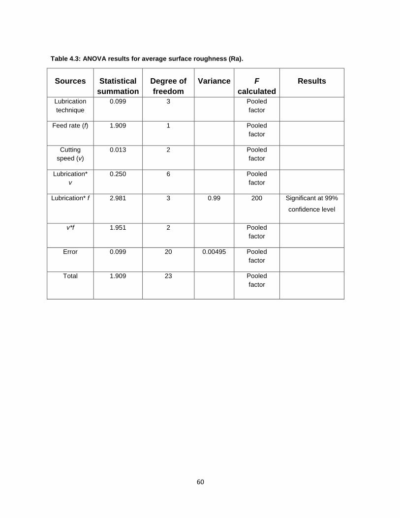
60
60
Table 4.3: ANOVA results for average surface roughness (Ra).
Sources Statistical
summation
Degree of
freedom
Variance F
calculated
Results
Lubrication
technique
0.099 3 Pooled
factor
Feed rate (f) 1.909 1 Pooled
factor
Cutting
speed (v)
0.013 2 Pooled
factor
Lubrication*
v
0.250 6 Pooled
factor
Lubrication* f 2.981 3 0.99 200 Significant at 99%
confidence level
v*f 1.951 2 Pooled
factor
Error 0.099 20 0.00495 Pooled
factor
Total 1.909 23 Pooled
factor
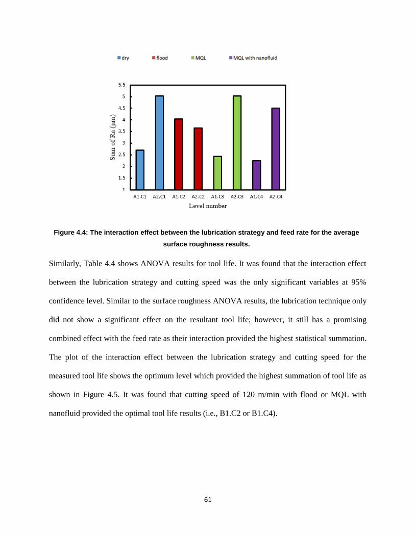
61
61
Figure 4.4: The interaction effect between the lubrication strategy and feed rate for the average
surface roughness results.
Similarly, Table 4.4 shows ANOVA results for tool life. It was found that the interaction effect
between the lubrication strategy and cutting speed was the only significant variables at 95%
confidence level. Similar to the surface roughness ANOVA results, the lubrication technique only
did not show a significant effect on the resultant tool life; however, it still has a promising
combined effect with the feed rate as their interaction provided the highest statistical summation.
The plot of the interaction effect between the lubrication strategy and cutting speed for the
measured tool life shows the optimum level which provided the highest summation of tool life as
shown in Figure 4.5. It was found that cutting speed of 120 m/min with flood or MQL with
nanofluid provided the optimal tool life results (i.e., B1.C2 or B1.C4).
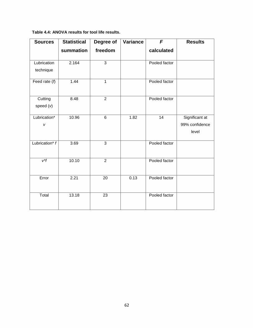
62
62
Table 4.4: ANOVA results for tool life results.
Sources Statistical
summation
Degree of
freedom
Variance F
calculated
Results
Lubrication
technique
2.164 3 Pooled factor
Feed rate (f) 1.44 1 Pooled factor
Cutting
speed (v)
8.48 2 Pooled factor
Lubrication*
v
10.96 6 1.82 14 Significant at
99% confidence
level
Lubrication* f 3.69 3 Pooled factor
v*f 10.10 2 Pooled factor
Error 2.21 20 0.13 Pooled factor
Total 13.18 23 Pooled factor
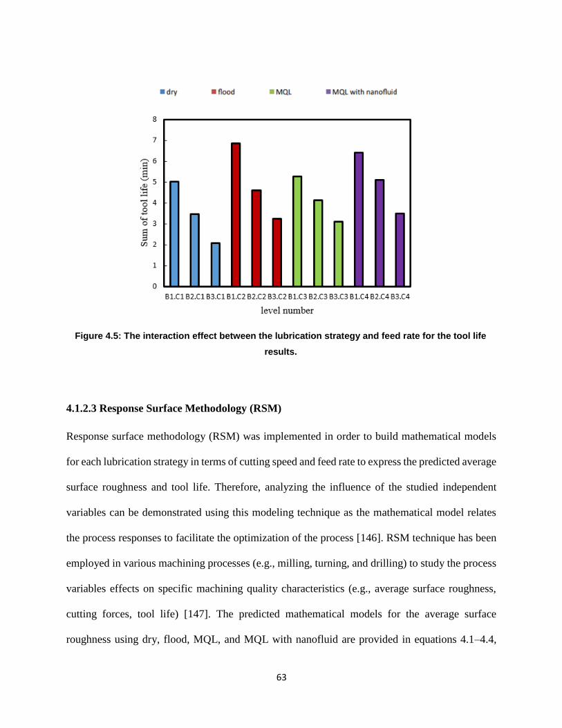
63
63
Figure 4.5: The interaction effect between the lubrication strategy and feed rate for the tool life
results.
4.1.2.3 Response Surface Methodology (RSM)
Response surface methodology (RSM) was implemented in order to build mathematical models
for each lubrication strategy in terms of cutting speed and feed rate to express the predicted average
surface roughness and tool life. Therefore, analyzing the influence of the studied independent
variables can be demonstrated using this modeling technique as the mathematical model relates
the process responses to facilitate the optimization of the process [146]. RSM technique has been
employed in various machining processes (e.g., milling, turning, and drilling) to study the process
variables effects on specific machining quality characteristics (e.g., average surface roughness,
cutting forces, tool life) [147]. The predicted mathematical models for the average surface
roughness using dry, flood, MQL, and MQL with nanofluid are provided in equations 4.1–4.4,
64
64
respectively. Similarly, the tool life models were developed as shown in equations 4.5–4.8,
respectively. Also, the coefficients of correlations for the all studied cases were determined and
results were listed as in Table 4.5. In order to validate the proposed mathematical models, average
model accuracy is calculated for each case as shown in equation 4.9.
Ra) dry = 7.71 f + 0.000025 v – 0.6856 …………………………………………..................................... (4.1)
Ra) flood = 12.945 f – 0.0118 v – 0.0765 fv + 0.000087v2 + 0.704 … … … … … … … … (4.2)
Ra) MQL = 10.521 f + 0.00849 v – 0.0104 fv – 0.0000168 v2– 1.858 … … … … … . . … (4.3)
Ra) nanofluid = 4.18 f – 0.0078 v + 0.0256 fv + 0.28 ………………...(4.4)
Tool life) dry = – 4.166 f – 0.0121 v + 4.9975 ……………………………….…(4.5)
Tool life) flood = 14.11 f – 0.012 v – 0.0991 fv + 0.00006 v2 + 3.455 … … … … … … … . . . . (4.6)
Tool life) MQL = – 11.43 F − 0.021 v + 0.0366 fv + 0.0000083 v2 + 6.828 … … … . … . (4.7)
Tool life) nanofluid = – 0.086 f – 0.0037 v – 0.033 fv + 4.89 … … … … … … … . . … … . … . (4.8)
Average Model accuracy = ∑ 1 −
Abs(experimental value − predicted value)experimental value
ni=1
n … … . (4.9)
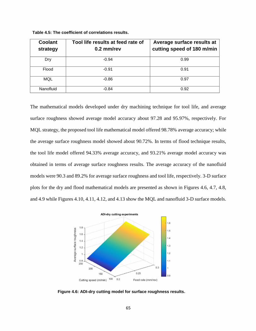
65
65
Table 4.5: The coefficient of correlations results.
Coolant
strategy
Tool life results at feed rate of
0.2 mm/rev
Average surface results at
cutting speed of 180 m/min
Dry
-0.94 0.99
Flood
-0.91 0.91
MQL
-0.86 0.97
Nanofluid -0.84 0.92
The mathematical models developed under dry machining technique for tool life, and average
surface roughness showed average model accuracy about 97.28 and 95.97%, respectively. For
MQL strategy, the proposed tool life mathematical model offered 98.78% average accuracy; while
the average surface roughness model showed about 90.72%. In terms of flood technique results,
the tool life model offered 94.33% average accuracy, and 93.21% average model accuracy was
obtained in terms of average surface roughness results. The average accuracy of the nanofluid
models were 90.3 and 89.2% for average surface roughness and tool life, respectively. 3-D surface
plots for the dry and flood mathematical models are presented as shown in Figures 4.6, 4.7, 4.8,
and 4.9 while Figures 4.10, 4.11, 4.12, and 4.13 show the MQL and nanofluid 3-D surface models.
Figure 4.6: ADI-dry cutting model for surface roughness results.
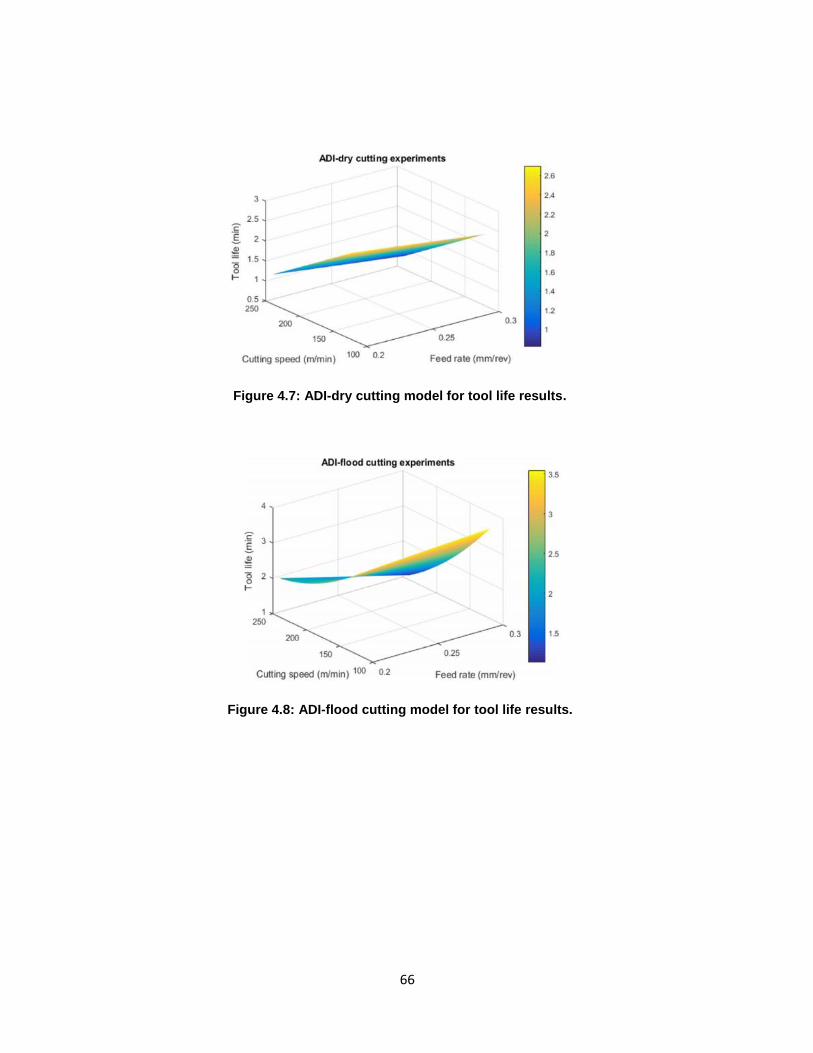
66
66
Figure 4.7: ADI-dry cutting model for tool life results.
Figure 4.8: ADI-flood cutting model for tool life results.
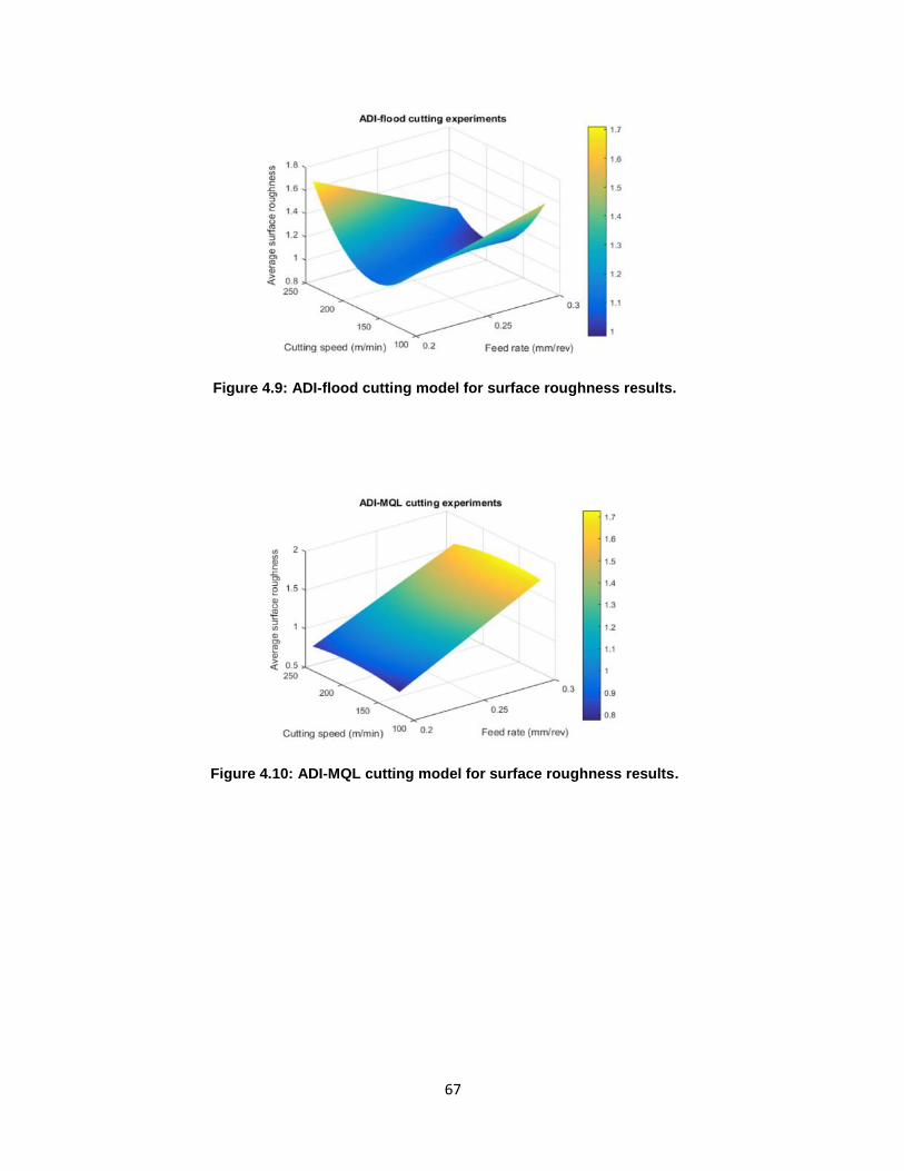
67
67
Figure 4.9: ADI-flood cutting model for surface roughness results.
Figure 4.10: ADI-MQL cutting model for surface roughness results.
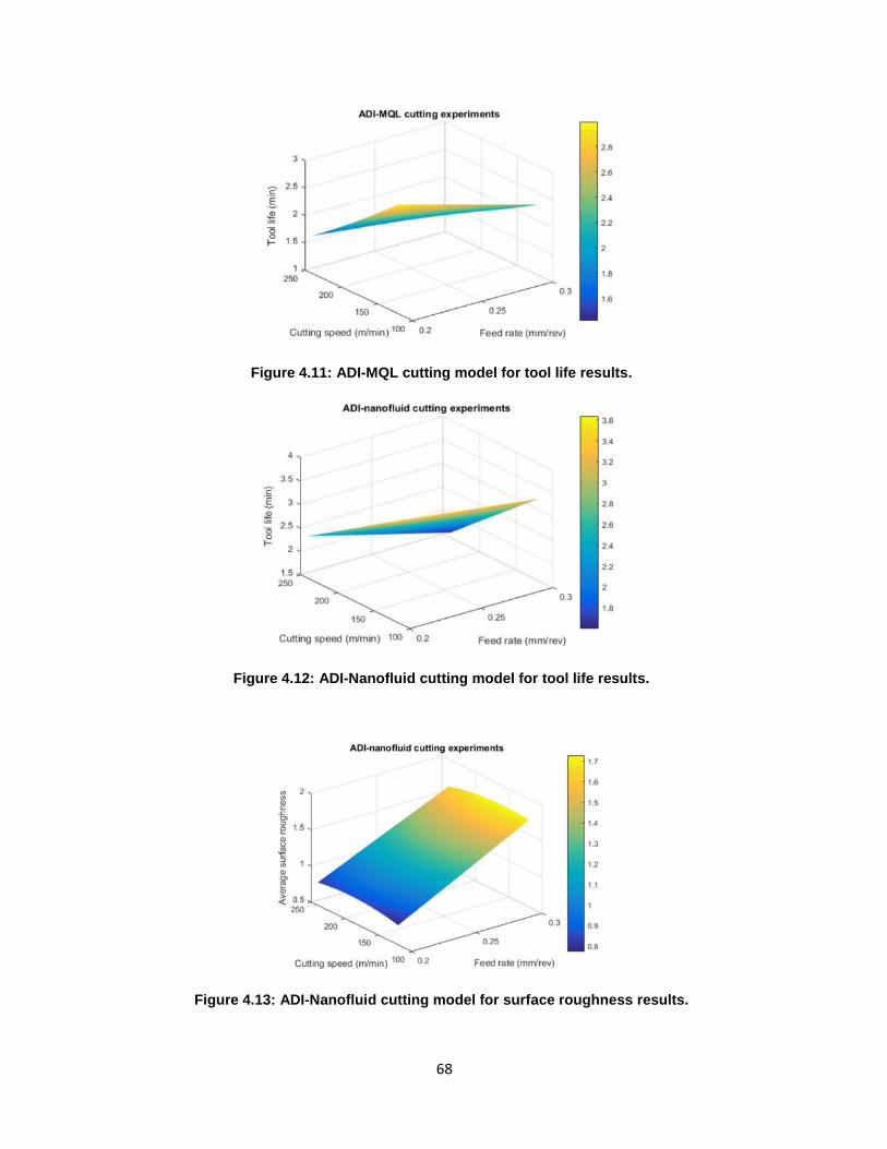
68
68
Figure 4.11: ADI-MQL cutting model for tool life results.
Figure 4.12: ADI-Nanofluid cutting model for tool life results.
Figure 4.13: ADI-Nanofluid cutting model for surface roughness results.
69
69
4.1.2.4 Wear Mechanisms Analysis
Understanding the tool wear mechanisms is important for optimization of the machining process.
From a microstructure perspective, the austenite phase in ADI is thermally stable due to its rich
carbon content. It can undergo a strain-induced transformation when the ADI is locally subjected
to stress; producing sphere particles of hard martensite which enhances tool wear [119]. All SEM
images of worn phases were captured at the end of the cutting tests.
The scanning electron microscope (SEM) images visibly show that the flank wear is the dominated
tool wear. Based on the literature [148, 149] the flank wear is essentially caused by abrasion, where
the hard particles of the workpiece rub against the tool surface. Furthermore, during chip
deformation, particles are pulled out from the contact region of the cutting tool and are taken away
by the flowing chips. This act is responsible for tool flank wear and results in shorter tool life. This
research evaluated the tool wear at the cutting speed of 120 m/ min and feed of 0.2 and 0.3 mm/rev
for different coolant methods. The results showed that the dominant tool wear observation was the
abrasion wear. It was also found that carbon and magnesium particles stacked on the flank face
are most likely due to diffusion wear as can be seen from the energy dispersive X-ray spectroscopy
(EDS) image in Figure 4.14.
70
70
Figure 4.14: EDS image for diffusion on the tool at dry machining f=0.2 mm/rev and V=120
m/min.
Generally, in all coolant strategies, a few spots of work material adhesion were observed on the
insert flank face, which can be attributed to a high cutting temperature at interface zone and the
chemical reaction of workpiece materials. Figure 4.15(a) presents the cutting edge under dry
machining at a cutting speed of 120 m/ min and feed of 0.2 mm/rev. It can be observed that
adhesion wear with a relatively large abrasion wear appeared along the flank face (red circle). In
the case of flood coolant strategy (Figure 4.15 (b)), according to SEM observations, less extent of
abrasion occurred. An amount of chipping (yellow) was also marked on the cutting edge. As
presented previously in Figure 4.2, when using the flood strategy, the cutting tool has longer life
than when using dry condition; however, it appears more severely damaged than dry in SEM
images due to the oxidation, external black layer, resulting from flood coolant Figures 4.15(b) and
4.16 (b).
71
71
Figure 4.15: SEM images of inserts after machining at V=120 m/min and f=0.2 mm/rev under
different coolant strategies.
The most important SEM observation of the flooding strategy is the appearance of thermal damage.
As a chemical reaction wear, thermal damage occurs when chemical compound are formed by
reaction of the cutting tool material with the workpiece material at high temperatures in the
presence of oxygen [150]. As shown in Figure 4.15(b), oxidation wear, which appears as a dark
area, was marked on the extremity of the tool edge (chip/tool contact region). An oxide layer can
act as a barrier against wear at the tool surface; however, it can also accelerate the wear rate.
Usually, during the machining process, the air is available in the chip/tool interface area. The
presence of air, water (in flood coolant), and high temperature was most likely producing the
oxidation wear. Moreover, as seen in Figure 4.15(c), the vegetable oil MQL yielded relatively
72
72
small abrasion, which seen within the red circle. This could be attributed to the lubricant conditions
(i.e., forming a fine mist surrounded with a base cutting fluid film) where the vegetable oil reduces
the rubbing effect between the hard particles and tool surface, generating less friction and less heat.
The main purpose of dispersed gamma-Al2O3 nanoparticles into MQL vegetable oil is to enhance
the thermal conductivity and heat transfer coefficient of the coolant. Therefore, in the case of
nanofluid coolant (Figure 4.15(d)), less abrasion wear was observed, which is labeled by a red
circle. These results indicate that dispersion of gamma- Al2O3 nanoparticles into vegetable oil
improved the performance of the MQL coolant. Furthermore, Figure 4.16 (a) shows the insert
cutting edge with abrasive and adhesive wear after dry machining at cutting speed of 120 m/min
and feed of 0.3 mm/rev.
A clear chipping was observed in the case of flood coolant as described in Figure 4.16 (b), which
could cause a tool failure. The oxidation wear was also observed in the flood strategy at a feed rate
of 0.3 mm/rev. From Figure 4.16 (b), it can be seen that a large thermal damage was located very
close to the cutting tool edge. As mentioned previously, the presence of oxygen and high
temperatures could cause this type of wear mechanism [156]. In the case of MQL, a small chipping
was detected as seen in Figure 4.16 (c). Meanwhile, the nanofluid cooling yielded less abrasion
wears as shown in Figure 4.16 (d). Ultimately, when machining ADI at cutting speed of 120 m/min
and feed of 0.3 mm/ rev, the extent of flank wear was slightly increased (9–13%) compared to feed
of 0.2 mm/rev, and the amount of chipping in the flood method was visibly observed. Increasing
the feed rate value mainly leaded to increase the induced generated heat, thus resulting into quick
thermal softening and rapid cutting edge wear.
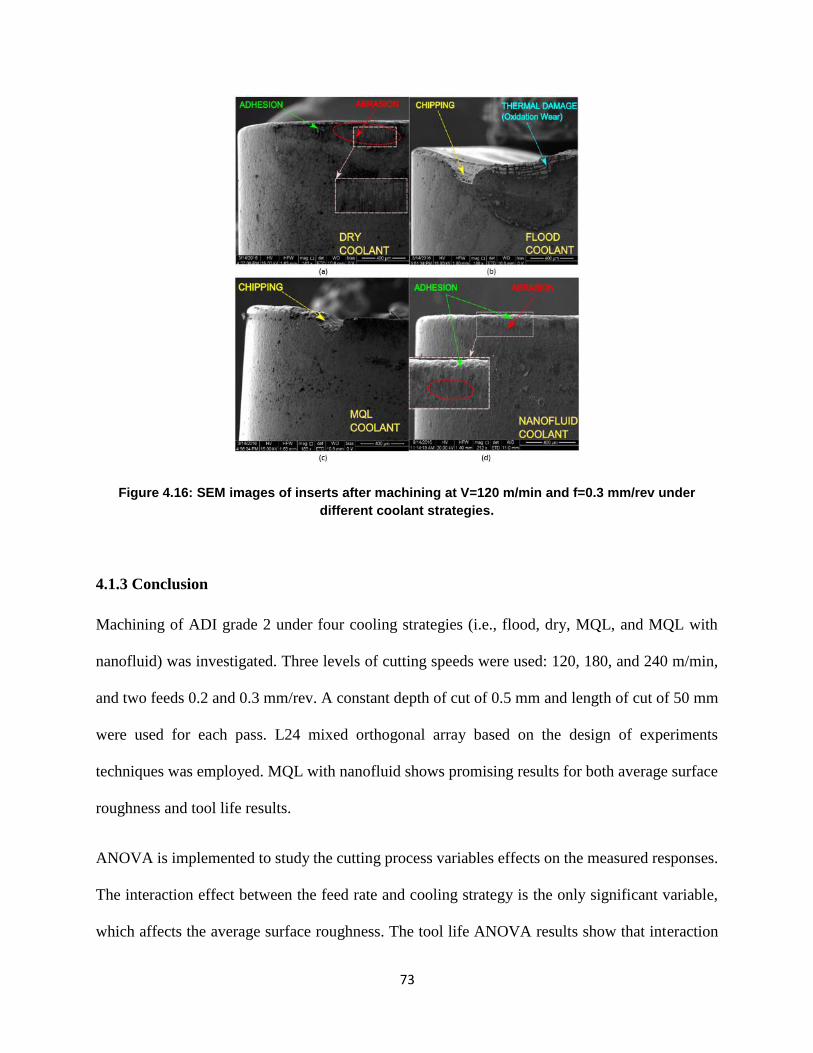
73
73
Figure 4.16: SEM images of inserts after machining at V=120 m/min and f=0.3 mm/rev under
different coolant strategies.
4.1.3 Conclusion
Machining of ADI grade 2 under four cooling strategies (i.e., flood, dry, MQL, and MQL with
nanofluid) was investigated. Three levels of cutting speeds were used: 120, 180, and 240 m/min,
and two feeds 0.2 and 0.3 mm/rev. A constant depth of cut of 0.5 mm and length of cut of 50 mm
were used for each pass. L24 mixed orthogonal array based on the design of experiments
techniques was employed. MQL with nanofluid shows promising results for both average surface
roughness and tool life results.
ANOVA is implemented to study the cutting process variables effects on the measured responses.
The interaction effect between the feed rate and cooling strategy is the only significant variable,
which affects the average surface roughness. The tool life ANOVA results show that interaction
74
74
effect between the cutting speed and cooling strategy is the only significant variable. The RSM
technique was employed to develop mathematical models for tool life and average surface for each
cooling strategy and acceptable models accuracies are observed. Regarding the tool wear
mechanisms analysis, the SEM examination revealed that abrasive and adhesive wear mechanisms
are dominant modes of tool wear when machining ADI at different cutting parameters, which can
be attributed to the hardness and chemical reaction of ADI. Due to a presence of air and elevated
temperature at the cutting zone, oxidation wear is noticed when using the flood coolant. Among
the four coolant strategies, the nanofluid provided better results at different cutting parameters in
terms of tool life and surface quality. The performance of MQL vegetable oil is improved after
dispersing 4% gamma- Al2O3 nanoparticles, hence, increasing its thermal conductivity is observed.
Also, it can be concluded that using nanofluids can reduce the induced friction at the cutting zone,
and consequently that could lead to a significant reduction in the cutting forces. The enhancement
in lubricity of nanofluids can be attributed to effect of ball bearing, tribo-film formation, mending,
and polishing effects. The better surface obtained by using nanofluid is probably due to the more
effective lubrication and cooling of the tool/workpiece interface and wettability of work material.
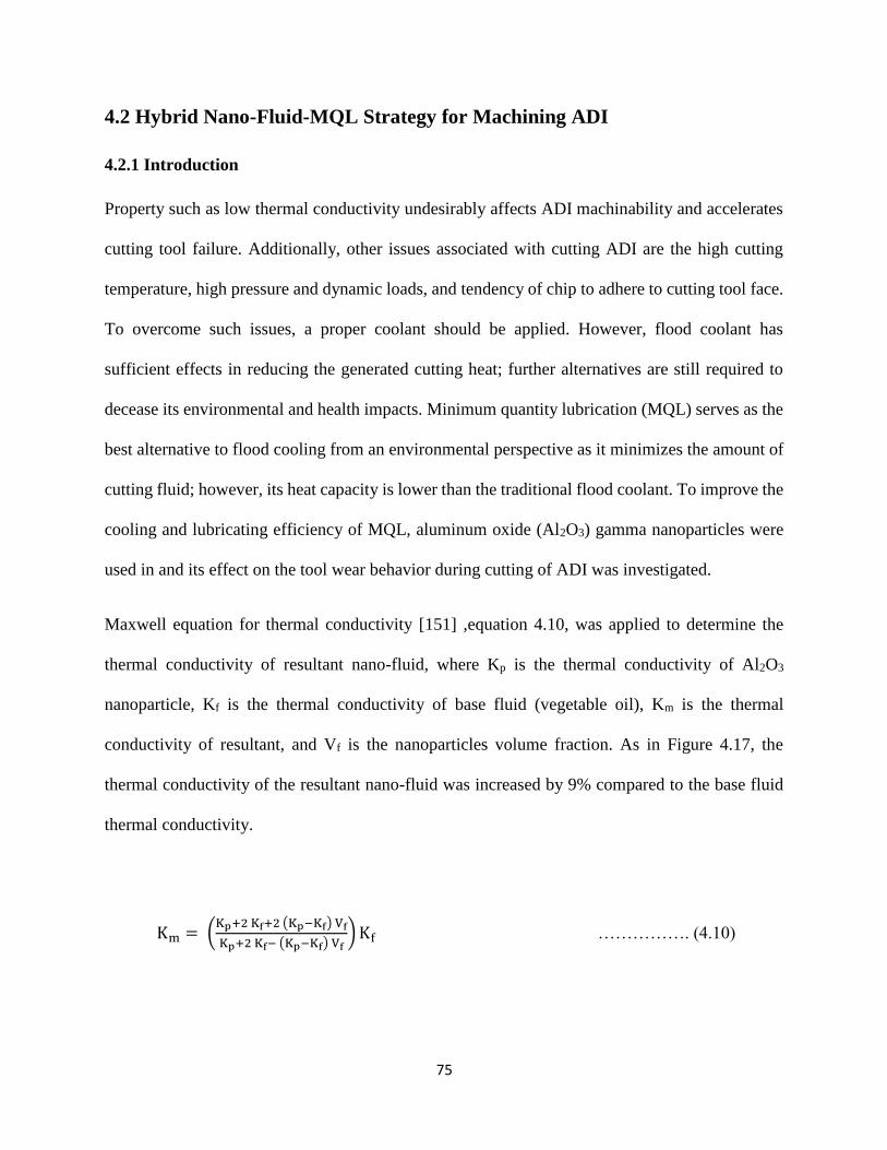
75
75
4.2 Hybrid Nano-Fluid-MQL Strategy for Machining ADI
4.2.1 Introduction
Property such as low thermal conductivity undesirably affects ADI machinability and accelerates
cutting tool failure. Additionally, other issues associated with cutting ADI are the high cutting
temperature, high pressure and dynamic loads, and tendency of chip to adhere to cutting tool face.
To overcome such issues, a proper coolant should be applied. However, flood coolant has
sufficient effects in reducing the generated cutting heat; further alternatives are still required to
decease its environmental and health impacts. Minimum quantity lubrication (MQL) serves as the
best alternative to flood cooling from an environmental perspective as it minimizes the amount of
cutting fluid; however, its heat capacity is lower than the traditional flood coolant. To improve the
cooling and lubricating efficiency of MQL, aluminum oxide (Al2O3) gamma nanoparticles were
used in and its effect on the tool wear behavior during cutting of ADI was investigated.
Maxwell equation for thermal conductivity [151] ,equation 4.10, was applied to determine the
thermal conductivity of resultant nano-fluid, where Kp is the thermal conductivity of Al2O3
nanoparticle, Kf is the thermal conductivity of base fluid (vegetable oil), Km is the thermal
conductivity of resultant, and Vf is the nanoparticles volume fraction. As in Figure 4.17, the
thermal conductivity of the resultant nano-fluid was increased by 9% compared to the base fluid
thermal conductivity.
Km = (Kp+2 Kf+2 (Kp−Kf) Vf
Kp+2 Kf− (Kp−Kf) Vf) Kf ……………. (4.10)
76
76
In the current study, three design parameters were studied (i.e. cutting feed, speed, and added nano-
additives percentage). Table 4.6 shows the design parameters, their corresponding levels, and tests
performed. The MQL method has become the best alternative coolant in different machining
processes because of the environmental concerns and excessive usage of cutting fluid in flood
coolant method. In order to reduce any environmental concern of applying MQL nano-additives,
a standard procedure was implemented. During the experimentation stage, certain safety rules were
followed to keep a specific health and safety level in the machine-shop to avoid any health hazard
to the machine operator [152].
Figure 4.17: Thermal conductivity results (Al2O3 nanofluid vs. vegetable oil).
4.2.2 Results and Discussions
4.2.2.1 Tool Wear
In this study, maximum flank wear (VB) of 0.4 mm was used as the tool life criteria. Figure 4.18
presents the tool wear progress versus the total cutting length. This work revealed that the Al2O3-
nanofluid provided better results compared to regular MQL. On one hand, the lowest flank wear
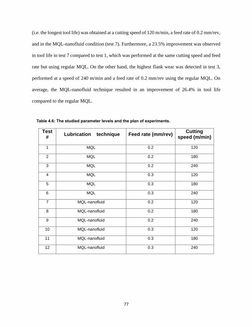
77
77
(i.e. the longest tool life) was obtained at a cutting speed of 120 m/min, a feed rate of 0.2 mm/rev,
and in the MQL-nanofluid condition (test 7). Furthermore, a 23.5% improvement was observed
in tool life in test 7 compared to test 1, which was performed at the same cutting speed and feed
rate but using regular MQL. On the other hand, the highest flank wear was detected in test 3,
performed at a speed of 240 m/min and a feed rate of 0.2 mm/rev using the regular MQL. On
average, the MQL-nanofluid technique resulted in an improvement of 26.4% in tool life
compared to the regular MQL.
Table 4.6: The studied parameter levels and the plan of experiments.
Test #
Lubrication technique Feed rate (mm/rev) Cutting
speed (m/min)
1 MQL 0.2 120
2 MQL 0.2 180
3 MQL 0.2 240
4 MQL 0.3 120
5 MQL 0.3 180
6 MQL 0.3 240
7 MQL-nanofluid 0.2 120
8 MQL-nanofluid 0.2 180
9 MQL-nanofluid 0.2 240
10 MQL-nanofluid 0.3 120
11 MQL-nanofluid 0.3 180
12 MQL-nanofluid 0.3 240
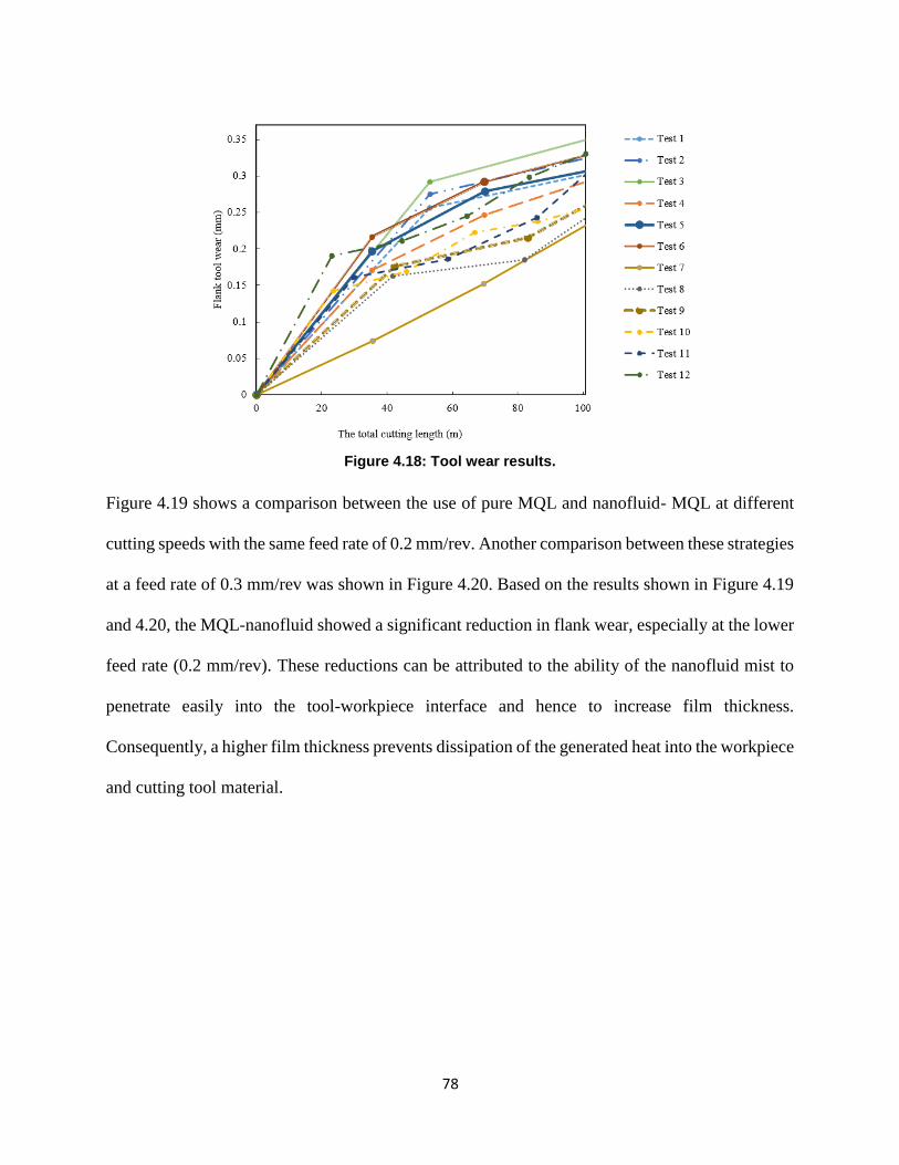
78
78
Figure 4.18: Tool wear results.
Figure 4.19 shows a comparison between the use of pure MQL and nanofluid- MQL at different
cutting speeds with the same feed rate of 0.2 mm/rev. Another comparison between these strategies
at a feed rate of 0.3 mm/rev was shown in Figure 4.20. Based on the results shown in Figure 4.19
and 4.20, the MQL-nanofluid showed a significant reduction in flank wear, especially at the lower
feed rate (0.2 mm/rev). These reductions can be attributed to the ability of the nanofluid mist to
penetrate easily into the tool-workpiece interface and hence to increase film thickness.
Consequently, a higher film thickness prevents dissipation of the generated heat into the workpiece
and cutting tool material.
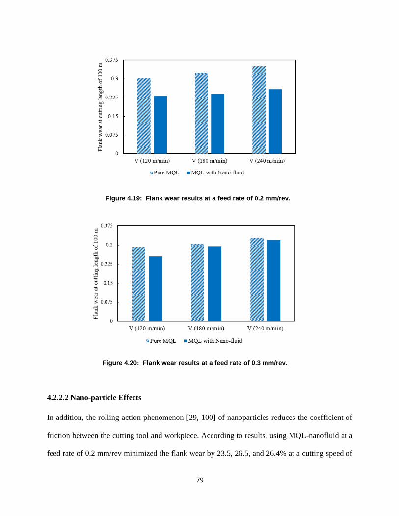
79
79
Figure 4.19: Flank wear results at a feed rate of 0.2 mm/rev.
Figure 4.20: Flank wear results at a feed rate of 0.3 mm/rev.
4.2.2.2 Nano-particle Effects
In addition, the rolling action phenomenon [29, 100] of nanoparticles reduces the coefficient of
friction between the cutting tool and workpiece. According to results, using MQL-nanofluid at a
feed rate of 0.2 mm/rev minimized the flank wear by 23.5, 26.5, and 26.4% at a cutting speed of
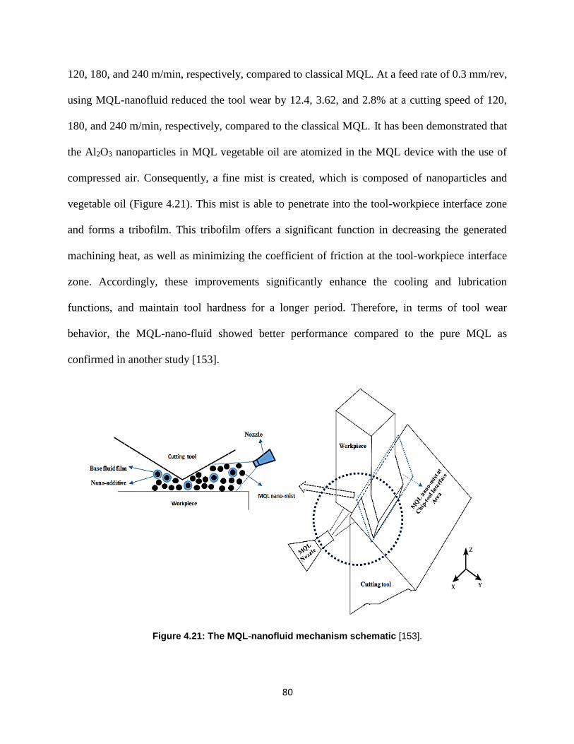
80
80
120, 180, and 240 m/min, respectively, compared to classical MQL. At a feed rate of 0.3 mm/rev,
using MQL-nanofluid reduced the tool wear by 12.4, 3.62, and 2.8% at a cutting speed of 120,
180, and 240 m/min, respectively, compared to the classical MQL. It has been demonstrated that
the Al2O3 nanoparticles in MQL vegetable oil are atomized in the MQL device with the use of
compressed air. Consequently, a fine mist is created, which is composed of nanoparticles and
vegetable oil (Figure 4.21). This mist is able to penetrate into the tool-workpiece interface zone
and forms a tribofilm. This tribofilm offers a significant function in decreasing the generated
machining heat, as well as minimizing the coefficient of friction at the tool-workpiece interface
zone. Accordingly, these improvements significantly enhance the cooling and lubrication
functions, and maintain tool hardness for a longer period. Therefore, in terms of tool wear
behavior, the MQL-nano-fluid showed better performance compared to the pure MQL as
confirmed in another study [153].
Figure 4.21: The MQL-nanofluid mechanism schematic [153].
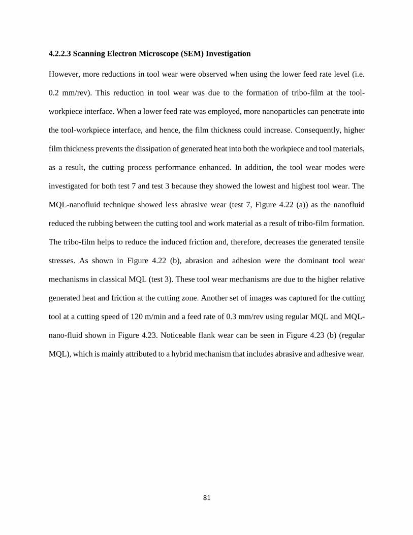
81
81
4.2.2.3 Scanning Electron Microscope (SEM) Investigation
However, more reductions in tool wear were observed when using the lower feed rate level (i.e.
0.2 mm/rev). This reduction in tool wear was due to the formation of tribo-film at the tool-
workpiece interface. When a lower feed rate was employed, more nanoparticles can penetrate into
the tool-workpiece interface, and hence, the film thickness could increase. Consequently, higher
film thickness prevents the dissipation of generated heat into both the workpiece and tool materials,
as a result, the cutting process performance enhanced. In addition, the tool wear modes were
investigated for both test 7 and test 3 because they showed the lowest and highest tool wear. The
MQL-nanofluid technique showed less abrasive wear (test 7, Figure 4.22 (a)) as the nanofluid
reduced the rubbing between the cutting tool and work material as a result of tribo-film formation.
The tribo-film helps to reduce the induced friction and, therefore, decreases the generated tensile
stresses. As shown in Figure 4.22 (b), abrasion and adhesion were the dominant tool wear
mechanisms in classical MQL (test 3). These tool wear mechanisms are due to the higher relative
generated heat and friction at the cutting zone. Another set of images was captured for the cutting
tool at a cutting speed of 120 m/min and a feed rate of 0.3 mm/rev using regular MQL and MQL-
nano-fluid shown in Figure 4.23. Noticeable flank wear can be seen in Figure 4.23 (b) (regular
MQL), which is mainly attributed to a hybrid mechanism that includes abrasive and adhesive wear.
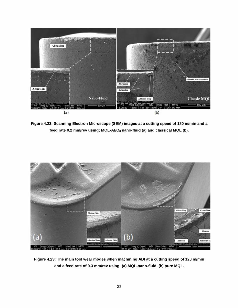
82
82
Figure 4.22: Scanning Electron Microscope (SEM) images at a cutting speed of 180 m/min and a
feed rate 0.2 mm/rev using; MQL-Al2O3 nano-fluid (a) and classical MQL (b).
Figure 4.23: The main tool wear modes when machining ADI at a cutting speed of 120 m/min
and a feed rate of 0.3 mm/rev using: (a) MQL-nano-fluid, (b) pure MQL.
83
83
In general, for both MQL and nano-fluid techniques, the adhesion wear was the most significant
tool wear mechanism; however, it can be noted that using MQL-Al2O3-nano-fluid decreased the
flank wear severity in comparison with the classic MQL method (Figure 4.23 (a)). Also, as shown
in Figure 4.23 (b), the crater wear formation was reduced using the nano-fluid coolant.
Furthermore, a cleaner rake face and more a stable cutting edge were obtained on cutting tool when
applying nanofluid coolant. Away from the crater wear investigations, similar tool wear modes
were noticed when machining with pure MQL and MQL-nano-fluid; however, different wear rates
and wear levels were observed. Also, the molten chips and a built-up-edge layer (BUL) were
detected when machining with pure MQL (Figure 4.23 (7)) because of the high contact between
the workpiece and cutting tool under sufficient pressure and temperature. The improvement in
cutting tool conditions when using nano-fluid coolant is mainly due to the enhancement in thermal
conductivity of the nano-fluid coolant which decreases the generated cutting temperature and
reduces the tool wear severity accordingly. Many studies [154–160] revealed that the nano-fluids
have shown effective results on the cutting performance characteristics through different cutting
operations such as milling, turning, and grinding. The suspended nano-additves in the base fluid
produce impressive enhancement in the thermal conductivity and convective heat transfer
coefficient, and consequently a substantial huge amount of generated heat could be carried out
from the cutting zone. Furthermore, the tool wear rate was reduced by using nanofluid-MQL due
to the frictional behavior enhancement as the nano-additives work as spacers in the tool-workpeice
interface area and reduce the induced coefficient of friction. Accordingly, the cutting forces,
friction, tool wear rate, and surface roughness could be minimized.

84
84
4.2.2.4 Nanofluid-MQL Mechanism
In order to gain further improvements on cutting performance using MQL nano-fluids, an
understanding of the mechanisms is highly important. The MQL nano-fluid mechanism can be
summarized as follows (Figure 4.21):
1. By applying a source of compressed air, the nano-cutting fluid is atomized into the
MQL nozzle, resulting in a very fine mist.
2. Thus, the droplets of the nano-cutting-fluid are formed on the workpiece and cutting
tool surfaces and a tribo-film also formed which significantly enhances the
tribological characteristics and reduces the induced friction.
3. The increasing in nano-additive concentration increases the number of nano-
additives at the tool-workpiece interface; these nano-additives perform a vital role as
spacers, reducing the contact between the tool and workpiece.
4. Due to the high compression with increasing the nano-additives concertation, the
nano-additive shape is changed and the shearing is more intense. Some of the nano-
additives in cutting zone are ejected away from tool-workpiece interface by other
additives being sprayed from the nozzle.
5. Therefore, due to the extreme pressure in the naofluid-MQL and existence of a gap
at tool–workpiece interface; nano-additives provide high contact resistance which
helps in forming a chemical reaction film on the workpiece surface. The increase in
nano-additive concentration increase the thickness of this thin protective film on the
machined surface as has been discussed in another study [29, 161].
To sum up, using Al2O3 nano-fluids with MQL showed significant improvements during cutting
ADI. It should be stated that MQL-nano-fluids technique helps in enhancing the interface bonding
85
85
between the tool and workpiece, which generally improves the machinability performance.
Another function of applying MQL-nano-fluids is to dissipate the generated heat, and therefore
the tool wear behavior could be enhanced. Also, the resultant nano-mist works as spacers to reduce
the induced coefficient of friction. Based on the previous considerations, MQL-nano-fluid
achieves a balance between accomplishing a sustainable environment, and enhancing the
machining performance.
Finally, Nanofluid- MQL approach has been successfully introduced as an effective interactive
approach for cooling and lubrication when machining ADI. Applying such an interactive approach
showed promising results in terms of improving the tool wear behavior with maintaining a
sustainable machining environment.
4.2.3 Conclusion
In this study, MQL-nanofluid technique offered significant improvement in tool wear behavior
during cutting of ADI in comparison with the classical MQL. The combination of MQL-nanofluid
at a cutting speed of 120 m/min and a feed rate of 0.2 mm/rev showed the best tool life, while tests
at a higher speed of 240 m/min and a feed rate of 0.2 mm/rev using classical MQL provided the
worst tool wear value. Due to the improved convection, wettability, and conduction characteristics
of the proposed nanofluid, the tool wear was significantly reduced because of the tribo-film
formation along the tool-workpiece interface zone. Also, the nano-fluid mist served as spacers to
limit the induced rubbing between the tool and workpiece, and hence the resultant friction was
reduced. In addition, more improvements in the tool wear behavior were noticed at the lower feed
rate level (0.2 mm/rev). The nano-fluid mist appeared to easily settle on the tool and workpiece
surfaces when the lower feed rate was employed, and therefore the tribo-film thickness increased
and the lubrication effect significantly improved (i.e. protective film mechanism).Moreover,
86
86
similar tool wear modes (i.e. flank and crater wears) were observed when machining ADI using
pure MQL and nanofluid-MQL; however, using nanofluid-MQL, lower wear rates and wear levels
were occurred due to the significant heat and tribological characteristics of the resultant nano-fluid.
Thus, MQL-nano-fluid approach has been successfully introduced as an effective interactive
approach for cooling and lubrication when machining ADI. Finally, more investigations need to
be performed in order to understand the effects of the nano-additives size and concentration on the
coefficient friction and the induced tool wear.
87
87
4.3 - Application of MQL with Nano-Fluids during Machining of Ti-6Al-4V
Alloy: Experimental Investigation and Analysis
4.3.1 Introduction
The cutting fluids are extensive used in almost all kind of manufacturing industries. Apart of work-
tool interface cooling they also perform the lubrication regime. Therefore, they account for
generating good working conditions at the tool work interface. It also leads to the enhancement of
several properties and process parameters like surface topology or cutting forces. On the contrary,
these fluids have some detrimental effects on both human health as well as on the environment.
The majority of such fluids contains potentially harmful chemicals. The recycling costs of such
fluids are very high and their disposal also poses several issues. Operators handling such chemicals
over a longer period of time are bound to suffer from skin or lung related diseases. The past two
decades have witnessed a collective research all over the globe for developing dry or near dry
machining processes to bypass the hazardous chemicals and their use. Due to its simple application
and eco-friendly features, MQL has emerged as one of the best solutions to tackles this challenge.
It has been widely used for most of the machining operations ranging from turning to grinding.
The results obtained after investigating these process clearly indicate the benefits of the MQL
process while machining some different materials such as steel, aluminum, Inconel, and titanium.
Cutting fluids are mainly used to reduce the cutting temperature and friction, and to wash away
chips from the cutting zone during machining operation. When cutting difficult-to-cut materials,
the high amount of heat generated significantly affects the tool life. Therefore, much research has
been attempted to produce cutting fluids with superior tribological and thermal properties linked
with the operator health and environment impacts. Minimum quantity lubrication (MQL) is an
environmentally friendly coolant strategy, but it has leak in cooling capacity.
88
88
Many applications in the field of automotive and aeronautical industries utilize the difficult-to-cut
materials due to their effective properties which are namely high corrosion resistance and better
strength-to-weight ratio [162]. On the other hand, there are characteristics including low thermal
conductivity and high hardness, which have negative effect of the machined surface roughness and
tool life. An understanding of the influence of different machining design variables (e.g., cutting
velocity, tool geometry, coolant strategy, feed rate, depth of cut), has a significant act in improving
machinability, productivity, and reducing the total machining cost. Several studies have been
conducted with an aim to specify the optimal machining variables and select the better coolant
strategy as machining of hard-to-cut materials is still facing different problems particularly,
ceramics, titanium alloys, polymers, nickel-based alloys, composite based materials, and hardened
steels [163-167]. However, the unique characteristics of nickel based alloys, such as, high thermal
fatigue resistance, high erosion resistance, and high melting temperature; the disposal of the
generated heat during the machining is not suitable due to the low heat conductivity of these alloys
[168, 169]. The increase of the machining generated heat over the critical limit, which is 650○C,
leads to negative effects on the machined workpiece and the tool [170]. In general, improper tool
wear behavior and surface integrity are correlated with the machining of nickel alloys [171, 172].
The usage of cutting fluids during machining is mainly to take out the cutting generated heat.
Despite the ability of flood cooling to eliminate machinability problems, there are governmental
restrictions to use it to reduce its crucial impacts on the health and environment. Alternatively, the
use of minimum quantity lubricant (MQL) reduces the cutting fluid quantity during machining.
During machining difficult-to-cut materials, MQL is not a proper alternative of the flood coolant.
To enhance the wettability and fluid thermal aspects, MQL nano-fluid approach has been used [83,
173]. The nano-additives such as aluminum oxide (Al2O3) gamma nano-particles have superior
89
89
cooling and lubrication properties. The effect of the nano-fluids technology on the performance of
machining processes has been studied in several articles. For example, the nano-diamond particles
were dispersed in paraffin and vegetable oils under MQL during micro drilling of aluminum 6061
[178]; aluminum oxide-based nano-fluid has been used in micro-grinding of tool steel [179];
MQL-nano-fluid with chilly CO2 gas was implemented during micro-end-milling of Ti-6Al-4V
[180]. It should be stated that MQL-nano-fluid showed promising results in enhancing the
machining performance in all above-mentioned studies. Furthermore, multi-walled carbon
nanotubes based nano-fluids with MQL showed better results in surface roughness [181] and flank
wear [182] compared to classical MQL and Al2O3 based nano-fluids during machining Ti-6Al-4V.
In addition, many attempts have focused on employing the MQL-nanofluid technique when
machining especially when machining Inconel 718 [183, 184], and austempered ductile iron (ADI)
[98, 153], and promising results have obtained in terms of tool wear, chip morphology, cutting
power, and surface quality. Despite of the previous attempts, there is a research gap in establishing
a multi-objectives model to optimize these machining outputs
In this study, to enhance the thermal conductivity and viscosity of the MQL approach,
nanoparticles were dispersed into the base fluid. Furthermore, the ANOVA analysis was
performed to investigate the effects of cutting speeds, feed rates, and nanoparticle concentrations
during the machining of a titanium Ti-Al6-V4 alloy. Aluminum Oxide (Al2O3) nanoparticles were
selected to use as nano-additives at different weight fraction concentrations (0, 2, and 4%). The
main objective of this work is to study the nanoparticle concentration effects on surface roughness,
tool life, and power consumption when machining Ti-Al6-4V alloy. Besides, a clear tribological
mechanism is presented and discussed to physically justify the nanoparticle concentration effects
on the machining performance.
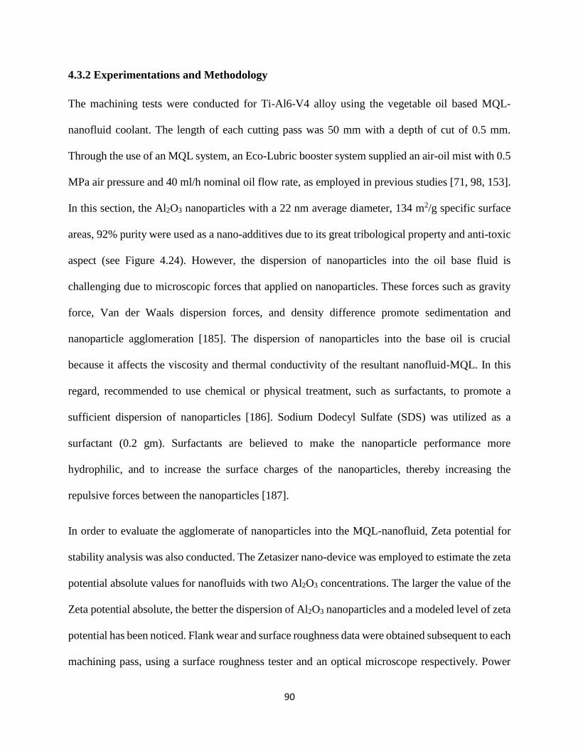
90
90
4.3.2 Experimentations and Methodology
The machining tests were conducted for Ti-Al6-V4 alloy using the vegetable oil based MQL-
nanofluid coolant. The length of each cutting pass was 50 mm with a depth of cut of 0.5 mm.
Through the use of an MQL system, an Eco-Lubric booster system supplied an air-oil mist with 0.5
MPa air pressure and 40 ml/h nominal oil flow rate, as employed in previous studies [71, 98, 153].
In this section, the Al2O3 nanoparticles with a 22 nm average diameter, 134 m2/g specific surface
areas, 92% purity were used as a nano-additives due to its great tribological property and anti-toxic
aspect (see Figure 4.24). However, the dispersion of nanoparticles into the oil base fluid is
challenging due to microscopic forces that applied on nanoparticles. These forces such as gravity
force, Van der Waals dispersion forces, and density difference promote sedimentation and
nanoparticle agglomeration [185]. The dispersion of nanoparticles into the base oil is crucial
because it affects the viscosity and thermal conductivity of the resultant nanofluid-MQL. In this
regard, recommended to use chemical or physical treatment, such as surfactants, to promote a
sufficient dispersion of nanoparticles [186]. Sodium Dodecyl Sulfate (SDS) was utilized as a
surfactant (0.2 gm). Surfactants are believed to make the nanoparticle performance more
hydrophilic, and to increase the surface charges of the nanoparticles, thereby increasing the
repulsive forces between the nanoparticles [187].
In order to evaluate the agglomerate of nanoparticles into the MQL-nanofluid, Zeta potential for
stability analysis was also conducted. The Zetasizer nano-device was employed to estimate the zeta
potential absolute values for nanofluids with two Al2O3 concentrations. The larger the value of the
Zeta potential absolute, the better the dispersion of Al2O3 nanoparticles and a modeled level of zeta
potential has been noticed. Flank wear and surface roughness data were obtained subsequent to each
machining pass, using a surface roughness tester and an optical microscope respectively. Power
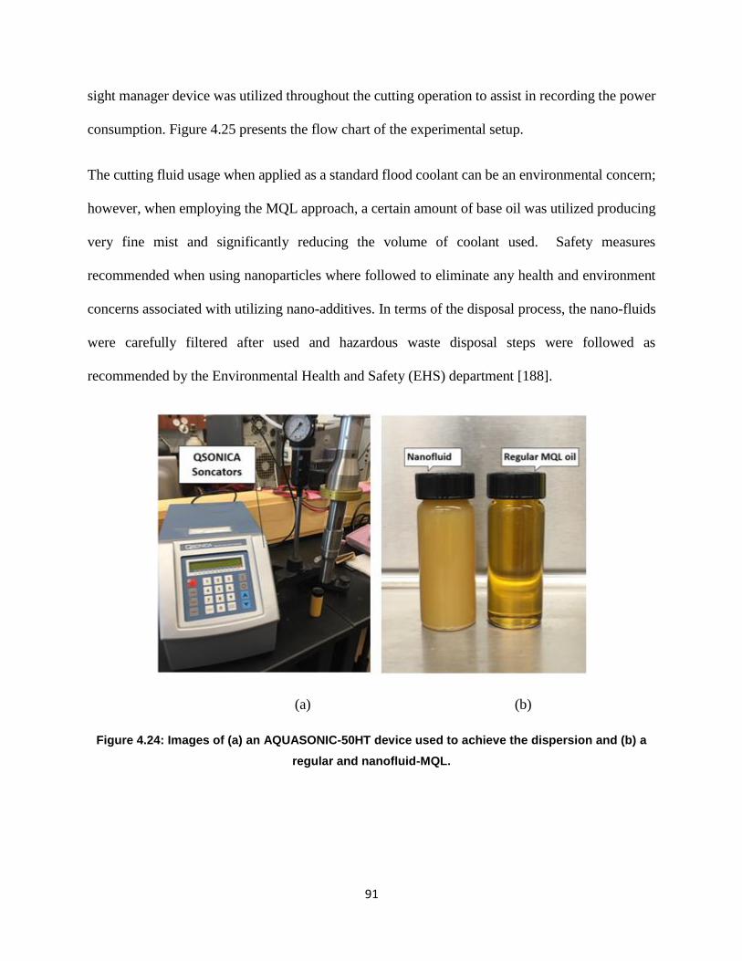
91
91
sight manager device was utilized throughout the cutting operation to assist in recording the power
consumption. Figure 4.25 presents the flow chart of the experimental setup.
The cutting fluid usage when applied as a standard flood coolant can be an environmental concern;
however, when employing the MQL approach, a certain amount of base oil was utilized producing
very fine mist and significantly reducing the volume of coolant used. Safety measures
recommended when using nanoparticles where followed to eliminate any health and environment
concerns associated with utilizing nano-additives. In terms of the disposal process, the nano-fluids
were carefully filtered after used and hazardous waste disposal steps were followed as
recommended by the Environmental Health and Safety (EHS) department [188].
(a) (b)
Figure 4.24: Images of (a) an AQUASONIC-50HT device used to achieve the dispersion and (b) a
regular and nanofluid-MQL.
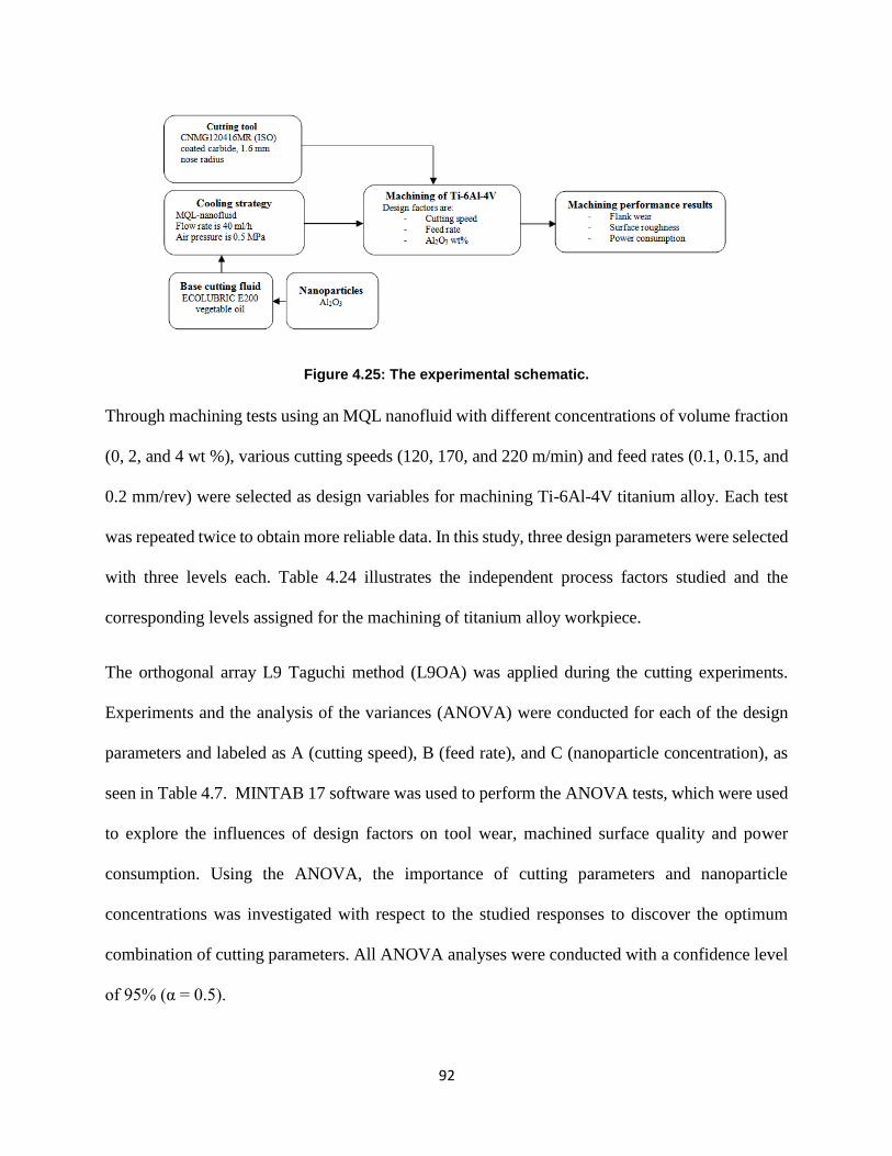
92
92
Figure 4.25: The experimental schematic.
Through machining tests using an MQL nanofluid with different concentrations of volume fraction
(0, 2, and 4 wt %), various cutting speeds (120, 170, and 220 m/min) and feed rates (0.1, 0.15, and
0.2 mm/rev) were selected as design variables for machining Ti-6Al-4V titanium alloy. Each test
was repeated twice to obtain more reliable data. In this study, three design parameters were selected
with three levels each. Table 4.24 illustrates the independent process factors studied and the
corresponding levels assigned for the machining of titanium alloy workpiece.
The orthogonal array L9 Taguchi method (L9OA) was applied during the cutting experiments.
Experiments and the analysis of the variances (ANOVA) were conducted for each of the design
parameters and labeled as A (cutting speed), B (feed rate), and C (nanoparticle concentration), as
seen in Table 4.7. MINTAB 17 software was used to perform the ANOVA tests, which were used
to explore the influences of design factors on tool wear, machined surface quality and power
consumption. Using the ANOVA, the importance of cutting parameters and nanoparticle
concentrations was investigated with respect to the studied responses to discover the optimum
combination of cutting parameters. All ANOVA analyses were conducted with a confidence level
of 95% (α = 0.5).
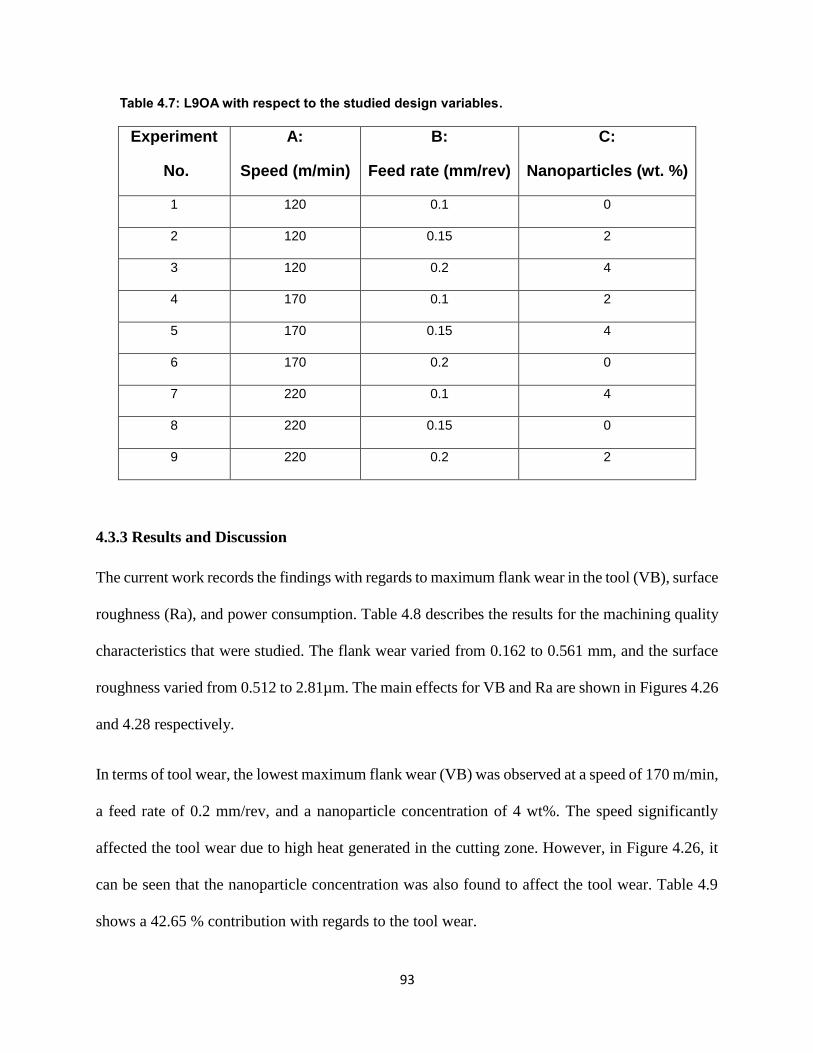
93
93
Table 4.7: L9OA with respect to the studied design variables.
Experiment
No.
A:
Speed (m/min)
B:
Feed rate (mm/rev)
C:
Nanoparticles (wt. %)
1 120 0.1 0
2 120 0.15 2
3 120 0.2 4
4 170 0.1 2
5 170 0.15 4
6 170 0.2 0
7 220 0.1 4
8 220 0.15 0
9 220 0.2 2
4.3.3 Results and Discussion
The current work records the findings with regards to maximum flank wear in the tool (VB), surface
roughness (Ra), and power consumption. Table 4.8 describes the results for the machining quality
characteristics that were studied. The flank wear varied from 0.162 to 0.561 mm, and the surface
roughness varied from 0.512 to 2.81µm. The main effects for VB and Ra are shown in Figures 4.26
and 4.28 respectively.
In terms of tool wear, the lowest maximum flank wear (VB) was observed at a speed of 170 m/min,
a feed rate of 0.2 mm/rev, and a nanoparticle concentration of 4 wt%. The speed significantly
affected the tool wear due to high heat generated in the cutting zone. However, in Figure 4.26, it
can be seen that the nanoparticle concentration was also found to affect the tool wear. Table 4.9
shows a 42.65 % contribution with regards to the tool wear.
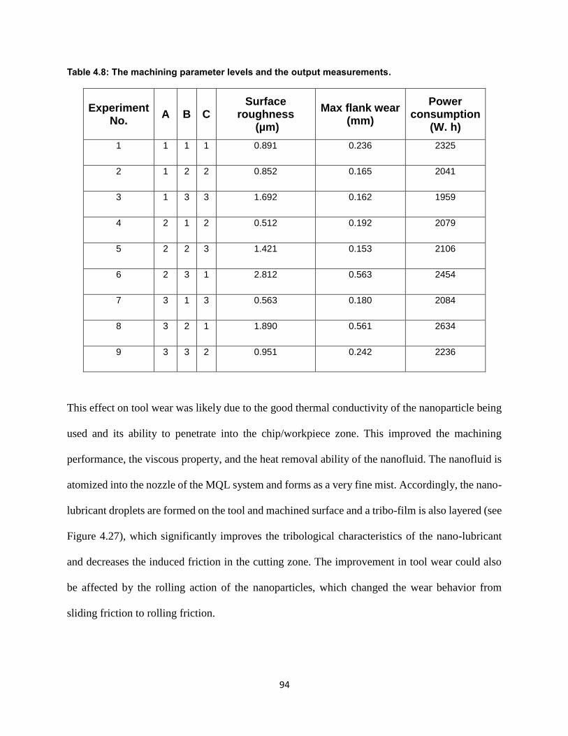
94
94
Table 4.8: The machining parameter levels and the output measurements.
Experiment No.
A B C Surface
roughness (µm)
Max flank wear (mm)
Power consumption
(W. h)
1 1 1 1 0.891 0.236 2325
2 1 2 2 0.852 0.165 2041
3 1 3 3 1.692 0.162 1959
4 2 1 2 0.512 0.192 2079
5 2 2 3 1.421 0.153 2106
6 2 3 1 2.812 0.563 2454
7 3 1 3 0.563 0.180 2084
8 3 2 1 1.890 0.561 2634
9 3 3 2 0.951 0.242 2236
This effect on tool wear was likely due to the good thermal conductivity of the nanoparticle being
used and its ability to penetrate into the chip/workpiece zone. This improved the machining
performance, the viscous property, and the heat removal ability of the nanofluid. The nanofluid is
atomized into the nozzle of the MQL system and forms as a very fine mist. Accordingly, the nano-
lubricant droplets are formed on the tool and machined surface and a tribo-film is also layered (see
Figure 4.27), which significantly improves the tribological characteristics of the nano-lubricant
and decreases the induced friction in the cutting zone. The improvement in tool wear could also
be affected by the rolling action of the nanoparticles, which changed the wear behavior from
sliding friction to rolling friction.
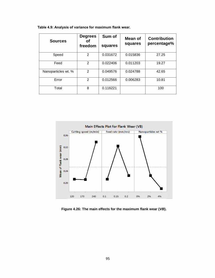
95
95
Table 4.9: Analysis of variance for maximum flank wear.
Sources Degrees
of freedom
Sum of
squares
Mean of squares
Contribution percentage%
Speed 2 0.031672 0.015836 27.25
Feed 2 0.022406 0.011203 19.27
Nanoparticles wt. % 2 0.049576 0.024788 42.65
Error 2 0.012566 0.006283 10.81
Total 8 0.116221 100
Figure 4.26: The main effects for the maximum flank wear (VB).
120 170 240 0.1 0.15 0.2 0% 2% 4%
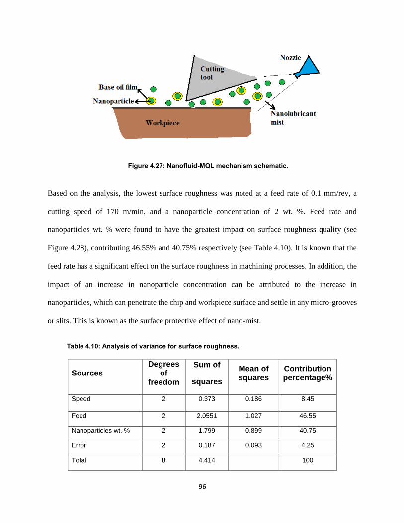
96
96
Figure 4.27: Nanofluid-MQL mechanism schematic.
Based on the analysis, the lowest surface roughness was noted at a feed rate of 0.1 mm/rev, a
cutting speed of 170 m/min, and a nanoparticle concentration of 2 wt. %. Feed rate and
nanoparticles wt. % were found to have the greatest impact on surface roughness quality (see
Figure 4.28), contributing 46.55% and 40.75% respectively (see Table 4.10). It is known that the
feed rate has a significant effect on the surface roughness in machining processes. In addition, the
impact of an increase in nanoparticle concentration can be attributed to the increase in
nanoparticles, which can penetrate the chip and workpiece surface and settle in any micro-grooves
or slits. This is known as the surface protective effect of nano-mist.
Table 4.10: Analysis of variance for surface roughness.
Sources Degrees
of freedom
Sum of
squares
Mean of squares
Contribution percentage%
Speed 2 0.373 0.186 8.45
Feed 2 2.0551 1.027 46.55
Nanoparticles wt. % 2 1.799 0.899 40.75
Error 2 0.187 0.093 4.25
Total 8 4.414 100
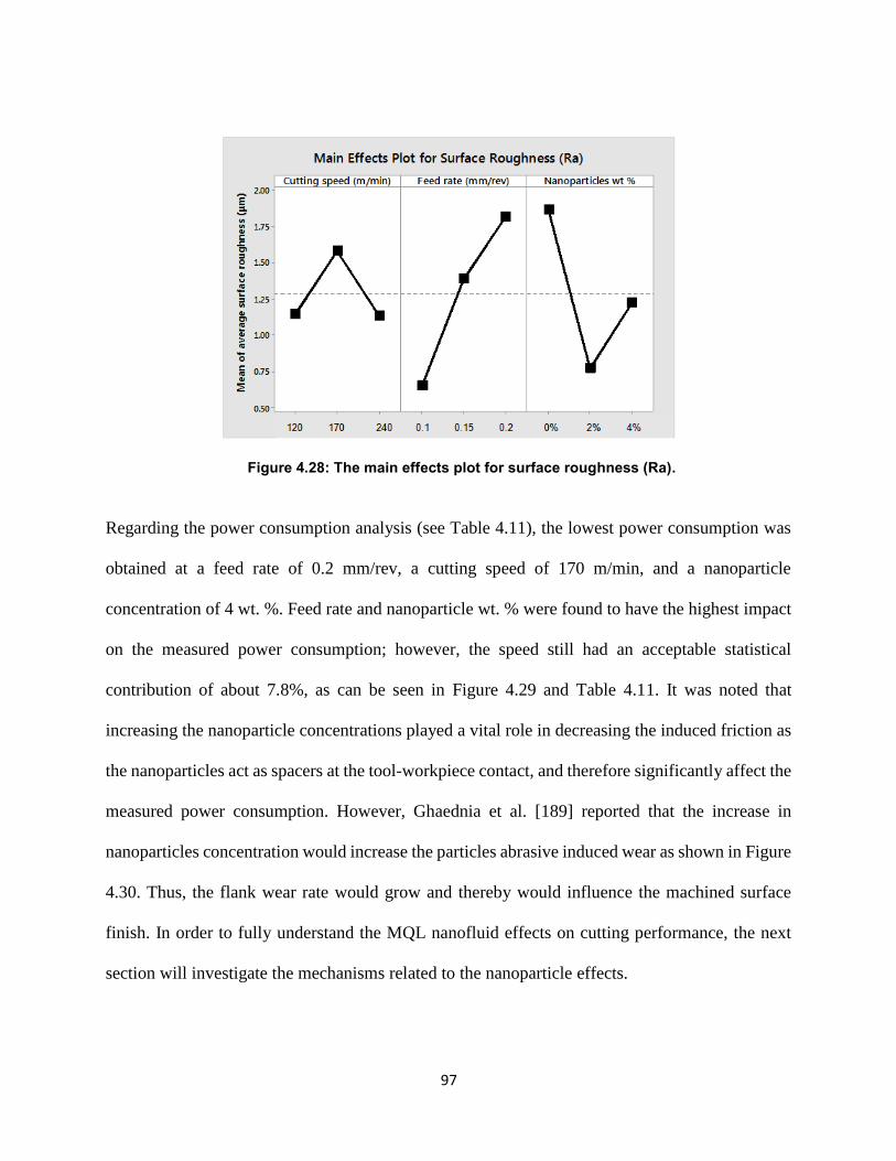
97
97
Figure 4.28: The main effects plot for surface roughness (Ra).
Regarding the power consumption analysis (see Table 4.11), the lowest power consumption was
obtained at a feed rate of 0.2 mm/rev, a cutting speed of 170 m/min, and a nanoparticle
concentration of 4 wt. %. Feed rate and nanoparticle wt. % were found to have the highest impact
on the measured power consumption; however, the speed still had an acceptable statistical
contribution of about 7.8%, as can be seen in Figure 4.29 and Table 4.11. It was noted that
increasing the nanoparticle concentrations played a vital role in decreasing the induced friction as
the nanoparticles act as spacers at the tool-workpiece contact, and therefore significantly affect the
measured power consumption. However, Ghaednia et al. [189] reported that the increase in
nanoparticles concentration would increase the particles abrasive induced wear as shown in Figure
4.30. Thus, the flank wear rate would grow and thereby would influence the machined surface
finish. In order to fully understand the MQL nanofluid effects on cutting performance, the next
section will investigate the mechanisms related to the nanoparticle effects.
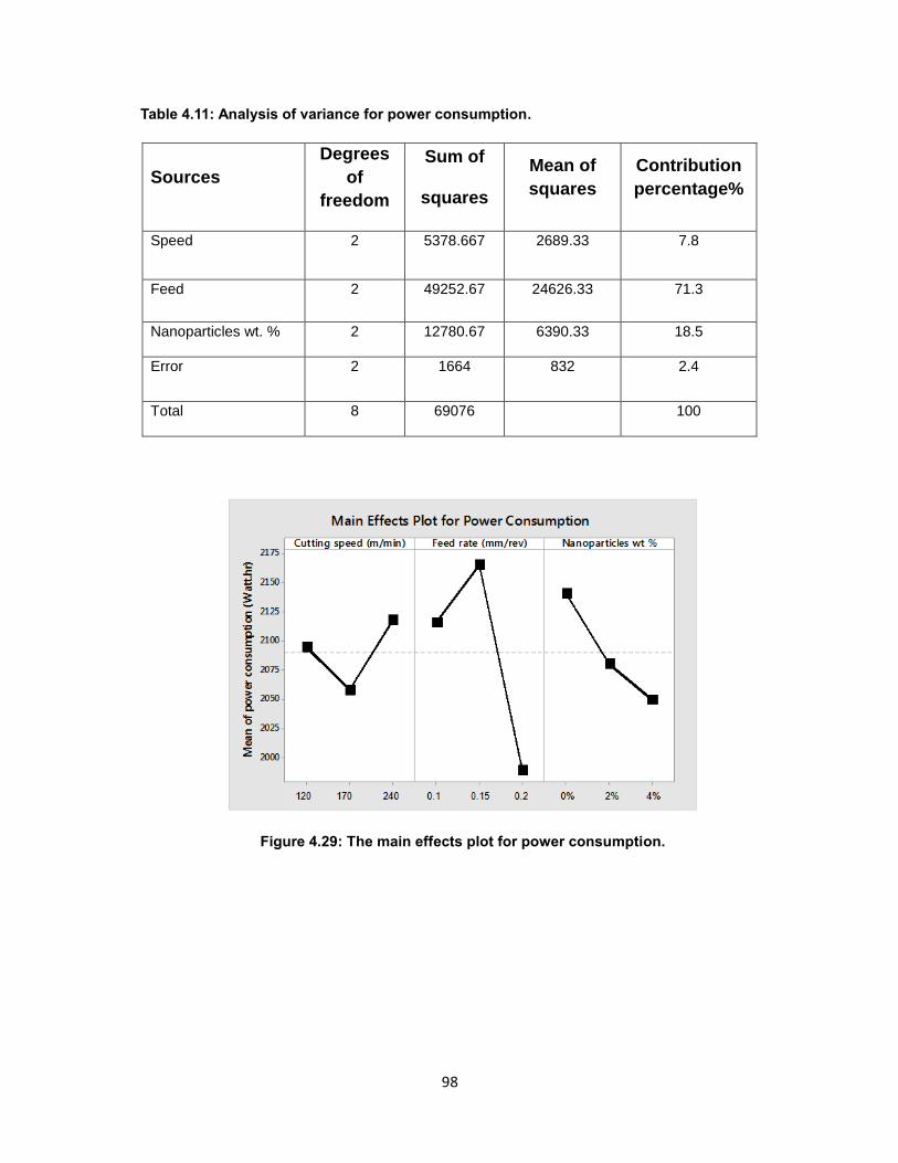
98
98
Table 4.11: Analysis of variance for power consumption.
Sources
Degrees
of
freedom
Sum of
squares
Mean of
squares
Contribution
percentage%
Speed 2 5378.667 2689.33 7.8
Feed 2 49252.67 24626.33 71.3
Nanoparticles wt. % 2 12780.67 6390.33 18.5
Error 2 1664 832 2.4
Total 8 69076 100
Figure 4.29: The main effects plot for power consumption.
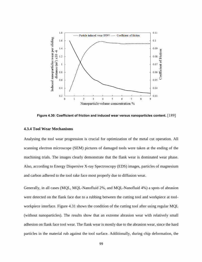
99
99
Figure 4.30: Coefficient of friction and induced wear versus nanoparticles content. [189]
4.3.4 Tool Wear Mechanisms
Analysing the tool wear progression is crucial for optimization of the metal cut operation. All
scanning electron microscope (SEM) pictures of damaged tools were taken at the ending of the
machining trials. The images clearly demonstrate that the flank wear is dominated wear phase.
Also, according to Energy Dispersive X-ray Spectroscopy (EDS) images, particles of magnesium
and carbon adhered to the tool rake face most properly due to diffusion wear.
Generally, in all cases (MQL, MQL-Nanofluid 2%, and MQL-Nanofluid 4%) a spots of abrasion
were detected on the flank face due to a rubbing between the cutting tool and workpiece at tool-
workpiece interface. Figure 4.31 shows the condition of the cutting tool after using regular MQL
(without nanoparticles). The results show that an extreme abrasion wear with relatively small
adhesion on flank face tool wear. The flank wear is mostly due to the abrasion wear, since the hard
particles in the material rub against the tool surface. Additionally, during chip deformation, the
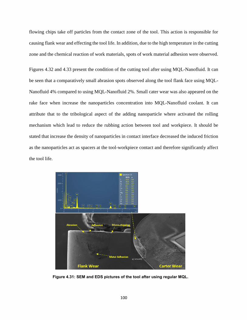
100
100
flowing chips take off particles from the contact zone of the tool. This action is responsible for
causing flank wear and effecting the tool life. In addition, due to the high temperature in the cutting
zone and the chemical reaction of work materials, spots of work material adhesion were observed.
Figures 4.32 and 4.33 present the condition of the cutting tool after using MQL-Nanofluid. It can
be seen that a comparatively small abrasion spots observed along the tool flank face using MQL-
Nanofluid 4% compared to using MQL-Nanofluid 2%. Small cater wear was also appeared on the
rake face when increase the nanoparticles concentration into MQL-Nanofluid coolant. It can
attribute that to the tribological aspect of the adding nanoparticle where activated the rolling
mechanism which lead to reduce the rubbing action between tool and workpiece. It should be
stated that increase the density of nanoparticles in contact interface decreased the induced friction
as the nanoparticles act as spacers at the tool-workpiece contact and therefore significantly affect
the tool life.
Figure 4.31: SEM and EDS pictures of the tool after using regular MQL.
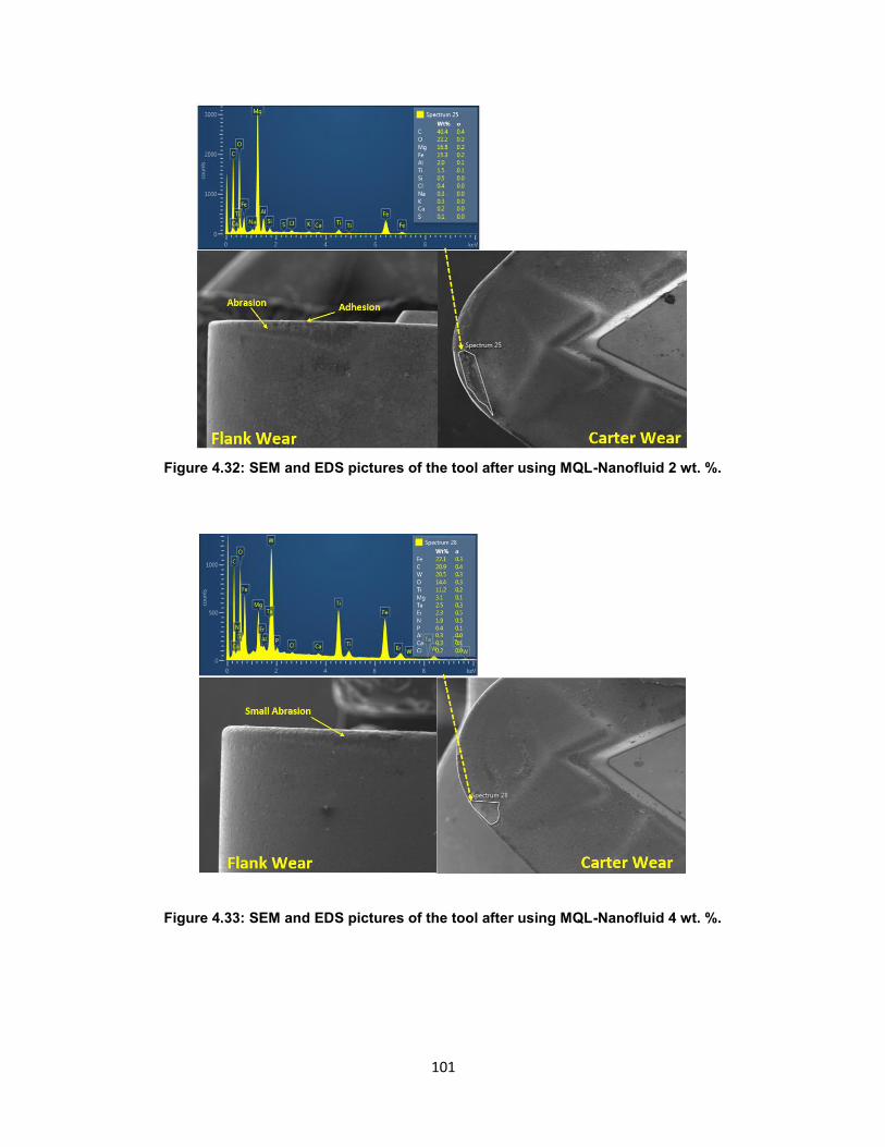
101
101
Figure 4.32: SEM and EDS pictures of the tool after using MQL-Nanofluid 2 wt. %.
Figure 4.33: SEM and EDS pictures of the tool after using MQL-Nanofluid 4 wt. %.
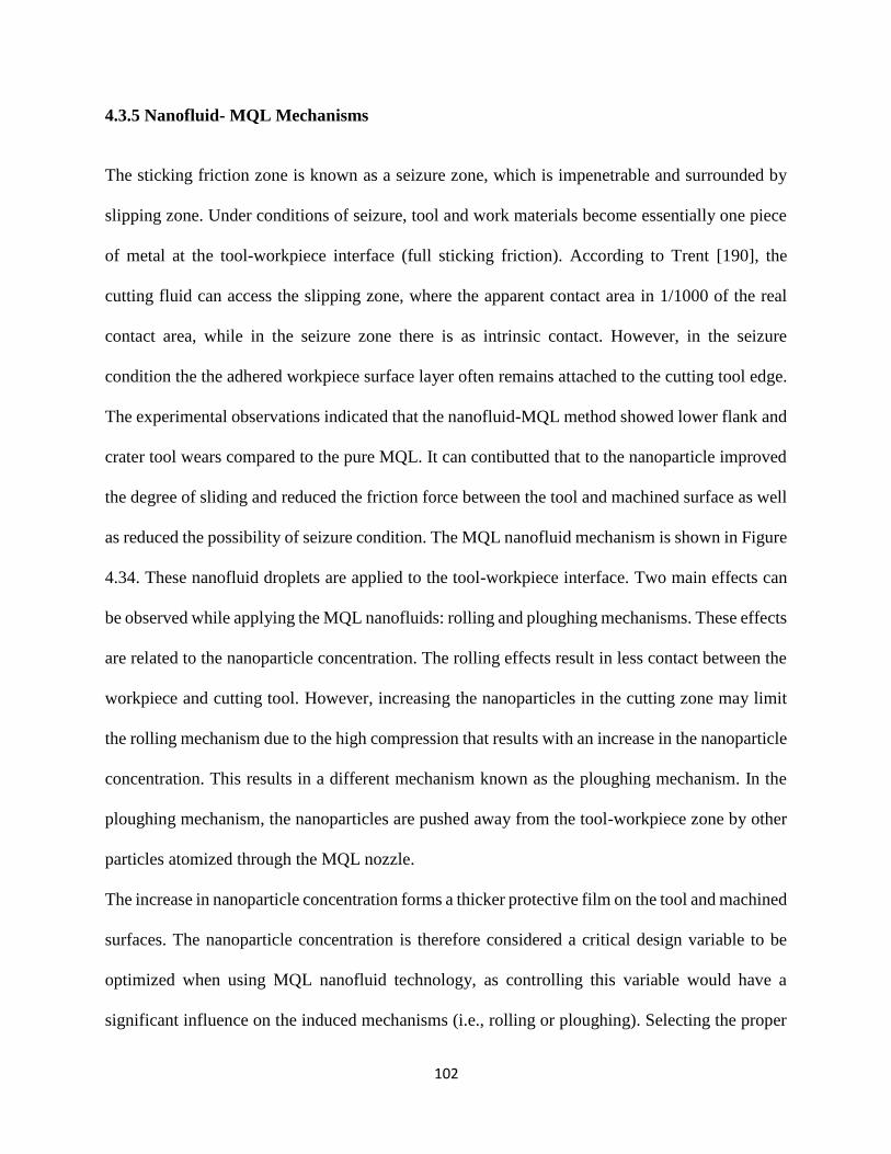
102
102
4.3.5 Nanofluid- MQL Mechanisms
The sticking friction zone is known as a seizure zone, which is impenetrable and surrounded by
slipping zone. Under conditions of seizure, tool and work materials become essentially one piece
of metal at the tool-workpiece interface (full sticking friction). According to Trent [190], the
cutting fluid can access the slipping zone, where the apparent contact area in 1/1000 of the real
contact area, while in the seizure zone there is as intrinsic contact. However, in the seizure
condition the the adhered workpiece surface layer often remains attached to the cutting tool edge.
The experimental observations indicated that the nanofluid-MQL method showed lower flank and
crater tool wears compared to the pure MQL. It can contibutted that to the nanoparticle improved
the degree of sliding and reduced the friction force between the tool and machined surface as well
as reduced the possibility of seizure condition. The MQL nanofluid mechanism is shown in Figure
4.34. These nanofluid droplets are applied to the tool-workpiece interface. Two main effects can
be observed while applying the MQL nanofluids: rolling and ploughing mechanisms. These effects
are related to the nanoparticle concentration. The rolling effects result in less contact between the
workpiece and cutting tool. However, increasing the nanoparticles in the cutting zone may limit
the rolling mechanism due to the high compression that results with an increase in the nanoparticle
concentration. This results in a different mechanism known as the ploughing mechanism. In the
ploughing mechanism, the nanoparticles are pushed away from the tool-workpiece zone by other
particles atomized through the MQL nozzle.
The increase in nanoparticle concentration forms a thicker protective film on the tool and machined
surfaces. The nanoparticle concentration is therefore considered a critical design variable to be
optimized when using MQL nanofluid technology, as controlling this variable would have a
significant influence on the induced mechanisms (i.e., rolling or ploughing). Selecting the proper
103
103
nanoparticle concentration would thus help to achieve better frictional behavior while avoiding the
drastic influence of the ploughing mechanism.
Figure 4.34The MQL-nanofluids mechanisms (a) rolling effect and (b) ploughing effect.
Ultimately, the MQL-nanofluid approach is an effective interactive technique for lubricating and
cooling can be used as a sustainable cooling strategy during machining Ti-6Al-4V titanium alloy.
4.3.6 Conclusion
In this work, MQL nanofluid technology was employed when machining Ti-6Al-4V. Cutting
speed, feed rate, and different nanoparticle concentrations (wt. %) was selected as the design
variables to be studied. Three machining outputs were investigated in this study: machined surface
quality; tool life; and power consumption. ANOVA tests were conducted to analyze the design
104
104
variable effects on three machining outputs. According to ANOVA, the feed rate and the
nanoparticle concentration were the most significant parameters in determining the surface
roughness at contribution rates of 46.55% and 40.75% respectively. The ANOVA analysis also
showed that the nanofluid at 2 and 4 wt. % concentration of Al2O3 provided better results than the
regular MQL in determining surface roughness. Tool wear was also found to be affected by
nanoparticle concentration. The analysis indicated that the nanoparticle concentration influenced
the flank wear at a contribution rate of 42.65 %. The nanoparticles which were used enhanced the
thermal conductivity and lubrication properties of the MQL based cutting fluid. They also
minimized the coefficient of friction between the tool-workpiece as well as reduced the possibility
of seizure condition. In terms of the power consumption, the lowest power consumption was
noticed at a feed rate of 0.2 mm/rev, a cutting speed of 170 m/min, and nanoparticle concentration
of 4 wt. %. Furthermore, a detailed mechanism for MQL nanofluid was discussed. Two main
effects (i.e., ploughing and rolling) were presented and investigated. In addition, the relationship
between these effects and the nanoparticle concentrations were highlighted. Applying MQL
nanofluid showed better results in terms of improving the tool performance, surface quality, and
power consumption when compared to the classical MQL. In the future, more work could be done
to determine the appropriate nanoparticle concentration needed to achieve better frictional
behavior while avoiding the drastic influence of the ploughing mechanism.
105
105
Chapter 5: Sustainability Assessment of Machining Difficult-to-Cut
Materials
5.1 Introduction
Recently, when considering manufacturing processes, a sustainability assessment methodology is
a crucial issue. Life Cycle Assessment (LCA) methodology can be utilized to assess the
manufacturing operations. However, it is essential to study the concept of sustainable
manufacturing at different levels, including the process, the product, and the system levels, as the
connections between these levels provide the intended sustainability. Joshi et al. [191] replaced
the 3R method (reduce, reuse, and recycle) of sustainable manufacturing with the new sustainable
manufacturing 6R method (reduce, reuse, recover, redesign, remanufacture, and recycle).
Hypothetically, this accomplishes a closed loop and a multiple life-cycle standard. Although this
new approach (6R) includes a wider range of sustainability characteristics, it does not contain an
independent tool to optimize the process. Thus, an effective assessment tool which may provide
sustainable and optimal solutions is necessary. In this work, a previous assessment algorithm
[101] was used to assess the cutting processes for Ti-6Al-4V titanium alloy to estimate the levels
of sustainable design variables, while considering sustainable indicators as well as the machining
responses (i.e. flank wear (VB) and surface roughness (Ra)). This algorithm concentrates on the
three major aspects of sustainability, namely economic, environmental, and societal. This
algorithm includes five main steps:
defining the machining outputs and sustainable indicators
determining the sustainable factors (i.e. the interaction effect between the machining
outputs and the sustainable indicators)
determining the sustainable index (SI) (i.e. the normalization step)
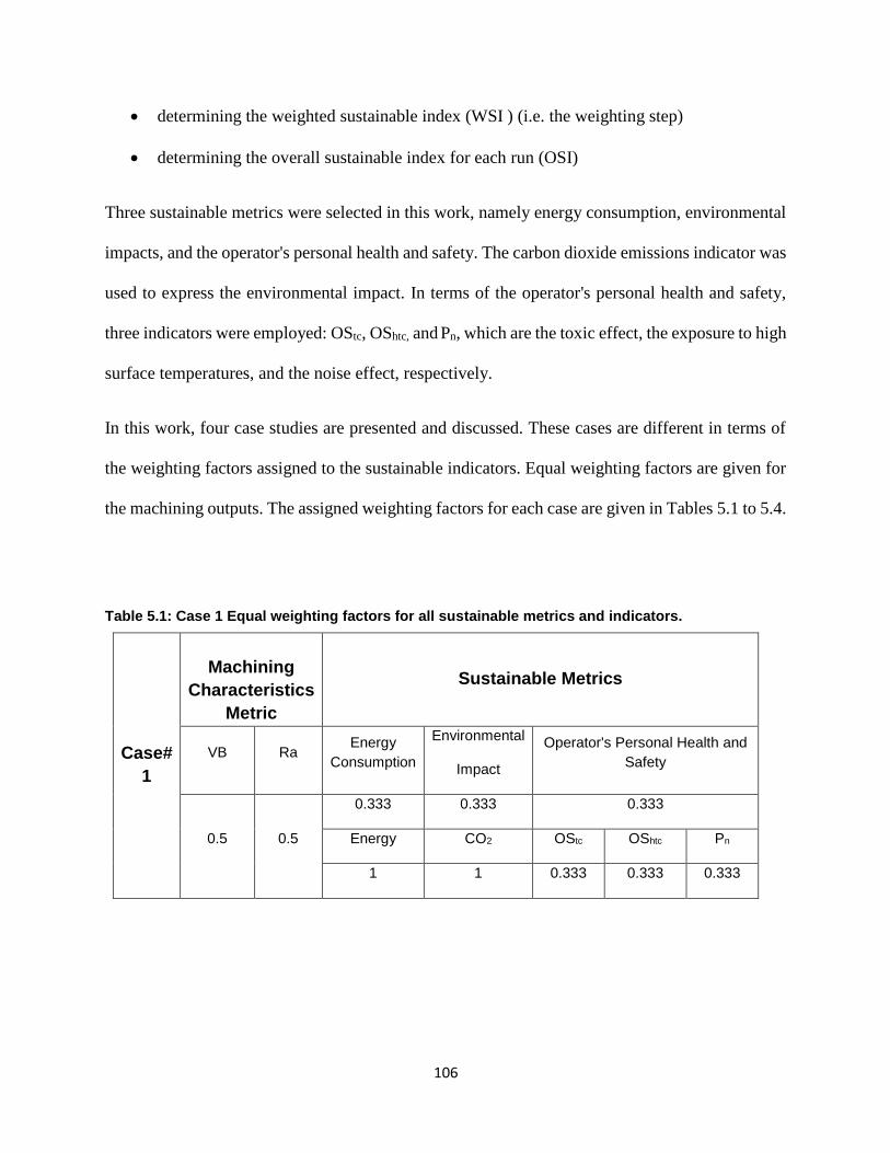
106
106
determining the weighted sustainable index (WSI ) (i.e. the weighting step)
determining the overall sustainable index for each run (OSI)
Three sustainable metrics were selected in this work, namely energy consumption, environmental
impacts, and the operator's personal health and safety. The carbon dioxide emissions indicator was
used to express the environmental impact. In terms of the operator's personal health and safety,
three indicators were employed: OStc, OShtc, and Pn, which are the toxic effect, the exposure to high
surface temperatures, and the noise effect, respectively.
In this work, four case studies are presented and discussed. These cases are different in terms of
the weighting factors assigned to the sustainable indicators. Equal weighting factors are given for
the machining outputs. The assigned weighting factors for each case are given in Tables 5.1 to 5.4.
Table 5.1: Case 1 Equal weighting factors for all sustainable metrics and indicators.
Case#
1
Machining
Characteristics
Metric
Sustainable Metrics
VB Ra Energy
Consumption
Environmental
Impact
Operator's Personal Health and
Safety
0.5 0.5
0.333 0.333 0.333
Energy CO2 OStc OShtc Pn
1 1 0.333 0.333 0.333
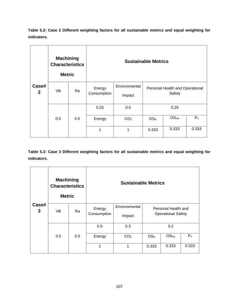
107
107
Table 5.2: Case 2 Different weighting factors for all sustainable metrics and equal weighting for
indicators.
Case#
2
Machining
Characteristics
Metric
Sustainable Metrics
VB Ra Energy
Consumption
Environmental
Impact
Personal Health and Operational
Safety
0.5 0.5
0.25 0.5 0.25
Energy CO2 OStc OShtc Pn
1 1 0.333 0.333 0.333
Table 5.3: Case 3 Different weighting factors for all sustainable metrics and equal weighting for
indicators.
Case#
3
Machining
Characteristics
Metric
Sustainable Metrics
VB Ra Energy
Consumption
Environmental
Impact
Personal Health and
Operational Safety
0.5 0.5
0.5 0.3 0.2
Energy CO2 OStc OShtc Pn
1 1 0.333 0.333 0.333
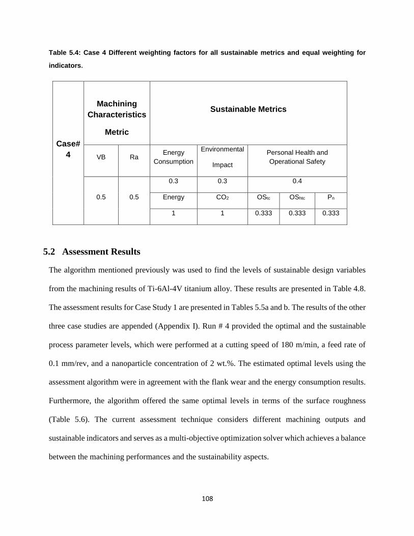
108
108
Table 5.4: Case 4 Different weighting factors for all sustainable metrics and equal weighting for
indicators.
Case#
4
Machining
Characteristics
Metric
Sustainable Metrics
VB Ra Energy
Consumption
Environmental
Impact
Personal Health and
Operational Safety
0.5 0.5
0.3 0.3 0.4
Energy CO2 OStc OShtc Pn
1 1 0.333 0.333 0.333
5.2 Assessment Results
The algorithm mentioned previously was used to find the levels of sustainable design variables
from the machining results of Ti-6Al-4V titanium alloy. These results are presented in Table 4.8.
The assessment results for Case Study 1 are presented in Tables 5.5a and b. The results of the other
three case studies are appended (Appendix I). Run # 4 provided the optimal and the sustainable
process parameter levels, which were performed at a cutting speed of 180 m/min, a feed rate of
0.1 mm/rev, and a nanoparticle concentration of 2 wt.%. The estimated optimal levels using the
assessment algorithm were in agreement with the flank wear and the energy consumption results.
Furthermore, the algorithm offered the same optimal levels in terms of the surface roughness
(Table 5.6). The current assessment technique considers different machining outputs and
sustainable indicators and serves as a multi-objective optimization solver which achieves a balance
between the machining performances and the sustainability aspects.

109
109
In addition, in all case studies, the nanoparticle concentration of 2 wt. % was the optimal
sustainable value; however, 4 wt. % of nanoparticles offered a better machining performance as
discussed in Chapter 4. Some previous studies have claimed that the interaction between the
ploughing and the rolling mechanisms has a physical relationship with the nanoparticle
concentration [98, 100]. Thus, it can be concluded that the nanoparticle concentration effects need
to be further emphasized in order to understand the physical effect on the machining quality
performance as the nanoparticle affects the tribological and heat transfer characteristics when
machining with nano-cutting fluids.
Table 5.5 (a): Case (1) Sustainable Factors and Sustainable indexes (A: cutting speed, B: feed rate,
and C: nanoparticle concentration wt. %)

110
110
Table 5.5 (b): Case (1): Weighted Sustainable index.
Table 5.6: Assessment algorithm outputs versus optimal machining experimental outputs.
Experimental test responses
Assessment algorithm outputs
optimal machining experimental outputs
Max flank wear (mm) 0.19 0.153
Surface roughness (µm) 0.512 0.512
Energy consumption
(kWh)
2.079 1.959
5.3 Conclusion
In this chapter, the sustainability effects were found to be optimized during the cutting process of
Ti-6Al-4V when using nano-cutting fluids. Achieving a sustainable environment for machining
processes is important, and therefore, the integration of machining outputs and sustainable
indicators is a promising step towards this goal. In this work, three sustainable metrics were
selected, namely energy consumption, environmental impact, and the operator's personal health
and safety. In addition, different weighting factors were employed to find the level of sustainable
process parameters. The results showed that the optimal combination of sustainable process
parameters was a cutting speed of 180 m/min, a feed rate of 0.1 mm/rev, and a nanoparticle
111
111
concentration of 2 wt. % (Run # 4). There was good agreement between the assessment algorithm
outputs and the optimal machining experimental outputs for flank wear, surface roughness, and
energy consumption. The current model has the ability to be a multi-objective optimization solver
because it can take into consideration both machining characteristics and environmental impacts.
Finally, more focus should be given to understanding the physical effects of nanoparticle
concentrations on the tribological and heat transfer characteristics during machining with nano-
cutting fluids.
112
112
Chapter 6: Modelling and Numerical Simulation
An Integrated Numerical Model for Using Minimum Quantity Lubrication
(MQL) When Machining Austempered Ductile Iron (ADI)
6.1 Introduction
The cutting temperature and the thermal behaviour of the cutting process are the key factors
affecting the tool wear mechanism and the tool life. Cutting fluids are required to reduce the high
heat generated during machining process, particularly when machining difficult-to-cut materials
such as austempered ductile iron (ADI) and Ti-6Al-4V [192, 193]. Flood coolant is an effective
approach to eliminate the high generated heat when machining ADI. However, the use of
conventional flood coolant is not a sustainable cooling approach because it costly and negatively
impacts the operator’s health and the environment. The cost of the cooling lubricant ranges from
7% to 17% of the total machining costs [194] while the tool cost is only between 2 to 4% [195].
Previous researches have focused on proposing a sustainable cooling approach when machining
difficult-to-cut materials. Minimum quantity lubrication (MQL) is one of the environmentally
friendly cooling approaches, which has been demonstrated to be an effective near dry machining
technique. Instead of costly experimental research, several researchers have claimed that
computational fluid dynamics CFD analysis coupled with FEM, or virtual prototyping, would be
a powerful method for predicting the temperature of various cutting fluids [196]. Virtual
prototyping remains a cheaper, more environmentally friendly, and faster approach to testing the
effectiveness of the coolant strategy, while CFD analysis is a computational resolution of the
Navier-Stokes equations in the fluid domain [197]. Researchers have tried to model the air-oil
mixture flow using a discrete phase model (DPM). For example, Balan et al. [198] investigated
the oil droplet characteristics as a function of inlet parameters. They found that the droplet size
decreased as the flow rate and atomization pressure increased. They reported that for better
113
113
lubrication and wettability, medium-sized mist droplets with a diameter between 6-16.3 µm should
be used. The solid-mist interaction results were obtained through experiment setups only, using
different flow configurations.
ADI remains one of the hard-to-cut materials, and its machinability has interested several
researchers. Klöpper [199] has dedicated his research efforts to identifying the machining
characteristics of ADI. This study investigated the relationship between the cutting parameters and
different machining outputs. Arft and Klocke [200] analyzed the effect of tool geometry on cutting
forces. An optimized geometry was designed by means of FE analysis. However, few researchers
have investigated the MQL application when machining ADI. For example, Eltaggaz et al. [98,
153] investigated the relationship between design cutting parameters and machining aspects (tool
life, surface roughness, and power consumption) of ADI using dry, flood, MQL, and nanofluid-
MQL cooling conditions. It was found that adding nanoparticles to the MQL base oil (nanofluid-
MQL) extended the tool life and improved the machined surface quality. Previous studies were
mainly focused on using MQL-nano-fluid approach while turning alloys such as Inconel 718 [100]
and Ti-6Al-4V [29].
To the best of the author’s knowledge, there is a gap in the open literature on the ADI turning
process regarding numerical modelling of the thermal interaction. Thus, this research focuses on
simulating the cutting heat distribution on the cutting tool during the machining of ADI. It also
develops a model to predict the cutting tool tip temperature and to evaluate the MQL's cooling
ability. As the constitutive equation for ADI is not available by default because of its contradictory
nature, there is no study in which an FE model of machining simulation is performed for ADI.
114
114
In this study, a 2D commercial ABAQUS explicit code was used with the user defined subroutine
VUHARD in order to determine the maximum temperature when cutting ADI under MQL and dry
conditions. The ABAQUS subroutine "VUHARD" was therefore coded for this purpose: the
subroutine's role is to calculate the equivalent stress in each iteration according to the stress flow
formula given by the Broddmann Equation [201]. The subroutine was coded in FORTRAN and
then added to the Abaqus model to solve the problem. Afterwards, the resultant temperature was
mapped into an ANSYS fluent CFD/CHT (coupled heat transfer) to investigate the convective heat
transfer occurring on the rake face since this area is the most exposed to the coolant flow. The
CFD model compared the MQL coolant strategy with dry conditions to predict the heat distribution
on the cutting tool and to evaluate the MQL thermal efficiency. Experimental tests, conducted
using a CNC Lathe on Grade 2 (ADI), validated the numerical model’s results for both dry and
MQL approaches. Thus, the novelty of this work is mainly based on the interactive design
approach as this work offers a new integrated numerical model (FEM & CFD) to simulate the
thermal and heat transfer behavior when machining ADI.
6.2 Experimental Setup
The methodology schematic is shown in Figure 6.1. The FEM of the cutting operation was
developed using the recommended cutting parameters [202]. The temperature of the cutting tool,
which was invoked in the CFD model, was generated by an FEM model and set as a thermal
boundary condition. An accurate instantaneous estimation of the heat coefficient was obtained and
mapped into a transient thermal analysis to observe the temperature evolution as a function of
distance and cutting time. The major difference between the MQL technique and the conventional
fluid coolants is the added conduction that occurs at the exposed surface. Hence, the oil film that
is formed acts as a heat sink. The results from the model were compared to the experiments.
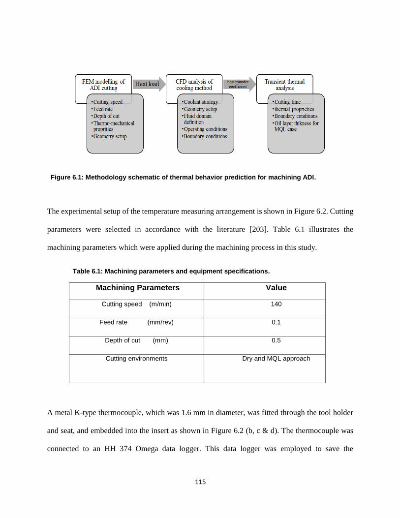
115
115
Figure 6.1: Methodology schematic of thermal behavior prediction for machining ADI.
The experimental setup of the temperature measuring arrangement is shown in Figure 6.2. Cutting
parameters were selected in accordance with the literature [203]. Table 6.1 illustrates the
machining parameters which were applied during the machining process in this study.
Table 6.1: Machining parameters and equipment specifications.
Machining Parameters Value
Cutting speed (m/min) 140
Feed rate (mm/rev) 0.1
Depth of cut (mm) 0.5
Cutting environments Dry and MQL approach
A metal K-type thermocouple, which was 1.6 mm in diameter, was fitted through the tool holder
and seat, and embedded into the insert as shown in Figure 6.2 (b, c & d). The thermocouple was
connected to an HH 374 Omega data logger. This data logger was employed to save the
116
116
temperature values that were obtained during each experiment. Due to the constant contact
between the cutting tool and the workpiece, the thermocouple probe could not be set at the tip. As
seen in Figure 6.2 (b), the thermocouple probe was situated approximately 2 mm away from the
cutting tool tip, where it measured the temperature. The temperature was determined at this point
2 mm from tool tip during the machining of ADI grade 2 under both dry conditions and an MQL
mist. The tooltip temperature can be extrapolated from the numerical simulation after validation.
The fluid supply chain ends with a convergent nozzle ordered for the purpose. The nozzle
orientation was set manually in order to ensure the maximum wettability of the contact zone. The
outlet nozzle diameter was 2 mm, and it was confirmed that no pressure loss occurred in the fluid
channel.
117
117
Figure 6.2: Experimental setup view (a); the installation and arrangements for the cutting
temperature measurements (b), (c) & (d).
The machining experiment was executed using a sample of ADI grade 2 as a workpiece. Table 6.2
presents the thermo-mechanical properties of ADI grade 2 as stated in the ASTM A897 standard
specifications. Table 6.3 shows the properties of the uncoated tungsten carbide cutting tool. It
consists of H13A grade materials which are known for their strong wear resistance and toughness.
118
118
Table 6.2: Thermo-mechanical properties of the ADI grade 2. [201, 202]
Property Value Property Value
Modulus of elasticity (GPa) 157.9 Thermal conductivity (w/m.k) 21.8
Poisson’s ratio 0.25 Specific heat (J/Kg.k) 461
Thermal expansion coefficient
(mm/mm/°C×10-6)
14.3 Modulus of elasticity (GPa) 157.9
Table 6.3: Thermo-mechanical properties of CCMT 12 04 04-KM (uncoated carbide). [203]
Property Value
Modulus of elasticity (GPa) 670
Poisson’s ratio 0.25
Thermal conductivity (w/m.k) 46
Specific heat (J/Kg.k) 203

119
119
6.3 Finite Element Modeling
6.3.1 ADI Model for Orthogonal Turning Process
In order to obtain the temperature distribution throughout the workpiece and the cutting tool, a
finite element model of the turning operation was simulated using a 2D commercial explicit
dynamic code. ABAQUS Explicit 14.6 was used as it is robust and reliable. Using an Explicit
dynamic solver is highly recommended for extreme nonlinear material behaviour and phenomena
involving high deformations and strains [204]. The geometry was sketched with the real
dimensions of the cutting tool, and the features of the assembly were meshed using CPERT4
elements which allowed the temperature to be calculated as a nodal variable. The flow stress
behaviour of the ADI was modelled using the Brodmann formulation [201] with the appropriate
material constants as advised in the literature [199, 202]. This material model is not available by
default; therefore the user defined subroutine VUHARD was used in each iteration for flow stress
calculations. An accurate flow stress calculation is important for a representative thermal behavior
since the temperature increase is due to plastic deformation, as shown in Equation (6.1):
ρ. c(T). T = η. σ. εpl … … … … … … … … … … … … … … … … … … … (6.1)
Where ρ is the material density, c is the material specific heat, T is the temperature rate, and η is
the inelastic heat fraction which is set to 0.9 for this study, while σ and εpl are the flow stress and
the plastic strain respectively. Equation (6.2) presents the constitutive equation, which describes
the flow stress as function of the strain, strain rate and temperature:
σ(ε, ε, T) = (K1 + K. εn + η. ε). ψ(T). χ(ε, ε, T) … … … … … … … … … … … . . (6.2)
120
120
Where (T) describes the thermal softening that occurs due to the high temperature values reached
during cutting as shown in Equation (6.3). In addition, the χ function is added to take into account
the ductile softening behavior as shown in Equation (6.4). The design parameters used for this
study are provided in Table 6.4.
(T) = e−β.(T−T0)
Tm … … … … … … … … … … … … … … . (6.3)
χ(ε, ε, T) = 1 − e−εG.εG.T
ε.ε.TG … … … … … … … … … … … … … … (6.4)
Table 6.4 Parameters for constitutive material law. [199]
Parameter Value Parameter Value Parameter Value
K1 55 [MPa] K 2000.6 [MPa] n 0.1006
η ]2Ns/m[ 0.0292 mT 1800 [K] β 3 [MPa/K]
Gε 33000 εG ]1-s[2000 GT 100 [K]
A fully coupled temperature displacement explicit solver was chosen with a local Arbitrary
Lagranian Eulerian (ALE) formulation in order to prevent distortion errors; enhanced hourglass
control was also activated to prevent any hourglass effect. The mesh was finer in the cutting zone.
The model results have been ensured to be independent of mesh size through performing several
comparisons with other trials with smaller mesh size. The total number of elements was 300, 000.
No intermediate sacrifice layer was therefore defined between the chip and the non-machined
workpiece zone. Boundary conditions were neatly introduced to replicate the cutting conditions,
as shown in Figure 6.3. The machined part of the workpiece was sloped to prevent distortion. The
simulation was carried out as a 2D representation; the depth of the cut was set as a shell thickness
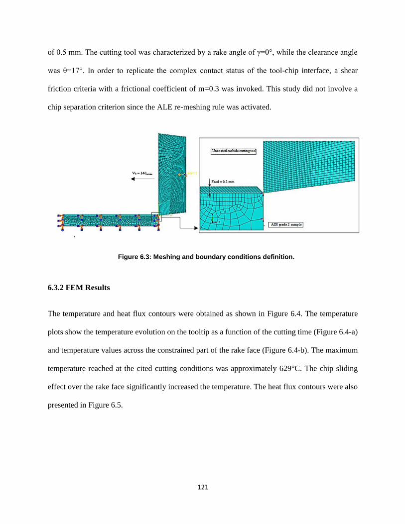
121
121
of 0.5 mm. The cutting tool was characterized by a rake angle of γ=0°, while the clearance angle
was θ=17°. In order to replicate the complex contact status of the tool-chip interface, a shear
friction criteria with a frictional coefficient of m=0.3 was invoked. This study did not involve a
chip separation criterion since the ALE re-meshing rule was activated.
Figure 6.3: Meshing and boundary conditions definition.
6.3.2 FEM Results
The temperature and heat flux contours were obtained as shown in Figure 6.4. The temperature
plots show the temperature evolution on the tooltip as a function of the cutting time (Figure 6.4-a)
and temperature values across the constrained part of the rake face (Figure 6.4-b). The maximum
temperature reached at the cited cutting conditions was approximately 629°C. The chip sliding
effect over the rake face significantly increased the temperature. The heat flux contours were also
presented in Figure 6.5.
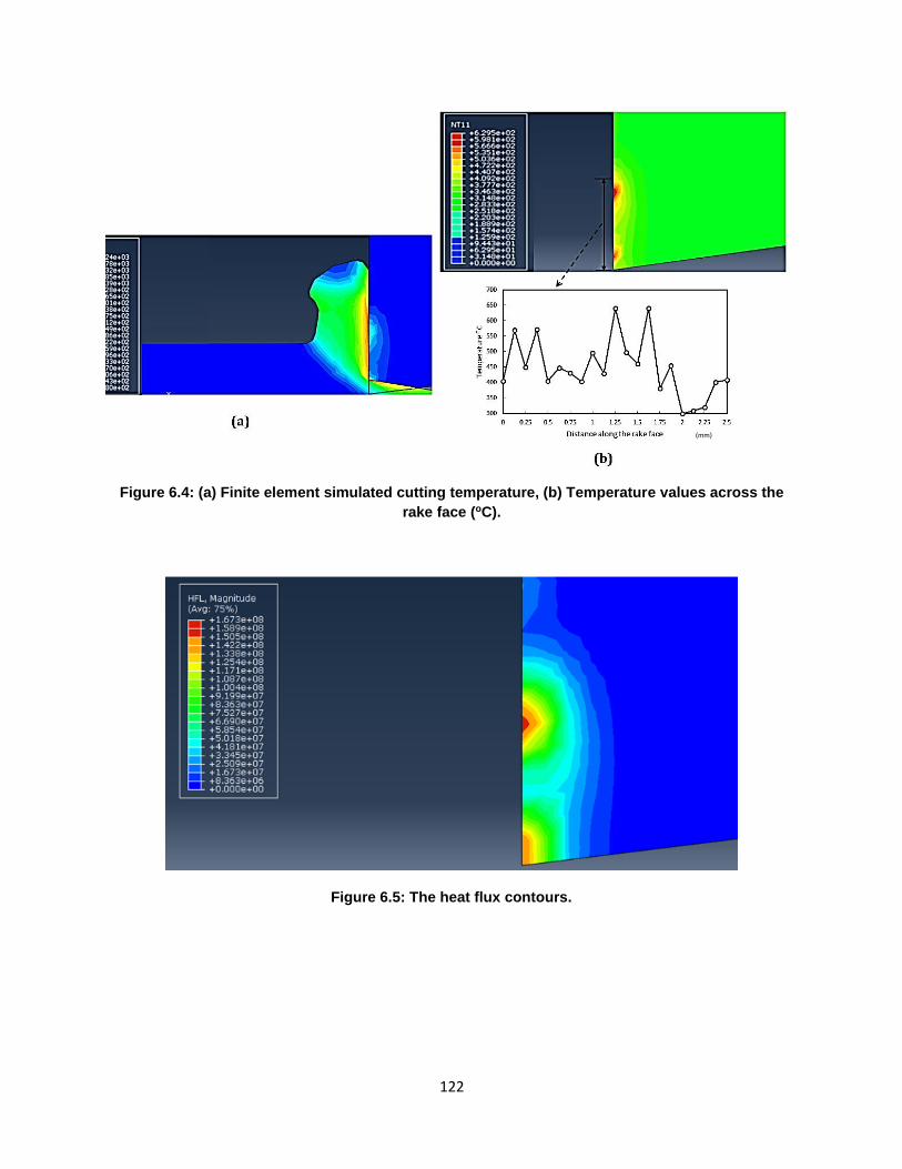
122
122
Figure 6.4: (a) Finite element simulated cutting temperature, (b) Temperature values across the
.C)orake face (
Figure 6.5: The heat flux contours.
(mm)
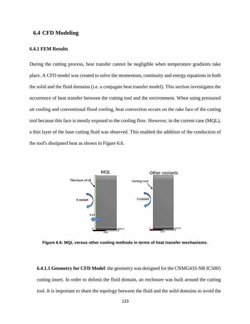
123
123
6.4 CFD Modeling
6.4.1 FEM Results
During the cutting process, heat transfer cannot be negligible when temperature gradients take
place. A CFD model was created to solve the momentum, continuity and energy equations in both
the solid and the fluid domains (i.e. a conjugate heat transfer model). This section investigates the
occurrence of heat transfer between the cutting tool and the environment. When using pressured
air cooling and conventional flood cooling, heat convection occurs on the rake face of the cutting
tool because this face is mostly exposed to the cooling flow. However, in the current case (MQL),
a thin layer of the base cutting fluid was observed. This enabled the addition of the conduction of
the tool's dissipated heat as shown in Figure 6.6.
Figure 6.6: MQL versus other cooling methods in terms of heat transfer mechanisms.
6.4.1.1 Geometry for CFD Model: the geometry was designed for the CNMG433-NR IC5005
cutting insert. In order to delimit the fluid domain, an enclosure was built around the cutting
tool. It is important to share the topology between the fluid and the solid domains to avoid the
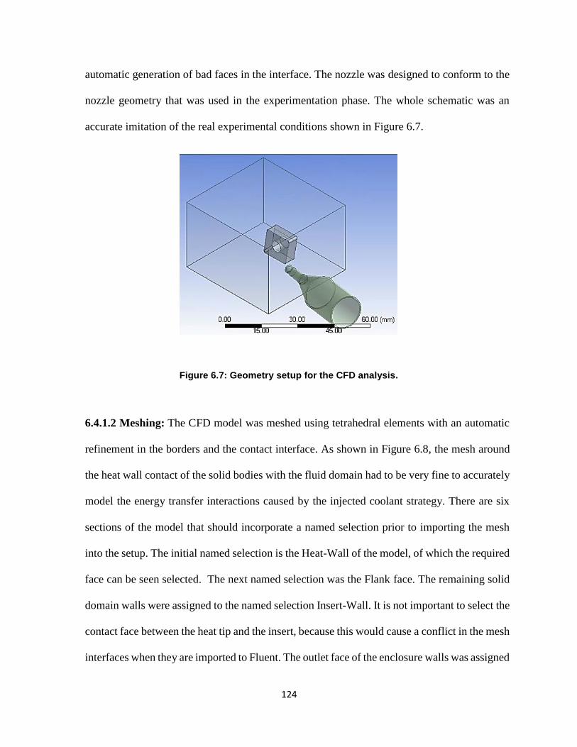
124
124
automatic generation of bad faces in the interface. The nozzle was designed to conform to the
nozzle geometry that was used in the experimentation phase. The whole schematic was an
accurate imitation of the real experimental conditions shown in Figure 6.7.
Figure 6.7: Geometry setup for the CFD analysis.
6.4.1.2 Meshing: The CFD model was meshed using tetrahedral elements with an automatic
refinement in the borders and the contact interface. As shown in Figure 6.8, the mesh around
the heat wall contact of the solid bodies with the fluid domain had to be very fine to accurately
model the energy transfer interactions caused by the injected coolant strategy. There are six
sections of the model that should incorporate a named selection prior to importing the mesh
into the setup. The initial named selection is the Heat-Wall of the model, of which the required
face can be seen selected. The next named selection was the Flank face. The remaining solid
domain walls were assigned to the named selection Insert-Wall. It is not important to select the
contact face between the heat tip and the insert, because this would cause a conflict in the mesh
interfaces when they are imported to Fluent. The outlet face of the enclosure walls was assigned
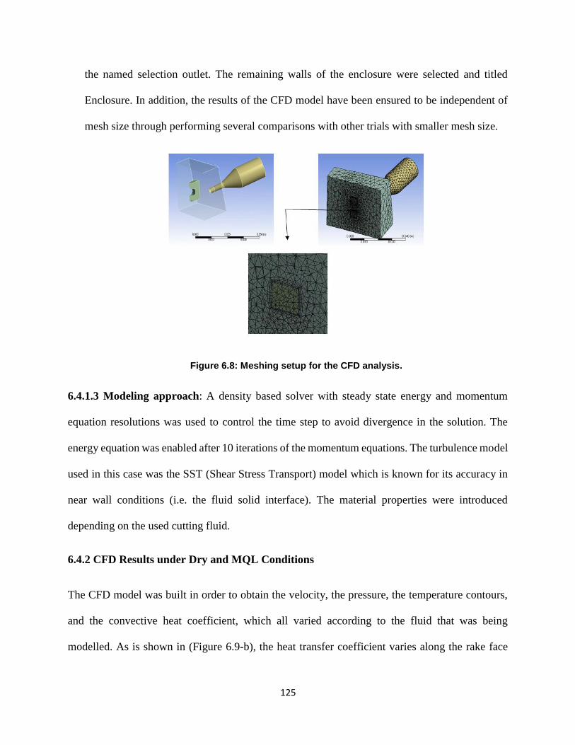
125
125
the named selection outlet. The remaining walls of the enclosure were selected and titled
Enclosure. In addition, the results of the CFD model have been ensured to be independent of
mesh size through performing several comparisons with other trials with smaller mesh size.
Figure 6.8: Meshing setup for the CFD analysis.
6.4.1.3 Modeling approach: A density based solver with steady state energy and momentum
equation resolutions was used to control the time step to avoid divergence in the solution. The
energy equation was enabled after 10 iterations of the momentum equations. The turbulence model
used in this case was the SST (Shear Stress Transport) model which is known for its accuracy in
near wall conditions (i.e. the fluid solid interface). The material properties were introduced
depending on the used cutting fluid.
6.4.2 CFD Results under Dry and MQL Conditions
The CFD model was built in order to obtain the velocity, the pressure, the temperature contours,
and the convective heat coefficient, which all varied according to the fluid that was being
modelled. As is shown in (Figure 6.9-b), the heat transfer coefficient varies along the rake face
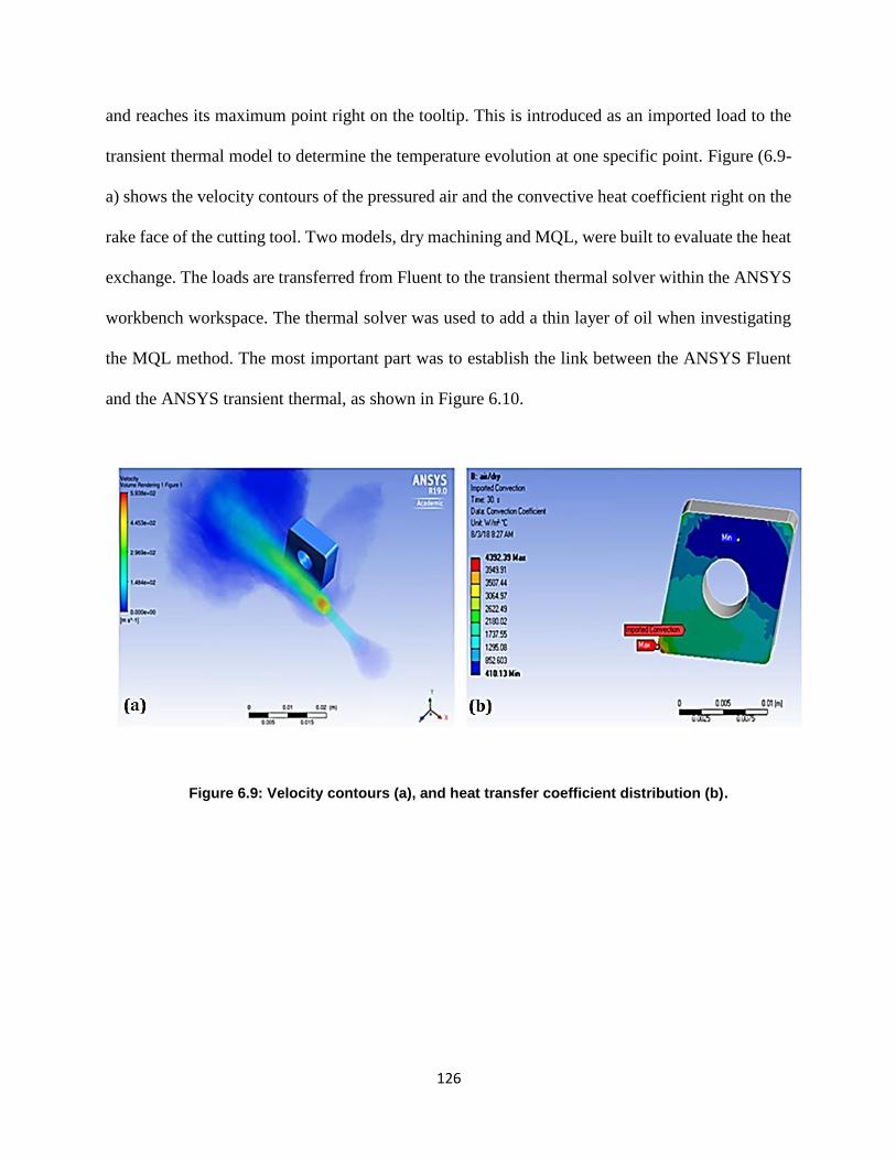
126
126
and reaches its maximum point right on the tooltip. This is introduced as an imported load to the
transient thermal model to determine the temperature evolution at one specific point. Figure (6.9-
a) shows the velocity contours of the pressured air and the convective heat coefficient right on the
rake face of the cutting tool. Two models, dry machining and MQL, were built to evaluate the heat
exchange. The loads are transferred from Fluent to the transient thermal solver within the ANSYS
workbench workspace. The thermal solver was used to add a thin layer of oil when investigating
the MQL method. The most important part was to establish the link between the ANSYS Fluent
and the ANSYS transient thermal, as shown in Figure 6.10.
Figure 6.9: Velocity contours (a), and heat transfer coefficient distribution (b).

127
127
Figure 6.10: ANSYS Fluent/ANSYS transient thermal coupled link.
Regarding the dry machining results, A FEM model was developed to predict the cutting tool tip
temperature when machining ADI using dry conditions. The temperature recorded at a distance of
2 mm away from the tool nose was 109.7oC (approximately 2mm inside the rake face). To verify
the FEM model results, dry machining was conducted on the ADI workpiece. The thermocouple
was placed 2 mm away from the cutting tool tip. Figure 6.11 illustrates the results obtained from
the thermocouple data logger, which are plotted as temperature (oC) vs time (s). The dry cutting
temperature distribution continually rises due to the lack of coolant. The maximum temperature
during machining was 116oC. Due to the location of the thermocouples, the temperature was
recorded over ten seconds period while cutting was being performed. The simulated temperature
values were in good agreement with the experimental results with an error of 5.74%.
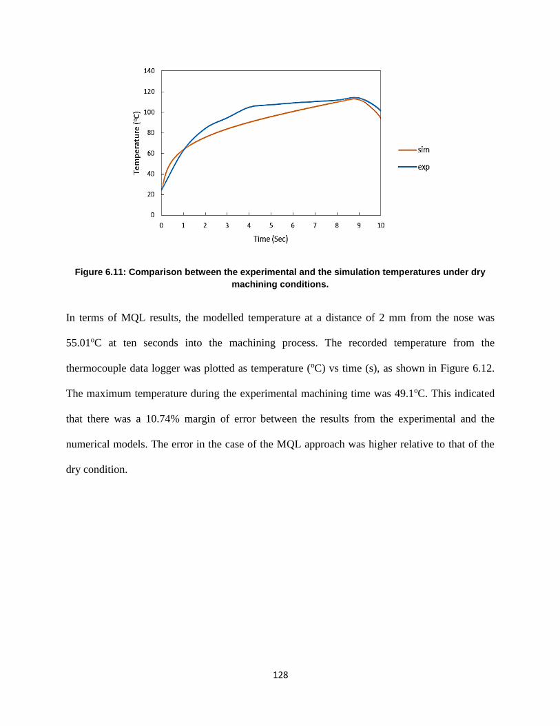
128
128
Figure 6.11: Comparison between the experimental and the simulation temperatures under dry
machining conditions.
In terms of MQL results, the modelled temperature at a distance of 2 mm from the nose was
55.01oC at ten seconds into the machining process. The recorded temperature from the
thermocouple data logger was plotted as temperature (oC) vs time (s), as shown in Figure 6.12.
The maximum temperature during the experimental machining time was 49.1oC. This indicated
that there was a 10.74% margin of error between the results from the experimental and the
numerical models. The error in the case of the MQL approach was higher relative to that of the
dry condition.
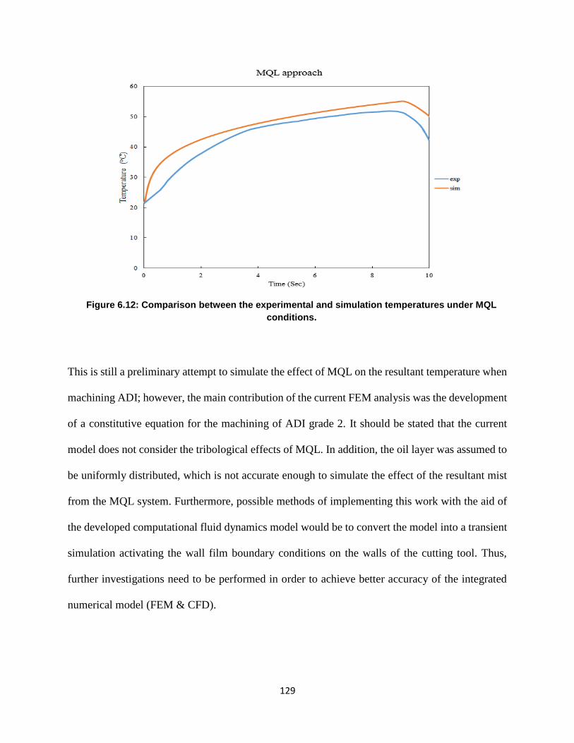
129
129
Figure 6.12: Comparison between the experimental and simulation temperatures under MQL
conditions.
This is still a preliminary attempt to simulate the effect of MQL on the resultant temperature when
machining ADI; however, the main contribution of the current FEM analysis was the development
of a constitutive equation for the machining of ADI grade 2. It should be stated that the current
model does not consider the tribological effects of MQL. In addition, the oil layer was assumed to
be uniformly distributed, which is not accurate enough to simulate the effect of the resultant mist
from the MQL system. Furthermore, possible methods of implementing this work with the aid of
the developed computational fluid dynamics model would be to convert the model into a transient
simulation activating the wall film boundary conditions on the walls of the cutting tool. Thus,
further investigations need to be performed in order to achieve better accuracy of the integrated
numerical model (FEM & CFD).
130
130
6.5 Conclusion
The current work focuses on simulating the cutting heat distribution on the cutting tool during
machining of ADI by developing an integrated numerical model (finite element & computational
fluid dynamics). The investigations within this work were focused on the cutting temperature (i.e.
2 mm away from the tool nose for both dry cutting and MQL cooling). In terms of dry cutting, the
simulated temperature values were in good agreement with the experimental results with an error
of 5.74%. Regarding the MQL, there was a 10.74% margin of error between the results from the
experimental and the integrated numerical model. Overall, the temperatures obtained using the
model for the dry condition was in good agreement with the experimentally obtained temperatures.
However, the CFD model error in the MQL simulation was relatively high when compared to the
dry test. This is still a preliminary attempt to simulate the effect of MQL on the resultant
temperature when machining ADI; however, the main contribution of the current FEM analysis
was the development of a constitutive equation for the machining of ADI grade 2. Finally, further
modifications can be added to the current integrated model to enhance its accuracy such as;
considering the tribological effects of MQL, and developing a transient CFD model.
131
131
Chapter 7: Conclusions and Future Work
This chapter provides the conclusions drawn from the current research and presents the plans for
future work in this area. This thesis focused on investigating the effects of cutting design variables
and cooling strategies on machining characteristics during the machining of both a Ti-6Al-4V
alloy and ADI. The current research also attempted to enhance the cooling ability, viscosity, and
thermal conductivity of the sustainable cooling strategy (nanofluid-MQL) by adding Al2O3 nano-
additives. This was achieved by performing turning tests with appropriate cutting tools and the
recommended range of cutting parameters. In addition to experimental activities, finite element
modeling (FEM) was used to predict the tool tip temperature and the distribution of the temperature
in the cutting zone when machining ADI under dry conditions. Computational fluid dynamics
(CFD) was also used to evaluate the MQL cooling performance during the turning of ADI. The
main conclusions from this work can be summarized as follows:
The overall cutting performance benefits from applying a nanofluid-MQL as this is a
sustainable cooling strategy with a good performance. The use of a nanofluid-MQL
reduced the cutting temperature and the friction in the cutting zone, and consequently
reduced the tool wear, the power consumption, and the cutting forces. Adding Al2O3
nanoparticles to the vegetable-oil based MQL markedly enhanced the lubricity and the
thermal conductivity of the nanofluid-MQL, and improved its machining performance by
enhancing its viscosity and thermal conductivity.
The nanofluid-MQL technique offered a significant improvement in tool life during the
machining experiments in comparison with the classical MQL. The combination of
nanofluid-MQL 4 wt. % at a cutting speed of 120 m/min and a feed rate of 0.2 mm/rev
showed the best tool life during the machining of ADI.

132
132
Nano-additives placed in a vegetable-oil MQL cooling system improved the convection,
wettability, and conduction characteristics of the proposed nanofluid-MQL; therefore, the
tool wear was significantly reduced because of the tribo-film formation along the tool-
workpiece interface zone. Also, the nanofluid-MQL mist droplets served as spacers to limit
the rubbing induced between the cutting tool and the workpiece, thereby reducing the
coefficient of friction in the cutting zone. Moreover, using a nanofluid-MQL decreased the
rate of tool wear due to the enhanced tribological characteristics contributed by the nano-
additives. Thus, this research has successfully introduced nanofluid-MQL as an effective
interactive approach for cooling and lubrication when machining difficult-to-cut materials
such as ADI and Ti-6Al-4V titanium alloy.
It was also found that the nanoparticle concentration plays a vital role in the tribological
characteristics of the nanofluid-MQL.
The FEM and CFD models used respectively for predicting the cutting temperature distribution
under dry conditions and for evaluating the cooling performance of the MQL approach during the
machining of ADI were found to be in good agreement with the experimental results. The main
contribution of the current FEM analysis was the development of a constitutive equation for the
machining of ADI grade 2. Further modifications can be added to the current integrated model to
enhance its accuracy such as; considering the tribological effects of MQL, and developing a
transient CFD model.
133
133
7.1 Contributions
The current research has contributed to the present knowledge as follows:
• This study addresses the research gap in the literature which relates to the investigation of
nanofluid cooling strategies during the machining of ADI grade 2 and Ti-6Al-4V titanium
alloy using nanoparticles.
• The current study provided a clear understanding of the role of MQL-nano-cutting fluids,
their cooling and lubricating mechanisms, and the ploughing and rolling mechanisms.
• The knowledge gained during this study regarding machining operations, cutting tool
performance, tool wear behavior,and power (energy) consumption can be a solid
foundation to further approaches for improving the machinability of these materials under
a sustainable cooling strategy (e.g. nanofluid- MQL).
• The main contribution of the preliminary numerical phase was the development of the
constitutive equation for the machining of ADI grade 2, which is not readily available in
the open literature.
• The current research developed the knowledge and tools needed to address both
sustainability and technical challenges associated with the machining of difficult-to-cut
materials in terms of tool wear, and surface quality.
7.2 Future Work
Future research should focus on:
• Including more design variables such as different MQL air pressures, MQL volume flow
rates, MQL nozzle orientations, and cutting tool geometries.
134
134
• Investigating a hybrid nano-cutting-fluid; for example, a mixture between MWCNTs and
Al2O3 nanoparticles using volume fractions ranging from 0 to 8 %, as suggested in the
literature.
• Developing an analytical model to explain the relationship between induced nanoparticle
abrasion and nanoparticle concentration and size.
• Performing further research to develop a function to represent the friction coefficient under
MQL operations, which in turn could be used to more accurately model the temperature
generated at the tooltip.
• Enhancing the FEM model and CFD simulation to simulate the MQL-nanofluid.
135
135
References:
[1] Gupta K., Laubscher R. F., and Davim P., "Recent developments in sustainable manufacturing
of gears: a review," Journal of Cleaner Production, vol. 112, pp. 3320-3330, 2016.
[2] Tazehkandi A. H., Shabgard M., Kiani G., and Pilehvarian F., "Investigation of the influences
of polycrystalline cubic boron nitride (PCBN) tool on the reduction of cutting fluid consumption
and increase of machining parameters range in turning Inconel 783 using spray mode of cutting
fluid with compressed air," Journal of Cleaner Production, vol. 135, pp. 1637-1649, 2016.
[3] Davoodi B. and Tazehkandi A. H., "Experimental investigation and optimization of cutting
parameters in dry and wet machining of aluminum alloy 5083 in order to remove cutting fluid,"
Journal of Cleaner Production, vol. 68, pp. 234-242, 2014.
[4] Niketh S. and Samuel G. L., "Surface texturing for tribology enhancement and its application
on drill tool for the sustainable machining of titanium alloy," Journal of Cleaner Production,
vol. 167, pp. 253-270, 2017.
[5] Tazehkandi H., Pilehvarian F.,and Davoodi B., "Experimental investigation on removing cutting
fluid from turning of Inconel 725 with coated carbide tools," Journal of Cleaner Production,
vol. 80, no. 1, pp. 271-281, 2014.
[6] Park D., "The occupational exposure limit for fluid aerosol generated in metalworking
operations: limitations and recommendations," Safety and Health at Work 3.1, pp. 1-10, 8
September 2012.
[7] Bordin A., Sartori S., Bruschi S., and Ghiotti A., "Experimental investigation on the feasibility
of dry and cryogenic machining as sustainable strategies when turning Ti-6Al-4V produced by
Additive Manufacturing," Journal of Cleaner Production, vol. 142, pp. 4142-4151, 2017.
[8] Çolak O., "Optimization of machining performance in high-pressure assisted turning of Ti-6Al-
4V Alloy," Journal of Mechanical Engineering, vol. 60, no. 10, pp. 675-681, 2014.
[8] Metal Asian., "ASIAN METAL , Metal pedia, Titanium uses," ASIAN METAL , [Online].
Available: http://metalpedia.asianmetal.com/metal/titanium/application.shtml. [Accessed 15 04
2016].
[10] Meena A. and El Mansori M., "Study of dry minimum quantity lubrication drilling of novel
austempered ductile iron (ADI) for automotive applications," Elsevier, Wear, vol. 271, no. 9-
10, pp. 2412-2416, 2011.
[11] Klocke F. and Klopper C., "Machining of ADI," WZL Laboratory for Machine Tools and
Production Engineering, Aachen, Germany.
[12] Brandenberg K., "Successfully machining austempered ductile iron (ADI)," Applied Process
Inc., Michgen, USA, 2001.
136
136
[13] Datt D., and Batra U., "Influence of composition and austempering temperature on
machinability of asutempered dutile iron," International Journal of Chemical, Molecular,
Nuclear, Metallurgical Engineering, vol. 7, no. 2, pp. 132-137, 2013.
[14] Padan D. S., "Microalloying in austempered ductile iron (ADI)," American Foundry Society, IL,
USA, 2012.
[15] Nofal A., "Advanced in the metallurgy and applications of ADI," Journal of Metallurgical
Engineering (ME), vol. 2, no. 1, 2013.
[16] ADI Treatments Limited, "Austempered Ductile Iron," ADI Treatments Ltd, [Online].
Available: http://www.aditreatments.com/?p=424. [Accessed 27 11 2016].
[17] esa, "IMPRESS, Supporting Education Across Europe," esa, [Online]. Available:
http://www.spaceflight.esa.int/impress/text/education/Circular%20Motion/Turbine_Blades.ht
ml. [Accessed 24 11 2016].
[18] Veiga C., Davim J. P., and Loureiro A., "Review on machinability of titanium alloys:the process
perspective," Reviews on Advanced Materials science, vol. 34, pp. 148-164, 2013.
[19] Arcam EBM system, "Arcam-Ti-6Al-4V-Titanium-Alloy," Arcam AB, [Online]. Available:
http://www.arcam.com/wp-content/uploads/Arcam-Ti6Al4V-Titanium-Alloy.pdf. [Accessed 7
6 2018].
[20] Akdemir A., "The effect of cutting speed and depth of cut on machinability characteristics of
austempered ductile iron," Journal of Manufacturing Science and Engineering, vol. 134, no. 2,
2012.
[21] Parhad P., Likhite A., Bhatt J., and Peshwe D., "The effect of cutting speed and depth of cut on
surface roughness during machining of austempered ductile iron," Trans Indian Inst Metals, vol.
68, no. 1, pp. 99-108, 2015.
[22] Hegde A., and Sharma S., "Machinability study of manganese alloyed austempered ductile
iron," Journal of the Brazilian Society of Mechanical Sciences and Engineering, pp. 40: 338.
https://doi.org/10.1007/s40430-018-1258-6, 2018.
[23] Meena A., and El Mansori M.,"Specific cutting force, tool wear and chip morphology
characteristics during dry drilling of austempered ductile iron (ADI)," International Journal of
Advance Manufacture Technology, vol. 69, p. 2833–2841, 2013.
[24] Polishetty A., "Machinability and microstructural studies on phase transformations in
Austempered Ductile Iron," PhD Thesis, Auckland University, pp. 46-56, 2011.
[25] Arft M., Klocke F., and Lung D., "Evaluation of the machining aspects of austempered ductile
iron," International Journal of Metalcasting , pp. 35-42, 2012.
[26] Polishetty A., Moshe G., and Littlefair G., "Wear characteristics of ultra-hard cutting tools when
machining ADI," International Journal of Mechanical and Mechatronics Engineering, vol. 10,
no. 1, 2011.
137
137
[27] Meena A., El Mansori M., and Ghidossi P., "Machinability of austempered ductile iron (ADI)
produced by integrated green technology of continuous casting-heat treatment processes," in
International Conference on Advances in Materials and Processing Technologies (AMPT2010),
Paris, France, 2010.
[28] Sinlah A., Handayani D., Voigt R. C., Hayrynen K., Saoub R. M., and Saldana C., "Effects of
microstructure and strength on wear performance in rough milling of austempered ductile iron,"
International Journal of Cast Metals Research, Vols. 1-2, no. 29, pp. 62-67, 2016.
[29] Hegab H., Umer U., Deiab I., and Kishawy H., "Performance evaluation of Ti-6Al-4V
machining using nano-cutting fluids under minimum quantity lubrication," The International
Journal of Advanced Manufacturing Technology, vol. 95, no. 9-12, pp. 4229-4241, 2018.
[30] Hartung P., and Kramer D., "Tool wear in titanium machining," CIRP, , vol. 31, pp. 75-80, 1982.
[31] Maekawa K. and Kitagawa, "Temperature and wear of cutting tools in high-speed machining of
Inconel 718 and Ti-6Al-6V-2Sn," Wear, vol. 2, 1997.
[32] Tuğrul Ö. and Karpat Y., "Multi-objective optimization for turning processes using neural
network modeling and dynamic-neighborhood particle swarm optimization," International
Journal Advance Manufacturing Technology, vol. 8, pp. 234-247, 2007.
[33] Venkata Ramana M., Krishna Mohan Rao G., and Hanumantha Rao D., "Optimization and effect
of process parameters on tool wear in turning of titanium alloy under different machining
conditions," International Journal of Materials, Mechanics and Manufacturing, vol. 2, no. 4,
pp. 272-277, 2014.
[34] Ojolo S. T. and Ogunkomaiya O., "A Study of effect of machining parameters on tool life,"
International Journal of Materials Science and Applications, vol. 5, no. 3, pp. 183-199, 2014.
[35] Narutaki N. and Murakoshi A., "Study on machining of titanium alloys," CIRP Annals -
Manufacturing Technology, vol. 32, no. 1, pp. 65-69, 1983.
[36] Liu Z., Xu J., Han S., and Chen M., "A Coupling method of response surfaces (CRSM) for
cutting parameters optimization in machining titanium alloy under minimum quantity
lubrication (MQL) condition," International Journal of Precision Engineering and
Manufacturing, vol. 14, no. 5, pp. 693-702, 2013.
[37] Narasimhulu A., Venkateswara R., and Sudarsan G., "Dry Machining of Ti-6Al-4V using PVD
coated TiAlN tools," in Proceedings of the World Congress on Engineering, Vol III, London,
UK, 2012.
[38] Ying-lin, Hui-yue, LIU G., and Ming Z., " Use of nitrogen gas in high-speed milling of Ti-6Al-
4V," International Journal of Machine Tools & Manufacture, vol. 49, p. 739–743, 2009.
[39] Heigel J., Whitenton E., Lane B., Donmez M., Madhavan V., and Moscoso-Kingsley W.,
"Infrared measurement of the temperature at the tool–chip interface while machining Ti–6Al–
4V," Journal of Materials Processing Technology, vol. 243, p. 123–130, 2017.
138
138
[40] Ramana V., "Optimization and influence of process parameters on surface roughness in Turning
of titanium alloy under different lubricant conditions," Materials Today: Proceedings, vol. 4 ,
p. 8328–8335, 2017.
[41] Boswell B. and Islam M., "Sustainable cooling method for machining titanium alloy," Materials
Science and Engineering, vol. 114, pp. doi:10.1088/1757-899X/114/1/012021, 2016.
[42] Shaw M. C., "Metal Cutting Principles", New York: Oxford University Press, 1998.
[43] Sharma A. K., Katiyar J. K., Bhaumik S., and Roy S., "Influence of alumina/MWCNT hybrid
nanoparticle additives on tribological properties of lubricants in turning operations," Friction,
pp. https://doi.org/10.1007/s40544-018-0199-5, 2018.
[44] Goindi G. and Sarkar P., "Dry machining: A step towards sustainable machining-challenges and
future directions," Journal of Cleaner Production, vol. 165, pp. 1557-1571, 2017.
[45] Minton T., Ghani S., Sammler F., Bateman F., Furstmann R., and Roeder P., "Temperature of
internally-cooled diamond-coated tools for dry-cutting titanium," International Journal of
Machine Tools and Manufacturing, vol. 75, pp. 27-35, 2013.
[46] Shokrani A., Dhokia V., and Newman S., "Environmentally conscious machining of difficult-
to-machine materials with regard to cutting fluids," International Journal of Machine Tools and
Manufacturing, vol. 83, pp. 83-101, 2012.
[47] Kishawy H., Li L., and El-Wahab A., "Prediction of chip flow direction during machining with
self-propelled rotary tools," International Journal of Machine Tools Manufacture, vol. 12, no.
46, pp. 1680-1688, 2006.
[48] Pervaiz S., "Investigation cooling and lubrication strategies for sustainable machining of
titanium alloys: impact on machinability and environmental performance," KTH Royal Institute
of Technology, Stockholm, 2014.
[49] Pervaiz S., Rashid A., Deiab I., and Nicolescu M., "An experimental investigation on effect of
minimum quantity cooling lubrication (MQCL) in machining titanium alloy (Ti6Al4V) ", The
International Journal of Advanced Manufacturing Technology, vol. 87, pp. 5-8, 2016.
[50] Kitagawa T., Kubo A., and Maekawa K., "Temperature and wear of cutting tools in high speed
machining of Inconel 718 and Ti-6Al-6V2Sn," Wear, vol. 202, pp. 142-148, 1997.
[51] Bagherzadeh A. and Budak E., "Investigation of machinability in turning of diffcult-to-cut
materials using a new cryogenic cooling approach," Tribology International, vol. 119, pp. 510-
520, 2018.
[52] Krajnik P., Pusavec F., and Rashid A., "Nanofluids: properties, applications and sustainability
aspects in materials processing technology," In Advances in Sustainable Manufacturing, pp.
107-113, 2011.
139
139
[53] Raza S. W., Pervaiz S., and Deiab I., "Tool wear patterns when turning of titanium alloy using
sustainable lubrication strategies," International Journal of Precision Engineering and
Manufacturing, vol. 15, no. 9, pp. 1979-1985, 2014.
[54] Krishna P., Srikant R., Padmini R., and Viswaditya, "Application of nanomaterials as
coolants/lubrications in machining," International Advanced Nanomaterials and Emerging
Engineering Technologies (ICANMEET), pp. 674-682, 2013.
[55] Behera B. C., Ghosh S., and Venkateswara P., "Modeling of cutting force in MQL machining
environment considering chip tool contact friction," Tribology International, vol. 117, pp. 283-
295, 2018.
[56] Kaynak Y., "Evaluation of machining performance in cryogenic machining of Inconel 718 and
comparison with dry and MQL machining," International Journal Advanced Manufacture
Technology, vol. 72, p. 919–933, 2014.
[57] Boswell B., Islam M., Davies J., Ginting Y., and Ong A., "A review identifying the effectiveness
of minimum quantity lubrication (MQL) during conventional machining," International Journal
of Advanced Manufacturing and Technology, vol. 92, pp. 321-340, 2017.
[58] Dureja J., Singh R., Singh P., Dogra M., Singh R. and Bhatti M., "Performance evaluation of
coated carbide tool in machining of stainless steel (AISI 202) under minimum quantity
lubrication (MQ), "International Journal of Precision Engineering and Manufacturing Green
Technology, vol. 2, pp. 123-129, 2015.
[59] Klock F. and Eisenblatter G., "Dry cutting," CIRP Annual Manufacturing Technology, vol. 46,
pp. 519-526, 1997.
[60] Tschatsch H. and Reichelt A., "Cutting fluid (coolants and lubricants)," In Applied Machining
Technology, pp. 349-352, 2009.
[61] Tai B., Stephenson D., Furness R., and Shih A., "Minimum quantity lubrication (MQL) in
automotive power train machining," Procedia CIRP, vol. 14, pp. 523-528, 2014.
[62] Leppert T., "Effect of cooling and lubrication conditions on surface topography and turning
process of C45 steel," International Journal of Machine Tools and Manufacture, vol. 51, no. 2,
pp. 120-126, 2011.
[63] Chinchanikar S. and Choudhury S. K., "Hard turning using HiPIMS-coated tools: Wear behavior
under dry and minimum quantity lubrication (MQL)," Measurement, vol. 55, pp. 536-548, 2014.
[64] Weinert K., Inasaki I., Sutherland J., and Wakabayashi T., "Dry machining and minimum
quantity lubrication," 54th General Assembly of CIRP, vol. 53, no. 2, pp. 511-537, 2004.
[65] Revankar G. D., Shetty R., Srinivas Rao S., and Gaitonde V. N., "Analysis of surface roughness
and hardness in titanium alloy machining with polycrystalline diamond tool under different
lubricating modes," Materials Research, vol. 17, no. 4, pp. 1010-1022, 2014.
140
140
[66] Deiab I., Raza S., and Pervaiz, S, "Analysis of lubrication strategies for sustainable machining
during turning of titanium Ti-6Al-4V alloy," CIRP, vol. 17, pp. 766-771, 2014.
[67] Dhar N., Kamruzzaman M., and Ahmed M., "Effect of minimum quantity lubrication (MQL)
on tool wear and surface roughness in turning AISI-4340 steel," Journal of Materials Processing
Technology, vol. 172, pp. 299-304, 2006.
[68] Chetan S. and Ghosh P. R., "Specific cutting energy modeling for turning nickel-based Nimonic
90 alloy under MQL condition," International Journal of Mechanical Sciences, vol. 146–147,
pp. 25-38, 2018.
[69] Khan A. and Maity K., "Influence of cutting speed and cooling method on the machinability of
commercially pure titanium (CP-Ti) grade II," Journal of Manufacturing Processes, vol. 31, p.
650–661, 2018.
[70] Ginting Y., Boswell B., Biswas W., and Islam W., "Advancing environmentally conscious
machining," Procedia CIRP, vol. 26, pp. 391-396, 2015.
[71] Eltaggaz A., Zawada P., Hegab H., Deiab I., and Kishawy H., "Coolant strategy influnce on tool
life and surface roughness when machining ADI," The International Journal of Advanced
Manufacturing Technology, vol. 94, no. 9-12, pp. 3875-3887, 2018.
[72] Sharma K., Tiwari A. K., and Dixit A., "Effects of minimum quantity lubrication (MQL) in
machining processes using conventional and nanofluid based cutting fluids: A comprehensive
review," Journal of Cleaner Production, vol. 127, pp. 1-18, 2016.
[73] Sarikaya M., Yilmaz V., and Gullu A., "Analysis of cutting parameters and cooling/lubrication
methods for sustainable machining in turning of Haynes 25 superalloy," Journal of Cleaner
Production, vol. 133, pp. 172-181, 2016.
[74] Sartori S., Ghiotti A., and Bruschi S., "Solid lubricant-assisted minimum quantity lubrication
and cooling strategies to improve Ti-6Al-4V machinability in finishing turning," Tribology
International, vol. 118, p. 287–294, 2018.
[75] Sadeghi M. H., Haddad M. J., Tawakoli T., and Emami M., "Minimal quantity lubrication-MQL
in grinding of Ti–6Al–4V titanium alloy," International Journal Advanced Manufacture
Technology, vol. 44, pp. 487-500, 2008.
[76] Stachurski W., Sawicki J., Wojcik R., and Nadolny K., "Influence of application of hybrid
MQL-CCA method of applying coolant during hob cutter sharpening on cutting blade surface
condition," Journal of Cleaner Production, vol. 171 , pp. 892-910, 2018.
[77] Revuru R., Posinasetti R., Ramana N., and Amrita V., "Application of cutting fluid in machining
of titanium alloys-a review," The International Journal of Advanced Manufacturing
Technology, vol. 91, p. 2477–2498 , 2017.
[78] Zhang S., Li J., and Wang Y., "Tool life and cutting forces in end milling Inconel 718 under dry
and minimum quantity cooling lubrication cutting conditions," Journal of Cleaner Production,
vol. 32, pp. 81-87, 2012.
141
141
[79] Boswell B. and Islam M. N., "Feasibility study of adopting minimal quantities of lubrication for
end milling aluminium," in Proceedings of the World Congress on Engineering, vol III, London,
U.K., July 4 - 6, 2012.
[80] Su Y., He N., Li L., Iqbal A., Xiao M., and Xu S., "Refrigerated cooling air cutting of difficult-
to-cut materials," International Journal of Machine Tools & Manufacture, vol. 47 ,pp. 927–933,
2007.
[81] Huang W.T., Wu D.H., and Chen J.T., "Robust design of using nanofluid/MQL in micro-
drilling," The International Journal of Advanced Manufacturing and Technology, vol. 85, pp.
2155-2161, 2016.
[82] Hajiyan M., Ebadil S., Mahmud S., Biglarbegian M., and Abdullah H., "Experimental
investigation of the effect of an external magnetic field on the thermal conductivity and viscosity
of Fe3O4–glycerol," Journal of Thermal Analysis and Calorimetry, vol. 133, pp. 1-14, 2018.
[83] Sharma A., Tiwari A., and Dixit A., "Progress of nanofluid application in machining: a review,"
Material Manufacturing Processes, vol. 30, no. 7, pp. 813-828, 2015.
[84] Saidur R., Leong K., and Mohammad H., "A review on applications and challenges of
nanofluids," Renewable and Sustainable Energy Reviews, vol. 15, pp. 1646-1668, 2011.
[85] Alberts M., Kalaitzidou K., and Melkote S., "An investigation of graphite nanoparticles as
lubricant in grinding," International Journal of Machine Tool and Manufacture, vol. 49, pp.
966-970, 2009.
[86] Lee P., Naam J., Li C., and Lee S., "An experimental study on micro-grinding process with
nanofluid minimum quantity lubrication (MQL)," International Journal Precission Engineering
Manufacturing, vol. 13, pp. 331-338, 2012.
[87] Lee P., Nam T., Li C., and Lee S., "Environmentally friendly nano-fluid minimum quantity
lubrication (MQL) meso-scale grinding process using nano-diamond particles, in manufacturing
automation (ICMA)," in Conference on IEEE, The University of Hong Kong, Hong Kong, 2010.
[88] Huang W., Liu W., and Wu D., "Investigation into lubrication in grinding processes using
MWCNTs nanofluids with ulrasonic-assisted dispersion," Journal of Cleaner Production, vol.
137, pp. 1553-1559, 2016.
[89] Pashmforoush F. and Bagherinia R. D., "Influence of water-based copper nanofluid on wheel
loading and surface roughness during grinding of Inconel 738 superalloy," Journal of Cleaner
Production, vol. 178, pp. 363-372, 2018.
[90] Molaie M., Akbari J., and Movahhedy M., "Ultrasonic assisted grinding process with minimum
quantity lubrication using oil-based nanofluids," Journal of Cleaner Production, vol. 129, pp.
212-222, 2016.
[91] Hsieh R., Liu H., and Yeh Y., "Nanofluids spray heat transfer enhancement," International
Journal of Heat and Mass transfer, vol. 94, pp. 104-118, 2016.
142
142
[92] Setti D., Sinha M., Ghosh S., and Rao P., "Performance evaluation of Ti-6Al-4V grinding using
chip formation and coefficient of friction under the influence of nanofluids," International
Journal of Tools Manufacture, vol. 88, pp. 237-248, 2015.
[93] Yuan S., Hou X., Wang L., and Chen B., "Experimental investigation on the compatibility of
nanoparticles with vegetable oils for nanofluid minimum quantity lubrication machining,"
Tribology Letters, 66: 106. https://doi.org/10.1007/s11249-018-1059-1, 2018.
[94] Nguyen T., Nguyen D., Howes P., Kwon P., and Park K.H., "Minimum quantity lubrication
(MQL) using vegetable oilwith nano-platelet solid lubricant in milling titanium alloy," in
Proceedings of the ASME 2015 International Manufacturing Science and Engineering
Conference MSEC2015, June 8-12, 2015, Charlotte, North Carolina, USA , 2015.
[95] Kim J., Woo J., and Lee W.,"Experimental characterization on micro-end milling of titanium
alloy using nanofluid minimum quantity lubrication with chilly gas," The International Journal
of Advanced Manufacturing Technology, vol. 91, no. 5-8, p. 2741–2749, 2017.
[96] Sahu N., Andhare A., and Raju R., "Evaluation of performance of nanofluid using multiwalled
carbon nanotubes for machining of Ti-6Al-4V," Machining Science and Technology An
International Journal, vol. 22, no. 3, pp. 476-492, 2018.
[97] Su Y., Gong L., Li B., Liu Z., and Chen D., "Performance evaluation of nanofluid MQL with
vegetable-based oil and ester fluids in turning," The International Journal of Advanced
Manufacturing Technology, vol. 83, pp. 2083-2089, 2016.
[98] Eltaggaz A., Hegab H., Deiab I., and Kishawy H., "Hybrid nano-fluid-minimum quantity
lubrication strategy for machining austempered ductile iron (ADI)," International Journal on
Interactive Design and Manufacturing (IJIDeM), vol. 12, no. 47, pp. 1-9, 2018.
[99] Nam J. and Lee S. W., "Machinability of titanium alloy (Ti-6Al-4V) in environmentally-friendly
micro-drilling process with nanofluid minimum quantity lubrication using nanodiamond
particles," International Journal of Precision Engineering and Manufacturing-Green
Technology, vol. 5, no. 1, pp. 29-35, 2018.
[100] Hegab H., Umer U., Soliman M., and Kishawy H., "Effects of nano-cutting fluids on tool
performance and chip morphology during machining Inconel 718," The International Journal
of Advanced Manufacturing Technology, vol. 96, no. 9-12, pp. 3449-3458, 2018.
[101] Hegab H., Darras B., and Kishawy H., "Sustainability assessment of machining with nano-
cutting fluids," Procedia Manufacturing, vol. 26, pp. 245-254, 2018.
[102] Hegab H. and Kishawy H., "Towards sustainable machining of Inconel 718 using nano-fluid
minimum quantity lubrication," Journal Manufacturing and Materials Processing, vol. 2, no. 3,
p. 50, 2018.
[103] Srikant R., Rao D., Subrahmanyam M., and Krishna P., "Applicability of cutting fluids with
nanoparticle inclusion as coolants in machining," Journal of Engineering Tribology , vol. 223,
no. 2, pp. 221-225, 2009.
143
143
[104] Kishawy H., "An experimental evaluation of cutting temperatures during high speed machining
of hardened D2 tool steel," Journal Machining Science and Technology, vol. 6, no. 1, pp. 67-
79, 2002.
[105] Haglund A., Kishawy H., and Rogers R., "An exploration of friction models for the chip-tool
interface using an arbitrary Lagrangian-Eulerian finite element model," Wear , vol. 265, no. 3-
4, p. 2008, 252-260.
[106] El-Wardany T., Kishawy H., and M. Elbestawi, "Surface integrity of die material in high speed
hard machining, part 1: micrographical analysis," Journal of Manufacturing Science and
Engineering, vol. 122, no. 4, p. 620–631, 2000.
[107] Sharma A. K., Singh R., Dixit A., and Tiwari A., "Characterization and experimental
investigation of Al2O3 nanoparticles based cutting fluid in turning of AISI 1040 steel under
minimum quantity lubrication (MQL)," Material Today, vol. 3, pp. 1899-1906, 2016.
[108] Sharma A. K., Singh R., Dixit A., and Tiwari A.,"Novel uses of alumina-MoS2 hybrid
nanoparticle enriched cutting fluid in hard turning of AISI 304 steel," Journal of Manufacturing
Processes, vol. 30, pp. 467-482, 2017.
[109] Zhang Y., Li C., Jia D., Zhang D., and X. Zhang, "Experimental evaluation of MoS2
nanoparticles in jet MQL grinding with different types of vegetable oil as base oil," Journal of
Cleaner Production, vol. 87, pp. 930-940, 2015.
[110] Alberts M., Kalaitzidou K., and Melkote S., "An investigation of graphite nanoplatelets as
lubricant in grinding," International Journal of Machine Tools and Manufacture, vol. 49, no.
12, p. 966–970 , 2009.
[111] Vasu V. and Reddy G., "Effect of minimum quantity lubrication with Al2O3 nanoparticles on
surface roughness, tool wear, temperature dissipation in machining Inconel 600 alloy," SAGE
Journals, vol. 225, no. 1, pp. 3-16, 2011.
[112] Wang Y., Li C., Zhang Y., Yang M., and Zhang X., "Experimental evaluation on tribological
performance of the wheel/workpiece interface in minimum quantity lubrication grinding with
different concentrations of Al2O3 nanofluids," Journal of Cleaner Production, vol. 142, pp.
3571-3583, 2017.
[113] Kishawy H., Mihaela D., and M. Elbestawi, "Effect of coolant stratgey on tool performance,
chip morphology and surface quality during high-speed machining of A356 aluminum alloy,"
International Journal of Machine Tools and Manufactur, vol. 2, no. 45, pp. 219-227, 2005.
[114] Montgomery D. C., Hand book, "Design and analysis of experiments, " 8th Edition, Arizona,
USA: John Wiley & Sons, Inc., 2012.
[115] Pervaiz S., "Numerical and experimental investigations of the machinability of Ti-6Al-4V,"
KTH Institute of Technology, School of Industrial Technology and Management, Stockholm,
Sweden, October 2015.
144
144
[116] Seker U. and Hasirci H., "Evaluation of machinability of austempered ductile iron in terms of
cutting forces and surface quality," Journal of Materials Processing Technology, vol. 173, pp.
260-268, 2006.
[117] Brandenberg K., "Successfully machining austempered ductile iron (ADI)," Applied Process
Inc., Michgen, USA, 2001.
[118] Aslantas K., "Preduction of cutting and surface roughness in turning of austempered ductile Iron
using fuzzy logic approach," Electronic Journal of Machine Technology, vol. 2, pp. 13-21, 2008.
[119] Shimizu K, Noguchi T, and Doi S. "Basic study on the erosive wear of austempered ductile
iron," Trans Am. Foundry Soc. 101:225– 229, 1993.
[120] Guesser W. L., Koda F., Martinez J., and Da Silva C. H., "Austempered ductile iron for gears,"
SAE International, vol. 36, 2012.
[121] Hayrynen K. L., "The production of austempered ductile iron (ADI)," in 2002 World Conference
on ADI, Livonla. MI, USA, 2002.
[122] Coromant Sandvik, "Sandvik Coromant," 2018. [Online]. Available:
https://www.sandvik.coromant.com/engb/products/Pages/productdetails.aspx?c=CNMG%201
2%2004%2016-MRR%20%20%201115, [Accessed 11 9 2018].
[123] KENNAMETAL, "Kennametal.com," 2018. [Online]. Available:
https://www.kennametal.com/en/products/20478624/47535256/63745063/63745065/6384030
3/63840318/55735598/100002321.html, [Accessed 27 9 2018].
[124] Hwang Y., Park H., Lee J., and Jung W., "Thermal conductivity and lubrication characteristics
of nanofluids," Current Applied Physics, vol. 6, pp. 67-71, 2006.
[125] Li X., Zhu D., Wang X., Wang N., and Gao J., "Thermal conductivity enhancement dependent
pH chemical surfactant for Cu-H2O nanofluids," Thremochim. Acta, vol. 469, no. 1-2, pp. 98-
103, 2008.
[126] Zhu X., Zhang C., Tang Y., Wang J., and Ren B., "Preparation and thermal conductivity of
suspension of graphite nanoparticles," Carbon, vol. 45, no. 1, pp. 226-228, 2007.
[127] Accu-Svenska, "Accu-Svenska AB, Minimum Quantity Lubrication Systems," [Online].
Available: http://www.en.accu-svenska.se/, [Accessed 4 9 2018].
[128] Kistler, measure, analyze, innovate. "Kistler, measure, analyze, innovate," 2018. [Online].
Available:https://www.kistler.com/en/applications/sensor-technology/cutting-force-
measurement/, [Accessed 4 9 2018].
[129] Grote K. and Atonsons E., "Handbook of Mechanical Engineering, " New York: Springer, 2009.
[130] MitutoyoCompany,[Online].Available:https://www.mitutoyo.co.jp/eng/products/gazoukogaku/
kenbikyo.html, [Accessed 5 9 2018].
145
145
[131] Power Sight Company, Summit Technology, [Online]. Available:
http://www.powersight.com/HTML/PRODUCTS/PS2500.html, [Accessed 9 September 2018].
[132] OMEGA Company, "User Guide HH374 Data logger thermometer," 2018. [Online]. Available:
Http://www.omega.com/manuals/manualpdf/M5055.pdf, [Accessed 12 10 2018].
[133] Venugopal K., Paul S., and Chattopadhyay A., "Tool wear in cryogenic turning of Ti-6Al-4V
alloy," Cryogenics, vol. 47, no. 1, pp. 12-18, 2007.
[134] Cordes S., Hübner F., and Schaarschmidt T., "Next generation high performance cutting by use
of carbon dioxide as cryogenics," Procedia CIRP, vol. 14, pp. 401-405, 2014.
[135] Stephenson D. A., Skerlos S. J., King A. S., and Superkar S. D., "Rough turning Inconel 750
with supercritical CO2-based minimum quantity lubrication," Journal Material Process
Technology, vol. 214, no. 3, pp. 673-680, 2014.
[136] Nguyen , Do I., and Kwon P., "A tribological study of vegetable oil enhanced by nano-platelets
and implication in MQL machining," International Journal of Precission Engineering
Manufacture , vol. 13, no. 7, p. 1077–1083, 2012.
[137] Bhowmick S. and Alpas A., "Minimum quantity lubrication drilling of aluminim-silicon alloys
in water using diamond-like carbon coated drills," International Journal Machine Tool and
Manufacture, vol. 48, no. 12, pp. 1429-1443, 2008.
[138] Bhowmick S. and Alpas , "The role of diamond-like carbon coated drill on minimum quantity
lubrication drilling of magnesium alloys," Surface Coat Technology, vol. 205, no. 23, pp. 5302-
5311, 2011.
[139] Klocke F. and Klöpper C., "Machining of ADI," [Online]. https://www.google.ca/url?sa,
[Accessed 2108].
[140] Kim S. J., Bang I. C,. Buongiorno J., and Hu W., "Effects of nanoparticle depostion on surface
wettability influncing boiling heat transfer in nanofluids," Application Physicas Letters, vol. 89,
no. 15, 2006.
[142] Wang X. Q. and Mujumdar A., "Heat transfer characteristics of nanofluids: a review,"
International Journal of Thermo Science, vol. 46, no. 1, pp. 1-19, 2007.
[143] Khandekar. S., Ravi Sankar, Agnihotri V., Ramkumar J., "Nano-cutting fluid for enhancement
of metal cutting performance," Materials and Manufacturing Processes, vol. 27, no. 9, pp. 963-
967, 2012.
[144] Hsieh S., Liu H. and Yeh Y., "Nanofluids spray heat transfer enhancement," International
Journal of Heat Mass Transfer, vol. 94, pp. 104-118, 2016.
[145] Rahmati B., Sarhan A. and Sayuti M., "Morphology of surface generated by end milling Al
6061-T6 using molybdenum disulfide (MoS2) nanolubrication in end milling machining,"
Journal of Cleaner Production, vol. 66, pp. 685-691, 2014.
146
146
[146] Phadke M., "Quality engineering using design of experiments, quality control, robust design,
and the Taguchi method, " Los Angeles: Wadsworth, 1998.
[147] Öktem H., Erzurumlu T., and Kurtaran H., "Application of response surface methodology in the
optimization of cutting conditions for surface roughness," Journal of Material Process
Technology, vol. 170, no. 1, pp. 11-16, 2005.
[148] Odelros, S , "Tool wear in titanium machining," , PhD Thesis, Uppsala University, 2012.
[149] Byers J., Hand book," Metalworking fluids," CRC Press.
[150] De Oliveira V. and Dos Santos M., "Analysis of the cutting tool's wear behavior for turning
machining of austempered ductile," in 19th International Congress of Mechanical Engineering,
Brasilia, 2007.
[151] Mehta S., Chauhan K.P., and Kanagaraj S., "Modeling of thermal conductivity of nanofluids by
modifying Maxwell’s equation using cell model approach, " Journal of Nanoparticle Res. 13(7),
2791–2798., 2011.
[152] Loos M., "Carbon nanotube reinforced composites, " CNT Polymer Science and Technology,
Elsevier, London, 2014.
[153] Eltaggaz A., Hegab H., Deiab I., and Kishawy H., "On using nano-cutting fluid when machining
austempered ductile iron (ADI)," The 26th Canadian Congress of Applied Mechnaics, Victoria,
Canada, 2017.
[154] Khandekar S., Sankar M. R., Agnihotri V., and Ramkumar J.,"Nano-cutting fluid for
enhancement of metal cutting performance, " Materials and Manufacturing Processes, 27(9),
963-967, 2012.
[155] Sharma A.K., Tiwari A. R., and Dixit A.R., "Progress of nanofluid application in machining: a
review, " Materials and Manufacturing Processes, 30(7): p. 813-828, 2015.
[156] Rajmohan T., Sathishkumar S., and Palanikumar K., "Effect of a nanoparticle-filled lubricant in
turning of AISI 316L stainless steel (SS)," Particulate Science and Technology, 35(2): p. 201-
208, 2017.
[157] Singh R. K., Sharma, Dixit A. K., Tiwari A. R., Pramanik A. K., and Mandal A, "Performance
evaluation of alumina-graphene hybrid nano-cutting fluid in hard turning, " Journal of Cleaner
Production, 162, 830-845, 2017.
[158] Bakalova T., Svobodová L., Rosická P., Borůvková K., Voleský L.,and Louda P., "The
application potential of SiO2, TiO2 or Ag nanoparticles as fillers in machining process fluids,"
Journal of Cleaner Production, 142, 2237-2243, 2017.
[159] Liu G., Li C., Zhang Y., Yang M., Jia D., Zhang X., and Zhai H., "Process parameter
optimization and experimental evaluation for nanofluid MQL in grinding Ti-6Al-4V based on
grey relational analysis," Materials and Manufacturing Processes, 1-14, 2017.
147
147
[160] Kandile N.G., and Harding D.R., "Nanotechnology and performance development of cutting
fluids," Surfactants in Tribology, 2017.
[161] Lee K., Hwang Y., Cheong S., Choi Y., Kwon L., Lee J., and Kim S. H., "Understanding the
role of nanoparticles in nano-oil lubrication, " Tribology Letters, 35(2), 127-131, 2009.
[162] Kaynak Y., "Evaluation of machining performance in cryogenic machining of Inconel 718 and
comparison with dry and MQL machining," International Journal Advanced Manufacture
Technology, vol. 72, p. 919–933, 2014.
[163] Boswell B., Islam M., Davies J., Ginting Y. and Ong A., "A review identifying the effectiveness
of minimum quantity lubrication (MQL) during conventional machining," International Journal
of Advanced Manufacturing and Technology, vol. 92, pp. 321-340, 2017.
[164] Dureja J., Singh R., Singh P., Dogra M., Singh R., and Bhatti M., "Performance evaluation of
coated carbide tool in machining of stainless steel (AISI 202) under minimum quantity
lubrication (MQ)," International Journal of Precision Engineering and Manufacturing Green
Technology, vol. 2, pp. 123-129, 2015.
[165] Klock F. and Eisenblatter G., "Dry cutting," CIRP Annual Manufacturing Technology, vol. 46,
pp. 519-526, 1997.
[166] Tschatsch H. and Reichelt A., "Cutting fluid (coolants and lubricants)," In Applied Machining
Technology, pp. 349-352, 2009.
[167] Tai B., Stephenson D., Furness R. and Shih A., "Minimum quantity lubrication (MQL) in
automotive power train machining," Procedia CIRP, vol. 14, pp. 523-528, 2014.
[168] Weinert K., Inasaki I., and Wakabayashi T., "Dry machining and minimum quantity
lubrication," CIRP Annual Manufacture Technology, vol. 53, pp. 511-537, 2004.
[169] Dhar N., Kamruzzaman M., and Ahmed M., "Effect of minimum quantity lubrication (MQL)
on tool wear and surface roughness in turning AISI-4340 steel," Journal of Materials Processing
Technology, vol. 172, pp. 299-304, 2006.
[170] Ginting Y., Boswell B., Biswas W., and Islam W., "Advancing environmentally conscious
machining," Procedia CIRP, vol. 26, pp. 391-396, 2015.
[171] Sharma K., Tiwari A. K. ,and Dixit A., "Effects of minimum quantity lubrication (MQL) in
machining processes using conventional and nanofluid based cutting fluids: A comprehensive
review," Journal of Cleaner Production, vol. 127, pp. 1-18, 2016.
[172] Sarikaya M., Yilmaz V., and Gullu A., "Analysis of cutting parameters and cooling/lubrication
methods for sustainable machining in turning of Haynes 25 superalloy," Journal of Cleaner
Production, vol. 133, pp. 172-181, 2016.
[173] Huang W.T., Wu D.H., and Chen J.T., "Robust design of using nanofluid/MQL in micro-
drilling," The International Journal of Advanced Manufacturing and Technology, vol. 85, pp.
2155-2161, 2016.
148
148
[174] Hajiyan M., Ebadil S., Mahmud S., Biglarbegian M., and Abdullah H., "Experimental
investigation of the effect of an external magnetic field on the thermal conductivity and viscosity
of Fe3O4–glycerol," Journal of Thermal Analysis and Calorimetry, vol. 133, pp. 1-14, 2018.
[175] Saidur R., Leong K., and Mohammad H., "A review on applications and challenges of
nanofluids," Renewable and Sustainable Energy Reviews, vol. 15, pp. 1646-1668, 2011.
[176] Alberts M., Kalaitzidou K., and Melkote S., "An investigation of graphite nanoparticles as
lubricant in grinding," International Journal of Machine Tool and Manufacture, vol. 49, pp.
966-970, 2009.
[177] Lee P., Naam J., Li C., and Lee S., "An experimental study on micro-grinding process with
nanofluid minimum quantity lubrication (MQL)," International Journal Precission Engineering
Manufacturing, vol. 13, pp. 331-338, 2012.
[178] Hsieh R., Liu H. and Yeh Y., "Nanofluids spray heat transfer enhancement," International
Journal of Heat and Mass transfer, vol. 94, pp. 104-118, 2016.
[179] Su Y., Gong L., Li B., Liu Z. and Chen D., "Performance evaluation of nanofluid MQL with
vegetable-based oil and ester fluids in turning," The International Journal of Advanced
Manufacturing Technology, vol. 83, pp. 2083-2089, 2016.
[180] Sharma A., Singh R., Dixit A. and Tiwari A., "Novel uses of alumina-MoS2 hybrid nanoparticle
enriched cutting fluid in hard turning of AISI 304 steel," Journal of Manufacturing Processes,
vol. 30, pp. 467-482, 2017.
[181] Zhang Y., Li C., Jia D., Zhang D. and Zhang X., "Experimental evaluation of MoS2
nanoparticles in jet MQL grinding with different types of vegetable oil as base oil," Journal of
Cleaner Production, vol. 87, pp. 930-940, 2015.
[182] Vasu V. and Reddy G., "Effect of minimum quantity lubrication with Al2O3 nanoparticles on
surface roughness, tool wear, temperature dissipation in machining Inconel 600 alloy," SAGE
Journals, vol. 225, no. 1, pp. 3-16, 2011.
[183] Wang Y., Li C., Zhang Y., Yang M. and Zhang X., "Experimental evaluation on tribological
performance of the wheel/workpiece interface in minimum quantity lubrication grinding with
different concentrations of Al2O3 nanofluids," Journal of Cleaner Production, vol. 142, pp.
3571-3583, 2017.
[184] Yu F., Chen Y., Liang X., Xu J., Lee C., Liang Q., Tao P., and Deng T., "Dispersion stability
of thermal nanofluid," Progress in Natural Science: Materials International , vol. 27, p. 531–
542, 2017.
[185] Hwang Y., "Thermal conductivity and lubrication characteristics of nanofluids," Current
Applied Physics, vol. 6, pp. 226-228, 2006.
[186] Zhu H., Zhang C., Tang Y., Wang J., Ren B., and Yin Y., "Preparation and thermal conductivity
of suspensions of graphite nanopaticles," Carbon, vol. 45, no. 1, pp. 226-228, 2007.
149
149
[187] Hwang Y., Lee J., Lee C., Jung Y., Cheong S., Lee C., Ku B. and Jang S., "Stability and thermal
conductivity characteristics of nanofluids," Thermochim Acta, vol. 455, no. 1, pp. 70-74, 2007.
[188] Uuniversity of Guelph, Health and Safety, "University of Guelph Hazardous Wsate," 2017.
[Online]. Available: https://www.uoguelph.ca/hr/hr-services-environmental-health-safety-
programs-laboratory-safety/hazardous-waste. [Accessed 5 05 2017].
[189] Ghaednia H. and Jackson R., "The effect of nanopartricles on the real area of contact, friction,
and wear," Journal of Tribology, vol. 4, no. 135, 2013.
[190]
Trent E. M., "Metal cutting and the tribology of seizure: I Seizure in metal cutting," Wear, vol.
128, pp. 29-45, 1988.
[191] Joshi, K., Venkatachalam, A. and Jawahir I. , "A new methodology for transforming 3R concept
into 6R concept for improved product sustainability," International IV Global Conference on
Sustainable Product Development and Life Cycle Enginerring, 2006.
[192] Eltaggaz A. and Deiab I., "Comparison of between direct and peck drilling for large aspect ratio
in Ti-6Al-4V alloy," The International Journal of Advanced Manufacturing Technology, 1-9.
2019.
[193] Ezugwu E. O.,"Key improvements in the machining of difficult-to-cut aerospace super-
alloys," International Journal of Machine Tools and Manufacture, 45(12-13), 1353-1367. 2005
[194] Attanasio A., Gelfi M., Giardini C., and Remino C., "Minimal quantity lubrication in turning:
effect on tool wear," Wear, 260(3), 333-338, 2006.
[195] Weinert K., Inasaki I., Sutherland J. W., and Wakabayashi T., "Dry machining and minimum
quantity lubrication," CIRP annals, 53(2), 511-537, 2004.
[196] Hegab H., Kishawy H. A., Umer U., and Mohany A.,"A model for machining with nano-
additives based minimum quantity lubrication,” The International Journal of Advanced
Manufacturing Technology, 1-16., 2019.
[197] Chowdhury S. A., Islam M. N., and Boswell B.,"Effectiveness of using CFD for comparing tool
cooling methods," In Proceedings of the World Congress on Engineering, vol. 2, 2014.
[198] Balan A. S., Kullarwar T., Vijayaraghavan L., and Krishnamurthy R., "Computational fluid
dynamics analysis of MQL spray parameters and its influence on superalloy
grinding," Machining Science and Technology, 21(4), 603-616., 2017.
[199] Klöpper C. F. and Klocke F. "Untersuchungen zur Zerspanbarkeit von austenitisch-ferritischem
Gusseisen mit Kugelgraphit (ADI), " No. RWTH-CONV-124078, Lehrstuhl für Technologie
der Fertigungsverfahren., 2006.
[200] Arft M. and Klocke F.,"High performance turning of austempered ductile iron (ADI) with
adapted cutting inserts," Procedia CIRP, 8, 129-134., 2103.
150
150
[201] Brodmann, M., "Schädigungsmodell für schlagartige Beanspruchung metallischer Werkstoffe,
" Verlag nicht ermittelbar, 2001.
[202] Klocke F., and Klopper C., "Machining of ADI," Production Engineering, Aachen, Germany,
2013.
[203] Pervaiz S., Deiab I., Wahba E. M., Rashid A., and Nicolescu M., "A coupled FE and CFD
approach to predict the cutting tool temperature profile in machining, " Procedia CIRP, 17, 750-
754, 2014.
[204] Systèmes, D.J.S.C.P., RI, USA, Abaqus analysis user’s manual. 2007.
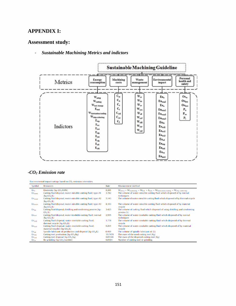
151
151
APPENDIX I:
Assessment study:
- Sustainable Machining Metrics and indictors
-CO2 Emission rate
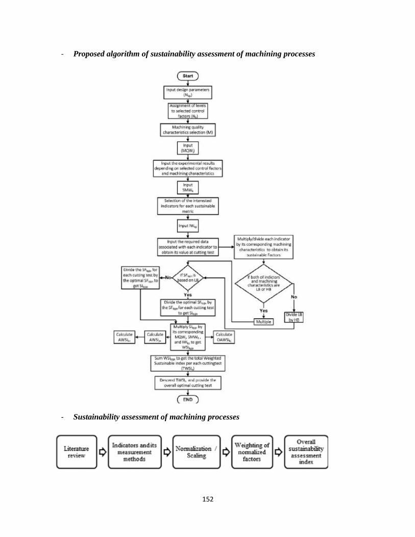
152
152
- Proposed algorithm of sustainability assessment of machining processes
- Sustainability assessment of machining processes
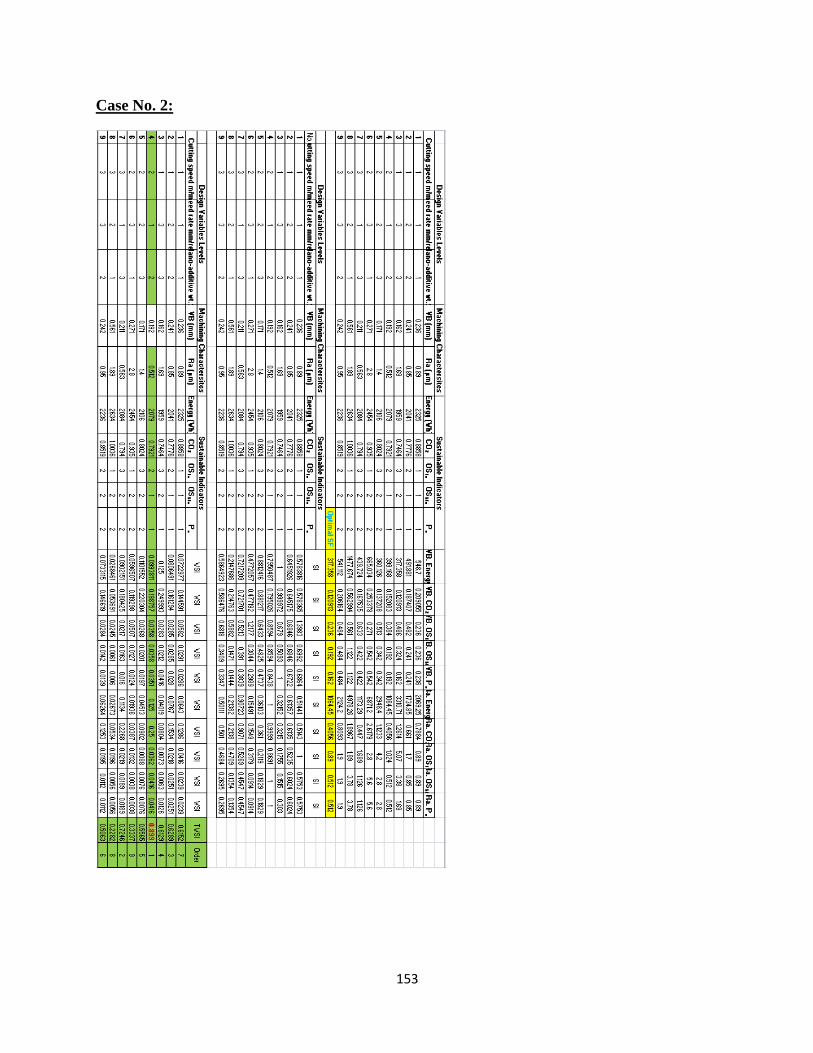
153
153
Case No. 2:
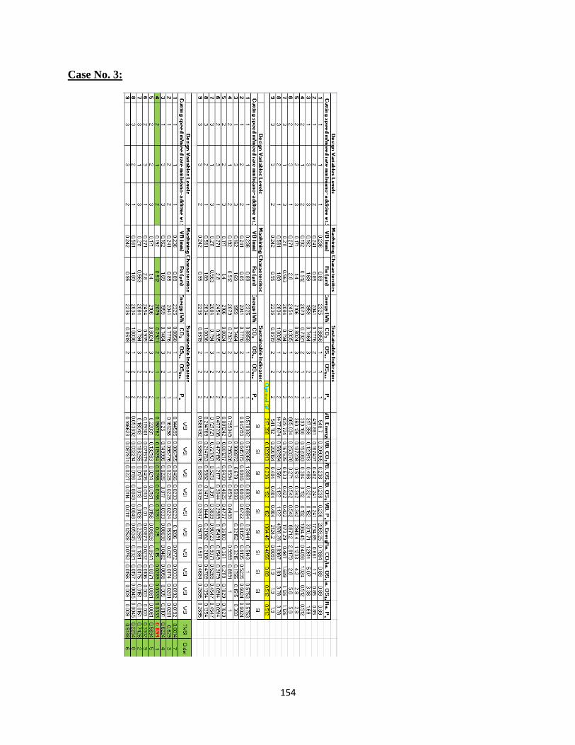
154
154
Case No. 3:
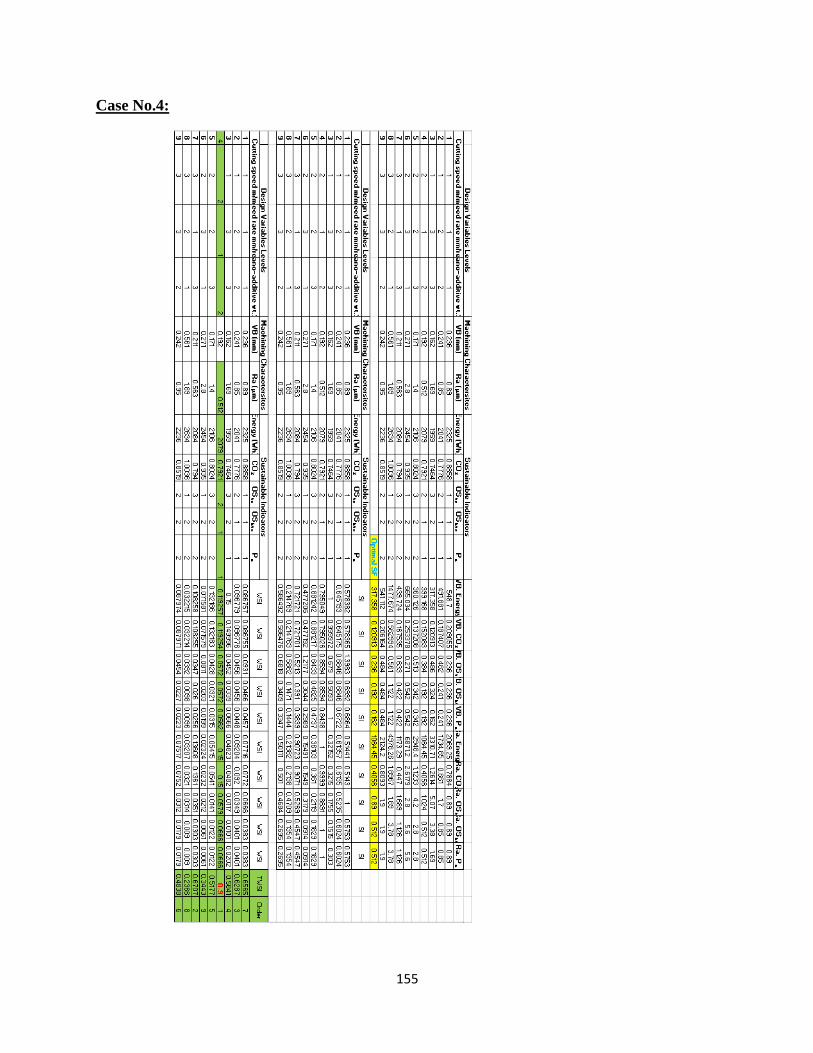
155
155
Case No.4:

156
156
APPENDIX II
Energy model