Embed Size (px)
Citation preview
Proceedings of 4th CIRP International Conference on High Performance Cutting, 2010
Investigation of the Process-Material Interaction in Ultrasonic Assisted Grinding of ZrO2 based Ceramic Materials
B. LAUWERS1, F. BLEICHER2, P. TEN HAAF3, M. VANPARYS1, J. BERNREITER2, T. JACOBS3, J. LOENDERS3
1 K.U.Leuven, Department of Mechanical Engineering, Belgium, [email protected] 2 Vienna University of Technology, Institut für Fertigungstechnik, Vienna, Austria, [email protected]
3 Sirris, Belgium, [email protected]
Abstract: This paper describes a fundamental investigation of the process material interaction (material removal mechanism, surface quality, surface near cracks,..) in the ultrasonic assisted machining of ZrO2. Experiments show that the tool holder system has a significant influence on the obtained amplitude of the vibration. For larger tool vibration amplitudes different material removal mechanisms can be observed. In addition, the vibration of the tool (and/or workpiece) results in more surface craters (near surface cracks) due to material break out. As reported in literature, the vibration also lowers the process force, making it possible to increase the productivity. The paper also presents the development of machining strategies for simple cavities such as holes, slots and pockets. Keywords: Ultrasonic Assisted Grinding, Ceramics, ZrO2, Machining Strategies, Vibration System
1 Introduction
Advanced technical ceramics have a large potential in mechanical engineering, especially for applications where resistance against wear, temperature and chemicals are required. Within this large group of different materials, ZrO2 based ceramics show the largest toughness, making it suitable for mechanical components as well as for mould and die inserts.
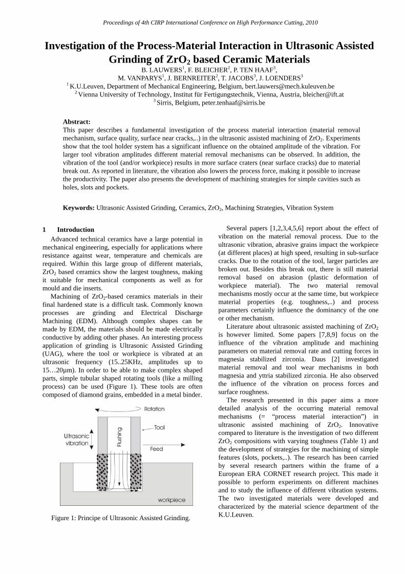
Machining of ZrO2-based ceramics materials in their final hardened state is a difficult task. Commonly known processes are grinding and Electrical Discharge Machining (EDM). Although complex shapes can be made by EDM, the materials should be made electrically conductive by adding other phases. An interesting process application of grinding is Ultrasonic Assisted Grinding (UAG), where the tool or workpiece is vibrated at an ultrasonic frequency (15..25KHz, amplitudes up to 15…20µm). In order to be able to make complex shaped parts, simple tubular shaped rotating tools (like a milling process) can be used (Figure 1). These tools are often composed of diamond grains, embedded in a metal binder.
Figure 1: Principe of Ultrasonic Assisted Grinding.
Several papers [1,2,3,4,5,6] report about the effect of vibration on the material removal process. Due to the ultrasonic vibration, abrasive grains impact the workpiece (at different places) at high speed, resulting in sub-surface cracks. Due to the rotation of the tool, larger particles are broken out. Besides this break out, there is still material removal based on abrasion (plastic deformation of workpiece material). The two material removal mechanisms mostly occur at the same time, but workpiece material properties (e.g. toughness,..) and process parameters certainly influence the dominancy of the one or other mechanism.
Literature about ultrasonic assisted machining of ZrO2 is however limited. Some papers [7,8,9] focus on the influence of the vibration amplitude and machining parameters on material removal rate and cutting forces in magnesia stabilized zirconia. Daus [2] investigated material removal and tool wear mechanisms in both magnesia and yttria stabilized zirconia. He also observed the influence of the vibration on process forces and surface roughness.
The research presented in this paper aims a more detailed analysis of the occurring material removal mechanisms (= “process material interaction”) in ultrasonic assisted machining of ZrO2. Innovative compared to literature is the investigation of two different ZrO2 compositions with varying toughness (Table 1) and the development of strategies for the machining of simple features (slots, pockets,..). The research has been carried by several research partners within the frame of a European ERA CORNET research project. This made it possible to perform experiments on different machines and to study the influence of different vibration systems. The two investigated materials were developed and characterized by the material science department of the K.U.Leuven.
Proceedings of 4th CIRP International Conference on High Performance Cutting, 2010
Table 1: Mechanical properties of used ZrO2. V
aria
nt
Den
sity
[g
/cm
3 ]
E-m
odul
us
[GPa
]
Tou
ghne
ss
[MPa
.m1/
2 ]
Har
dnes
s [k
g/m
m2 ]
TM2 6.02 223 11.1±0.7 1180±13
TM2.5 6.05 203 5.7±1.0 1256±8
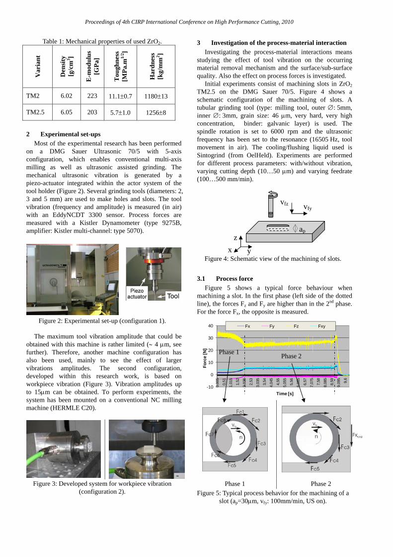
2 Experimental set-ups
Most of the experimental research has been performed on a DMG Sauer Ultrasonic 70/5 with 5-axis configuration, which enables conventional multi-axis milling as well as ultrasonic assisted grinding. The mechanical ultrasonic vibration is generated by a piezo-actuator integrated within the actor system of the tool holder (Figure 2). Several grinding tools (diameters: 2, 3 and 5 mm) are used to make holes and slots. The tool vibration (frequency and amplitude) is measured (in air) with an EddyNCDT 3300 sensor. Process forces are measured with a Kistler Dynamometer (type 9275B, amplifier: Kistler multi-channel: type 5070).
Figure 2: Experimental set-up (configuration 1). The maximum tool vibration amplitude that could be
obtained with this machine is rather limited (∼ 4 μm, see further). Therefore, another machine configuration has also been used, mainly to see the effect of larger vibrations amplitudes. The second configuration, developed within this research work, is based on workpiece vibration (Figure 3). Vibration amplitudes up to 15μm can be obtained. To perform experiments, the system has been mounted on a conventional NC milling machine (HERMLE C20).
Figure 3: Developed system for workpiece vibration
(configuration 2).
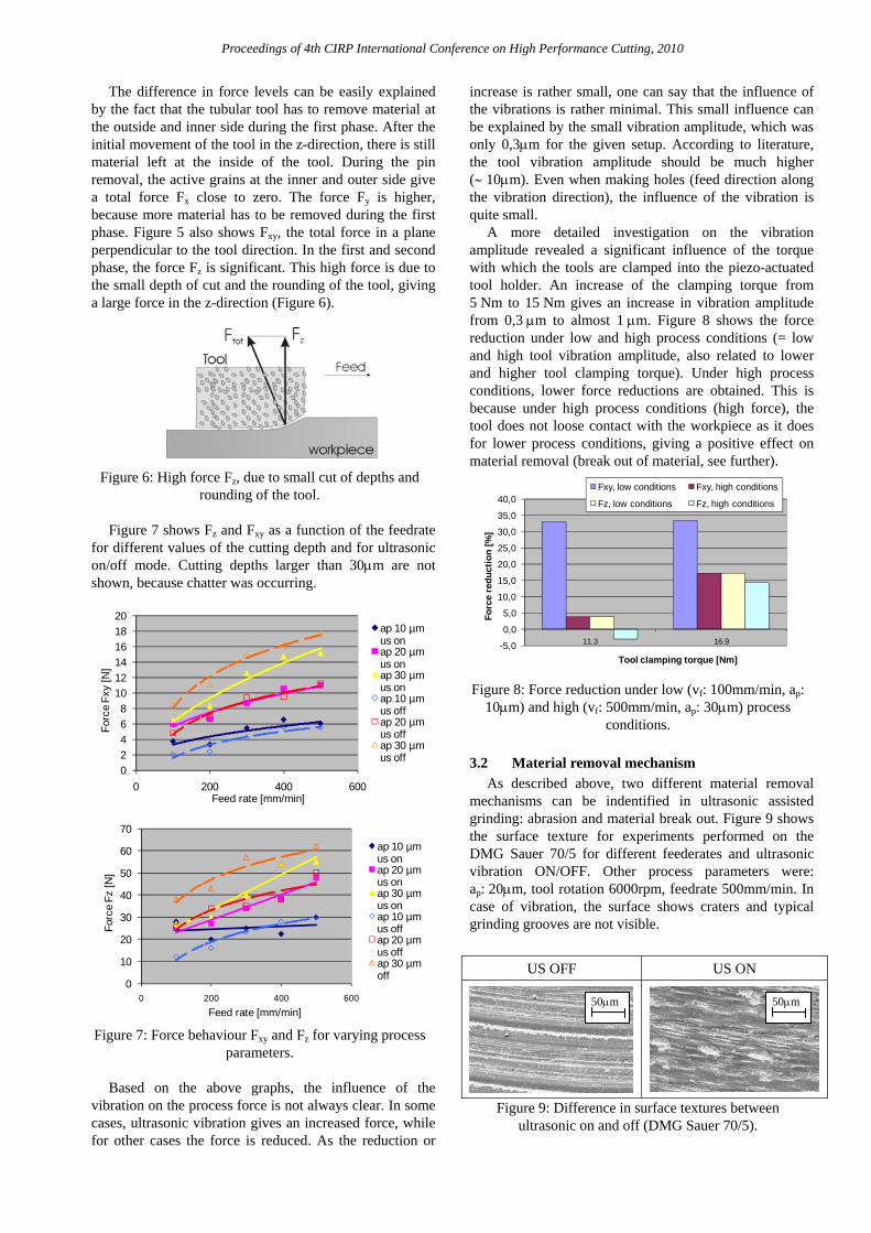
3 Investigation of the process-material interaction Investigating the process-material interactions means
studying the effect of tool vibration on the occurring material removal mechanism and the surface/sub-surface quality. Also the effect on process forces is investigated.
Initial experiments consist of machining slots in ZrO2 TM2.5 on the DMG Sauer 70/5. Figure 4 shows a schematic configuration of the machining of slots. A tubular grinding tool (type: milling tool, outer ∅: 5mm, inner ∅: 3mm, grain size: 46 μm, very hard, very high concentration, binder: galvanic layer) is used. The spindle rotation is set to 6000 rpm and the ultrasonic frequency has been set to the resonance (16505 Hz, tool movement in air). The cooling/flushing liquid used is Sintogrind (from OelHeld). Experiments are performed for different process parameters: with/without vibration, varying cutting depth (10…50 μm) and varying feedrate (100…500 mm/min).
Figure 4: Schematic view of the machining of slots.
3.1 Process force
Figure 5 shows a typical force behaviour when machining a slot. In the first phase (left side of the dotted line), the forces Fz and Fy are higher than in the 2nd phase. For the force Fx, the opposite is measured.
-10
0
10
20
30
40
0,00
5
0,51
1,01
5
1,52
2,02
5
2,53
3,03
5
3,54
4,04
5
4,55
5,05
5
5,56
6,06
5
6,57
7,07
5
7,58
8,08
5
8,59
9,09
5
9,6
Forc
e [N
]
Time [s]
Fx Fy Fz Fxy
Phase 1 Phase 2 Figure 5: Typical process behavior for the machining of a
slot (ap=30μm, vfy: 100mm/min, US on).
vfz vfy
ap z
y x
Phase 1 Phase 2
Proceedings of 4th CIRP International Conference on High Performance Cutting, 2010
The difference in force levels can be easily explained by the fact that the tubular tool has to remove material at the outside and inner side during the first phase. After the initial movement of the tool in the z-direction, there is still material left at the inside of the tool. During the pin removal, the active grains at the inner and outer side give a total force Fx close to zero. The force Fy is higher, because more material has to be removed during the first phase. Figure 5 also shows Fxy, the total force in a plane perpendicular to the tool direction. In the first and second phase, the force Fz is significant. This high force is due to the small depth of cut and the rounding of the tool, giving a large force in the z-direction (Figure 6).
Figure 6: High force Fz, due to small cut of depths and
rounding of the tool. Figure 7 shows Fz and Fxy as a function of the feedrate
for different values of the cutting depth and for ultrasonic on/off mode. Cutting depths larger than 30μm are not shown, because chatter was occurring.
02468
101214161820
0 200 400 600
Forc
e Fx
y [N
]
Feed rate [mm/min]
ap 10 µm us onap 20 µm us onap 30 µm us onap 10 µm us offap 20 µm us offap 30 µm us off
0
10
20
30
40
50
60
70
0 200 400 600
Forc
e Fz
[N]
Feed rate [mm/min]
ap 10 µm us onap 20 µm us onap 30 µm us onap 10 µm us offap 20 µm us offap 30 µm off
Figure 7: Force behaviour Fxy and Fz for varying process
parameters.
Based on the above graphs, the influence of the vibration on the process force is not always clear. In some cases, ultrasonic vibration gives an increased force, while for other cases the force is reduced. As the reduction or
increase is rather small, one can say that the influence of the vibrations is rather minimal. This small influence can be explained by the small vibration amplitude, which was only 0,3μm for the given setup. According to literature, the tool vibration amplitude should be much higher (∼ 10μm). Even when making holes (feed direction along the vibration direction), the influence of the vibration is quite small.
A more detailed investigation on the vibration amplitude revealed a significant influence of the torque with which the tools are clamped into the piezo-actuated tool holder. An increase of the clamping torque from 5 Nm to 15 Nm gives an increase in vibration amplitude from 0,3 μm to almost 1 μm. Figure 8 shows the force reduction under low and high process conditions (= low and high tool vibration amplitude, also related to lower and higher tool clamping torque). Under high process conditions, lower force reductions are obtained. This is because under high process conditions (high force), the tool does not loose contact with the workpiece as it does for lower process conditions, giving a positive effect on material removal (break out of material, see further).
-5,0
0,0
5,0
10,0
15,0
20,0
25,0
30,0
35,0
40,0
11.3 16.9
Forc
e re
duct
ion
[%]
Tool clamping torque [Nm]
Fxy, low conditions Fxy, high conditions
Fz, low conditions Fz, high conditions
Figure 8: Force reduction under low (vf: 100mm/min, ap:
10μm) and high (vf: 500mm/min, ap: 30μm) process conditions.
3.2 Material removal mechanism
As described above, two different material removal mechanisms can be indentified in ultrasonic assisted grinding: abrasion and material break out. Figure 9 shows the surface texture for experiments performed on the DMG Sauer 70/5 for different feederates and ultrasonic vibration ON/OFF. Other process parameters were: ap: 20μm, tool rotation 6000rpm, feedrate 500mm/min. In case of vibration, the surface shows craters and typical grinding grooves are not visible.
US OFF US ON
Figure 9: Difference in surface textures between
ultrasonic on and off (DMG Sauer 70/5).
50μm 50μm
Proceedings of 4th CIRP International Conference on High Performance Cutting, 2010
In order to further investigate the effect of the tool vibration, experiments were also performed on the own developed vibration system (configuration 2). Figure 10 shows the surface textures under the following process conditions: tool (∅: 5mm, grain size: 91µm), ap: 20μm, tool rotation 6000 rpm. There is a clear effect of the vibration visible. Especially under high feedrate conditions, the surface shows a clear break out of material. For a lower feedrate, the surface does not show break out, but the effect of the grain vibration is clearly visible.
US OFF US ON
Vf [
mm
/min
]
100
500
Figure 10: Surface textures under various machining conditions (own developed vibration system).
3.3 Surface quality
The surface roughness of machined samples has been measured on a Taylor-Hobson Form Talysurf – 120L. For the samples machined on the DMG SAUER 70/5, there is a clear effect of the vibration on the surface roughness. Figure 11 shows the surface roughness values for low and high process conditions (same conditions as in Figure 8) for different values of the tool clamping torque. Comparing these conditions with the results described above, it is clear that in cases where the vibration has an effect on the force (high tool clamping torque, low cutting conditions), the difference in surface roughness (ultrasonic mode on/off) is higher.
0,0
0,1
0,2
0,3
0,4
0,5
0,6
0,7
low conditions high conditions
Rou
ghne
ss R
a (µ
m)
11.3 Nm, US off
11.3 Nm, US on
16.9 Nm, US off
16.9 Nm, US on
Figure 11: Effect of the vibration on the surface
roughness (Ra).
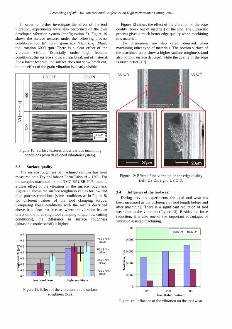
Figure 12 shows the effect of the vibration on the edge quality (break out of material) of the slot. The ultrasonic process gives a much better edge quality when machining this material.
The phenomena are also often observed when machining other type of materials. The bottom surface of the machined parts show a higher surface roughness (and also bottom surface damage), while the quality of the edge is much better [10].
Figure 12: Effect of the vibration on the edge quality (left: US On, right: US Off).
3.4 Influence of the tool wear
During previous experiments, the axial tool wear has been measured as the difference in tool length before and after machining. There is a significant reduction of tool wear due to the vibration (Figure 13). Besides the force reduction, it is also one of the important advantages of vibration assisted machining.
0
0,002
0,004
0,006
0,008
0,01
125 250 500
Tool
wea
r, m
m
Feed Rate [mm/min]
US Off US On
Figure 13: Influence of the vibration on the tool wear.
100μm
Proceedings of 4th CIRP International Conference on High Performance Cutting, 2010
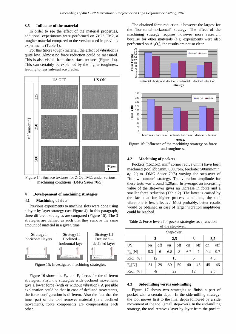
3.5 Influence of the material In order to see the effect of the material properties,
additional experiments were performed on ZrO2 TM2, a tougher material compared to the version used in previous experiments (Table 1).
For this (more tough) material, the effect of vibration is quite low. Almost no force reduction could be measured. This is also visible from the surface textures (Figure 14). This can certainly be explained by the higher toughness, leading to less sub-surface cracks.
US OFF US ON
Vf [
mm
/min
]
125
250
500
Figure 14: Surface textures for ZrO2 TM2, under various machining conditions (DMG Sauer 70/5).
4 Developement of machining strategies 4.1 Machining of slots
Previous experiments to machine slots were done using a layer-by-layer strategy (see Figure 4). In this paragraph, three different strategies are compared (Figure 15). The 3 strategies are defined as such that they remove the same amount of material in a given time.
Strategy I
horizontal layers Strategy II Declined –
horizontal layer
Strategy III Declined –
declined layer
Figure 15: Investigated machining strategies.
Figure 16 shows the Fxy and Fz forces for the different
strategies. First, the strategies with declined movements give a lower force (with or without vibration). A possible explanation could be that in case of declined movements, the force configuration is different. Also the fact that the inner part of the tool removes material (in a declined movement), force components are compensating each other.
The obtained force reduction is however the largest for the “horizontal-horizontal” strategy. The effect of the machining strategy requires however more research, because for other materials (e.g. experiments were also performed on Al2O3), the results are not so clear.
02468
101214161820
horizontal - horizontal declined - horizontal declined - declined
Forc
e Fx
y [N
]
strategy
US Off US On
020406080
100120140160180
horizontal - horizontal declined - horizontal declined - declinedFo
rce
Fz [N
]
strategy
US Off US On
Figure 16: Influence of the machining strategy on force
and roughness.
4.2 Machining of pockets Pockets (15x15x1 mm3, corner radius 6mm) have been
machined (tool ∅: 5mm, 6000rpm, feedrate: 500mm/min, ap: 20μm. DMG Sauer 70/5) varying the step-over of “follow contour” strategy. The vibration amplitude for these tests was around 1.20μm. In average, an increasing value of the step-over gives an increase in force and a smaller force reduction (Table 2). The latter is caused by the fact that for higher process conditions, the tool vibrations is less effective. Most probably, better results would be obtained in case of larger vibration amplitudes could be reached.
Table 2: Force levels for pocket strategies as a function
of the step-over. Step-over
2 2,5 3 3,5 US on off on off on off on off
Fxy [N] 5.3 6 6.8 8 6.7 7 9.4 9.7
Red. [%] 12 15 5 4.5
Fz [N] 31 29 39 50 40 45 45 46
Red. [%] -6 22 12 2.5
4.3 Side-milling versus end-milling
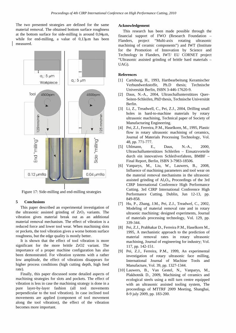
Figure 17 shows two strategies to finish a part of pocket with a certain depth. In the side-milling strategy, the tool moves first to the final depth followed by a side movement of the tool (small step-over). In the end-milling strategy, the tool removes layer by layer from the pocket.
100μm
Proceedings of 4th CIRP International Conference on High Performance Cutting, 2010
The two presented strategies are defined for the same material removal. The obtained bottom surface roughness at the bottom surface for side-milling is around 0,04μm, while for end-milling, a value of 0,13μm has been measured.
Figure 17: Side-milling and end-milling strategies
5 Conclusions
This paper described an experimental investigation of the ultrasonic assisted grinding of ZrO2 variants. The vibration gives material break out as an additional material removal mechanism. The effect of vibration is a reduced force and lower tool wear. When machining slots or pockets, the tool vibration gives a worse bottom surface roughness, but the edge quality is mostly better.
It is shown that the effect of tool vibration is more significant for the more brittle ZrO2 variant. The importance of a proper machine configuration has also been demonstrated. For vibration systems with a rather low amplitude, the effect of vibrations disappears for higher process conditions (high cutting depth, high feed rate).
Finally, this paper discussed some detailed aspects of machining strategies for slots and pockets. The effect of vibration is less in case the machining strategy is done in a pure layer-by-layer fashion (all tool movements perpendicular to the tool vibration). In case inclined tool movements are applied (component of tool movement along the tool vibration), the effect of the vibration becomes more important.
Acknowledgement This research has been made possible through the
financial support of FWO (Research Foundation – Flanders, project “Multi-axis rotating ultrasonic machining of ceramic components”) and IWT (Institute for the Promotion of Innovation by Science and Technology in Flanders, IWT/ EU CORNET project “Ultrasonic assisted grinding of brittle hard materials – UAG). References [1] Cartsburg, H., 1993, Hartbearbeitung Keramischer
Verbundwerkstoffe, Ph.D thesis; Technische Universität Berlin, ISBN 3-446-17620-9.
[2] Daus, N.-A., 2004, Ultraschallunterstützes Quer- Seiten-Schleifen, PhD thesis, Technische Universität Berlin.
[3] Li, Z., Treadwell, C., Pei, Z.J., 2004, Drilling small holes in hard-to-machine materials by rotary ultrasonic machining, Technical paper of Society of Manufacturing Engineering.
[4] Pei, Z.J., Ferreira, P.M., Haselkorn, M., 1995, Plastic flow in rotary ultrasonic machining of ceramics, Journal of Materials Processing Technology, Vol. 48, pp. 771-777.
[5] Uhlmann, E., Daus, N.-A., 2000, Ultraschallunterstützes Schleifen – Einsatzvorteile durch ein innovatives Schleifverfahren, BMBF – Final Report, Berlin, ISBN 3-7983-18506.
[6] Vanparys, M., Liu, W., Lauwers, B., 2008, Influence of machining parameters and tool wear on the material removal mechanisms in the ultrasonic assisted grinding of Al2O3, Proceedings of the 3rd CIRP International Conference High Performance Cutting. 3rd CIRP International Conference High Performance Cutting. Dublin, Jun 12-13, pp. 849-858.
[7] Hu, P., Zhang, J.M., Pei, Z.J., Treadwel, C., 2002, Modeling of material removal rate and in rotary ultraonic machining: designed experiments, Journal of materials processing technology, Vol. 129, pp. 339-344.
[8] Pei, Z.J., Prabhakar D., Ferreira P.M., Haselkorn M., 1995, A mechanistic approach to the prediction of material removal rates in rotary ultrasonic machining, Journal of engineering for industry; Vol. 117, pp. 142-151.
[9] Pei, Z.J., Ferreira, P.M., 1999, An experimental investigation of rotary ultrasonic face milling, International Journal of Machine Tools and Manufacture, Vol. 39, pp. 1327-1344.
[10] Lauwers, B., Van Gestel, N., Vanparys, M., Plakhotnik D., 2009, Machining of ceramics and ecological steels using a mill turn centre equipped with an ultrasonic assisted tooling system, The proceedings of MTTRF 2009 Meeting, Shanghai, 8-9 july 2009, pp. 183-200.