Embed Size (px)
Citation preview

Republic of IRAQ Ministry of Higher Education &Scientific Research Al-Nahrain University /College of Science Department of Physics
Investigation of the Relaibility of Diffusion Bond
Strength Between Ceramic-Metals in Solid State
A THESIS
Submitted to the
Physics Department, College of Science, Al-Nahrain University
In Partial Fulfillment for the Degree of Master of Science in Physics
By
ARWA GHAZI NAGIE AL- TAEE
B.Sc. Physics
Supervised By
Dr. Zareh A. Sarkis Dr. Thamir A. Jumah
Ramadan 1431 August 2010
ACKNOWLEDGMENTSACKNOWLEDGMENTSACKNOWLEDGMENTSACKNOWLEDGMENTS
First of all, profusely and all thanks are due to ALLAH, Lord of the
whole creation work.
It has been a long journey completing this M.Sc. and it would have been
much harder without the assistance of many excellent people. I would
like to thank my supervisors Dr. Zareh A. Sarkis and Dr. Thamir A.
Jabbar for suggestion this project and helping me in accomplishing it.
They have been excellent always available when I needed a help, and
always providing good active.
I would also like to thank the dean of the college of Science Dr. Laith A.
Al-Ani and all the staff of the College of Science in Al-Nahrain
University and specially the staff of the physics department.
I would also like to thank my best supporters Father and mother; Father
gave me some important scientific ideas that help me in the project.
Mother gave me the motive to accomplish the work with full rest.

Contents Page No.
Caption
1-23 Chapter One: Introduction
1 1.1 Bonding of Dissimilar Materials
1 1.1.1 Bonding Interaction Types
2 1.1.2 Bonding Techniques
12 1.2 General properties of ceramic and metal
12 1.2.1 Ceramic
12 1.2.2 Metal
16 1.3 Joint Strength Measurement
17 1.4 Fracture surface characterization
17 1.4.1 Elemental Analysis
18 1.4.2 Phase Identification
19 1.4.3 Microscopic methods
19 1.5 Literature Review
23 1.6 Aim of this work
24-32 Chapter Two: Experimental part
24 2.1 Introduction
24 2.2 Materials

24 2.3 Sample Preparation
24 2.3.1 Ceramic Preparation
25 2.3.2 Ceramic Density and Porosity Measurement
26 2.3.3 Metal Foils
26 2.4 Joining Procedure
29 2.5 Joining tests
39 2.5.1 Tensile Test
39 2.5.2 Microscopic Test
30 2.5.3 Elemental Analysis
31 2.5.4 Phase Identification
33-52 Chapter Three: Results and Discussion
33 3.1 Alumina Density and Porosity
33 3.2 Joining Strength
41 3.3 Elemental Analysis
46 3.4 Optical Microscopic
51 3.5 Phase Identification
53-54 The Conclusions and Future Work
53 4.1 The Conclusions
54 4.2 Future Work
55-60 References

List of Symbols
Definition Symbol
The flux for one place to another place
Coefficient of diffusion D
Concentration gradient dC/dX
Concentration C
Displacement X
Distance between planes d
Geometric factor β
Activation energy qd
Temperature T
Boltzmann constant K
Intensity of characteristic line from element i Ii
Intensity of that line from pure element i I100 i
The weight (W)of the element i Wi
Wave length
Optical microscope OM
X-Ray diffraction XRD
X-ray fluorescence XRF
Time t

Introduction Chapter One
- ١ -
Chapter One
Introduction
1.1 Bonding of Dissimilar Materials
1.1.1 Bonding Interaction Types
Many applications in industry, depends on dissimilar material joints.
Due to the difference in chemical, mechanical and thermal behaviors of
materials, the joining of dissimilar materials presents a challenges,
significantly different than similar materials joining [1]. Bonding as a
subdivision of both solid-state and liquid-phase welding, is a joining
process wherein the principal mechanism is interdiffusion of atoms across
the interface. The bonds is a result of chemical and/or physical interaction
for the two faced materials prepared for joining.
a. Physical interaction: Van der Waals forces include attractions between
atoms, molecules, and surfaces. They differ from covalent and ionic
bonding in that they are caused by correlations in the fluctuating
polarizations of nearby particles (a consequence of quantum dynamics)[2].
Intermolecular forces have four major contributions:
1.A repulsive component resulting from the Pauli exclusion principle
that prevents the collapse of molecules.
2.Attractive or repulsive electrostatic interactions between permanent
charges (in the case of molecular ions), dipoles (in the case of molecules
without inversion center), quadrupoles (all molecules with symmetry
lower than cubic), and in general between permanent multipoles.

Introduction Chapter One
- ٢ -
3.Induction (also known as polarization), which is the attractive
interaction between a permanent multipole on one molecule with an
induced multipole on another.
4.Dispersion , which is the attractive interaction between any pair of
molecules, including non-polar atoms, arising from the interactions of
instantaneous multipoles[2].
b. Chemical interaction: A chemical bond is an attraction between atoms
or molecules and allows the formation of chemical compounds, which
contain two or more atoms. A chemical bond is the attraction caused by
the electromagnetic force between opposing charges, either between
electrons and nuclei, or as the result of a dipole attraction. The strength of
bonds varies considerably; there are "strong bonds" such as covalent and
ionic bonds[3].
c. Mechanical interaction: Stress is a measure of the average force per
unit area of a surface within a deformable body on which internal forces
acts. It is a measure of the intensity of the internal forces acting between
particles of a deformable body across imaginary internal surfaces. These
internal forces are produced between the particles in the body as a
reaction to external forces applied on the body. External forces are either
surface forces or body forces. Because the loaded deformable body is
assumed as a continuum, these internal forces are distributed
continuously within the volume of the material body, i.e., the stress
distribution in the body is expressed as a piecewise continuous function
of space coordinates and time. The SI unit for stress is pascal (symbol
Pa), which is equivalent to one Newton (force) per square meter (unit
area)[4].

Introduction Chapter One
- ٣ -
1.1.2 Bonding Techniques
a. Indirect bonding
1. Diffusion bonding via interlayer
The use of ductile metal interlayer to assist the diffusion bonding of
ceramic (and glasses) to metal can offer several advantages. If the
interlayer is soft, deformation of the metal work pieces is minimal so they
can be bonded in their final forms, and the interlayer is also able to
accommodate some mismatched contraction as the component cool after
being bonded. Further, if the interlayer metal has a modest melting
temperature, it may be possible to bond without degrading the mechanical
properties of heat treatable work piece alloys[5].
2. Soldering
Soldering is a process in which two items (metal, ceramics….etc) are
joined together by melting and flowing a filler metal into the joint, and
the filler metal having a relatively low melting point. Soft soldering is
characterized by the melting point of the filler metal, which is below
400 °C (752 °F). The filler metal used in the process is called solder [6,7].
3. Brazing
Brazing is a joining process whereby a filler metal is heated above
4000C and distributed between two or more close-fitting parts by
capillary action. The filler metal is brought slightly above its melting
(liquids) temperature, while protected by a suitable atmosphere ( usually
a flux). The filler will then flows over the base material in a process
(known as wetting), and then cooled to join the workpieces together. The
structures of metal interlayer diffusion bonding joints and brazed joints
are similar, but the processes involved in their creation are quite different.
Brazing depends on the molten interlayer metal or alloy being able to wet

Introduction Chapter One
- ٤ -
the work pieces. Although metal work pieces are usually readily wetted
by metals, many technologically important ceramics are not special
materials (active to metal brazes) or processes (metallization followed by
brazing using conventional alloys) have to be adopted. Unlike diffusion
bonding, active metal brazing depends on chemical reactions occurring at
metal-ceramic interfaces to promote wettability. Ceramics generally lack
the delocalized electrons that bind together metal lattices[7].
4. Adhesive bonding
An adhesive, or glue, is a mixture in a liquid or semi-liquid state that
adheres or bonds items together. Adhesives may come from either natural
or synthetic sources. The types of materials that can be bonded are vast
but they are especially useful for bonding thin materials. Adhesives cure
(harden) by either evaporating a solvent or by chemical reactions that
occur between two or more constituents[8].
Adhesives are an advantageous for joining thin or dissimilar materials,,
and when a vibration dampening joint is needed. A disadvantage to
adhesives is that they do not form an instantaneous joint, unlike most
other joining processes, because the adhesive needs time to cure[9].
The adhesive bonding of metals is promoted by careful preoxidation
of the metal work piece surface and the presence of components in the
adhesive or primer that can form chemical bridges (such as Fe-O-Si
sequences between steel and polysiloxanes). Thus although polymeric
adhesives have radically different binding characteristics from brazes,
there are some phenomenological similarities in their bonding behavior.
The principle practical attraction of adhesive bonding to the fabricator is
the low temperature at which it can be used, unlike brazing[10].

Introduction Chapter One
- ٥ -
5. Mechanical bonding
The high volume production of joints by crimping, clamping, shrink
fitting, bolting, screwing and other variants makes mechanical
attachments the most widely used joining category for dissimilar
materials combinations. The processes can be cheap and simple to
perform, but the joints lack continuity and in fact demountability is often
a crucial requirement. Mechanical bonding is employed in a wide range
of domestic applications industry[5].
b. Direct bonding
1. Fusion bonding
The ceramic – metal combination could be fusion welded to produce
prototype insulated electrical connectors. The range of ceramic- metal
combination that joined in this way is very small since close matching
of the melting temperature and thermal contraction characteristics is
necessary, if failure by cracking of the brittle ceramic is to be avoided .
These problems could be overcome to some extent by melting
only the bonding face of the metal workpiece, but this is generally
impractical due to the poor ability of liquid metals to wet ceramics[5].
2. Solid state Diffusion bonding
Solid-state diffusion bonding is a process by which two normally flat
interfaces can be joined at an elevate Temperature (about 50%-90% of its
melting point of the parent material) using an applied pressure for a
suitable time.
Diffusion bonding of materials in the solid state is a process for making a
monolithic joint through the formation of bonds at atomic level, as a
result of closure of the mating surfaces due to the local plastic
deformation at elevated temperature which aids inter diffusion at the

Introduction Chapter One
- ٦ -
surface layers of the materials being joined[11]. The aim of diffusion
bonding is to bring the surfaces of the two pieces being joined sufficiently
close that interdiffusion can result in bond formation. However, there are
two major obstacles that need to be overcome in order to achieve
satisfactory diffusion bonds. Firstly, even highly polished surfaces come
into contact only at their asperities and hence the ratio of contacting area
to facing area is very low. Secondly in certain materials, the presence of
oxide layers at the faying surfaces will affect the ease of diffusion
bonding. For some metallic alloys, their oxide films either dissolve in the
bulk of the metal or decompose at the bonding temperature (e.g. those of
many steels, copper, titanium, tantalum, columbium and zirconium). In
practice, because of inevitable surface roughness and also the presence of
oxide layers on most faying surfaces, it is neither feasible to bring
together the surfaces of two pieces within interatomic distances nor to
establish complete metal-to-ceramic contact by simply putting two pieces
together.
For example of diffusion is the motion of vacancy and the doping of
semiconductors, which are used as electronic components. Diffusion
bonding of most metals is conducted in vacuum or in an inert atmosphere
(normally dry nitrogen, argon or helium) in order to reduce detrimental
oxidation of the faying surfaces. Bonding of a few metals which have
oxide films that are thermodynamically unstable at the bonding
temperature (e.g. silver) may be achieved in air[1].
a. Diffusion mechanism
Fig.(1.1) used to illustrate activation energy schematically. A carbon
atom is small (r =0.07 nm) where r is radius of carbon atom and can sit
interstitially among a number of face center cubic (fcc) atoms (such as

Introduction Chapter One
- ٧ -
iron atom). If it has enough energy it can squeeze between the iron atoms,
to the next interstice when it vibrates in that direction, at 200 C. There is
only a small probability that it will have that much energy. At higher
temperature the probability increases. The other diffusion mechanism
(interstitial) is sketched in fig(1.2). When all the atoms are the same size,
or nearly so the vacancy mechanism becomes predominant. The vacancy
may be present either as part of defect structure or because of extensive
thermal agitation[12].
Figure (1.1): Atom movement[12]
Figure (1.2): Diffusion mechanism. (a) By vacancies. (b) By Interstitialcies[12]
Solid state diffusion can be mathematically described by two differential
equations which are called Fick,s first and second laws.
Fick's first law can be express from this relation:
Introduction Chapter One
- ٨ -
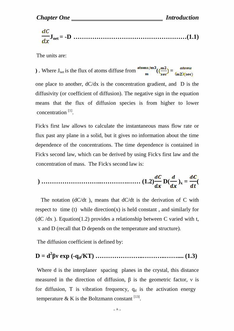
………………………………………………(1.1) Jnet = -D
The units are:
= () . Where Jnet is the flux of atoms diffuse from
one place to another, dC/dx is the concentration gradient, and D is the
diffusivity (or coefficient of diffusion). The negative sign in the equation
means that the flux of diffusion species is from higher to lower
concentration [1].
Fick,s first law allows to calculate the instantaneous mass flow rate or
flux past any plane in a solid, but it gives no information about the time
dependence of the concentrations. The time dependence is contained in
Fick,s second law, which can be derived by using Fick,s first law and the
concentration of mass. The Fick,s second law is:
( )x = D( ) ………………………..………….…… (1.2)
The notation (dC/dt )x means that dC/dt is the derivation of C with
respect to time (t) while direction(x) is held constant , and similarly for
(dC /dx ). Equation(1.2) provides a relationship between C varied with t,
x and D (recall that D depends on the temperature and structure).
The diffusion coefficient is defined by:
D = d2βν exp (-qd/KT) ……………… …..………..…….... (1.3)
Where d is the interplaner spacing planes in the crystal, this distance
measured in the direction of diffusion, β is the geometric factor, ν is
vibration frequency, qd is the activation energy for diffusion, T is
temperature & K is the Boltzmann constant [13].

Introduction Chapter One
- ٩ -
Depending on the equation (1.2) the diffusivity varies with many
important factors:
1. The nature of the solute atoms.
2. Nature of solid structure.
3. Higher temperatures provide higher diffusivities, because the atoms
has higher thermal energies and therefor greater probabilities of being
activated over the energy barrier between atoms.
4. The grain size of metal effect on the diffusivity for example Carbon
atoms have a higher diffusivity in ceramic than do nickel atoms in
ceramic because the carbon atom is small one.
5. Copper atoms diffuse more readily in aluminum than in copper because
the cu-cu bonds are stronger than the Al-Al bonds (as evidenced by their
melting temperature).
6. Atom has higher diffusivity in bcc iron than in fcc iron because the
former has a lower atomic packing factor (0.68 versus 0.74) and the fcc
structure has larger interstitial holes; however, the passageways between
the holes are smaller in the fcc than in the bcc structure [13].
b. Advantages of solid-state diffusion bonding
The advantages of solid-state diffusion bonding can be summarized as
follows[5]:-
1. The process has the ability to produce high quality joints so that neither
metallurgical discontinuities nor porosity exist across the interface. The
optical micrograph of diffusion bonding of cobalt-base super alloy was
shown in fig.(1.3).

Introduction Chapter One
- ١٠ -
Fig (1.3) Optical micrograph of the diffusion bond in a cobalt-base super alloy,
free from flaws, voids and loss of alloying elements[14]
2. Joining of dissimilar materials with different thermo-physical
characteristics, which is not possible by other processes, may be achieved
by diffusion bonding. Metals, alloys, ceramics and powder metallurgy
products have been joined by diffusion bonding. Fig.(1.4) shows
dissimilar bonds in different Al alloy and Ti alloy tested by bending and
torsion tests. No preferential failure at the joint interfaces occurred.
Fig. (1.4) Bonding of different alloys of Al and Ti[14]
3. High precision components with complicated shapes or cross sections
can be manufactured without subsequent machining. This means that
good dimensional tolerances for the products can be attained.
4. Apart from the initial investment, the consumable costs of diffusion
bonding are relatively low as no expensive solder, electrodes, or flux are

Introduction Chapter One
- ١١ -
required (although the capital costs and the costs associated with heating
for relatively long times may be high).
5. Diffusion bonding is free from ultraviolet radiation and gas emission so
there is no direct bad effect on the environment health and safety
standards are maintained[14].
c. Limitations of diffusion bonding
Diffusion bonding has many limitations, and among them are the
following[11,5]:-
1. Great care is required in the surface preparation stage. Excessive
oxidation or contamination of the faying surfaces would decrease the
joint strength drastically. Diffusion bonding of materials with stable oxide
layers is very difficult. Production of thoroughly flat surfaces and also
precise fitting-up of the mating parts takes a longer time than with
conventional welding processes.
2. The initial investment is fairly high, and production of large
components is limited by the size of the bonding equipment used.
3. The suitability of this process for mass production is questionable,
particularly because of the long bonding times involved[5].
d. Problems with solid-state diffusion bonding
The aim in diffusion bonding is to bring the surfaces of the two pieces
being joined sufficiently close that inter diffusion can result in bond
formation. There are two major obstacles that need to be overcome in
order to achieve satisfactory diffusion bonds[11]:-
1. Even highly polished surfaces come into contact only at their asperities
and hence the ratio of contacting area to faying area is very low.

Introduction Chapter One
- ١٢ -
2. In most metals, the presence of oxide layers at the faying surfaces will
affect the ease of diffusion bonding [11].
1.2 General properties of ceramic and metal
Ceramics and metals used in joined samples specified with many
important mechanical and thermal properties.
1.2.1 Ceramic:
A ceramic material is often understood as restricted to inorganic
crystalline oxide material. It is solid and inert. Ceramic materials are
brittle, hard, strong in compression, weak in shearing and tension. They
withstand chemical erosion that occurs in other materials subjected to
acidic or caustic environment. Ceramics(Al2O3) generally can withstand
very high temperatures such as temperatures that range from 1,000 °C to
1,600 °C. The specific properties of ceramic material are high mechanical
strength, wide range of thermal expansion, stability of geometric shapes,
accuracy of their dimensions, no special annealing required and low
vapor pressure at high temperatures. One of common types of ceramics is
alumina which represents about 25% of the earth crust and used in this
research. Pure alumina (α-alumina) is poly – crystalline material, has a
hexagonal structure with two Al2O3 molecules per unit cell[15,16].
1.2.2 Metal:
Metal in joined samples can be as a structure or as a joining means. In
any case the important physical properties for joining are:-
a. Melting points:
Metals tend to have high melting points because of the strength of the
metallic bond. The strength of the metallic bond varies from metal to

Introduction Chapter One
- ١٣ -
metal and depends on the number of electrons in each atom delocalises
into the sea of electrons, and on the packing[1].
1. Metals like sodium and potassium have relatively low melting points
mainly because each atom only has one electron to contribute to the bond.
2. Elements are also inefficiently packed (8-co-ordinated), so that they
aren't forming as many bonds as most metals.
They have relatively large atoms (meaning that the nuclei are some
distance from the delocalised electrons) which also weakens the bond[12].
b. Thermal conductivity:
Metals are good conductors of heat. Heat energy is picked up by the
electrons as additional kinetic energy (it makes them move faster). The
energy is transferred throughout the rest of the metal by the moving
electrons[13].
c. Malleability and ductility:
Metals are described as malleable (can be beaten into sheets) and ductile
(can be pulled out into wires). This is because of the ability of the atoms
to roll over each other into new positions without breaking the metallic
bond. If a small stress is put onto the metal, the layers of atoms will start
to roll over each other. If the stress is released again, they will fall back to
their original positions, as shown in fig.(1.5). Under these circumstances,
the metal is said to be elastic[13].

Introduction Chapter One
- ١٤ -
Fig.(1.5) Small stress put on the metal[13]
If a larger stress is put on, the atoms roll over each other into a new
position, and the metal is permanently changed, as shown in fig.(1.6).
Fig.(1.6)Large stress put on the metal[13]
d. The hardness of metals:
The rolling of layers of atoms over each other is hindered by grain
boundaries because the rows of atoms don't line up properly. It follows
that the more grain boundaries there are (the smaller the individual crystal
grains), the harder the metal becomes.
Offsetting this, because the grain boundaries are areas where the atoms
aren't in such good contact with each other, metals tend to fracture at
grain boundaries. Increasing the number of grain boundaries not only
makes the metal harder, but also makes it more brittle[1].
e. Controlling the size of the crystal grains
If a pure piece of metal is present then one can control the size of the
grains by heat treatment or by working the metal. Heating a metal tends
to shake the atoms into a more regular arrangement, decreasing the

Introduction Chapter One
- ١٥ -
number of grain boundaries, and so making the metal softer. Banging the
metal around when it is cold tends to produce lots of small grains. Cold
working therefore makes a metal harder. To restore its workability,
reheating were needed. The regular arrangement of the atoms can be
breakup by inserting atoms of a slightly different size into the structure.
Alloys such as brass (a mixture of copper and zinc) are harder than the
original metals because the irregularity in the structure helps to stop rows
of atoms from slipping over each other[6]. Table (1.1) shows some
properties of metals and alumina.
Table (1.1) Material properties[1,10,13]
Atomic radius
(Pm)
Thermal
expansion x10-6
(K -1)
Melting point (0C)
Density
(g/cm3)
Mass number
(A)
Atomic number
(Z)
Sample
128 16.5 1084 8.9 ٦٤ 29 Cu
144 18.9 962 10.49 ١٠٨ 47 Ag
143 23.1 660 2.7 ٢٧ 13 Al
134 30.2 420 7.14 ٦٥ 30 Zn
175 28.9 327 11.4 ٢٠٧ 82 Pb
140 22 ٢٣٢ 7.3 119 50 Sn
- 8.2 ٢٠٤٠ 3.98 - - Al 2O3
1.3 Joint Strength Measurement
The joint strength, as the most important property of the joint can be
characterized by the use of fracture mechanics. The strength of the joint

Introduction Chapter One
- ١٦ -
system can be define as the amount of energy necessary to separate the
ceramic from metal at the interface in the form of an applied load . The
application of the load is either a tensile or a shear stress.
In tensile stress, the applied force will be normal to the interface, while
in shear stress the applied force is parallel to the interface. Figure (1.7)
shows the basic principles of this stress type[17].
There are three major requirements for a testing method, shear or
tensile stress to evaluate the mechanical properties of ceramic –metal
joint. First a testing method should lead to accurate and consistent results.
Second a testing method to be able to evaluate effects of processing
variables on the joint properties. Third, the result of the test should
provide meaningful engineering parameters that can be utilized for
designing the ceramic-metal joints[18].
Fig (1.7) Types of stresses in ceramic to metal joint A-Tensile stress B- Shear
stress[3]
1.4 Fracture surface characterization
The fractured surfaces can be examined by X-ray methods [elemental
analysis by using X-ray fluorescence (XRF), phase identifications by
using X-ray diffraction (XRD)], and microscopic methods using optical
microscope (OM).

Introduction Chapter One
- ١٧ -
1.4.1 Elemental Analysis:
The X-Ray fluorescence spectrometry is the best technique to give rapid
information about qualitative and quantitative elemental analysis. Having
made the qualitative survey on material, quantitative evaluation of
concentrations can be made by reducing the net intensity of specific X-
ray lines (K-lines) characteristic of the element to mass concentrations.
After intensity correction for background, the ratio of intensities for a
given line from the sample and pure standard element is directly
proportional to the weight per unit area of the element in the spacemen
being analyzed[19]. If I i be the intensity of characteristic line from element
i in the sample and I100i be the intensity of the line from pure element i.
Then (Wi/a) which is the weight (W) per unit area (a) of the element i in
the sample will be given by[20]:-
I/I 100i=Wi/a ……………………………………….……….. (1.4)
This equation shows that the analytic line intensity Ii from material layer
is linearly related to the weight of the element in the sample (Wi/a). If we
are dealing with a three-component mixture, (for example), then:
W i + Wj +Wk =100%=1 …………………………………. (1.5)
And a relative intensity Ri of an element in the sample is given by:
Ri=I i /I100i ………………………………………………… (1.6)
Where i, j and k are the elements in the sample. For multi-elements, the
interfering effects are present; and fluorescent intensity can depart widely
from proportionality due to the amount present of other elements. These
effects are either absorption effects or enhancement effects [21,22,23], and
will have a special mathematical treatments and experimental
calibrations[24].

Introduction Chapter One
- ١٨ -
1.4.2 Phase Identification:
X-ray diffraction technique is a powerful tool for investigating the solid
state phases [20]. Suppose the monochromatic X-ray are directed towords a
crystal and a parallel beam which interacts with all atoms in the region of
the crystal to which it can penetrate. The additional path traversed is
2d Sinθ for a ray which suffers specular reflection from the second plane
rather than the first. All specular reflected components will be able to
combine constructively in phase if this distance is a multiple of
wavelength (). Thus the condition for efficient specular reflection
(Bragg, s law) is:
2d Sinθ = n ………………………..…………………….. (1.7)
Where n is an integer. Useful information is provided by the peak, s
characteristic [21,22]:-
1. Position: The position of the peak, measured as the angle θ.
2. Intensity: the relative intensity of the peaks, measured either as the
peak height or more correctly, as the area under its profile.
3. Shape: The shape of the peak, of which its breadth is a useful guide,
provides information regarding crystallite size and lattice imperfections,
including strain [23].
1.4.3 Microscopic methods:
The optical microscopic technique provides a direct and easy method for
examining fractured surfaces and to determine its morphology providing
a good method for dimension measuring method down to the wavelength
of visible light [24].

Introduction Chapter One
- ١٩ -
1.5 Literature Review
Due to industrial requirements for joining of the dissimilar materials
such as ceramic to metal or alloy, in 1920 many researcher had been
investigate the capability of joining[16,25]. The Diffusion Hypothesis was
the most commonly accepted hypothesis, considers the contribution of
interatomic diffusion during bond formation [26] .The difference in the
energy level of surface atoms and of bulk atoms is the basis of this
hypothesis. All attempts at modelling diffusion bonding have two main
aims. The first is to optimize the process variables e.g. surface finish,
bonding temperature, pressure and time so that the proper bonding
conditions for a particular material can be identified. Secondly, a model
attempts to obtain a reasonable and profound understanding of the
mechanisms involved and their relative contributions not only for
different bonding conditions but also for different materials being
joined[27].
The realization of joining ceramic to metal date back to 1934 when
Siemens, et.al. at Telefunken, and Allgemenine in Germany [16,28]
independently began to develop ceramic sealing techniques. In 1953
King, et.al., were expected that the migration of interface away from the
voids was assumed to occur during the second stage and remaining
isolated voids were removed by volume diffusion in the third stage [29] .
In 1966 Cline[9] was reach to the same results of King, he found two stag
models assuming localized plastic deformation followed by the diffusion
controlled process using the recrystalization model of parks.
In 1975 Garmong , et.al.[30], study the effects of corresponding
wavelength and roughness of the joining surface removable of the voids
was modulated by using the center equations derived by Coble in1970.

Introduction Chapter One
- ٢٠ -
In 1982, Derby et.al.[8], an intensive sintering equations assuming six
different diffusion mechanisms, and makes a modification on the existing
model in order to reduce the discontinuity in bonding rate, especially
between the second and final stage.
In 1986 Borbidge , et.al. [31], were discussed the bonding between wide
range of materials , metals (such as steel, copper, Titanium, Platinum and
Gold), and ceramics Al2O3 and silicon nitride. They concluded that the
reaction bonding of solid state process can be used to join a wide variety
of ceramics to metals, and the interlayer of suitable metals can be used to
facilitate bonding in those cases.
In 1989 various techniques were developed in order to obtained the best
bond in ceramic to metal interface, and have been discussed by M. G.
Nicholas, et.al.[32], and Mamora N. et.al. [33].
In 1990 Nakamura, et.al. [34], were studied the solid state bonding of
silicon nitride ceramic with nickel chromium alloy interlayer. Joining was
performed by hot pressing between 10000C and 13500C ( in argon), under
uniaxial pressure in the range of 50 to 100 MPa. They found the
formation of the interfacial poress (which not distributed uniformly at the
bond interface), the scatter in strength is relatively large.
In 1992 C.D. Qin, et.al. [35], were studied a diffusion bonds of Ni/ZrO2
and Ni /NiO2 /ZrO2 . They found that subsequent annealing in air after
bonding improves bond strength and annealing in vacuum reduced
strength. This attributed to the formation of thin oxide layer during
annealing in air which enhances adhesion to the ceramic, where as
annealing in vacuum creates de bonding voids at the spaceman edges.
Introduction Chapter One
- ٢١ -
In the same year Crank J.[30] and Bernard Y. [36], were studied joining of
ceramic to metal based on three main features compatibility of thermal
expansion coefficient for the parts to be joint.
In 1999 Irfan, et.al.[37], were studied the joint of copper and aluminum
materials coupled by diffusion and friction welding methods, which are
able to weld in a solid state without melting. This study was showed that
the intermetallic phases (Al2Cu, AlCu, Al4Cu9) occurred during the
welding processes which have very important effects on the joint
mechanical properties. As a result of diffusion welding process which
takes long time and outer appearance of welding place is more uniform,
the strength of the bonding zone is lower than of that pure aluminum.
In 2000 Sarkis, et.al.[38], were studied solid state diffusion bonding of
metals to ceramic and they concluded that the bonding due to chemical
interaction between the metal and the ceramic is found to be unlikely and
the braking strength of the metal-ceramic joint showed a linear relation
with the melting point of metals involved.
In 2001 A. A Shirzadi, et.al[39], worked to overcome problems with
surface oxides, when joining alumina with different alloys and compared
for both solid state diffusion bonding and conventional transient liquid
phase(TLP) diffusion bonding.
In the same year Jasenka , et.al.[37], were determined whether the rate of
cooling induced structural changes in a high gold alloy and/or whether
these changes modified the bond strength between the gold alloy and
hydrothermal ceramic. Analysis of variance joints reveled no
(statistically) significant difference in bond strength among the three
types of specimens, suggesting that the mode of alloy cooling had no
substantial effect either on the microstructure of high gold alloy or on the

Introduction Chapter One
- ٢٢ -
quality of bond between gold alloy and hydrothermal ceramic.
In 2008[40] a diffusion bonding method has been developed that enable
large transfer of single crystal lithium niobate thin film to silicon
substrates. Transmission electron microscopy confirms the interface
evaluation via diffusion bonding which combines interfacial diffusion.
Many authors[41,42] have studied the fracture surface characterization and
microcraking behavior at elevated temperatures. Advanced technologies
were used to evaluate properties and analyze the joint strength. Different
methods of test provides important information about the mechanical
properties of the joint which were well established in many
references[40,43,44,].Fracture surfaces were analyzed using optical
microscope (OM), for studying microstructures and examining the
interface layers [35,17].

Introduction Chapter One
- ٢٣ -
1.6 Aim of this work
The purpose of this study was to evaluate the diffusion bonding in solid
state at a contact surfaces between alumina and submitted pure metals Cu,
Ag, Al, Zn , Pb, and Sn. For achieving this process, tensile fracture test
was carried out for conducting the reliable of joint strength. Fracture
surfaces were attempted by X-ray methods listed below:
a. Elemental analysis using X-ray fluorescence (XRF).
b. Phase identification using X-ray diffraction (XRD).
The fractured surfaces were examined microscopically by using optical
microscope (OM).

Chapter Two
Experimental part
٢٤
Chapter Two
Experimental Part
2.1 Introduction
This chapter deals with procedure of samples preparation (cutting, polishing and
decontamination processes), joining processes and hence investigation of bond
strength. Fracture surface identifications were achieved by using a non- destructive
methods such as X-Ray (XRF,XRD) and microscope techniques.
2.2 Materials
The materials used in this investigation were; metals such as Sn, Pb, Zn, Al, Ag,
and Cu, while the ceramic was alumina (Al2O3).
High purity metals were used as a thin foils (99.9 wt% purity). Polycrystalline α-
alumina (99.8 wt% purity and 25µm of average particle size) were used in preparing
the joined samples.
2.3 Sample Preparation
2.3.1 Ceramic Preparation
All ceramic samples were prepared from alumina (Al2O3), and cutted by diamond
cutter machine into rectangular shape (dimensions of (1x1x0.5) cm3). To get normally
flat surface and free of obstacles, wet grinding and polishing of all samples were
achieved(to obtain the proper surface). The grinding and polishing processes were
carried out on alumina parts as follows:

Chapter Two
Experimental part
٢٥
a. Grinding stage: The alumina was wet grind by silicon carbide metallographic
papers with different grads of 360, 800, and 1000 respectively. Distilled water was
used as a cooler to avoid any possibilities of cracking in alumina samples.
b. Polishing stage: The alumina samples were polished by using special cloth with
diamond paste. These two stages were done using Strues machine of Denmark made.
In order to obtain clean alumina surface, it was necessary to remove any
contaminated materials (such as greasing), chemical cleaning were conducted by
immersing the alumina pieces in acetone for 20 minutes followed by immersing in
dilute nitric acid for five minutes and subsequent rinsing in distilled water. Finally the
alumina pieces were fired in air at temperature 1000 0C for about one hour, the
samples were kept in a desiccator ready to use, as it is recommended by some
researcher [3,18,45].
2.3.2 Ceramic Density and Porosity Measurement
A preliminary tests for measuring the density and porosity for the prepared alumina
samples have been performed according to ASTM-C373-88. The bulk density (ρ) is
defined as the following equation[46]:
ρ =Dr/(W-S)…………………………….…………..………….….…(2.1)
Where:
Dr = dry weight in (gm)
S = suspended weight in (gm)
W = saturated weight in (gm)
On the other hand the apparent porosity as percentage (p) is defined as in the
following equation[47]:

Chapter Two
Experimental part
٢٦
P= [(W-Dr)/V]x 100 …………………………………..…………..….(2.2)
Where V is the exterior volume in cm3. The accuracy of measuring density and hence
the porosity was within ± 2%.
2.3.3 Metal Foils
The high purity metals (99.9 wt%) of 1mm thick rolled foils were prepared into
square dimensions similar to that alumina(1x1x0.5) cm3 of dimension (1x1x0.1) cm3.
The metals surfaces were prepared to joining by immersing it for about 30 minutes in
acetone followed by polishing until it is visually seen to be free of oxide. The sheets
were then kept in a desiccator ready to use.
The selection of metals were mainly according to their melting points. A wide range
were chosen from Sn up to Cu (see table (1.1).
2.4 Joining Procedure
Metal foils were inserted between two pieces of alumina and fixed by a fixture of
stainless-steel. Figure(2.1) represents the fixture set up.

Chapter Two
Experimental part
٢٧
Fig. (2.1) Joining Fixture Set up
Pressure was then applied by torque-spanner with value (3x10⁵ Pa). The pressure is
equally distributed on each side of the fixture. To reduce the metal oxidation process,
the assembly was embedded in alumina powder in order to isolate the joining set up
from the ambient conditions as it is illustrated in figs. 2.2,a and b.
(a) Before isolation

Chapter Two
Experimental part
٢٨
(b) After isolation
Fig.(2.2) Joining Set up preparations
The system to be joined was fixed in the center of the furnace chamber and then
heated to about 0.9Tm (where Tm is the melting point of each metals) under
atmospheric condition. For this purpose Qallenhamp furnace( made in England) was
used. The soaking time were two hours. The joining assembly was allowed to cool
down in the same way of heating schedule as shown in fig.(2.3).The final step was the
carefully pressure released from the sample. Fig.(2.4) shows a typical joined sample.
Fig. (2.3) Time-Temperature joining schedule

Chapter Two
Experimental part
٢٩
Fig.(2.4) Joined sample
Some tried experiments were performed to select the best soaking time starting 0.5
hr up to 2.5 hr. Joining temperature (starting from 0.5 Tm up to 0.9 Tm). Experiments
revels that 2 hr for 0.9 Tm were convenient, since a suitable bond were achived.
2.5 Joining tests
2.5.1 Tensile Test
Measurement of the joint strength was carried out by using a tensile machine
TINIUSOLSEN , with XP computer, made in England. The tensile force was
applied at the crosshead speed of 3 mm/min. A suitable designed fixture (as
shown in fig.(2.5)) was used to hold the alumina- metal assembly on the tester
machine. The fracture stress in (N/m2=Pa) was calculated from the force at
fracture point of this assembly measured in Newton (N) , divided by fracture
surface area (m2).

Chapter Two
Experimental part
٣٠
Fig. (2.5) Joining sample under test.
2.5.2 Microscopic Test
The fracture surfaces were examined using optical microscope at 50-1000
magnification. For this purpose Nikon optical microscope fitted by camera digital
Nikon with XP computer, made in Japan, was used to achieve these tests. Fig.(2.6)
show the optical microscope instrument used to carry out these testes.
Fig.(2.6) Optical microscope used in this investigation

Chapter Two
Experimental part
٣١
2.5.3 Elemental Analysis
X-ray Fluorescence (XRF) instrument type wave length dispersive X-ray
Fluorescence(WLDXRF) work by exposing a sample to a beam of X-rays from
tungsten target. The qualitative analysis of materials have been carried out by using
this spectrometry of Twin-X-simple, Oxford instrument as shown in fig.(2.7), with the
following operation conditions:
1.X-ray tube target = Tungsten
2.Power =50 kV, 1mA, 250 W
3.Cone angle =250
4.Vacuum =10-3 mbar
The atoms of the sample absorb the X- ray energy and become temporarily excited
and then emits secondary X-rays. Each element emits x-rays at a unique
energy, known as characteristic energy of the emitted element. An XRF analyzer can
provide qualitative and quantitative analysis regarding the composition of the material
being tested. Elemental composition can be determined by making use of calibration
curves between intensity in count per second (CPS) and the composition.

Chapter Two
Experimental part
٣٢
Fig (2.7) WDXRF instrument (Twin-X-simple)
2.5.4 Phase Identification
A typical X-ray diffraction tests were conducted for phase identification of all
materials used for joining process and fractured surfaces to detect any changes in the
joined samples. The phase identification were carried out by using Lab. XRD-6000,
SHIMADZU, (made in Japan) machine as shown in fig.(2.8). Copper is the X-ray
tube target with monochrometer ( Kα1 radiation) operate at 40kV and 30 mA. The 2Ɵ
rang was taken from 200 up to 600. The rang limit was taken according to the basic
informations for each element in this study.
Chapter Two
Experimental part
٣٣
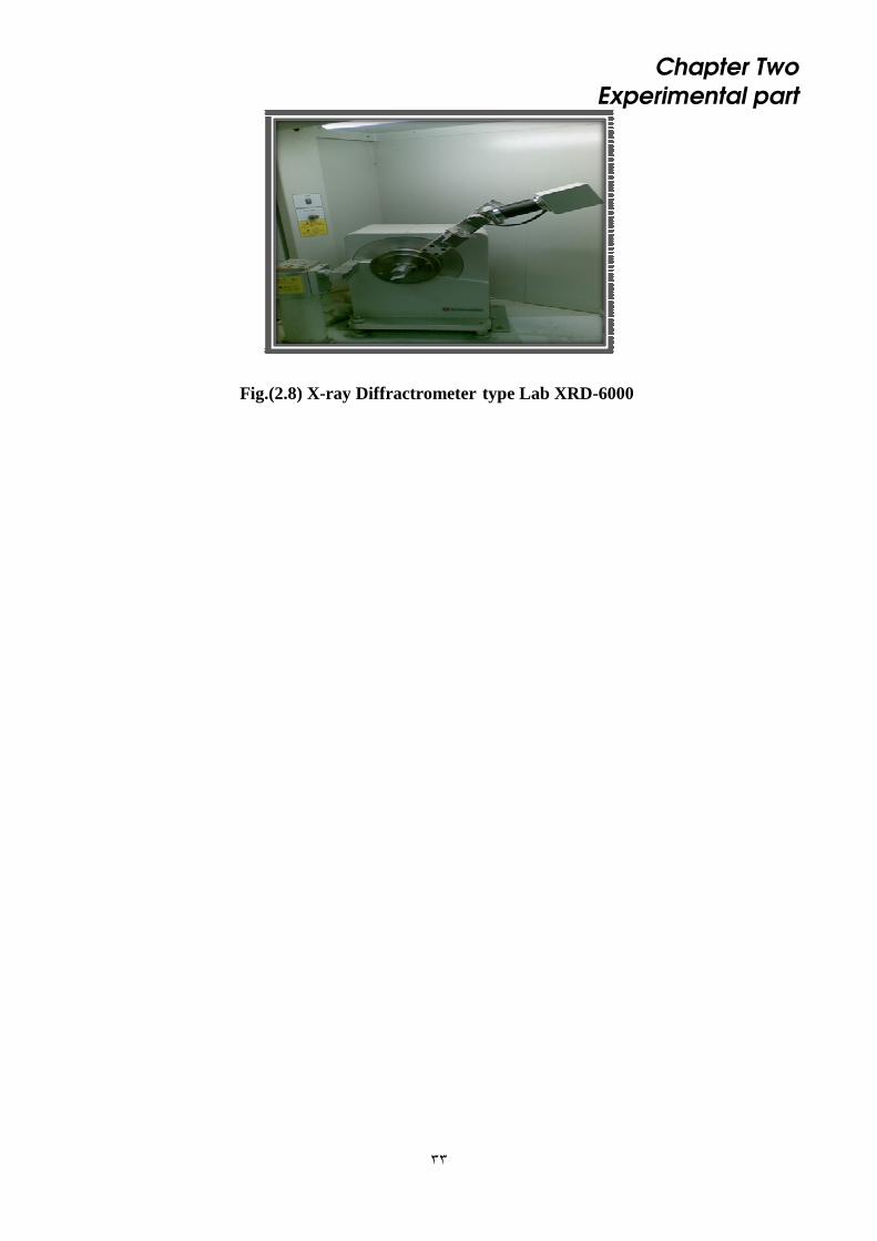
Fig.(2.8) X-ray Diffractrometer type Lab XRD-6000

ts and DiscussionResul Chapter Three
٣٣
Chapter Three
Results and Discussion
3.1 Alumina Density and Porosity
The density and porosity of alumina which is used in this investigation
were calculated according to equations (2.1)and (2.2) respectively. The
results were listed in table (3.1).
Table (3.1) Alumina density and porosity results
The benefit of the porosity of alumina is may be for introduce the
interlocking bonds and enhances the diffusivity of metal atoms through
alumina.
3.2 Joining Strength
Typical tensile tests results were illustrated in fig.(3.1) which shows the
maximum joining strength (applied force per unit area necessary to separate
the joint faces) with the extension in (mm).
porosity % Density g/cm3 Sintering temp.(οC) Ceramic
4.03 3.82 1650 Al2O3

ts and DiscussionResul Chapter Three
٣٤
Fig. (3.1)Typical Tensile tests for metals bonded to alumina.

ts and DiscussionResul Chapter Three
٣٥
This separation needs a different forces for the different metals, even the
whole samples were carried out at the same initial conditions as mentioned in
chapter two. Table (3.2) represents fracture strength for all ceramic metals
joined samples at 0.9 of its melting temperature.
Table (3.2)Fracture strength for ceramic-metals joined samples at bonding pressure
of 0.3 MPa and 2hr socking time
Bonding
Catoagoria
Bonding
Strength
x104Pa(N/m2)
Bonding Temp.
(≈0.9 Tm0C)
10
Metal
weak Nill 900 Cu
Strong 86.5 864 Ag
weak Nill 594 Al
medium 35 378 Zn
medium 35 295 Pb
Strong 86.5 208 Sn
Bonding strength were identified as weak (Cu, Al), medium (Zn, Pb),
and strong bonding (Ag, Sn). The weakness of the bond were due to the
affinity of the metals (Cu, Al) to the oxygen, and 2hr socking time was too
high create a satisfactory bond. Actually it is enough to enhance the
oxidation process and weakening the bond. However, it seems to be with less
effect for the other metals (Ag, Zn, Pb) which were illustrated in fig.(3.2).

ts and DiscussionResul Chapter Three
٣٦
Fig (3.2) Fracture strength of ceramic-metal bonds as a function of bonding
temperature
It is clear the linear relationships for the bonding strength with melting
temperature of the mentioned metals. This behavior was well studied by
others [38], but for the lower socking time (2 min.). In other hand, the effect of
2hr socking time may be more clear for increasing the joint strength for (Sn).
Meanwhile, to sketch these results as it is shown in fig.(3.3), the results
reveals well the over whole effect.
Fig (3.3) Fracture strength of ceramic-metal bonds as a function of bonding
temperature
ts and DiscussionResul Chapter Three
٣٧
From the results of three categories of the joints, one can explain the
effect of metals properties on the bonding strength, and the reasons of why
some joint samples are high while the others are low or even weakly failed.
The effect of metals oxidation was the most effective parameter. If the metals
process shows a brittle layer growth of metal oxide in the interface regain
and then this brittle layer will break the joint. This behavior was studied also
by Amir, et.al.[39].
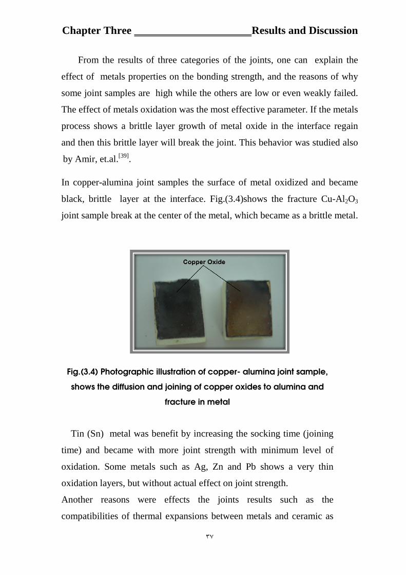
In copper-alumina joint samples the surface of metal oxidized and became
black, brittle layer at the interface. Fig.(3.4)shows the fracture Cu-Al2O3
joint sample break at the center of the metal, which became as a brittle metal.
Fig.(3.4) Photographic illustration of copper- alumina joint sample,
shows the diffusion and joining of copper oxides to alumina and
fracture in metal
Tin (Sn) metal was benefit by increasing the socking time (joining
time) and became with more joint strength with minimum level of
oxidation. Some metals such as Ag, Zn and Pb shows a very thin
oxidation layers, but without actual effect on joint strength.
Another reasons were effects the joints results such as the
compatibilities of thermal expansions between metals and ceramic as

ts and DiscussionResul Chapter Three
٣٨
we have already discussed in chapter one, and its effects on the joint
strength. Fig.(3.5) represents the relationships between bonding
strength with the compatibility of thermal expansion of the joint
partners.
Fig.(3.5) Histogram between bonding strength with the compatibility of
thermal expansion of the joint partners.
The relationship of bonding strength with atomic number were much
more complicated and needs more research to understand it. Fig.(3.6)
represent this relation. Ignoring the effect of oxidation on the joint
strength for Al and Cu metals, bonding strength seems to be reduce
with atomic number, which means the difficulty of solid state diffusion
process with higher atomic numbers.

ts and DiscussionResul Chapter Three
٣٩
Fig.(3.6) Relationships of bonding strength with atomic number
Fig.(3.7) represent the relationships between bonding
strength and mass number. Ignoring the effect of oxidation on
the joint strength for Al and Cu metals, bonding strength seems to be
reduce with mass number also, which means the difficulty to realize
the solid state diffusion process with higher mass numbers.
Fig.(3.7) Relationships of bonding strength with mass number

ts and DiscussionResul Chapter Three
٤٠
When the joint samples were tested by tensile machine the result show three
types of fracture.
1.Fracture in the interface , this type is clear in the Zn , Pb samples.
Fig.3.8(a, b) illustrate this type of fracture.
(a) Pb Sample
(b) Zn Sample
Fig. (3.8) Fracture in the joint interface for Pb and Zn samples

ts and DiscussionResul Chapter Three
٤١
2. The fracture in the alumina part , this type of fracture is clear in Ag- Al2O3
joint as shown in figure (3.9).
Fig. (3.9) The fracture in alumina part for Ag sample
3.The fracture in metal part , this type is clear in Cu sample when all atoms
of copper are oxidized and became brittle and some of them diffused in
alumina parts and covered two alumina surfaces, as shown in the previous
figure (fig. 3.4).
3.3 Elemental Analysis
X-ray fluorescence technique was used for testing each face of the
samples, which will prove a meaningful tool to study the diffusivity between
the joint surfaces of dissimilar materials in solid state. The elemental analysis
of the weak joined faces for each sample as it is illustrated in fig.(3.10), were
conducted and revealed in fig,s (3.11) to (3.16).

ts and DiscussionResul Chapter Three
٤٢
Fig. (3.10) Fracture sample faces
The X-Ray fluorescence technique was used (for each sample) to achieve
the three type of fracture categories. The X-ray fluorescence for face1 for all
samples are shown in figs.(3.11-3.16).
Fig. (3.11) X-ray fluorescence of Silver- Alumina sample (face-1)
ts and DiscussionResul Chapter Three
٤٣
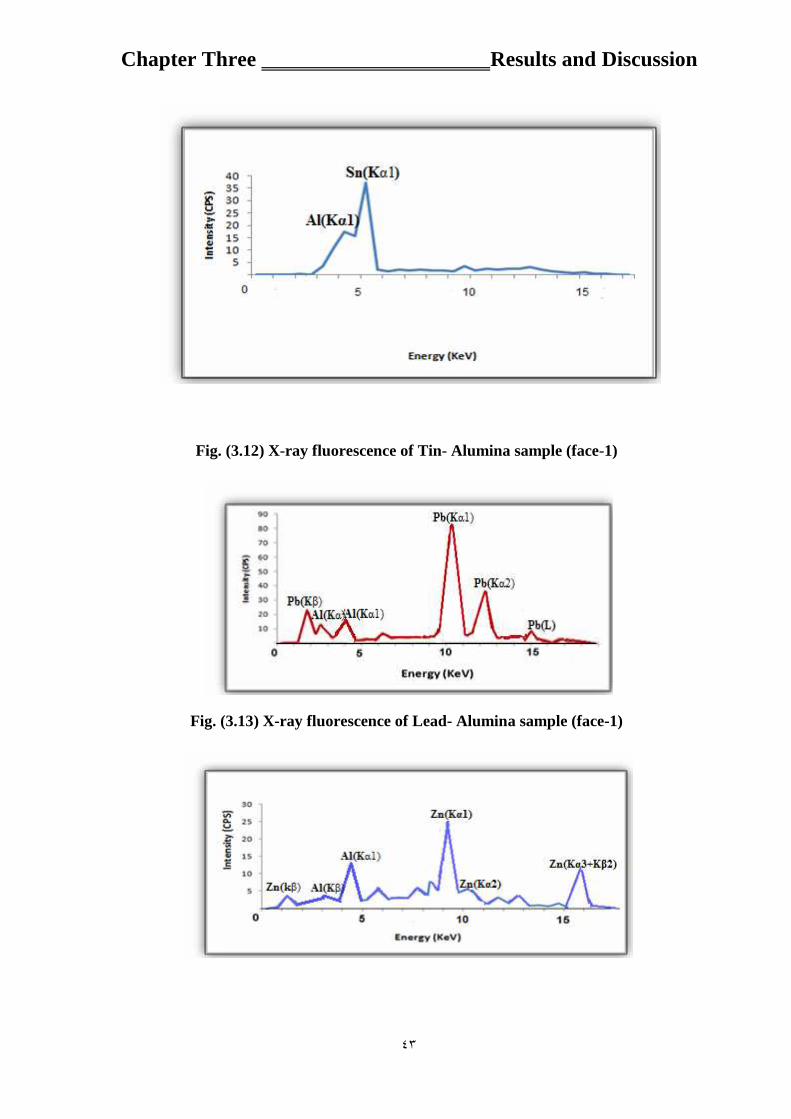
Fig. (3.12) X-ray fluorescence of Tin- Alumina sample (face-1)
Fig. (3.13) X-ray fluorescence of Lead- Alumina sample (face-1)

ts and DiscussionResul Chapter Three
٤٤
Fig. (3.14) X-ray fluorescence of Zinc- Alumina sample (face-1)
Fig. (3.15)X-ray fluorescence of Copper-Alumina sample (face-1)
Fig. (3.16) X-ray fluorescence of Aluminum- Alumina sample (face-1)
The X-ray fluorescence for all samples of face2 as shown in figs(3.17-3.22)

ts and DiscussionResul Chapter Three
٤٥
Fig. (3.17) X-ray fluorescence of Silver-Alumina sample (face-2)
Fig. (3.18) X-ray fluorescence of Tin-Alumina sample (face-2)
Fig. (3.19) X-ray fluorescence of Lead-alumina sample (face-2)

ts and DiscussionResul Chapter Three
٤٦
Fig. (3.20) X-ray fluorescence of Zinc-Alumina sample (face-2)
Fig. (3.21) X-ray fluorescence of Copper-Alumina sample (face2)
Fig. (3.22) X-ray fluorescence of Aluminum-Alumina sample (face-2)
3.4 Optical Microscopic
The identification of two fracture surfaces were carried out by optical
microscope. Optical microscope gives clear evident pictures for all samples
and express the causes of the weakness of the bonding, such as the effect of
oxidation. The characterization of the two fracture surfaces (face 1and face2)
were illustrated in figs.(3.22) up to (3.34).

ts and DiscussionResul Chapter Three
٤٧
Fig.(3.23) Optical Microscope image for face1 for silver sample.
(Magnification 500x)
Fig.(3.24) optical microscope image for face2 for lead sample.
( Magnification100x)

ts and DiscussionResul Chapter Three
٤٨
Fig.(3.25) Optical Microscope image for face2 for copper sample.
(Magnification 50x)
Figure(3.25) shows the red point regions , this regions mean the
copper metal is oxide, also clear in fig.(3.24) of lead sample.
The diffusivity was successes in all samples and this evident in
figs.(3.20-25).
Fig.(3.26) optical microscope image for face1 for Aluminum.
( Magnification 200x).
Fig.(3.27) optical microscope image for face1 for lead.
( Magnification100x).

ts and DiscussionResul Chapter Three
٤٩
Fig.(3.28) optical Microscope image for face1 for Zinc.
( Magnification 100x)
Fig.(3.29) optical Microscope image for face1 for Copper.
(Magnification 100x )
Fig.(3.30) optical Microscope image for face1 for Silver.
( Magnification 100x)

ts and DiscussionResul Chapter Three
٥٠
Fig.(3.31) optical Microscope image for face1 for Tin.
(Magnification 200x).
Fig.(3.32) shows the diffusivity of alumina in copper in tangential
section.
Fig.(3.32) optical microscope image for Copper-alumina in tangential
section.(Magnification 100x)
Fig.(3.33) shows the inflated region in tin -alumina sample, so
some region is higher than others.

ts and DiscussionResul Chapter Three
٥١
Fig.(3.33) optical microscope image for Inflated region for Tin.
( Magnification 200x)
Fig.(3.34)and (3.35) showed the crack is clear in alumina part of
zinc-alumina sample.
Fig.(3.34) optical Microscope image for face2 for Zinc.
( Magnification 100x).

ts and DiscussionResul Chapter Three
٥٢
Fig.(3.35) optical Microscope image for face2 for Zinc.
(Magnification 50x)
3.5 Phase Identification
In order to detect the chemical nature of interlocking , an
XRD pattern recorded for alumina which had been previously
bonded with Sn for two faces (face1, face2) and alumina pure
as shown in fig.(3.36)[48,49]. These patterns shows that no
chemical reaction had occurred. The nature of the bonds
between the metals and alumina ceramic is not yet clear
whether it is of chemical or physical nature. The basic principle
underlying the mechanism of bond formation between an ionic
and metallic system is not yet fully understood[38].

ts and DiscussionResul Chapter Three
٥٣
(a)
(b)
(c)
Fig.(3.36) X-ray diffraction. (a) X-ray diffraction of Al2O3 pure sample. (b)
X-ray diffraction of Sn sample face1. (c) X-ray diffraction of Sn sample
face2.

The conclusions and Future Work Chapter Four
٥٣
The Conclusions and Future Work
4.1 The Conclusions
Conclusion of the present work can be summarized by the following
remarks:
1. Selected metals would diffuse to alumina ceramic if the components
are maintained in close contact under predetermined pressure and heated
to about 90% of their melting points. The pressure that necessitate good
bonding was 0.3MPa (N/m2) for all metals.
2.The bond strength in silver and tin metals is greater than zinc and lead
metals. However, no bond were detected in copper and aluminum
because of oxidation effect for long bonding time(2h).
3.The X-Ray diffraction of all samples were showed no chemical
reaction between ceramic and the metals.

The conclusions and Future Work Chapter Four
٥٤
4.2 Future Work
1.Other parameters affected on diffusivity, such as pressure and different
atmospheres should be investigated.
2.Other metals foils with different thicknesses can be joined with ceramic
to attempt the bond strength.
3. Fractured surfaces can be characterized by using advanced techniques
such as electron spectroscopy for chemical analysis (ESCA) to obtain
more surface information(elements, phases, depth of diffusion).
4.Interfacial reactions and rate of diffusivity should be studied
theoretically, for different joining atmospheres.

٥٥
References
1. Donald, R. Askeland, Pradexpp P. " The science and engineering of
materials" , Thomson, 2009.
2.Iver Brevik, V. N. Marachevsky, Kimball A. Milton, " Identity of the
Van der Waals Force and the Casimir Effect and the Irrelevance of
these Phenomena to Sonoluminescence" Invited Lectures at 17th
Symposium on Theoretical Physics, Seoul National University, Korea,
June 29-July 1, 1998.
3. Thamer A. J. , "effect of Titanium in filler alloy on the joining
strength of alumina bonded kovar" M.Sc. Thesis, Bagdad University,
College of Science, 2000.
4.Walter D. Pilkey, Orrin H. Pilkey , "Mechanics of solids" , Metals and
Ceramics Information Center, Columbus, p. 292, (1974).
5.M. G. Nicholas and RJ Lee, "Joining of dissimilar materials'' , the
journal of the institute , V.5 , No.6 , 1989.
6. Rahn, Armin, " The Basics of Soldering" John Wiley & Sons,
(1993).
7. Wang, Juan, Liyajiang and Mahaijun " Effect of Cr and Ni on
diffusion bonding of Fe3Al with steel" Indian Academy of Sciences,
Bull. Mater. Sci., Vol. 28, No. 1, February 2005.
8. Derby B. and Wallach E.R. “Theoretical model for diffusion
bonding” ,Metal Science, Vol. 16, 49-56., (1982).
9.Cline C.L., “An analytical and experimental study of diffusion
bonding” , Welding Journal Research Supplement, November, 481s-
489s.. (1966).

٥٦
10.William D. Callistr ,"Fundamentals of materials and science and
engineering" , John Wiley and Sons, 2007.
11. Amir. Sh., ''Introduction to mechanical properties of materials"
University of Cambridge , Surface and Interface Analysis, 2009.
12. Melvin M. ,"Introduction to Mechanical Properties of materials"
Eisenstadt collier Macmillan publishers, Ch. 10, London, 1971 .
13.Lawrence H.Vane Vlack, "Elements of materials science and
engineering", sixth addition , Wesley publishing company,1989.
14.Johr Wiley and Sons, "Introduction to Solid State Physics" ,New
York Manchester, 1986.
15. Ghazi.K.S. , "Ceramic cutting Tools Preparation and Testing"
Ph.D. Thesis , Bagdad University , College of Science ,1998.
16. Walter H. k. , "Material and techniques for electron tubes"
Reinhold publishing Corporation ,1960.
17. G .Ptzow, T. Suga , G. Elssner and M-Turwitt, "Nature and
Structure of Metal-ceramic interface "proceeding of third Int. School of
centering materials , New Delhi, 1983.
18.H.Mizuhara and E. Huebel and T. Oyama , "High Reliability Joining
of Ceramic to Metal " vol.86,No.9 Ceramic Bulliten ,1986.
19. Z. A. Sarkiss , "Fracture and Surface Analysis of Powdered Glass-
Metal Joined Interface" Ph . D Thesis , Bagdad university , College of
science, 1997.
20. T. Mulvey and R.K. Webster , "Modern Physics Techniques in
Material Technology " , Oxford University press 1974.

٥٧
21. J.M. Blakely , "Surface Physics of Materials" , Published by
Academic Press, Vol. II , London , 1975.
22. Ron Jenkins ,"X-ray Fluorescence spectrometry " published by John
Willey and Sons , 1988.
23. D.R. Sabir , "X-Ray Fluorescence analyses Fe-Co-Ni Ternary
System by Empirical Coefficient Method " M.Sc. Thesis , Bagdad
university , College of education , 2000.
24. Roth A. "Vacuum sealing techniques" , First edition , Pergamon
press , 1966.
25. Barta I.M. “Low temperature diffusion bonding of aluminum
alloys” Welding journal Research Supplement, June, 241s-247s, June ,
1964.
26. Bienvenu Y. and Koutny J.L., “Diffusion Bonding of Thin
Aluminum Foils” Proc. Conf. Diffusion Bonding 2, Cranfield Institute of
Technology, Cranfield, UK, 111-118, ed. Stephenson D.J, Amsterdam,
Elsevier, 1990.
27. Church S., Day J. and Wild B. “Diffusion Bonding of Metals and
Alloys” Materials World, Vol. 4, No. 7, 385-386, 1996.
28. John J.B. Alvin E.G., Arum . T. "Advances in joining Technology "
Metals and ceramics Information Center , Columbus, Ohio ,1975.
29. Amir A. Sh., "Diffusion Bonding Aluminum Alloys and
Composites: New Approaches and Modeling" University of Cambridge
December 1997.
30. Crank J. "The mathematics of diffusion" Clarendon Press, Oxford
1975.

٥٨
31. M.G. Nicholas and R. J. Lee "joining dissimilar materials" V.5 ,
No. 6 ,1989.
32. Yuichi Y. , "role of oxygen in bonding copper to Alumina " J.Am.
Ceramic Soc. 1989.
33. Mamora Nakamura and ststhis D. Peteves "Solid State Bonding of
Silicon Nitride Ceramic with Nickel Chromium Allot Interlayers"
Vo.73, No.5, 1990.
34. Irfan A.Y, Sare C.and Ibrahim C. "Comparison of Properties of
Friction and Diffusion Welded Joints Made Between the Pure
Aluminum and Copper Bars" BAÜ Fen Bilimleri Enstitüsü Dergisi
(1999).
35. C-D. Qina and B. Derby "Diffusion bonding of nickel and zirconia:
Mechanical properties and interfacial microstructure" Department of
Materials, University of Oxford, Parks Road, Oxford OX 1 3PH, United
Kingdom, 1992.
36. Bernard Y. , "Thermal Expansions " Plenum Press, New York ,
1972.
37. Jasenka Z., Josip P., Janez I., Tomislav I. "Bond Strength of Gold
Alloy-Hydrothermal Ceramic Interface" , Acta Stomatol Croat, Vol.35,
Br.2, 2001.
38. Zareh. A.S., N.N Rammo, Razac. H. Y. and Thamer. A. J. , " Solid
State Diffusion Bonding of Metals to Ceramic " Science J. ,Iraq, 2001.
39. Amir. A. Sh., H. Assadi and E.R. Wallach " Interface Evolution and
Bond Strength when Diffusion Bonding Materials with Stable Oxide
Films" Surface and Interface Analysis 2001; 31:609-618.

٥٩
40. Kenneth D., Melissa J. A., Jennifer A. D., Young B. P., Matthew J.
C., and Harry A. A. , "Silver diffusion bonding and layer transfer of
lithium niobate to silicon" APPLIED PHYSICS LETTERS 93, 092906 ,
2008.
41. Jonathan A.S and J. L. Shannon , "Crack growth Resistance of
textured alumina " J.Am. Ceramic Soc.72[1] , PP.20-27, 1989
42. Bidermann , George , Sillen L. G. , "Studies on the Hydrolysis of
Metal Ions Part 30 , a critical survey of the solubility equilibrium of
Ag2O " Acta chemical scandinavica 14:717, 1960.
Laurel M. S. , "Evolution of NDE continues for ceramics " Vol.70,
No.8 ceramic Bulliten , 1991.
43. D. Douglas Berger , "Joining Tantalum to Alumina by Brazing "
Welding Journal , 1981
44. Astm, "Standard Test Method for water absorption, bulk density ,
apparent porosity and apparent specific gravity of fired white ware
products" C373-88 , 1988
45. Erik. C.M. and Wolfgang G. ,"Precise Non Destructive
Determination of Density of Porous Ceramics " J.Am. Ceramic Soc.
72[7],pp .1268-70,1989.
46. M. G. Nicholas , "Active Metal Brazing " British Ceramic Trans. J,
85 , PP.144-146, 1986.

٦٠
47. W.E. BORBIDGE, R. V. ALLEN and P. T. WHELAN, "Technique
for Joining Ceramic to Metals" space cl-13 p.o box 160 , 1986
48. L. A. Rocha, E. Arizaa, A. M. Costaa, F. J. Oliveirac and R. F. Silvac
, "Electrochemical Behavior of Ti/Al2O3 Interfaces Produced by
Diffusion Bonding" Vol. 6, No. 4, 2003.

ا�����دن &% ا�� ا$#� ح�� �ا�ب! ا ����ري ب�� ا���ا��� وا������ درا� إ� ا��� ���ف
وا�ص�صا)�رص�� وا5�/�4م و وا/��س ا12 و ( ا/.�وةم ا���دن +�� ت( ا��)�ا
�Dض �٢(1x1و���ح ت.��� �#( ١+#� ش?< ر=�ئ; ب��� وت��:��� �وت( ت.���9 )ا.$��� .ا5��4/�� �رب��9 ب���ا�
+#��� +�#��ت واج��J �٣( .1x1x50 ا ��4/� +�� ا/.�وة وبHب��د ت( ت����G� ��1تL�M/ص.< وت . وت��:��� #�ب! ب����دن ا�)�2#
( ت/L�M ا/��ذج ب�9ق ت/L�M ���و& و&; �4اص�2ت +��� �����ة و�� P( وضN ش��� ت
ت����ا 4ض��� داخ< ا�2ن ا��� ��?� ب��?�ل 0.3 � وض��9D ب.4ةا���ن ب�� =��9% ا ��4/ ب�رج ح�ارة +4�G�ا �ا�$��ر ا���ن و��ة �� درج ٩٠%�Vا ا�Dض ��) ت��(
���+��.
ا�ب! ا ����ري 12# وا.$��� �N إن ت��� أ#���% +�#� آ�� ا�2$< إج�اءب�� ����
ا�ب! إن ت��� أخ�ى و�� ج� ، ب��?�ل +#� ا�4ا86,5x 10⁴% �����ا ��4/� +�% ���� . �N ا ��4/� آ��J ض��2 ج�اًوا5�/�4م?< �� ا/��س
����G� ��?ئ` ا��� J41ئ%در�ا ��G�( ب���)�ام ا OM(و ا5ش� آV� ب���)�ام ت./�
و�� خcل هaV )(XRD)ح�4د ا5ش� ا��/� و(XRF) رة ا5ش� ا��/� (ا��/� ب/4+��� ب ا�ئ������ ا اح�ىإنا�را� وج� ا�Hآ�� ا��Pe +#� ا ����ر� و=4ة ا�ب! ه4 +�#�
.اج�اء +�#��ت ا�ب! إP/�ءا�% ت��ث #���ن
ا ����ر� ب�� ا���ن وج4دJاXRF(��P وXRD( ا��/� وا5ش� )OM( ا���G&�4ص
g�& ا��� وان���وا �4اد اJ�P +�م وج4د ت�2+< آ����ئ% ب��(XRD) ا��/� ح�4د ا ش� .ا�ب! ا���)�� &% هVا ا���
���9 ا?�� ت��� وج4د cPث ه�:�ت #?�� وه% :ا/��ئ` ا��#�
ا?�� &% ا���ا��� .١
ا?�� &% �/9. ا�2ص# ب�� ا���ن وا���ا��� .٢
ا?�� &% ا���ن.٣

ر�� ا���اق ��
وزارة ا������ ا����� وا���� ا����� آ��� ا���م / �م�� ا������
$#� ا�"�!��ء
دن .� ا����� �دراس� م��ن� ا��ب+ ا*ن�)�ري ب�� ا�#��ام�% وا��� ا����0
رس��� م34م� أ�1 �م�� ا������ /آ��� ا���م/$#� ا�"�!��ء
� م����8ت ن�6 در � م� #��� .� ا�"�!��ءآ5!ء م
م� 6�$� ا��8;�أروى �9زي ن�
ب<��ر�س >�م .�!��ء
بAش�اف
>�3 ا���5ر ����Eم� .زار�D ازات س�آ�C د .د
١٤٣١- ر�ن ٢٠١٠-�ب