Embed Size (px)
Citation preview

HAL Id: hal-01366888https://hal.archives-ouvertes.fr/hal-01366888
Submitted on 5 Feb 2020
HAL is a multi-disciplinary open accessarchive for the deposit and dissemination of sci-entific research documents, whether they are pub-lished or not. The documents may come fromteaching and research institutions in France orabroad, or from public or private research centers.
L’archive ouverte pluridisciplinaire HAL, estdestinée au dépôt et à la diffusion de documentsscientifiques de niveau recherche, publiés ou non,émanant des établissements d’enseignement et derecherche français ou étrangers, des laboratoirespublics ou privés.
Investigation on the influence of jetting equipment onthe characteristics of centrifugal pumpQiaorui Si, Shouqi Yuan, Jianping Yuan, Gérard Bois
To cite this version:Qiaorui Si, Shouqi Yuan, Jianping Yuan, Gérard Bois. Investigation on the influence of jetting equip-ment on the characteristics of centrifugal pump. Advances in Mechanical Engineering, Sage Journals,2016, 8 (8), pp.168781401666028. �10.1177/1687814016660287�. �hal-01366888�

Investigation on the influence of jettingequipment on the characteristics ofcentrifugal pump
Qiaorui Si1, Shouqi Yuan1, Jianping Yuan1 and Gerard Bois2
AbstractTo reduce radial noises from the motor of centrifugal pumps, this study designed a water cooling system called jettingequipment to replace traditional fan cooling systems in pump motors. By measuring radiated noises, head, efficiency, andcavitation performance, the research compared the differences among experimental results of the original pump unit,the one with a normal design jetting pipe and another one with a larger jetting pipe. Results show that the radiatedsound pressure level of the model pump was significantly reduced by 8.3 dB after integrating the jetting pipe. With a nor-mal jetting pipe, no significant changes were observed in the head, efficiency, and shaft power curves, and cavitation per-formance improved under small flow rate. However, the performance with the larger jetting pipe worsened, except thehump phenomenon of the model pump under a small flow rate was enhanced. Computational fluid dynamics methodwas used to calculate the internal flow of three model pumps in order to investigate the jetting flow effect. A compari-son among the flow fields at the inlet of the three types of pumps indicated that high-pressure water injection can effec-tively control inlet recirculation and improve velocity distribution in the inlet flow field with decreased recirculationvortex strength and recirculation onset critical flow rate.
KeywordsCentrifugal pump, jetting equipment, noise reduction, pump performance, computational fluid dynamics
Date received: 16 December 2015; accepted: 28 June 2016
Academic Editor: Yuning Zhang
Introduction
As one of the most important fluid transportation andenergy conversion devices, the centrifugal pump hasbeen widely used in various applications and fields,including ships, submarines, and aeronautics.1,2 Withthe trend of increasing speed and efficiency as well ashigher environmental standards and greater clientrequirements, radiated noise control of centrifugalpumps has become an important problem that requiresa prompt solution. Traditional motor centrifugalpumps consist of a motor and a pump. The noisemainly includes hydraulic noise caused by inner flow,mechanical noise, and motor noise.3 Heat dissipationof the pump system always operates with the assistance
of a fan, which is usually set at the end of the motorwith high rotating speed. Hence, a fan cooling systemis the main reason for radiated noise of motor centrifu-gal pump systems.
This problem was previously addressed by designinga water cooling system to reduce radiated noises.However, this approach increases designing and
1National Research Center of Pumps, Jiangsu University, Zhenjiang, China2LML, UMR CNRS 8107, Arts et Metiers ParisTech, Lille, France
Corresponding author:
Shouqi Yuan, National Research Center of Pumps, Jiangsu University,
Zhenjiang 212013, China.
Email: [email protected]
Creative Commons CC-BY: This article is distributed under the terms of the Creative Commons Attribution 3.0 License
(http://www.creativecommons.org/licenses/by/3.0/) which permits any use, reproduction and distribution of the work without
further permission provided the original work is attributed as specified on the SAGE and Open Access pages (https://us.sagepub.com/en-us/nam/
open-access-at-sage).

operating costs. The pump itself is used for liquid trans-portation, which is why some researchers attempted toemploy jetting equipment. In this approach, the liquidgoes from the outlet of the pump and back to the inletafter cooling the system of the motor. With partialhigh-energy flow guided back to the inlet, the inner flowof the pump is likely to be influenced, especially at theinlet. Centrifugal pumps under a small flow rate mayexhibit reverse flow and cavitation. Studies have shownthat this condition may cause hydraulic vibration andnoises as well as result in pipe blockage.4–7 Cui et al.8
state that reasonable jetting equipment may improvecavitation performance of high-speed centrifugal pumpsbased on experimental and theoretical analysis. Yanget al.9 and Zhang et al.10 focus on the influence of high-pressure fluid to control the backflow phenomenon.However, the above-mentioned research focuses onlyon the effect of high-pressure fluid on the inlet alone.Few comprehensive studies focus on synthesized jettingequipment.
This article changed the fan cooling system of a tra-ditional centrifugal pump into water cooling one withjetting equipment. By measuring radiated noises, head,efficiency, and cavitation performance, the researchcompared the differences among experimental resultsof the original pump, the one with a normal jetting pipeand another one with a larger jetting pipe.Subsequently, the entire flow field of the pump model,including the pump chamber and jetting flow, wasestablished to process the numerical simulation.Internal flow fields of the three pump models were cal-culated based on Reynolds-averaged Navier–Stokesmodel to analyze the backflow phenomenon and thecontrolling effect on this phenomenon.
Design of jetting equipment and testintroduction
The selected model is a commercial single-stage, single-suction, horizontally oriented centrifugal pump, whichhas specific speed of 88.6. The specific speed of thepump is defined as shown in formula 1. The pump cas-ing is typically combined with a spiral volute. Thedesign parameters of the pump are shown in Table 1.In this type of pumps, the motor shaft directly drivesthe impeller, which allows to design a jetting equipmentinstead of the fan cooling system. The model pump andthe design of the jetting equipment are shown inFigure 1
ns =3:65n
ffiffiffiffi
Qp
H3=4ð1Þ
Motor characteristics and electromagnetic calcula-tion indicate that the total cost of the motor, named PL,is equal to 1.5 kW. During stable operation of the
motor, the costs will be transformed into thermalenergy, which is then utilized by recycling water. Hence,the required radiating power is also 1.5 kW. Accordingto the formula on thermal energy absorbed from thewater jacket by the cooling water
F9=a p dylDT ð2Þ
where a is the convective heat transfer coefficient,which is equal to 1200W/m2K; DT refers to the differ-ence in temperature between water-jacket wall andwater, which is equal to 15�C;11 and l is the length ofhelical water groove, where the water jacket determinedby the motor’s construction is around 2.5m long. As aresult of bidirectional convection, the equivalent lengthis 5m. The thermal energy F# absorbed by watershould be larger than the radiated heat from the motor.Hence, after calculation, the diameter of the water-jacket pipe should be larger than 5.3mm. Therefore,6mm is selected in this study for processing conveni-ence. Detailed structural design of this water-cooledelectric centrifugal pump could be seen in patent
Table 1. Pump parameters.
Parameters Value
Design flow rate Qn 50 m3/hDesign head Hn 34 mRotation speed n 2900 r/minMotor rated power P 7.5 kWBlade number Z 6Suction diameter Ds 75 mmExhaust diameter Dd 50 mmOuter diameter of the impeller D2 174 mmBlade width at the impeller outlet b2 12 mmBase diameter of the volute D3 184 mm
Figure 1. Schematic diagram of model pump and the design ofjetting device: (1) impeller, (2) pump casing, (3) sieve, (4) screw,(5) steady pressure jar, (6) valve, (7) cavity, (8) motor casing, (9)cavity, (10) pipe, and (11) jetting pipe.

documents.12 Since the diameter of jetting pipe plays amajor role, a larger diameter, namely, 12mm, is alsodesigned to process the investigation on the influenceof jetting equipment on the characteristics of centrifu-gal pump.
Experiments were conducted in a closed-loop sys-tem, the installation diagram of which is shown inFigure 2. The inlet gate valve was kept open during themeasurement, and the outlet gate valve was used to reg-ulate the flow. A turbine flow meter was used to mea-sure flow Q. Turbine flow meter precision is 6 0.3%,and output standard electrical signal ranges from 4 to20mA. Speed n is measured using a tachometer.During the experiment, two dynamic pressure transmit-ters which have a 6 0.2% precision and are capable ofproducing standard electrical signals were used to mea-sure the inlet pressure (Ps) and the outlet pressure (Pd).Measurement range at the inlet is 2100 to 100 kPa andthat at the outlet is 0 to 1MPa. A vacuum was used toprocess the cavitation performance measurement.Based on each measurement device, comprehensiveerror of this test rig on testing pump performance couldsatisfy the second level of national standards of ChinaGB/T3216-2005 and also International Organizationfor Standardization (ISO) 9906:1999.
In the test rig shown in Figure 2, the followingexperiments were processed on the original pump,6mm jetting pipe, and 12mm jetting pipe equipment:(1) experiment on radiated noises, (2) model pump per-formance at fixed rotary velocity, and (3) cavitationexperiments at different flow rates and fixed rotaryvelocity. The sound pressure level of pump-radiatednoises was collected using a digital sound level meter,whose resolution is 6 0.1 dB. During the experiment,the inlet valve was fully open, and the outlet was closedbefore turning on the centrifugal pump. We adjustedthe frequency converter to keep n, the pump rotary
velocity, fixed at 2900 r/min, while exporting air in thevoltage regulator tank. Through control of the outletvalve, 25 flow rate points from 0 to 1.4 Qn were used todefine pump performance. Signals of static pressure atthe inlet and the outlet, rotary velocity, flow rate, andmotor parameters were collected during stable opera-tion. With regard to cavitation measurement, theexperiment was processed under three flow rates,namely, 0.7Qn, Qn, and 1.2Qn, with fixed rotary velo-city and adopted reducing available net positive suctionhead (NPSHa) method to obtain cavitation perfor-mance curves. After each vacuum pumping, we col-lected the outlet static pressure, rotary velocity, andelectric parameters when the system was stable. At eachmass flow rate, 20 groups of data are collected.
Test results
Measurement results of radiated noise from threepumps
The radiated noise experiments of three pump modelswere carried out based on ISO 4412-1:1991.13 The test-ing point is located horizontally 1m to the surface ofthe pump body as shown in Figure 3(a). Sound pres-sure level of the pump was calculated by the average ofall measuring points. Figure 3(b) shows the sound pres-sure level variation in accordance with the flow rate forthe three pump models. The sound pressure level of thethree pumps that the original pump, the pump with a 6mm jetting pipe and the pump with a 12 mm jettingpipe initially increased with the flow rate and thendecreased with the flow rate to the lowest point at thedesigned flow rate and increased soon. This conclusionis in accordance with the flow-induced noise measure-ment of the inner pump flow field.7 Greater mass flowrate may cause cavitation, which would cause headreduction and increased radiated noises. Moreover, theaverage sound pressure of the system noise was reducedby approximately 8 dB before the motor fan wasremoved, and the difference between 6- and 12-mm-diameter jetting pipe was not evident, with an averageof 0.3 dB because of large background noise. Figure3(c) displays the sound pressure level variation alongwith the decrease in inlet pressure. The noise levels ofthe original pump and those of the pump with a 6-mm-diameter jetting pipe increased suddenly when the pres-sure was less than 260kPa. A similar law applies tothe pump with a 12-mm-diameter jetting pipe when theinlet pressure was less than 250kPa, which may indi-cate that cavitation occurred. The average sound pres-sure of system noise following the decrease in inletpressure reduced to 79.2 and 79.9 dB from 86.87 dBbefore the motor fan was removed. Overall, theradiated noises of the pump system with 6mm diameterjetting pipe showed the best results.
Figure 2. Test rig of the centrifugal pump measurement: (1)cavitation tank, (2) inlet butterfly valve, (3) model pump, (4)piezometer tubes, (5) voltage regulator tank, (6) turbine flowmeter, (7) outlet butterfly valve, and (8) vacuum pump.

Measurement results of performance curves fromthree pumps
Figure 4 shows the head, efficiency, and shaft powercurves in accordance with flow rate. Compared with theoriginal pump, the pump with a 6mm jetting pipe haslittle differences in head, efficiency, and shaft power. Bycontrast, the pump with a 12mm jetting pipe has appar-ent differences in head, efficiency, and shaft power.Under a small mass flow rate, the pump with a 12mmjetting pipe more obviously favored the hump of thehead curve. This pump consumes more energy than theother two because the jetting pipe enlarged the impellerflow. With the mass flow rate of the pump increases,efficiency and head dropped quickly because the jettingpipe flow enlarged the real flow rate at the impellerresulted in cubage loss.
Measurement results of cavitation performancecurves from three pumps
High-energy fluid guided by jetting equipment from theoutlet to the inlet of the pump results in a
transformation into pressure energy at the inlet. Hence,the fluid may enhance cavitation performance theoreti-cally. Figure 5 shows the cavitation curves of the threemodel pumps under 0.7 Qn, Qn, and 1.2 Qn. NPSHr,which is the critical cavitation margin, is set based onthe margin when the head drops by 3%. Results showthat NPSHr always increases along with mass flow ratefor all three model pumps, which shows the same con-clusion in other literatures.14 Under 1.2 Qn, relativelystrong unstable cavitation was observed on the curve asa hump appeared in the original pump, whereas the jet-ting flow could improve this condition. Compared withthe original pump, NPSHr decreased slightly under0.7Qn for the pump equipped with 6-mm-diameter jet-ting pipe, but increased under Qn and 1.2 Qn. It makessense that the recirculation of high-stagnation pressurefluid caused by the jetting pipe flow could enhance cavi-tation performance because it brings higher saturationpressure margin under 0.7 Qn. In the pump equippedwith 12-mm-diameter jetting pipe, NPSHr increasedunder all three mass flow rates. This condition occursbecause higher leakage caused by the jetting pipe wor-sens cavitation performance and vertical jetting flow
Figure 3. Sound pressure level of radiated noises from three pumps: (a) SPL measurement points,13 (b) SPL variation withincreased mass flow rate, and (c) SPL variation with decreased inlet pressure at Q = Qn.

into the inlet pipe, thereby disturbing the flow pattern,both of which balance out the improvement.
Numerical simulation of the influence ofjetting equipment on pump inlet flow field
The measurements showed that the jetting equipmentsignificantly influences the inlet flow field of the pump,which results in variation in the performance and cavi-tation curves.15 Backflow phenomena is alwaysobserved at the inlet when the pump operates at smallmass flow rates, which may disturb the surroundingflow field and cause vibration and noise problems.16
Import pressure at the inlet is an effective way to con-trol the backflow. Therefore, this section carried outnumerical solutions on the entire flow field of the threepump models as well as analyzed the effect of jettingflow on pump inlet flow field using computational fluiddynamics (CFD) method.
Three-dimensional calculation model and simulationmethod
The clearance flow between the pump chamber and theimpeller inlet has a great effect on the inlet flow field of
the pump, which has been considered to be the mainreason for the calculation deviation.17 Therefore, webuilt the hydraulic model in strict accordance with thesize of centrifugal pump flow components. To minimizethe interface number, the model is divided into fiveparts: inlet pipe, outlet pipe, jetting pipe, impeller(rotating domain), and pump casing (stationarydomain), which includes the volute and the side cham-bers between the impeller and the volute to take leak-age flow effects into account, as shown in Figure 6.Inlet and outlet pipe domains were carried out toextend the treatment to ensure that the flow, includingthe jetting flow, closed in a fully developed condition atthe inlet and outlet, thereby providing better results forthe flow structure.
Structured grids of the domains were generated withICEM-CFD 12.1, and care was taken to concentrate onthe grid in the wear rings and tongue region of thevolute, as shown in Figure 7(a). The total number ofgrid nodes is 5,445,910, and the number of grid ele-ments is 5,207,832 for rotating and stationary domainsof the original pump. Similar independence of the solu-tions from the number of grid nodes has been provenby simulating the flow field with different numbers ofgrid nodes according to previous work.18,19 The only
Figure 4. Comparison of pump performance: (a) head, (b) efficiency, and (c) shaft power.

difference in the pumps with jetting equipment is theaddition of the jetting pipe domain in the calculation,with a total number of grid nodes of 5,495,910 and with
diameters of 6mm and 5,565,910 with diameters of12mm. The near-wall mesh was applied to ensure non-dimensional normal distance from the blade surface,that is, y+, located in the suitable region because ofthe adopted automatic near-wall treatment. As shownin Figure 7(b), the distributions of y+ are below 20, asobtained in the pump casing and also the blade surface.
Based on the finite volume method, the three-dimensional (3D) steady turbulent flow in pumps wassimulated under different conditions using the shearstress transport (SST) turbulence model. The total pres-sure was specified at the inlet of the suction pipe,whereas the outlet condition is mass flow rate, both ofwhich were obtained from laboratory tests. The inter-nal and external impeller surfaces were modeled using arotating wall, in which the speed equals the nominalrotating speed, whereas all other walls were stationary.A smooth wall condition is used for the near-wall func-tion. Furthermore, the interfaces between the rotor andtheir neighboring sub-domains were set up as frozenrotors, which is a common procedure for steady-statecalculation. In addition, iteration stops when the rootmean square residual dropped below 1025.
Figure 5. Cavitation performance curves: (a) Q = 0.7 Qn, (b) Q = Qn, and (c) Q = 1.2Qn.
Figure 6. Three-dimensional model of calculation domain: (1)inlet pipe, (2) impeller, (3) pump casing, (4) outlet pipe, and (5)jetting pipe.

Discussion of numerical simulation results
Analysis of the inlet flow field from original pumpcalculation. Figures 8 and 9 show numerical simulationresults of the original pump with overall flow field cal-culation. In comparison with experiment results, thenumerical ones always appear to be higher than theexperiments as shown in Figure 8(a). This difference iswithin 5%, which means numerical results could beused for further research. The research sets severalmonitoring points (shown in Figure 8(b)) along theradius on the circular impeller’s center. L represents thedistance from a monitoring point to the center. Axiallydirected velocities at the inlet section are presented inFigure 8(c). The direction that points to the impeller isdefined as positive. Backflow may appear when thepump is working with a small flow, which leads toalternative distribution of axial velocity at the impellerinlet section. Negative axial velocity appears on the
section when the flow is reduced to about 0.7 Qn. Thebackflow area enlarges with continuous reduction offlow rate and increased backflow velocity, whereas themain flow area and velocity continue to decrease.When flow rate further decreases to 0.3 Qn, the back-flow area follows to block the partial conduit. Thevelocity and radial thickness of backflow are alsohigher. Eddy viscosity of recirculation vortex distribu-tion under different conditions of the original pump isshown in Figure 9. It exhibits different sizes and loca-tions of backflow vortex that are present with massflow rate decrease. Backflow vortex initially occursnear the front shroud. When working condition was setto 0.8 Qn, backflow vortex occurred in the impellerconduit only and did not lead to prewhirl beyond theinlet edge. The vortex eddy core was stretched to theinlet edge of the impeller when it is reduced to 0.7 Qn.The vortex eddy continued to strengthen with the
Figure 7. Grid view in computational region and distribution of y+ : (a) mesh and (b) y+ distribution in the pump casing.
Figure 8. Variation in axial velocity component in the central line of inlet cross section: (a) validation of CFD results, (b) centralline of inlet cross section, and (c) axial velocity distribution.
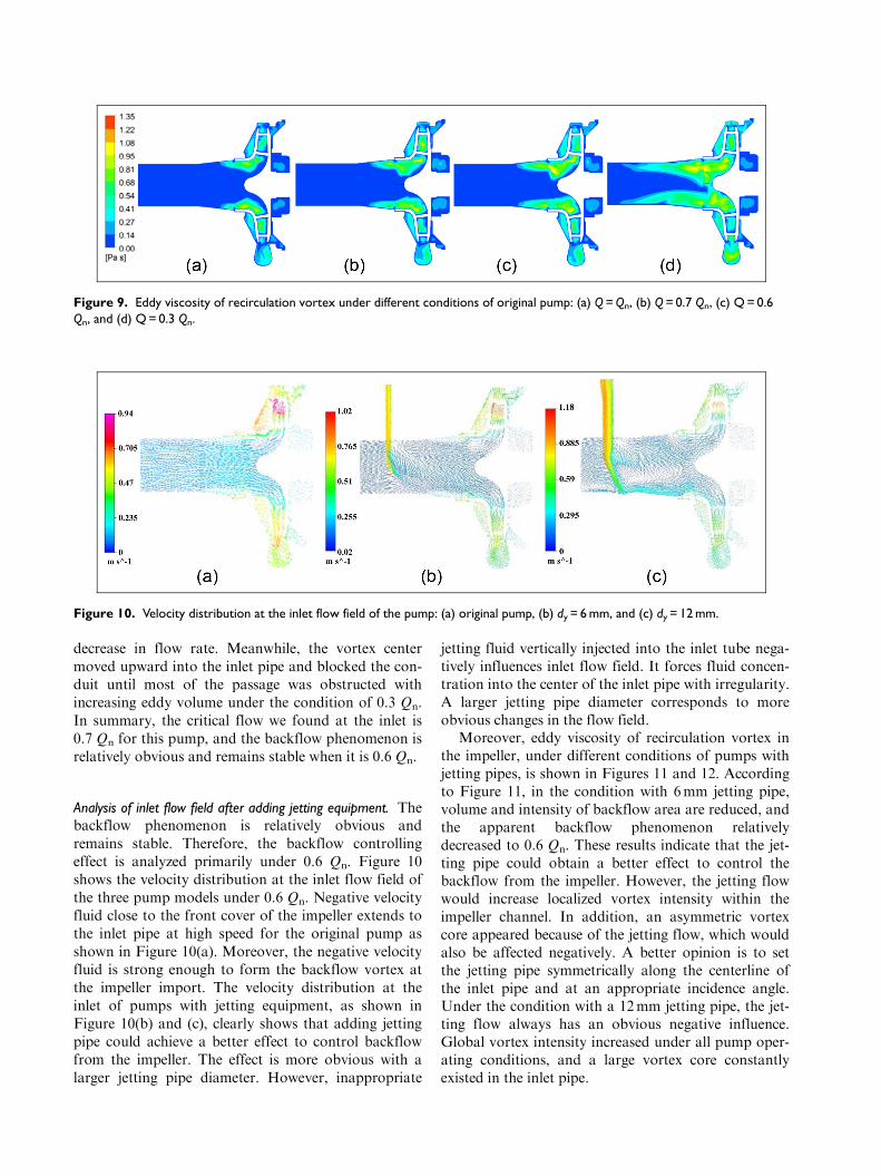
decrease in flow rate. Meanwhile, the vortex centermoved upward into the inlet pipe and blocked the con-duit until most of the passage was obstructed withincreasing eddy volume under the condition of 0.3 Qn.In summary, the critical flow we found at the inlet is0.7 Qn for this pump, and the backflow phenomenon isrelatively obvious and remains stable when it is 0.6 Qn.
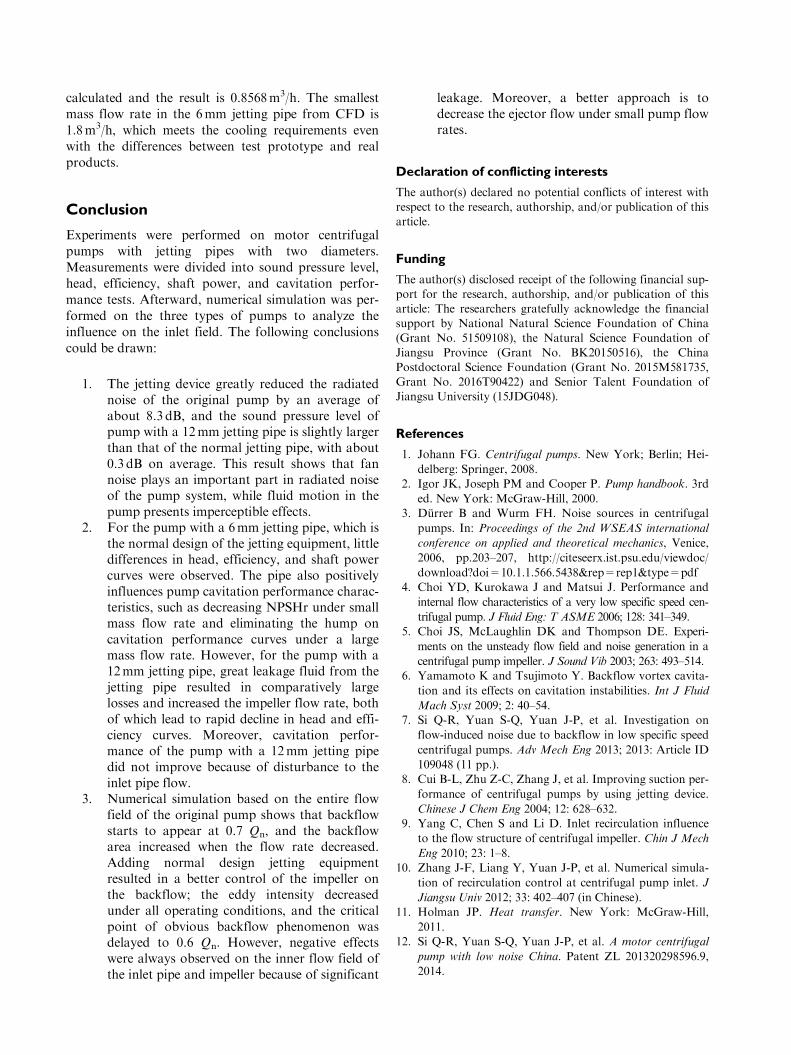
Analysis of inlet flow field after adding jetting equipment. Thebackflow phenomenon is relatively obvious andremains stable. Therefore, the backflow controllingeffect is analyzed primarily under 0.6 Qn. Figure 10shows the velocity distribution at the inlet flow field ofthe three pump models under 0.6 Qn. Negative velocityfluid close to the front cover of the impeller extends tothe inlet pipe at high speed for the original pump asshown in Figure 10(a). Moreover, the negative velocityfluid is strong enough to form the backflow vortex atthe impeller import. The velocity distribution at theinlet of pumps with jetting equipment, as shown inFigure 10(b) and (c), clearly shows that adding jettingpipe could achieve a better effect to control backflowfrom the impeller. The effect is more obvious with alarger jetting pipe diameter. However, inappropriate
jetting fluid vertically injected into the inlet tube nega-tively influences inlet flow field. It forces fluid concen-tration into the center of the inlet pipe with irregularity.A larger jetting pipe diameter corresponds to moreobvious changes in the flow field.
Moreover, eddy viscosity of recirculation vortex inthe impeller, under different conditions of pumps withjetting pipes, is shown in Figures 11 and 12. Accordingto Figure 11, in the condition with 6mm jetting pipe,volume and intensity of backflow area are reduced, andthe apparent backflow phenomenon relativelydecreased to 0.6 Qn. These results indicate that the jet-ting pipe could obtain a better effect to control thebackflow from the impeller. However, the jetting flowwould increase localized vortex intensity within theimpeller channel. In addition, an asymmetric vortexcore appeared because of the jetting flow, which wouldalso be affected negatively. A better opinion is to setthe jetting pipe symmetrically along the centerline ofthe inlet pipe and at an appropriate incidence angle.Under the condition with a 12mm jetting pipe, the jet-ting flow always has an obvious negative influence.Global vortex intensity increased under all pump oper-ating conditions, and a large vortex core constantlyexisted in the inlet pipe.
Figure 9. Eddy viscosity of recirculation vortex under different conditions of original pump: (a) Q = Qn, (b) Q = 0.7 Qn, (c) Q = 0.6Qn, and (d) Q = 0.3 Qn.
Figure 10. Velocity distribution at the inlet flow field of the pump: (a) original pump, (b) dy = 6 mm, and (c) dy = 12 mm.

Evaluation of the ejector flow rate. Finally, a necessary stepis to evaluate whether the ejector flow rate meets theneeds of the motor cooling and its influence on theinner flow. Figure 13 shows the ratio of the ejector flowaccount for the flow rate in the impeller under variousnon-dimensional mass flow rates from numericalresults. Figure 13 indicates that the percentage is toohigh for the pump with a 12mm jetting pipe, whichmainly caused the negative effect on the pump charac-teristics. For the ratio with a 6mm jetting pipe, it ismaintained within a reasonable range under large massflow rates, while remain high under small mass flowrates. Moreover, pumps under small mass flow ratesneed less cooling water for motor radiation. Therefore,installing a valve in the jetting pipe to control ejectorflow rate might be a convenient scheme.
The necessary ejector flow for motor cooling couldbe calculated using the following formula
q9=F9
rCmDto�ið3Þ
where Dto�i, the temperature difference between inletand outlet of the jetting equipment, is equal to 5�C.Then, necessary ejector flow rate, q#, could be
Figure 11. Eddy viscosity of recirculation vortex under different conditions of pumps with dy = 6 mm: (a) Q = Qn, (b) Q = 0.7 Qn, (c)Q = 0.6 Qn, (d) Q = 0.4 Qn, and (e) Q = 0.3 Qn.
Figure 12. Eddy viscosity of recirculation vortex under different conditions of pumps with dy = 12 mm: (a) Q = Qn, (b) Q = 0.7 Qn,(c) Q = 0.6 Qn, (d) Q = 0.4 Qn, and (e) Q = 0.3 Qn.
Figure 13. Flow percentage of the ejector flow.
calculated and the result is 0.8568m3/h. The smallestmass flow rate in the 6mm jetting pipe from CFD is1.8m3/h, which meets the cooling requirements evenwith the differences between test prototype and realproducts.
Conclusion
Experiments were performed on motor centrifugalpumps with jetting pipes with two diameters.Measurements were divided into sound pressure level,head, efficiency, shaft power, and cavitation perfor-mance tests. Afterward, numerical simulation was per-formed on the three types of pumps to analyze theinfluence on the inlet field. The following conclusionscould be drawn:
1. The jetting device greatly reduced the radiatednoise of the original pump by an average ofabout 8.3 dB, and the sound pressure level ofpump with a 12mm jetting pipe is slightly largerthan that of the normal jetting pipe, with about0.3 dB on average. This result shows that fannoise plays an important part in radiated noiseof the pump system, while fluid motion in thepump presents imperceptible effects.
2. For the pump with a 6mm jetting pipe, which isthe normal design of the jetting equipment, littledifferences in head, efficiency, and shaft powercurves were observed. The pipe also positivelyinfluences pump cavitation performance charac-teristics, such as decreasing NPSHr under smallmass flow rate and eliminating the hump oncavitation performance curves under a largemass flow rate. However, for the pump with a12mm jetting pipe, great leakage fluid from thejetting pipe resulted in comparatively largelosses and increased the impeller flow rate, bothof which lead to rapid decline in head and effi-ciency curves. Moreover, cavitation perfor-mance of the pump with a 12mm jetting pipedid not improve because of disturbance to theinlet pipe flow.
3. Numerical simulation based on the entire flowfield of the original pump shows that backflowstarts to appear at 0.7 Qn, and the backflowarea increased when the flow rate decreased.Adding normal design jetting equipmentresulted in a better control of the impeller onthe backflow; the eddy intensity decreasedunder all operating conditions, and the criticalpoint of obvious backflow phenomenon wasdelayed to 0.6 Qn. However, negative effectswere always observed on the inner flow field ofthe inlet pipe and impeller because of significant
leakage. Moreover, a better approach is todecrease the ejector flow under small pump flowrates.
Declaration of conflicting interests
The author(s) declared no potential conflicts of interest withrespect to the research, authorship, and/or publication of thisarticle.
Funding
The author(s) disclosed receipt of the following financial sup-port for the research, authorship, and/or publication of thisarticle: The researchers gratefully acknowledge the financialsupport by National Natural Science Foundation of China(Grant No. 51509108), the Natural Science Foundation ofJiangsu Province (Grant No. BK20150516), the ChinaPostdoctoral Science Foundation (Grant No. 2015M581735,Grant No. 2016T90422) and Senior Talent Foundation ofJiangsu University (15JDG048).
References
1. Johann FG. Centrifugal pumps. New York; Berlin; Hei-
delberg: Springer, 2008.2. Igor JK, Joseph PM and Cooper P. Pump handbook. 3rd
ed. New York: McGraw-Hill, 2000.3. Durrer B and Wurm FH. Noise sources in centrifugal
pumps. In: Proceedings of the 2nd WSEAS international
conference on applied and theoretical mechanics, Venice,
2006, pp.203–207, http://citeseerx.ist.psu.edu/viewdoc/
download?doi=10.1.1.566.5438&rep=rep1&type=pdf4. Choi YD, Kurokawa J and Matsui J. Performance and
internal flow characteristics of a very low specific speed cen-
trifugal pump. J Fluid Eng: T ASME 2006; 128: 341–349.5. Choi JS, McLaughlin DK and Thompson DE. Experi-
ments on the unsteady flow field and noise generation in a
centrifugal pump impeller. J Sound Vib 2003; 263: 493–514.6. Yamamoto K and Tsujimoto Y. Backflow vortex cavita-
tion and its effects on cavitation instabilities. Int J Fluid
Mach Syst 2009; 2: 40–54.7. Si Q-R, Yuan S-Q, Yuan J-P, et al. Investigation on
flow-induced noise due to backflow in low specific speed
centrifugal pumps. Adv Mech Eng 2013; 2013: Article ID
109048 (11 pp.).8. Cui B-L, Zhu Z-C, Zhang J, et al. Improving suction per-
formance of centrifugal pumps by using jetting device.
Chinese J Chem Eng 2004; 12: 628–632.9. Yang C, Chen S and Li D. Inlet recirculation influence
to the flow structure of centrifugal impeller. Chin J Mech
Eng 2010; 23: 1–8.10. Zhang J-F, Liang Y, Yuan J-P, et al. Numerical simula-
tion of recirculation control at centrifugal pump inlet. J
Jiangsu Univ 2012; 33: 402–407 (in Chinese).11. Holman JP. Heat transfer. New York: McGraw-Hill,
2011.12. Si Q-R, Yuan S-Q, Yuan J-P, et al. A motor centrifugal
pump with low noise China. Patent ZL 201320298596.9,
2014.

13. ISO 4412-1:1991. Hydraulic fluid power—test code fordetermination of airborne noise levels-part 1: pumps.
14. Tan L, Zhu B-S, Cao S-L, et al. Numerical simulation ofunsteady cavitation flow in a centrifugal pump at off-design conditions. Proc IMechE, Part C: J MechanicalEngineering Science 228: 1994–2006.
15. Tan L, Zhu B-S, Cao S-L, et al. Influence of prewhirl reg-ulation by inlet guide vanes on cavitation performance ofa centrifugal pump. Energies 7: 1050–1065.
16. Bolpaire S and Barrand JP. Experimental study of theflow in the suction pipe of a centrifugal pump at partialflow rates in unsteady conditions. J Press Vess: T ASME
1999; 121: 291–295.17. Li X-J, Yuan S-Q, Pan Z-Y, et al. Effects of the near-wall
mesh quality on the accuracy of numerical analysis incentrifugal pumps. Trans CSAE 2012; 28: 67–72 (inChinese).
18. Li X-J, Yuan S-Q, Pan Z-Y, et al. Numerical simulationof whole flow field for centrifugal pump with structuredgrid. Trans Chin Soc Agric Mach 2013; 44: 50–54 (inChinese).
19. Tan L, Zhu B-S, Wang Y-C, et al. Numerical study oncharacteristics of unsteady flow in a centrifugal pumpvolute at partial load condition. Eng Computation 32:1549–1566.
Appendix 1
Notation
Cm the specific heat capacity of water, 4200 J/kg�C
dy diameter of the jetting pipe
H pump headHn pump head at design flow ratel the length of helical water groovens specific speed of pumpNPSHr required net positive suction headP shaft powerPn shaft power at design flow ratePL energy loss of the motorq ejector flow rateQ pump flow rateQimp flow rate in pump impellerQj flow rate in jetting pipeQn pump design flow rateSPL sound pressure levelu2 circumferential velocity at the impeller
outlet, 26.42m/sv1 axial velocity of the main flow at the inlet
pipe
a the convective heat transfer coefficient,1200W/m2K
Dto�i temperature difference between inlet andoutlet of the jetting equipment, 5�C
DT temperature difference between water-jacket wall and water, 15�C
h pump efficiencyhn pump efficiency at design flow rater density of water, 1000 kg/m3
F# thermal energy from the motor