Embed Size (px)
Citation preview
State of California
Public Utilities Commission
Investigation Report on
PG&E Mission Substation Fire and Outage
December 20, 2003, San Francisco
** REDACTED **
Richard W. Clark, Director
Consumer Protection and Safety Division
October 20, 2004
ii
Table of Contents Executive Summary ................................................................................. 1
Chapter One: Chronology of Events....................................................... 9
Chapter Two: Findings and Recommendations.................................. 12
Physical Elements ................................................................................ 12
1. PILC Cable Failure.........................................................................................12
2. Smoke Detectors ...........................................................................................13
3. Bus Combustibility .........................................................................................13
4. Fire Barriers ..................................................................................................14
5. Auxiliary Bus Energizing ................................................................................14
6. SCADA Alarm Monitoring ..............................................................................15
7. Multitude of SCADA Alarms...........................................................................15
8. SCADA Inputs................................................................................................16
9. Relay Settings................................................................................................17
10. Fire Suppression..........................................................................................17
11. Ventilation .....................................................................................................18
12. Emergency Lighting .....................................................................................18
Institutional Elements............................................................................ 19
Operating Procedures:........................................................................ 19
13. Response to SCADA Alarms ........................................................................19
14. Staffing..........................................................................................................20
15. Smoke Filled Substation Policy.....................................................................20
16. Response to Loss of One Network Feeder (N-1) ..........................................21
Fire Coordination: ............................................................................... 22
17. Incident Command System (ICS)..................................................................22
18. Emergency Response Planning....................................................................23
19. PG&E and SFFD Communication.................................................................23
Management Tracking ........................................................................ 24
20. 1996 Fire Root Cause Analysis Report.........................................................24
iii
21. 1996 CES-Substations Fire Project Report...................................................25
22. Operations Standard UA 1465-Events and Investigations Procedures.........25
23. Technology Review.......................................................................................26
24. Restoration....................................................................................................26
25. Outage Communication ................................................................................27
26. Event Related Costs .....................................................................................27
Chapter Three: PG&E Electric Operations .......................................... 29
1. Golden Gate Control Center (GGCC)............................................. 29
2. San Mateo Transmission Control Center (SMCC).......................... 29
3. Transmission Operating Center (TOC)........................................... 30
Chapter Four: Mission Substation Facilities ...................................... 31
1. General Description of Mission Substation...................................... 31
2. SCADA ........................................................................................... 32
3. Transformers .................................................................................. 34
4. Distribution Feeders....................................................................... 34
5. Distribution Buses .......................................................................... 35
6. Switch Cabinets and Associated Equipment .................................. 37
7. Networks........................................................................................ 39
8. Electric System Protective Equipment............................................ 40
a. Circuit Breakers ..............................................................................................40
b. Relays.............................................................................................................41
c. Network Protectors.........................................................................................42
9. Fire Detection and Suppression System ........................................ 42
10. Ventilation System ....................................................................... 44
11. Emergency Lighting .................................................................... 44
Chapter Five: GGCC Operations .......................................................... 46
1. Staffing............................................................................................ 46
2. SCADA Alarm Monitoring................................................................ 48
iv
3. SCADA Alarm Response ................................................................ 50
Chapter Six: Fire Coordination............................................................. 53
1. Incident Command System (ICS)................................................... 53
2. Emergency Response Planning ..................................................... 54
3. Smoke Filled Substation Task Force.............................................. 57
Chapter Seven: Restoration ................................................................. 58
Chapter Eight: Outage Communication............................................... 59
Chapter Nine: 1996 Mission Substation Fire ....................................... 60
1. Description of the Event ................................................................. 60
2. 1996 Fire Root Cause Analysis...................................................... 61
3. Similarities to the 12/20/03 Event.................................................... 62
Chapter Ten: Management Overview Process .................................... 64
1. 1996 Fire Root Cause Analysis...................................................... 64
2. 1996 CES-Substation Fire Project Report...................................... 66
3. Operations Standard S1465 “Event Investigation Procedures” ...... 68
4. Technology Review........................................................................ 69
Chapter Eleven: Event Related Costs.................................................. 71
Chapter Twelve: Detailed Description of the Event ............................ 72
1. Cable Failure .................................................................................. 72
2. X-1153 Circuit Breaker Trip............................................................ 73
3. Ignition of the N bus ....................................................................... 73
4. Section E Circuit Breaker Trip ........................................................ 74
5. Initial Alarms .................................................................................. 75
6. Initial Operator Response .............................................................. 75
7. Power Problem Reported by Large Commercial Customer............ 76
8. Propagation of Fire Along the N Bus.............................................. 76
9. X-1109 & X-1162 Circuit Breakers Trip .......................................... 77
v
10. GGCC Response ......................................................................... 77
11. 1109/2 Circuit Breaker Reclosure ................................................ 78
12. Switchman Discovers Smoke....................................................... 78
13. San Francisco Fire Department Arrival ........................................ 79
14. Initial Restoration of Power .......................................................... 79
15. Discovery of Fire and Second Shutdown of Substation................ 79
16. Fire Damage ................................................................................ 81
17. Second and Final Restoration of Power ....................................... 84
ACRONYMS ............................................................................................ 86
Glossary.................................................................................................. 87
Appendix
vi
List of Figures and Tables Figure III-1. Areas served by Mission Substation.........................................................31
Figure III-2. Plan view showing a portion of the second floor switchgear area.............36
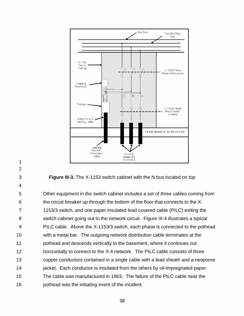
Figure III-3. The X-1153 switch cabinet with the N bus located on top .........................38
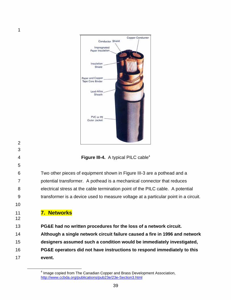
Figure III-4. A typical PILC cable .................................................................................39
Figure III-5. SCADA Screen Display ............................................................................49
Table XI-1. December 20 Mission Substation known fire related costs........................71
Figure XII-1. Damaged X-1153 cable ..........................................................................73
Figure XII-2. Damaged X-1153 cubicle........................................................................74
Figure XII-3. Cross section of substation underneath switch cubicle X-1101 ..............80
Figure XII-4. N-Bus fire damage ..................................................................................82
Figure XII-5. Fire damage X-1101 switch cubicle ........................................................83
Figure XII-6. Soot and debris on second floor switch room .........................................84
Appendix --------------------------------------------------------------------------------------------------------------------
--------------------------------------------------------------------------------------------------------------------
--------------------------------------------------------------------------------------------------------------------
Executive Summary 1 2
Background 3
4
On December 20, 2003, a fire in Pacific Gas and Electric Company’s (PG&E’s) 5
Mission Substation caused an outage to more than 100,000 customers 6
throughout San Francisco, including downtown retail stores filled with shoppers 7
on a peak holiday shopping weekend. There was substantial smoke, but the fire 8
that was the source of the smoke was not located for almost five hours. 9
10
PG&E did not call the San Francisco Fire Department (SFFD) until two hours 11
after the first signs of trouble at the Mission Substation. SFFD firefighters arrived 12
within minutes of being called, cleared the smoke, were unable to locate the fire 13
that was the source of the smoke, and PG&E restored service to about one-half 14
of its affected customers. Approximately one hour after service was restored to 15
these customers, PG&E located the fire, once again, interrupted service to the 16
customers it had just recently restored. The SFFD fought and extinguished the 17
fire and PG&E once again began the task of restoring service to all of its affected 18
customers. PG&E completed that task late in the evening of the next day. 19
20
The California Public Utilities Commission (CPUC) initiated an independent 21
investigation immediately following the incident. The team that was selected was 22
tasked with determining what happened, why it happened, and what could be 23
done to prevent or minimize a recurrence of this type of incident, at the Mission 24
Substation and any other indoor substations. 25
26
The CPUC’s Consumer Protection and Safety Division’s (CPSD) investigation 27
team worked independently, but collaboratively with PG&E personnel, and 28
monitored the content and status of PG&E’s investigation and related findings. 29
CPSD has also issued numerous requests for information (data requests) to 30
PG&E, conducted in-depth joint interviews of PG&E and SFFD personnel, and 31
2
conducted site inspections of the Mission Substation and the Golden Gate 1
Control Center (GGCC). 2
3
Soon after undertaking the investigation of the 2003 fire, CPSD discovered that 4
another fire had occurred at Mission Substation in 1996. CPSD’s investigation 5
team conducted a thorough analysis of both fires and found strikingly similar 6
contributing factors and root causes. CPSD’s team further determined that 7
PG&E had not implemented the recommendations resulting from its own 8
investigation of the 1996 fire. Key findings of the 2003/2204 investigation draw 9
heavily from the investigation of both events. 10
11
CPSD’s probing of the 1996 fire also caused PG&E to re-evaluate its own 12
investigation of that fire. As a result, PG&E concluded it had not adequately 13
followed through with recommendations from that investigation. CPSD finds it 14
quite troubling that PG&E did not implement its own recommendations from its 15
own investigation of the 1996 fire. 16
17
Description of Mission Substation 18
19
PG&E’s Mission Substation is a three-story concrete building with a basement 20
that serves customers in downtown San Francisco and parts of other districts 21
within the city. The substation receives power from 115 kilovolt (kV) 22
underground transmission lines. Transformers in the substation reduce the 23
transmission voltage to 4 kV and 12 kV distribution voltages. Power is distributed 24
to customers at this voltage through radial circuits and through network circuits 25
having multiple sources. 26
27
Since 1992, Mission Substation has been unattended and is controlled from the 28
Golden Gate Control Center (GGCC) in Daly City through a Supervisory Control 29
and Data Acquisition (SCADA) system that enables remote monitoring and 30
control of equipment. This includes monitoring of fire suppression equipment. 31
The substation has heat-activated sprinkler systems around oil-filled transformers 32
3
and high voltage circuit breakers for fire suppression, but has no fire suppression 1
or detection system for the medium voltage equipment on the second and third 2
floors. 3
4
Synopsis 5
6
At 3:51 p.m. on Saturday, December 20, 2003, a cable terminating in a switch 7
cabinet on the second floor of Mission Substation experienced a short circuit of 8
such magnitude as to cause the cable to explode. The circuit breaker protecting 9
the cable opened and de-energized the circuit. PG&E’s SCADA system 10
registered alarms at the GGCC, reporting the circuit breaker operation and 11
additional alarms that were caused by the cable failure. Because the cable was 12
one of a redundant set of cables to a network circuit, no customers lost power. 13
The explosion of the cable created smoke and vaporized debris, causing another 14
short circuit in the energized metal bars leading from the top of the switch cabinet 15
to the bus above the cabinet. The second short circuit ignited insulation around 16
the metal bus bars and caused a bus circuit breaker to open and de-energize the 17
burning bus. 18
19
PG&E personnel did not immediately investigate the alarms at Mission 20
Substation because there was no customer outage. However, the GGCC did 21
communicate the substation status to key PG&E management personnel. 22
23
At 5:24 p.m., the burning bus caused a short circuit in another switch cabinet, 24
resulting in an outage to 3,112 customers. 25
26
At 5:42 p.m., a switchman sent to Mission Substation to investigate the outage 27
reported smoke coming from the building. The GGCC updated PG&E 28
management on the conditions at Mission Substation. 29
30
At 5:57 p.m., all transmission breakers at Mission Substation were opened by 31
the San Mateo Control Center (SMCC), effectively de-energizing the substation 32
4
and terminating power to almost 100,000 PG&E customers, a loss of 150 MW or 1
22 percent of the load in San Francisco. 2
3
At 5:58 p.m. PG&E Gas Dispatch notified the SFFD of the fire at Mission 4
Substation and the SFFD entered the building minutes later. The SFFD vented 5
smoke from the building and found no fire source; PG&E re-energized the 6
transmission lines to the substation and began gradually restoring power to 7
customers. 8
9
At 9 p.m., while restoring power, PG&E discovered more smoke and the SFFD 10
found a fire on the first floor. After that fire was extinguished, the SFFD 11
discovered the bus fire in the second floor switch room that had ignited the first 12
floor fire. 13
14
At 10 p.m., Mission Substation was de-energized a second time to fight the fire 15
in the second floor switch room. As a result, 102,000 customers were without 16
power. 17
18
At 12:48 a.m., December 21, the substation was re-energized after the SFFD 19
extinguished the fire. PG&E then began damage assessment, repair, and power 20
restoration. By 11:45 p.m. power was restored to all customers supplied from the 21
Mission Substation. 22
23
Key Findings 24
25
CPSD’s investigation includes an analysis of how the equipment operated 26
immediately before and during the fire. We also examined how PG&E personnel 27
responded to the failure. There are 26 findings with recommendations related to 28
PG&E equipment, systems, and work processes and procedures. The following 29
comprise the major findings: 30
31
5
• The root cause of the incident was a cable failure in a switch 1
cabinet. The cable failed explosively, which caused a bus located 2
above it to catch on fire. Over time, vertically installed cable with 3
oil impregnated paper insulation loses its insulating capability 4
because the insulation dries out, resulting in a short circuit. 5
• The 1996 Mission Substation fire revealed that the insulation used 6
in the auxiliary buses is flammable and does not self extinguish, 7
but no steps were taken to mitigate this vulnerability. The auxiliary 8
bus above the switch cabinets was normally energized, so when 9
smoke and debris from a failed cable contaminated the air inside a 10
switch cabinet, arcing occurred and ignited the flammable bus 11
insulation. 12
• PG&E failed to follow three recommendations made in its 1996 13
Root Cause Analysis Report following its 1996 fire. At that time, 14
PG&E did not have a formal management review process to track 15
recommendations from root cause investigations. Had PG&E 16
implemented its 1996 investigation recommendations, CPSD 17
believes the cable failure on December 20, 2003 would not have 18
resulted in loss of service to customers. 19
• PG&E operators did not have user-friendly SCADA screen displays 20
or knowledge of operating procedures that prioritize audible, 21
miscellaneous, and critical alarms that originated at Mission 22
Substation. With over 1,800 alarms received a day at the GGCC, 23
PG&E operators overlooked some alarms. Further, the GGCC did 24
not have written operating procedures for addressing alarms, so 25
operators had to rely on personal knowledge and experience to 26
respond. 27
• PG&E had no written procedures for the loss of a network circuit. 28
Although a similar network circuit failure caused the fire in 1996 29
and network designers assumed such a condition would be 30
6
immediately investigated, PG&E operators did not have 1
instructions to respond immediately to this event. 2
• PG&E had no written plan or procedures for coordinating 3
emergency fire responses at indoor substations. The SFFD did 4
not know who the PG&E person-in-charge was until four hours 5
after the first SCADA alarm. Lack of coordination contributed to 6
the delays in locating the fire and caused additional damage to 7
equipment and substantial delays in restoring power to customers. 8
7
Recommendations 1
2
CPSD’s recommendations include an analysis of how the equipment operated 3
immediately before and during the fire and how PG&E personnel responded. 4
The analysis led to conclusions on origin and propagation of the fire, operating 5
procedures, fire coordination, as well as other organizational and cultural issues. 6
We categorized findings as “physical” for findings that are equipment or systems 7
related, and “institutional” for findings that are process or procedure related. 8
9
Recommended improvements resulting from the physical findings include: 10
11
1. Replace old, vertically installed, oil-impregnated paper insulated cables. 12
2. De-energize auxiliary distribution buses and conduct periodic testing. 13
3. Install smoke detection system and connect it to SCADA. 14
4. Improve SCADA monitoring interface at the control center. 15
16
Recommended improvements resulting from the institutional findings include: 17
18
• Provide written procedures and related training for responding to 19
specific SCADA alarms. 20
• Ensure sufficient staffing is immediately available for investigation 21
of circuit breaker alarms. 22
• Develop an emergency plan including coordination and 23
communication with the fire department. 24
• Ensure executive management accountability for the evaluation 25
and implementation of recommendations resulting from 26
investigations and inspections. 27
8
• Establish methods to evaluate and implement new technologies 1
and methods that can improve the safety, reliability, and 2
effectiveness of system design, equipment, and procedures. 3
• Periodically report to the CPUC the status of the evaluation and 4
implementation of all recommendations made herein until all 5
recommendations have been addressed. 6
7
Investigation Report 8
9
This report contains, hereinafter: 10
• Chronology of Events—A detailed timeline of events during the 11
incident. 12
• Findings and Recommendations—Analysis of the root cause of the 13
fire and the reason for PG&E’s slow response to both the fire and 14
customer restoration. Recommendations pertain to each listed 15
cause and key finding. Some recommendations not only apply to 16
Mission Substation but to the entire PG&E electric distribution 17
system. 18
• Background—An overview of Mission Substation and related 19
equipment and systems, and a description of operations. 20
• 1996 Mission Substation Fire—An overview of the event describing 21
physical similarities with the 2003 fire, recommendations of 22
PG&E’s 1996 Root Cause Analysis Report, and identification of 23
common issues that impacted both events. 24
• Detailed Description of the Event—An account of the incident 25
including technical details regarding what equipment failed, how 26
other equipment was damaged, and how the fire was started, 27
found, and extinguished. 28
• Appendices—A compilation of technical details, PG&E reports, and 29
independent lab tests. 30
9
Chapter One: Chronology of Events 1 2
This section is a chronology of the significant events in the Mission Substation 3
fire, from initial event to service restoration. Some time periods have been 4
estimated based on the best available data. 5
6
Saturday, December 20, 2003 7
8
• 3:51 p.m. 9
The X-1153 12 kV cable short-circuited. The failure caused the X-10
1153 circuit breaker to open and a SCADA1 alarm activated at the 11
Golden Gate Control Center (GGCC). The operator at the GGCC 12
did not send anyone to the substation to investigate the cause of 13
the circuit breaker operation. 14
• 5:24 p.m. 15
The circuit breakers protecting the X-1109 and X-1162 cables 16
opened automatically on short circuit. These were the second and 17
third circuits lost since the initial X-1153 breaker alarms. A 18
switchman was sent to the substation to investigate. 19
• 5:42 p.m. 20
The switchman arrived at the substation and noticed smoke coming 21
from the ventilation system. He opened both entrances to the 22
substation, discovered heavy smoke, and communicated the 23
situation to the GGCC. 24
• Between 5:42 p.m. and 5:55 p.m. 25
The GGCC operator notified various agencies and individuals of the 26
problem at Mission Substation. They included PG&E’s San 27
Francisco Gas Dispatch, the San Mateo Control Center (SMCC), 28
the CPUC incident hot line, PG&E news department, substation 29
maintenance on call supervisor and other PG&E personnel. The 30
1 SCADA is an acronym standing for supervisory control and data acquisition. See section III.A.11 for a description of the Mission substation SCADA system.
10
GGCC operator requested that the SMCC de-energize Mission 1
Substation so that the fire department could safely fight the fire. 2
• 5:57 p.m. 3
The SMCC opened the transmission breakers and de-energized 4
the substation; this interrupted service to about 100,000 customers. 5
• 5:58 p.m. 6
PG&E San Francisco Gas Dispatch called the San Francisco Fire 7
Department (SFFD). 8
• 6:05 p.m. 9
The SFFD arrived at Mission substation. Firefighters using a 10
thermal imaging camera entered the building to search for possible 11
victims. They found no victims or source of smoke. 12
• Between about 6:05 p.m. and 7:30 p.m. 13
Firefighters cleared smoke from the building with portable fans and 14
did not find a fire. 15
• Between 7:46 p.m. and 7:49 p.m. 16
SMCC reenergized the substation. 17
• 7:48 p.m. 18
PG&E personnel restored power to the substation ventilation fans 19
to assist in clearing smoke from the building. 20
• 8:26 p.m. to 8:50 p.m. 21
PG&E re-energized satellite substations from Mission Substation, 22
thereby restoring power to 49,600 customers. 23
• 9 p.m. 24
PG&E employees discovered fire in the foreman’s office2 and 25
notified the SFFD, which was in the process of leaving the 26
substation. 27
• 9 p.m. to 9:36 p.m. 28
The SFFD extinguished the fire in the first floor foreman’s office, but 29
smoke persisted. 30
2 The foreman’s office is adjacent to the control room.
11
• Between 10 p.m. and 10:16 p.m. 1
The GGCC operator ordered the opening of all distribution circuit 2
breakers and the SMCC opened all transmission circuit breakers. 3
This de-energized the substation a second time. Again, service 4
was interrupted to the 49,600 customers previously restored plus 5
2,600 additional customers supplied by a satellite station through 6
Mission Substation. Approximately 102,000 customers were 7
without power. 8
• 10:11 p.m. 9
The SFFD discovered a fire burning on the 2nd floor. 10
11
Sunday, December 21, 2003 12
13
• Between 10:11 p.m. on December 20 and 12:59 a.m. on December 21 14
The SFFD extinguished the fire on the second floor. 15
• 12:48 a.m. 16
PG&E restored power to the substation from the transmission lines. 17
• Between 1:20 a.m. and 1:56 a.m. 18
PG&E reenergized satellite substations and restored power to 19
49,600 customers. 20
• Between 2:07 a.m. and 6:44 a.m. 21
PG&E restored service to another 29,500 customers. 22
• Between 6:44 a.m. and 11:45 p.m. 23
PG&E personnel cleaned switch cubicles and restored them to 24
service. 25
• 11:45 p.m. 26
All customers were restored to service. 27
12
Chapter Two: Findings and Recommendations 1 2
There are 26 findings with recommendations relating to PG&E equipment, 3
systems, and work processes and procedures. Key findings are categorized as 4
“physical” for findings that are equipment or systems related and “institutional” for 5
findings that are process or procedures related. “Status” of recommendations 6
refers to actions PG&E has already taken to implement its own 7
recommendations. 8
9
Physical Elements 10 11
1. PILC Cable Failure 12 13
Finding: 14
The root cause of the incident was a cable failure in a switch 15
cabinet. The cable failed explosively, which caused a bus 16
located above it to catch on fire. Over time, vertically 17
installed cable with oil impregnated paper insulation loses its 18
insulating capability because the insulation dries out, 19
resulting in a short circuit. 20
Recommendations: 21
PILC cables of similar age and physical arrangement at 22
Mission and other indoor substations may be near failure. 23
1. Replace all vertical runs of PILC cable at Mission 24
substation. 25
2. Identify and replace similar vertical runs of PILC cables at 26
other indoor substations unless PG&E can demonstrate 27
through testing or other means that the probability of 28
cable failure is low. 29
Status: 30
PG&E has replaced 22 vertical runs of PILC cable at 31
Mission substation. PG&E completed work on 3/30/2004. 32
33
13
2. Smoke Detectors 1 2
Finding: 3
There were no smoke detectors at Mission substation at the 4
time of the December 20, 2003 incident despite earlier 5
recommendations by PG&E to install them in certain areas. 6
Recommendation: 7
Install smoke detectors at Mission substation covering areas 8
with energized equipment to provide for early warning of a 9
fire. The smoke detectors need to be connected to SCADA 10
to provide the GGCC with indication of a fire in the 11
substation. 12
Status: 13
PG&E expects smoke detection will be operational by 14
11/30/2004. 15
16
3. Bus Combustibility 17 18
Finding: 19
The insulation of the 12 kV distribution auxiliary buses is 20
composed of flammable material. Once ignited, the bus 21
insulation continued to spread and burn. The flammable 22
insulation caused both the 1996 and 2003 fires to spread 23
along the bus duct and damage more switch cabinets. 24
Recommendation: 25
Bus combustibility must be considered in a switchgear 26
replacement program. Measures must be taken to reduce 27
or eliminate conditions that would ignite the insulation. 28
Status: 29
PG&E expects to add combustibility criteria by 11/1/2004. 30
Presently, PG&E has de-energized the auxiliary buses. 31
32
14
4. Fire Barriers 1 2
Finding: 3
Switch cubicle openings did not have barriers to contain 4
smoke. In both the 1996 and 2003 incidents, smoke flowing 5
through cubicle openings caused arcing between exposed, 6
live electrical parts that ignited a fire. 7
Recommendation: 8
Seal switch cubicle openings. 9
Status: 10
PG&E completed penetration-sealing work on 6/3/2004. 11
12
5. Auxiliary Bus Energizing 13 14
Finding: 15
Both the 1996 and 2003 fires propagated beyond the fault 16
because a short circuit arc on the N bus ignited the bus 17
insulation. The arc occurred because the bus was 18
energized. The bus was normally energized as a standby 19
power source for the distribution switches. 20
Recommendation: 21
Energize the auxiliary buses only when they are needed. 22
Perform periodic tests on the buses by energizing them to 23
ensure the buses are operational when needed as an 24
alternate source of power. 25
Status: 26
The M and N auxiliary buses have been de-energized as a 27
normal operating condition at Mission Substation. PG&E is 28
currently evaluating regular auxiliary bus testing. 29
15
6. SCADA Alarm Monitoring 1 2
Finding: 3
PG&E operators do not have user-friendly SCADA screens 4
and interface that enable them to effectively monitor and 5
respond to SCADA alarms and conditions. 6
Recommendation: 7
1. Study and redesign SCADA screen to improve response 8
to alarms. 9
2. Ensure audible alarms are acknowledged individually. 10
3. Ensure audible alarms are silenced manually and are not 11
automatically deleted after a time limit. 12
Status: 13
PG&E is studying SCADA screen presentation and plans to 14
complete this by 5/31/05. Following the incident, PG&E 15
implemented new procedures to include: 16
1. Dedicated computer monitor just for the SCADA alarm 17
log, 18
2. Removal of bulk alarm acknowledgement, 19
3. Increased volume of the audible alarms, 20
4. Removal of automatic silence of an audible alarm, and 21
5. Standardized configuration for SCADA alarm display 22
screens. 23
24 7. Multitude of SCADA Alarms 25
26 Finding: 27
The GGCC district operators cannot recognize, prioritize, 28
and respond effectively when a large number of SCADA 29
alarms arrive in a short period of time. This is why 30
operators did not respond to the initial X-1153 and fire 31
subsystem audible alarms. 32
16
Recommendation: 1
1. Create reporting and prioritizing criteria for all audible, 2
miscellaneous, and critical alarms and status alerts that 3
enables the operator to quickly assess them and 4
respond effectively. 5
2. Verify the legitimacy of all SCADA alarms to eliminate 6
unnecessary alarms. 7
Status: 8
In January 2004, PG&E published Substation Engineering 9
Bulletin IB0211 that defined SCADA alarm types and alarm 10
categories and the visual presentation of the alarms on the 11
display screen. Additionally, PG&E modified equipment 12
settings to improve the criteria used to determine the 13
necessity for an alarm, thereby eliminating conditions that 14
correct themselves and reducing the number of alarms. 15
PG&E is studying existing alarms monitored by the GGCC 16
and expects to complete work by 5/31/05. 17
18
8. SCADA Inputs 19 20
Finding: 21
SCADA has a single nonspecific alarm for the many 22
auxiliary bus breakers, preventing an operator from 23
determining which breaker generated the alarm. 24
Recommendation: 25
Ensure that each bus breaker is individually monitored by 26
SCADA. 27
Status: 28
PG&E is evaluating additional SCADA input from 12 kV 29
relays and breakers. 30
17
9. Relay Settings 1 2
Finding: 3
The 1162 circuit breaker tripped on reverse current when 4
the voltage on the Section H bus fell to close to zero as the 5
result of the fault in the X-1109 cubicle. The instantaneous 6
units in the circuit breaker’s overcurrent relays initiated the 7
trip. Opening of the circuit breaker under these conditions is 8
undesirable because it could unnecessarily cause 9
customers to lose power. 10
Recommendation: 11
Disable the instantaneous units on relays in feeders to 12
networks. 13
Status 14
PG&E has initiated a study to review relay settings and 15
schemes for indoor substations network systems. The study 16
is expected to be completed by 10/1/2005. 17
18
10. Fire Suppression 19 20
Finding: 21
Fire suppression equipment is adequate at Mission 22
Substation, but it can be improved in key areas consistent 23
with recommendations in PG&E’s 1996 CES Substations 24
Fire Project Report. 25
Recommendation: 26
1. Provide suppression protection for the basement, sub-27
basement area, and potheads as itemized in the 1996 28
CES-Substation Fire Project Report. 29
2. Ensure that deficiencies noted in system inspections are 30
corrected and tracked in a timely manner. 31
18
Status: 1
Area-wide sprinklers are not installed for the potheads, 2
basement cable spreading room, or sub-basement area at 3
Mission Substation. Providing protection in the remainder of 4
the basement and for the potheads is being considered. 5
PG&E expects that evaluation will be completed by 6
7/31/2004. 7
8
11. Ventilation 9 10
Finding: 11
Roof fans can only be turned on manually at the fan 12
location. The SFFD needed the fans to ventilate the 13
building and were forced to use a ladder truck to access the 14
building roof to operate the fans. 15
Recommendations: 16
Install remote controls for the roof fans and all other fans in 17
the substation at a central, easily accessible location known 18
to the SFFD. 19
Status: 20
PG&E expects to complete work by 12/31/2004. 21
22
12. Emergency Lighting 23 24
Finding: 25
The SFFD Rescue Squad Chief stated that there was no 26
lighting in the substation when he was there. However, 27
there is a minimum of emergency lighting powered by the 28
station battery that automatically turns on when power is 29
lost in the substation. When the rescue squad was in the 30
building, the dense smoke likely diminished the intensity of 31
the emergency lighting. 32
19
Recommendation: 1
Test the substation emergency lighting to identify all areas 2
for which back up lighting is insufficient to facilitate a safe 3
exit from the building during emergency conditions. Install 4
additional or alternative lighting solutions for all areas 5
identified. 6
Status: 7
PG&E is currently evaluating the use of additional 8
emergency lighting at indoor substations and expects to 9
complete plans by 12/31/05. 10
11 Institutional Elements 12
13 Operating Procedures: 14
15 13. Response to SCADA Alarms 16
17 Finding: 18
GGCC relied heavily on the individual knowledge and 19
experience of operators in responding to specific SCADA 20
alarms and system conditions. This contributes to 21
inconsistent and possibly inefficient responses to 22
emergencies. 23
Recommendation: 24
Establish written procedures and train staff to assess and 25
provide immediate response to system emergencies. The 26
procedures need to include responsibilities for the district 27
management. 28
Status: 29
PG&E expects completion of operating procedures and 30
training by 12/31/2005. 31
20
14. Staffing 1 2
Finding: 3
On weekday nights and weekends, staffing is reduced. In 4
the event of a potentially serious event such as fire or 5
multiple outages occurring during those times, delays in 6
obtaining appropriate on-call staffing could cause 7
consequences more severe than during a typically staffed 8
weekday. 9
Recommendation: 10
1. Review staffing levels during after-hours and weekends to 11
improve response to system emergencies. 12
2. Develop written procedures to assign responsibilities for 13
district management to respond to emergencies outside of 14
normal working hours. 15
Status: 16
PG&E expects to complete a review of staffing requirements 17
by 12/31/2005. 18
19 15. Smoke Filled Substation Policy 20
21 Finding: 22
According to a 2003 bulletin, PG&E employees are not 23
allowed to enter smoke-filled substations. Prior to the 24
December 20, 2003 event, PG&E did not initiate 25
discussions with the SFFD about specific details in the 26
bulletin. 27
Recommendation: 28
PG&E and the SFFD should develop joint policy to support 29
SFFD personnel working inside substations and incorporate 30
decisions into existing operating procedures. 31
21
Status: 1
PG&E expects to review the existing bulletin and will finalize 2
procedures by 11/30/04. 3
4 16. Response to Loss of One Network Feeder (N-1) 5
6 Finding: 7
PG&E had no written procedures for the loss of a network 8
circuit. Although a single network circuit failure caused a 9
fire in 1996 and network designers assumed such a 10
condition would be immediately investigated, PG&E 11
operators did not have instructions to respond immediately 12
to this event. 13
Recommendation: 14
Establish written procedures and standards for GGCC, 15
Substation management, System designers, and District 16
Operations, Maintenance and Construction (OM&C) 17
management to follow in (N-1) or greater occurrences. 18
Status: 19
In May 2004, PG&E issued a bulletin (2004PGM-6: 20
Procedures for Tie-Cable and Network Feeder Failures) to 21
all key personnel with specific instructions for immediate 22
response to the loss of a single network feeder (N-1). The 23
bulletin included interim procedures for the loss of two 24
network feeders while PG&E creates a separate bulletin for 25
that condition (N-2). PG&E expects to finalize written 26
operating procedures by 12/31/04. 27
28
22
Fire Coordination: 1 2
17. Incident Command System (ICS) 3 4
Finding: 5
1. The SFFD did not know who the PG&E person-in-charge 6
was until four hours after the first SCADA alarm. 7
2. PG&E did not have any written procedures that define 8
this role when PG&E personnel respond to trouble at an 9
unattended substation. 10
3. PG&E and SFFD had no prior agreements about how a 11
proposed Incident Command System (ICS) would 12
operate during a substation fire emergency. 13
Recommendation: 14
1. In collaboration with the SFFD, confirm roles and 15
responsibilities of PG&E Person-in Charge (PIC) for 16
substation events and develop related written 17
procedures. 18
2. Investigate how PG&E command structure at a field 19
substation complements the SFFD Incident Command 20
System. 21
3. Train first responders (e.g., Troublemen, Cablemen, 22
Electricians) to manage response with PG&E PIC and 23
SFFD Incident Commander. 24
Status: 25
PG&E and SFFD conducted several meetings in the spring 26
and summer of 2004 to discuss fire coordination issues. 27
PG&E expects to finalize procedures by 12/31/05. 28
29
23
18. Emergency Response Planning 1 2
Finding: 3
PG&E and SFFD personnel were not guided by an agreed 4
upon joint emergency response plan as recommended in 5
the April 1996 CES-Substations Fire Project Report. This 6
plan would provide information critical to firefighters during 7
an emergency, such as maps, a list of hazards, emergency 8
numbers, and locations of ventilation switches. 9
Recommendation: 10
1. Complete the joint emergency response plan with SFFD 11
and meet with SFFD personnel at least once a year to 12
review and update. 13
2. Decide location and owner of a Master Plan for each 14
indoor substation in the Bay Area. 15
3. Conduct periodic walkthroughs and emergency drills to 16
ensure up-to-date training of all personnel. 17
Status: 18
A proposed emergency response plan for Mission 19
Substation is nearly complete. It will be used as a model to 20
complete other joint emergency plans for other indoor 21
stations by this fall. PG&E expects to complete emergency 22
response plans for all indoor substations by 12/31/05. 23
24
19. PG&E and SFFD Communication 25 26
Finding: 27
Between the 1996 and 2003 Mission Substation fires, PG&E 28
and the SFFD have had little communication on common 29
issues and concerns. This resulted in ineffective substation 30
fire response. 31
24
Recommendation: 1
1. Conduct joint PG&E and SFFD meetings to address lack 2
of pre-planning, emergency response, communication, 3
and training pertaining to fire response. 4
2. Develop process to ensure ongoing management 5
supervision of activities and tracking of emergency 6
action plans. 7
Status: 8
PG&E and SFFD conducted several meetings in the spring 9
and summer of 2004 to discuss fire coordination issues. 10
PG&E expects to finalize procedures by 12/31/05. 11
12
Management Tracking 13 14
20. 1996 Fire Root Cause Analysis Report 15 16
Findings: 17
1. PG&E failed to implement three recommendations made 18
in its 1996 root cause analysis report. 19
2. At that time, PG&E did not have a formal management 20
overview process to track recommendations from root 21
cause investigations. 22
3. Had PG&E implemented the 1996 investigation 23
recommendations, CPSD believes the cable failure on 24
December 20, 2003 would not have resulted in an 25
outage to more than 100,000 customers throughout San 26
Francisco. 27
Recommendation: 28
Establish and enforce formal management tracking system 29
to monitor incident root cause recommendations. For 30
incidents with a significant public impact, meet with CPUC 31
quarterly to discuss progress. 32
25
Status: 1
PG&E has named a project manager accountable to the 2
Vice-President of Operations, Maintenance and 3
Construction (OM&C) to ensure that root cause analysis 4
recommendations are implemented and that results are 5
regularly communicated to the CPUC. 6
7
21. 1996 CES-Substations Fire Project Report 8 9
Finding: 10
At the time of the 1996 fire, PG&E did not take action to 11
improve fire detection and suppression in indoor substations 12
that was recommended in the report. 13
Recommendation: 14
Re-evaluate the contents of the 1996 CES-Substations Fire 15
Project Report and implement recommendations based on 16
the outcome of the analysis. 17
Status: 18
PG&E is currently studying and implementing various 19
recommendations contained in the report. 20
21
22. Operations Standard UA 1465-Events and 22 Investigations Procedures 23 24
Finding: 25
PG&E has a slow and cumbersome process to review 26
operating standards relating to incident investigation 27
procedures. 28
Recommendation: 29
1. Complete review and approval of a revised draft of UO 30
Standard S1465 that improves event investigation 31
procedures for electric utility operations by 12/31/04. 32
26
2. Establish stringent deadlines for ongoing approval and 1
distribution of revised standards that pertain to safety 2
and reliability related areas. 3
Status: 4
As of April 15, 2004, PG&E is reviewing the standard but 5
has no estimate of when the final revision will be reviewed 6
or approved. 7
8
23. Technology Review 9 10
Finding: 11
PG&E has no systematic procedure to review and adopt 12
new technology that can improve safety and reliability. 13
Examples of technology related to this incident include 14
barrier seal material and laser beam smoke detector 15
technology for indoor substations. 16
Recommendation: 17
Implement a formalized process to ensure that current or 18
state–of-the-art technology solutions are researched and 19
recommended for safety and reliability concerns. 20
Status: 21
Following the December 20, 2003 incident, PG&E began to 22
investigate alternative barrier seal material and laser beam 23
smoke detector technologies for Mission Substation. 24
25
24. Restoration 26 27
Finding: 28
PG&E has no written restoration guidelines for Mission 29
Substation and other substations. Reporting discrepancies 30
existed regarding total number of customers affected during 31
the course of the incident. 32
27
Recommendation: 1
1. Develop written restoration guidelines for all indoor 2
substations with networks and tie cables. 3
2. Improve accuracy of Outage Information System (OIS) by 4
implementing needed programming changes. 5
Status: 6
PG&E expects to implement guidelines by 12/31/2004. 7
8
25. Outage Communication 9 10
Finding: 11
Estimated Time of Recovery (ETOR) was underestimated 12
during the incident resulting in overoptimistic feedback to 13
customers about when their service would be restored. 14
Recommendation: 15
Continue to improve ETOR communication process 16
pertaining to indoor substations and train personnel 17
accordingly. 18
Status: 19
PG&E expects to complete guidelines by 12/31/04. 20
21
26. Event Related Costs 22 23
Finding: 24
PG&E and ratepayers would have saved millions of dollars 25
if the fire had been detected sooner, resulting in less 26
damage to the substation and a less extensive power 27
outage. 28
Recommendation: 29
Review PG&E and CPUC investigation reports and 30
implement recommendations in a timely manner to ensure 31
that a similar incident does not happen again. 32
28
Status: 1
PG&E has named a project manager accountable to the 2
Vice-President of Operations, Maintenance and 3
Construction (OM&C) to ensure that action plans relating to 4
the incident are implemented and that results are regularly 5
communicated to the CPUC. 6
29
Chapter Three: PG&E Electric Operations 1 2
The control centers, including Golden Gate Control Center (GGCC), San Mateo 3
Transmission Control Center (SMCC), and Transmission Operating Center 4
(TOC) were involved in various aspects of the December 20, 2003 event. This 5
chapter covers a brief description of those control centers. 6
7
1. Golden Gate Control Center (GGCC) 8 9
----------------------------------------------------------------------------------------------------------- 10
----------------------------------------------------------------------------------------------------------- 11
------------------------------------------------------------------------------------------------------------12
------------------------------------------------------------------------------------------------------------13
------------------------------------------------------------------------------------------------------------14
------------------------------------------------------------------------------------------------------------15
------------------------------------------------------------------------------------------------------- 16
17
------------------------------------------------------------------------------------------------------------18
------------------------------------------------------------------------------------------------------------19
------------------------------------------------------------------------------------------------------------20
------------------------------------------------------------------------------------------------------------21
------------------------------------------------------------------------------------------------------- 22
23
2. San Mateo Transmission Control Center (SMCC) 24 25
------------------------------------------------------------------------------------------------------------26
------------------------------------------------------------------------------------------------------------27
--------------------------------------------------------------------------------------------------------- 28
29
------------------------------------------------------------------------------------------------------------30
------------------------------------------------------------------------------------------------------------31
------------------------------------------------------------------------------------------------------------32
-------------------------------------------------------------------------------------------------------- 33
30
----------------------------------------------------------------------------------------------------------- 1
------------------------------------------------------------------------------------------------------------2
------------------------------------------------------------------------------------------------------------ 3
4
3. Transmission Operating Center (TOC) 5 6
------------------------------------------------------------------------------------------------------------7
------------------------------------------------------------------------------------------------------------8
------------------------------------------------------------------------------------------------------------9
------------------------------------------------------------------------------------------------------------10
------------------------------------------------------------------------------------------------------------11
------------------------------------------------------------------------------------------------------------12
------------------------------------------------------------------------------------------------------------13
---------------------------------------------------------------------------------------------------- 14
15
31
Chapter Four: Mission Substation Facilities 1 2
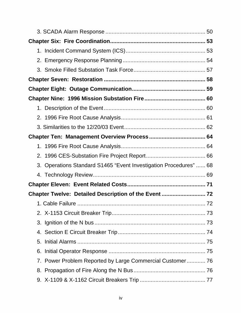
1. General Description of Mission Substation 3 4
Mission Substation is an indoor substation contained in a three-story concrete 5
structure with a basement3. The substation is located at the corner of Mission 6
and 8th Street in downtown San Francisco. It provides power to approximately 7
100,000 customers. The area served by the substation is shown in Figure III-1, 8
below. 9
10 11 12
13
14
15
16
17
18
19
20
21
22
23
24
25
26
Figure III-1. Areas served by Mission Substation. 27
28
Electrical power engineers, operators and maintenance personnel use what is 29
known as a single line diagram to represent the arrangement of the components 30
that make up the electrical network. A simplified single line diagram representing 31
3 Mission substation has been in service since 1948
32
Mission Substation is shown in Appendix A. Refer to the single line diagram to 1
see how the elements of the substation described below fit together. 2
3
------------------------------------------------------------------------------------------------------------4
------------------------------------------------------------------------------------------------------------5
------------------------------------------------------------------------------------------------------------6
------------------------------------------------------------------------------------------------------------7
------------------------------------------------------------------------------------------------------------8
------------------------------------------------------------------------------------------------------------9
------------------------------------------------------------------------------------------------------------10
------------------------------------------------------------------------------------------------------------11
------------------------------------------------------------------------------------------------------------12
------------------------------------------------------------------------------------------------------------13
------------------------------------------------------------------------------------------------------------14
------------------------------------------------------------------------------------------------------------15
----------------------------------------------------------------------------------------------- 16
17
2. SCADA 18 19
The SCADA system is PG&E’s connection to the unattended Mission Substation. 20
SCADA enables the control centers to remotely monitor and control system 21
equipment such as voltage regulators, breakers, and switches. Both the 22
transmission and distribution control centers utilize SCADA to view and access 23
Mission Substation. Continuous and alert SCADA monitoring is critical to the 24
safe, efficient, and reliable operation of its electrical system. 25
26
At the substation, SCADA operates through Remote Terminal Units (RTUs). The 27
RTUs receive data through connections to every piece of equipment that needs 28
remote management. The information consists of such data as voltage, current, 29
breaker positions, and other equipment specific data. The RTUs also provide 30
communication to equipment. Commands sent through RTUs include 31
adjustments of voltage levels and operation of circuit breakers and switches. All 32
33
distribution and transmission circuits have some level of remote management 1
capability. 2
3
The RTUs also monitor information not pertaining to circuits. Emergency battery 4
backup power for the RTUs is monitored in case the substation loses main 5
power. The substation fire control system is also connected to the RTUs. 6
SCADA receives data on fire system problems, heat detectors, fire system 7
activation, and fire alarm activation. 8
9
At the control centers, SCADA operates through master computer stations, used 10
by system operators to remotely manage the transmission and distribution 11
system. Master stations receive all of the information gathered by the RTUs. 12
Operators use graphical user interfaces, text log displays, and command line 13
inputs to view and operate substation equipment. 14
15
When problems arise or conditions change in system equipment, the master 16
stations report alarms. The alarms are displayed and categorized as “critical”, 17
“status”, or “miscellaneous”. Fire alarms and breakers are critical; relays and 18
voltage levels are status; non-critical and fire system problems (not activation) 19
are miscellaneous. 20
21
Although SCADA monitors many inputs from the substation, it does not relay 22
information on some specific details. For example, SCADA reports generic 23
alarms for transformer conditions such as winding temperature, oil temperature, 24
and oil level. However, SCADA does not differentiate between these problems. 25
If a problem occurs, the control center sees only one alarm. Transformer 26
problems are monitored and enunciated by a trouble panel, which is a panel at 27
each transformer. Someone must physically go to the substation to determine 28
the problem. Similarly, the fire protection system has generic alarms for 29
problems (not activation) and must be investigated at a Fire Alarm Panel in 30
Mission Substation. 31
32
34
3. Transformers 1 2
In power systems, transformers change the voltage to make for efficient 3
transportation and distribution of power. In this report reference is made to 115 to 4
12 kV (115/12 kV) transformers. This means that the transmission voltage is 5
reduced from 115,000 volts to 12,000 volts. Mission substation has five 6
transformers to reduce the 115 kV transmission voltage to 12 kV distribution 7
voltage, two transformers to reduce 12 kV to 4 kV, and two transformers to 8
provide power for lights, fans, and other equipment inside the substation. 9
10
4. Distribution Feeders 11 12
The outgoing distribution feeders at Mission substation provide power to 13
customers directly and also through satellite substations. The feeders are 14
classified as radial, network, and tie circuits. A radial circuit has only one source 15
of power feeding customers. If equipment in that circuit fails, power is lost to all 16
customers served by the radial feeder. For example, if a radial distribution cable 17
fails, all customers lose power until the cable is repaired or switching takes place 18
to provide power from an alternate source. 19
20
In contrast, a network feeder is one of a set of redundant feeders, any one of 21
which can fail without interrupting service. (Refer to Chapter Four, Section 7: 22
“Networks”.) 23
24
Lastly, tie cables do not feed customers directly, but provide power to satellite 25
substations, which supply customers from 12 kV and 4 kV feeders. 26
35
5. Distribution Buses 1 2
The insulation of the 12 kV distribution auxiliary buses is composed of 3
flammable material. Once ignited, the bus insulation continued to spread 4
and burn. The flammable insulation caused both the 1996 and 2003 fires to 5
spread along the bus duct and damage more switch cabinets. 6
7
Both the 1996 and 2003 fires propagated beyond the fault because a short 8
circuit arc on the N bus ignited the bus insulation. The arc occurred 9
because the bus was energized. The bus was normally energized as a 10
standby power source for the distribution switches. 11
12
------------------------------------------------------------------------------------------------------------13
------------------------------------------------------------------------------------------------------------14
------------------------------------------------------------------------------------------------------------15
------------------------------------------------------------------------------------------------------------16
------------------------------------------------------------------------------------------------------------17
------------------------------------------------------------------------------------------------------------18
------------------------------------------------------------------------------------------------------------19
------------------------------------------------------------------------------------------------------------20
------------------------------------------------------------------------------------------------------------21
-------------------------------------------------------------------------------------------------- 22
23
------------------------------------------------------------------------------------------------------------24
------------------------------------------------------------------------------------------------------------25
------------------------------------------------------------------------------------------------------------26
------------------------------------------------------------------------------------------------------------27
------------------------------------------------------------------------------------------------------------28
------------------------------------------------------------------------------------------------------------29
------------------------------------------------------------------------------------------------------------30
---------------------------------------------------------------------------------------------------- 31
36
------------------------------------------------------------------------------------------------------------1
------------------------------------------------------------------------------------------------------------2
------------------------------------------------------------------------------------------------------------3
------------------------------------------------------------------------------------------------------------4
------------------------------------------------------------------------------------------------------------5
------------------------------------------------------------------------------------------------------------6
------------------------------------------------------------------------------------------------------------7
---------------------------------------------------------------------------------------------------- 8
9
------------------------------------------------------------------------------------------------------------10
------------------------------------------------------------------------------------------------------------11
------------------------------------------------------------------------------------------------------------12
------------------------------------------------------------------------------------------------------------13
------------------------------------------------------------------------------------------------------------14
------------------------------------------------------------------------------------------------------------15
------------------------------------------------------------------------------------------------------------16
------------------------------------------------------------------------------------------------------------17
------------------------------------------------------------------------------------------------------------ 18
19
20 21
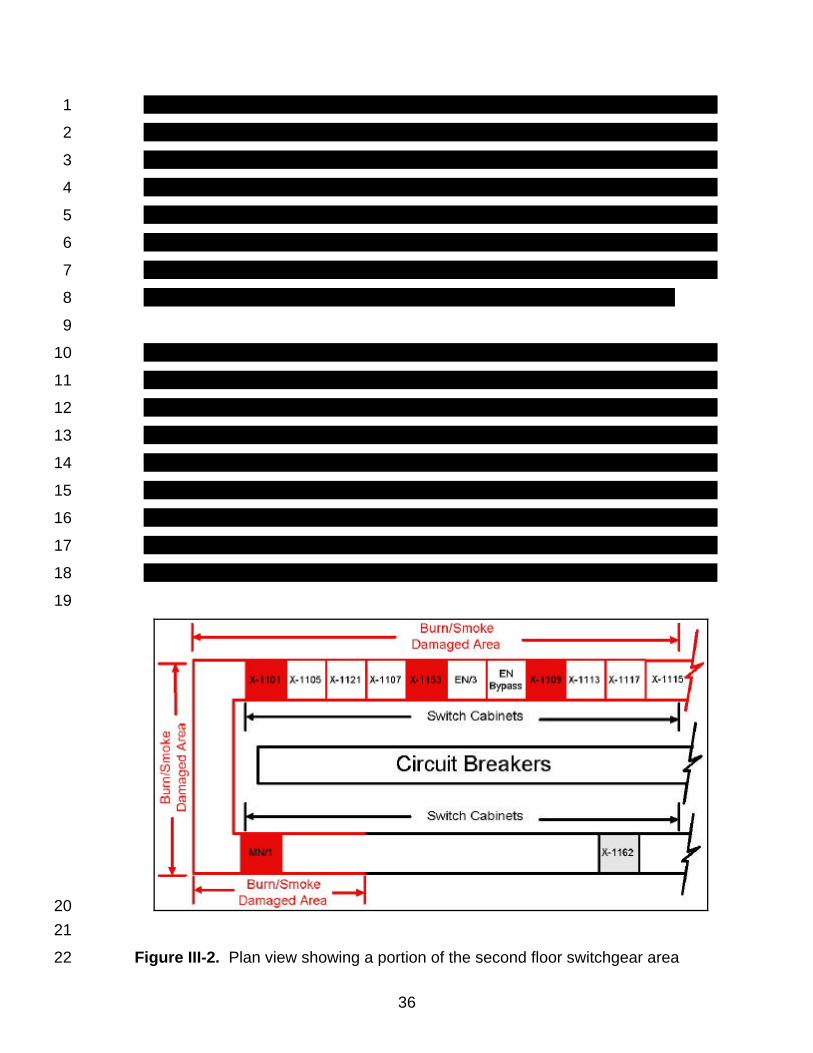
Figure III-2. Plan view showing a portion of the second floor switchgear area 22
37
1
6. Switch Cabinets and Associated Equipment 2 3
The root cause of the incident was a cable failure in a switch cabinet. The 4
cable failed explosively, which caused a bus located above it to catch on 5
fire. Over time, vertically installed cable with oil impregnated paper 6
insulation loses its insulating capability because the insulation dries out, 7
resulting in a short circuit. 8
9
Switch cubicle openings did not have barriers to contain smoke. In both 10
the 1996 and 2003 incidents, smoke flowing through cubicle openings 11
caused arcing between exposed, live electrical parts that ignited a fire. 12
13
Figure III-3 illustrates the X-1153 switch cubicle, essentially a sheet metal 14
cabinet, with the N bus directly above it. Two three-phase switches are the main 15
pieces of equipment in the cabinet. Each three-phase switch is operated as a 16
group. This is depicted with the two dashed lines in the diagram. The bottom 17
three-phase switch is normally closed, and the top three-phase switch is normally 18
open. The arrangement allows for power to be fed to the X-1153 distribution 19
cable from either Bus Section G or the N bus, thus allowing for flexibility of 20
operation. For example, if the X-1153/2 circuit breaker needs to be repaired or 21
replaced, the X-1153/3 switch is opened and the X-1153/5 switch is closed. 22
23
38
1 2
Figure III-3. The X-1153 switch cabinet with the N bus located on top 3
4
Other equipment in the switch cabinet includes a set of three cables coming from 5
the circuit breaker up through the bottom of the floor that connects to the X-6
1153/3 switch, and one paper insulated lead covered cable (PILC) exiting the 7
switch cabinet going out to the network circuit. Figure III-4 illustrates a typical 8
PILC cable. Above the X-1153/3 switch, each phase is connected to the pothead 9
with a metal bar. The outgoing network distribution cable terminates at the 10
pothead and descends vertically to the basement, where it continues out 11
horizontally to connect to the X-4 network. The PILC cable consists of three 12
copper conductors contained in a single cable with a lead sheath and a neoprene 13
jacket. Each conductor is insulated from the others by oil-impregnated paper. 14
The cable was manufactured in 1963. The failure of the PILC cable near the 15
pothead was the initiating event of the incident. 16
39
1
2 3
Figure III-4. A typical PILC cable4 4
5
Two other pieces of equipment shown in Figure III-3 are a pothead and a 6
potential transformer. A pothead is a mechanical connector that reduces 7
electrical stress at the cable termination point of the PILC cable. A potential 8
transformer is a device used to measure voltage at a particular point in a circuit. 9
10
7. Networks 11 12
PG&E had no written procedures for the loss of a network circuit. 13
Although a single network circuit failure caused a fire in 1996 and network 14
designers assumed such a condition would be immediately investigated, 15
PG&E operators did not have instructions to respond immediately to this 16
event. 17
4 Image copied from The Canadian Copper and Brass Development Association, http://www.ccbda.org/publications/pub23e/23e-Section3.html
40
1
Networks are used on the PG&E system to provide high reliability service to 2
customers. -------------------------------------------------------------------------------------------3
------------------------------------------------------------------------------------------------------------4
------------------------------------------------------------------------------------------------------------5
------------------------------------------------------------------------------------------------------------6
------------------------------------------------------------------------------------------------------------7
------------------------------------------------------------------------------------------------------------8
------------------------------------------------------------------------------------------------------------9
---------- 10
11
------------------------------------------------------------------------------------------------------------12
------------------------------------------------------------------------------------------------------------13
------------------------------------------------------------------------------------------------------------14
------------------------------------------------------------------------------------------------------------15
------------------------------------------------------------------------------------------------------------16
------------------------------------------------------------------------------------------------------------17
------------------------------------------------------------------------------------------------------------18
---------------------------------------------------------------------------------------------------- 19
20
8. Electric System Protective Equipment 21 22
a. Circuit Breakers 23 24
Circuit breakers are used to protect feeders from overloads and to protect the 25
electrical system from short circuits in the feeders. They are special switches 26
designed to interrupt the highest short circuit current they will encounter and to 27
open automatically on either overload or short circuit in the feeder. Circuit 28
breakers are also used at the termination of the 115 kV transmission lines that 29
supply the substation. In this application, they protect the transmission lines and 30
the high voltage network from short circuits inside the substation and are used as 31
switches to turn off the power to the substation in case of major trouble. The 115 32
41
kV circuit breakers operate automatically in case of a short circuit and can be 1
opened and closed manually by the high voltage operator at the SMCC. 2
3
b. Relays 4 5
The 1162 circuit breaker tripped on reverse current when the voltage on the 6
Section H bus fell almost to zero as a result of the fault in the X-1109 7
cubicle. The instantaneous units in the circuit breaker’s overcurrent relays 8
initiated the trip. Opening of the circuit breaker under these conditions is 9
undesirable because it could unnecessarily drop customer power. 10
11
A relay is used to detect overloads and short circuits and to automatically operate 12
a circuit breaker when either condition exists. There are numerous types of 13
relays. Those used with feeder circuit breakers are called overcurrent relays 14
because they detect and operate when the current in the feeder is above a set 15
value. Most overcurrent relays have an instantaneous element and a time 16
element. The instantaneous element operates (“picks up”) at a high value of 17
short circuit current without any deliberate time delay: when the pick up threshold 18
is reached, it operates in about one 1/60 of a second. The time element has a 19
pick up time which varies with the magnitude of the short circuit current or 20
overload, the higher the magnitude of the short circuit current or overload, the 21
shorter the pick up time. 22
42
c. Network Protectors 1 2
To protect networks and the feeders that supply them, network protectors are 3
used. They are similar to circuit breakers in that they will open the circuit to 4
interrupt the current in the event of a short circuit in the load. In this case, the 5
network will open the circuit on small or large magnitude current in the reverse 6
direction, that is, from the network toward the substation. Reverse current will 7
occur when there is a short circuit in the feeder or when the voltage at the 8
substation bus to which the feeder is connected falls to a low value. This 9
happened on 12/20/03 when there was a multi-phase short circuit in switch 10
cabinet X-1109, which caused the voltage on bus section H to fall close to zero. 11
Network feeder X-1162 was also connected to bus section H. When the voltage 12
fell close to zero, the network protector being fed by the X-1162 feeder operated 13
on reverse current. 14
15
9. Fire Detection and Suppression System 16 17
There were no smoke detectors at Mission substation at the time of the 18
December 20, 2003 incident despite earlier recommendations to install 19
them in certain areas. 20
21
Fire suppression equipment is adequate at Mission Substation, but it can 22
be improved in key areas consistent with recommendations in the 1996 23
CES Substations Fire Project Report. 24
25
The existing fire detection systems are intended to protect major oil-filled 26
equipment. However, they are not designed to protect the potheads, basement 27
cable spreading room or sub-basement areas. The 1996 CES Fire Project Report 28
itemizes these areas as areas to consider for further possible protection. At the 29
time of the incident, there were no smoke detectors at Mission Substation. Nor 30
were there any heat detectors in the specific vicinity of the fire. 31
32
43
On the first floor, there are individual water deluge systems in each of the rooms 1
containing the five 115/12 kV transformers, the two 12/4 kV transformers, and the 2
nine 115 kV oil circuit breakers. Each of the water deluge systems on the first 3
floor is activated by the heat detectors associated with each water spray system, 4
which consists of a dry pipe arrangement. A solenoid valve is upstream of the 5
piping. With detection of heat from a fire, the solenoid valve actuates the deluge 6
valve via a fire control panel (FCP). The open head nozzles spray water into the 7
area containing the equipment where the heat was detected. 8
9
The basement also has a wet pipe fire sprinkler system that covers the 115/12 10
kV transformer heat exchangers. This system is operated by heat as sprinkler 11
heads will fuse at 165 degrees. Heat is required at each location for the sprinkler 12
to activate. 13
14
PG&E Corporation Insurance Department, Property Loss Control Group, 15
establishes and monitors the installation, servicing, and adequacy of fire 16
protection equipment at Mission Substation. This program is based on best 17
industry practices, the requirements of the National Fire Protection Association, 18
the California Code of Regulations, and Title 19. Installation/servicing 19
requirements of fire protection equipment are addressed in the Corporate Fire 20
and Risk Control Manual. The adequacy of fire protection equipment is 21
addressed through internal and third party audits conducted to satisfy corporate 22
expectations for property loss control and to satisfy insurance carrier 23
requirements. 24
25
On June 17, 2003, an independent auditor performed an annual inspection and 26
tests of the fire alarm-heat detection and deluge systems in accordance with the 27
California Code of Regulations, and Title 19. No deficiencies were noted 28
although reference was made to a needed 5-year service for the wet pipe 29
sprinkler system in the basement. This work was scheduled for February 5, 2004. 30
31
44
10. Ventilation System 1 2
Roof fans can only be turned on manually at the fan location. The SFFD 3
needed the fans to ventilate the building and were forced to use a ladder 4
truck access the building roof to operate the fans. 5
6
The ventilation system consists of 12 fans. Two fans are on the roof, two fans 7
are located in the mezzanine area between the first and second floors, and eight 8
fans are located in the basement. 9
10
Power for the fans comes from the station service bus (house power). The 11
service bus receives power either from a source internal to Mission substation or 12
from an external source used as a backup power supply. When power is lost to 13
the substation, house power can be restored using the alternate source of power, 14
which comes from station I. 15
16
The fans are started from a motor contactor selector control box located near 17
each fan. The selector control box has three selections: start, run and off. The 18
fans must be started one at a time due to the large size of each fan. The selector 19
must be put in the start position until the motor reaches a minimum speed, at 20
which time the selector can be put in the run position. The ventilation fans can 21
be turned off at each fan location. The fans can also be turned off at a control 22
panel on the second floor, or by de-energizing the source for the second floor 23
control panel, which is the station service bus. 24
25
11. Emergency Lighting 26 27
The SFFD Rescue Squad Chief stated that there was no lighting in the 28
substation when he was there. However, there is a minimum of emergency 29
lighting powered by the station battery that automatically turns on when 30
power is lost in the substation. When the rescue squad was in the 31
45
building, the dense smoke likely diminished the intensity of the emergency 1
lighting. 2
3
When there is a loss of main power at Mission Substation, minimal lighting for 4
critical areas is automatically switched to DC battery backup power. These areas 5
include the stairwells, exits, and the control room. There is no other source of 6
emergency lighting. 7
8
46
Chapter Five: GGCC Operations 1 2
This chapter briefly discusses staffing policies for operators at GGCC and the 3
level of staffing coverage that GGCC had during the incident. It also describes 4
the SCADA screens that operators use to respond to alarms and how operators 5
respond to numerous alarms on a daily basis. 6
7
1. Staffing 8 9
On weekday nights and weekends, staffing is reduced. In the event of a 10
potentially serious event such as fire or multiple outages occurring during 11
a weekend day or on a weekday after-hours, delays in obtaining 12
appropriate on call staffing to physically assess the problem could cause 13
more severe consequences than during a typically staffed weekday. 14
15
At the time of the incident, two operators, typical for weekend operation, staffed 16
Golden Gate Control Center. The operators were monitoring the “A” desks. 17
These positions monitor the electric system, update system status, direct 18
switching, provide communication about the system, and monitor and operate 19
SCADA. There are operators at the “A” desks at all times. 20
21
On weekdays, there are also operators at the “OK” desks for San Francisco and 22
Peninsula Districts. These positions receive requests for clearances5 and write 23
the switching logs that will detail the steps to execute the clearances. The “OK” 24
desk may also assist in emergency switching. The “OK” desks are not staffed on 25
weekends or at night. 26
27
Additionally on weekdays, there may be mobile operators available to support the 28
control center operators in the field or to assist the “OK” desks. In the field, the 29
5 A clearance de-energizes a section of conductors for maintenance. A clearance can be a planned outage or service could be redirected from alternate sources to prevent an outage if possible.
47
mobile operators conduct switching for scheduled and emergency work for the 1
control center. 2
3
At the time of the incident, there were three operators present at GGCC. Two 4
operators stayed past their scheduled shift to complete switching and 5
troubleshooting that was in progress at the time their relief arrived. One of these 6
remained at GGCC and the other went to Potrero Substation to conduct 7
switching. The two relief operators were at the GGCC at the time of the initial fire 8
and X-1153 alarms. 9
10
The loss of the network feeder at the Mission substation did not require an 11
immediate physical assessment so no one dispatched additional on-call 12
personnel. PG&E management was alerted to the situation using text pages that 13
went out to designated district management. Instead, PG&E did not physically 14
investigate the X-1153 breaker trip until a second network circuit tripped and 15
customers lost power. At that time, the operator at Potrero interrupted switching 16
in progress and reported to Mission Substation. 17
18
If this incident occurred on a fully staffed weekday during daytime hours, 19
personnel from District Operations, Maintenance and Construction, or other 20
available on-duty operators would have been sent to Mission Substation 21
immediately after the initial network circuit alarms or the fire system trouble 22
alarms. 23
24
When the second network circuit and radial circuit were lost, it was only fortuitous 25
that there was an operator in the field able to report to Mission Substation that 26
late in the progression of the fire. Had the District Operator’s from the prior shift 27
not stayed beyond their scheduled hours, there would have been further delays 28
in alerting management to make the decision to call in more personnel. 29
48
Despite the delay in assessing the problem, there were no problems in obtaining 1
other operators to work overtime and assist in restoration efforts. There were no 2
operators on scheduled vacation or filling in as vacation relief on the days of the 3
incident. 4
5
2. SCADA Alarm Monitoring 6 7
PG&E operators do not have user-friendly SCADA screens and interface 8
that enable them to effectively monitor and respond to SCADA alarms and 9
conditions. 10
11
Operators viewed each SCADA alarm as a single line of text on the District 12
Operations display monitor in a “windows” like environment. New alarms 13
appeared at the bottom of the log screen and older alarms scrolled to the top. 14
Operators could scroll back on the SCADA log screen to see prior events. 15
They could also use other specific substation windows that allowed them to 16
remotely control or see the setting or condition of specific equipment. Typically, 17
other windows were open on top of the log screen, hiding most of it so that only 18
a few of the most recent bottom lines of the log screen were visible shown in 19
Figure III-5. 20
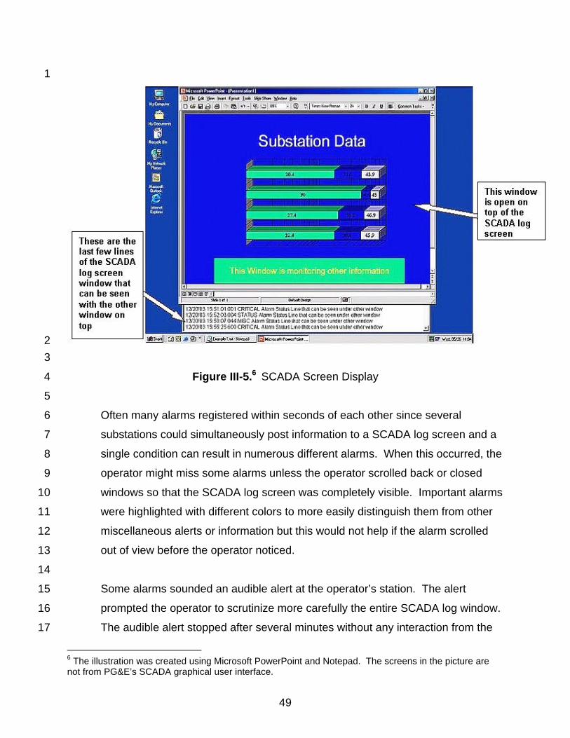
49
1
2 3
Figure III-5.6 SCADA Screen Display 4
5
Often many alarms registered within seconds of each other since several 6
substations could simultaneously post information to a SCADA log screen and a 7
single condition can result in numerous different alarms. When this occurred, the 8
operator might miss some alarms unless the operator scrolled back or closed 9
windows so that the SCADA log screen was completely visible. Important alarms 10
were highlighted with different colors to more easily distinguish them from other 11
miscellaneous alerts or information but this would not help if the alarm scrolled 12
out of view before the operator noticed. 13
14
Some alarms sounded an audible alert at the operator’s station. The alert 15
prompted the operator to scrutinize more carefully the entire SCADA log window. 16
The audible alert stopped after several minutes without any interaction from the 17
6 The illustration was created using Microsoft PowerPoint and Notepad. The screens in the picture are not from PG&E’s SCADA graphical user interface.
50
operator and had a volume control that could lower the intensity of the audible 1
alert. To silence the audible alert earlier, the operator clicked with a computer 2
mouse on an “acknowledge” button in the SCADA log window. The operator did 3
not have to acknowledge every individual alarm. The operator could also use an 4
“acknowledge all” button to silence the audible alert and to acknowledge all 5
alarms whether the operator viewed the specific alarms or not. The purpose of 6
an acknowledge button was to ensure that the operator was aware of existing 7
conditions that might require attention. 8
9
The alarms from the initial X-1153 cable fault that started the chain of events 10
(before the fire) appeared on the SCADA log screen and sounded an audible 11
alarm. The operator did not see or hear the alarms before the audible alarm 12
timed out. For unknown reasons, the operator was not at the normal desk post 13
at the exact moment when SCADA reported the alarms. The operator was not 14
aware of the fault until a customer service representative called him ten minutes 15
after the first X-1153 alarm. It was only then that the District Operator checked 16
the SCADA log and saw that the X-1153 circuit breaker was open. 17
18
On December 20, 2004, a total of 558 audible alarms registered at the GGCC, 19
including alarms resulting from the Mission Substation outage. Since all status 20
alarms were audible even though they may not indicate an emergency or special 21
notice and audible alarms eventually timed out, operators did not investigate 22
every audible alarm. 23
24
3. SCADA Alarm Response 25 26
The GGCC district operators cannot recognize, prioritize, and respond 27
effectively when a large number of SCADA alarms arrive in a short period 28
of time. This is why operators did not respond to the initial X-1153 and fire 29
subsystem audible alarms. 30
51
GGCC relied heavily on the individual knowledge and experience of 1
operators in responding to specific SCADA alarms and system conditions. 2
This contributes to inconsistent and possibly inefficient responses to 3
emergencies. 4
5
SCADA has a single nonspecific alarm for the many auxiliary bus breakers, 6
preventing an operator from determining which breaker generated the 7
alarm. 8
9
The Operating Center Manual did not include instructions on what to do when a 10
network circuit breaker opens. During interviews, operators explained that there 11
was no formal procedure or instruction covering how operators should respond to 12
specific alarms. There were many variables operators should consider when 13
assessing the importance and significance of any particular alarm. The 14
knowledge and experience of a District Operator was critical. For example, some 15
factors an operator needed to consider before pursuing a definite course of 16
action were the following: severity of alarm, type of alarm, existing outages to 17
customers, or other network conditions. When the X-1153 circuit opened, there 18
was no outage. Additionally, the operator’s assessment of the alarms found that 19
there were no other coinciding conditions that warranted immediate intervention. 20
The operator notified the field operator to investigate after completing work in 21
progress at Potrero substation. 22
23
Operating procedures for (N-1)7 or (N-2) scenarios did not exist. As became 24
apparent during the investigation, system designers and system operators did 25
not have the same understanding of how to respond to either scenario. 26
Substation engineering understood the loss of a single network feeder to require 27
immediate attention. District Operator’s understood the loss of a single network 28
feeder to require attention as soon as available personnel could investigate. 29
7 N-1 refers to a loss of one circuit in a network group. N-2 refers to a loss of two network circuits.
52
The GGCC did not immediately send an operator to investigate the open breaker 1
on the network circuit, (N-1), because it was a weekend and the only operator or 2
switchman available in the field was busy at another substation. The District 3
Operator also paged key personnel to inform them that the X-1153 circuit was 4
out, a major downtown customer reported power problems, and there was no 5
outage on the network containing X-1153. The D.O. then notified an 6
underground electrical foreman that the cable might need to be replaced before 7
other scheduled work on the next workday. District management that received 8
the page out did not direct additional personnel to assist the District Operator. 9
The switchman in the field was not directed to immediately investigate the alarms 10
at Mission substation until SCADA reported the loss of a second network circuit 11
and a radial circuit dropped power to 3112 customers. 12
13
During interviews, the District Operator’s emphasized that many system 14
conditions affect the specific action one would take in response to a circuit 15
breaker operating. Knowledge and experience of a District Operator rather than 16
established procedures defined the response. 17
18
53
Chapter Six: Fire Coordination 1 2
In CPUC interviews with the SFFD Battalion Division Chief and Head of the 3
Rescue Squad, he described several coordination problems that resulted in poor 4
fire coordination at the scene of the incident: 5
6
1. Incident Command System (ICS) 7 8
It was not clear whom the PG&E Lead Supervisor or Person-In-Charge (PIC) 9
was to coordinate with the SFFD Incident Commander. 10
PG&E did not have any written procedures that define this role when PG&E 11
personnel respond to trouble at an unattended substation. 12
PG&E and SFFD had no prior agreements about how a proposed Incident 13
Command System (ICS) would operate during a substation fire emergency. 14
15
According to the SFFD Battalion Division Chief, PG&E lacked a single reliable 16
contact or person-in-charge (PIC) at the scene to supply critical information and 17
knowledge necessary for the SFFD to implement effective emergency response 18
activities. Necessary activities typically include the following: confirm the 19
number of people inside, determine the extent of possible injuries, confirm what 20
is known about the event and what to look for; identify potential hazards and 21
flammables, apply lessons learned from previous fires (e.g. 1996 Fire); and 22
review a floor plan and physical arrangements (ventilation switches, shut off and 23
back up power). Emergency response is delayed and less effective in the 24
absence of this information and knowledge. 25
26
During the incident, the Battalion Division Chief threatened to “flood the building 27
top to bottom” if he did not get better coordination with a lead PG&E contact. He 28
said that he had the impression that the person-in- charge kept changing. 29
According to PG&E, an Electric Transmission Underground Supervisor finally 30
took charge because of his knowledge and expertise in underground and indoor 31
equipment, and his direct responsibility for substation equipment in San 32
54
Francisco. The SFFD did not know what PG&E Supervisor was in charge until 1
the SFFD second visit—approximately four hours after the initial fire alarm. Once 2
the PG&E supervisor took charge and identified himself to the SFFD, he was 3
able to guide a Junior Battalion Chief over the radio to the rooftop exhaust fan 4
power switch that was not easily accessible. 5
6
According to the SFFD, the Incident Command System is important since it 7
provides a systematic development of a complete, functional Command 8
organization designed to allow for single or multi-agency use that increases the 9
effectiveness of Command and firefighter systems.8 Major functions include 10
planning, logistics, finance/administration, safety, and information for structural 11
fire incidents. Roles and functions become more elaborate as the emergency 12
increases in scope and intensity. 13
14
2. Emergency Response Planning 15 16
PG&E and SFFD personnel were not guided by an agreed upon joint 17
emergency response plan as recommended in the April 1996 CES-18
Substations Fire Project Report. This plan would provide information 19
critical to firefighters during an emergency, such as maps, a list of hazards, 20
emergency numbers, and locations of ventilation switches. 21
22
At the time of the incident, PG&E did not have a written Mission Substation 23
Emergency Response Plan or PG&E Facility Environmental Emergency Plan 24
(FEEP) for Mission Substation as recommended in the April 6, 1996 CES-25
Substations Fire Project Report. This plan provides a detailed map of each floor 26
indicating where high voltage breakers, banks and disconnects are located as 27
well as where hazardous material such as lead acid batteries are located. It 28
identifies various hazardous materials and high voltage equipment within the 29
substation. It identifies combustibles such as insulating oil in the station 30
transformers and lists fire suppression equipment that may be needed. It 31
8 San Francisco Fire Department “ICS Fire Department Operations”
55
explains the preferred extinguishing agent to fight fires. At the time of the 1
incident, firefighters’ access to these written materials would have allowed them 2
to conduct a more thorough inspection and more quickly respond to the 3
emergency. 4
5
From interviews with PG&E, we learned that PG&E attempted to hand carry a 6
draft Emergency Response Plan to the SFFD following the 1996 fire. However, 7
efforts to coordinate joint meetings, confirm plans, and conduct related necessary 8
training failed. When we asked the SFFD personnel about the issue, they said 9
that they were unaware of the effort. They believed that PG&E’s efforts did not 10
receive priority because the concern was not escalated high enough in the SFFD 11
organization. 12
13
According to interviews, the SFFD Incident Commander and Head of the Rescue 14
Squad did not know there was a floor plan stored in an envelope on the inside of 15
the substation door. Nor did they receive specific details pertaining to a similar 16
fire that took place in 1996. If the firefighters had had access to a map of the 17
substation, it is likely that they would have been more successful in using the 18
infrared camera to detect hot spots and avoid high voltage areas. Further, if the 19
firefighters had known about details relating to the 1996 fire, they could have 20
been more effective in their search for the origin of the fire, which was in the 21
same vicinity as the 1996 fire. The delay in locating the fire resulted in more 22
extensive damage and contamination in the substation, and prolonged customer 23
outages. 24
25
In terms of fire fighting equipment, the firefighters were initially using air chisels to 26
cut open the bus duct to fight the fire. Other firefighters who were knowledgeable 27
about the 1996 Fire recommended using socket wrenches to remove the bolts 28
holding the duct panels together as they had done in 1996. The Incident 29
Commander believed that they could have fought the fire better and faster if they 30
had known this before and if they had more wrenches. 31
32
56
During the incident there did not exist an agreed upon policy regarding what 1
extinguishing agent to use to fight the fire. PG&E asked the SFFD not to use 2
water and to use dry chemicals or CO2 exclusively. However, it was necessary 3
to eventually use water since other approaches were not practical or effective. 4
5
Between the 1996 and 2003 Mission Substation fires, PG&E and the SFFD 6
have had little communication on common issues and concerns. This 7
resulted in ineffective substation fire response. 8
9
Since the 2003 fire, PG&E and SFFD have conducted several meetings in the 10
spring and summer of 2004 to discuss the fire coordination issues. Meetings 11
included a review of facility checklists, review of emergency response plans, 12
substation and plant orientations, terrorist type drills, and training bulletins and 13
updates. PG&E and SFFD also used these meetings as forums to brainstorm 14
other potential fire coordination activities. Topics of discussion included 15
annunciation of alarms and monitoring of fire detection system signals by a City 16
Central Alarm Station, use of distinctive clothing to identify PG&E person-in-17
charge, and potential use of SCBA (Self Contained Breathing Units) by PG&E 18
personnel. They have also discussed having real-time monitoring of closed 19
circuit cameras inside Mission Substation. 20
21
PG&E also planned to initiate a fire department training program that will include 22
“train the trainer” sessions to familiarize the SFFD with PG&E work practices, 23
equipment and facilities. PG&E reviewed SFFD training materials and fire 24
protection equipment. 25
26
57
3. Smoke Filled Substation Task Force 1 2
According to a 2003 bulletin, PG&E employees are not allowed to enter 3
smoke-filled substations. Prior to the December 20, 2003 event, PG&E did 4
not initiate discussions with the SFFD about specific details in the bulletin. 5
6
In response to an incident at Potrero Substation in April 2003, PG&E created a 7
“Smoke Filled Substation Task Force” to develop guidelines regarding PG&E 8
personnel entering smoke-filled substations. According to Safety, Health and 9
Claims, previous guidelines were “vague” and “open to interpretation”. 10
11
As a result of the task force review, PG&E developed an interim bulletin entitled 12
“Entry into a Substation/Building that is on Fire or Suspected on Fire” in the 13
summer of 2003. Its purpose was to “bridge identified gaps regarding employees 14
entering a substation building where smoke or fire may be present, and to 15
provide guidance to those employees until a formal process can be developed.” 16
17
Although supervisors communicated this bulletin to employees in an appropriate 18
tailboard format, it is not known when PG&E will incorporate the contents of the 19
bulletin into formal policy. At the time of the posting of this bulletin, apparently 20
PG&E did not formally meet with the SFFD to discuss the contents or related 21
issues. 22
23
58
Chapter Seven: Restoration 1 2
PG&E has no written restoration guidelines for Mission Substation and 3
other substations. Reporting discrepancies existed regarding the total 4
number of customers affected during the course of the incident. 5
6
PG&E’s restoration policy is to restore the greatest number of customers in the 7
least amount of time, balanced by a requirement to restore service to small 8
numbers of customers who have been out of power for a long period of time. In 9
restoring service following the fire at the Mission Substation, PG&E personnel 10
maintain that they followed a strategy of restoring as many customers as 11
possible in the least amount of time. 12
13
As a result of the incident, PG&E believes that it needs to review its policy 14
regarding what components of its distribution system including which radial, 15
network, and tie-cable systems should be energized and in what order. PG&E 16
energized the tie-cable circuits from the Mission Substation at approximately 2 17
a.m. This was appropriate since none of the equipment on the third-floor was 18
damaged by fire or smoke and was available for service. After the tie cables 19
were restored, there was an issue about whether or not to restore the network 20
circuits or radial circuits next. PG&E decided to restore the radial circuits since 21
more customers were involved. In hindsight, PG&E believes that this was the 22
best approach. 23
24
However, PG&E believes that written guidelines are necessary to help personnel 25
make these decisions when multiple distribution systems (e.g. radial, tie-cable, 26
network) are involved. According to PG&E, the guidelines should note the 27
following factors: timing of the outage (week-day vs. week-end, business hours 28
vs. non-business hours), the nature of the damage (if any), and other factors 29
discussed in the Company’s Electric Emergency Operations Plan such as the 30
presence of hospitals, fire departments, etc. 31
59
Chapter Eight: Outage Communication 1 2
Estimated Time of Recovery (ETOR) was underestimated during the 3
incident resulting in overoptimistic feedback to customers about when 4
their service would be restored. 5
6
During the incident, PG&E underestimated the time it would take to establish 7
clearances, and clean and restore equipment while customers were out of power. 8
Equipment that was either damaged or rendered inoperable due to soot or other 9
debris from the fire, required extensive hand cleaning and follow-up inspections. 10
A realistic restoration plan needs to take into account the extent of damaged 11
equipment, equipment that needs to be cleaned, the number of switchgear 12
cabinets that needed to be cleared for cleaning, available operational personnel 13
that can work within switchgear cabinets, and the circuits required to energize 14
each network group. Without this knowledge, PG&E provided an overly 15
optimistic estimated time of restoration (ETOR) to customers. 16
17
During the incident, the OIS (Outage Information System) provided questionable 18
information regarding the number of customers out of power. Since the incident, 19
PG&E performed a manual workaround to correct the problem. PG&E plans to 20
perform permanent programming changes in the OIS system in the future. 21
22
60
Chapter Nine: 1996 Mission Substation Fire 1 2
1. Description of the Event 3 4
As described in PG&E’s report on the 1996 fire9, at 12:34 p.m. on November 26, 5
a 12 kV cable splice short circuited and caused an X-1117 circuit breaker to 6
open. The breaker operation was reported by SCADA to the GGCC. The splice 7
was located approximately six feet from the first floor ceiling, just below the 8
opening in the floor at the bottom of the X-1117 switch cabinet. 9
10
The short circuit in the splice burned the cable insulation and produced much 11
smoke, which rose through the floor opening into the switch cabinet. Once the 12
cabinet filled with smoke, events occurred just as in the 2003 fire. Smoke 13
caused contamination of the air and reduced the electrical resistance between 14
phases of switch components. The reduced resistance resulted in a flashover 15
between phases of the bus bars connecting the overhead N bus to the switch, 16
causing insulation on the N bus to ignite. The short circuit on the N bus caused 17
the bus breaker to open at 0:55 a.m. (also reported by SCADA). 18
19
Around 1:00 a.m. on November 27, a PG&E employee on night shift stopped at 20
Mission substation to use the restroom. Before entering, he noticed smoke 21
coming from the building. After leaving the restroom he saw smoke, heard 22
alarms and saw cables on fire after investigating further. He went back to his 23
truck and called the Golden Gate District Operator at 01:05 a.m. He then 24
returned to the building and went up to the second floor switch room because he 25
knew that was the path of the burning cable. The fire department and his 26
supervisor soon joined him. The supervisor directed efforts to protect the 27
equipment and provided fire fighters access to the switch cabinets. Sometime 28
after 2:00 a.m., the fire department finished putting out the fire, which destroyed 29
the X-1117 cabinet and a significant portion of the N bus as well as lightly 30
damaging adjacent switch cabinets. Since the fire caused a short time service 31
9 Mission Substation Circuit X-1117 Root Cause Analysis, 12/5/1996
61
interruption only to customers supplied through the X-1117 switch, the outage did 1
not meet the reporting requirements of the CPUC so PG&E did not report the 2
incident. 3
4
2. 1996 Fire Root Cause Analysis 5 6
PG&E’s 1996 Root Cause Analysis (see Appendix B) listed three action items to 7
minimize future fire damage that were not implemented: 8
9
1. Initiate a fire barrier penetration sealing program to seal openings, 10
2. Review procedures for quickly responding to abnormal conditions such as 11
breakers operations to promptly identify potential problems, 12
3. Evaluate a cost effective method of smoke detection throughout the 13
substation. A method of remotely monitoring alarms would also be 14
reviewed. 15
16
The Root Cause Analysis also cited previous Insurance Division Property Loss 17
Prevention Reports that make the same recommendations. The second and 18
third action items, quick response and smoke detection, directly apply to the 19
2003 fire. In 1996, the Insurance Department realized that GGCC operators had 20
no way of knowing through SCADA that a fire was burning in the substation. If 21
the employee had not stopped at the substation on the night of the fire by chance 22
only, the fire would have continued until more circuits were lost, as occurred in 23
the 2003 fire. The Insurance Department stated that since the substation was 24
unattended, at least one of the two recommendations would need to be 25
implemented to prevent an undetectable fire from progressing. 26
62
3. Similarities to the 12/20/03 Event 1 2
Similar to the December 2003 fire, the overhead N bus burned and remote 3
monitoring did not detect the fire. X-1117 is a network feeder so no customers 4
lost power and no one was dispatched to the substation to investigate, although 5
SCADA reported both the X-1117 circuit breaker and an EN circuit breaker had 6
opened. Even though the initial fault differed from the 2003 fire, the immediate 7
resulting events and response were virtually identical: 8
9
1. The incident occurred during reduced staffing hours. 10
2. SCADA reported a breaker opening on a network circuit and 11
later on an auxiliary bus. 12
3. The failed cable splice produced smoke contamination that 13
resulted in arcing in the N bus that ignited the bus insulation. 14
4. SCADA did not detect or report a fire burning in the unmanned 15
substation. 16
5. PG&E did not immediately investigate the fault because it was 17
only one circuit in a network (N-1). 18
6. The fire did not self extinguish. 19
20
It was not until the investigation of the 2003 fire that PG&E’s fire expert 21
recognized the 1996 fire did not self extinguish and the significance of this 22
finding. It was commonly believed that fires involving electrical equipment 23
typically self-extinguish because the fire consumes the relatively limited 24
combustible materials. The 1996 Root Cause Analysis reported that the fire had 25
to be extinguished by the SFFD and that a continuous, smoldering fire was 26
unusual for a cable splice. The analysis did not specify that the smoldering fire 27
was on the N bus and not at the cable splice. 28
63
PG&E did not document the relevance of the 1996 fire not self-extinguishing in 1
the Root Cause Analysis. PG&E did not acknowledge the flammability of the 2
insulation on auxiliary buses. Nor did it realize that the fault on the N bus that 3
ignited the insulation occurred because the bus was normally energized. 4
5
The similarities between the 1996 and 2003 fire are important because they 6
demonstrate that PG&E should have anticipated and been prepared for the 2003 7
fire. The 1996 fire showed PG&E that a single network circuit fault could result in 8
a fire. It demonstrated the auxiliary bus insulation was made of flammable 9
material that could be ignited by a short circuit and sustain a fire. It also showed 10
that SCADA monitoring would not detect an active fire in the switch cabinets and 11
N bus. 12
64
Chapter Ten: Management Overview Process 1 2
The following section is a description of the processes used to develop, 3
implement, and track findings and/or recommendations pertaining to the following 4
analyses: 1) 1996 Fire Root Cause Analysis; 2) 1996 CES-Substation Fire 5
Project; and 3) Insurance Department Property Loss Prevention Reports. This 6
latter item will be discussed in the context of Item 2) above. All of these analyses 7
pertain to recommendations in the areas of fire prevention, fire detection and 8
monitoring, and fire suppression. 9
10
The responsible owner of these recommendations is primarily Substation Asset 11
Management. Standalone fire protection projects are prioritized and included in 12
the annual workload plan with other projects. Authorization of expenditures for 13
substations coincides with the delegation of authority tables that are based on 14
the level of authorization required. For example, the Substation Asset Manager 15
can authorize $300,000 in expenditures and the Substation Engineering Director 16
can authorize $500,000. 17
18
1. 1996 Fire Root Cause Analysis 19 20
Had PG&E implemented its 1996 investigation recommendations, CPSD 21
believes the cable failure on December 20, 2003 would not have resulted in 22
an outage to more than 100,000 customers throughout San Francisco. 23
24
The Substation Asset Management Group prioritized the recommendations of the 25
1996 Root Cause Analysis and the recommendations of the Property Loss 26
Prevention Reports. Criteria to prioritize the work consisted of the following: 27
28
• Life safety and oil related hazards; 29
• Continuity of operations; and 30
• Asset preservation. 31
65
1
Based on this prioritization, two recommendations including fire detection and 2
sealing openings between floors were classified as continuity of operations—a 3
lower priority than life safety and oil related hazards. The third recommendation, 4
covering quicker response to SCADA alarms was classified as a lower priority as 5
well. 6
7
Following the incident there was no mechanism in place to track the 8
recommendations made in the 1996 Root Cause Analysis. According to defined 9
areas of responsibility, the Substation Asset Management Group was 10
responsible for the first two recommendations including fire penetration seals and 11
smoke detectors and Division Operations was responsible for the third 12
recommendation or immediate dispatch of personnel for alarms. The Asset 13
Management Group forwarded the 1996 Fire recommendations to the San 14
Francisco Division Manager, who was responsible for division operations. 15
According to PG&E, a recent search for the transmittal letter was unsuccessful. 16
17
At a subsequent PG&E meeting, the head of Substation Management agreed to 18
evaluate smoke detectors, and the Division Manager agreed to check with 19
operations regarding an immediate dispatch of personnel for alarms. Substation 20
Asset Management claimed that an informal assessment of the substation 21
revealed that they could not reasonably install a fire detection system within fire 22
code specifications. Although San Francisco City Code does not require smoke 23
detection for the building, if it were installed, it would have to comply with NFPA 24
72, the National Fire Protection Association Fire Alarm Code. 25
26
PG&E said that they did not install smoke detection on the first floor ceiling since 27
it has numerous beams and recesses that would require many sensors. 28
Substation Asset Management and the Insurance Department claimed that the 29
cost of installing sensors and connecting them to SCADA would be prohibitive 30
until more affordable technology was available. A cost-benefit study of smoke 31
66
detectors was not done and there was no formal follow up or communication 1
between the Substation and Division Operations groups on this subject. 2
3
According to PG&E, there is no supporting documentation to track the 4
recommendations made in the root cause report. Similarly, there is no 5
supporting documentation that a quarterly or annual review of this event was 6
performed in compliance with reporting guidelines in effect at that time. 7
8
2. 1996 CES-Substation Fire Project Report 9 10
At the time of the 1996 fire, PG&E did not take action to improve fire 11
detection in indoor substations that was recommended in the report. 12
13
The April 1996, CES Substations Fire Project Report completed by the PG&E 14
Insurance Division (prior to the December 1996 Fire) identified fire hazards 15
associated with indoor substations and related substations. 16
17
Following are some examples: 18
1. Toxic Smoke: While cable insulation fires do not provide much 19
heat, they typically generate a lot of smoke. Visibility is a major 20
problem in fire-fighting activities and the products of 21
combustion can be toxic depending on the cable insulation 22
material. According to the report this poses a health threat to 23
exposed individuals. 24
2. Highly Combustible Nature of Cable Fires: Cable insulation 25
fires can easily promote spreading of fires from one area to 26
another. Cable fires often spread to other areas not affected by 27
the specific cable. Shorts in one cable routed with other cables 28
often result in fire and can damage other cable. These fires are 29
typically difficult to extinguish and may, in fact, re-ignite. 30
67
3. Concerns Related to Switchgear Equipment: Non-oil filled 1
circuit breakers that reside in enclosed metal housings do not 2
present the same hazards as oil filled ones, but they do contain 3
combustible insulation. Due to a malfunction, an arc can occur. 4
If this isn’t detected early, a fire could result. 5
6
The Insurance Department initiated annual surveys to review the facility fire 7
prevention program components and comment on the adequacy of fire 8
equipment inspections and maintenance. Since the 1996 Fire, the Insurance 9
Department completed surveys in 1997, 1998, 2000, and 2002. The 2000 and 10
2002 reports identified issues in the April 1996 CES-Substations Fire Project 11
Report that were not yet resolved. This translates to a delay of approximately 12
four to six years. Issues included the following: 13
• Provide an automatic detection system in the Control Room; 14
• Extend sprinkler protection to the oil filled potheads located in the 15
same compartments as Oil Circuit Breakers (OCB’s); 16
• Verify adequacy of the existing ventilation system for the Battery 17
Room, with respect of the requirements of Article 64 of the Uniform 18
Fire Code; and 19
• Install exterior bells for local annunciation of a fire, or verify 20
acceptability of the existing condition with the local fire department. 21
22
In interviews with PG&E, a Principal Loss Control Engineer from the Insurance 23
Department pointed out that the Department’s role was an advisory one and that 24
the authority to implement Insurance Department repeated recommendations 25
rested with Substation Asset Management and Division Operations. The 26
Principal Loss Control Engineer explained that they did not seriously consider 27
automatic fire detection suppression recommendations since he was under the 28
general impression that substation electrical fires typically “self-extinguish” and 29
therefore do not require extensive firefighting intervention. During some follow 30
up interviews with the PG&E Investigation Team, PG&E indicated that personnel 31
68
were not fully aware of the fallacy of this thinking and asked to retract statements 1
that indicated otherwise. (Also, refer to Chapter Nine “1996 Mission Substation 2
Fire”, Section 3. “Similarities to the 12/20/03 Event”.) 3
4
3. Operations Standard S1465 “Event Investigation 5 Procedures” 6 7
PG&E has a slow and cumbersome process to review operating standards 8
relating to incident investigation procedures. 9
10
PG&E Utility Operations (UO) develops operations standards to ensure that all 11
aspects of its operations are conducted in a safe and consistent manner. In 12
addition to providing content, these standards contain information pertaining to 13
issuing departments, utility operations sponsors, effective dates, and review 14
dates. 15
16
The PG&E Utility Operations Standard S1465 “Event Investigation Procedures 17
for Electric Utility Operations” effective 01/01 provides for event investigation 18
procedures, reporting requirements, and implementation of recommendations 19
associated with an event. Electric Transmission and Distribution (T&D) 20
Engineering, Electric Control Center Operations (ECCO), Engineering and 21
Planning (E&P), and Operations Maintenance and Construction (OM&C) are 22
sponsors of this standard. 23
24
The required PG&E review date for S1465 is currently 1/03 but apparently PG&E 25
did not begin this activity until 9/03. Changes are numerous and significant, but 26
as of April 2004, it has not yet been reviewed or approved by PG&E 27
management. PG&E does not know when the final version will be reviewed or 28
approved. 29
30
A partial list of root cause report requirements include required communication to 31
provide ease of preparation, consistency and quality of information, and 32
69
management overview to ensure that reports are prepared in a timely manner, of 1
consistent quality, and that action items are identified and implemented by 2
responsible individuals. However, the 1996 version of this standard (E-TS-3
GOO8 effective August 1996) did not specify an adequate process for 4
management to monitor remedial actions based on event report 5
recommendations. 6
7
4. Technology Review 8 9
PG&E has no systematic procedure to review and adopt new technology 10
that can improve safety and reliability. Examples of technology related to 11
this incident include barrier seal material and laser beam smoke detector 12
technology for indoor substations. 13
14
The 1996 Fire Root Cause Analysis recommended a cost-benefit analysis of the 15
potential installation of smoke detectors with remote monitoring suitable for 16
indoor substations. Without the benefit of performing this analysis, the head of 17
Substation Management said that the only option available was the standard 18
commercial detectors that would have to be installed at tremendous cost and 19
involve complex wiring, spacing and physical arrangement, and remote 20
monitoring (Ref: NFPA 72). For this reason, PG&E decided to not implement this 21
recommendation. (Refer to Chapter Ten. “Management Review Process”.) 22
23
Following the 1996 Fire, PG&E was not aware of, nor did they research laser 24
beam technology that is highly effective at less cost. The CPUC Investigation 25
Team recently consulted various laser beam smoke detector vendors and found 26
that this technology has been available for indoor electric substation for about 20 27
years. The beam technology currently used in several PG&E indoor substations 28
in the East Bay Area was available as early as March 1994. 29
30
Similarly, 1996 Fire Root Cause Analysis recommended that a fire barrier 31
penetration-sealing program to seal openings be implemented. In interviews, 32
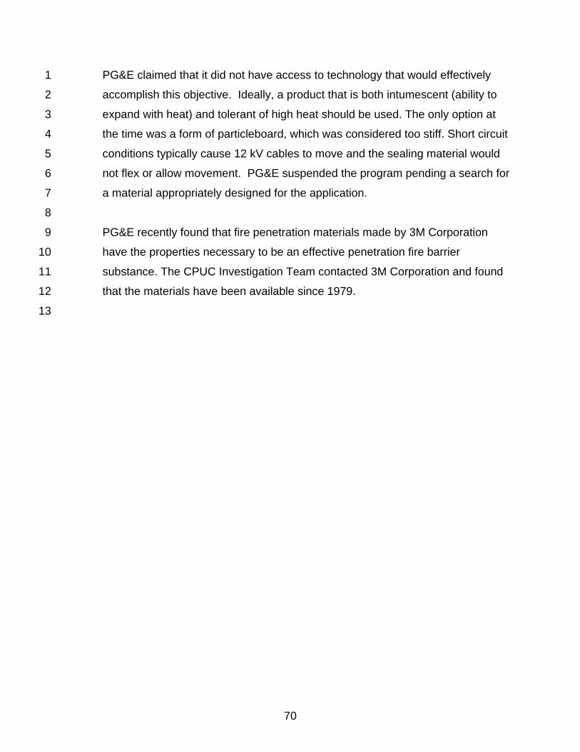
70
PG&E claimed that it did not have access to technology that would effectively 1
accomplish this objective. Ideally, a product that is both intumescent (ability to 2
expand with heat) and tolerant of high heat should be used. The only option at 3
the time was a form of particleboard, which was considered too stiff. Short circuit 4
conditions typically cause 12 kV cables to move and the sealing material would 5
not flex or allow movement. PG&E suspended the program pending a search for 6
a material appropriately designed for the application. 7
8
PG&E recently found that fire penetration materials made by 3M Corporation 9
have the properties necessary to be an effective penetration fire barrier 10
substance. The CPUC Investigation Team contacted 3M Corporation and found 11
that the materials have been available since 1979. 12
13
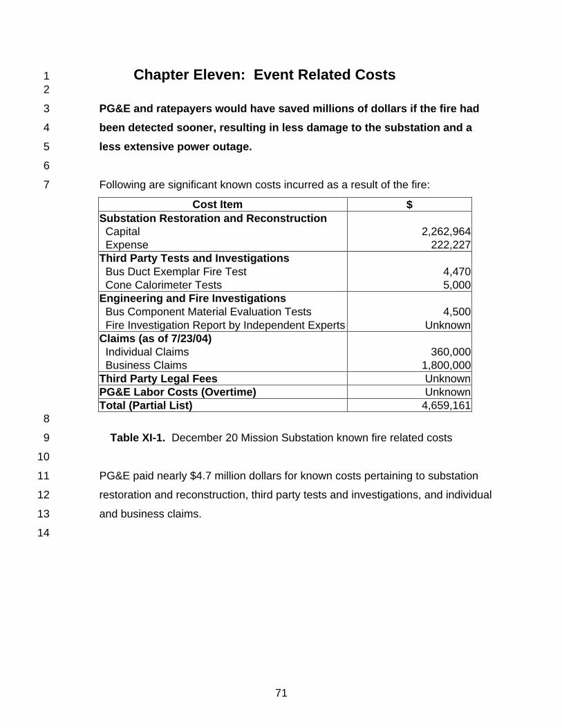
71
Chapter Eleven: Event Related Costs 1 2
PG&E and ratepayers would have saved millions of dollars if the fire had 3
been detected sooner, resulting in less damage to the substation and a 4
less extensive power outage. 5
6
Following are significant known costs incurred as a result of the fire: 7
Cost Item $ Substation Restoration and Reconstruction Capital 2,262,964 Expense 222,227 Third Party Tests and Investigations Bus Duct Exemplar Fire Test 4,470 Cone Calorimeter Tests 5,000 Engineering and Fire Investigations Bus Component Material Evaluation Tests 4,500 Fire Investigation Report by Independent Experts Unknown Claims (as of 7/23/04) Individual Claims 360,000 Business Claims 1,800,000 Third Party Legal Fees Unknown PG&E Labor Costs (Overtime) Unknown Total (Partial List) 4,659,161 8
Table XI-1. December 20 Mission Substation known fire related costs 9
10
PG&E paid nearly $4.7 million dollars for known costs pertaining to substation 11
restoration and reconstruction, third party tests and investigations, and individual 12
and business claims. 13
14
72
Chapter Twelve: Detailed Description of the Event 1 2
For references to specific pieces of equipment, refer to Figure III-2, single line 3
diagram of the Mission Substation. 4
5
1. Cable Failure 6 7
The blackout of much of downtown San Francisco, which happened on 8
December 20, 2003, started with a short circuit in the X-1153 cable where it 9
enters the metal clad cubicle which houses switches 1153/3 and 1153/5. The 10
cable, installed more than 40 years ago, was, and for most of its length still is, 11
composed of a copper conductor with oil-impregnated paper insulation and a 12
lead sheath. It rises vertically from below street level to the second floor of the 13
substation where it enters the switch cubicle. In the course of time, the oil in the 14
insulation under the force of gravity migrated down the cable, leaving relatively 15
dry paper of significantly diminished insulating value at the top. The reduced 16
insulation caused the short circuit in the cable. The resulting damage is shown in 17
Figure XII-1. 18
19
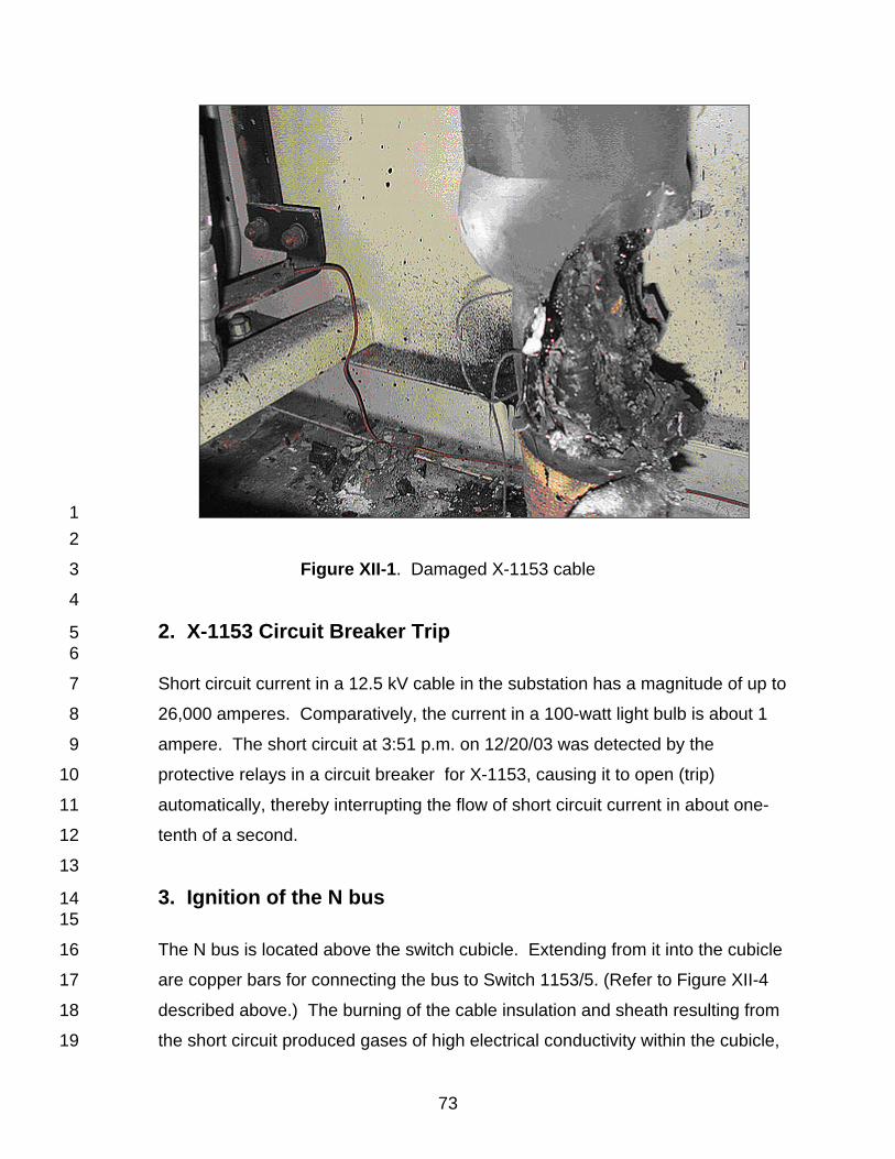
73
1 2
Figure XII-1. Damaged X-1153 cable 3
4
2. X-1153 Circuit Breaker Trip 5 6
Short circuit current in a 12.5 kV cable in the substation has a magnitude of up to 7
26,000 amperes. Comparatively, the current in a 100-watt light bulb is about 1 8
ampere. The short circuit at 3:51 p.m. on 12/20/03 was detected by the 9
protective relays in a circuit breaker for X-1153, causing it to open (trip) 10
automatically, thereby interrupting the flow of short circuit current in about one-11
tenth of a second. 12
13
3. Ignition of the N bus 14 15
The N bus is located above the switch cubicle. Extending from it into the cubicle 16
are copper bars for connecting the bus to Switch 1153/5. (Refer to Figure XII-4 17
described above.) The burning of the cable insulation and sheath resulting from 18
the short circuit produced gases of high electrical conductivity within the cubicle, 19
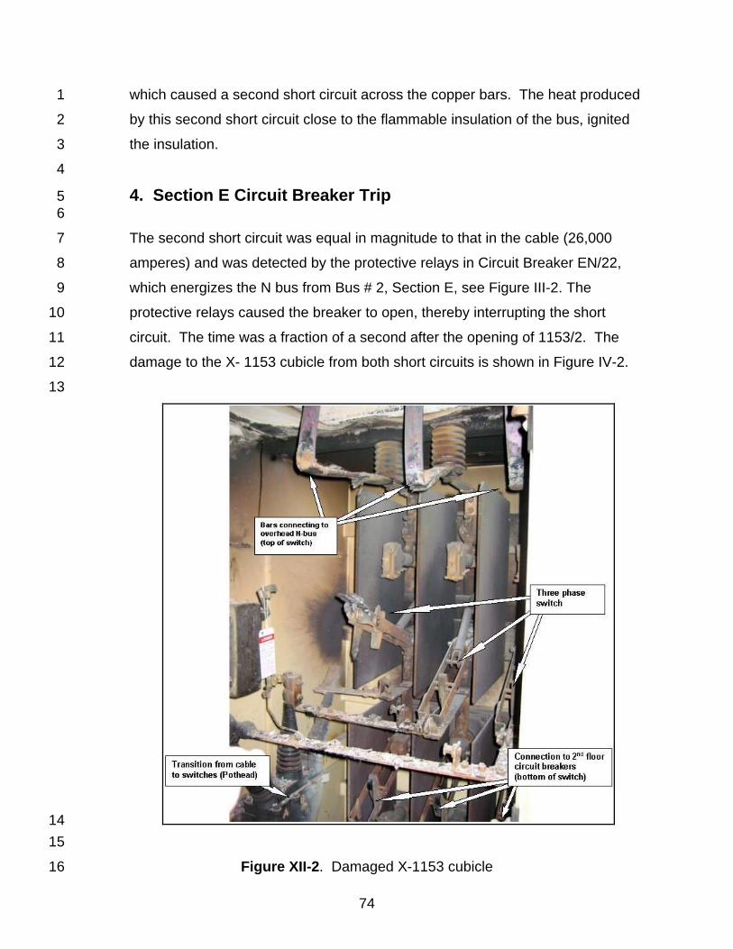
74
which caused a second short circuit across the copper bars. The heat produced 1
by this second short circuit close to the flammable insulation of the bus, ignited 2
the insulation. 3
4
4. Section E Circuit Breaker Trip 5 6
The second short circuit was equal in magnitude to that in the cable (26,000 7
amperes) and was detected by the protective relays in Circuit Breaker EN/22, 8
which energizes the N bus from Bus # 2, Section E, see Figure III-2. The 9
protective relays caused the breaker to open, thereby interrupting the short 10
circuit. The time was a fraction of a second after the opening of 1153/2. The 11
damage to the X- 1153 cubicle from both short circuits is shown in Figure IV-2. 12
13
14 15
Figure XII-2. Damaged X-1153 cubicle 16
75
1
5. Initial Alarms 2 3
The Mission Substation is unattended and its primary functions are controlled 4
from the GGCC in Daly City by means of SCADA. (Refer to Chapter Four 5
“Mission Substation Facilities”, Section 2. “SCADA”.) SCADA reported the 6
automatic tripping of X-1153 circuit breaker at the time of its occurrence by a 7
message on the GGCC operator’s computer monitor. The automatic tripping of 8
bus breaker was announced as the trip of a circuit breaker connected to the E 9
Section bus, but the alarm notice did not specify which of the 28 circuit breakers 10
connected to that bus section. At the same time, the operation of the X-1153 11
protective relays caused low voltage conditions on Buses 1 and 2 resulting in an 12
alarm and further alarms of unspecified cause were received from 4 of the 5 13
transformers and the water deluge system. All told, at 3:51 p.m., the GGCC 14
received 11 alarms from Mission Substation within 1 second. The short circuits 15
were the direct cause of the circuit breaker trip and relay operation alarms, and it 16
is now known, although at the time the operator had no way of telling, that the 17
transformer and water deluge system alarms were caused by the voltage dip 18
resulting from the short circuits. 19
20
6. Initial Operator Response 21 22
During the week, PG&E has mobile crews of maintenance personnel available to 23
respond to substation trouble, but not on the weekends. On weekends personnel 24
from the GGCC are dispatched to investigate trouble. However, the X-1153 25
circuit is only one of six circuits supplying the X4 network, which can meet peak 26
load with only five supply circuits in operation. It was accepted procedure at the 27
GGCC not to respond immediately to circuit breaker trips, which did not cause 28
loss of load. Likewise, because there had been no report of a power outage, 29
investigation of the trip of the circuit breaker connected to Bus Section E could be 30
postponed, as could the source of the other alarms. The breaker trip alarm was 31
76
transmitted by the operator’s assistant to the operations supervisor, who also did 1
not consider the event to be of sufficient importance for immediate response. 2
3
7. Power Problem Reported by Large Commercial 4 Customer 5 6
The controls of large motors, such as the drives for air conditioning compressors, 7
are known as motor starters. Their electrical contacts are closed by an 8
electromagnet. When there is a significant dip in the supply voltage, current in 9
the electromagnet drops and the motor starter opens, de-energizing the motor to 10
prevent damage. As mentioned in Section 5 above, “Initial Alarms”, a large 11
magnitude short circuit will drop the voltage at the source bus to almost zero. At 12
4:02 p.m., a large commercial customer reported that its air conditioning chillers 13
had shut down. On the assumption that the shutdown was due to a problem with 14
supply voltage, the customer reported the incident to PG&E. We now believe the 15
starter on the chiller motors opened due to the voltage dip caused by the X-1153 16
short circuit. 17
18
8. Propagation of Fire Along the N Bus 19 20
We believe that the short circuit across the bars connecting to the N Bus in the X-21
1153 switch cubicle started a fire in the N Bus above the cubicle and that the 22
electrically conductive combustion products in the form of ionized gases 23
propagated along the bus in both the Easterly and Northerly directions to the 24
junction with Bus M and in the Westerly direction to the X-1115 switch cubicle. 25
There are openings in the bus enclosure above the switch cubicles for the 26
penetration of the bars that connect the bus to the switches. When the gas 27
reached the X-1109 cubicle, it entered the cubicle and caused the short circuit 28
described below. 29
30
31
32
77
9. X-1109 & X-1162 Circuit Breakers Trip 1 2
At 5:24 p.m., about an hour and a half after the trip of Circuit Breaker 1153/2, 3
Circuit Breakers 1109/2 and 1162/2 opened automatically by action of their 4
protective relays. Although the SCADA alarm record does not show a time 5
separation between the two events, we believe the event started as a result of a 6
short circuit across live parts in the X-1109 cubicle caused by the incursion of 7
ionized gases and debris produced by the burning of the N bus. As mentioned 8
above, a large magnitude short circuit across two or more bus bars will depress 9
the voltage at the source bus to almost zero. As shown on Figure III-2, the 10
source bus is Bus Section H. Also connected to this bus is Circuit Breaker 11
1162/2, which is connected on the load side to the X-4 network. In addition to 12
being supplied by Feeder X-1153, which had been de-energized due to the fault 13
in the cable, and by Feeder X-1162, the network is supplied by four other feeders 14
connected to other bus sections. When the voltage on Bus Section E fell to near 15
zero, the higher voltage on the other buses drove current in a reverse direction to 16
normal flow through Circuit Breaker 1162/2. This current was detected by the 17
breaker’s protective relays, which caused the breaker to trip. 18
19
10. GGCC Response 20 21
Feeder X-1109 is not a redundant source connected to a network as are Feeders 22
X-1153 and X-1162, but is a radial feeder (refer to Chapter Four “Mission 23
Substation Facilities”, Section 4. “Distribution Feeders”), the sole source for the 24
loads connected to it. As a result of its de-energization, service to 3000 25
customers was interrupted. In addition, Feeder X-1162 was the second feeder to 26
Network X-4 put out of service and there was the possibility that the remaining 27
feeders would be overloaded. The operator, aware that service had been 28
interrupted, dispatched a switchman, who had been working at the Potrero 29
Substation, to Mission to investigate. Another operator at the GGCC tried 30
unsuccessfully to contact an engineer for an opinion on possible overloading of 31
the remaining feeders to Network X-4. This second operator also notified his 32
78
supervisor and another operator of the conditions and these men started out for 1
the control center. 2
3
11. 1109/2 Circuit Breaker Reclosure 4 5
Sixteen minutes after the X-1109 circuit breaker tripped, the operator reclosed it 6
successfully, i.e., the breaker did not trip again and the load was restored. When 7
feeders and the equipment connected to them experience short circuits caused 8
by arcing between the exposed live parts, the fault can usually be cleared by a 9
short time de-energization of the circuit. It was the policy at the GGCC to reclose 10
radial feeders after automatic trips to take advantage of this fact. 11
12
12. Switchman Discovers Smoke 13 14
Twenty-one minutes after the trip of the X-1109 and X-1162 circuit breakers, the 15
switchman arrived at Mission Substation and noticed smoke coming out of a 16
ventilation opening. He opened the back door and smoke came out; whereupon 17
he notified the GGCC operator, who told him to try the front door. When he 18
opened the front door, he again saw smoke and notified the GGCC. The GGCC 19
operator next asked PG&E’s San Francisco Gas Dispatch to call the fire 20
department. He called the San Mateo Substation and asked that all the 115 kV 21
transmission circuit breakers be opened at Mission Substation to de-energize the 22
substation. This was accomplished at 5:57 p.m., thereby isolating the energized 23
transmission lines from the substation transformers. (Refer to single line diagram 24
in Appendix A.) The result was that service to about 100,000 customers supplied 25
from Mission Substation was interrupted and all equipment at the substation 26
except emergency lighting was shut down. 27
28
29
30
31
32
79
13. San Francisco Fire Department Arrival 1 2
The first firefighters to go into the substation were a four-man rescue squad with 3
a thermal imaging camera, whose mission was to look for possible victims of the 4
fire. Although this crew did not have a floor plan of the substation, the crew 5
walked through all the corridors of every floor of the building and found no victims 6
nor did they find any fire. Additional crews entered the building with portable fans 7
to dissipate the smoke. A PG&E employee transferred the source of the 8
substation’s internal power from the substation itself to remote Station I by 9
opening 480V circuit breaker X/2 and closing 480V circuit Breaker Y/2, see the 10
single line diagram in Appendix A. The building ventilation fans in the basement 11
were turned on and a firefighter in an aerial bucket outside the building was 12
raised to the roof to turn on the roof fans. All this ventilation cleared the smoke 13
and, having found no evidence of fire, the firefighters started leaving the 14
premises at around 7:45 p.m. 15
16
14. Initial Restoration of Power 17 18
While the firemen were clearing the smoke, a number of PG&E maintenance and 19
operating personnel, including two maintenance supervisors and a maintenance 20
foreman, who had been called to respond to the emergency, arrived on the 21
scene at approximately 7:30 p.m. By this time, the first floor was sufficiently clear 22
of smoke for PG&E personnel to enter the building. Their first task was to “clear 23
the buses”, i.e., to open all the 12.5 kV circuit breakers prior to an orderly 24
restoration of power. After this was done, the GGCC operator had the 25
transmission operator restore power to the substation by closing the 115 kV 26
circuit breakers at 7:49 p.m. The GGCC then instructed the on-site personnel to 27
close the circuit breakers on Buses 1 and 2 to restore power to satellite 28
substations supplied from Mission Substation (Stations G, K, N, 6th Ave. and 8th 29
Ave.). The result was the restoration of service to some 49,600 customers. 30
31
15. Discovery of Fire and Second Shutdown of Substation 32 33
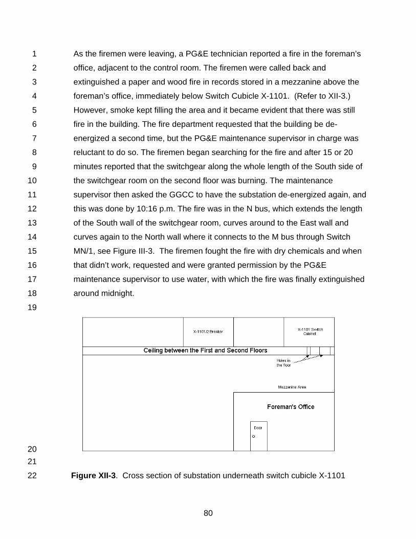
80
As the firemen were leaving, a PG&E technician reported a fire in the foreman’s 1
office, adjacent to the control room. The firemen were called back and 2
extinguished a paper and wood fire in records stored in a mezzanine above the 3
foreman’s office, immediately below Switch Cubicle X-1101. (Refer to XII-3.) 4
However, smoke kept filling the area and it became evident that there was still 5
fire in the building. The fire department requested that the building be de-6
energized a second time, but the PG&E maintenance supervisor in charge was 7
reluctant to do so. The firemen began searching for the fire and after 15 or 20 8
minutes reported that the switchgear along the whole length of the South side of 9
the switchgear room on the second floor was burning. The maintenance 10
supervisor then asked the GGCC to have the substation de-energized again, and 11
this was done by 10:16 p.m. The fire was in the N bus, which extends the length 12
of the South wall of the switchgear room, curves around to the East wall and 13
curves again to the North wall where it connects to the M bus through Switch 14
MN/1, see Figure III-3. The firemen fought the fire with dry chemicals and when 15
that didn’t work, requested and were granted permission by the PG&E 16
maintenance supervisor to use water, with which the fire was finally extinguished 17
around midnight. 18
19
20 21
Figure XII-3. Cross section of substation underneath switch cubicle X-1101 22
81
16. Fire Damage 1 2
The fire destroyed the N bus (See Figure XII-4) and Switch Cubicle X-1101 (See 3
Figure XII-5). Switch cubicles for X-1105, X-1109, X-1121 and X-1153, the 4
cables connecting to them, and the cubicle containing the switch tying the M and 5
N buses were all heavily damaged by fire, smoke and soot. Other equipment on 6
the second floor, including the M bus, the switch cubicles connected to it and the 7
circuit breakers, were contaminated with soot. (Refer to Figure XII-6.) The 115 8
kV equipment on the first floor, the 12.5 kV switchgear on the third floor, and the 9
control room were not damaged. 10
11
12
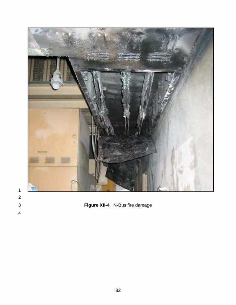
82
1 2
Figure XII-4. N-Bus fire damage 3
4
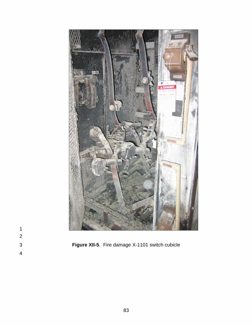
83
1 2
Figure XII-5. Fire damage X-1101 switch cubicle 3
4
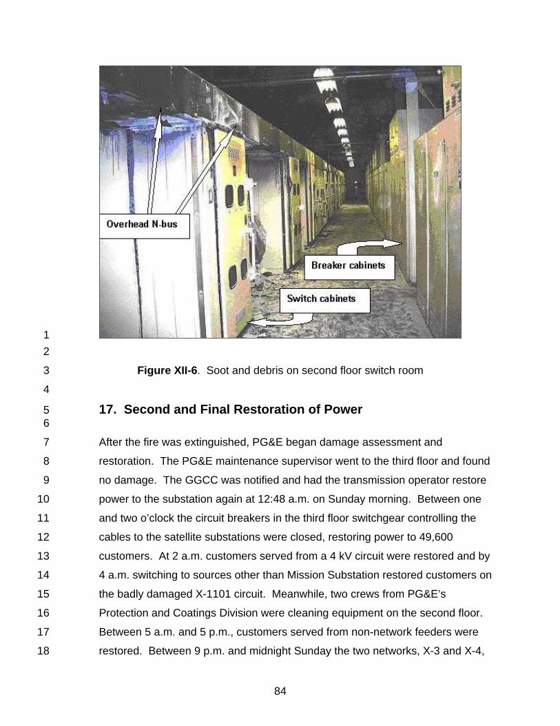
84
1 2
Figure XII-6. Soot and debris on second floor switch room 3
4
17. Second and Final Restoration of Power 5 6
After the fire was extinguished, PG&E began damage assessment and 7
restoration. The PG&E maintenance supervisor went to the third floor and found 8
no damage. The GGCC was notified and had the transmission operator restore 9
power to the substation again at 12:48 a.m. on Sunday morning. Between one 10
and two o’clock the circuit breakers in the third floor switchgear controlling the 11
cables to the satellite substations were closed, restoring power to 49,600 12
customers. At 2 a.m. customers served from a 4 kV circuit were restored and by 13
4 a.m. switching to sources other than Mission Substation restored customers on 14
the badly damaged X-1101 circuit. Meanwhile, two crews from PG&E’s 15
Protection and Coatings Division were cleaning equipment on the second floor. 16
Between 5 a.m. and 5 p.m., customers served from non-network feeders were 17
restored. Between 9 p.m. and midnight Sunday the two networks, X-3 and X-4, 18

85
were re-energized, completing the restoration of power, approximately 30 hours 1
after the first shutdown. 2
3
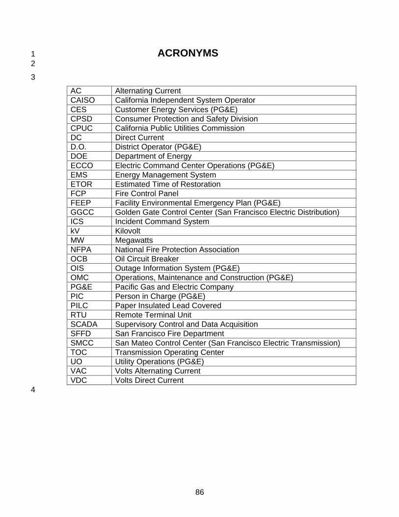
86
ACRONYMS 1 2
3
AC Alternating Current CAISO California Independent System Operator CES Customer Energy Services (PG&E) CPSD Consumer Protection and Safety Division CPUC California Public Utilities Commission DC Direct Current D.O. District Operator (PG&E) DOE Department of Energy ECCO Electric Command Center Operations (PG&E) EMS Energy Management System ETOR Estimated Time of Restoration FCP Fire Control Panel FEEP Facility Environmental Emergency Plan (PG&E) GGCC Golden Gate Control Center (San Francisco Electric Distribution) ICS Incident Command System kV Kilovolt MW Megawatts NFPA National Fire Protection Association OCB Oil Circuit Breaker OIS Outage Information System (PG&E) OMC Operations, Maintenance and Construction (PG&E) PG&E Pacific Gas and Electric Company PIC Person in Charge (PG&E) PILC Paper Insulated Lead Covered RTU Remote Terminal Unit SCADA Supervisory Control and Data Acquisition SFFD San Francisco Fire Department SMCC San Mateo Control Center (San Francisco Electric Transmission) TOC Transmission Operating Center UO Utility Operations (PG&E) VAC Volts Alternating Current VDC Volts Direct Current 4
87
Glossary 1 2
Action Plans/Strategy – Action taken after the event to prevent or reduce the 3 probability of a similar problem occurring in the future or to correct an identified 4 problem and other related problems that may exist. A useful action plan 5 identifies who should do what and when, with a follow up on what strategies were 6 effectively implemented. 7 8 Bus – electrically conductive path, typically a metal pipe or bar, which provides a 9 common connection point for equipment. 10 11 Circuit – conductor or system of conductors through which electric current is 12 intended to flow. 13 14 Circuit Breaker – device used to stop a flow of electricity automatically or 15 manually. Circuit breakers are typically used to protect equipment when current 16 exceeds a set limit or when a short circuit occurs. When a circuit breaker allows 17 electricity to flow, it is closed. When a breaker stops electricity flow, it is open. 18 Once a circuit breaker opens, it must be reset to close it. 19 20 CAISO – California Independent System Operator, authority responsible for the 21 operation and control of the statewide electricity transmission grid. 22 23 Distribution – The local wires, transformers, substations, and other equipment 24 used to distribute and deliver electricity to consumers from the high voltage 25 transmission lines. Distribution voltages typically range from 4 kV up to 60 kV. 26 27 D.O. – District Operator that monitors and operates the electric distribution 28 system from a control center. 29 30 Event – An unplanned major equipment failure that occurred within the PG&E’s 31 electric system. 32 33 Fault– An event such as a short circuit or ground that occurs on a circuit and 34 causes relays and circuit breakers to operate. 35 36 Feeder – electricity distribution line that connects the substation to the 37 distribution network supplying the consumers. 38 39 GGCC – Golden Gate Control Center. Located in Daly City, GGCC district 40 operators manage the PG&E electricity distribution system in San Francisco and 41 Peninsula districts. 42 43 Ground – A fault or unintentional connection that provides a low-resistance path 44 between a point in a circuit and ground. A ground can drastically affect the 45 operation of a circuit. A ground may damage or destroy equipment if excessive 46 current flow results. 47
88
1 N-1 Condition – The loss of a single circuit. 2 3 Network Circuit – circuit with multiple power sources that divide the load 4 demand among the multiple sources. Networks are used to increase reliability in 5 the event that if one source is lost, the other sources can maintain the load 6 demand until all sources are restored. 7 8 Network Protector – device like a circuit breaker used to stop electricity flow. 9 Network protectors open a circuit in the event electric current is too low, too high, 10 or in the wrong direction. 11 12 PILC – Paper Insulated Lead Covered [Cable]. PILC cable is typically composed 13 of three stranded copper conductors: one for each phase of a three- phase 14 electrical circuit. To insulate the phases from one another, each set of stranded 15 conductor is wrapped in layers of oil-impregnated paper, and then bundled 16 together in a lead sheath with a plastic jacket. 17 18 Radial Circuit – circuit with a single power source to supply the load demand. 19 The circuit provides no power if the single source is lost. 20 21 Overcurrent Relay – device which detects an excess of current to automatically 22 operate a circuit breaker. 23 24 Root Cause – The underlying event or condition that, if corrected, would prevent 25 or minimize the probability of recurrence of the problem. 26 27 SCADA – Supervisory Control and Data Acquisition. A network of automated 28 devices and controls that enables remote monitoring and management of 29 electrical system equipment and components. 30 31 Short Circuit – typically, a fault or unintentional connection that provides a path 32 for electric current between phase conductors. A short circuit can be either two 33 or three-phase and drastically affects the operation of a circuit. If a short circuit is 34 not interrupted, damage or destruction of equipment may result. 35 36 SMCC – San Mateo Control Center. SMCC district operators manage the PG&E 37 electricity transmission system in San Francisco and Peninsula districts. 38 39 Substation – point in an electricity distribution system that receives high voltage 40 from transmission lines and reduces it to lower voltage to send out over 41 distribution lines. 42 43 Switch – device to stop the flow of electricity or to change the path of the flow of 44 electricity. 45 46 Total Number of Customers Affected – The total number of bill-paying 47 (metered) customers affected by a momentary or sustained electricity outage. 48
89
1 Transformer – device used to transform voltage levels to facilitate the transfer of 2 power from a generating plant to the customer. Substations use transformers to 3 reduce high transmission voltage to lower distribution voltage. 4 5 Transmission – The interconnecting electric lines that move high voltage 6 electricity from where it is produced to the point of distribution to customers. 7 Transmission voltages range from 60 kV up to 500 kV. 8 9 Trip, Tripping, Tripped - A circuit breaker trip occurs when a closed breaker 10 detects an excessive electrical current and opens to stop the current. 11

Appendix A 1 2
Simplified Single Line Diagram of Mission Substation 3
II
Appendix B 1 2
PG&E Root Cause Analysis of 1996 Mission Substation Fire3

III
Appendix C 1 2
Okonite Company Tests of PILC Cable 3 4