Embed Size (px)
Citation preview

1
INVESTIGATION THE EFFECT OF INLET PORTS DESIGN ON COMBUSTION CHARACTERISTICS AND EMISSION LEVELS OF
DIESEL ENGINES
1Professor, 2MS Student, Department of Mechanical Engineering, Iran University of Science and Technology, Tehran, Iran. 3MS Student, Department of Mechanical Engineering, K. N. Toosi University of Technology, Tehran, Iran. *
ABSTRACT Intake system design as well as inlet ports and valves configuration is of paramount importance in the optimal performance of internal combustion engines. In the present study, the effect of inlet ports design is investigated on OM-457LA diesel engine by using a CFD analysis and the AVL-Fire code as well. A thermodynamic model of the whole engine equipped with a turbocharger and an intercooler is used to obtain the engine initial and boundary conditions which are necessary for performing the three dimensional CFD analysis. The intake stroke as well as the compression and power strokes are included in this three dimensional CFD model. As a mean of validation the performance of the engine model with the base configuration of the inlet ports is compared to the experimental data. Two new alternative configurations for the inlet ports are then investigated with respect to the turbulence levels of the in-cylinder flow and the combustion characteristics as well. Finally it is demonstrated that the optimization of inlet ports geometry plays an important part in the engine efficiency and its emission levels as well. KEYWORDS: Inlet ports configuration, geometry optimization, turbulence level, engine CFD model.
1- INTRODUCTION The interest in utilizing diesel engines is on the increase.
Improvement in the performance as well as the emission levels and the fuel consumption of these engines is therefore inevitable. However, the nonviable level of NOX and soot in such engines is a major difficulty against their usage.
It is well known that the combustion process quality has a great effect on the engine performance. In order to improve this item, several concepts has been explored, which were based on particular parameters in the combustion process, e.g. boost pressure, turbulence level of the combustion chamber, injection timing, and fuel type.
The in-cylinder flow field has a great effect on the engine performance as well as the engine emission levels. For direct injection engines the time of fuel evaporation is so short as well as the time of mixing and ignition processes. That is why in such engines the in-cylinder flow field plays a premier part in the engine performance and its emission level as well. Intake system design and inlet ports configuration is therefore of paramount importance in the optimize performance of the engine. It is stated that in any efficient design of the engine intake system, in order to have a high volumetric efficiency the energy losses of the inlet flow should be minimized. Moreover, in recent engines it is desirable to shorten the combustion duration. Since the in-cylinder gas velocity affect the burning rate, it is bothered to generate swirl and tumble motions during the intake stroke. So that, the burning rate will increase at given engine speeds [1] .
Using a CFD model besides employing the KIVA-3V code, the effect of adding shrouds to the inlet valves on turbulence level of the combustion chamber as well as the combustion characteristics were studied in [2] for a direct injection diesel engine.
The effect of inlet ports geometry on swirl control and inlet ports discharge coefficient has been addressed in [3] and [4]. The inlet ports design for SI engines has been investigated by means of a parametric approach in [5]. To do this, the geometry of the inlet ports was defined using six fundamental parameters. These parameters were selected so that the initial and secondary factors, which define the flow and tumble performance of a port, were included. The aim of this method is to design inlet ports more rapidly.
In the present study, two new alternative inlet port configurations are designed. Employing three dimensional simulations, these two alternatives are compared to the base configuration of the engine inlet ports. The results highlight the advantages of the new inlet port configurations in the terms of combustion characteristics, turbulence levels of the in-cylinder flow, engine performance, and emission levels.
2- THERMODYNAMIC MODELING The aim of thermodynamic modeling is to simulate the
engine performance in order to estimate and recognize its premier operational parameters at given engine operational conditions. There are two reasons to perform the thermodynamic modeling before the three dimensional CFD modeling. In the first place, the initial and boundary
, I. Sohrabias , and E. Sarshari 2 3M. H. Shojaeefard*
Corresponding Author

2
conditions which are necessary for doing the CFD modeling can be obtained by employing this thermodynamic simulation. Secondly, results obtained from this primary simulation can be compared with the results gained from the CFD modeling as a mean of verification.
The thermodynamic modeling is performed using AVL/Boost software. As shown in Fig. 1., this model includes the whole engine, consisting mainly of the ports, the turbocharger, the intercooler, and the inlet manifold. OM-457LA diesel engine which is produced by Daimler-Chrysler Company is studied here, as mentioned before. The specifications of the engine are tabulated in Tab. 1.
Fig. 1: A view of the engine thermodynamic model in AVL/Boost environment.
The compressor map of the engine turbocharger is used to model the thermodynamic behavior of the engine with more degree of accuracy.
Tab. 1: Specifications of the engine. Number of cylinders 6 Cylinder bore 128 mm Displacement 12 Liter Compression ratio 17.25: 1Piston stroke 155 mmMaximum power at the speed of 2000 rpm 220 KW
Fig. 2. and Fig. 3. depict the engine maximum power and torque obtained from the engine thermodynamic model along with the experimental results. The engine maximum power and torque are 220 KW at 2000 rpm and 1250 N.m at 1100 rpm, respectively. The evident result of these figures is the validity of the engine thermodynamic model.
Fig. 2: The engine power, the simulation results along with the experimental results.
Fig. 3: The engine torque, the simulation results along with the experimental results.
The engine brake specific fuel consumption is plotted in Fig. 4. for both simulation results and experimental results as well. In the thermodynamic modeling performed, the blowby gap was assumed to be equal to zero. That is why the power and torque obtained from the simulation are a bit bigger than their experimental amounts. As another result of this assumption, the simulated brake specific fuel consumption is obtained lesser.
Fig. 4: The engine brake specific fuel consumption, the simulation results along with the experimental results.
3- THREE DIMENSIONAL CFD MODELING In order to perform the three dimensional CFD model, the
AVL/Fire software is employed. The simulation is done at the engine speed of 1800 rpm besides considering a full-load operating point. It is well-known that the highest emission level of engines appears at full-load conditions.
Unstructured grids are used to make the computational domain. The generated mesh is reproduced by means of rezone procedure within each time step. The time step is set to
SB1
SB2
PL1
C1 C2 C3 C4 C5 C6MP1
MP2
MP3
MP4
MP5
MP6MP7
CO1
TC1
1
2
3
4
J1 J2 J3 J4 J5 J6
5
67
8
910
11
1213
14
1516
17
1819
20
2122
J7 J8 J9 J10 J11 J12
2324
2526
2728
2930
3132
3334
J13J14
35 36 37 38 39 40
J15
41 4243
85
115
145
175
205
235
700 900 1100 1300 1500 1700 1900 2100
Pow
er [
KW]
Speed [rpm]
Simulation
Experimental
1000
1050
1100
1150
1200
1250
1300
700 900 1100 1300 1500 1700 1900 2100
Torq
ue [
N.m
]
Speed [rpm]
Simulation
Experimental
195
200
205
210
215
220
225
230
700 900 1100 1300 1500 1700 1900 2100
BSFC
[g/
Kw.h
r]
Speed [rpm]
SimulationExperimental
3
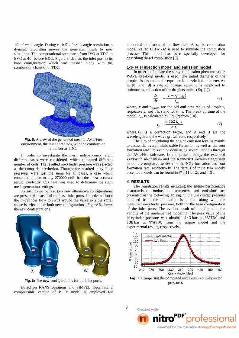
10° of crank angle. During each 5° of crank angle revolution, a dynamic algorithm moves the generated mesh to new situations. The computational step starts from IVO at TDC to EVC at 40° before BDC. Figure 5. depicts the inlet port in its base configuration which was meshed along with the combustion chamber at TDC.
Fig. 5: A view of the generated mesh in AVL/Fire
environment, the inlet port along with the combustion chamber at TDC.
In order to investigate the mesh independency, eight different cases were considered, which contained different number of cells. The resulted in-cylinder pressure was selected as the comparison criterion. Thought the resulted in-cylinder pressures were just the same for all cases, a case which contained approximately 270000 cells had the most accurate result. Evidently, this case was used to determine the right mesh generation settings.
As mentioned before, two new alternative configurations are presented instead of the base inlet ports. In order to force the in-cylinder flow to swirl around the valve axis the spiral shape is selected for both new configurations. Figure 6. shows the new configurations.
Fig. 6: The new configurations for the inlet ports.
Based on RANS equations and SIMPEL algorithm, a compressible version of model is employed for
numerical simulation of the flow field. Also, the combustion model, called ECFM-3Z is used to simulate the combustion process. This model has been specially developed for describing diesel combustion [6].
1-3- Fuel injection model and emission model In order to simulate the spray combustion phenomena the
WAVE break-up model is used. The initial diameter of the droplets is assumed to be equal to the nozzle hole diameter. As in [8] and [9] a rate of change equation is employed to estimate the reduction of the droplets radius (Eq. (1)).
(1)
where, and are the old and new radius of droplets, respectively, and is stand for time. The break-up time of the model, , is calculated by Eq. (2) from [10].
3.762 .Λ. Ω
(2)
where, is a correction factor, and Λ and Ω are the wavelength and the wave growth rate, respectively.
The aim of calculating the engine emission level is mainly to assess the overall nitric oxide formation as well as the soot formation rate. This can be done using several models through the AVL/Fire software. In the present study, the extended Zeldovich mechanism and the Kennedy/Hiroyasu/Magnussen model are employed to describe the NOX formation and soot formation rate, respectively. The details of these two widely accepted models can be found in [7], [11], [12], and [13].
4- RESULTS The simulation results including the engine performance
characteristic, combustion parameters, and emissions are presented in the following. In Fig. 7. the in-cylinder pressure obtained from the simulation is plotted along with the measured in-cylinder pressure, both for the base configuration of the inlet ports. The evident result of this figure is the validity of the implemented modeling. The peak value of the in-cylinder pressure was obtained 143 bar at 8°ATDC and 138 bar at 9°ATDC from the engine model and the experimental results, respectively.
Fig. 7: Comparing the computed and measured in-cylinder pressures.
-101030507090
110130150
240 270 300 330 360 390 420 450 480
Pres
sure
[ba
r]
Crank Angle [deg]
ExperimentalAVL Fire

4
The swirl motion of the in-cylinder flow is depicted in Fig. 8. for the base configuration of inlet ports as well as both alternatives. As it can be seen both alternative configurations provide a higher swirl motion rather than the base configuration. The swirl obtained applying the configuration (B) is about 32% higher than that of the base configuration.
Fig. 8: The swirl motion for different inlet ports configurations.
According to Tab. 2., the mass of the inlet flow is increased applying the alternative configurations. The combustion process is therefore done leaner and the equivalence ratio is increased. Also, the engine power is computed for different configurations of inlet ports and presented in Tab. 2. As it can be seen, the engine power is decreased a bit while applying the alternative configurations.
Tab. 2: Comparing the inlet flow mass, equivalence ratio, and engine power for different inlet ports configurations.
Inlet flow mass (Kg)
Equivalence ratio
Power (KW)
Base configuration 0.005366 0.480 283 Configuration (B) 0.005433 0.471 273 Configuration (C) 0.005401 0.478 278
Since the swirl motion of the in-cylinder flow has increased, the peak in-cylinder temperature is decreased applying the alternative configurations (Fig. 9.). The fuel droplets can therefore penetrate more simply in the in-cylinder flow. This results in a leaner and steadier combustion process besides preventing any sudden in-cylinder temperature increment.
Fig. 9: The mean in-cylinder temperature for different inlet ports configurations.
Applying the alternative configurations causes some serious changes in the flow field, including changing the intake flow regime during the intake stroke, and increasing the volumetric efficiency as well as the swirl motion during the compression stroke. As an evident result of these changes, the heat transfer between the flow and the engine wall increases. That is why the maximum heat release rate as well as the total heat release decreases (Fig. 10.). As mentioned before using the alternative configurations results in a steadier combustion process. The ramp of the heat release rate diagram therefore decreases applying the alternative configurations. However the total heat release decreases, the likelihood of nock occurrence decreases.
Fig. 10: Comparison of the heat release rate.
The computed results associated with the engine emission levels are demonstrated in the following. The NOX formation is highly dependent on the in-cylinder temperature [14]. As showed before, lower temperatures occur applying the alternative configurations. The NOX formation is therefore lesser for both alternative configurations than for the base configuration. This can be seen explicitly in Fig. 11.
Fig. 11: Comparison of NOX formation.
Each one of the presented inlet ports configurations results in different engines which their combustion chambers at 20°ATDC are shown in Fig. 12. The combustion chamber of the engine equipped with the base configuration of inlet ports is shown in Fig. 12.a. Also, Fig. 12.b., and 12.c. relate to the engines with configuration (B), and configuration (C), respectively. The aim of these figures is to show section views of the combustion chambers in which the equivalence ratios are depicted. Since the peak in-cylinder temperature occurs at
-3300
-2800
-2300
-1800
-1300
-800
-300
200
0 50 100 150 200 250 300 350 400 450 500
Swirl
[1/
min
]
Crank angle [deg]
Base configurationConfiguration (B)Configuration (C)
200
700
1200
1700
2200
300 350 400 450 500
Tem
pera
ture
[K]
Crank angle [deg]
Base configurationConfiguration(B)Configuration (C)
0
50
100
150
200
250
300 325 350 375 400 425 450
Hea
t re
leas
e [j
/deg
]
Crank angle [deg]
Base configuration
Configuration (B)
Configuration (C)
0
5
10
15
20
25
350 370 390 410 430 450 470 490
NO
[gr
/kg
fuel
]
Crank angle [deg]
Base configuration
Configuration (B)
Configuration (C)

5
20°ATDC, this is the most viable crank angle in order to study the engine emission level.
Fig. 12: Comparison of the equivalence ratios.
According to Fig. 12. the equivalence ratio is lesser for the base configuration. That is why the in-cylinder temperature as well as the NOX formation is higher for this configuration. Figure 13. and 14. show the section views of the combustion chambers in the same order of Fig. 12. in which the flow temperature and NOX formation can be seen, respectively.
Fig. 13: Comparison of the in-cylinder temperature.
Fig. 14: Comparison of the NOX formation.
It can be seen in Fig. 14. that the nitric oxide mass fraction is lesser in the case of applying the alternative configurations.
The engine soot formation rate is demonstrated in Fig. 15. for the presented inlet ports configurations. However the soot formation rate is approximately the same for all of the configurations presented, applying the configuration (C) decreases the soot formation rate slightly.
Fig. 15: Comparison of the soot formation rate.
The simulated results for the engine emission levels are tabulated as a conclusion in Tab.3. It can be seen that applying the alternative configurations for the engine inlet ports results in a lesser formation of nitric oxide and unburned hydrocarbons. The soot formation rate is almost the same for all the configurations presented, though the configuration (C) results in a more viable soot formation rate.
Tab. 3: Comparing the nitric oxide formation, soot formation rate, and unburned hydrocarbon for different inlet ports configurations.
Nitric oxide
(gr/ Kw. h)
Soot formation
rate (mgr/ Kw. h)
Unburned hydrocarbon (gr/ Kw. h)
Base configuration 4.497 10.14 1.947 Configuration (B) 0.913 13.96 1.750Configuration (C) 1.066 7.054 1.847
0
0.2
0.4
0.6
340 360 380 400 420 440 460 480
Soot
[gr
/ kg
fue
l]
Crank angle [deg]
Base configuration
Configuration (B)
Confiuration (C)
Base
B
C
Base
B
C
Base
B
C

6
5- CONCLUSIONS In the study presented the effect of inlet ports
configurations on the OM-457LA diesel engine was investigated in the terms of engine performance and emission levels as well. To do this, a thermodynamic model of the whole engine was developed by means of the AVL/Boost software. The aim of this thermodynamic model was mainly to provide the initial and boundary conditions of the engine operation which were necessary for the 3D CFD modeling. Thereafter, using the AVL/Fire code the 3D CFD model of the engine with the base inlet ports configurations as well as two alternative configurations was developed. Comparing the measured and computed in-cylinder pressures was used as a mean of validation of this 3D CFD model.
The simulation results were demonstrated applying the alternative configurations for the inlet ports increases the in-cylinder flow swirl. This provides more viable air/fuel mixture by which a steadier combustion will obtain. Furthermore, the mean in-cylinder temperature as well as the maximum heat release rate decreases which results in a lesser nitric oxide formation and soot formation rate. Among the configurations examined, it was seen that the configuration (B) and the configuration (C) lead to the least amount of nitric oxide and soot, respectively. However decrease in the engine power was inevitable in such optimizations, applying both alternative configurations results in the inconsiderable decreases. Ultimately, it can be concluded that the configuration (C) is the most viable configuration among the configurations examined. The study presented explored the method by which the engine inlet ports configurations are optimized by means of virtual simulations. Implementing this method can decrease the costs and time associated with such an optimization in comparison with the classical test base processes.
REFERENCES [1] Fontana, G., Galloni, E., Palmaccio, R., Strazzullo, L.,
and Vittorioso, G., 2003, “Development of a New Intake System for a Small Spark-Ignition Engine. Modeling the Flow Through the Inlet Valve”, SAE Technical Paper, 2003-01-0369.
[2] Ramadan, B., 2003, “A Study of Swirl Generation in DI Engines Using KIVA-3V”, Kettering University.
[3] Cantore, G., Fontanesi, S., Montorsi, L., and Ortolani, P., 2004, “ Comparison between Steady and Unsteady CFD Simulation of Two Different Port Designs in a Four Valve HSDI Diesel Engine: Swirl Intensity and Engine Permeability”, ASME Technical Paper, Proceedings of ICEF04 Conference.
[4] E. Mattarelli, L. Montorsi, S. Fontanesi , "Numerical analysis of swirl control strategies in a four valve HSDI diesel engine", 2004 Fall Technical Conference of the ASME Internal Combustion Engine Division, ICEF2004-909.
[5] Blaxill, H., Downing, J., Seabrook, J., & Fry M., 1999 “A Parametric Approach to Spark-Ignition Engine Inlet-Port Design”, SAE Technical Paper Series, 1999-01-0555.
[6] Tatschl, R., Pachler, K., Fuchs, H., and Almer, W., 1995, ” Multidimensional Simulation of Diesel Engine Combustion- Modeling and Experimental Verification”, Proceedings of the Fifth Conference Named The Working Process of the Internal Combustion Engine.
[7] AVL FIRE User Manual Version 2008.
[8] Reitz, R.D., and Diwakar, J., 1986, “Effect of Drop Break-up on Fuel Sprays”, SAE Technical Papers Series, 860469.
[9] Reitz, R.D., and Diwakar, J., 1987, “Structure of High-Pressure Fuel Sprays”, SAE Technical Papers Series, 870598.
[10] Wakisaka, T., NGUYEN T. T., OKUDE K., and ISSHIKI Y., 2001, “Numerical Prediction of Mixture Formation and Combustion Processes in Premixed Compression Ignition Engines”, COMODIA, Japan.
[11] Zeldovich, Y. B., Sadovnikov, P. Y. and Frank-Kamenetskii, D. A., 1947, “Oxidation of Nitrogen in Combustion”, Academy of Sciences of USSR, Institute of Chemical Physics, Moscow-Leningrad.
[12] Magnussen, B.F., and Hjertager, B.H., 1977, “On mathematical modeling of turbulent combustion with special emphasis on soot formation and combustion”, Sixteenth International Symposium on Combustion.
[13] Hiroyasu, H., and Nishida, K., 1989, “Simplified Three Dimensional Modeling of Mixture Formation and Combustion in a DI Diesel Engine”, SAE Technical Paper Series, 890269.
[14] Pulkrabek W. W., 2004, Engineering Fundamentals of the Internal Combustion Engine, 2n Edition, Prentice Hall.
[15] Jafarmadar, S., Barzegar, R., and Shafee., S., 2009, “Three- Dimensional Modeling of Combustion Process, Soot and NOX Formation in a Direct-Injection Diesel Engine”, Journal of Engine Research, Vol. 14, pp 35-42, ISSN 1735-5214.