Embed Size (px)
Citation preview

Investigations of Graphite Current Collectors(part 1)
and Metallic Lithium Anodes(part 2)
Nancy Dudney (PI)Oak Ridge National Laboratory
Material Science and Technology Division
February 28, 2008
Andrew Kercher, Jim Kiggans, Sea Hoon Park*, and Terry Tiegs*
*former team members
This presentation does not contain any proprietary or confidential information.
OAK RIDGE NATIONAL LABORATORY U. S. DEPARTMENT OF ENERGY
22008 DOE BATT program review
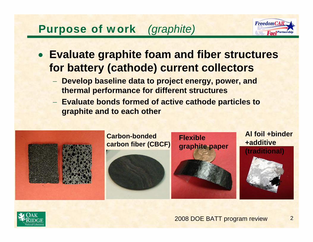
Purpose of work (graphite)
• Evaluate graphite foam and fiber structures for battery (cathode) current collectors − Develop baseline data to project energy, power, and
thermal performance for different structures − Evaluate bonds formed of active cathode particles to
graphite and to each other 25
mm
AR LQI
Graphite foams Carbon-bonded carbon fiber (CBCF)
Flexible graphite paper
Al foil +binder +additive (traditional)
32008 DOE BATT program review
15µm
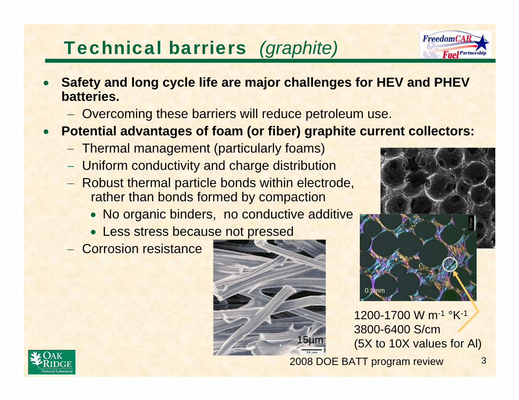
Technical barriers (graphite)
• Safety and long cycle life are major challenges for HEV and PHEVbatteries. − Overcoming these barriers will reduce petroleum use.
• Potential advantages of foam (or fiber) graphite current collectors: − Thermal management (particularly foams) − Uniform conductivity and charge distribution − Robust thermal particle bonds within electrode,
rather than bonds formed by compaction • No organic binders, no conductive additive • Less stress because not pressed
− Corrosion resistance
0.5mm
1200-1700 W m-1 °K-1
3800-6400 S/cm (5X to 10X values for Al)
42008 DOE BATT program review
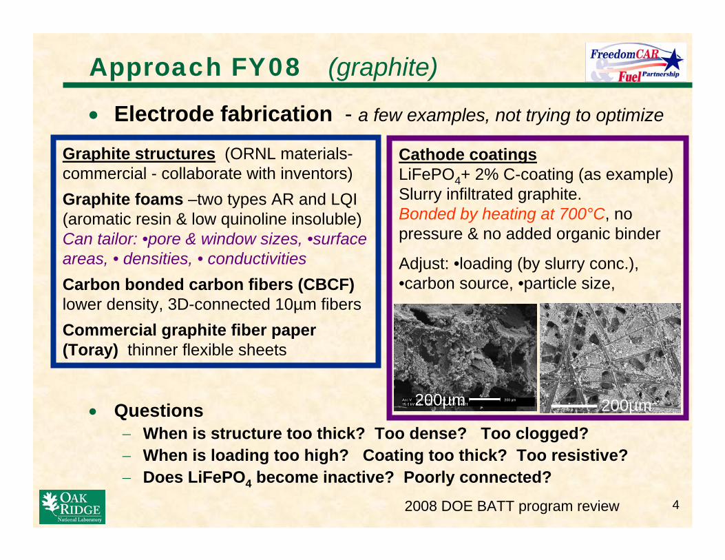
Approach FY08 (graphite)
• Electrode fabrication - a few examples, not trying to optimize
• Questions − When is structure too thick? Too dense? Too clogged? − When is loading too high? Coating too thick? Too resistive? − Does LiFePO4 become inactive? Poorly connected?
Graphite structures (ORNL materialscommercial - collaborate with inventors) Graphite foams –two types AR and LQI (aromatic resin & low quinoline insoluble) Can tailor: •pore & window sizes, •surface areas, • densities, • conductivities Carbon bonded carbon fibers (CBCF) lower density, 3D-connected 10µm fibers Commercial graphite fiber paper (Toray) thinner flexible sheets
Cathode coatings LiFePO4+ 2% C-coating (as example) Slurry infiltrated graphite. Bonded by heating at 700°C, no pressure & no added organic binder
Adjust: •loading (by slurry conc.), •carbon source, •particle size,
200µm200µm
Approach FY08 (graphite)
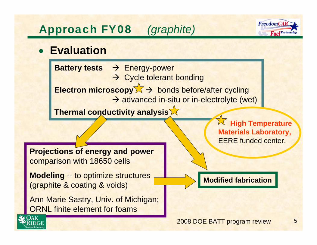
• Evaluation
Battery tests Æ Energy-power Æ Cycle tolerant bonding
Electron microscopy Æ bonds before/after cycling Æ advanced in-situ or in-electrolyte (wet)
Thermal conductivity analysis High Temperature
Materials Laboratory, EERE funded center.
Projections of energy and power comparison with 18650 cells
Modeling -- to optimize structures (graphite & coating & voids) Modified fabrication
Ann Marie Sastry, Univ. of Michigan; ORNL finite element for foams
2008 DOE BATT program review 5

62008 DOE BATT program review
0% 10% 20% 30% 40% 50% 60% 70% 80%
0 20 40 60 80 100 Cycle
Li U
tiliz
atio
n (%
)
DischargeCharge
0%
10%
20%
30%
40%
50%
0 20 40 60 80 100 Cycle
Li u
tiliz
atio
n (%
)
Discharge Charge
Accomplishments (graphite)
1mm AR foam
5mm LQI foam
Cells are 1-6mAh/cm2. Arrow shows 1mAh/cm2 0%
10% 20% 30% 40% 50% 60% 70% 80% 90%
0 20 40 60 80 100 Cycle
Li u
tiliz
atio
n (%
)
Discharge Charge
1mm CBCF
0%
10%
20%
30% 40%
50%
60%
70%
80%
0 20 40 60 80 100 Cycle
Li u
tiliz
atio
n (%
)
Discharge Charge
1mm LQI foam
C/30
C/30 C/30
C/30
C/2
C/2
C/2
C/2
Cell: Li anode (Ni) LiPF6(EC+EMC)
or (EC+DMC) Celgard LIFePO4-C, Al wire
• Good cycling, so thermal bonds of LiFePO4 on graphite are robust. − Little loss of active material with >100 cycles. − Small increase of cell resistance. Lithium degradation also contributes. − Early results published, Proc. Electrochem. Soc.

72008 DOE BATT program review
1
10
100
1000
0.1 1 10 100 1000 10000 Specific Power (mW/g)
Spec
ific
Ener
gy (m
Wh/
g)
1 mm graphite foam (~1.5mm pores)5 mm graphite foam (~1.5mm pores)5 mm graphite foam (~0.5mm pores)1 mm CBCF 5 mm CBCF 5 mm CBCF fine LiFePO4 2x slurry
defined at 2.8V
Accomplishments (graphite)
• Energy and power assessed
• Power is best for − thin samples (1mm) − fibers structures
• Max. energy varies as: − Wt% of LiFePO4 (15
58%) − LiFePO4 utilization
(85-140 mAh/g) − Source of 2 wt%
carbon • More concentrated
slurries will further increase wt %
Selected samples – illustrate trends for different supports and slurries
K2 Energy Solutions

2008 DOE BATT program review
Accomplishments (graphite)
• Compare cathodes with commercial technology
For cathode + the current collector only
K2 Energy Solutions18650
Projected AR foam
Projected LQI foam
LiFePO4 wt. (g) 12 12 12 LiFePO4 / C wt.ratio 3X current 4X current Current collector wt. (g) 1.5–2.6** Al foil 4.8 foam 9.4 foam Binder+additive (g) (1-3, est.) 0 0 Energy (mWh/g) 250 – 310 270 210 LiFePO4 coating (µm-thick) 50* 140* Heat transport (W/°K) 0.035 – 0.062 0.19 0.75 Foam pore diameter (µm) 500 1500 Foam surface area (cm2) 1250 470 Thermal cond. (W/m/°K) 235 50 180
**For energy & power cells. *For 50% dense. 8

92008 DOE BATT program review
Accomplishments (graphite) • Improved slurry and coating processes
− Slurry concentration increased 7-fold, still very fluid • Future samples will have higher energy density with single coat
− LiFePO4 particle size reduced to 0.3-0.8µm by Spex milling with0.3mm media. • Anticipate further reduction with 2-stage milling
− Carbon precursors yielding graphitic carbon perform better thanthose giving glassy carbon • Anticipate improvement with > 2 wt.% carbon
1515µµ mm

Future work and Tech Transfer (graphite)
• Characterize bonds with active material − Use electron microscopy and dual beam FIB − Extend electrical cycling beyond 100 cycles (need to add
fresh Li and electrolyte) • Project energy and power densities
− Compare to existing technology − Demonstrate performance with higher LiFePO4 loading
• Advanced modeling − Identify directions where large improvement possible
• Technology transfer opportunities − ORNL has IP position in graphite structures, motivation to
develop battery application
Milestones for FY08
2008 DOE BATT program review 10

Investigations of Graphite Current Collectors (part 1)
and Metallic Lithium Anodes (part 2)
This presentation does not contain any proprietary or confidential information.
OAK RIDGE NATIONAL LABORATORY U. S. DEPARTMENT OF ENERGY

Purpose of work (lithium anode)
• Understand interface instabilities at the lithium metal anode when cycled with a liquid or polymer electrolyte. − Current models for lithium dendrite initiation
are inadequate.− Investigate roughening with pristine lithium
surface formed by vacuum evaporation.
2008 DOE BATT program review 12

Technical barriers (lithium anode)
• PHEV and HEV applications requires batteries with higher energy densities − Lithium metal 3.8Ah/g, carbons 0.37Ah/g− Lithium metal anodes give maximum cell voltage
• Technical Barrier – lithium roughening leads to rapid degradation, impacting safety and cycle lifeperformance − Loss of active material, decrease capacity, increase of
cell resistance − Possible shorting if lithium dendrites form and propagate
through polymer or liquid electrolyte − Finely divided lithium (mossy lithium) is chemically
reactive, but electrochemically inactive • Solution will enable next generation battery and
petroleum savings for transportation
2008 DOE BATT program review 13

2008 DOE BATT program review 14
Approach FY08 (lithium anode) • Approached has changed. • Initial approach
− Study dendrite initiation on very smooth and clean Li • Emphasize current density, time,
surface features • New approach – recognize effect of SEI
− Study growth and ‘breakdown’ of SEI layer at Li – electrolyte interface • Use very smooth surfaces. replace when roughened • Incorporate surface coatings and barrier layers • Use electrochemical & quartz crystal microbalance tests • SEM observation of surface and fracture edge after aging
• Complements Alan West’s program • Collaboration with High Temperature Materials Laboratory for
developing in-situ SEM and STEM techniques
100 µm
tilted
Cell details: WE=Li film on Ni, CE=Li ribbon or film; RE=Li on Ni wire LiPF6(EC+EMC) or (EC+DMC); no separator - 0.5mm gap; Teflon

152008 DOE BATT program review
Accomplishments (lithium anode) • Abandoned investigation focused on initiation and growth
of dendrites − Inconclusive results of current density, time to initiation,
surface feature investigation − Form and location of dendrites varied − Deposition and also Li removal initiated at spots on surface
200x
100µm
2000x
10µm 20x 1mm
100µm
200x Li
deposition
Li removal
Li deposition at grain boundaries
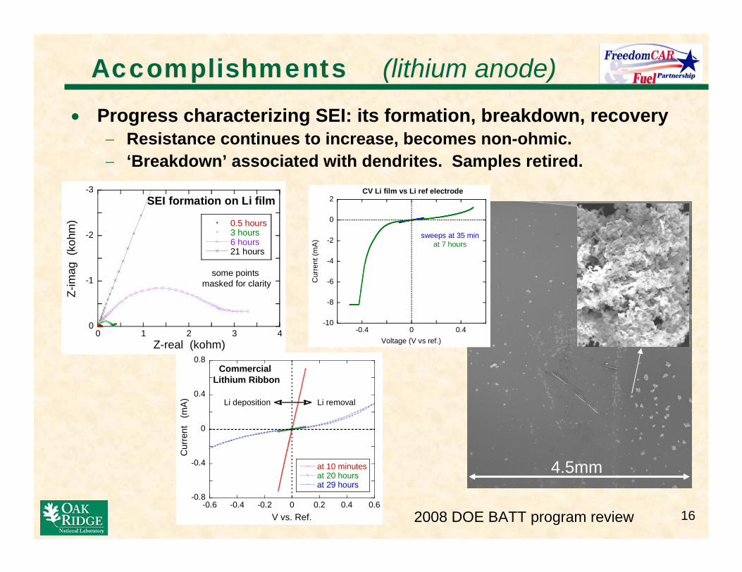
Accomplishments (lithium anode)
• Progress characterizing SEI: its formation, breakdown, recovery − Resistance continues to increase, becomes non-ohmic. − ‘Breakdown’ associated with dendrites. Samples retired.
-3 CV Li film vs Li ref electrode 2SEI formation on Li film 00.5 hours
3 hours -2 6 hours 21 hours
some points -1 masked for clarity C
urre
nt (m
A) sweeps at 35 min -2 at 7 hours
-4
-6
-8
-10 0 0 1 2 3 4 -0.4 0 0.4
Z-real (kohm) Voltage (V vs ref.)
0.8 Commercial
Lithium Ribbon 0.4
Cur
rent
(m
A) Li deposition Li removal
0
-0.4 at 10 minutes 4.5mmat 20 hours at 29 hours
Z-im
ag (
kohm
)
-0.8 -0.6 -0.4 -0.2 0 0.2 0.4 0.6
V vs. Ref. 2008 DOE BATT program review 16

172008 DOE BATT program review
Accomplishments (lithium anode) • Quartz crystal microbalance and direct observation to evaluate SEI
layer formation kinetics − Resistance may increase due to density,
composition, or thickness
0
20
40
60
80
0 1 2 3 4 5
SEI formation, measured at 0.1Hz
evaporated Li film Li ribbon Aesar bare Ni, no Li Li ribbon 10X scaled
Z re
al @
0.1H
z (k
ohm
)
Sq. root time (h 1/2)
Lipon & Nifused silica
Li film
SEI
Fracture edge Ta coated
SEI
Li
0.2
0.3
0.4
0 200 400
Microbalance - SEI growth on Li film
mg
1
1.5
2
Mas
s (m
g)
Time (m)
0.5μm film on Ni/Cr/quartz crystal
Thick
ness
(μm
)
SEI thickness assuming (1.4g/cm3)
1µm
V v
s. R
ef.
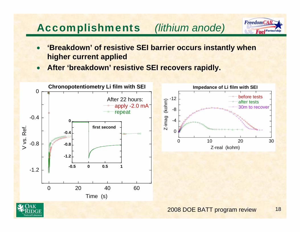
Accomplishments (lithium anode)
• ‘Breakdown’ of resistive SEI barrier occurs instantly when higher current applied
• After ‘breakdown’ resistive SEI recovers rapidly.
Chronopotentiometry Li film with SEI Impedance of Li film with SEI 0
before tests -12 After 22 hours:
Z-im
ag (
kohm
)
after tests apply -2.0 mA 30m to recover -8
-4
0
repeat -0.4 0
first second -0.4
0 10 20 30 -0.8 -0.8 Z-real (kohm)
-1.2
-0.5 0 0.5 1-1.2
0 20 40 60
Time (s)
2008 DOE BATT program review 18
192008 DOE BATT program review
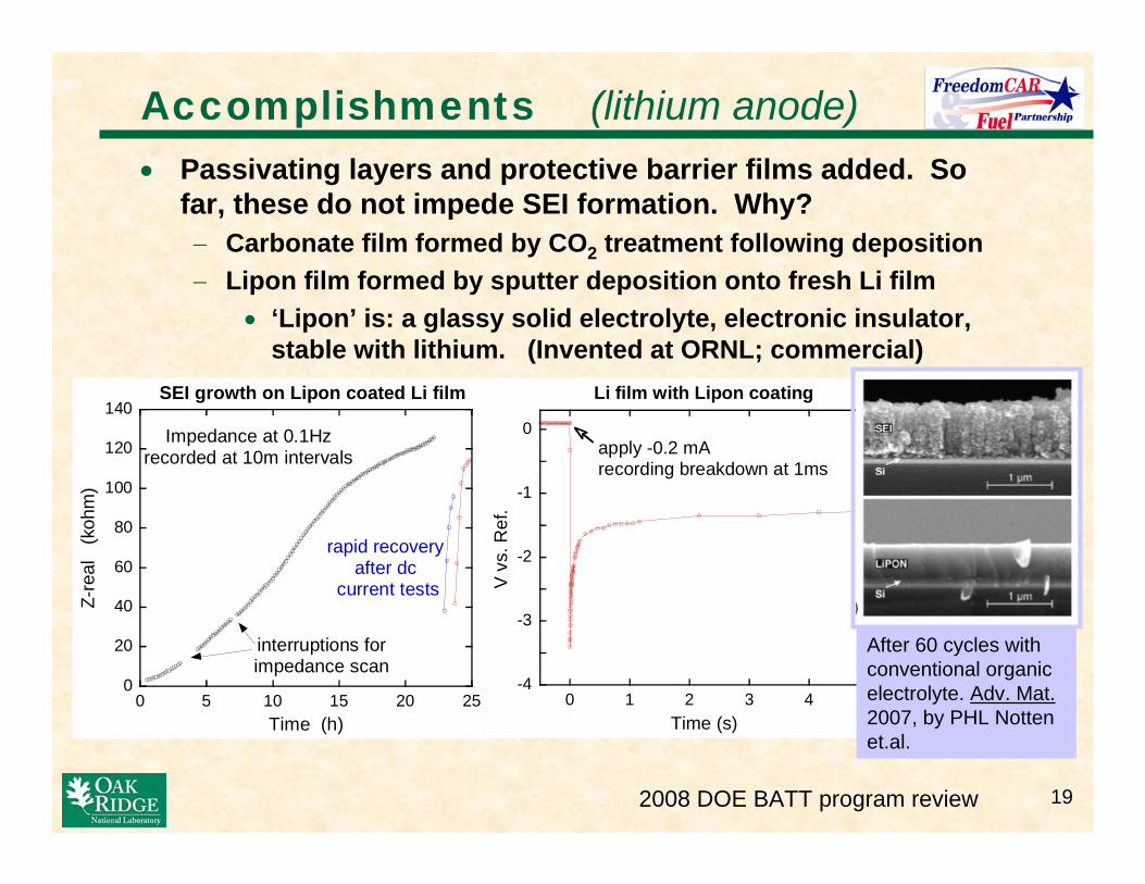
Accomplishments (lithium anode)
-4
-3
-2
-1
0
0 1 2 3 4 5
Li film with Lipon coating
V v
s. R
ef.
Time (s)
apply -0.2 mA recording breakdown at 1ms
0
20
40
60
80
100
120
140
0 5 10 15 20 25
SEI growth on Lipon coated Li film
Z-re
al
(koh
m)
Time (h)
interruptions for impedance scan
rapid recovery after dc
current tests
Impedance at 0.1Hz recorded at 10m intervals
• Passivating layers and protective barrier films added. So far, these do not impede SEI formation. Why? − Carbonate film formed by CO2 treatment following deposition − Lipon film formed by sputter deposition onto fresh Li film
• ‘Lipon’ is: a glassy solid electrolyte, electronic insulator, stable with lithium. (Invented at ORNL; commercial)
After 60 cycles with conventional organic electrolyte. Adv. Mat. 2007, by PHL Notten et.al.
Future work and Tech Transfer (lithium)
• Evaluate the SEI formation for Li in contact with an organic electrolyte. − Model for lithium roughening based on SEI breakdown − Resolve effect of Lipon barrier on SEI
• New techniques for lithium and SEI study − Load lock to XPS, FTIR − Dual beam FIB − In-situ or ‘wet’ study by electron microscopy
(collaboration with HTML staff) • Initiate collaboration with teams designing new electrolytes
Milestones for FY08
2008 DOE BATT program review 20
212008 DOE BATT program review
Summary (graphite and lithium anode projects) • Potential – enable the next generation Li-based batteries • Graphite current collectors for thermal management and
improved safety − Initial results of LiFePO4 on graphite cathodes promising − Projections Æ competitive energy density & good thermal transport − Graphite foams/fiber materials from ORNL are commercial
• Lithium metal anodes for much higher energy density. − Insight into roughening of interface, by shifting focus to SEI
formation and breakdown and effect of Lipon barrier, rather thandendritic growth
• Apply resources of ORNL’s High Temperature Materials Laboratory, in particular electron imaging, to both projects
• FY08 − Investigate thermal bonds of cathode particles coating graphite − Use models and experiments to project performance of optimized
cathode coating and graphite structure − Determine impact of SEI formation on roughening of lithium


![Balra: Double Cab / Graphite Grey Metallic [U28] · 2019. 9. 17. · is viszi az út, az új L200 kormánya mögött mindig magabiztosnak érezheti magát. Balra: Double Cab / Graphite](https://img.pdfslide.net/doc/110x75/6030a19f28564f0d4964a24c/balra-double-cab-graphite-grey-metallic-u28-2019-9-17-is-viszi-az-t.jpg)