Embed Size (px)
Citation preview
TECHNICAL PAPER
Investigations on characteristics of micro/meso scale gas foiljournal bearings for 100–200 W class micro power systems usingfirst order slip velocity boundary conditions and the effectiveviscosity model
Skylab P. Bhore • Ashish K. Darpe
Received: 7 June 2012 / Accepted: 21 July 2012 / Published online: 11 August 2012
� Springer-Verlag 2012
Abstract In this paper, a modified compressible Rey-
nolds equation for micro/meso scale gas foil journal bear-
ings considering first order slip and effective viscosity
under rarefied flow conditions is presented. The influence
of rarefaction effect on the load carrying capacity, attitude
angle, speed and frequency dependent stiffness and
damping coefficients, modal impedance, natural frequen-
cies and unbalance response is studied. From numerical
analysis, it has been found that there is significant change
in all the static and dynamic characteristics predicted by
the no-slip model and model with effective viscosity. There
is also a considerable difference between the values pre-
dicted by a model with effective viscosity and a model
without effective viscosity. For a given eccentricity ratio,
the influence of effective viscosity on load carrying
capacity and attitude angle is more significant for the
typical operating speed range of micro/meso scale gas
turbines. The influence of effective viscosity decreases
with increase in compliance of bearing structure. Similarly,
the influence of effective viscosity on frequency dependent
stiffness and damping coefficients increases with excitation
frequency ratio. Significant change in natural frequency,
modal impedance and unbalance response for model with
no slip and slip with effective viscosity is observed. The
influence of effective viscosity is found to be significant
with increase in Knudsen number.
List of symbols
a Accommodation coefficient
c Damping (Ns/m)
C Bearing radial clearance (m)
CB Dimensionless bump damping coefficient (gKB/
m)
d Gas molecule diameter (m)
e Unbalance eccentricity (m)
E Young’s modulus for bump foil (N/m2)
f (Kn) Effective viscosity coefficient
feX, feY External force in X and Y direction (N)
fX, fY Bearing reaction force in X and Y direction (N)
h Dimensionless film thickness (h/C)
h Gas film thickness (m)
k Stiffness (N/m)
ks_modal Critical modal stiffness (N/m)
Kf Bump foil stiffness (N/m3)
K Dimensionless bearing stiffness coefficient
KB Dimensionless bump stiffness coefficient (1/a)
Kn Knudsen number
lo Bump half length (m)
L Bearing length (m)
mr Rotor mass (kg)
NA Avogadro’s number
Ns Natural frequency (rpm)
pa Atmospheric pressure (N/m2)
p Dimensionless pressure (p/pa)
R Bearing radius (m)
R* Universal gas constant
So Bump pitch (m)
tb Bump foil thickness (m)
ts Dimensionless time (xt)
T Temperature (oK)
U0 Velocity (m/s)
z Dimensionless axial coordinate (z/R)
a Dimensionless compliance of bump foil [(2paSo/
CE)(lo/tb)3(1-t2)]
S. P. Bhore (&) � A. K. Darpe
Department of Mechanical Engineering, Indian Institute
of Technology Delhi, New Delhi 110016, India
e-mail: [email protected]
123
Microsyst Technol (2013) 19:509–523
DOI 10.1007/s00542-012-1639-1
d Dimensionless foil deflection
x Angular velocity of shaft (rad/s)
xs Excitation frequency (rad/s)
ø Attitude angle
øp Rarefaction coefficient
eX, eY Eccentricity ratios in X and Y direction
f Dimensionless bearing load parameter
g Loss factor for bump foil material
K Bearing number [(6lx/pa)(R/C)2]
q Density of gas (kg/m3)
l Viscosity of gas (Ns/m2)
m Excitation frequency ratio (xs/x)
k Molecular mean free path (m)
t Poisson’s ratio for bump foil
w Surface correction factor
Subscript
0 Static
X and Y Direction
eff Effective
1 Introduction
Recent developments in micro/meso scale gas turbines
have given new promises to the world. These gas turbines
can be used in many potential applications of micro/meso
scale power generation units. These days, the use of por-
table electronic devices has tremendously increased in our
society. Several smart and small size machines have been
developed to run on batteries. The batteries are highly
ineffective and having low energy density (energy per unit
mass of the system). It cannot supply continuous power as
it needs frequent charging and time of charging can be
considerable. It is envisaged that the micro and meso scale
gas turbines can be used as continuous power supply for
several applications viz. micropower generation for robots,
micro and nano satellites, micro systems, hybrid energy
system with fuel cells, unmanned air vehicles (UAVs), etc.
(Bhore and Darpe 2012).
The silicon based micro gas turbine was developed in
MIT with lithographic manufacturing technologies. The
design of micro gas bearings used in such turbine is chal-
lenging and inherently it requires a very small length to
diameter (L/D) ratio due to structural properties of silicon.
Silicon is a brittle material and has limited life during rotor
vibration and crashes. It is not a very desirable bearing
material and exhibits high wear rates, high coefficients of
friction and poor stiction characteristics (Epstein 2003;
Breuer 2001). To circumvent the problems associated with
silicon and to enhance the reliability of system, few
attempts to manufacture such systems in metals was car-
ried out (Isomura et al. 2005, 2006; Peirs et al. 2003).
Micro-milling, micro-elctro discharge machining, micro-
molding and more recently X-ray lithography and LIGA
processes have been used to manufacture the gas turbine in
metals (ceramics) for 100–200 W class micro power sys-
tem (Lee et al. 2007; Salehi et al. 2007; Kim et al. 2009).
This gives more freedom in manufacturing and helps to
reduce the operating speed below one million rpm with
little increased impeller size of 10–15 mm and bearing size
of 5–7 mm. The gas turbine with the above mentioned size
is called meso scale gas turbine or palm-sized gas turbine.
The support for the high speed rotor also needs special
consideration compared to conventional gas turbine; the
operating speed of meso scale gas turbine is very high and
ranges between 500,000 and 1,000,000 rpm. The temper-
ature inside the turbine usually reaches to 800–1,300 K.
For such critical operating conditions, gas foil bearing is
considered as the best candidate. The foil bearing com-
prises compliant structure and its shape and size can be
designed to achieve desired dynamic properties. Recently,
Kim et al. (2009) designed and used nonconventional
methods such as X-ray lithography, ultraviolet lithography,
electroplating and molding to manufacture the meso scale
foil bearings in metals. They carried out orbit simulation by
solving the Reynolds equation, bump dynamics and rotor
dynamic equations of motion simultaneously. Subsequent
rotordynamic analysis is carried out to investigate the
influence of preload offset distance and loss factor. Salehi
et al. (2007) have reported the operation of a meso scale
gas turbine simulator supported on foil bearings at speed of
700,000 rpm. The test was carried out with specially
designed meso scale gas foil journal and thrust bearings.
Lee et al. (2007) have performed the rotordynamic analysis
and stability analysis of a meso scale rotor system sup-
ported on gas foil bearings. They operated the rotor up to
300,000 rpm and found the foil journal and thrust bearings
had enough load capacity, stiffness and damping charac-
teristics to maintain the stability of the system. Vleugels
et al. (2006) presented stability analysis using a simple foil
bearing model without any damping effects due to inter-
action between foil and bearing housing. The linear per-
turbation method is used to evaluate stiffness and damping
coefficients and subsequently stability analysis is carried
out resulting in the stability maps.
The main drawback of these investigations is that the
researchers have not considered slip velocity in the math-
ematical model of the bearings. In all the above investi-
gations, they have neglected the possibility of having
higher Knudsen numbers when the characteristic film
thickness which influences the slip effect becomes very
small. Knudsen number Kn (the ratio between gas molec-
ular mean free path and gas lubrication film thickness) is
important parameter and used for identifying the flow
regimes. During the operating temperature (800–1,300�K)
510 Microsyst Technol (2013) 19:509–523
123
of micro/meso scale gas turbine, the molecular mean free
path of the gas molecules increases and gas becomes rare.
Thus, velocity slip occurs between journal surface and
gaseous fluid in contact with it. As per the Knudsen
number, the flow regimes are categorized as Kn \ 0.001
no slip (continuum flow); 0.001 \ Kn \ 0.1 first order
slip boundary condition (rarefied flow); 0.1 \ Kn \ 10
2nd order or higher order slip boundary condition (tran-
sition flow region); Kn [ 10 free molecular flow. The
bearing characteristics viz. load capacity, stiffness and
damping coefficients at high temperature differ from those
at room temperature (Dellacorte 1997). When heavy load
is applied at high temperature, the slip flow effect can be
large as the molecular mean free path increase with
temperature (Gad-el-Hak 2001). In case of micro/meso
scale bearing, the preload is essential for stable operation
of rotor therefore rotor rotates at extreme eccentricity and
thus characteristic dimension of the flow geometry
(minimum film thickness) becomes small. Similarly, by
virtue of its use in applications such as micro scale
unmanned air vehicle (MUAV), micro satellites and
micro power generation unit, the rotor supported on
MMGFBs may be exposed to the large impulsive forces.
Such forces may be encountered during maneuvering, due
to impact or free fall on the ground. Resulting minimum
film thickness during such transient operation will be
comparable to the mean free path of the gas molecules at
its operating temperature. The fluid flow in MMGFB is
different from those in macro scale foil bearing and
cannot be directly predicted from the conventional con-
tinuum flow compressible Reynolds equation. Therefore,
the use of continuum modeling of compressible Reynolds
equation for the prediction of MMGFB may be ques-
tionable. The compressible Reynolds equation needs to be
extended to include the slip effect or the effect of gas
rarefaction.
The predictions and analysis on rarefied gas or slip
velocity boundary condition has been reported in the lit-
erature. Shen et al. (2007) reported that the 2nd order and
1.5th order slip velocity boundary condition models are
based on mathematical approach and concluded that the
first order slip velocity boundary condition represents
actual physical mechanism. According to gas kinetic
theory, Veijola and Turowski (2001) proposed an
approximate expression of effective viscosity in modeling
the damping for laterally moving microstructures with gas
rarefaction, compared with experimental data and found
good agreement. Chan and Sun (2003) implemented the
gas rarefaction effect with the effective viscosity formula
proposed by Veijola and Turowski (2001) in modeling
ultra-thin gas film bearings. Zhang et al. (2009) have
studied the static characteristics of plain micro gas journal
bearings based on effective viscosity model. They studied
the variation of load carrying capacity and attitude angle
with bearing number for assumed range of Knudsen
numbers. They found that the model of first order slip
with effective viscosity is in better agreement with FK
model (Fukui and Kaneko 1988). The FK model is con-
sidered as accurate model which is derived from linear
Boltzmann equation to describe the kinetics of rarefied
gas. However, actual operating molecular mean free path
at higher temperature and characteristic film thickness that
defines the Knudsen number has not been considered. In
addition, the influence of effective viscosity model on
stiffness and damping coefficients have not been addres-
sed. For macro scale gas foil bearings, Lee et al. (2002)
have studied the influence of first order slip flow on
steady state load capacity, speed dependent stiffness and
damping coefficients. However, the gas foil bearing
stiffness and damping coefficients are amplitude and fre-
quency dependent because of its compliant structure.
Therefore influence of rarefaction effect on amplitude and
frequency dependent stiffness and damping coefficients
need to be studied. In addition, the modal analysis and
unbalance response of rotor bearing system considering
rarefaction effect is necessary. Lee et al. (2002) have
focused on macro scale gas foil bearing. For micro/meso
scale turbomachinery applications and its critical operat-
ing conditions an updated rarefaction model is essential.
For designing MMGFB, the influence of rarefaction effect
on frequency dependent dynamic characteristics needs to
be investigated.
In this paper, a modified compressible Reynolds equa-
tion for MMGFB considering the effective viscosity or
change in viscosity based on first order slip velocity
boundary condition is derived. Using this modified Rey-
nolds equation, perturbation equations for speed and fre-
quency dependent dynamic coefficients are derived. The
modal analysis of rotor bearing system using linear
dynamic coefficients with rarefaction effect is carried out.
The unbalance response of rotor is obtained by simulta-
neously solving modified unsteady Reynolds equation,
unsteady foil deflection equation and equations of motion,
using time marching technique. The modified Reynolds
equation and perturbed equations are solved by control
volume formulation (CVF). The influence of effective
viscosity on static as well as dynamic characteristics of
bearing as a function of Knudsen number Kn, compliance
of bearing compliant structure a, speed N and excitation
frequency ratio t are studied. The variations in load
capacity, attitude angle, speed and frequency dependent
dynamic coefficients, modal impedance, unbalance
response with Fast Fourier Transforms (FFT) are analyzed.
Comparative study for three different models namely, no
slip, first order slip without effective viscosity and first
order slip with effective viscosity is carried out.
Microsyst Technol (2013) 19:509–523 511
123
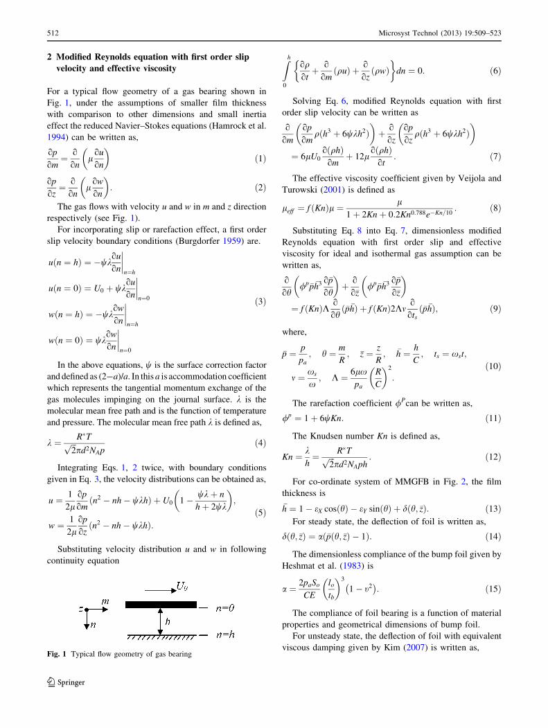
2 Modified Reynolds equation with first order slip
velocity and effective viscosity
For a typical flow geometry of a gas bearing shown in
Fig. 1, under the assumptions of smaller film thickness
with comparison to other dimensions and small inertia
effect the reduced Navier–Stokes equations (Hamrock et al.
1994) can be written as,
op
om¼ o
onl
ou
on
� �ð1Þ
op
oz¼ o
onl
ow
on
� �: ð2Þ
The gas flows with velocity u and w in m and z direction
respectively (see Fig. 1).
For incorporating slip or rarefaction effect, a first order
slip velocity boundary conditions (Burgdorfer 1959) are.
uðn ¼ hÞ ¼ �wkou
on
����n¼h
uðn ¼ 0Þ ¼ U0 þ wkou
on
����n¼0
wðn ¼ hÞ ¼ �wkow
on
����n¼h
wðn ¼ 0Þ ¼ wkow
on
����n¼0
ð3Þ
In the above equations, w is the surface correction factor
and defined as (2-a)/a. In this a is accommodation coefficient
which represents the tangential momentum exchange of the
gas molecules impinging on the journal surface. k is the
molecular mean free path and is the function of temperature
and pressure. The molecular mean free path k is defined as,
k ¼ R�Tffiffiffi2p
pd2NApð4Þ
Integrating Eqs. 1, 2 twice, with boundary conditions
given in Eq. 3, the velocity distributions can be obtained as,
u ¼ 1
2lop
omðn2 � nh� wkhÞ þ U0 1� wkþ n
hþ 2wk
� �;
w ¼ 1
2lop
ozðn2 � nh� wkhÞ:
ð5Þ
Substituting velocity distribution u and w in following
continuity equation
Zh
0
oqotþ o
omðquÞ þ o
ozðqwÞ
� �dn ¼ 0: ð6Þ
Solving Eq. 6, modified Reynolds equation with first
order slip velocity can be written as
o
om
op
omqðh3 þ 6wkh2Þ
� �þ o
oz
op
ozqðh3 þ 6wkh2Þ
� �
¼ 6lU0
oðqhÞomþ 12l
oðqhÞot
: ð7Þ
The effective viscosity coefficient given by Veijola and
Turowski (2001) is defined as
leff ¼ f ðKnÞl ¼ l
1þ 2Knþ 0:2Kn0:788e�Kn=10: ð8Þ
Substituting Eq. 8 into Eq. 7, dimensionless modified
Reynolds equation with first order slip and effective
viscosity for ideal and isothermal gas assumption can be
written as,
o
oh/p�p�h3 o�p
oh
� �þ o
o�z/p�p�h3 o�p
o�z
� �
¼ f ðKnÞK o
ohð�p�hÞ þ f ðKnÞ2Km
o
otsð�p�hÞ; ð9Þ
where,
�p ¼ p
pa; h ¼ m
R; �z ¼ z
R; �h ¼ h
C; ts ¼ xst;
m ¼ xs
x; K ¼ 6lx
pa
R
C
� �2
:
ð10Þ
The rarefaction coefficient /Pcan be written as,
/p ¼ 1þ 6wKn: ð11Þ
The Knudsen number Kn is defined as,
Kn ¼ kh¼ R�Tffiffiffi
2p
pd2NAph: ð12Þ
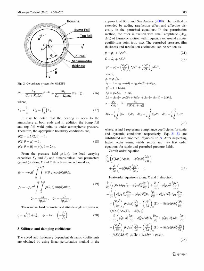
For co-ordinate system of MMGFB in Fig. 2, the film
thickness is
�h ¼ 1� eX cosðhÞ � eY sinðhÞ þ dðh; �zÞ: ð13ÞFor steady state, the deflection of foil is written as,
dðh; �zÞ ¼ a �pðh; �zÞ � 1ð Þ: ð14Þ
The dimensionless compliance of the bump foil given by
Heshmat et al. (1983) is
a ¼ 2paSo
CE
lotb
� �3
1� t2�
: ð15Þ
The compliance of foil bearing is a function of material
properties and geometrical dimensions of bump foil.
For unsteady state, the deflection of foil with equivalent
viscous damping given by Kim (2007) is written as,Fig. 1 Typical flow geometry of gas bearing
512 Microsyst Technol (2013) 19:509–523
123
dts ¼ CB
CB þ KBDtsdts�Dts þ Dts
CB þ KBDts�ptsðh; �zÞ; ð16Þ
where,
KB ¼1
a; CB ¼
gm
�KB: ð17Þ
It may be noted that the bearing is open to the
atmosphere at both ends and in addition the bump foil
and top foil weld point is under atmospheric pressure.
Therefore, the appropriate boundary conditions are,
�pð�z ¼ �L=2; hÞ ¼ 1;
�pð�z; h ¼ pÞ ¼ 1;
�pð�z; h ¼ 0Þ ¼ �pð�z; h ¼ 2pÞ:ð18Þ
From the pressure field �pðh; zÞ, the load carrying
capacities FX and FY and dimensionless load parameters
fX and fY along X and Y directions are obtained as,
fX ¼ �paR2
Z2p
0
ZL=R
0
�pðh; zÞ cosðhÞdhdz;
fY ¼ �paR2
Z2p
0
ZL=R
0
�pðh; zÞ sinðhÞdhdz;
fX ¼fX
2paRL; fY ¼
fY
2paRL:
ð19Þ
The resultant load parameter and attitude angle are given as,
f ¼ffiffiffiffiffiffiffiffiffiffiffiffiffiffiffif2
X þ f2Y
q; / ¼ tan�1 � fY
fX
� �: ð20Þ
3 Stiffness and damping coefficients
The speed and frequency dependent dynamic coefficients
are obtained by using linear perturbation method in the
approach of Kim and San Andres (2008). The method is
extended by adding rarefaction effect and effective vis-
cosity in the perturbed equations. In the perturbation
method, the rotor is excited with small amplitude (DeX,
DeY) of harmonic motion with frequency xs around a static
equilibrium point (eX0, eY0). The perturbed pressure, film
thickness and rarefaction coefficient can be written as,
�p ¼ �p0 þ D�peits ; ð21Þ�h ¼ �h0 þ D�heits ; ð22Þ
/p ¼ /p0 þ
o/p
o�p
� �0
D�peits þ o/p
o�h
� �0
D�heits ;
where;
�p0 ¼ p0=pa;
�h0 ¼ 1� eX0 cosðhÞ � eY0 sinðhÞ þ d�p0a;
/p0 ¼ 1þ 6aKn;
D�p ¼ �pXDeX þ �pYDeY ;
D�h ¼ DeX½� cosðhÞ þ �ad�pX� þ DeY ½� sinðhÞ þ �ad�pY �;
a ¼ pa
CKf; �a ¼ pa
C½Kf ð1þ igÞ� ;
d�p0 ¼1
L
ZL
0
ð�p0 � 1Þdz; d�pX ¼1
L
ZL
0
�pXdz; d�pY ¼1
L
ZL
0
�pY dz;
ð23Þ
where, a and �a represents compliance coefficients for static
and dynamic conditions respectively. Eqs. 21–23 are
substituted into modified Reynolds Eq. 9. After neglecting
higher order terms, yields zeroth and two first order
equations for static and perturbed pressure fields.
Zeroth-order equation,
o
ohf ðKn0ÞK�p0
�h0 � /p0 �p0
�h30
o�p0
oh
� �
þ o
o�z�/p
0�p0�h3
0
o�p0
o�z
� �¼ 0: ð24Þ
First-order equations along X and Y direction,
o
ohf Knð ÞK�pC
�h0 � /p0�p0
�h30
o�pC
oh
� �þ o
o�z�/p
0 �p0�h3
0
o�pC
o�z
� �
¼ o
oh/p
0�pC�h3
0
o�p0
oh� /p
0�p03�h20PC
o�p0
ohþ /p
0�p03�h20�ad�pC
o�p0
oh
�
þ o/P
o�p
� �0
�pC�p0�h3
0
o�p0
oh� o/P
o�h
� �0
PC � �ad�pCð Þ�p0�h3
0
o�p0
oh
þf Knð ÞK�p0 PC � �ad�pCð ÞÞ
þ o
o�z/p
0�pC�h3
0
o�p0
o�z� /p
0�p03�h20PC
o�p0
o�zþ /p
0�p03�h20�ad�pC
o�p0
o�z
�
þ o/P
o�p
� �0
�pC�p0�h3
0
o�p0
o�z� o/P
o�h
� �0
PC � �ad�pCð Þ�p0�h3
0
o�p0
o�z
�
� f Knð Þ2Kmi ��p0PC þ �p0�ad�pC þ �pC�h0ð Þ;
ð25Þ
Fig. 2 Co-ordinate system for MMGFB
Microsyst Technol (2013) 19:509–523 513
123

Where, C ¼ X; Y and PX ¼ cos h; PY ¼ sin h:For solving Eqs. 24–25, the boundary conditions are,
�pð�z; h ¼ 0Þ ¼ �pð�z; h ¼ 2pÞ;�pð�z ¼ �L=2; hÞ ¼ 1;
�pð�z; h ¼ pÞ ¼ 1;
�pXð�z ¼ �L=2; hÞ ¼ �pYð�z ¼ �L=2; hÞ ¼ 0;
�pXð�z; h ¼ pÞ ¼ �pYð�z; h ¼ pÞ ¼ 0:
ð26Þ
For a given rotating speed N and eccentricity ratio e,zeroth order equation is solved and pressure �p0 and film
thickness �h0 are obtained. Substituting �p0 and �h0 in first
order Eq. 25, the perturbed pressure �pX and�pY are obtained.
Both zeroth order and first order perturbed equations are
solved by using control volume formulation (CVF)
discussed in Sect. 6. The perturbed pressure �pX and �pY
are in complex number form and comprises real and
imaginary parts. The stiffness and damping coefficients are
determined by integrating perturbed pressures �pX and �pY
over bearing surface as follows,
where, WC
KXX KXY
KYX KYY
� ¼ kxx kxy
kyx kyy
� ;
where, WCxs
CXX CXY
CYX CYY
� ¼ cxx cxy
cyx cyy
� :
4 Modal analysis of rotor bearing system
The eigenvalue problem for rotor supported on foil bear-
ings is formulated similar to the approach of Pan and Kim
(2006). The stiffness and damping coefficients obtained by
perturbation method in previous section are used in the
modal analysis. The natural frequencies are predicted for
three different models viz. no- slip, slip without leff and
slip with leff.
For a Jeffcott rotor having two degrees of freedom and
with no external force, the equations of motion in matrix
form can be written as,
mr 0
0 mr
� D €XD €Y
� �þ BXX BXY
BYX BYY
� DXDY
� �¼ 0
0
� �ð29Þ
where, BIJ ¼ kIJ þ jcIJxs is impedance of foil bearing in
which stiffness and damping coefficients varies with
excitation frequency.
With assumption of nonzero eigen modes fDXm
DYmgTG¼bacward=forward , BG ¼ �mrk and k ¼ ða� jxsÞ2, a
eigenvalue problem can be written as,
BXX � BG BXY
BYX BYY � BG
� DXm
DYm
� �G¼backward=forward
¼ 0
0
� �: ð30Þ
After solving Eq. 30, modal impedance for different
modes can be written as,
BG¼backward=forward ¼BXX þ BYY
2
�
ffiffiffiffiffiffiffiffiffiffiffiffiffiffiffiffiffiffiffiffiffiffiffiffiffiffiffiffiffiffiffiffiffiffiffiffiffiffiffiffiffiffiffiffiffiffiffiffiBXX � BYY
2
� �2
þBXYBYX
s: ð31Þ
The modal impedance is a complex number; the real and
imaginary part represents modal stiffness and modal damping
respectively. When modal damping becomes zero, the
corresponding excitation frequency ratio and modal
stiffness is called as meigen and critical modal stiffness
respectively. Thus from Eq. 31, it can be written as,
mrx2s eigen ¼ ks modal: ð32Þ
For a given speed x and rotor mass mr, the modal
impedances for different values of excitation frequency
ratio m are obtained from Eq. 31 and plotted as shown in
kxx kxy
kyx kyy
� ¼ � WR
2CL
Z 2p
0
Z L=R
0
Reð�pXÞ cosðhÞ Reð�pYÞ cosðhÞReð�pXÞ sinðhÞ Reð�pYÞ sinðhÞ
� dhdz; ð27Þ
cxx cxy
cyx cyy
� ¼ � WR
2CLxs
Z 2p
0
Z L=R
0
Imð�pXÞ cosðhÞ Imð�pYÞ cosðhÞImð�pXÞ sinðhÞ Imð�pYÞ sinðhÞ
� dhdz; ð28Þ
514 Microsyst Technol (2013) 19:509–523
123
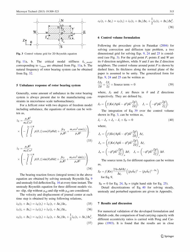
Fig. 11a, b. The critical modal stiffness ks modal
corresponding to meigen are obtained from Fig. 11a, b. The
natural frequency of rotor bearing system can be obtained
from Eq. 32.
5 Unbalance response of rotor bearing system
Generally, some amount of unbalance in the rotor bearing
system is always present due to the manufacturing con-
straints in micro/meso scale turbomachinery.
For a Jeffcott rotor with two degrees of freedom model
including unbalance, the equations of motion can be writ-
ten as,
€eX ¼paR2
mrCx2
� �Z2p
0
ZL=R
0
�pðh; �zÞ cosðhÞdhd�zþ feX
paR2þ mrex2 cosðtsÞ
paR2
0B@
1CA;
ð33Þ
€eY ¼paR2
mrCx2
� �Z2p
0
ZL=R
0
�pðh; �zÞ sinðhÞdhd�zþ feY
paR2þ mrex2 sinðtsÞ
paR2
0B@
1CA:
ð34Þ
The bearing reaction forces (integral terms) in the above
equation are obtained by solving unsteady Reynolds Eq. 9
and unsteady foil deflection Eq. 16 at every time instant. The
unsteady Reynolds equation for three different models viz.
no- slip, slip without leff and slip with leff are considered.
The velocity and displacement of journal center at each
time step is obtained by using following relations,
_eXðts þ DtsÞ ¼ _eXðtsÞ þ €eXðts þ DtsÞDts; ð35Þ_eYðts þ DtsÞ ¼ _eYðtsÞ þ €eYðts þ DtsÞDts; ð36Þ
eXðts þ DtsÞ ¼ eXðtsÞ þ _eXðts þ DtsÞDts þ1
2€eXðts þ DtsÞDt2
s ;
ð37Þ
eYðts þ DtsÞ ¼ eYðtsÞ þ _eYðts þ DtsÞDts þ1
2€eYðts þ DtsÞDt2
s :
ð38Þ
6 Control volume formulation
Following the procedure given in Patankar (2004) for
solving convection and diffusion type problem, a two
dimensional grid for solving Eqs. 9, 24 and 25 is consid-
ered (see Fig. 3). For the grid point P, points E and W are
its h direction neighbors, while N and S are the Z direction
neighbors. The control volume around point P is shown by
dashed lines. Its thickness along the normal plane of the
paper is assumed to be unity. The generalized form for
Eqs. 9, 24 and 25 can be written as
oJh
ohþ oJz
o�zþ Source term ¼ 0 ð39Þ
where, Jh and Jz are fluxes in h and Z directions
respectively. They are defined by,
Jh ¼ f ðKnÞK�p�h� /p�p�h3 o�p
oh
� �; Jz ¼ �/p�p�h3 o�p
o�z
� �:
The integration of Eq. 39 over the control volume
shown in Fig. 3, can be written as,
Je � Jw þ Jn � Js þ SP ¼ 0 ð40Þ
where,
Je ¼ f ðKnÞK�p�h� /p�p�h3 o�p
oh
� �e
D�z;
Jw ¼ f ðKnÞK�p�h� /p�p�h3 o�p
oh
� �w
D�z;
Jn ¼ �/p�p�h3 o�p
o�z
� �n
Dh; Js ¼ �/p�p�h3 o�p
o�z
� �s
Dh:
The source term SP for different equation can be written
as,
SP ¼ f ðKnÞ 2KmDhD�z
Dtsð�pP
�hPÞts � ð�pP�hPÞts�Dts
�for Eq: 9;
SP = 0 for Eq. 24, SP = (right hand side for Eq. 25).
Detail discretizations of Eq. 40 for solving steady,
unsteady and perturbed equations are given in Appendix.
7 Results and discussion
For numerical validation of the developed formulation and
Matlab code, the comparison of load carrying capacity with
different eccentricity ratios is carried with Peng and Car-
pino (1993). It is found that the results are in close
Fig. 3 Control volume grid for 2D Reynolds equation
Microsyst Technol (2013) 19:509–523 515
123
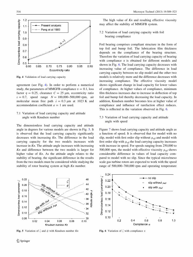
agreement (see Fig. 4). In order to perform a numerical
study, the parameters of MMGFB compliance a = 0.1, loss
factor g = 0.25, clearance C = 25 lm, eccentricity ratio
e = 0.7, speed range N = 100,000–500,000 rpm, air
molecular mean free path k = 0.3 lm at 1023 K and
accommodation coefficient a = 1 are used.
7.1 Variation of load carrying capacity and attitude
angle with Knudsen number
The dimensionless load carrying capacity and attitude
angle in degrees for various models are shown in Fig. 5. It
is observed that the load carrying capacity significantly
decreases with increasing Kn. The difference in the load
carrying capacity for the two models increases with
increase in Kn. The attitude angle increases with increasing
Kn and difference between the two models is larger for
higher value of Kn. As the attitude angle relates to the
stability of bearing, the significant difference in the results
from the two models must be considered while studying the
stability of rotor bearing system at high Kn number.
The high value of Kn and resulting effective viscosity
may affect the stability of MMGFB system.
7.2 Variation of load carrying capacity with foil
bearing compliance
Foil bearing comprises compliant structure in the form of
top foil and bump foil. The lubrication film thickness
depends on the compliance of the bearing structure.
Therefore the variation of load carrying capacity of bearing
with compliance a is obtained for different models and
shown in Fig. 6. The load carrying capacity decreases with
increasing value of compliance. The difference in load
carrying capacity between no slip model and the other two
models is relatively more and the difference decreases with
increasing compliance. The effective viscosity model
shows significant change in load capacity for lower values
of compliance. At higher values of compliance, minimum
film thickness increases due to increase in deflection of top
foil and bump foil thereby decreasing the load capacity. In
addition, Knudsen number becomes less at higher value of
compliance and influence of rarefaction effect reduces.
This is reflected in the variation observed in Fig. 6.
7.3 Variation of load carrying capacity and attitude
angle with speed
Figure 7 shows load carrying capacity and attitude angle as
a function of speed. It is observed that for model with no
slip, model with first order slip without leff and model with
first order slip with leff the load carrying capacity increases
with increase in speed. For speeds ranging from 250,000 to
500,000 rpm, the model with effective viscosity leff shows
considerable difference in values of load capacity com-
pared to model with no slip. Since the typical micro/meso
scale gas turbine rotors are expected to work with the speed
range of 500,000–700,000 rpm and operating temperature
Fig. 4 Validation of load carrying capacity
Fig. 5 Variation of f and / with Knudsen number Kn Fig. 6 Variation of f with compliance a
516 Microsyst Technol (2013) 19:509–523
123
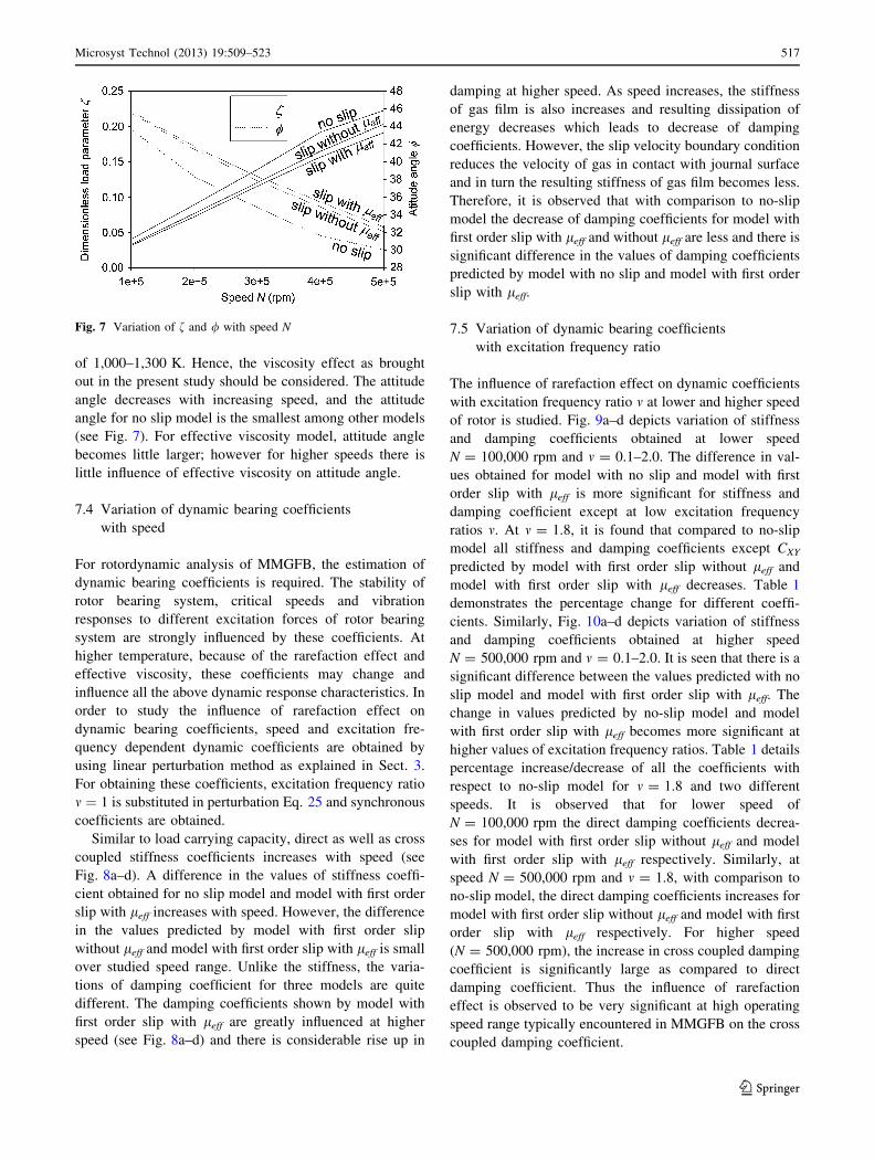
of 1,000–1,300 K. Hence, the viscosity effect as brought
out in the present study should be considered. The attitude
angle decreases with increasing speed, and the attitude
angle for no slip model is the smallest among other models
(see Fig. 7). For effective viscosity model, attitude angle
becomes little larger; however for higher speeds there is
little influence of effective viscosity on attitude angle.
7.4 Variation of dynamic bearing coefficients
with speed
For rotordynamic analysis of MMGFB, the estimation of
dynamic bearing coefficients is required. The stability of
rotor bearing system, critical speeds and vibration
responses to different excitation forces of rotor bearing
system are strongly influenced by these coefficients. At
higher temperature, because of the rarefaction effect and
effective viscosity, these coefficients may change and
influence all the above dynamic response characteristics. In
order to study the influence of rarefaction effect on
dynamic bearing coefficients, speed and excitation fre-
quency dependent dynamic coefficients are obtained by
using linear perturbation method as explained in Sect. 3.
For obtaining these coefficients, excitation frequency ratio
m ¼ 1 is substituted in perturbation Eq. 25 and synchronous
coefficients are obtained.
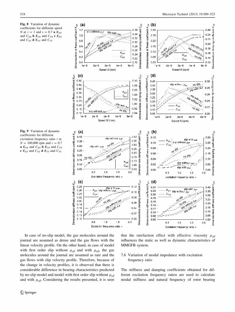
Similar to load carrying capacity, direct as well as cross
coupled stiffness coefficients increases with speed (see
Fig. 8a–d). A difference in the values of stiffness coeffi-
cient obtained for no slip model and model with first order
slip with leff increases with speed. However, the difference
in the values predicted by model with first order slip
without leff and model with first order slip with leff is small
over studied speed range. Unlike the stiffness, the varia-
tions of damping coefficient for three models are quite
different. The damping coefficients shown by model with
first order slip with leff are greatly influenced at higher
speed (see Fig. 8a–d) and there is considerable rise up in
damping at higher speed. As speed increases, the stiffness
of gas film is also increases and resulting dissipation of
energy decreases which leads to decrease of damping
coefficients. However, the slip velocity boundary condition
reduces the velocity of gas in contact with journal surface
and in turn the resulting stiffness of gas film becomes less.
Therefore, it is observed that with comparison to no-slip
model the decrease of damping coefficients for model with
first order slip with leff and without leff are less and there is
significant difference in the values of damping coefficients
predicted by model with no slip and model with first order
slip with leff.
7.5 Variation of dynamic bearing coefficients
with excitation frequency ratio
The influence of rarefaction effect on dynamic coefficients
with excitation frequency ratio m at lower and higher speed
of rotor is studied. Fig. 9a–d depicts variation of stiffness
and damping coefficients obtained at lower speed
N = 100,000 rpm and m = 0.1–2.0. The difference in val-
ues obtained for model with no slip and model with first
order slip with leff is more significant for stiffness and
damping coefficient except at low excitation frequency
ratios m. At m = 1.8, it is found that compared to no-slip
model all stiffness and damping coefficients except CXY
predicted by model with first order slip without leff and
model with first order slip with leff decreases. Table 1
demonstrates the percentage change for different coeffi-
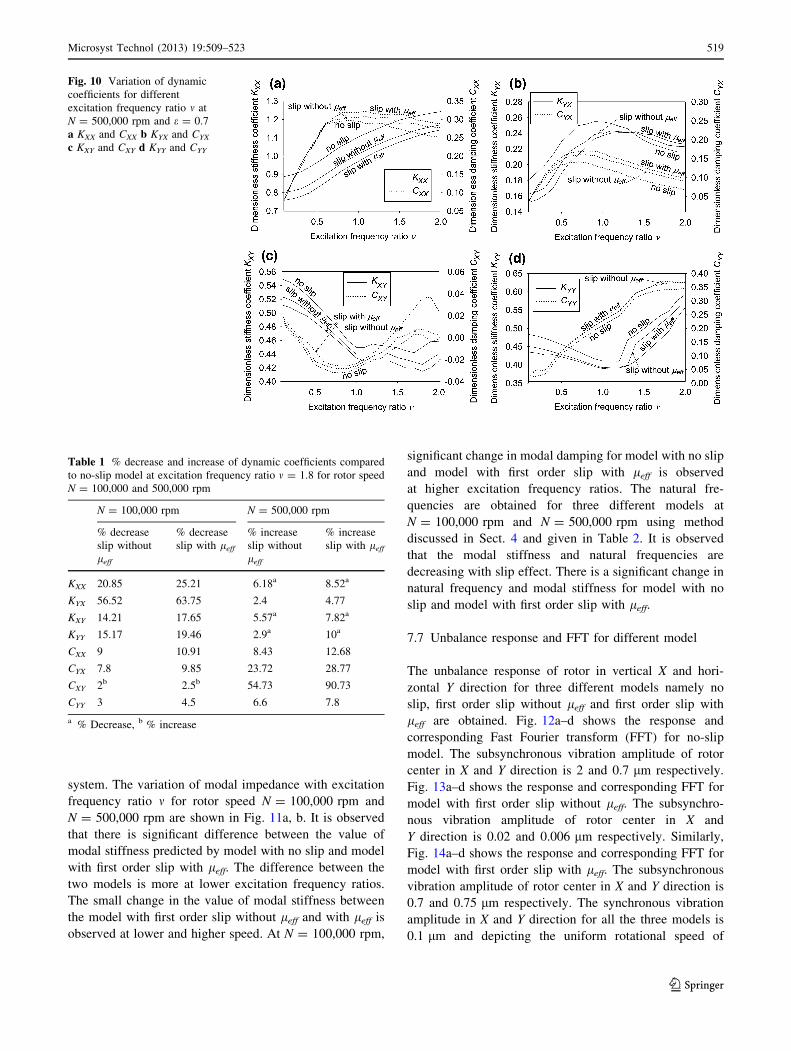
cients. Similarly, Fig. 10a–d depicts variation of stiffness
and damping coefficients obtained at higher speed
N = 500,000 rpm and m = 0.1–2.0. It is seen that there is a
significant difference between the values predicted with no
slip model and model with first order slip with leff. The
change in values predicted by no-slip model and model
with first order slip with leff becomes more significant at
higher values of excitation frequency ratios. Table 1 details
percentage increase/decrease of all the coefficients with
respect to no-slip model for m = 1.8 and two different
speeds. It is observed that for lower speed of
N = 100,000 rpm the direct damping coefficients decrea-
ses for model with first order slip without leff and model
with first order slip with leff respectively. Similarly, at
speed N = 500,000 rpm and m = 1.8, with comparison to
no-slip model, the direct damping coefficients increases for
model with first order slip without leff and model with first
order slip with leff respectively. For higher speed
(N = 500,000 rpm), the increase in cross coupled damping
coefficient is significantly large as compared to direct
damping coefficient. Thus the influence of rarefaction
effect is observed to be very significant at high operating
speed range typically encountered in MMGFB on the cross
coupled damping coefficient.
Fig. 7 Variation of f and / with speed N
Microsyst Technol (2013) 19:509–523 517
123
In case of no-slip model, the gas molecules around the
journal are assumed as dense and the gas flows with the
linear velocity profile. On the other hand, in case of model
with first order slip without leff and with leff, the gas
molecules around the journal are assumed as rare and the
gas flows with slip velocity profile. Therefore, because of
the change in velocity profiles, it is observed that there is
considerable difference in bearing characteristics predicted
by no-slip model and model with first order slip without leff
and with leff. Considering the results presented, it is seen
that the rarefaction effect with effective viscosity leff
influences the static as well as dynamic characteristics of
MMGFB system.
7.6 Variation of modal impedance with excitation
frequency ratio
The stiffness and damping coefficients obtained for dif-
ferent excitation frequency ratios are used to calculate
modal stiffness and natural frequency of rotor bearing
Fig. 8 Variation of dynamic
coefficients for different speed
N at m = 1 and e = 0.7 a KXX
and CXX b KYX and CYX c KXY
and CXY d KYY and CYY
Fig. 9 Variation of dynamic
coefficients for different
excitation frequency ratio m at
N = 100,000 rpm and e = 0.7
a KXX and CXX b KYX and CYX
c KXY and CXY d KYY and CYY
518 Microsyst Technol (2013) 19:509–523
123
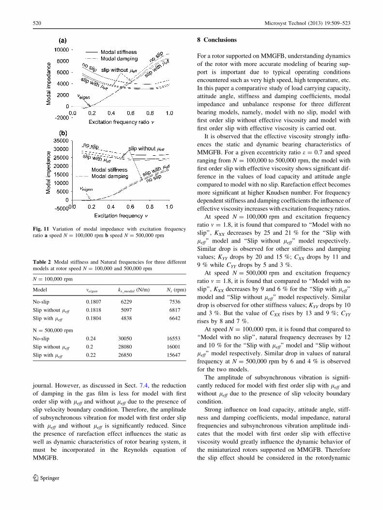
system. The variation of modal impedance with excitation
frequency ratio m for rotor speed N = 100,000 rpm and
N = 500,000 rpm are shown in Fig. 11a, b. It is observed
that there is significant difference between the value of
modal stiffness predicted by model with no slip and model
with first order slip with leff. The difference between the
two models is more at lower excitation frequency ratios.
The small change in the value of modal stiffness between
the model with first order slip without leff and with leff is
observed at lower and higher speed. At N = 100,000 rpm,
significant change in modal damping for model with no slip
and model with first order slip with leff is observed
at higher excitation frequency ratios. The natural fre-
quencies are obtained for three different models at
N = 100,000 rpm and N = 500,000 rpm using method
discussed in Sect. 4 and given in Table 2. It is observed
that the modal stiffness and natural frequencies are
decreasing with slip effect. There is a significant change in
natural frequency and modal stiffness for model with no
slip and model with first order slip with leff.
7.7 Unbalance response and FFT for different model
The unbalance response of rotor in vertical X and hori-
zontal Y direction for three different models namely no
slip, first order slip without leff and first order slip with
leff are obtained. Fig. 12a–d shows the response and
corresponding Fast Fourier transform (FFT) for no-slip
model. The subsynchronous vibration amplitude of rotor
center in X and Y direction is 2 and 0.7 lm respectively.
Fig. 13a–d shows the response and corresponding FFT for
model with first order slip without leff. The subsynchro-
nous vibration amplitude of rotor center in X and
Y direction is 0.02 and 0.006 lm respectively. Similarly,
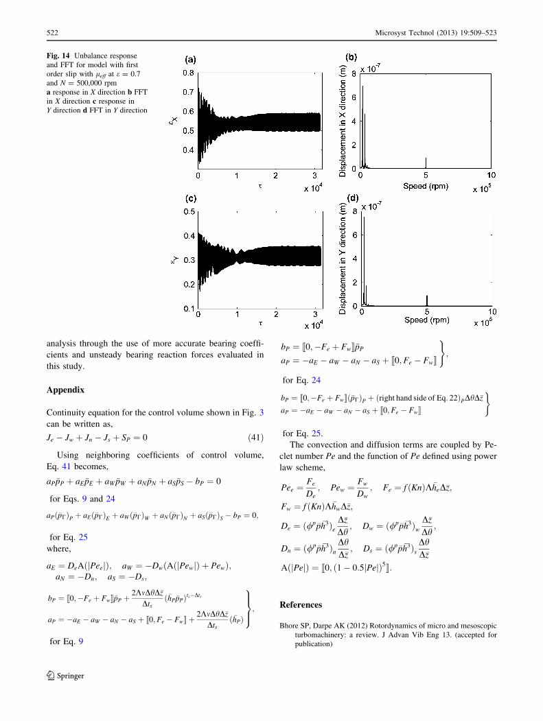
Fig. 14a–d shows the response and corresponding FFT for
model with first order slip with leff. The subsynchronous
vibration amplitude of rotor center in X and Y direction is
0.7 and 0.75 lm respectively. The synchronous vibration
amplitude in X and Y direction for all the three models is
0.1 lm and depicting the uniform rotational speed of
Fig. 10 Variation of dynamic
coefficients for different
excitation frequency ratio m at
N = 500,000 rpm and e = 0.7
a KXX and CXX b KYX and CYX
c KXY and CXY d KYY and CYY
Table 1 % decrease and increase of dynamic coefficients compared
to no-slip model at excitation frequency ratio m = 1.8 for rotor speed
N = 100,000 and 500,000 rpm
N = 100,000 rpm N = 500,000 rpm
% decrease
slip without
leff
% decrease
slip with leff
% increase
slip without
leff
% increase
slip with leff
KXX 20.85 25.21 6.18a 8.52a
KYX 56.52 63.75 2.4 4.77
KXY 14.21 17.65 5.57a 7.82a
KYY 15.17 19.46 2.9a 10a
CXX 9 10.91 8.43 12.68
CYX 7.8 9.85 23.72 28.77
CXY 2b 2.5b 54.73 90.73
CYY 3 4.5 6.6 7.8
a % Decrease, b % increase
Microsyst Technol (2013) 19:509–523 519
123
journal. However, as discussed in Sect. 7.4, the reduction
of damping in the gas film is less for model with first
order slip with leff and without leff due to the presence of
slip velocity boundary condition. Therefore, the amplitude
of subsynchronous vibration for model with first order slip
with leff and without leff is significantly reduced. Since
the presence of rarefaction effect influences the static as
well as dynamic characteristics of rotor bearing system, it
must be incorporated in the Reynolds equation of
MMGFB.
8 Conclusions
For a rotor supported on MMGFB, understanding dynamics
of the rotor with more accurate modeling of bearing sup-
port is important due to typical operating conditions
encountered such as very high speed, high temperature, etc.
In this paper a comparative study of load carrying capacity,
attitude angle, stiffness and damping coefficients, modal
impedance and unbalance response for three different
bearing models, namely, model with no slip, model with
first order slip without effective viscosity and model with
first order slip with effective viscosity is carried out.
It is observed that the effective viscosity strongly influ-
ences the static and dynamic bearing characteristics of
MMGFB. For a given eccentricity ratio e = 0.7 and speed
ranging from N = 100,000 to 500,000 rpm, the model with
first order slip with effective viscosity shows significant dif-
ference in the values of load capacity and attitude angle
compared to model with no slip. Rarefaction effect becomes
more significant at higher Knudsen number. For frequency
dependent stiffness and damping coefficients the influence of
effective viscosity increases with excitation frequency ratios.
At speed N = 100,000 rpm and excitation frequency
ratio m = 1.8, it is found that compared to ‘‘Model with no
slip’’, KXX decreases by 25 and 21 % for the ‘‘Slip with
leff’’ model and ‘‘Slip without leff’’ model respectively.
Similar drop is observed for other stiffness and damping
values; KYY drops by 20 and 15 %; CXX drops by 11 and
9 % while CYY drops by 5 and 3 %.
At speed N = 500,000 rpm and excitation frequency
ratio m = 1.8, it is found that compared to ‘‘Model with no
slip’’, KXX decreases by 9 and 6 % for the ‘‘Slip with leff’’
model and ‘‘Slip without leff’’ model respectively. Similar
drop is observed for other stiffness values; KYY drops by 10
and 3 %. But the value of CXX rises by 13 and 9 %; CYY
rises by 8 and 7 %.
At speed N = 100,000 rpm, it is found that compared to
‘‘Model with no slip’’, natural frequency decreases by 12
and 10 % for the ‘‘Slip with leff’’ model and ‘‘Slip without
leff’’ model respectively. Similar drop in values of natural
frequency at N = 500,000 rpm by 6 and 4 % is observed
for the two models.
The amplitude of subsynchronous vibration is signifi-
cantly reduced for model with first order slip with leff and
without leff due to the presence of slip velocity boundary
condition.
Strong influence on load capacity, attitude angle, stiff-
ness and damping coefficients, modal impedance, natural
frequencies and subsynchronous vibration amplitude indi-
cates that the model with first order slip with effective
viscosity would greatly influence the dynamic behavior of
the miniaturized rotors supported on MMGFB. Therefore
the slip effect should be considered in the rotordynamic
Fig. 11 Variation of modal impedance with excitation frequency
ratio a speed N = 100,000 rpm b speed N = 500,000 rpm
Table 2 Modal stiffness and Natural frequencies for three different
models at rotor speed N = 100,000 and 500,000 rpm
N = 100,000 rpm
Model meigen ks_modal (N/m) Ns (rpm)
No-slip 0.1807 6229 7536
Slip without leff 0.1818 5097 6817
Slip with leff 0.1804 4838 6642
N = 500,000 rpm
No-slip 0.24 30050 16553
Slip without leff 0.2 28080 16001
Slip with leff 0.22 26850 15647
520 Microsyst Technol (2013) 19:509–523
123
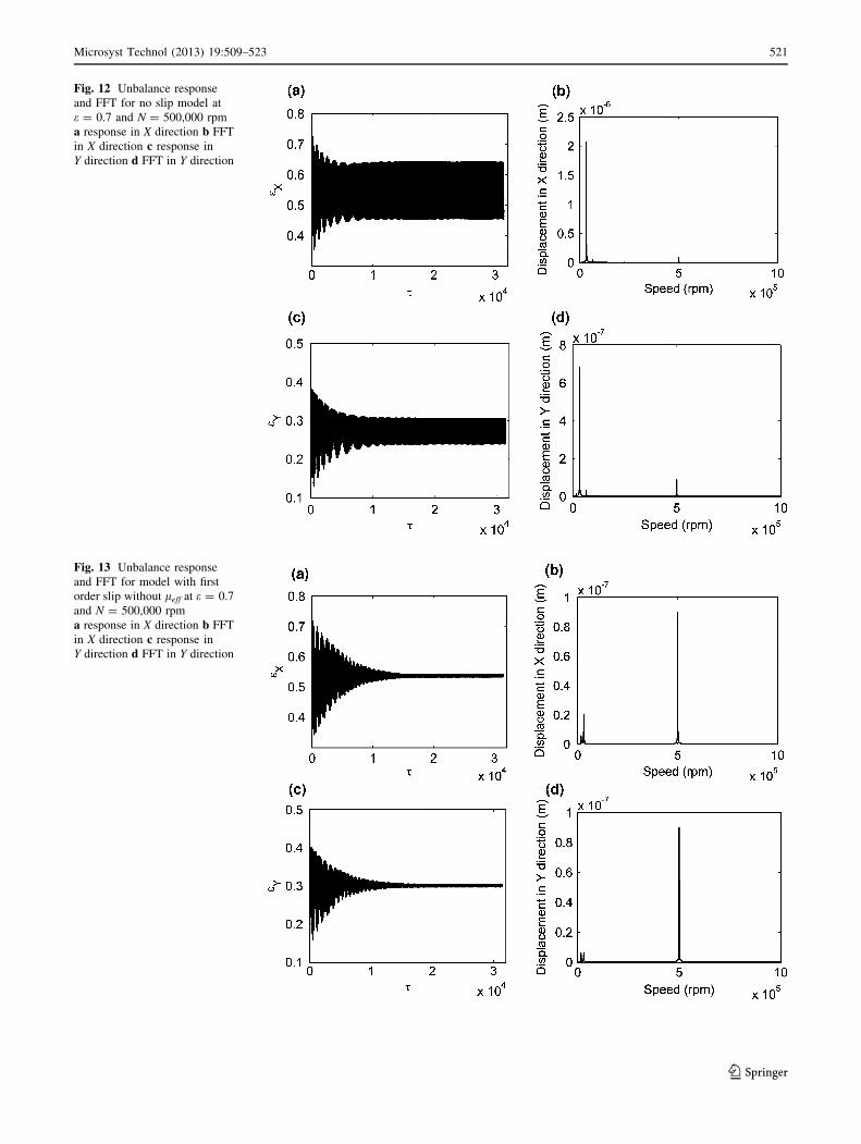
Fig. 12 Unbalance response
and FFT for no slip model at
e = 0.7 and N = 500,000 rpm
a response in X direction b FFT
in X direction c response in
Y direction d FFT in Y direction
Fig. 13 Unbalance response
and FFT for model with first
order slip without leff at e = 0.7
and N = 500,000 rpm
a response in X direction b FFT
in X direction c response in
Y direction d FFT in Y direction
Microsyst Technol (2013) 19:509–523 521
123
analysis through the use of more accurate bearing coeffi-
cients and unsteady bearing reaction forces evaluated in
this study.
Appendix
Continuity equation for the control volume shown in Fig. 3
can be written as,
Je � Jw þ Jn � Js þ SP ¼ 0 ð41Þ
Using neighboring coefficients of control volume,
Eq. 41 becomes,
aP�pP þ aE �pE þ aW �pW þ aN �pN þ aS�pS � bP ¼ 0
for Eqs. 9 and 24
aPð�pCÞP þ aEð�pCÞE þ aWð�pCÞW þ aNð�pCÞN þ aSð�pCÞS � bP ¼ 0;
for Eq. 25
where,
aE ¼ DeAðjPeejÞ; aW ¼ �DwðAðjPewjÞ þ PewÞ;aN ¼ �Dn; aS ¼ �Ds;
bP ¼ ½½0;�Fe þ Fw���pP þ2KmDhD�z
Dtsð�hP�pPÞts�Dts
aP ¼ �aE � aW � aN � aS þ ½½0;Fe � Fw�� þ2KmDhD�z
Dtsð�hPÞ
9>>=>>;;
for Eq. 9
bP ¼ ½½0;�Fe þ Fw���pP
aP ¼ �aE � aW � aN � aS þ ½½0;Fe � Fw��
);
for Eq. 24
bP ¼ ½½0;�Fe þ Fw��ð�pCÞP þ ðright hand side of Eq: 22ÞPDhD�z
aP ¼ �aE � aW � aN � aS þ ½½0;Fe � Fw��
)
for Eq. 25.
The convection and diffusion terms are coupled by Pe-
clet number Pe and the function of Pe defined using power
law scheme,
Pee ¼Fe
De; Pew ¼
Fw
Dw; Fe ¼ f ðKnÞK�heD�z;
Fw ¼ f ðKnÞK�hwD�z;
De ¼ ð/p�p�h3ÞeD�z
Dh; Dw ¼ ð/p�p�h3Þw
D�z
Dh;
Dn ¼ ð/p�p�h3ÞnDhD�z; Ds ¼ ð/p�p�h3Þs
DhD�z
AðjPejÞ ¼ ½½0; ð1� 0:5jPejÞ5��:
References
Bhore SP, Darpe AK (2012) Rotordynamics of micro and mesoscopic
turbomachinery: a review. J Advan Vib Eng 13. (accepted for
publication)
Fig. 14 Unbalance response
and FFT for model with first
order slip with leff at e = 0.7
and N = 500,000 rpm
a response in X direction b FFT
in X direction c response in
Y direction d FFT in Y direction
522 Microsyst Technol (2013) 19:509–523
123
Breuer K (2001) Lubrication in MEMS: handbook on MEMS. CRC
Press, Florida
Burgdorfer A (1959) The influence of the molecular mean free path
on the performance of hydrodynamic gas lubricated bearings.
ASME J Basic Eng 81(1):94–100
Chan W, Sun Y (2003) Analytical modeling of ultra-thin film
bearings. IEEE J Micromech Microeng 13:463–473
Dellacorte C (1997) A new foil gas bearings test rig for use of 700oC
and 70,000 rpm. OH: NASA TM-107405, Cleveland
Epstein AH (2003) Millimeter scale MEMS gas turbine engines. In:
Proceedings of ASME Turbo Expo, Power for Land, Sea and
Air, Atlanta, Georgia, USA
Fukui S, Kaneko R (1988) Analysis of ultra-thin gas film lubrication
based on linearized Boltzmann equation: first report-derivation
of generalized lubrication equation including thermal creep flow.
ASME J Tribol 110:253–262
Gad-el-Hak (2001) The MEMS handbook. CRC Press, Florida
Hamrock BJ, Schmid SR, Jacobson BO (1994) Fundamentals of fluid
film lubrication. Marcel Dekker Inc., New York
Heshmat H, Walowit JA, Pinkus O (1983) Analysis of gas lubricated
foil journal bearings. ASME J Lubr Technol 105:647–655
Isomura K, Tanaka S, Togo S-I, Esashi M (2005) Development of
high-speed micro-gas bearings for three-dimensional micro-
turbo machines. IOP J Micromech Microeng 15:S222–S227
Isomura K, Murayama M, Teramoto S, Hikichi K, Endo Y, Togo S,
Tanaka S (2006) Experimental verification of the feasibility of a
100 W class micro- scale gas turbine at an impeller diameter of
10 mm. IOP J Micromech Microeng 16:S254–S261
Kim D (2007) Parametric studies on static and dynamic performance
of air foil bearings with different top foil geometries and bump
stiffness distributions. ASME J Tribol 129(2):354–364
Kim TH, San Andres L (2008) Heavily loaded gas foil bearings: a
model anchored to test data. ASME J Eng Gas Turbines Power
130(012504):1–8
Kim D, Creary A, Chang SS, Kim JH (2009) Mesoscale foil gas
bearings for palm sized turbomachinery: design, manufacturing
and modeling. ASME J Eng Gas Turbines Power
131(042501):1–10
Lee NS, Choi DH, Lee YB, Kim TH, Kim CH (2002) The influence
of the slip flow on steady-state load capacity, stiffness and
damping coefficients of elastically supported gas foil bearings.
STLE Tribol Trans 45:478–484
Lee Y-B, Park D-J, Kim C-H, Ryu K (2007) Rotordynamic
characteristics of a micro turbo generator supported by gas foil
bearings. IOP J Micromech Microeng 17:297–303
Pan CHT, Kim D (2006) Stability characteristics of a rigid rotor
supported by a gas lubricated spiral groove conical bearing.
ASME J Tribol 129(2):375–383
Patankar SV (2004) Numerical heat transfer and fluid flow. Taylor
and Francis, India
Peirs J, Reynaerts D, Verplaetsen F (2003) Development of an axial
microturbine for a portable gas turbine generator. IOP J
Micromech Microeng 13:S190–S195
Peng J-P, Carpino M (1993) Calculation of stiffness and damping
coefficients for elastically supported gas foil bearings. ASME J
Tribol 115(1):20–27
Salehi M, Heshmat H, Walton JF, Tomaszewski M (2007) Operation
of a mesoscopic gas turbine simulator at speeds in excess of
700,000 rpm on foil bearings. ASME J Eng Gas Turbines Power
129:170–176
Shen S, Chen G, Crone RM, Anaya-Dufresne M (2007) A kinetic-
theory based first order slip boundary condition for gas flow.AIP.
Phys Fluids 19(086101):1–6
Veijola T, Turowski M (2001) Compact damping models for laterally
moving microstructures with gas-rarefaction effects. IEEE J
Microelectromech Syst 10:263–273
Vleugels P, Waumans T, Peirs J, Al-Bender F, Reynaerts D (2006)
High-speed bearings for micro gas turbines stability analysis of
foil bearings. IOP J Micromech Microeng 16:S282–S289
Zhang H, Zhu C, Yang Q (2009) Characteristics of micro gas journal
bearings based on effective viscosity. ASME J Tribol
131(041707):1–5
Microsyst Technol (2013) 19:509–523 523
123