Embed Size (px)
Citation preview
Inst
alla
tion
& O
pera
tion
Gui
de
Invisible place holder
05-4801A01, Rev. ANOVEMBER 2007
LINK
PWR
LINK
COM1
ETH
DI-1
DI-2
DO-1
DO-2
COM2
WeXP
COM1
Wireless Communication Transceiversfor Analog & Digital I/O Signals
MDS NETio-TBTM Series
BaseModule
ExpansionModule

05-4801A01, Rev. A MDS NETio-TB Installation & Operation Guide i
Table of Contents
1 INTRODUCING THE MDS NETio SYSTEM................. 1
1.1 ABOUT THIS MANUAL...................................................................................................... 3
1.1.1 Conventions Used ...................................................................................................................3
1.2 PRODUCT DESCRIPTION................................................................................................ 3
1.3 HOW IT WORKS................................................................................................................ 5
1.3.1 I/O Operating Modes ...............................................................................................................51.3.2 Configuration Levels ................................................................................................................61.3.3 Module Profiles ........................................................................................................................6
1.4 CONNECTOR OVERVIEW................................................................................................ 7
1.5 DIN RAIL MOUNTING & REMOVAL................................................................................. 9
1.6 ACCESSORIES ............................................................................................................... 10
2 CONFIGURING WIRELESS SYSTEM PARAMETERS.......................................................... 13
2.1 INTRODUCTION ............................................................................................................. 15
2.2 INITIAL SETUP................................................................................................................ 15
2.2.1 NETio Backplane Communication .........................................................................................162.2.2 Measure & Connect DC Power ..............................................................................................16
2.3 SET BASIC CONFIGURATION OF THE NETio BASE MODULE ................................... 17
2.3.1 Starting Information Screen ...................................................................................................182.3.2 Main Menu .............................................................................................................................202.3.3 Wireless Configuration Menu ................................................................................................202.3.4 TransNET Configuration ........................................................................................................212.3.5 WeXP Configuration Menu ....................................................................................................222.3.6 Wireless Expansion Module Configuration ............................................................................23
2.4 ASSIGNING MODULE IDs .............................................................................................. 24
2.4.1 ID Conflict List Menu .............................................................................................................262.4.2 Conflict (Resolution) Menu ....................................................................................................272.4.3 Configuring WeXP Wireless Expansion Modules ..................................................................272.4.4 I/O Module Configuration Menu .............................................................................................282.4.5 Module Menu .........................................................................................................................29
ii MDS NETio-TB Installation & Operation Guide 05-4801A01, Rev. A
2.5 CHECK for NORMAL OPERATION ................................................................................. 29
3 I/O POINT CONFIGURATION .................................... 31
3.1 I/O POINT CONFIGURATION ......................................................................................... 33
3.2 I/O NETWORK MENU ..................................................................................................... 33
3.2.1 I/O Module Configuration Menu .............................................................................................343.2.2 Discrete Input Menu ..............................................................................................................353.2.3 Analog Input Menu ................................................................................................................363.2.4 Discrete Output Menu ............................................................................................................373.2.5 Analog Output Menu .............................................................................................................38
3.3 CONFIGURING NETio OUTPUTS for PROTOCOL CONTROL...................................... 39
3.4 MAPPING INPUTS TO OUTPUTS FOR SIGNAL EXTENSION & REGENERATION..... 39
3.4.1 Setting the Source Field for Mapping ....................................................................................40
3.5 FAILSAFE SETTINGS ..................................................................................................... 42
3.5.1 Configuring Failsafe Settings .................................................................................................423.5.2 Configuring Failsafe Timeout—Base Modules ......................................................................433.5.3 Configuring Failsafe Timeouts over WeXP ............................................................................43
3.6 I/O UPDATE REFRESH RATES ...................................................................................... 44
4 WIRING & TERMINATIONS ....................................... 45
4.1 I/O & POWER CONNECTIONS....................................................................................... 47
4.1.1 Module Dimensions ...............................................................................................................474.1.2 I/O Configurations .................................................................................................................47
4.2 I/O POINTS WIRING & TERMINATION........................................................................... 48
4.2.1 Analog Input Wiring (Current Signals) ...................................................................................484.2.2 Analog Output Wiring (Current Signals) ................................................................................494.2.3 Analog Input Wiring (Voltage Signals) ...................................................................................494.2.4 Discrete Points Wiring ...........................................................................................................504.2.5 Module Wiring Diagrams .......................................................................................................50
5 CONFIGURING THE SERIAL PORTS ....................... 59
5.1 Configuring the NETio Serial Port.................................................................................... 61
5.2 Configuring COM2 Payload Port...................................................................................... 62
05-4801A01, Rev. A MDS NETio-TB Installation & Operation Guide iii
6 PROTOCOLS .............................................................. 65
6.1 CONFIGURING MODBUS OPERATION......................................................................... 67
7 MAINTENANCE & SUPPORT FUNCTIONS ............ 69
7.1 INTRODUCTION ............................................................................................................. 70
7.2 NETio TransNET RADIO MAINTENANCE & SUPPORT................................................. 70
7.2.1 Performance, Statistics, RSSI Information ............................................................................707.2.2 Maintenance/Tools/Date and Time ........................................................................................71
7.3 WeXP & NETio MODULE MAINTENANCE..................................................................... 72
7.3.1 View/Set Expansion Module WeXP RF Power ......................................................................727.3.2 Changing Base Module WeXP RF Output Power ..................................................................737.3.3 Changing WeXP RF Channel ................................................................................................747.3.4 WeXP RSSI and Backplane Communication Statistics .........................................................74
7.4 DEVICE, MODULE and I/O POINT DESCRIPTIONS ..................................................... 75
7.4.1 Changing the NETio Device Name ........................................................................................757.4.2 Changing NETio Module and I/O Point Names .....................................................................76
7.5 TECHNICAL SPECIFICATIONS ...................................................................................... 76
General .......................................................................................................................................76NETio Base Module ....................................................................................................................77NETio Expansion Module Models...............................................................................................77Analog Input................................................................................................................................77Digital Inputs ...............................................................................................................................77Analog Outputs ...........................................................................................................................78Digital Outputs ............................................................................................................................78900 MHz Model Radio Specifications .........................................................................................782.4 GHz Model Radio Specifications ..........................................................................................78WeXP Radio Specifications - 802.15.4 .......................................................................................78Mechanical..................................................................................................................................79Agency Approvals .......................................................................................................................79
7.6 dBm-WATTS-VOLTS CONVERSION CHART ................................................................. 80
Copyright Notice
This publication is protected by U.S.A. copyright law. Copyright 2007, GE MDS, LLC. All rights reserved.
ISO 9001 Registration
GE MDS adheres to the internationally-accepted ISO 9001 quality system standard.
iv MDS NETio-TB Installation & Operation Guide 05-4801A01, Rev. A
Related Materials on the Internet
Data sheets, frequently asked questions, application notes, information on firmware upgrades, and other valuable information can be found on the GE MDS Web site at www.GEmds.com.
About GE MDS
Over two decades ago, GE MDS began building radios for business-critical applications. Since then, we’ve installed more than 500,000 radios in over 110 countries. To succeed, we overcame impassable terrain, brutal operating conditions and disparate, complex network configurations. We also became experts in wireless communication standards and system applications worldwide. The result of our efforts is that today, thousands of utilities around the world rely on GE MDS-based wireless networks to manage their most critical assets.
OPERATIONAL & SAFETY NOTICES
FCC Transmitter Identifications
An MDS NETio Base Module can contain two internal FCC-approved transmitters:
• FCC ID: E5MDS-EL806 “MDS OEM TransNET 900MHz FHSS transceiver”IC ID: 3738A-MDSEL806
• FCC ID: OUR-XBEEPRO “2.4 GHz Zigbee module”IC ID: 4214A-XBEEPRO
NETio Expansion Modules equipped with wireless expansion services (WeXP) contain one FCC-approved transmitter:
• FCC ID: OUR-XBEEPRO “2.4 GHz Zigbee module”IC ID: 4214A-XBEEPRO
CSA
/US
Notice
This product is available for use in Class I, Division 2, Groups A, B, C & D Hazardous Locations. Such locations are defined in Article 500 of the National Fire Protection Association (NFPA) pub-lication NFPA 70, otherwise known as the National Electrical Code.
The transceiver has been recognized for use by the Canadian Standards Association (CSA). The certification for the transceiver is as a Recognized Component in hazardous locations, in accor-dance with the CSA Certification STD C22.2 No. 213-M1987.
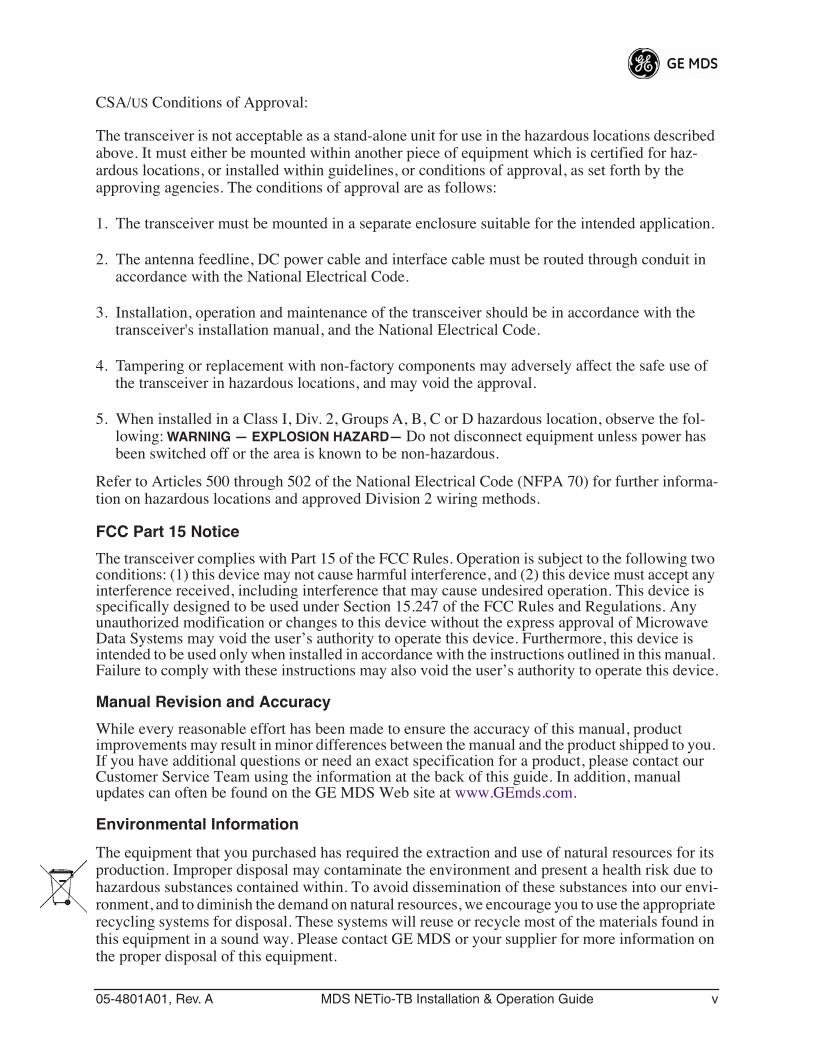
U.S. Installations:
Professional installation required. The radio equipment described in this guide emits radio frequency energy. Although the power level is low, the concentrated energy from a directional antenna may pose a health hazard. For 900 MHz units, do not allow people to come closer than 23 cm (9 inches) to the antenna. For 2.4 GHz units, do not allow people to come closer than 5 cm (2 inches) to the antenna. These distances apply whether the transmitter is operated in indoor or outdoor environments.
For units with the optional wireless expansion service (WeXP) installed, a minimum sepa-ration distance of 23cm (9.05") must be maintained between the two antennas (Link and WeXP) when mounted in their final locations.
More information on RF exposure is available on the Internet at
www.fcc.gov/oet/info/documents/bulletins
.
RF Exposure
05-4801A01, Rev. A MDS NETio-TB Installation & Operation Guide v
CSA/
US
Conditions of Approval:
The transceiver is not acceptable as a stand-alone unit for use in the hazardous locations described above. It must either be mounted within another piece of equipment which is certified for haz-ardous locations, or installed within guidelines, or conditions of approval, as set forth by the approving agencies. The conditions of approval are as follows:
1. The transceiver must be mounted in a separate enclosure suitable for the intended application.
2. The antenna feedline, DC power cable and interface cable must be routed through conduit in accordance with the National Electrical Code.
3. Installation, operation and maintenance of the transceiver should be in accordance with the transceiver's installation manual, and the National Electrical Code.
4. Tampering or replacement with non-factory components may adversely affect the safe use of the transceiver in hazardous locations, and may void the approval.
5. When installed in a Class I, Div. 2, Groups A, B, C or D hazardous location, observe the fol-lowing:
WARNING — EXPLOSION HAZARD—
Do not disconnect equipment unless power has been switched off or the area is known to be non-hazardous.
Refer to Articles 500 through 502 of the National Electrical Code (NFPA 70) for further informa-tion on hazardous locations and approved Division 2 wiring methods.
FCC Part 15 Notice
The transceiver complies with Part 15 of the FCC Rules. Operation is subject to the following two conditions: (1) this device may not cause harmful interference, and (2) this device must accept any interference received, including interference that may cause undesired operation. This device is specifically designed to be used under Section 15.247 of the FCC Rules and Regulations. Any unauthorized modification or changes to this device without the express approval of Microwave Data Systems may void the user’s authority to operate this device. Furthermore, this device is intended to be used only when installed in accordance with the instructions outlined in this manual. Failure to comply with these instructions may also void the user’s authority to operate this device.
Manual Revision and Accuracy
While every reasonable effort has been made to ensure the accuracy of this manual, product improvements may result in minor differences between the manual and the product shipped to you. If you have additional questions or need an exact specification for a product, please contact our Customer Service Team using the information at the back of this guide. In addition, manual updates can often be found on the GE MDS Web site at www.GEmds.com.
Environmental Information
The equipment that you purchased has required the extraction and use of natural resources for its production. Improper disposal may contaminate the environment and present a health risk due to hazardous substances contained within. To avoid dissemination of these substances into our envi-ronment, and to diminish the demand on natural resources, we encourage you to use the appropriate recycling systems for disposal. These systems will reuse or recycle most of the materials found in this equipment in a sound way. Please contact GE MDS or your supplier for more information on the proper disposal of this equipment.

vi MDS NETio-TB Installation & Operation Guide 05-4801A01, Rev. A
05-4801A01, Rev. A MDS NETio-TB Installation & Operation Guide 1
1
INTRODUCING THE MDS NETio SYSTEM
1 Chapter Counter Reset Paragraph
1.1 ABOUT THIS MANUAL ........................................................... 3
1.1.1 Conventions Used .................................................................... 3
1.2 PRODUCT DESCRIPTION ..................................................... 3
1.3 HOW IT WORKS ..................................................................... 5
1.3.1 I/O Operating Modes ................................................................ 51.3.2 Configuration Levels ................................................................. 61.3.3 Module Profiles ........................................................................ 6
1.4 CONNECTOR OVERVIEW...................................................... 7
1.5 DIN RAIL MOUNTING & REMOVAL ...................................... 9
1.6 ACCESSORIES....................................................................... 11
2 MDS NETio-TB Installation & Operation Guide 05-4801A01, Rev. A
05-4801A01, Rev. A MDS NETio-TB Installation & Operation Guide 3
1.1 ABOUT THIS MANUAL
This guide provides installation and operating instructions for MDS NETio Series products. It is arranged into the following chapters:
• Chapter 1—Introducing the MDS NETio System (Page 3)• Chapter 2—Configuring Wireless System Parameters (Page 13)• Chapter 3—I/O Point Configuration (Page 31)• Chapter 4—Wiring and Terminations (Page 45)• Chapter 5—Serial or IP/Ethernet Configuration (Page 59)• Chapter 6—Maintenance & Support Functions (Page 69)
1.1.1 Conventions Used
Quick Start Steps—How to Use Them...
You will find
Quick Start Step
headings presented in the left-hand mar-gins of Chapters 2 and 3. These headings indicate essential steps for get-ting the NETio system up and running. If you only need to perform basic setup and configuration, look for these headings and follow the instruc-tions given. The steps should be performed in sequence.
Additional detail is provided for each menu screen to assist those needing more information.
Menu Navigation—Finding the Menu You Need...
To help show the path to a menu selection, navigation strings are used in several places in this manual. For example, suppose you wished to access the I/O Module Configuration Menu. The navigation string shown in the text would appear as follows:
Main Menu>I/O Network>I/O Module Configuration
By following this order of menus, you will quickly reach the I/O Module Configuration Menu.
1.2 PRODUCT DESCRIPTION
MDS NETio is an integrated, scalable family of wireless communica-tion products for analog and discrete I/O signals. It supports three pri-mary functions that can be implemented separately or concurrently:
•
I/O Signal Extension
—This function allows acquiring, trans-mitting and regenerating I/O signals between control and mon-itoring devices such as PLCs or RTUs.
•
Protocol Node
—Allows direct addressing of I/O using a com-mercial protocol such as MODBUS. Consult the factory for a complete list of the protocols supported in the NETio Protocol Library.
•
Payload Communication
—Accommodates the serial connec-tion of a separate PLC, RTU or other peripheral device for wire-less connectivity to host devices or systems.
4 MDS NETio-TB Installation & Operation Guide 05-4801A01, Rev. A
Invisible place holder
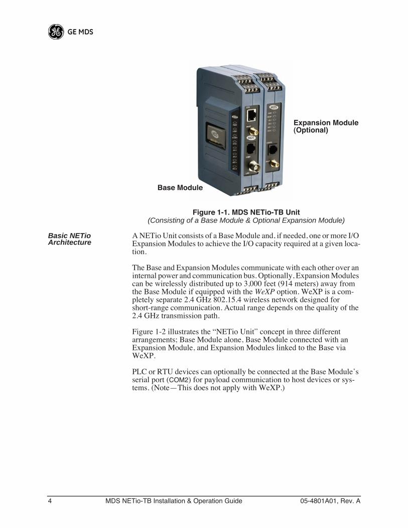
Figure 1-1. MDS NETio-TB Unit
(Consisting of a Base Module & Optional Expansion Module)
Basic NETio Architecture
A NETio Unit consists of a Base Module and, if needed, one or more I/O Expansion Modules to achieve the I/O capacity required at a given loca-tion.
The Base and Expansion Modules communicate with each other over an internal power and communication bus. Optionally, Expansion Modules can be wirelessly distributed up to 3,000 feet (914 meters) away from the Base Module if equipped with the
WeXP
option. WeXP is a com-pletely separate 2.4 GHz 802.15.4 wireless network designed for short-range communication. Actual range depends on the quality of the 2.4 GHz transmission path.
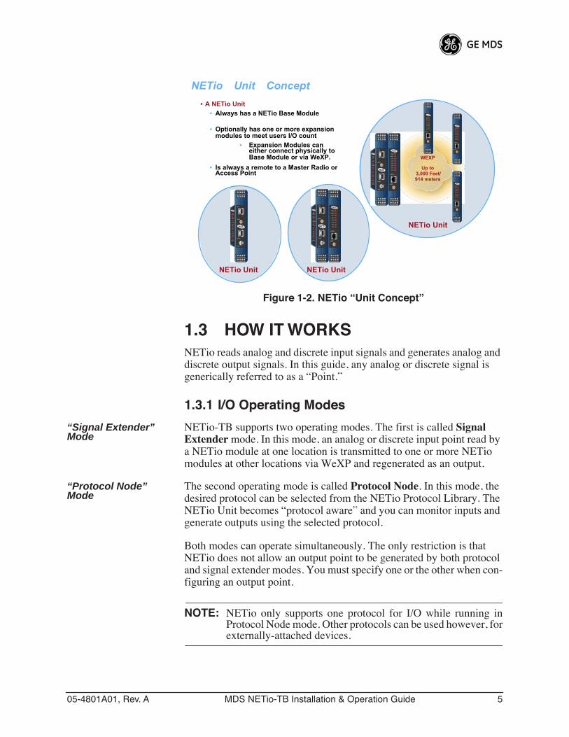
Figure 1-2 illustrates the “NETio Unit” concept in three different arrangements; Base Module alone, Base Module connected with an Expansion Module, and Expansion Modules linked to the Base via WeXP.
PLC or RTU devices can optionally be connected at the Base Module’s serial port (
COM2
) for payload communication to host devices or sys-tems. (Note—This does not apply with WeXP.)
Base Module
Expansion Module(Optional)
05-4801A01, Rev. A MDS NETio-TB Installation & Operation Guide 5
Invisible place holder
Figure 1-2. NETio “Unit Concept”
1.3 HOW IT WORKS
NETio reads analog and discrete input signals and generates analog and discrete output signals. In this guide, any analog or discrete signal is generically referred to as a “Point.”
1.3.1 I/O Operating Modes
“Signal Extender” Mode
NETio-TB supports two operating modes. The first is called
Signal Extender
mode. In this mode, an analog or discrete input point read by a NETio module at one location is transmitted to one or more NETio modules at other locations via WeXP and regenerated as an output.
“Protocol Node” Mode
The second operating mode is called
Protocol Node
. In this mode, the desired protocol can be selected from the NETio Protocol Library. The NETio Unit becomes “protocol aware” and you can monitor inputs and generate outputs using the selected protocol.
Both modes can operate simultaneously. The only restriction is that NETio does not allow an output point to be generated by both protocol and signal extender modes. You must specify one or the other when con-figuring an output point.
NOTE:
NETio only supports one protocol for I/O while running inProtocol Node mode. Other protocols can be used however, for
externally-attached devices.
WEXP
Up to 3,000 Feet/914 meters
NETio �Unit� Concept• A NETio Unit�
• Always has a NETio Base Module
• Optionally has one or more expansionmodules to meet users I/O count
• Expansion Modules caneither connect physically toBase Module or via WeXP.
• Is always a remote to a Master Radio orAccess Point
NETio Unit NETio Unit
NETio Unit
6 MDS NETio-TB Installation & Operation Guide 05-4801A01, Rev. A
1.3.2 Configuration Levels
There are several configuration levels associated with a NETio Unit depending upon the functionality that needs to be implemented.
• NETio TransNET-class Radio Parameters• WeXP 2.4 GHz Parameters (As needed, if WeXP is used)
• WeXP Network Address—Base Module and Wireless Expansion Modules.
• NETio Module Activation (Required)• Unit ID—Base Module ID• Module ID—Expansion Module ID (if used)
• I/O Points (Required)• I/O Point parameters such as signal type and range
• Signal Extender Functions (As needed)• Protocol Node Functions (As needed)• Optional Payload Communication (As needed)• Support for an external RTU or PLC connected to NETio
serial communication port.
These Configuration Levels are further discussed in Chapters 2 and 3.
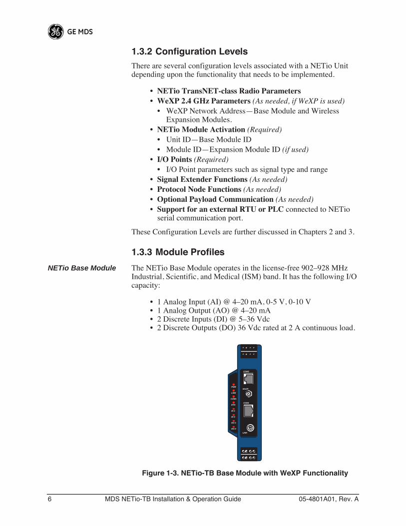
1.3.3 Module Profiles
NETio Base Module The NETio Base Module operates in the license-free 902–928 MHz Industrial, Scientific, and Medical (ISM) band. It has the following I/O capacity:
• 1 Analog Input (AI) @ 4–20 mA, 0-5 V, 0-10 V• 1 Analog Output (AO) @ 4–20 mA• 2 Discrete Inputs (DI) @ 5–36 Vdc• 2 Discrete Outputs (DO) 36 Vdc rated at 2 A continuous load.
Invisible place holder
Figure 1-3. NETio-TB Base Module with WeXP Functionality
COM1
PWR
LINK
COM1
ETH
DI-1
DI-2
DO-1
DO-2
LINK
WeXP
COM2
05-4801A01, Rev. A MDS NETio-TB Installation & Operation Guide 7
Invisible place holder
NETio-XM Expansion Module
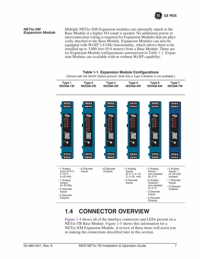
Multiple NETio-XM Expansion modules can optionally attach to the Base Module if a higher I/O count is needed. No additional power or interconnection wiring is required for Expansion Modules that are phys-ically attached to the Base Module. Expansion Modules can also be equipped with WeXP 2.4 GHz functionality, which allows them to be installed up to 3,000 feet (914 meters) from a Base Module. There are six Expansion Module configurations summarized in Table 1-1. Expan-sion Modules are available with or without WeXP capability.
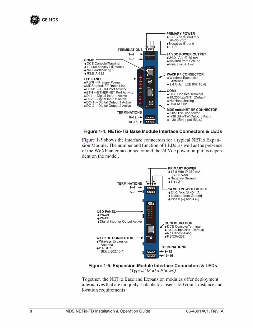
1.4 CONNECTOR OVERVIEWFigure 1-4 shows all of the interface connectors and LEDs present on a NETio-TB Base Module. Figure 1-5 shows this information for a NETio-XM Expansion Module. A review of these items will assist you in making the connections described later in this section.
Table 1-1. Expansion Module Configurations(Shown with the WeXP Option present. Note that a Type 5 Module is not available.)
Type 1NIOXM-1W
Type 2NIOXM-2W
Type 3NIOXM-3W
Type 4NIOXM-4W
Type 6NIOXM-6W
Type 7NIOXM-7W
• 1 Analog Input (0–5 V, 0–10 V, 4–20 mA)
• 1 Analog Output (4–20 Ma)
• 2 Discrete Inputs
• 2 Discrete Outputs
• 6 Discrete Inputs
• 6 Discrete Outputs
• 2 Analog Inputs (0–5 V, 0–10 V, 4–20 mA)
• 4 Discrete Inputs
• 2 Analog Inputs—non-isolated(0–5 V)
• 2 Analog Outputs—non-isolated(0–5 V)
• 2 Discrete Inputs
• 2 Discrete Outputs
• 2 Analog Inputs—(4–20 mA)isolated
• 1 Discrete Inputs
• 3 Discrete Outputs
PWR
WeXP
DI-1
DI-2
DO-1
DO-2
WeXP
CONFIG
PWR
WeXP
DI-1
DI-2
DI-3
DI-4
DI-5
DI-6
WeXP
CONFIG
WeXP
CONFIG
PWR
WeXP
DO-1
DO-2
DO-3
DO-4
DO-5
DO-6
PWR
WeXP
DI-1
DI-2
DI-3
DI-4
WeXP
CONFIG
PWR
WeXP
DI-1
DI-2
DO-1
DO-2
WeXP
CONFIG
PWR
WeXP
DI-1
D0-1
DO-2
DO-3
WeXP
CONFIG
8 MDS NETio-TB Installation & Operation Guide 05-4801A01, Rev. A
Invisible place holder
Figure 1-4. NETio-TB Base Module Interface Connectors & LEDs
Figure 1-5 shows the interface connectors for a typical NETio Expan-sion Module. The number and function of LEDs, as well as the presence of the WeXP antenna connector and the 24 Vdc power output, is depen-dent on the model.
Invisible place holder
Figure 1-5. Expansion Module Interface Connectors & LEDs(Typical Model Shown)
Together, the NETio Base and Expansion modules offer deployment alternatives that are uniquely scalable to a user’s I/O count, distance and location requirements.
COM1
PWR
LINK
COM1
ETH
DI-1
DI-2
DO-1
DO-2
LINK
WeXP
COM2
PRIMARY POWER◆ 13.8 Vdc @ 350 mA (6–30 Vdc)◆ Negative Ground◆ 1 + / 2 –
24 VDC POWER OUTPUT◆ 24.0 Vdc @ 40 mA◆ Isolated from Ground◆ Pins 3 (+) & 4 (–)
COM1◆ DCE Console/Terminal◆ 19,200 bps/8N1 (Default)◆ No Handshaking◆ RS/EIA-232
MDS entraNET RF CONNECTOR◆ 50Ω TNC connector◆ +30 dBm/1W Output (Max.)◆ –30 dBm Input (Max.)
WeXP RF CONNECTOR◆ Wireless Expansion◆ Antenna◆ 2.4 GHz (IEEE 802.15.4)
9–1213–16
TERMINATIONS
LED PANEL◆ PWR —Primary Power◆ MDS entraNET Radio Link◆ COM1 —COM Port Activity◆ ETH —ETHERNET Port Activity◆ DI-1 —Digital Input 1 Active◆ DI-2 —Digital Input 2 Active◆ DO-1 —Digital Output 1 Active◆ DO-2 —Digital Output 2 Active
1–45–8
TERMINATIONS+ – –+
COM2◆ DCE Console/Terminal◆ 19,200 bps/8N1 (Default)◆ No Handshaking◆ RS/EIA-232
WeXP RF CONNECTOR◆ Wireless Expansion◆ Antenna◆ 2.4 GHz◆ (IEEE 802.15.4)
CONFIGURATION◆ DCE Console/Terminal◆ 19,200 bps/8N1 (Default)◆ No Handshaking◆ RS/EIA-232
1–45–8
TERMINATIONS
9–1213–16
TERMINATIONS
LED PANEL◆ Power◆ WeXP◆ Digital Input or Output Active
+ – –+
PWR
WeXP
DI-1
DI-2
DI-3
DI-4
WeXP
CONFIG
PRIMARY POWER◆ 13.8 Vdc @ 350 mA (6–30 Vdc)◆ Negative Ground◆ 1 + / 2 –
24 VDC POWER OUTPUT◆ 24.0 Vdc @ 40 mA◆ Isolated from Ground◆ Pins 3 (+) and 4 (–)
05-4801A01, Rev. A MDS NETio-TB Installation & Operation Guide 9
The NETio Base Module can be purchased with two different levels of service:
NETio Protocol Node—Supports access to the protocol library for direct protocol addressability.
NETio Complete—Adds concurrent payload communication for an attached RTU, PLC or other peripheral device, and signal extension via WeXP to protocol capabilities. Serial connections are supported. WeXP is also included for short-range linkage to Wireless Expansion Modules installed up to 3,000 feet (914 meters) away.
Key Operating Features
• Ability to read analog inputs and discrete inputs• Ability to generate analog outputs and discrete outputs• Protocol-addressable analog and discrete points via a serial con-
nection• Analog and discrete signal regeneration between devices via
WeXP• NETio Wireless Expansion capability—WeXP• Serial communication for an external RTU or PLC
Rugged Packaging MDS NETio modules are housed in compact and rugged high-impact cases that need only be protected from direct exposure to the weather. The modules are supplied with 35 mm DIN-rail brackets for quick and easy installation.
Robust Radio Operation
The transceivers are designed for frequency-hopping spread-spectrum operation in the license-free 900 MHz or 2.4 GHz band. They can pro-vide reliable long distance communications over line-of-sight signal paths. They employ digital signal processing (DSP) techniques for high performance operation, even in the presence of weak signals or interfer-ence.
Multiple Services Users with a mixture of equipment requiring serial data interfaces can employ a combination of both NETio modules and MDS TransNET Remotes communicating with a common MDS TransNET Master Radio.
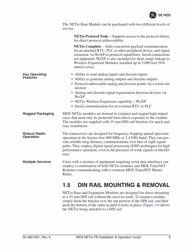
1.5 DIN RAIL MOUNTING & REMOVALNETio Base and Expansion Modules are designed for direct mounting to a 35 mm DIN rail without the need for tools. To mount a module, simply hook the bracket over the top portion of the DIN rail, and then push the bottom of the radio in until it locks in place. Figure 1-6 shows the NETio being attached to a DIN rail.
10 MDS NETio-TB Installation & Operation Guide 05-4801A01, Rev. A
Invisible place holder
Figure 1-6. Mounting NETio Equipment to DIN Rail(Hook unit over top of rail, and push in at bottom)
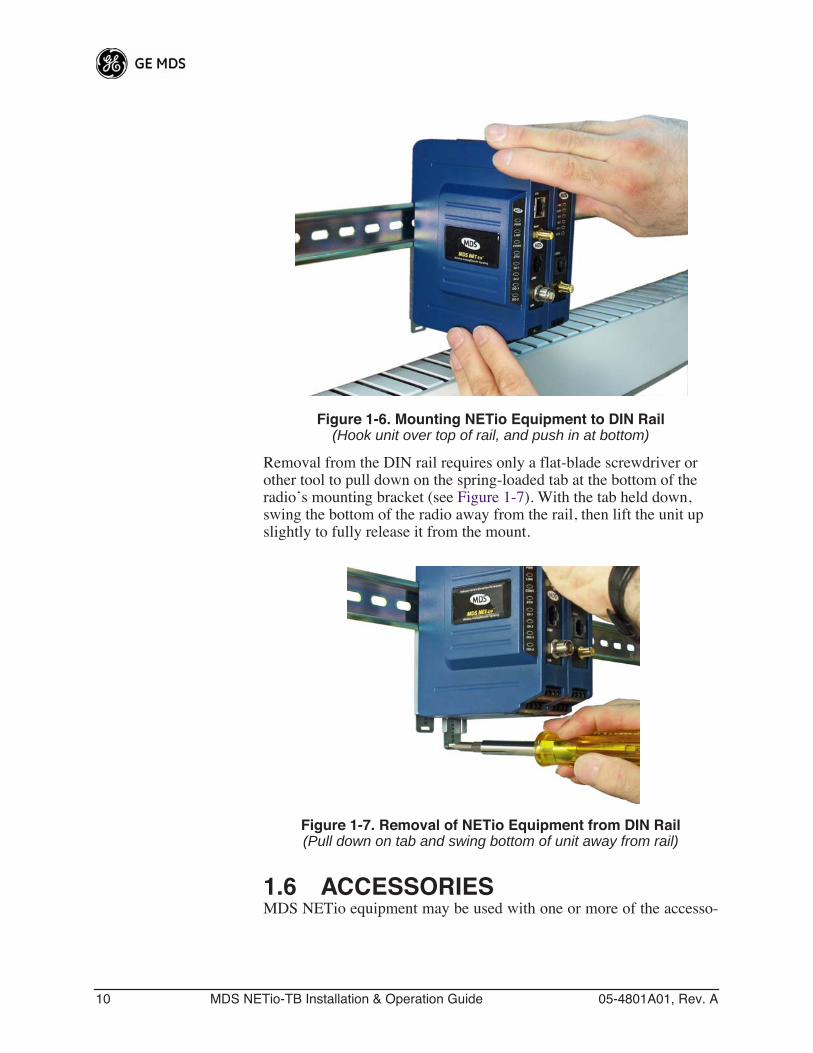
Removal from the DIN rail requires only a flat-blade screwdriver or other tool to pull down on the spring-loaded tab at the bottom of the radio’s mounting bracket (see Figure 1-7). With the tab held down, swing the bottom of the radio away from the rail, then lift the unit up slightly to fully release it from the mount.
Invisible place holder
Figure 1-7. Removal of NETio Equipment from DIN Rail(Pull down on tab and swing bottom of unit away from rail)
1.6 ACCESSORIESMDS NETio equipment may be used with one or more of the accesso-
05-4801A01, Rev. A MDS NETio-TB Installation & Operation Guide 11
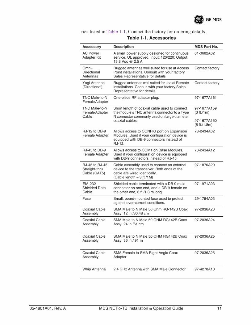
ries listed in Table 1-1. Contact the factory for ordering details.Table 1-1. Accessories
Accessory Description MDS Part No.
AC Power Adapter Kit
A small power supply designed for continuous service. UL approved. Input: 120/220; Output: 13.8 Vdc @ 2.5 A
01-3682A02
Omni- Directional Antennas
Rugged antennas well suited for use at Access Point installations. Consult with your factory Sales Representative for details
Contact factory
Yagi Antenna(Directional)
Rugged antennas well suited for use at Remote installations. Consult with your factory Sales Representative for details.
Contact factory
TNC Male-to-N Female Adapter
One-piece RF adaptor plug. 97-1677A161
TNC Male-to-N Female Adapter Cable
Short length of coaxial cable used to connect the module’s TNC antenna connector to a Type N connector commonly used on large diameter coaxial cables.
97-1677A159(3 ft./1m)
97-1677A160(6 ft./1.8m)
RJ-12 to DB-9 Female Adapter
Allows access to CONFIG port on Expansion Modules. Used if your configuration device is equipped with DB-9 connectors instead of RJ-12.
73-2434A02
RJ-45 to DB-9 Female Adapter
Allows access to COM1 on Base Modules. Used if your configuration device is equipped with DB-9 connectors instead of RJ-45.
73-2434A12
RJ-45 to RJ-45 Straight-thru Cable (CAT5)
Cable assembly used to connect an external device to the transceiver. Both ends of the cable are wired identically.(Cable length ≈ 3 ft./1M)
97-1870A20
EIA-232 Shielded Data Cable
Shielded cable terminated with a DB-9 male connector on one end, and a DB-9 female on the other end, 6 ft./1.8 m long.
97-1971A03
Fuse Small, board-mounted fuse used to protect against over-current conditions.
29-1784A03
Coaxial Cable Assembly
SMA Male to N Male 50 Ohm RG-142B Coax Assy. 12 in./30.48 cm
97-2036A23
Coaxial Cable Assembly
SMA Male to N Male 50 OHM RG142B Coax Assy. 24 in./61 cm
97-2036A24
Coaxial Cable Assembly
SMA Male to N Male 50 OHM RG142B Coax Assy. 36 in./.91 m
97-2036A25
Coaxial Cable Assembly
SMA Female to SMA Right Angle Coax Adapter
97-2036A26
Whip Antenna 2.4 GHz Antenna with SMA Male Connector 97-4278A10

12 MDS NETio-TB Installation & Operation Guide 05-4801A01, Rev. A
05-4801A01, Rev. A MDS NETio-TB Installation & Operation Guide 13
2 CONFIGURING WIRELESSSYSTEM PARAMETERS
2 Chapter Counter Reset Paragraph2.1 INTRODUCTION 17
2.2 INITIAL SETUP 17
2.2.1 NETio Backplane Communication 182.2.2 Measure & Connect DC Power 18
2.3 SET BASIC CONFIGURATION OF THE NETio BASE MODULE19
2.3.1 Starting Information Screen 202.3.2 Main Menu 222.3.3 Wireless Configuration Menu 222.3.4 TransNET Configuration 232.3.5 WeXP Configuration Menu 242.3.6 Wireless Expansion Module Configuration 25
2.4 ASSIGNING MODULE IDs 26
2.4.1 ID Conflict List Menu 282.4.2 Conflict (Resolution) Menu 292.4.3 Configuring WeXP Wireless Expansion Modules 292.4.4 I/O Module Configuration Menu 302.4.5 Module Menu 31
2.5 CHECK for NORMAL OPERATION 31

14 MDS NETio-TB Installation & Operation Guide 05-4801A01, Rev. A
05-4801A01, Rev. A MDS NETio-TB Installation & Operation Guide 15
2.1 INTRODUCTIONPrior to installation, it is recommended that the equipment be set up in a benchtop environment to become familiar with its operation and fea-tures. This also allows tests of various network designs and configura-tions prior to installation. A benchtop test can be performed with any number of modules.
This section describes the hardware setup and software configuration of NETio. Quick Start steps are provided to assist installers who only wish to perform basic setup and configuration tasks. Additional detail is pro-vided for each step, for those wishing to obtain more background. infor-mation.
2.2 INITIAL SETUPThe following steps explain how to make connections to NETio, power it up, and set basic configuration.
Quick Start Step #1:
Review power and module interconnection discussion below, then proceed to Section 2.3.
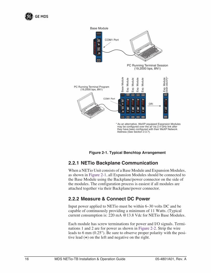
Figure 2-1 is a drawing of a benchtop arrangement for configuration and staging of NETio equipment. The NETio modules may also be installed on DIN rails if desired (see “ DIN RAIL MOUNTING & REMOVAL” on Page 9).
16 MDS NETio-TB Installation & Operation Guide 05-4801A01, Rev. A
Invisible place holder
Figure 2-1. Typical Benchtop Arrangement
2.2.1 NETio Backplane CommunicationWhen a NETio Unit consists of a Base Module and Expansion Modules, as shown in Figure 2-1, all Expansion Modules should be connected to the Base Module using the Backplane/power connector on the side of the modules. The configuration process is easiest if all modules are attached together via their Backplane/power connector.
2.2.2 Measure & Connect DC PowerInput power applied to NETio must be within 6–30 volts DC and be capable of continuously providing a minimum of 11 Watts. (Typical current consumption is: 220 mA @13.8 Vdc for NETio Base Modules.
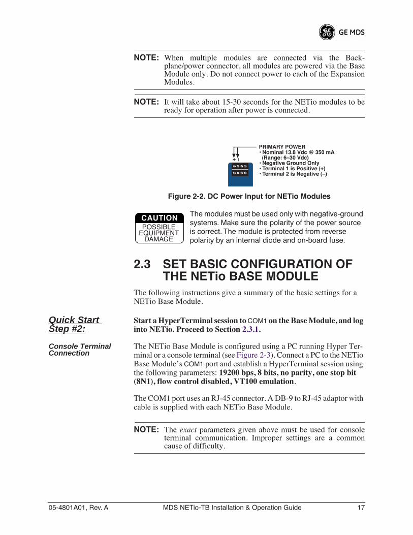
Each module has screw terminations for power and I/O signals. Termi-nations 1 and 2 are for power as shown in Figure 2-2. Strip the wire leads to 6 mm (0.25"). Be sure to observe proper polarity with the posi-tive lead (+) on the left and negative on the right.
PC Running Terminal Session(19,2000 bps, 8N1)
Base Module
COM1 PortETH
COM1
PWR
LINK
COM1
ETH
DI-1
DI-2
DO-1
DO-2
LINK
ETH
WeXP
PC Running Terminal Program(19,2000 bps, 8N1)
OR:
* As an alternative, WeXP-equipped Expansion Modules may be configured over the air via 2.4 GHz link after they have been configured with their WeXP Network Address (See Section 2.3.7).
Bas
e M
odul
e
COM1 Port ETH
COM1
PWR
LINK
COM1
ETH
DI-1
DI-2
DO-1
DO-2
LINK
ETH
WeXP
PWR
WeXP
DI-1
DI-2
DI-3
DI-4
WeXP
CONFIG
PWR
WeXP
DI-1
DI-2
DI-3
DI-4
WeXP
CONFIG
PWR
WeXP
DI-1
DI-2
DI-3
DI-4
WeXP
CONFIG
PWR
WeXP
DI-1
DI-2
DI-3
DI-4
WeXP
CONFIG
Exp
. Mod
ule
Exp
. Mod
ule
Exp
. Mod
ule
Exp
. Mod
ule
Exp
. Mod
ule
(With
WeX
P)*
PWR
WeXP
DI-1
DI-2
DI-3
DI-4
WeXP
CONFIG
Bas
e M
odul
eB
ase
Mod
ule
05-4801A01, Rev. A MDS NETio-TB Installation & Operation Guide 17
NOTE: When multiple modules are connected via the Back-plane/power connector, all modules are powered via the BaseModule only. Do not connect power to each of the ExpansionModules.
NOTE: It will take about 15-30 seconds for the NETio modules to beready for operation after power is connected.
Invisible place holder
Figure 2-2. DC Power Input for NETio Modules
The modules must be used only with negative-ground systems. Make sure the polarity of the power source is correct. The module is protected from reverse polarity by an internal diode and on-board fuse.
2.3 SET BASIC CONFIGURATION OF THE NETio BASE MODULE
The following instructions give a summary of the basic settings for a NETio Base Module.
Quick Start Step #2:
Start a HyperTerminal session to COM1 on the Base Module, and log into NETio. Proceed to Section 2.3.1.
Console Terminal Connection
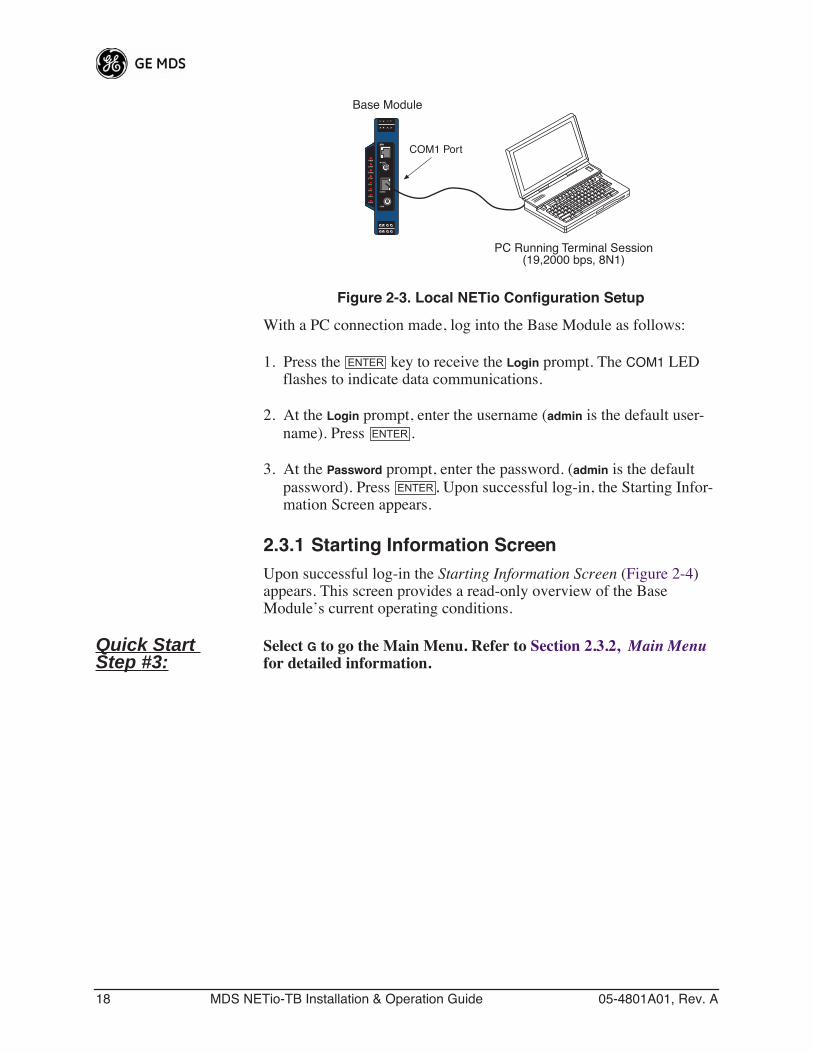
The NETio Base Module is configured using a PC running Hyper Ter-minal or a console terminal (see Figure 2-3). Connect a PC to the NETio Base Module’s COM1 port and establish a HyperTerminal session using the following parameters: 19200 bps, 8 bits, no parity, one stop bit (8N1), flow control disabled, VT100 emulation.
The COM1 port uses an RJ-45 connector. A DB-9 to RJ-45 adaptor with cable is supplied with each NETio Base Module.
NOTE: The exact parameters given above must be used for consoleterminal communication. Improper settings are a commoncause of difficulty.
+ –
PRIMARY POWER• Nominal 13.8 Vdc @ 350 mA (Range: 6–30 Vdc)• Negative Ground Only• Terminal 1 is Positive (+)• Terminal 2 is Negative (–)
CAUTIONPOSSIBLE
EQUIPMENTDAMAGE
18 MDS NETio-TB Installation & Operation Guide 05-4801A01, Rev. A
Invisible place holder
Figure 2-3. Local NETio Configuration Setup
With a PC connection made, log into the Base Module as follows:
1. Press the key to receive the Login prompt. The COM1 LED flashes to indicate data communications.
2. At the Login prompt, enter the username (admin is the default user-name). Press .
3. At the Password prompt, enter the password. (admin is the default password). Press . Upon successful log-in, the Starting Infor-mation Screen appears.
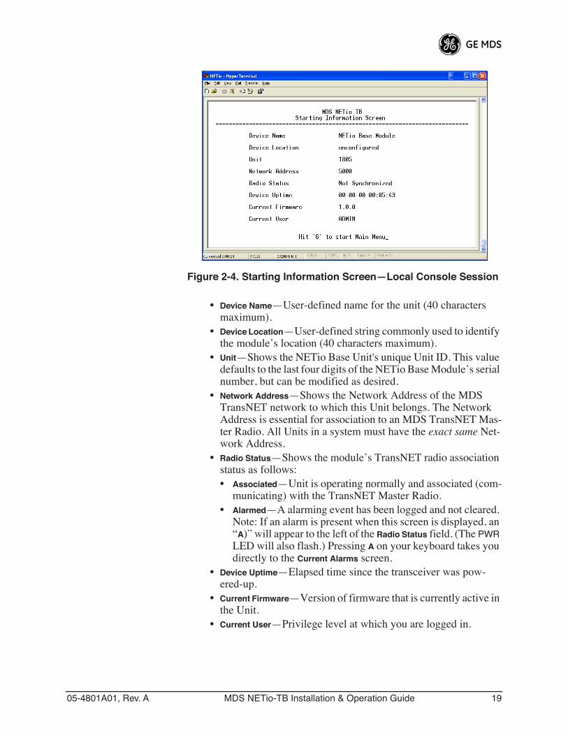
2.3.1 Starting Information ScreenUpon successful log-in the Starting Information Screen (Figure 2-4) appears. This screen provides a read-only overview of the Base Module’s current operating conditions.
Quick Start Step #3:
Select G to go the Main Menu. Refer to Section 2.3.2, Main Menu for detailed information.
PC Running Terminal Session(19,2000 bps, 8N1)
Base Module
COM1 PortETH
COM1
PWR
LINK
COM1
ETH
DI-1
DI-2
DO-1
DO-2
LINK
ETH
WeXP
ENTER
ENTER
ENTER
05-4801A01, Rev. A MDS NETio-TB Installation & Operation Guide 19
Invisible place holder
Figure 2-4. Starting Information Screen—Local Console Session
• Device Name—User-defined name for the unit (40 characters maximum).
• Device Location—User-defined string commonly used to identify the module’s location (40 characters maximum).
• Unit—Shows the NETio Base Unit's unique Unit ID. This value defaults to the last four digits of the NETio Base Module’s serial number, but can be modified as desired.
• Network Address—Shows the Network Address of the MDS TransNET network to which this Unit belongs. The Network Address is essential for association to an MDS TransNET Mas-ter Radio. All Units in a system must have the exact same Net-work Address.
• Radio Status—Shows the module’s TransNET radio association status as follows:• Associated—Unit is operating normally and associated (com-
municating) with the TransNET Master Radio.• Alarmed—A alarming event has been logged and not cleared.
Note: If an alarm is present when this screen is displayed, an “A)” will appear to the left of the Radio Status field. (The PWR LED will also flash.) Pressing A on your keyboard takes you directly to the Current Alarms screen.
• Device Uptime—Elapsed time since the transceiver was pow-ered-up.
• Current Firmware—Version of firmware that is currently active in the Unit.
• Current User—Privilege level at which you are logged in.
20 MDS NETio-TB Installation & Operation Guide 05-4801A01, Rev. A
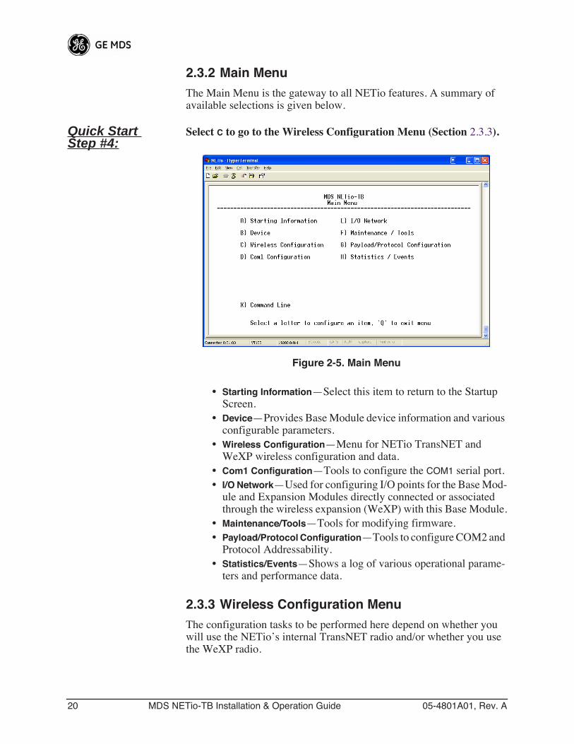
2.3.2 Main MenuThe Main Menu is the gateway to all NETio features. A summary of available selections is given below.
Quick Start Step #4:
Select C to go to the Wireless Configuration Menu (Section 2.3.3).
Invisible place holder
Figure 2-5. Main Menu
• Starting Information—Select this item to return to the Startup Screen.
• Device—Provides Base Module device information and various configurable parameters.
• Wireless Configuration—Menu for NETio TransNET and WeXP wireless configuration and data.
• Com1 Configuration—Tools to configure the COM1 serial port.• I/O Network—Used for configuring I/O points for the Base Mod-
ule and Expansion Modules directly connected or associated through the wireless expansion (WeXP) with this Base Module.
• Maintenance/Tools—Tools for modifying firmware.• Payload/Protocol Configuration—Tools to configure COM2 and
Protocol Addressability.• Statistics/Events—Shows a log of various operational parame-
ters and performance data.
2.3.3 Wireless Configuration MenuThe configuration tasks to be performed here depend on whether you will use the NETio’s internal TransNET radio and/or whether you use the WeXP radio.
05-4801A01, Rev. A MDS NETio-TB Installation & Operation Guide 21
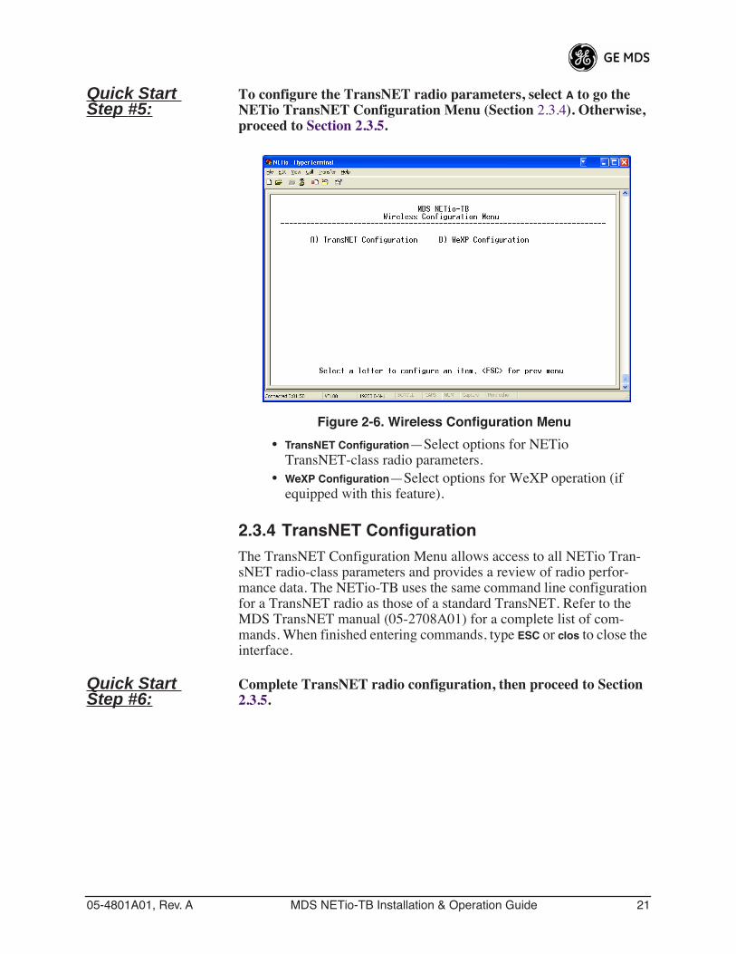
Quick Start Step #5:
To configure the TransNET radio parameters, select A to go the NETio TransNET Configuration Menu (Section 2.3.4). Otherwise, proceed to Section 2.3.5.
Invisible place holder
Figure 2-6. Wireless Configuration Menu
• TransNET Configuration—Select options for NETio TransNET-class radio parameters.
• WeXP Configuration—Select options for WeXP operation (if equipped with this feature).
2.3.4 TransNET ConfigurationThe TransNET Configuration Menu allows access to all NETio Tran-sNET radio-class parameters and provides a review of radio perfor-mance data. The NETio-TB uses the same command line configuration for a TransNET radio as those of a standard TransNET. Refer to the MDS TransNET manual (05-2708A01) for a complete list of com-mands. When finished entering commands, type ESC or clos to close the interface.
Quick Start Step #6:
Complete TransNET radio configuration, then proceed to Section 2.3.5.
22 MDS NETio-TB Installation & Operation Guide 05-4801A01, Rev. A
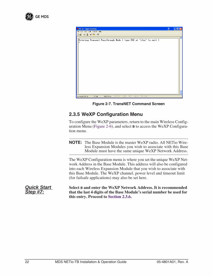
Invisible place holder
Figure 2-7. TransNET Command Screen
2.3.5 WeXP Configuration MenuTo configure the WeXP parameters, return to the main Wireless Config-uration Menu (Figure 2-6), and select B to access the WeXP Configura-tion menu.
NOTE: The Base Module is the master WeXP radio. All NETio Wire-less Expansion Modules you wish to associate with this BaseModule must have the same unique WeXP Network Address.
The WeXP Configuration menu is where you set the unique WeXP Net-work Address in the Base Module. This address will also be configured into each Wireless Expansion Module that you wish to associate with this Base Module. The WeXP channel, power level and timeout limit (for failsafe applications) may also be set here.
Quick Start Step #7:
Select B and enter the WeXP Network Address. It is recommended that the last 4 digits of the Base Module’s serial number be used for this entry. Proceed to Section 2.3.6.
05-4801A01, Rev. A MDS NETio-TB Installation & Operation Guide 23
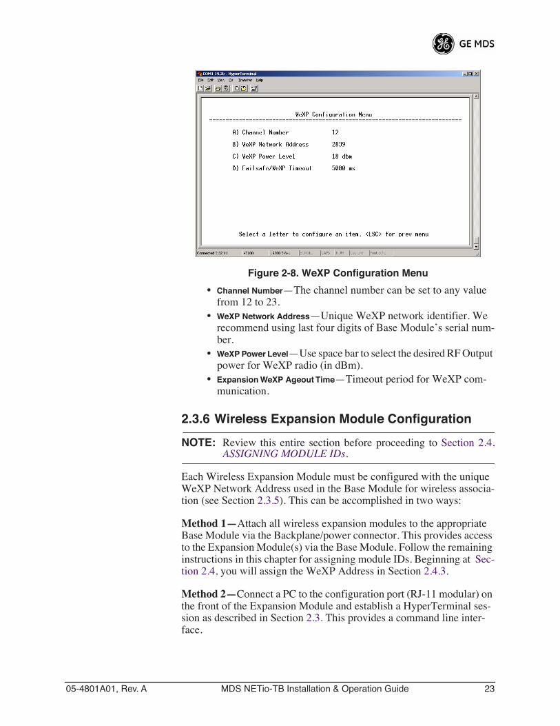
Invisible place holder
Figure 2-8. WeXP Configuration Menu
• Channel Number—The channel number can be set to any value from 12 to 23.
• WeXP Network Address—Unique WeXP network identifier. We recommend using last four digits of Base Module’s serial num-ber.
• WeXP Power Level—Use space bar to select the desired RF Output power for WeXP radio (in dBm).
• Expansion WeXP Ageout Time—Timeout period for WeXP com-munication.
2.3.6 Wireless Expansion Module Configuration
NOTE: Review this entire section before proceeding to Section 2.4,ASSIGNING MODULE IDs.
Each Wireless Expansion Module must be configured with the unique WeXP Network Address used in the Base Module for wireless associa-tion (see Section 2.3.5). This can be accomplished in two ways:
Method 1—Attach all wireless expansion modules to the appropriate Base Module via the Backplane/power connector. This provides access to the Expansion Module(s) via the Base Module. Follow the remaining instructions in this chapter for assigning module IDs. Beginning at Sec-tion 2.4, you will assign the WeXP Address in Section 2.4.3.
Method 2—Connect a PC to the configuration port (RJ-11 modular) on the front of the Expansion Module and establish a HyperTerminal ses-sion as described in Section 2.3. This provides a command line inter-face.
24 MDS NETio-TB Installation & Operation Guide 05-4801A01, Rev. A
Quick Start Step #8:
Using the command line interface, enter the following and press the Return key:
wexp netaddr<WeXP Network Address used in Base Module>
Repeat this step for all Wireless Expansion Modules that are to associate with a particular Base Module. When finished, proceed to Section 2.4.
2.4 ASSIGNING MODULE IDsWhen power is applied to a NETio Base Module, an I/O Network is automatically established for Expansion Modules. The I/O Network is one Base Module (or a Base Module plus Expansion Modules) con-nected physically via the Power/Communication Bus and/or wirelessly via WeXP. Note that only Wireless Expansion Modules whose WeXP Network Address matches the address in the Base Module (see Section 2.3.5) will associate.
The NETio Base Module automatically resolves the quantity, type and connection method for Expansion Modules upon power-up and assigns temporary Module IDs until they are formally configured.
Set Module ID Formally “activate” the Expansion Modules in a NETio Unit by assigning a permanent Module ID to each module.
NOTE: Activation is done through the I/O Network Menu configurationscreens. Upon power-up, all NETio Module(s) will appear firstin the Unconfigured/Conflicting Module menu. Once a Module IDis assigned by the user, the Modules will appear on the I/ONetwork Menu.
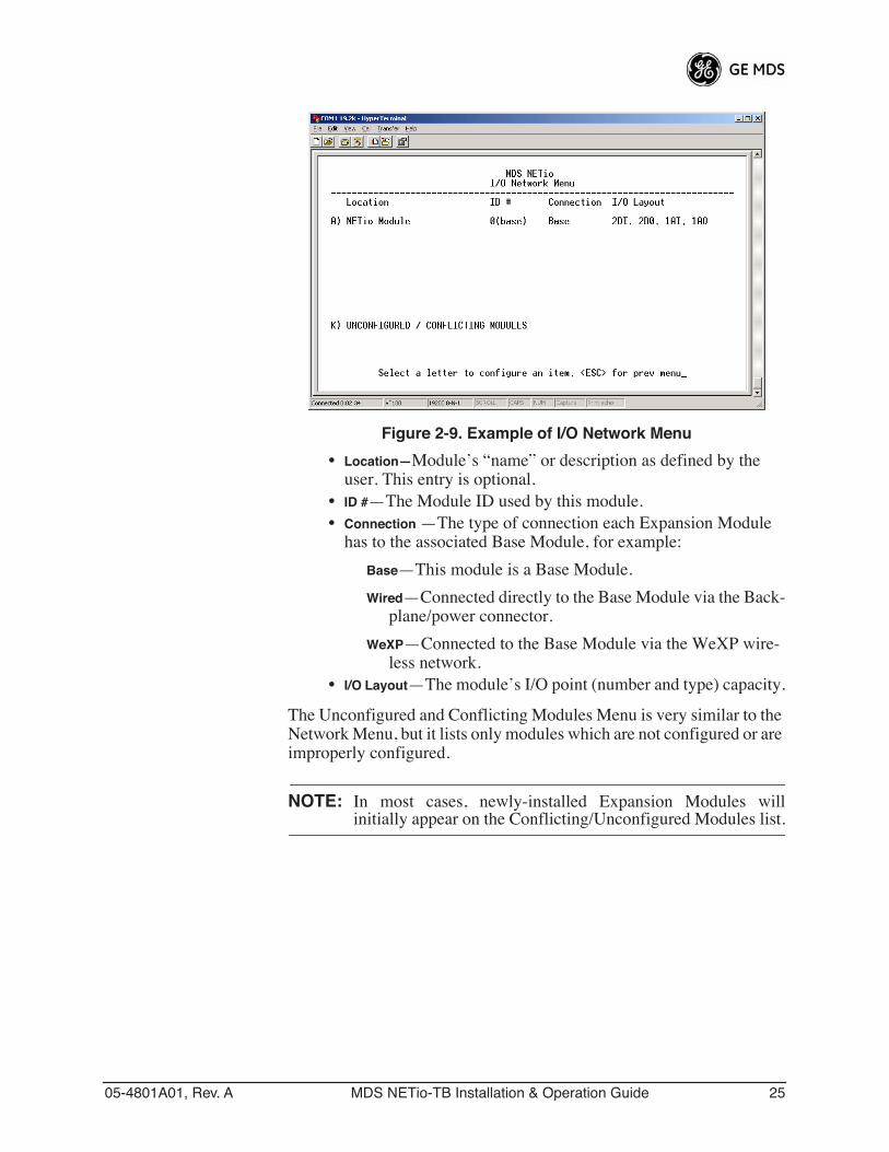
Figure 2-9 is an example of an operational network. If the menu displays UNCONFIGURED/CONFLICTING MODULES, this means there are conflicts that need to be resolved. If this menu option is not shown, then there are no conflicts and you can proceed directly to Section 2.4.3. Selecting the letter associated with a module takes you to its configuration screen.
Quick Start Step #9:
Select K to proceed to the Unconfigured/Conflicting Modules Menu (refer to Section 2.4.1), if shown. Otherwise, proceed to Section 2.4.3, Quick Start Step 12.
05-4801A01, Rev. A MDS NETio-TB Installation & Operation Guide 25
Invisible place holder
Figure 2-9. Example of I/O Network Menu
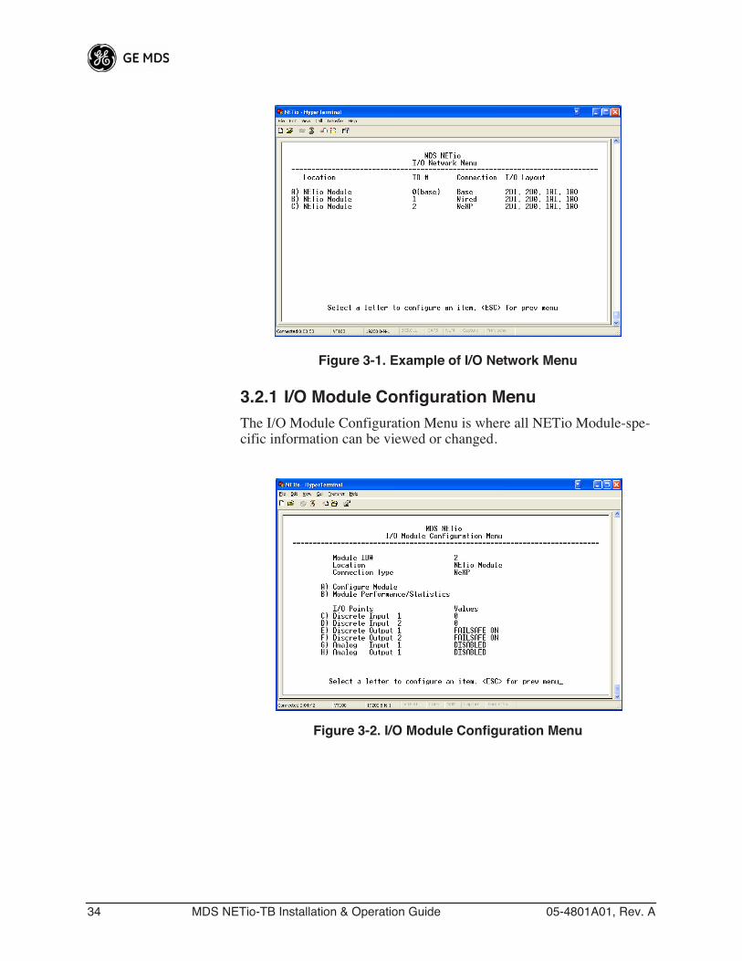
• Location—Module’s “name” or description as defined by the user. This entry is optional.
• ID #—The Module ID used by this module.• Connection —The type of connection each Expansion Module
has to the associated Base Module, for example:
Base—This module is a Base Module.
Wired—Connected directly to the Base Module via the Back-plane/power connector.
WeXP—Connected to the Base Module via the WeXP wire-less network.
• I/O Layout—The module’s I/O point (number and type) capacity.
The Unconfigured and Conflicting Modules Menu is very similar to the Network Menu, but it lists only modules which are not configured or are improperly configured.
NOTE: In most cases, newly-installed Expansion Modules willinitially appear on the Conflicting/Unconfigured Modules list.
26 MDS NETio-TB Installation & Operation Guide 05-4801A01, Rev. A
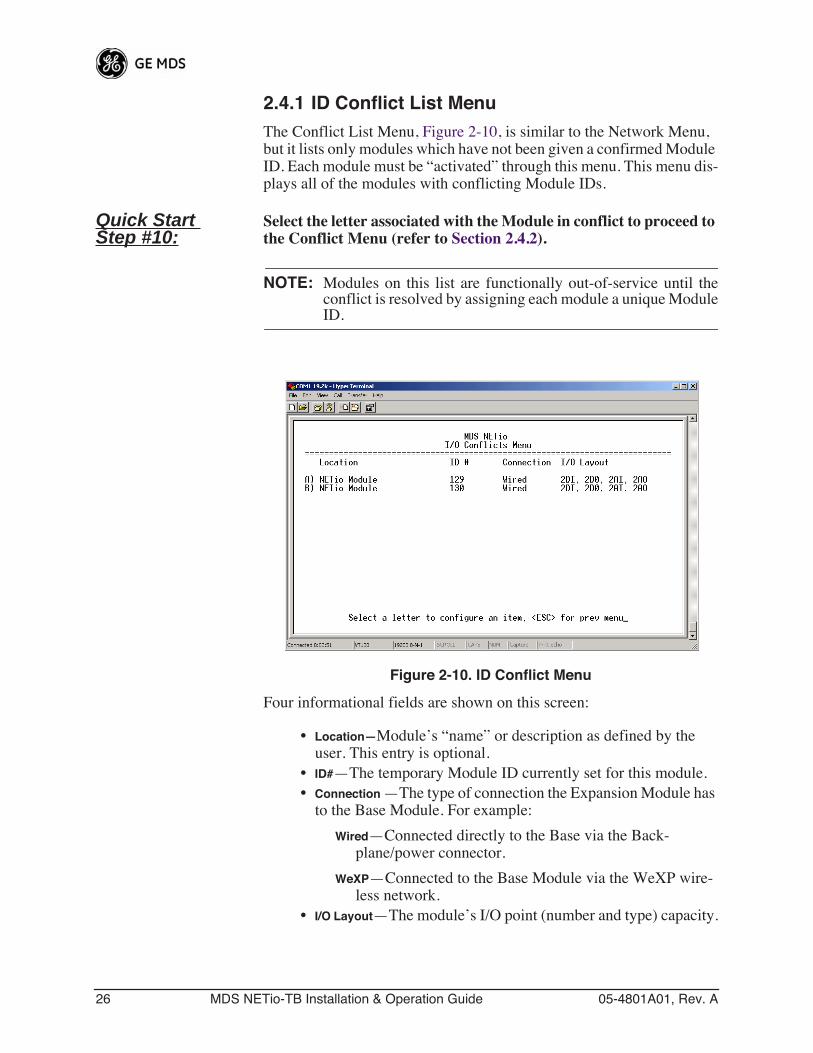
2.4.1 ID Conflict List MenuThe Conflict List Menu, Figure 2-10, is similar to the Network Menu, but it lists only modules which have not been given a confirmed Module ID. Each module must be “activated” through this menu. This menu dis-plays all of the modules with conflicting Module IDs.
Quick Start Step #10:
Select the letter associated with the Module in conflict to proceed to the Conflict Menu (refer to Section 2.4.2).
NOTE: Modules on this list are functionally out-of-service until theconflict is resolved by assigning each module a unique ModuleID.
Invisible place holder
Figure 2-10. ID Conflict Menu
Four informational fields are shown on this screen:
• Location—Module’s “name” or description as defined by the user. This entry is optional.
• ID#—The temporary Module ID currently set for this module.• Connection —The type of connection the Expansion Module has
to the Base Module. For example:
Wired—Connected directly to the Base via the Back-plane/power connector.
WeXP—Connected to the Base Module via the WeXP wire-less network.
• I/O Layout—The module’s I/O point (number and type) capacity.
05-4801A01, Rev. A MDS NETio-TB Installation & Operation Guide 27
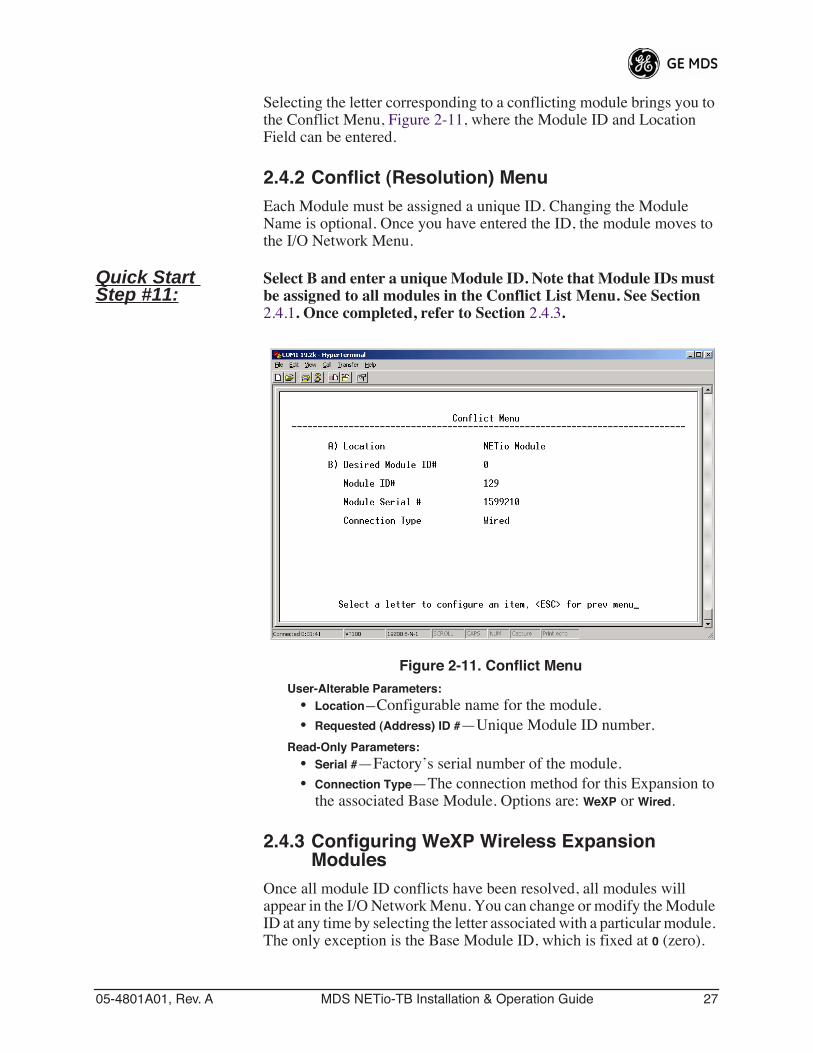
Selecting the letter corresponding to a conflicting module brings you to the Conflict Menu, Figure 2-11, where the Module ID and Location Field can be entered.
2.4.2 Conflict (Resolution) MenuEach Module must be assigned a unique ID. Changing the Module Name is optional. Once you have entered the ID, the module moves to the I/O Network Menu.
Quick Start Step #11:
Select B and enter a unique Module ID. Note that Module IDs must be assigned to all modules in the Conflict List Menu. See Section 2.4.1. Once completed, refer to Section 2.4.3.
Figure 2-11. Conflict Menu
User-Alterable Parameters:• Location—Configurable name for the module.• Requested (Address) ID #—Unique Module ID number.
Read-Only Parameters:• Serial #—Factory’s serial number of the module.• Connection Type—The connection method for this Expansion to
the associated Base Module. Options are: WeXP or Wired.
2.4.3 Configuring WeXP Wireless Expansion Modules
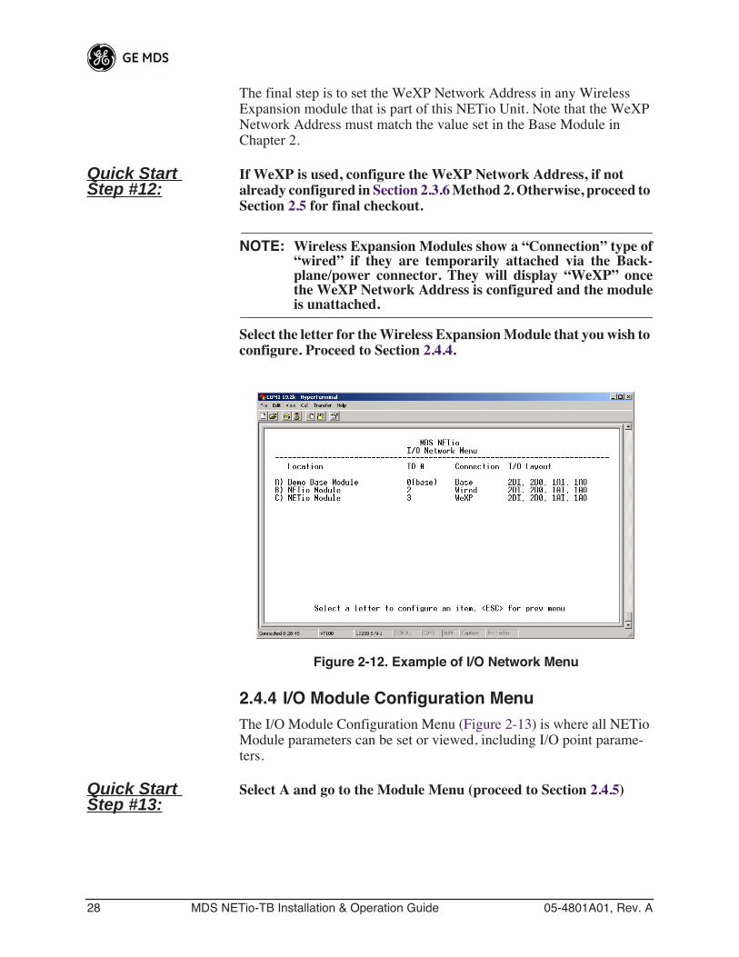
Once all module ID conflicts have been resolved, all modules will appear in the I/O Network Menu. You can change or modify the Module ID at any time by selecting the letter associated with a particular module. The only exception is the Base Module ID, which is fixed at 0 (zero).
28 MDS NETio-TB Installation & Operation Guide 05-4801A01, Rev. A
The final step is to set the WeXP Network Address in any Wireless Expansion module that is part of this NETio Unit. Note that the WeXP Network Address must match the value set in the Base Module in Chapter 2.
Quick Start Step #12:
If WeXP is used, configure the WeXP Network Address, if not already configured in Section 2.3.6 Method 2. Otherwise, proceed to Section 2.5 for final checkout.
NOTE: Wireless Expansion Modules show a “Connection” type of“wired” if they are temporarily attached via the Back-plane/power connector. They will display “WeXP” oncethe WeXP Network Address is configured and the moduleis unattached.
Select the letter for the Wireless Expansion Module that you wish to configure. Proceed to Section 2.4.4.
Figure 2-12. Example of I/O Network Menu
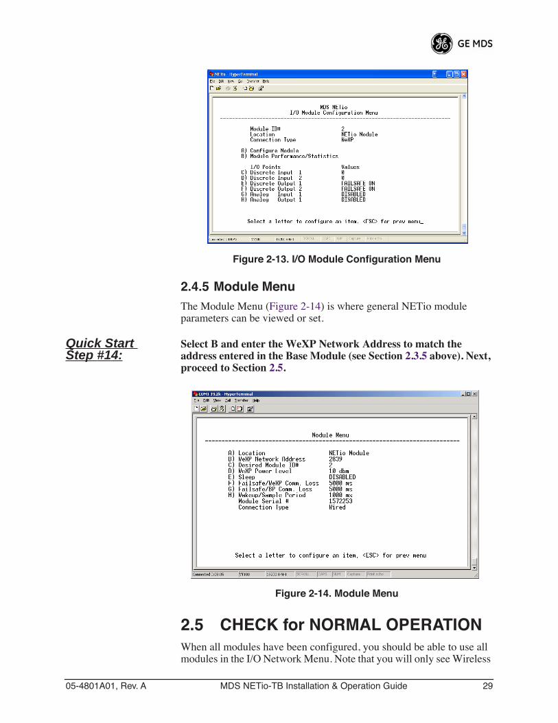
2.4.4 I/O Module Configuration MenuThe I/O Module Configuration Menu (Figure 2-13) is where all NETio Module parameters can be set or viewed, including I/O point parame-ters.
Quick Start Step #13:
Select A and go to the Module Menu (proceed to Section 2.4.5)
05-4801A01, Rev. A MDS NETio-TB Installation & Operation Guide 29
Invisible place holder
Figure 2-13. I/O Module Configuration Menu
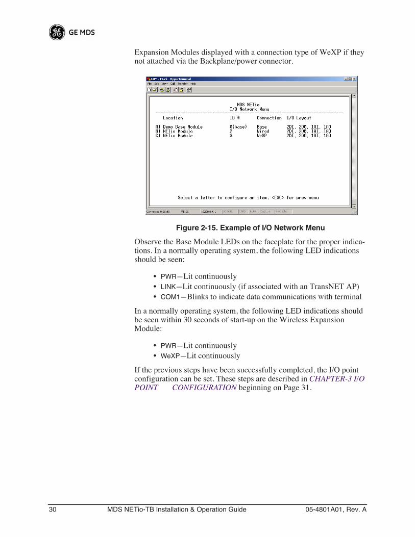
2.4.5 Module MenuThe Module Menu (Figure 2-14) is where general NETio module parameters can be viewed or set.
Quick Start Step #14:
Select B and enter the WeXP Network Address to match the address entered in the Base Module (see Section 2.3.5 above). Next, proceed to Section 2.5.
Invisible place holder
Figure 2-14. Module Menu
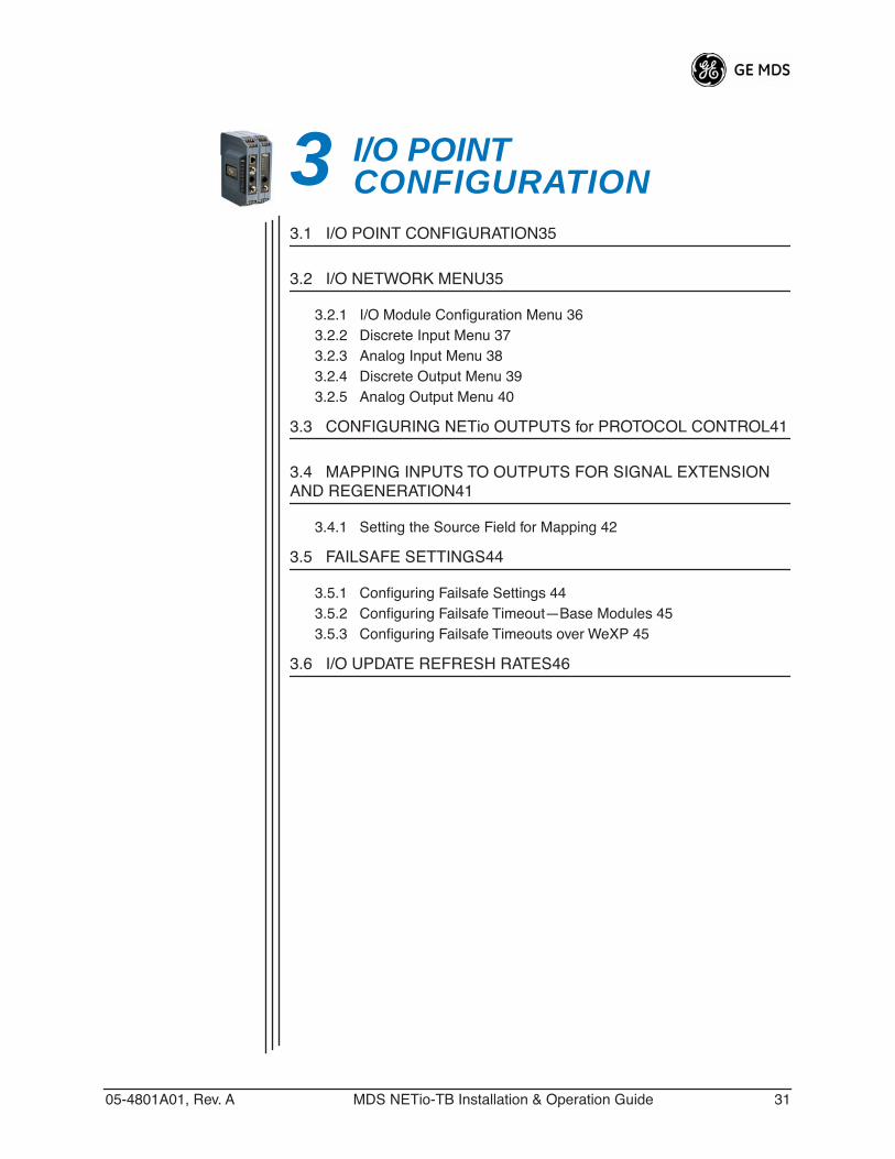
2.5 CHECK for NORMAL OPERATIONWhen all modules have been configured, you should be able to use all modules in the I/O Network Menu. Note that you will only see Wireless
30 MDS NETio-TB Installation & Operation Guide 05-4801A01, Rev. A
Expansion Modules displayed with a connection type of WeXP if they not attached via the Backplane/power connector.
Figure 2-15. Example of I/O Network Menu
Observe the Base Module LEDs on the faceplate for the proper indica-tions. In a normally operating system, the following LED indications should be seen:
• PWR—Lit continuously• LINK—Lit continuously (if associated with an TransNET AP)• COM1—Blinks to indicate data communications with terminal
In a normally operating system, the following LED indications should be seen within 30 seconds of start-up on the Wireless Expansion Module:
• PWR—Lit continuously• WeXP—Lit continuously
If the previous steps have been successfully completed, the I/O point configuration can be set. These steps are described in CHAPTER-3 I/O POINT CONFIGURATION beginning on Page 31.
05-4801A01, Rev. A MDS NETio-TB Installation & Operation Guide 31
3 I/O POINT CONFIGURATION3 .............................................................................................. Chap-ter Counter Reset 3.1 I/O POINT CONFIGURATION35
3.2 I/O NETWORK MENU35
3.2.1 I/O Module Configuration Menu 363.2.2 Discrete Input Menu 373.2.3 Analog Input Menu 383.2.4 Discrete Output Menu 393.2.5 Analog Output Menu 40
3.3 CONFIGURING NETio OUTPUTS for PROTOCOL CONTROL41
3.4 MAPPING INPUTS TO OUTPUTS FOR SIGNAL EXTENSION AND REGENERATION41
3.4.1 Setting the Source Field for Mapping 42
3.5 FAILSAFE SETTINGS44
3.5.1 Configuring Failsafe Settings 443.5.2 Configuring Failsafe Timeout—Base Modules 453.5.3 Configuring Failsafe Timeouts over WeXP 45
3.6 I/O UPDATE REFRESH RATES46

32 MDS NETio-TB Installation & Operation Guide 05-4801A01, Rev. A
05-4801A01, Rev. A MDS NETio-TB Installation & Operation Guide 33
3.1 I/O POINT CONFIGURATIONThis section describes how to configure I/O points in a NETio Unit. This process is required for each I/O signal connected to a NETio Unit. The instructions here assume that you have established a PC connection with the unit as described earlier in this manual.
This section also gives instructions for “mapping” an input to a partic-ular output. This is required in cases where an input signal connected to one NETio Module must be regenerated as an output from a different NETio Module.
Each I/O point has a unique address that corresponds to where it is located in a NETio Unit. You use this address when mapping one point to another in a Signal Extender function, or when selecting the point in a Protocol node.
A point address consists of three fields:
• Module ID—The number assigned to the NETio module.
For Expansion Modules: The Module ID is set by the user (see ASSIGNING MODULE IDs on Page 24).
• Point Number—This number references the physical termina-tion number of a particular I/O point on a NETio Module. It is automatically assigned.
Each I/O point connected to a NETio Unit has an address with the format shown below. Each field is separated by a comma:
<Module ID>,<Point Number>
3.2 I/O NETWORK MENUThe I/O Network menu shows the Base Module and any Expansion Modules (if present) connected via the Backplane/power connector or WeXP. If there are a large number of modules in the network, it will be necessary to scroll down the screen to view all entries.
I/O points are configured by selecting the module that a signal is wired to and then selecting a particular I/O point. When a wireless expansion module is selected the WeXP LED blinks to indicate that it is being accessed for configuration.
Quick Start Step #15:
Select the letter associated with the module containing the I/O point to be configured. Proceed to Section 3.2.1.
34 MDS NETio-TB Installation & Operation Guide 05-4801A01, Rev. A
Figure 3-1. Example of I/O Network Menu
3.2.1 I/O Module Configuration MenuThe I/O Module Configuration Menu is where all NETio Module-spe-cific information can be viewed or changed.
Invisible place holder
Figure 3-2. I/O Module Configuration Menu
05-4801A01, Rev. A MDS NETio-TB Installation & Operation Guide 35
Quick Start Step #16:
Select the letter associated with a specific I/O point to be configured and proceed as follows:
If a Discrete Input is selected, proceed to Section 3.2.2.
If a Discrete Output is selected, proceed to Section 3.2.4
If an Analog Input is selected, proceed to Section 3.2.3
If an Analog Output is selected, proceed to Section 3.2.5
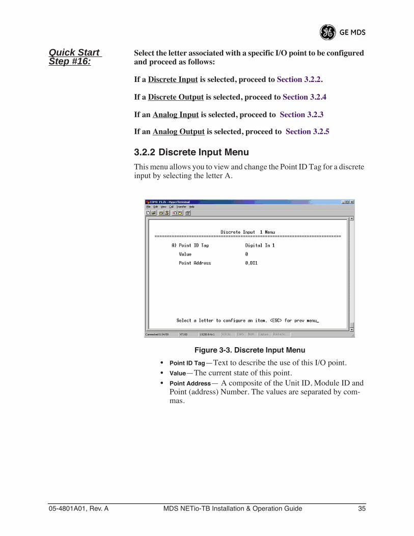
3.2.2 Discrete Input MenuThis menu allows you to view and change the Point ID Tag for a discrete input by selecting the letter A.
Figure 3-3. Discrete Input Menu
• Point ID Tag—Text to describe the use of this I/O point.• Value—The current state of this point.• Point Address— A composite of the Unit ID, Module ID and
Point (address) Number. The values are separated by com-mas.
36 MDS NETio-TB Installation & Operation Guide 05-4801A01, Rev. A
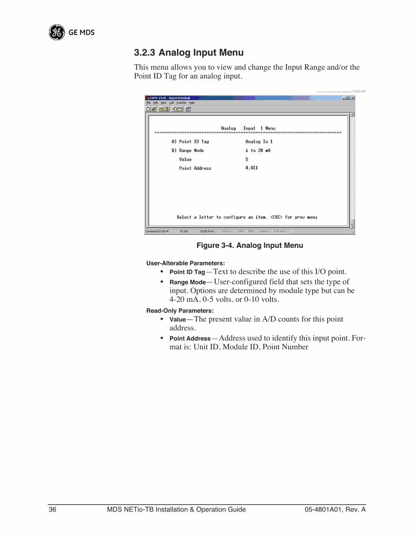
3.2.3 Analog Input MenuThis menu allows you to view and change the Input Range and/or the Point ID Tag for an analog input.
Invisible place holderThis menu allowsyou to review and revise many parameters for a analog point.
Figure 3-4. Analog Input Menu
User-Alterable Parameters:• Point ID Tag—Text to describe the use of this I/O point.• Range Mode—User-configured field that sets the type of
input. Options are determined by module type but can be 4-20 mA, 0-5 volts, or 0-10 volts.
Read-Only Parameters:• Value—The present value in A/D counts for this point
address.• Point Address—Address used to identify this input point. For-
mat is: Unit ID, Module ID, Point Number
05-4801A01, Rev. A MDS NETio-TB Installation & Operation Guide 37
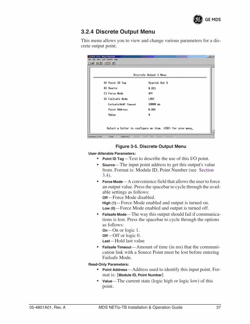
3.2.4 Discrete Output MenuThis menu allows you to view and change various parameters for a dis-crete output point.
Figure 3-5. Discrete Output Menu
User-Alterable Parameters:• Point ID Tag—Text to describe the use of this I/O point.• Source—The input point address to get this output's value
from. Format is: Module ID, Point Number (see Section 3.4).
• Force Mode—A convenience field that allows the user to force an output value. Press the spacebar to cycle through the avail-able settings as follows:Off—Force Mode disabled.High (1)—Force Mode enabled and output is turned on.Low (0)—Force Mode enabled and output is turned off.
• Failsafe Mode—The way this output should fail if communica-tions is lost. Press the spacebar to cycle through the options as follows:On—On or logic 1.Off—Off or logic 0.Last—Hold last value
• Failsafe Timeout—Amount of time (in ms) that the communi-cation link with a Source Point must be lost before entering Failsafe Mode.
Read-Only Parameters:• Point Address—Address used to identify this input point. For-
mat is: [Module ID, Point Number]• Value—The current state (logic high or logic low) of this
point.
38 MDS NETio-TB Installation & Operation Guide 05-4801A01, Rev. A
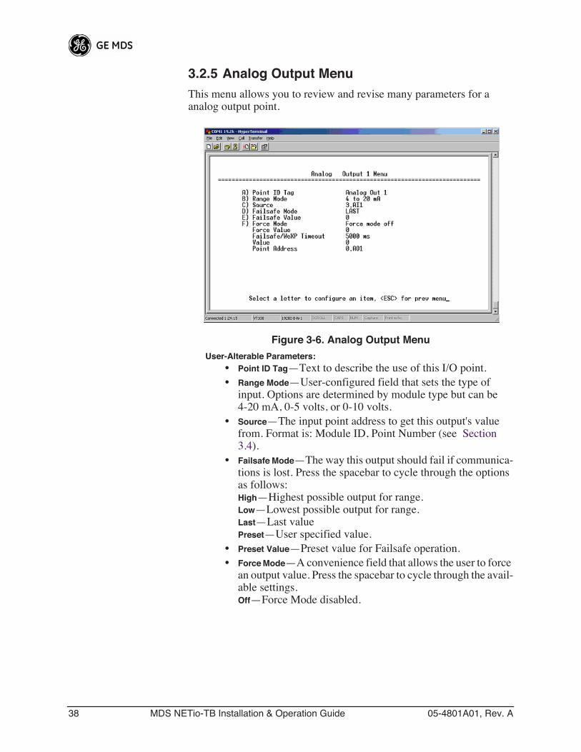
3.2.5 Analog Output MenuThis menu allows you to review and revise many parameters for a analog output point.
Figure 3-6. Analog Output Menu
User-Alterable Parameters:• Point ID Tag—Text to describe the use of this I/O point.• Range Mode—User-configured field that sets the type of
input. Options are determined by module type but can be 4-20 mA, 0-5 volts, or 0-10 volts.
• Source—The input point address to get this output's value from. Format is: Module ID, Point Number (see Section 3.4).
• Failsafe Mode—The way this output should fail if communica-tions is lost. Press the spacebar to cycle through the options as follows:High—Highest possible output for range.Low—Lowest possible output for range.Last—Last valuePreset—User specified value.
• Preset Value—Preset value for Failsafe operation.• Force Mode—A convenience field that allows the user to force
an output value. Press the spacebar to cycle through the avail-able settings.Off—Force Mode disabled.
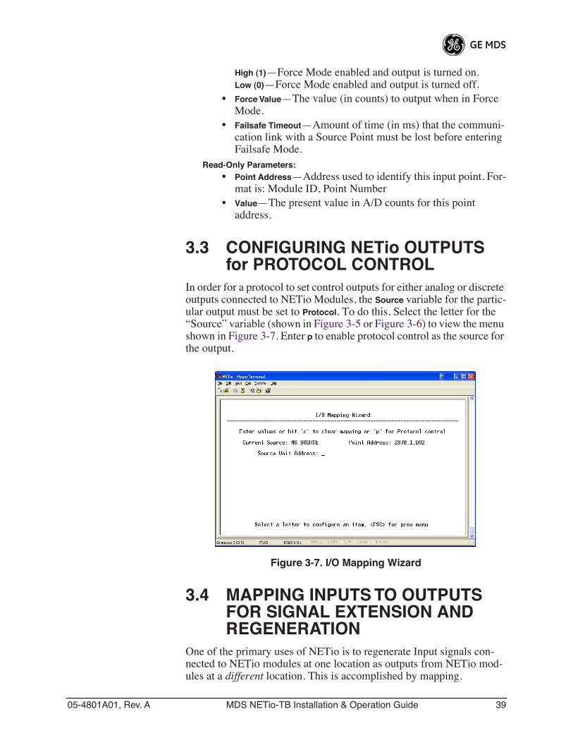
05-4801A01, Rev. A MDS NETio-TB Installation & Operation Guide 39
High (1)—Force Mode enabled and output is turned on.Low (0)—Force Mode enabled and output is turned off.
• Force Value—The value (in counts) to output when in Force Mode.
• Failsafe Timeout—Amount of time (in ms) that the communi-cation link with a Source Point must be lost before entering Failsafe Mode.
Read-Only Parameters:• Point Address—Address used to identify this input point. For-
mat is: Module ID, Point Number• Value—The present value in A/D counts for this point
address.
3.3 CONFIGURING NETio OUTPUTS for PROTOCOL CONTROL
In order for a protocol to set control outputs for either analog or discrete outputs connected to NETio Modules, the Source variable for the partic-ular output must be set to Protocol. To do this, Select the letter for the “Source” variable (shown in Figure 3-5 or Figure 3-6) to view the menu shown in Figure 3-7. Enter p to enable protocol control as the source for the output.
Invisible place holder
Figure 3-7. I/O Mapping Wizard
3.4 MAPPING INPUTS TO OUTPUTS FOR SIGNAL EXTENSION AND REGENERATION
One of the primary uses of NETio is to regenerate Input signals con-nected to NETio modules at one location as outputs from NETio mod-ules at a different location. This is accomplished by mapping.
40 MDS NETio-TB Installation & Operation Guide 05-4801A01, Rev. A
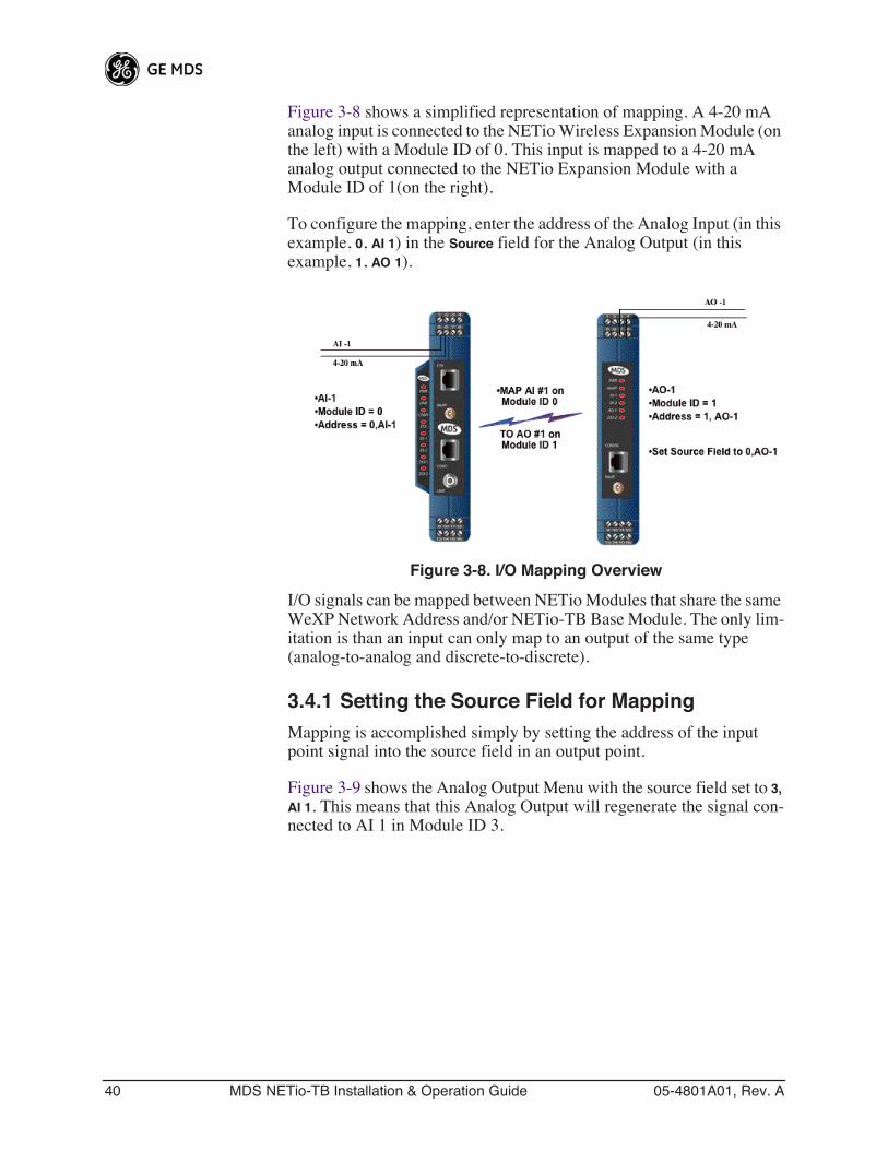
Figure 3-8 shows a simplified representation of mapping. A 4-20 mA analog input is connected to the NETio Wireless Expansion Module (on the left) with a Module ID of 0. This input is mapped to a 4-20 mA analog output connected to the NETio Expansion Module with a Module ID of 1(on the right).
To configure the mapping, enter the address of the Analog Input (in this example, 0, AI 1) in the Source field for the Analog Output (in this example, 1, AO 1).
Invisible place holder
Figure 3-8. I/O Mapping Overview
I/O signals can be mapped between NETio Modules that share the same WeXP Network Address and/or NETio-TB Base Module. The only lim-itation is than an input can only map to an output of the same type (analog-to-analog and discrete-to-discrete).
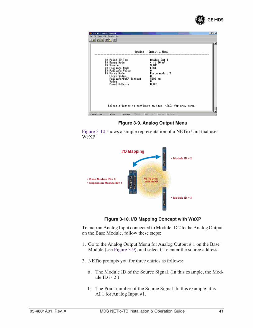
3.4.1 Setting the Source Field for MappingMapping is accomplished simply by setting the address of the input point signal into the source field in an output point.
Figure 3-9 shows the Analog Output Menu with the source field set to 3, AI 1. This means that this Analog Output will regenerate the signal con-nected to AI 1 in Module ID 3.
05-4801A01, Rev. A MDS NETio-TB Installation & Operation Guide 41
Invisible place holder
Figure 3-9. Analog Output Menu
Figure 3-10 shows a simple representation of a NETio Unit that uses WeXP.
Invisible place holder
Figure 3-10. I/O Mapping Concept with WeXP
To map an Analog Input connected to Module ID 2 to the Analog Output on the Base Module, follow these steps:
1. Go to the Analog Output Menu for Analog Output # 1 on the Base Module (see Figure 3-9), and select C to enter the source address.
2. NETio prompts you for three entries as follows:
a. The Module ID of the Source Signal. (In this example, the Mod-ule ID is 2.)
b. The Point number of the Source Signal. In this example, it is AI 1 for Analog Input #1.
42 MDS NETio-TB Installation & Operation Guide 05-4801A01, Rev. A
Note that pressing the spacebar will cycle through two AI choices for Analog and six DI choices for Discretes. This is due to the maximum capacity for Analog inputs and Discrete inputs on any NETio Module.
3.5 FAILSAFE SETTINGSNETio Failsafe settings allow configuration of the output signal’s behavior in the event of loss of communication. By definition, any output signal a NETio module has been configured to generate relies on one or more of these communication modes:
1. WeXP—Wireless communication between Wireless Expansion Modules and a NETio Base Module within a NETio Unit.
2. NETio Backplane—Wired communication between a Base Module and Expansion Modules using the NETio Backplane/power Connec-tors.
When any one or more of these communication modes fails for a con-figurable period of time, an output will enter Failsafe mode and generate the Failsafe value selected by the user. The user can accept the factory settings or modify them, but Failsafe behavior is always activated for an output signal.
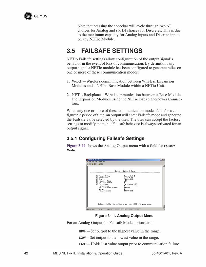
3.5.1 Configuring Failsafe SettingsFigure 3-11 shows the Analog Output menu with a field for Failsafe Mode.
Invisible place holder
Figure 3-11. Analog Output Menu
For an Analog Output the Failsafe Mode options are:
HIGH—Set output to the highest value in the range.
LOW—Set output to the lowest value in the range.
LAST—Holds last value output prior to communication failure.
05-4801A01, Rev. A MDS NETio-TB Installation & Operation Guide 43
PRESET—Generate a preset value. When this option is selected, a variable field is presented where you can enter the preset value.
For a Discrete Output the Failsafe Mode options are:
HIGH—Output is set to logic 1.Continued...
LOW—Output is set to logic 0.
LAST—Output last state prior to communication failure.
3.5.2 Configuring Failsafe Timeout—Base ModulesFigure 3-11 also shows a read-only field for Failsafe/WeXP Timeout. This field defines the timeout period in milliseconds (ms). The Failsafe Tim-eout is dictated by the WeXP timeout described in Configuring Failsafe Timeouts over WeXP below.
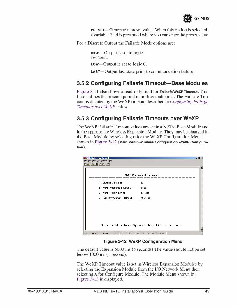
3.5.3 Configuring Failsafe Timeouts over WeXPThe WeXP Failsafe Timeout values are set in a NETio Base Module and in the appropriate Wireless Expansion Module. They may be changed in the Base Module by selecting C for the WeXP Configuration Menu shown in Figure 3-12 (Main Menu>Wireless Configuration>WeXP Configura-tion).
Invisible place holder
Figure 3-12. WeXP Configuration Menu
The default value is 5000 ms (5 seconds) The value should not be set below 1000 ms (1 second).
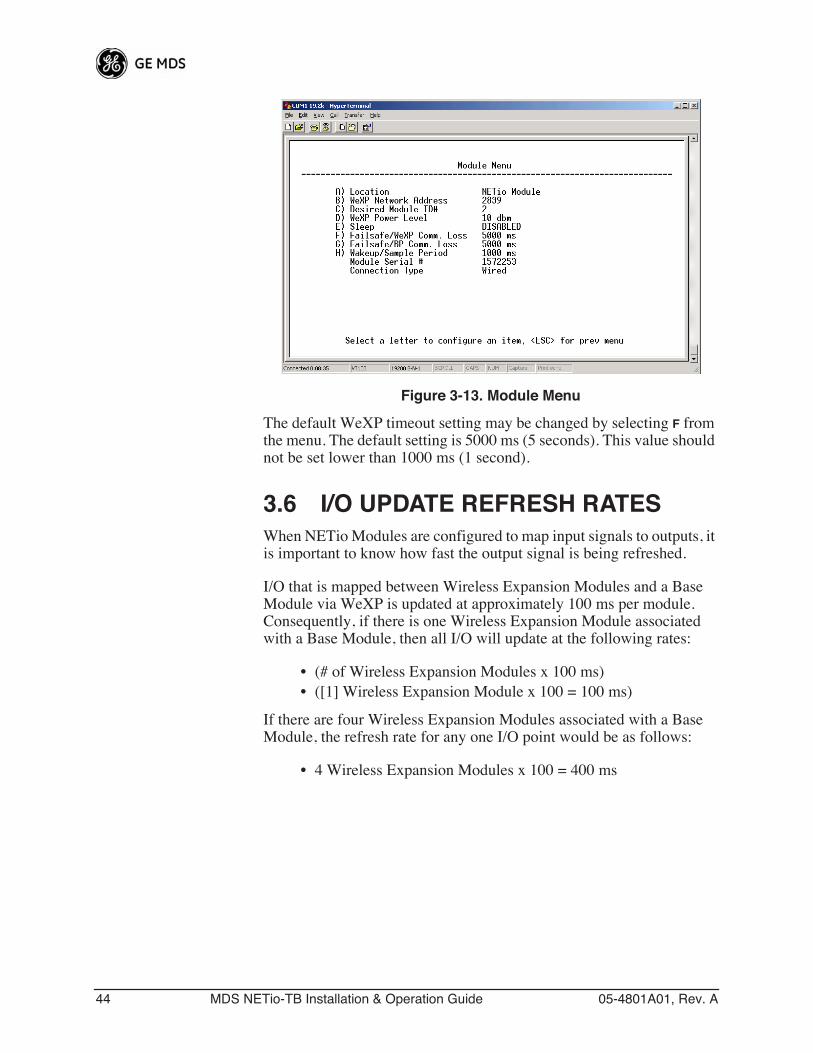
The WeXP Timeout value is set in Wireless Expansion Modules by selecting the Expansion Module from the I/O Network Menu then selecting A for Configure Module. The Module Menu shown in Figure 3-13 is displayed.
44 MDS NETio-TB Installation & Operation Guide 05-4801A01, Rev. A
Invisible place holder
Figure 3-13. Module Menu
The default WeXP timeout setting may be changed by selecting F from the menu. The default setting is 5000 ms (5 seconds). This value should not be set lower than 1000 ms (1 second).
3.6 I/O UPDATE REFRESH RATESWhen NETio Modules are configured to map input signals to outputs, it is important to know how fast the output signal is being refreshed.
I/O that is mapped between Wireless Expansion Modules and a Base Module via WeXP is updated at approximately 100 ms per module. Consequently, if there is one Wireless Expansion Module associated with a Base Module, then all I/O will update at the following rates:
• (# of Wireless Expansion Modules x 100 ms)• ([1] Wireless Expansion Module x 100 = 100 ms)
If there are four Wireless Expansion Modules associated with a Base Module, the refresh rate for any one I/O point would be as follows:
• 4 Wireless Expansion Modules x 100 = 400 ms
05-4801A01, Rev. A MDS NETio-TB Installation & Operation Guide 45
4 WIRING & TERMINATIONS
4 Chapter Counter Reset 4.1 I/O & POWER CONNECTIONS ........................................... 67
4.1.1 Module Dimensions ............................................................... 674.1.2 I/O Configurations ................................................................. 67
4.2 I/O POINTS WIRING & TERMINATION................................ 68
4.2.1 Analog Input Wiring (Current Signals) ................................... 684.2.2 Analog Output Wiring (Current Signals) ................................ 694.2.3 Analog Input Wiring (Voltage Signals) ................................... 694.2.4 Discrete Points Wiring ........................................................... 704.2.5 Module Wiring Diagrams ....................................................... 70
46 MDS NETio-TB Installation & Operation Guide 05-4801A01, Rev. A
05-4801A01, Rev. A MDS NETio-TB Installation & Operation Guide 47
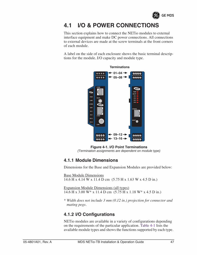
4.1 I/O & POWER CONNECTIONSThis section explains how to connect the NETio modules to external interface equipment and make DC power connections. All connections to external devices are made at the screw terminals at the front corners of each module.
A label on the side of each enclosure shows the basic terminal descrip-tions for the module, I/O capacity and module type.
Invisible place holder
Figure 4-1. I/O Point Terminations(Termination assignments are dependent on module type)
4.1.1 Module DimensionsDimensions for the Base and Expansion Modules are provided below:
Base Module Dimensions 14.6 H x 4.14 W x 11.4 D cm (5.75 H x 1.63 W x 4.5 D in.)
Expansion Module Dimensions (all types)14.6 H x 3.00 W* x 11.4 D cm (5.75 H x 1.18 W* x 4.5 D in.)
* Width does not include 3 mm (0.12 in.) projection for connector and mating pegs.
4.1.2 I/O ConfigurationsNETio modules are available in a variety of configurations depending on the requirements of the particular application. Table 4-1 lists the available module types and shows the functions supported by each type.
01–0405–08
Terminations
09–1213–16
PWR
WeXP
DI-1
DI-2
DI-3
DI-4
WeXP
CONFIG
LINK
WeXP
COM2
COM1
PWR
LINK
COM1
ETH
DI-1
DI-2
DO-1
DO-2
48 MDS NETio-TB Installation & Operation Guide 05-4801A01, Rev. A
In addition, references are also given to show where detailed wiring information may be found in this manual.
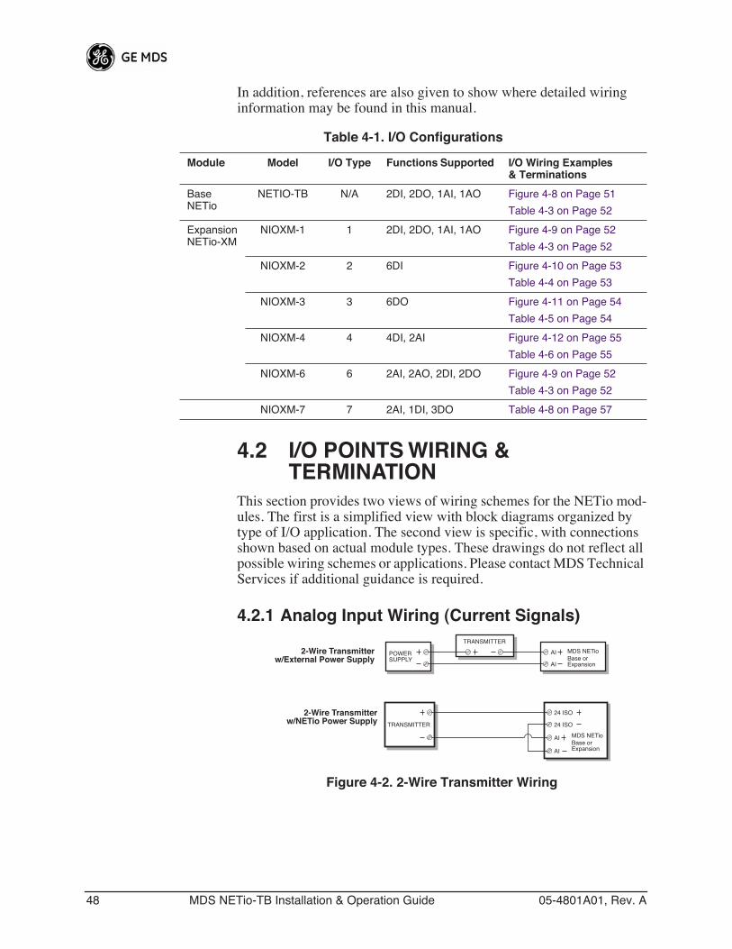
4.2 I/O POINTS WIRING & TERMINATION
This section provides two views of wiring schemes for the NETio mod-ules. The first is a simplified view with block diagrams organized by type of I/O application. The second view is specific, with connections shown based on actual module types. These drawings do not reflect all possible wiring schemes or applications. Please contact MDS Technical Services if additional guidance is required.
4.2.1 Analog Input Wiring (Current Signals)
Figure 4-2. 2-Wire Transmitter Wiring
Table 4-1. I/O Configurations
Module Model I/O Type Functions Supported I/O Wiring Examples& Terminations
BaseNETio
NETIO-TB N/A 2DI, 2DO, 1AI, 1AO Figure 4-8 on Page 51
Table 4-3 on Page 52
ExpansionNETio-XM
NIOXM-1 1 2DI, 2DO, 1AI, 1AO Figure 4-9 on Page 52
Table 4-3 on Page 52
NIOXM-2 2 6DI Figure 4-10 on Page 53
Table 4-4 on Page 53
NIOXM-3 3 6DO Figure 4-11 on Page 54
Table 4-5 on Page 54
NIOXM-4 4 4DI, 2AI Figure 4-12 on Page 55
Table 4-6 on Page 55
NIOXM-6 6 2AI, 2AO, 2DI, 2DO Figure 4-9 on Page 52
Table 4-3 on Page 52
NIOXM-7 7 2AI, 1DI, 3DO Table 4-8 on Page 57
TRANSMITTER
24 ISO
24 ISO
MDS NETioBase orExpansion
2-Wire Transmitterw/NETio Power Supply
AI
AI
POWERSUPPLY
TRANSMITTER
AI
AI
MDS NETioBase orExpansion
2-Wire Transmitterw/External Power Supply
05-4801A01, Rev. A MDS NETio-TB Installation & Operation Guide 49
Invisible place holder
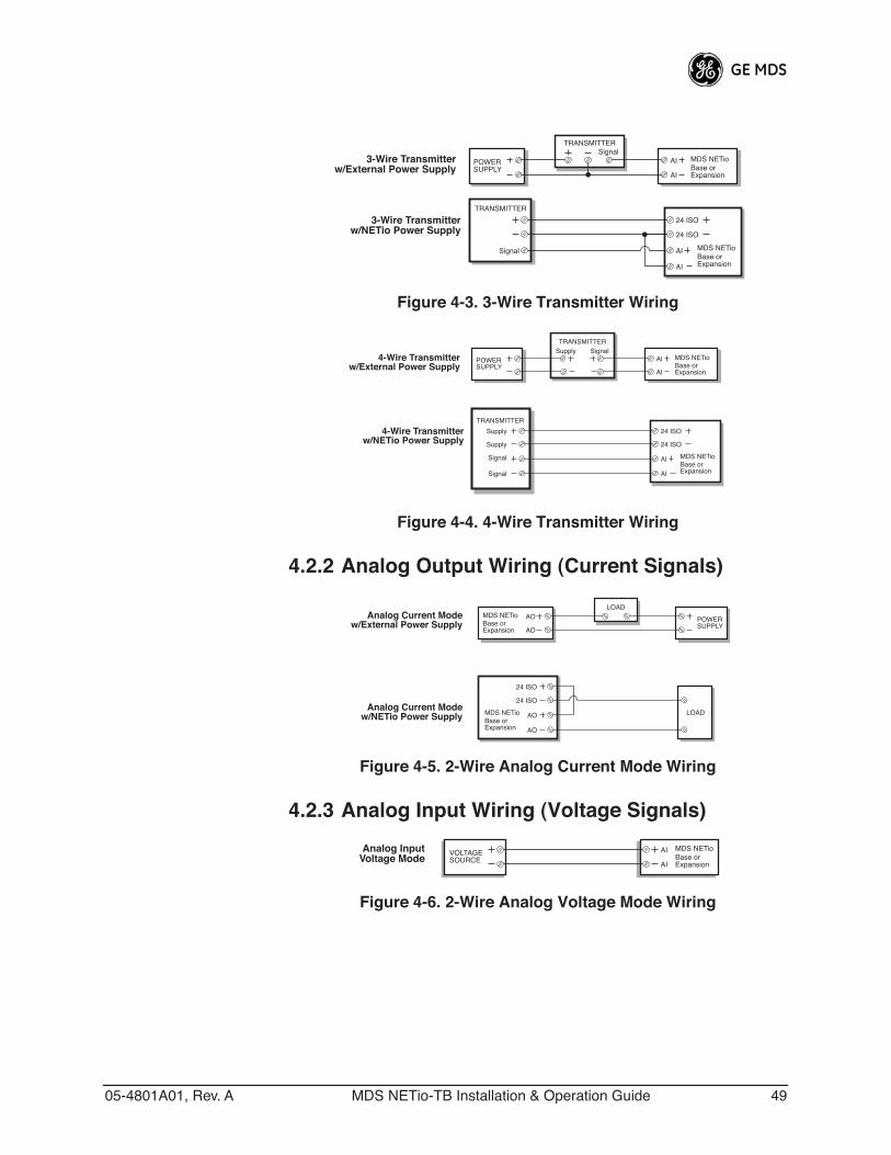
Figure 4-3. 3-Wire Transmitter WiringInvisible place holder
Figure 4-4. 4-Wire Transmitter Wiring
4.2.2 Analog Output Wiring (Current Signals)
Figure 4-5. 2-Wire Analog Current Mode Wiring
4.2.3 Analog Input Wiring (Voltage Signals)
Figure 4-6. 2-Wire Analog Voltage Mode Wiring
POWERSUPPLY
TRANSMITTER
AI
AI
MDS NETioBase orExpansion
3-Wire Transmitterw/External Power Supply
Signal
TRANSMITTER
24 ISO
24 ISO
MDS NETioBase orExpansion
3-Wire Transmitterw/NETio Power Supply
AI
AI
Signal
POWERSUPPLY
TRANSMITTER
AI
AI
MDS NETioBase orExpansion
4-Wire Transmitterw/External Power Supply
SignalSupply
TRANSMITTER
24 ISO
24 ISO
MDS NETioBase orExpansion
4-Wire Transmitterw/NETio Power Supply
AI
AI
Signal
Signal
Supply
Supply
Analog Current Modew/NETio Power Supply
Analog Current Modew/External Power Supply
LOADMDS NETioBase orExpansion
24 ISO
24 ISO
AO
AO
POWERSUPPLY
LOADMDS NETioBase orExpansion
AO
AO
Analog InputVoltage Mode
VOLTAGESOURCE
MDS NETioBase orExpansion
AI
AI
50 MDS NETio-TB Installation & Operation Guide 05-4801A01, Rev. A
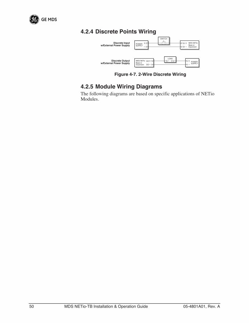
4.2.4 Discrete Points Wiring
Figure 4-7. 2-Wire Discrete Wiring
4.2.5 Module Wiring DiagramsThe following diagrams are based on specific applications of NETio Modules.
Discrete Outputw/External Power Supply
POWERSUPPLY
LOADMDS NETioBase orExpansion
DO
DO
Discrete Inputw/External Power Supply
SWITCH
DI
DI
MDS NETioBase orExpansion
POWERSUPPLY
05-4801A01, Rev. A MDS NETio-TB Installation & Operation Guide 51
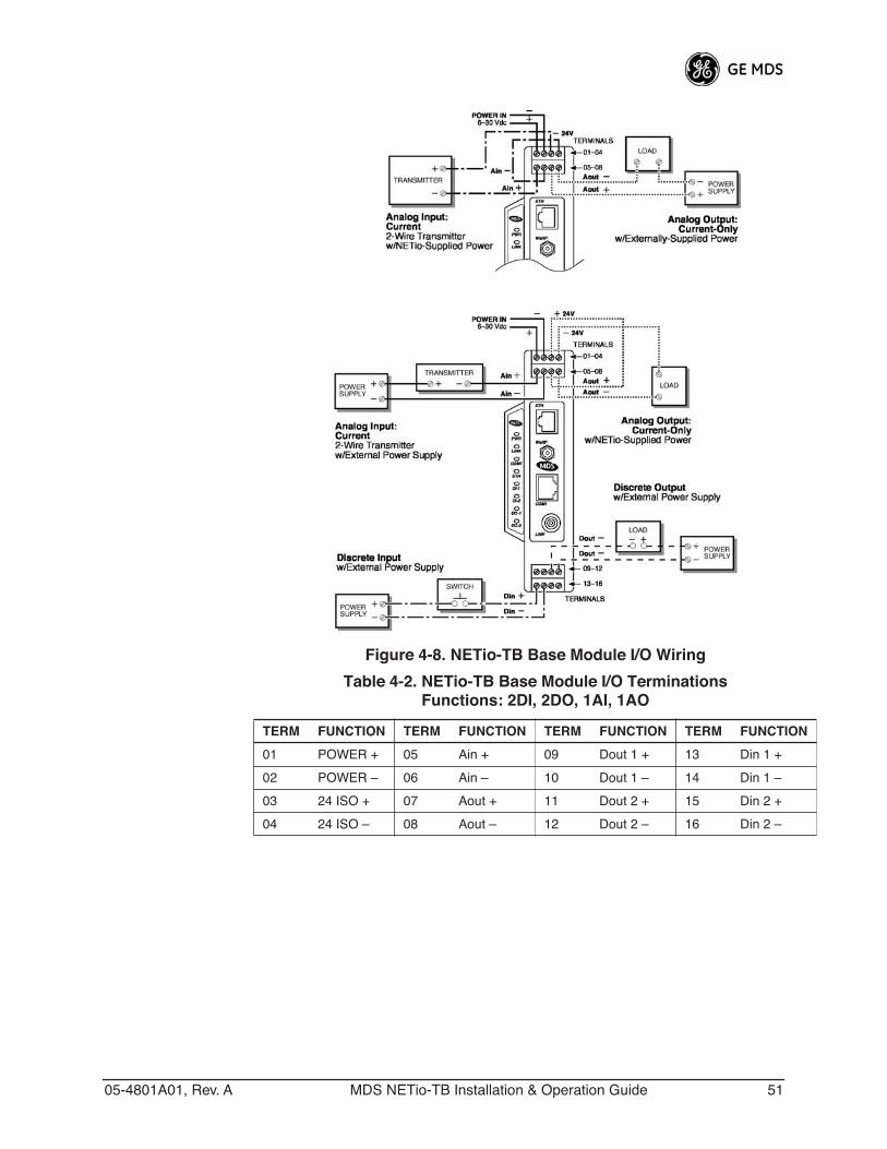
Invisible place holder
Figure 4-8. NETio-TB Base Module I/O Wiring Table 4-2. NETio-TB Base Module I/O Terminations
Functions: 2DI, 2DO, 1AI, 1AO
TERM FUNCTION TERM FUNCTION TERM FUNCTION TERM FUNCTION
01 POWER + 05 Ain + 09 Dout 1 + 13 Din 1 +
02 POWER – 06 Ain – 10 Dout 1 – 14 Din 1 –
03 24 ISO + 07 Aout + 11 Dout 2 + 15 Din 2 +
04 24 ISO – 08 Aout – 12 Dout 2 – 16 Din 2 –
52 MDS NETio-TB Installation & Operation Guide 05-4801A01, Rev. A
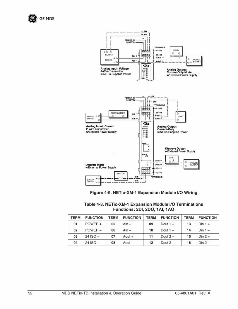
Invisible place holder
Figure 4-9. NETio-XM-1 Expansion Module I/O Wiring
Table 4-3. NETio-XM-1 Expansion Module I/O TerminationsFunctions: 2DI, 2DO, 1AI, 1AO
TERM FUNCTION TERM FUNCTION TERM FUNCTION TERM FUNCTION
01 POWER + 05 Ain + 09 Dout 1 + 13 Din 1 +
02 POWER – 06 Ain – 10 Dout 1 – 14 Din 1 –
03 24 ISO + 07 Aout + 11 Dout 2 + 15 Din 2 +
04 24 ISO – 08 Aout – 12 Dout 2 – 16 Din 2 –
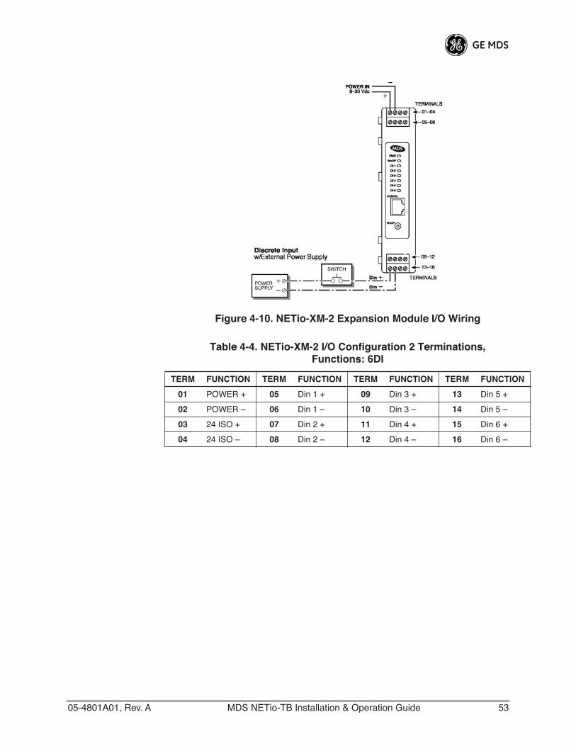
05-4801A01, Rev. A MDS NETio-TB Installation & Operation Guide 53
Figure 4-10. NETio-XM-2 Expansion Module I/O Wiring
Table 4-4. NETio-XM-2 I/O Configuration 2 Terminations,Functions: 6DI
TERM FUNCTION TERM FUNCTION TERM FUNCTION TERM FUNCTION
01 POWER + 05 Din 1 + 09 Din 3 + 13 Din 5 +
02 POWER – 06 Din 1 – 10 Din 3 – 14 Din 5 –
03 24 ISO + 07 Din 2 + 11 Din 4 + 15 Din 6 +
04 24 ISO – 08 Din 2 – 12 Din 4 – 16 Din 6 –
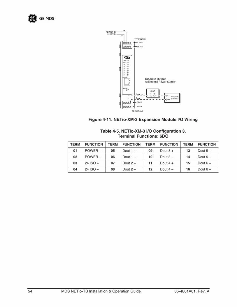
54 MDS NETio-TB Installation & Operation Guide 05-4801A01, Rev. A
Invisible place holder
Figure 4-11. NETio-XM-3 Expansion Module I/O Wiring
WeXP
CONFIG
PWR
WeXP
DO-1
DO-2
DO-3
DO-4
DO-5
DO-6
09–12
13–16
TERMINALS
LOAD
POWERSUPPLY
Dout
Dout
01–04
05–08
TERMINALS
POWER IN6–30 Vdc
Discrete Outputw/External Power Supply
Table 4-5. NETio-XM-3 I/O Configuration 3,Terminal Functions: 6DO
TERM FUNCTION TERM FUNCTION TERM FUNCTION TERM FUNCTION
01 POWER + 05 Dout 1 + 09 Dout 3 + 13 Dout 5 +
02 POWER – 06 Dout 1 – 10 Dout 3 – 14 Dout 5 –
03 24 ISO + 07 Dout 2 + 11 Dout 4 + 15 Dout 6 +
04 24 ISO – 08 Dout 2 – 12 Dout 4 – 16 Dout 6 –
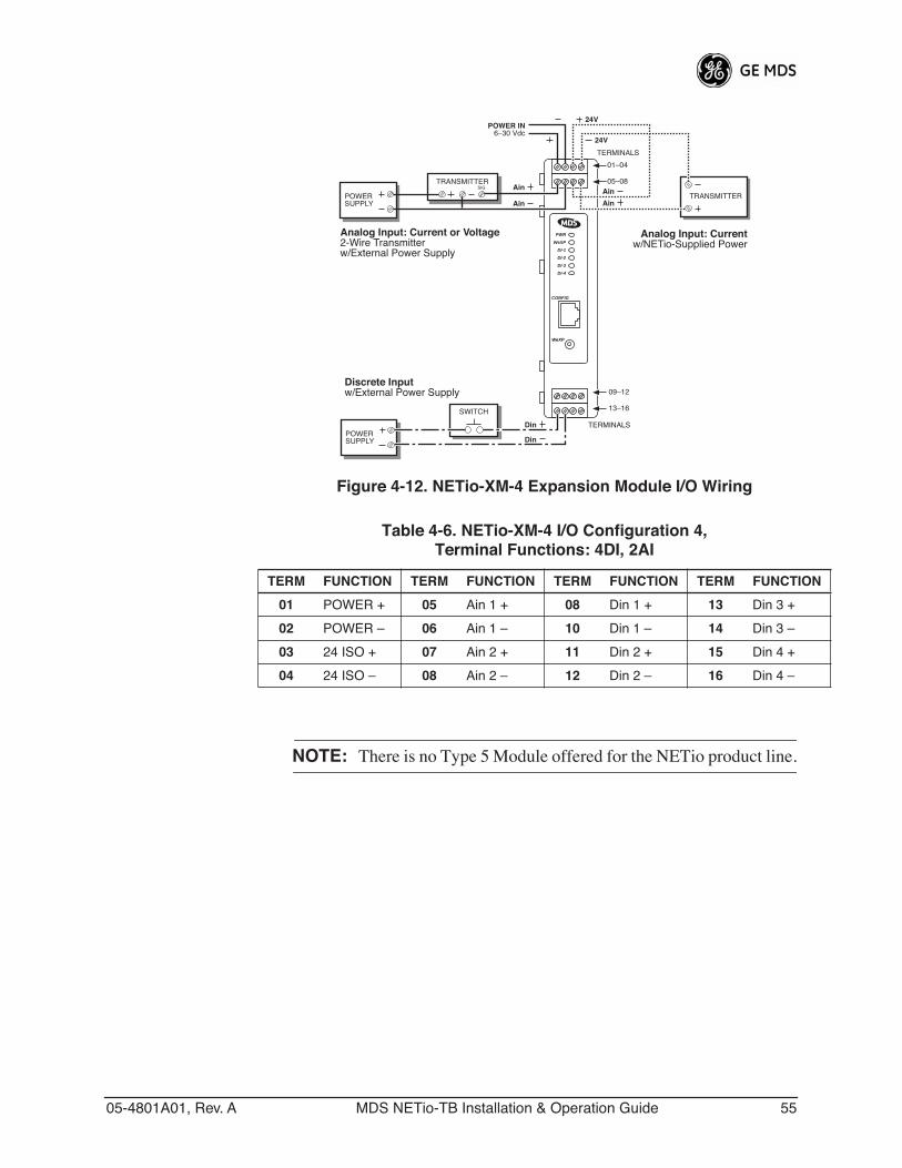
05-4801A01, Rev. A MDS NETio-TB Installation & Operation Guide 55
Invisible place holder
Figure 4-12. NETio-XM-4 Expansion Module I/O Wiring
NOTE: There is no Type 5 Module offered for the NETio product line.
WeXP
CONFIG
PWR
WeXP
DI-1
DI-2
DI-3
DI-4
01–04
05–08
TERMINALS
POWERSUPPLY
TRANSMITTER
Analog Input: Current or Voltage2-Wire Transmitterw/External Power Supply
Ain
Ain
TERMINALS
Ain
Analog Input: Currentw/NETio-Supplied Power
24V
24V
TRANSMITTERAin
Discrete Inputw/External Power Supply
SWITCH
POWERSUPPLY
Din
Din
09–12
13–16
SIG
POWER IN6–30 Vdc
Table 4-6. NETio-XM-4 I/O Configuration 4,Terminal Functions: 4DI, 2AI
TERM FUNCTION TERM FUNCTION TERM FUNCTION TERM FUNCTION
01 POWER + 05 Ain 1 + 08 Din 1 + 13 Din 3 +
02 POWER – 06 Ain 1 – 10 Din 1 – 14 Din 3 –
03 24 ISO + 07 Ain 2 + 11 Din 2 + 15 Din 4 +
04 24 ISO – 08 Ain 2 – 12 Din 2 – 16 Din 4 –
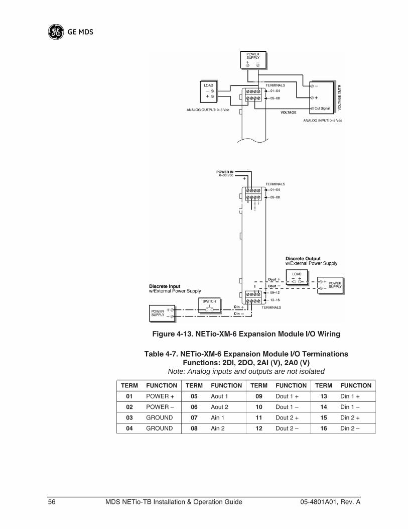
56 MDS NETio-TB Installation & Operation Guide 05-4801A01, Rev. A
Invisible place holder
Figure 4-13. NETio-XM-6 Expansion Module I/O Wiring
Table 4-7. NETio-XM-6 Expansion Module I/O TerminationsFunctions: 2DI, 2DO, 2AI (V), 2A0 (V)
Note: Analog inputs and outputs are not isolated
TERM FUNCTION TERM FUNCTION TERM FUNCTION TERM FUNCTION
01 POWER + 05 Aout 1 09 Dout 1 + 13 Din 1 +
02 POWER – 06 Aout 2 10 Dout 1 – 14 Din 1 –
03 GROUND 07 Ain 1 11 Dout 2 + 15 Din 2 +
04 GROUND 08 Ain 2 12 Dout 2 – 16 Din 2 –
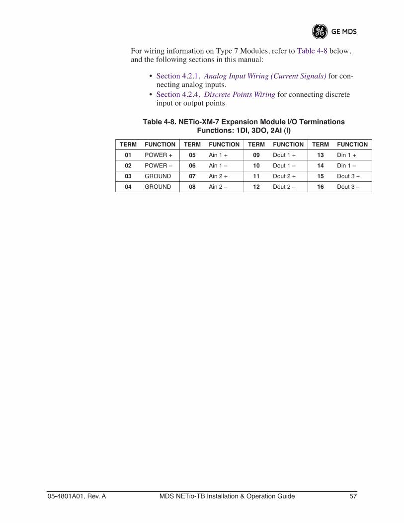
05-4801A01, Rev. A MDS NETio-TB Installation & Operation Guide 57
For wiring information on Type 7 Modules, refer to Table 4-8 below, and the following sections in this manual:
• Section 4.2.1, Analog Input Wiring (Current Signals) for con-necting analog inputs.
• Section 4.2.4, Discrete Points Wiring for connecting discrete input or output points
Table 4-8. NETio-XM-7 Expansion Module I/O TerminationsFunctions: 1DI, 3DO, 2AI (I)
TERM FUNCTION TERM FUNCTION TERM FUNCTION TERM FUNCTION
01 POWER + 05 Ain 1 + 09 Dout 1 + 13 Din 1 +
02 POWER – 06 Ain 1 – 10 Dout 1 – 14 Din 1 –
03 GROUND 07 Ain 2 + 11 Dout 2 + 15 Dout 3 +
04 GROUND 08 Ain 2 – 12 Dout 2 – 16 Dout 3 –

58 MDS NETio-TB Installation & Operation Guide 05-4801A01, Rev. A
05-4801A01, Rev. A MDS NETio-TB Installation & Operation Guide 59
5 CONFIGURING THE SERIAL PORTS
5 Chapter Counter Reset Serial Port .................................... 815.1.1 Configuring the NETio Serial Port ......................................... 815.1.2 Configuring the IP Ethernet Port ........................................... 835.2 Configuring COM2 Payload Port..................................................XX

60 MDS NETio-TB Installation & Operation Guide 05-4801A01, Rev. A
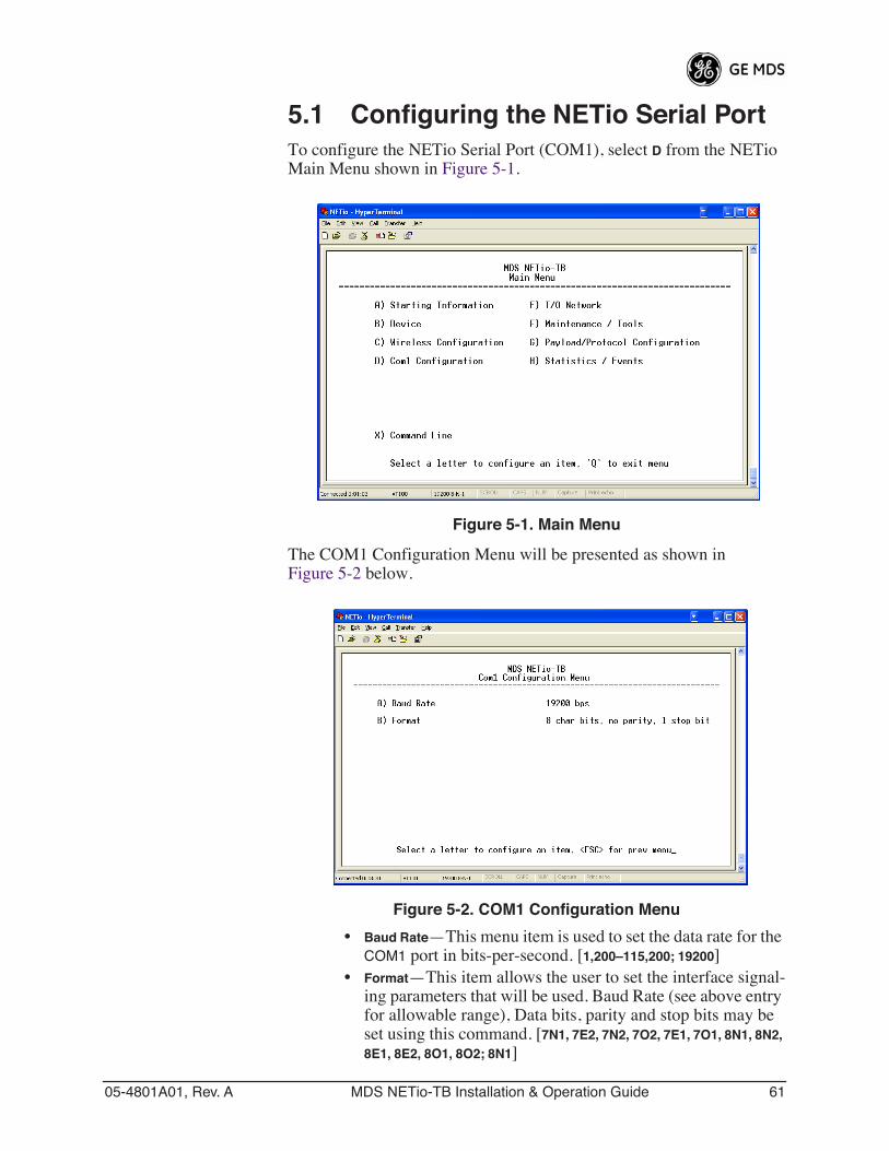
05-4801A01, Rev. A MDS NETio-TB Installation & Operation Guide 61
5.1 Configuring the NETio Serial PortTo configure the NETio Serial Port (COM1), select D from the NETio Main Menu shown in Figure 5-1.
Invisible place holder
Figure 5-1. Main Menu
The COM1 Configuration Menu will be presented as shown in Figure 5-2 below.
Invisible place holder
Figure 5-2. COM1 Configuration Menu
• Baud Rate—This menu item is used to set the data rate for the COM1 port in bits-per-second. [1,200–115,200; 19200]
• Format—This item allows the user to set the interface signal-ing parameters that will be used. Baud Rate (see above entry for allowable range), Data bits, parity and stop bits may be set using this command. [7N1, 7E2, 7N2, 7O2, 7E1, 7O1, 8N1, 8N2, 8E1, 8E2, 8O1, 8O2; 8N1]
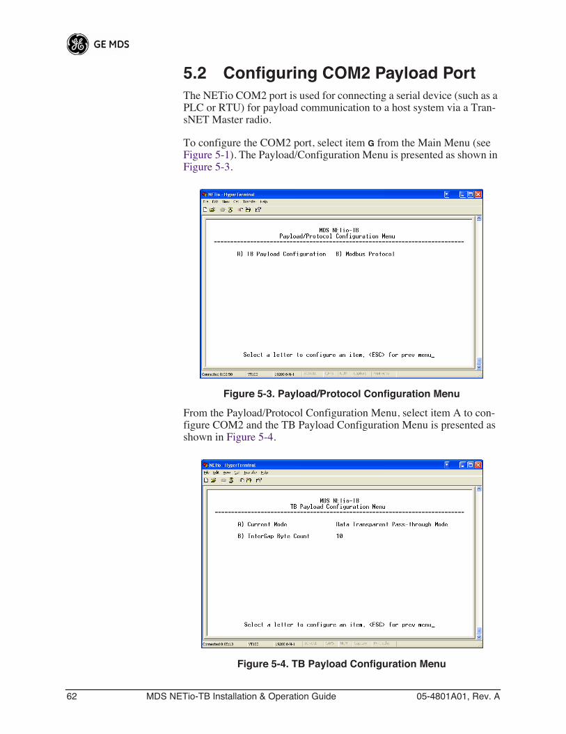
62 MDS NETio-TB Installation & Operation Guide 05-4801A01, Rev. A
5.2 Configuring COM2 Payload PortThe NETio COM2 port is used for connecting a serial device (such as a PLC or RTU) for payload communication to a host system via a Tran-sNET Master radio.
To configure the COM2 port, select item G from the Main Menu (see Figure 5-1). The Payload/Configuration Menu is presented as shown in Figure 5-3.
Invisible place holder
Figure 5-3. Payload/Protocol Configuration Menu
From the Payload/Protocol Configuration Menu, select item A to con-figure COM2 and the TB Payload Configuration Menu is presented as shown in Figure 5-4.
Invisible place holder
Figure 5-4. TB Payload Configuration Menu
05-4801A01, Rev. A MDS NETio-TB Installation & Operation Guide 63
Current Mode—Shows the mode the COM2 port is currently in. Use the spacebar to toggle between Transparent Data Mode and Protocol Local Master Mode.
InterGap Byte Count—Sets the number of bytes times that signify the end of a message.
NOTE: Setting Protocol Local Master tells NETio to process amessage locally. It will not be transmitted over the air.

64 MDS NETio-TB Installation & Operation Guide 05-4801A01, Rev. A
05-4801A01, Rev. A MDS NETio-TB Installation & Operation Guide 65
6 PROTOCOLS
6 Chapter Counter Reset Paragraph6.1 CONFIGURING MODBUS OPERATION.............................. 87

66 MDS NETio-TB Installation & Operation Guide 05-4801A01, Rev. A
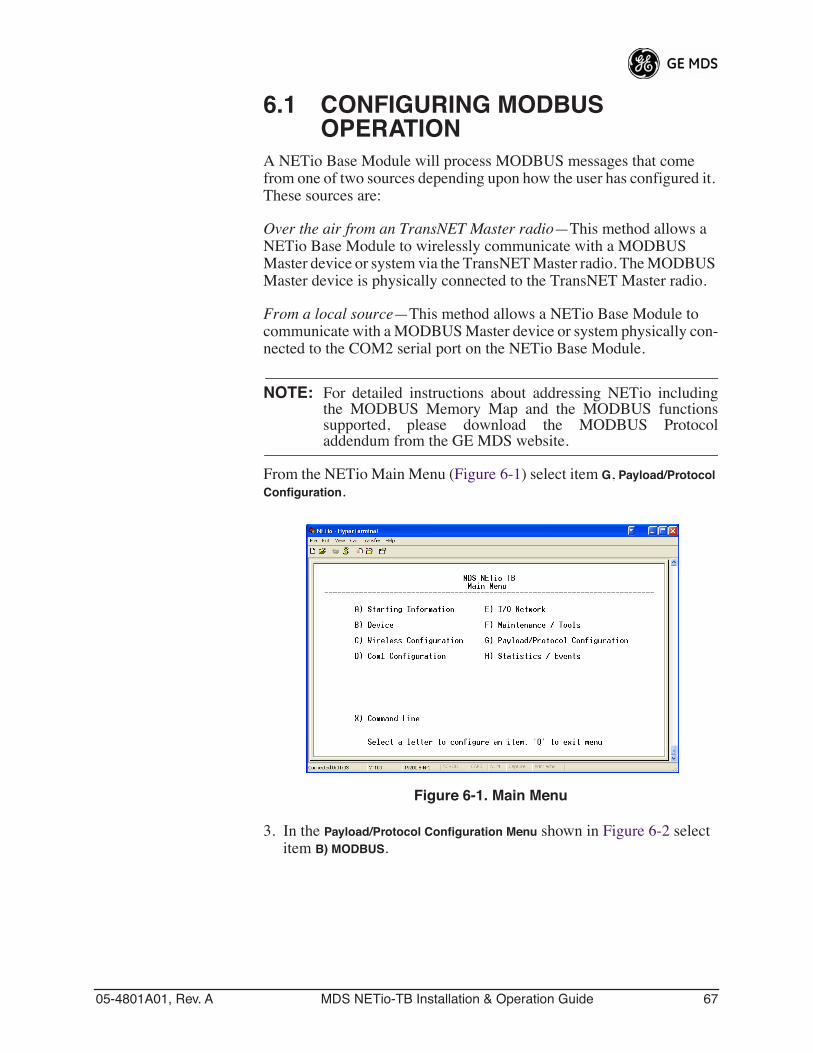
05-4801A01, Rev. A MDS NETio-TB Installation & Operation Guide 67
6.1 CONFIGURING MODBUS OPERATION
A NETio Base Module will process MODBUS messages that come from one of two sources depending upon how the user has configured it. These sources are:
Over the air from an TransNET Master radio—This method allows a NETio Base Module to wirelessly communicate with a MODBUS Master device or system via the TransNET Master radio. The MODBUS Master device is physically connected to the TransNET Master radio.
From a local source—This method allows a NETio Base Module to communicate with a MODBUS Master device or system physically con-nected to the COM2 serial port on the NETio Base Module.
NOTE: For detailed instructions about addressing NETio includingthe MODBUS Memory Map and the MODBUS functionssupported, please download the MODBUS Protocoladdendum from the GE MDS website.
From the NETio Main Menu (Figure 6-1) select item G, Payload/Protocol Configuration.
Invisible place holder
Figure 6-1. Main Menu
3. In the Payload/Protocol Configuration Menu shown in Figure 6-2 select item B) MODBUS.
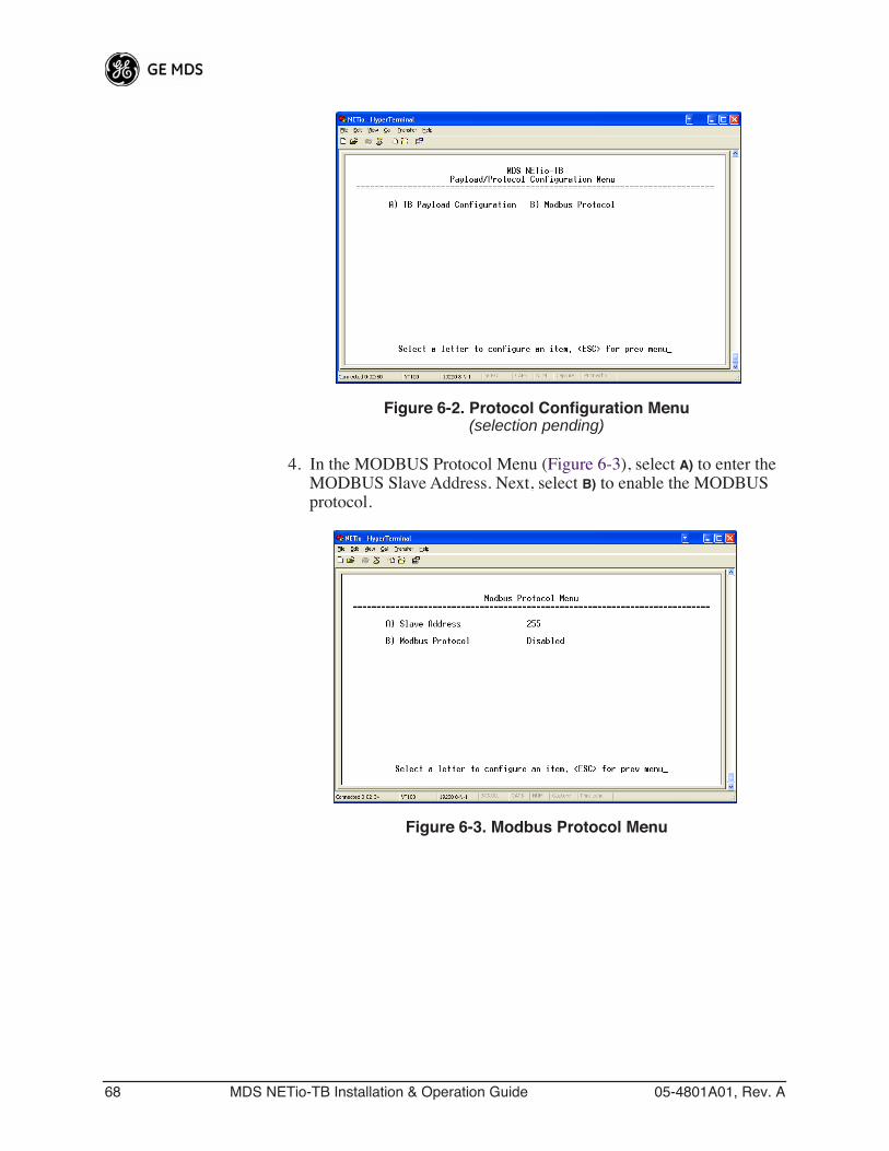
68 MDS NETio-TB Installation & Operation Guide 05-4801A01, Rev. A
Invisible place holder
Figure 6-2. Protocol Configuration Menu(selection pending)
4. In the MODBUS Protocol Menu (Figure 6-3), select A) to enter the MODBUS Slave Address. Next, select B) to enable the MODBUS protocol.
Invisible place holder
Figure 6-3. Modbus Protocol Menu
05-4801A01, Rev. A MDS NETio-TB Installation & Operation Guide 69
7 MAINTENANCE & SUPPORT FUNCTIONS
7 Chapter Counter Reset Paragraph7.1 INTRODUCTION ....................................................................... 94
7.2 NETio TransNET RADIO MAINTENANCE & SUPPORT........... 94
7.2.1 Modifying NETio TransNET RF Output Power ............................947.2.2 Performance, Statistics, RSSI Information ..................................957.2.3 Setting Encryption Approved Access Points and Passwords ......967.2.4 Maintenance/Tools/Date and Time ..............................................97
7.3 WeXP & NETio MODULE MAINTENANCE............................... 97
7.3.1 View/Set Expansion Module WeXP RF Power ............................987.3.2 Changing Base Module WeXP RF Output Power .......................987.3.3 Changing WeXP RF Channel ......................................................997.3.4 WeXP RSSI and Backplane Communication Statistics ...............99
7.4 DEVICE, MODULE and I/O POINT DESCRIPTIONS ............. 101
7.4.1 Changing the NETio Device Name ...........................................1017.4.2 Changing NETio Module and I/O Point Names .........................102
7.5 TECHNICAL SPECIFICATIONS.............................................. 102
General ...........................................................................................102NETio Base module........................................................................102NETio Expansion module models ..................................................103Analog Input ...................................................................................103Digital Inputs...................................................................................103Analog Outputs...............................................................................103Digital Outputs ................................................................................103900 MHz Model Radio specifications .............................................1042.4 GHz Model Radio specifications...............................................104WeXP radio specifications - 802.15.4.............................................104Mechanical .....................................................................................104Agency Approvals...........................................................................104
7.6 dBm-WATTS-VOLTS CONVERSION CHART ......................... 106
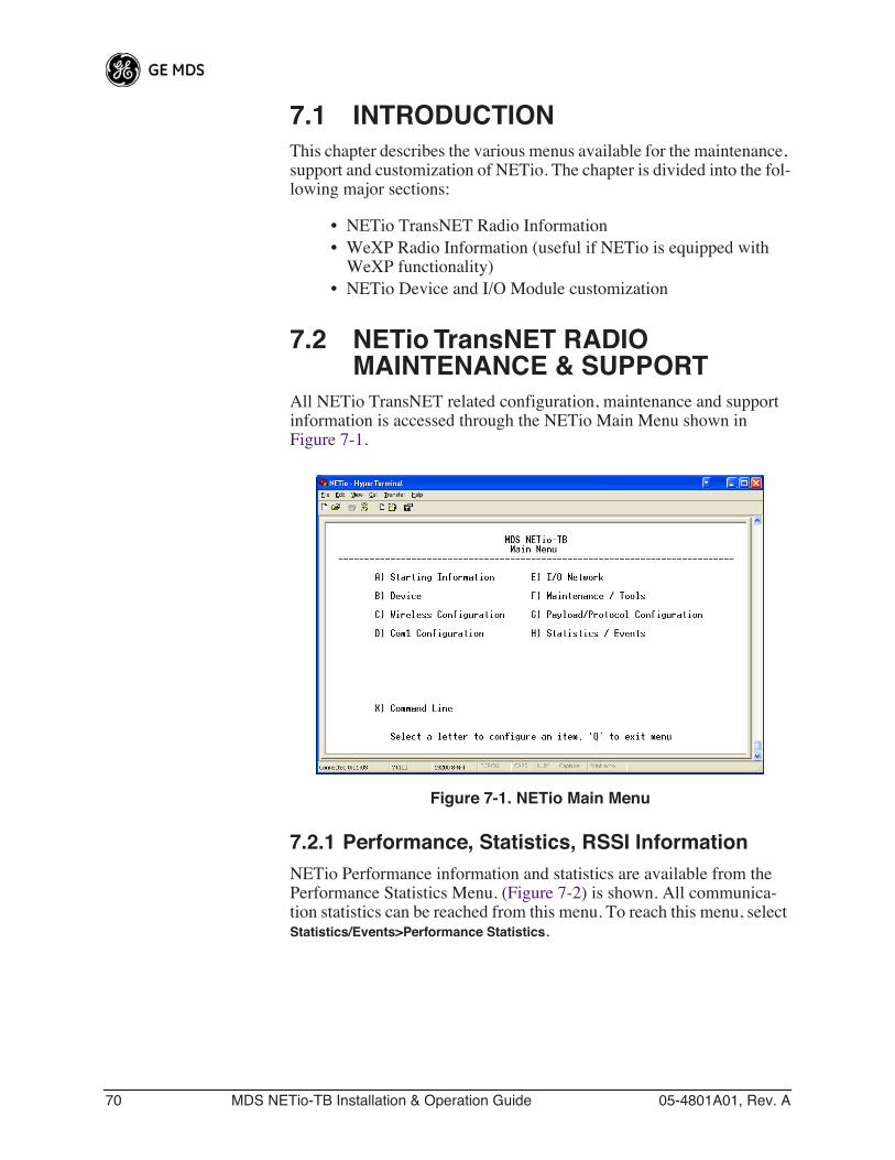
70 MDS NETio-TB Installation & Operation Guide 05-4801A01, Rev. A
7.1 INTRODUCTIONThis chapter describes the various menus available for the maintenance, support and customization of NETio. The chapter is divided into the fol-lowing major sections:
• NETio TransNET Radio Information• WeXP Radio Information (useful if NETio is equipped with
WeXP functionality)• NETio Device and I/O Module customization
7.2 NETio TransNET RADIO MAINTENANCE & SUPPORT
All NETio TransNET related configuration, maintenance and support information is accessed through the NETio Main Menu shown in Figure 7-1.
Invisible place holder
Figure 7-1. NETio Main Menu
7.2.1 Performance, Statistics, RSSI InformationNETio Performance information and statistics are available from the Performance Statistics Menu. (Figure 7-2) is shown. All communica-tion statistics can be reached from this menu. To reach this menu, select Statistics/Events>Performance Statistics.
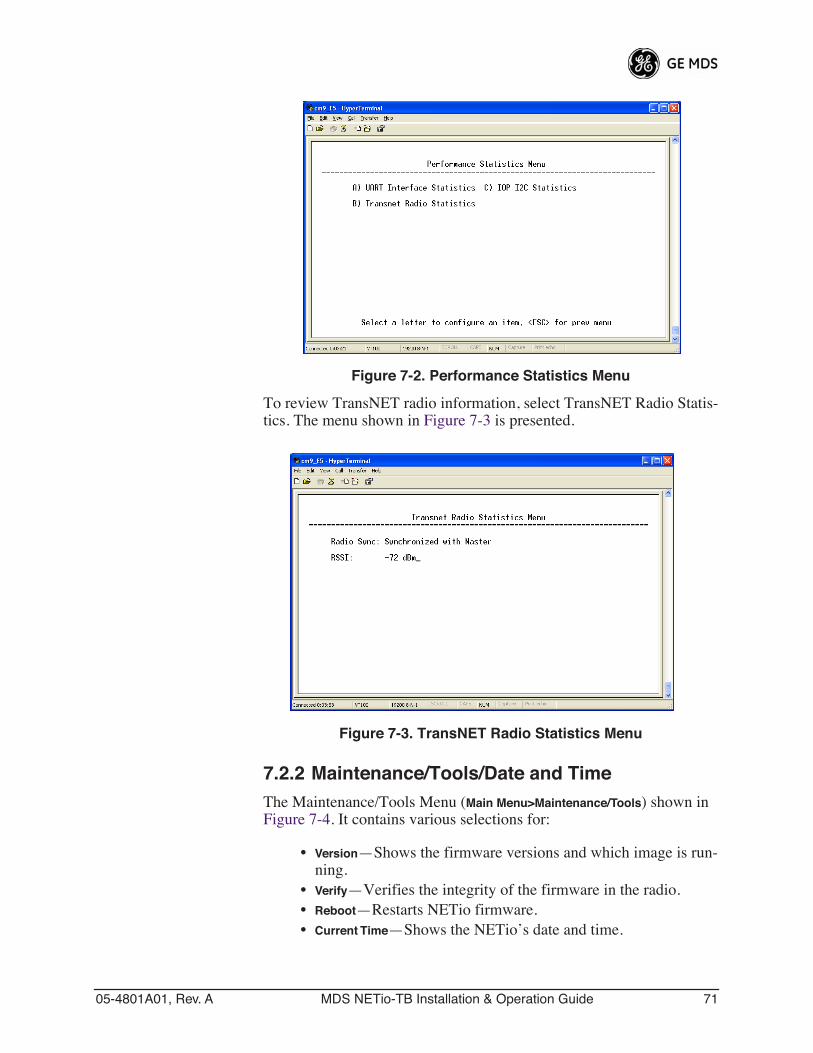
05-4801A01, Rev. A MDS NETio-TB Installation & Operation Guide 71
Invisible place holder
Figure 7-2. Performance Statistics Menu
To review TransNET radio information, select TransNET Radio Statis-tics. The menu shown in Figure 7-3 is presented.
Invisible place holder
Figure 7-3. TransNET Radio Statistics Menu
7.2.2 Maintenance/Tools/Date and TimeThe Maintenance/Tools Menu (Main Menu>Maintenance/Tools) shown in Figure 7-4. It contains various selections for:
• Version—Shows the firmware versions and which image is run-ning.
• Verify—Verifies the integrity of the firmware in the radio.• Reboot—Restarts NETio firmware.• Current Time—Shows the NETio’s date and time.
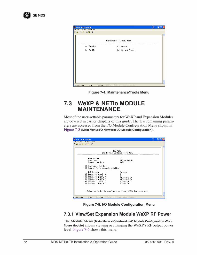
72 MDS NETio-TB Installation & Operation Guide 05-4801A01, Rev. A
Invisible place holder
Figure 7-4. Maintenance/Tools Menu
7.3 WeXP & NETio MODULE MAINTENANCE
Most of the user-settable parameters for WeXP and Expansion Modules are covered in earlier chapters of this guide. The few remaining param-eters are accessed from the I/O Module Configuration Menu shown in Figure 7-5 (Main Menu>I/O Network>I/O Module Configuration).
Invisible place holder
Figure 7-5. I/O Module Configuration Menu
7.3.1 View/Set Expansion Module WeXP RF PowerThe Module Menu (Main Menu>I/O Network>I/O Module Configuration>Con-figure Module) allows viewing or changing the WeXP’s RF output power level. Figure 7-6 shows this menu.
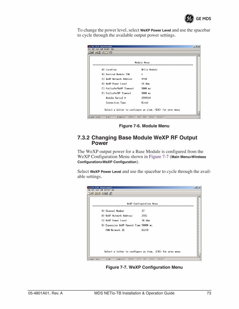
05-4801A01, Rev. A MDS NETio-TB Installation & Operation Guide 73
To change the power level, select WeXP Power Level and use the spacebar to cycle through the available output power settings.
Invisible place holder
Figure 7-6. Module Menu
7.3.2 Changing Base Module WeXP RF Output Power
The WeXP output power for a Base Module is configured from the WeXP Configuration Menu shown in Figure 7-7 (Main Menu>Wireless Configuration>WeXP Configuration).
Select WeXP Power Level and use the spacebar to cycle through the avail-able settings.
Invisible place holder
Figure 7-7. WeXP Configuration Menu
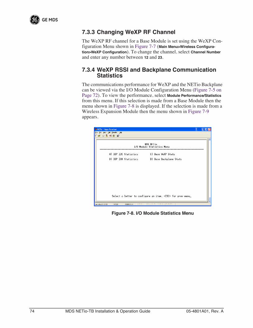
74 MDS NETio-TB Installation & Operation Guide 05-4801A01, Rev. A
7.3.3 Changing WeXP RF ChannelThe WeXP RF channel for a Base Module is set using the WeXP Con-figuration Menu shown in Figure 7-7 (Main Menu>Wireless Configura-tion>WeXP Configuration). To change the channel, select Channel Number and enter any number between 12 and 23.
7.3.4 WeXP RSSI and Backplane Communication Statistics
The communications performance for WeXP and the NETio Backplane can be viewed via the I/O Module Configuration Menu (Figure 7-5 on Page 72). To view the performance, select Module Performance/Statistics from this menu. If this selection is made from a Base Module then the menu shown in Figure 7-8 is displayed. If the selection is made from a Wireless Expansion Module then the menu shown in Figure 7-9 appears.
Invisible place holder
Figure 7-8. I/O Module Statistics Menu
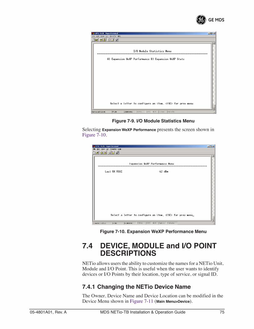
05-4801A01, Rev. A MDS NETio-TB Installation & Operation Guide 75
Invisible place holder
Figure 7-9. I/O Module Statistics Menu
Selecting Expansion WeXP Performance presents the screen shown in Figure 7-10.
Invisible place holder
Figure 7-10. Expansion WeXP Performance Menu
7.4 DEVICE, MODULE and I/O POINT DESCRIPTIONS
NETio allows users the ability to customize the names for a NETio Unit, Module and I/O Point. This is useful when the user wants to identify devices or I/O Points by their location, type of service, or signal ID.
7.4.1 Changing the NETio Device NameThe Owner, Device Name and Device Location can be modified in the Device Menu shown in Figure 7-11 (Main Menu>Device).
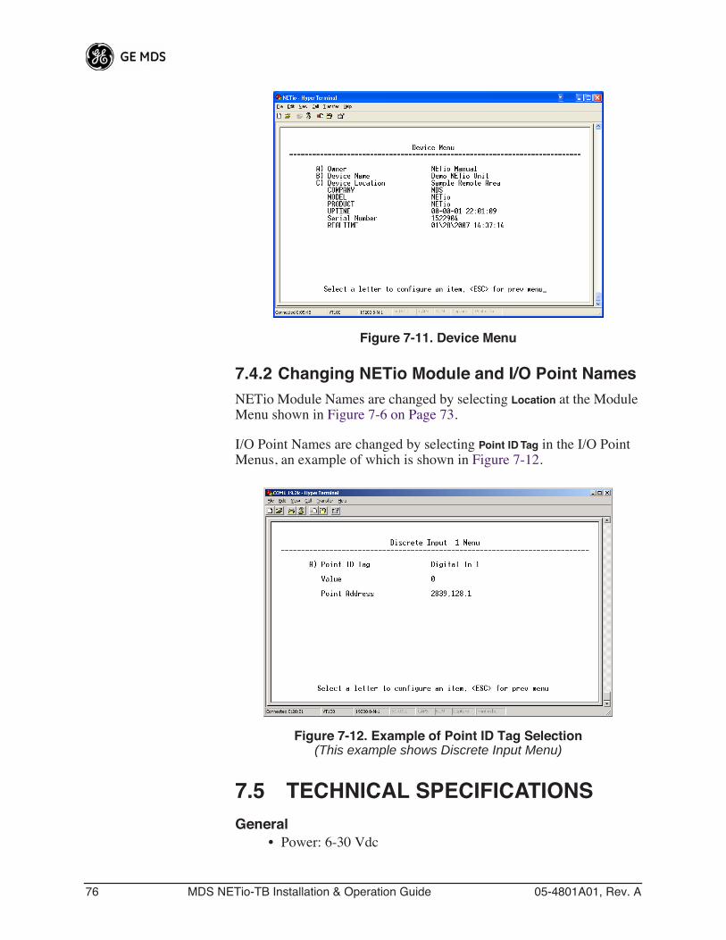
76 MDS NETio-TB Installation & Operation Guide 05-4801A01, Rev. A
Invisible place holder
Figure 7-11. Device Menu
7.4.2 Changing NETio Module and I/O Point NamesNETio Module Names are changed by selecting Location at the Module Menu shown in Figure 7-6 on Page 73.
I/O Point Names are changed by selecting Point ID Tag in the I/O Point Menus, an example of which is shown in Figure 7-12.
Invisible place holder
Figure 7-12. Example of Point ID Tag Selection(This example shows Discrete Input Menu)
7.5 TECHNICAL SPECIFICATIONSGeneral
• Power: 6-30 Vdc
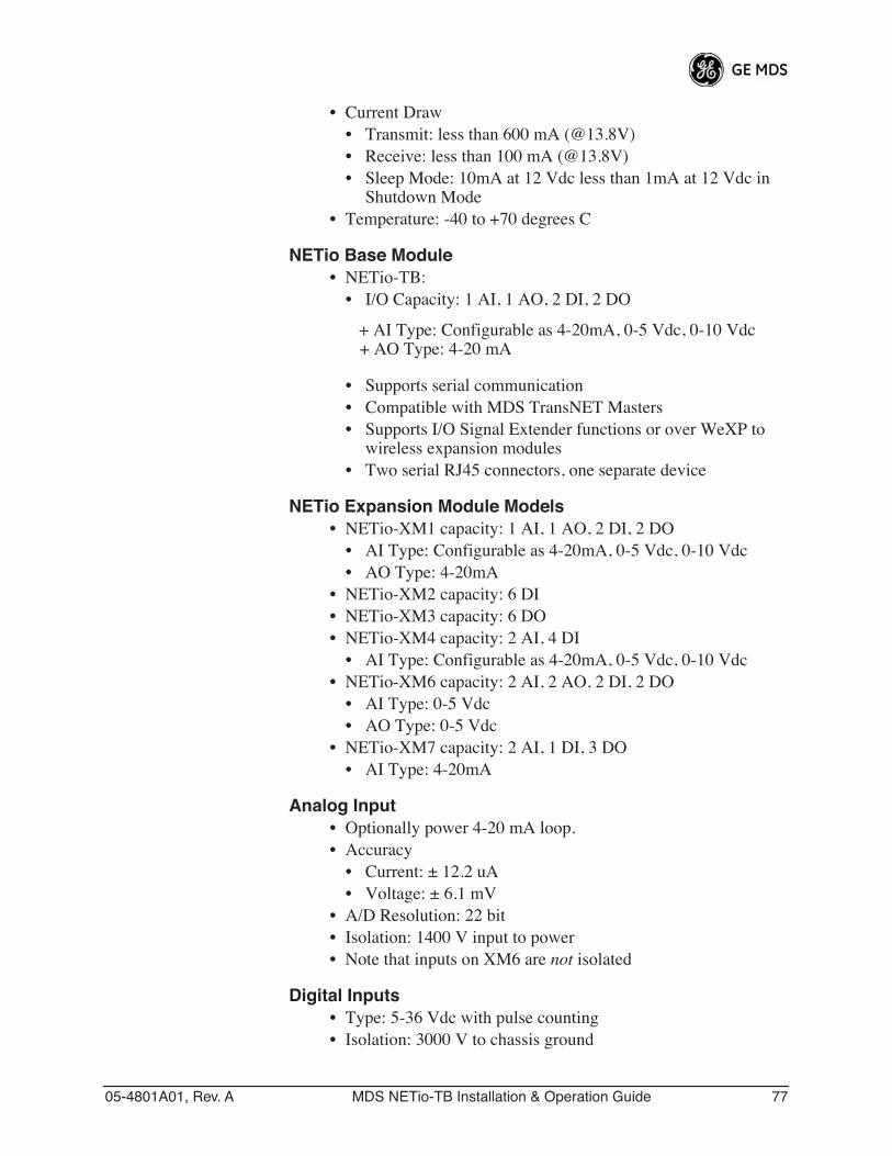
05-4801A01, Rev. A MDS NETio-TB Installation & Operation Guide 77
• Current Draw• Transmit: less than 600 mA (@13.8V)• Receive: less than 100 mA (@13.8V)• Sleep Mode: 10mA at 12 Vdc less than 1mA at 12 Vdc in
Shutdown Mode• Temperature: -40 to +70 degrees C
NETio Base Module• NETio-TB:
• I/O Capacity: 1 AI, 1 AO, 2 DI, 2 DO
+ AI Type: Configurable as 4-20mA, 0-5 Vdc, 0-10 Vdc+ AO Type: 4-20 mA
• Supports serial communication• Compatible with MDS TransNET Masters• Supports I/O Signal Extender functions or over WeXP to
wireless expansion modules• Two serial RJ45 connectors, one separate device
NETio Expansion Module Models• NETio-XM1 capacity: 1 AI, 1 AO, 2 DI, 2 DO
• AI Type: Configurable as 4-20mA, 0-5 Vdc, 0-10 Vdc• AO Type: 4-20mA
• NETio-XM2 capacity: 6 DI• NETio-XM3 capacity: 6 DO• NETio-XM4 capacity: 2 AI, 4 DI
• AI Type: Configurable as 4-20mA, 0-5 Vdc, 0-10 Vdc• NETio-XM6 capacity: 2 AI, 2 AO, 2 DI, 2 DO
• AI Type: 0-5 Vdc• AO Type: 0-5 Vdc
• NETio-XM7 capacity: 2 AI, 1 DI, 3 DO• AI Type: 4-20mA
Analog Input• Optionally power 4-20 mA loop.• Accuracy
• Current: ± 12.2 uA• Voltage: ± 6.1 mV
• A/D Resolution: 22 bit• Isolation: 1400 V input to power• Note that inputs on XM6 are not isolated
Digital Inputs• Type: 5-36 Vdc with pulse counting• Isolation: 3000 V to chassis ground
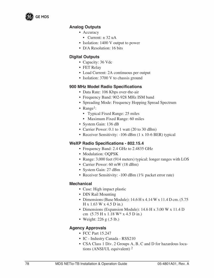
78 MDS NETio-TB Installation & Operation Guide 05-4801A01, Rev. A
Analog Outputs• Accuracy
• Current: ± 32 uA• Isolation: 1400 V output to power• D/A Resolution: 16 bits
Digital Outputs• Capacity: 36 Vdc• FET Relay• Load Current: 2A continuous per output• Isolation: 3700 V to chassis ground
900 MHz Model Radio Specifications• Data Rate: 106 Kbps over-the-air• Frequency Band: 902-928 MHz ISM band• Spreading Mode: Frequency Hopping Spread Spectrum• Range1:
• Typical Fixed Range: 25 miles• Maximum Fixed Range: 60 miles
• System Gain: 136 dB• Carrier Power: 0.1 to 1 watt (20 to 30 dBm)• Receiver Sensitivity: -106 dBm (1 x 10⁻⁶ BER) typical
WeXP Radio Specifications - 802.15.4• Frequency Band: 2.4 GHz to 2.4835 GHz• Modulation: OQPSK• Range: 3,000 feet (914 meters) typical; longer ranges with LOS• Carrier Power: 60 mW (18 dBm)• System Gain: 27 dBm• Receiver Sensitivity: -100 dBm (1% packet error rate)
Mechanical• Case: High impact plastic• DIN Rail Mounting• Dimensions (Base Module): 14.6 H x 4.14 W x 11.4 D cm. (5.75
H x 1.63 W x 4.5 D in.)• Dimensions (Expansion Module): 14.6 H x 3.00 W x 11.4 D
cm (5.75 H x 1.18 W* x 4.5 D in.)• Weight: 226 g (.5 lb.)
Agency Approvals• FCC Part 15.247• IC - Industry Canada - RSS210• CSA Class 1 Div. 2 Groups A, B, C and D for hazardous loca-
tions (ANSI/UL equivalent) 2
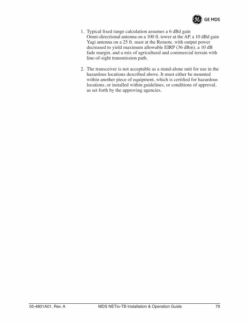
05-4801A01, Rev. A MDS NETio-TB Installation & Operation Guide 79
1. Typical fixed range calculation assumes a 6 dBd gain Omni-directional antenna on a 100 ft. tower at the AP, a 10 dBd gain Yagi antenna on a 25 ft. mast at the Remote, with output power decreased to yield maximum allowable EIRP (36 dBm), a 10 dB fade margin, and a mix of agricultural and commercial terrain with line-of-sight transmission path.
2. The transceiver is not acceptable as a stand-alone unit for use in the hazardous locations described above. It must either be mounted within another piece of equipment, which is certified for hazardous locations, or installed within guidelines, or conditions of approval, as set forth by the approving agencies.
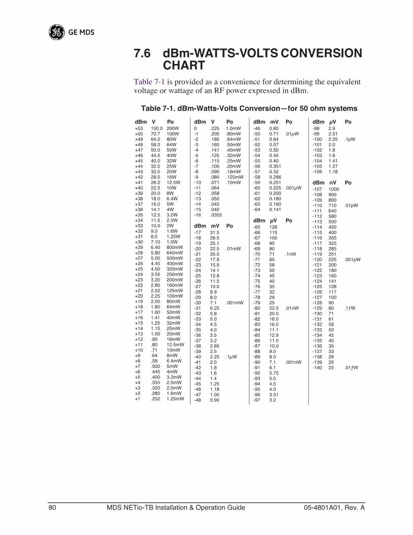
80 MDS NETio-TB Installation & Operation Guide 05-4801A01, Rev. A
7.6 dBm-WATTS-VOLTS CONVERSION CHART
Table 7-1 is provided as a convenience for determining the equivalent voltage or wattage of an RF power expressed in dBm.
Table 7-1. dBm-Watts-Volts Conversion—for 50 ohm systems
dBm V Po+53 100.0 200W+50 70.7 100W+49 64.0 80W+48 58.0 64W+47 50.0 50W+46 44.5 40W+45 40.0 32W+44 32.5 25W+43 32.0 20W+42 28.0 16W+41 26.2 12.5W+40 22.5 10W+39 20.0 8W+38 18.0 6.4W+37 16.0 5W+36 14.1 4W+35 12.5 3.2W+34 11.5 2.5W+33 10.0 2W+32 9.0 1.6W+31 8.0 1.25W+30 7.10 1.0W+29 6.40 800mW+28 5.80 640mW+27 5.00 500mW+26 4.45 400mW+25 4.00 320mW+24 3.55 250mW+23 3.20 200mW+22 2.80 160mW+21 2.52 125mW+20 2.25 100mW+19 2.00 80mW+18 1.80 64mW+17 1.60 50mW+16 1.41 40mW+15 1.25 32mW+14 1.15 25mW+13 1.00 20mW+12 .90 16mW+11 .80 12.5mW+10 .71 10mW+9 .64 8mW+8 .58 6.4mW+7 .500 5mW+6 .445 4mW+5 .400 3.2mW+4 .355 2.5mW+3 .320 2.0mW+2 .280 1.6mW+1 .252 1.25mW
dBm V Po0 .225 1.0mW-1 .200 .80mW-2 .180 .64mW-3 .160 .50mW-4 .141 .40mW-5 .125 .32mW-6 .115 .25mW-7 .100 .20mW-8 .090 .16mW-9 .080 .125mW-10 .071 .10mW-11 .064-12 .058-13 .050-14 .045-15 .040-16 .0355
dBm mV Po-17 31.5-18 28.5-19 25.1-20 22.5 .01mW-21 20.0-22 17.9-23 15.9-24 14.1-25 12.8-26 11.5-27 10.0-28 8.9-29 8.0-30 7.1 .001mW-31 6.25-32 5.8-33 5.0-34 4.5-35 4.0-36 3.5-37 3.2-38 2.85-39 2.5-40 2.25 .1μW-41 2.0-42 1.8-43 1.6-44 1.4-45 1.25-46 1.18-47 1.00-48 0.90
dBm mV Po-49 0.80-50 0.71 .01μW-51 0.64-52 0.57-53 0.50-54 0.45-55 0.40-56 0.351-57 0.32-58 0.286-59 0.251-60 0.225 .001μW-61 0.200-62 0.180-63 0.160-64 0.141
dBm μV Po-65 128-66 115-67 100-68 90-69 80-70 71 .1nW-71 65-72 58-73 50-74 45-75 40-76 35-77 32-78 29-79 25-80 22.5 .01nW-81 20.0-82 18.0-83 16.0-84 11.1-85 12.9-86 11.5-87 10.0-88 9.0-89 8.0-90 7.1 .001nW-91 6.1-92 5.75-93 5.0-94 4.5-95 4.0-96 3.51-97 3.2
dBm μV Po-98 2.9-99 2.51-100 2.25 .1pW-101 2.0-102 1.8-103 1.6-104 1.41-105 1.27-106 1.18
dBm nV Po-107 1000-108 900-109 800-110 710 .01pW-111 640-112 580-113 500-114 450-115 400-116 355-117 325-118 285-119 251-120 225 .001pW-121 200-122 180-123 160-124 141-125 128-126 117-127 100-128 90-129 80 .1ƒW-130 71-131 61-132 58-133 50-134 45-135 40-136 35-137 33-138 29-139 25-140 23 .01ƒW
IN CASE OF DIFFICULTY...
GE MDS products are designed for long life and trouble-free operation. However, this equipment, as with all electronic equipment, may have an occasional component failure. The following information will assist you in the event that servicing becomes necessary.
TECHNICAL ASSISTANCE
Technical assistance for GE MDS products is available from our Technical Support Department during business hours (8:00 A.M.—5:30 P.M. Eastern Time). When calling, please give the complete model number of the radio, along with a description of the trouble/symptom(s) that you are experiencing. In many cases, problems can be resolved over the telephone, without the need for returning the unit to the factory. Please use one of the following means for product assistance:
Phone: 585 241-5510 E-Mail: [email protected]
FAX: 585 242-8369 Web: www.GEmds.com
FACTORY SERVICE
Component level repair of this equipment is not recommended in the field. Many components are installed using surface mount technology, which requires specialized training and equipment for proper servicing. For this reason, the equipment should be returned to the factory for any PC board repairs. The factory is best equipped to diagnose, repair and align your radio to its proper operating specifications.
If return of the equipment is necessary, you must obtain a Service Request Order (SRO) number. This number helps expedite the repair so that the equipment can be repaired and returned to you as quickly as possible. Please be sure to include the SRO number on the outside of the shipping box, and on any corre-spondence relating to the repair. No equipment will be accepted for repair without an SRO number.
SRO numbers are issued online at www.GEmds.com/support/product/sro/. Your number will be issued immediately after the required information is entered. Please be sure to have the model number(s), serial number(s), detailed reason for return, "ship to" address, "bill to" address, and contact name, phone number, and fax number available when requesting an SRO number. A purchase order number or pre-payment will be required for any units that are out of warranty, or for product conversion.
If you prefer, you may contact our Product Services department to obtain an SRO number:
Phone Number: 585-241-5540Fax Number: 585-242-8400E-mail Address: [email protected]
The radio must be properly packed for return to the factory. The original shipping container and packaging materials should be used whenever possible. All factory returns should be addressed to:
GE MDS, LLCProduct Services Department(SRO No. XXXX)175 Science ParkwayRochester, NY 14620 USA
When repairs have been completed, the equipment will be returned to you by the same shipping method used to send it to the factory. Please specify if you wish to make different shipping arrangements. To inquire about an in-process repair, you may contact our Product Services Group using the telephone, Fax, or E-mail information given above.

GE MDS, LLC
Rochester, NY 14620General Business: +1 585 242-9600
FAX: +1 585 242-9620Web: www.GEmds.com
175 Science Parkway