Embed Size (px)
Citation preview
DC Power Grids for Buildings
U. Boeke Philips Research
Philips Electronics Netherland B.V Eindhoven, the Netherlands [email protected]
M. Wendt Philips Research
Philips Electronics Netherland B.V Eindhoven, the Netherlands
Abstract— Direct current (DC) power grids are an interesting
option for buildings to connect natural DC power sources such as photovoltaic power systems with DC loads like lighting, IT systems as well as speed-controlled electric motors of heating, ventilation and air-conditioning systems. The paper documents learnings, measurements and efficiency differences of a test bed installation with both a 230 V AC and a 380 V DC grid. Both sub-systems supply LED luminaires with electricity from utility mains and AC respectively DC grid connected photovoltaic solar power systems. An efficiency advantage of 2 % has been measured with the 2 kW DC grid test bed. 5 % energy savings are described as potential.
Keywords—Efficiency; AC mains; DC grid; central rectifier; photovoltaics; solar power; LED lighting; DCC+G
I. INTRODUCTION
Buildings shall become more energy efficient and avoid CO2 emissions that prohibits to use gas or oil for e.g. building heating. Instead buildings shall collect needed energy from buildings environment to realize a net-zero energy balance in the course of a year [1]. These requirements will most likely result in all-electric buildings equipped with photovoltaic solar power systems on buildings roofs and heat-pumps for building heating or cooling [2, 3]. Battery energy storage units can make solar energy available at night and a utility grid access allows an exchange of electric energy with other buildings and power sources such as wind parks outside of cities. When analyzing the listed electric applications of buildings readers may notice that these are all DC operating units by nature such as solar cells, batteries, LED lighting or by the application of electronic controls that converts AC motors in a DC operated speed controlled drive system. Thus modern buildings benefit from DC power grids to realize a power exchange between DC sources, storage and loads. To learn about such systems the partners of the open innovation project “Direct Current Components +Grid” (DCC+G), including Philips Research, have realized test bed installations with 380 V DC grids and hybrid supply from solar power systems and central AC mains rectifiers [4, 5]. DC grids of the DCC+G partners are characterized by a relative small service voltage range of 360 V …400 V DC such that DC loads can be designed for a narrow supply voltage range. Thus batteries of energy storage modules are preferably connected to such a DC grid via DC/DC converters. In opposite to that the standard of the European Telecommunications Standards Institute (ETSI) considers a direct grid connection of battery strings that results in a larger DC service voltage range from 260 V to 400 V depending on the battery charge level [6].
II. EINDHOVEN OFFICE TEST BED An office lighting test bed installation with both
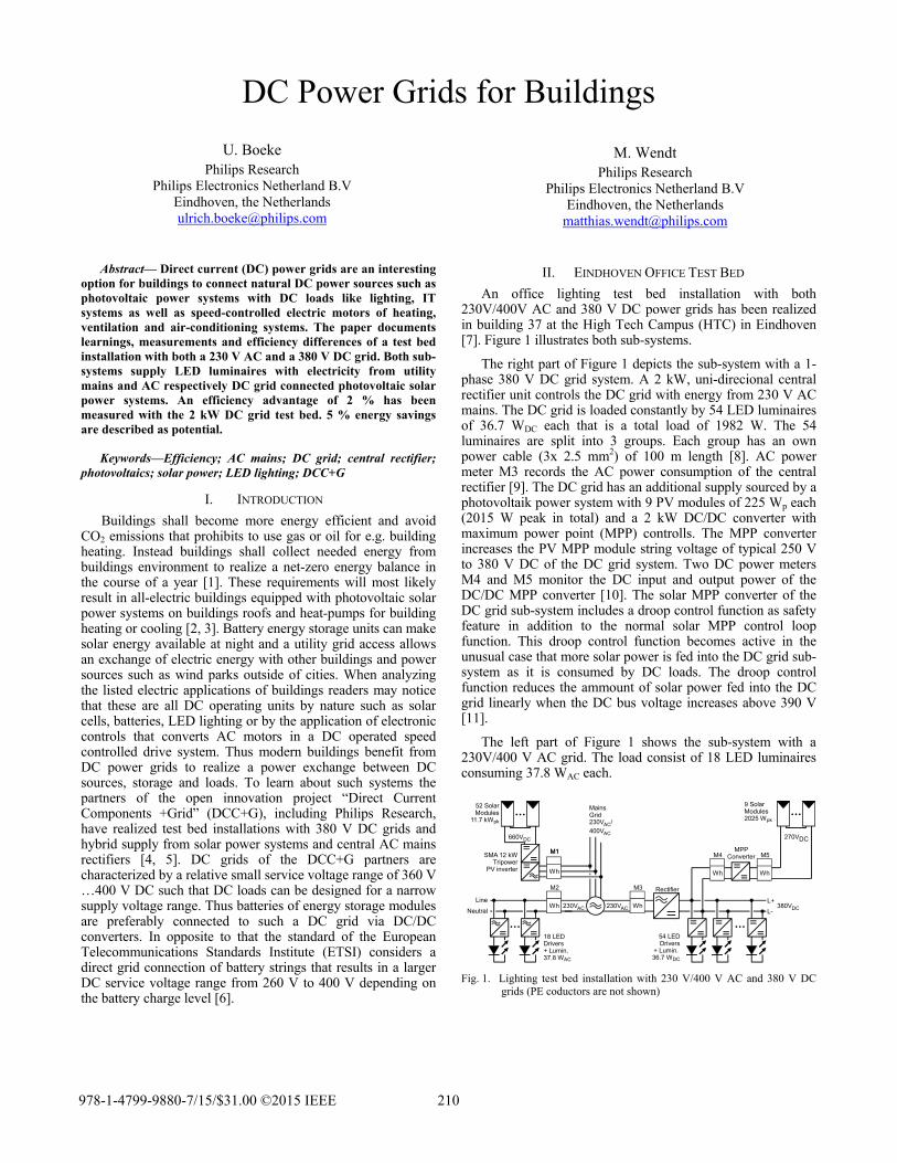
230V/400V AC and 380 V DC power grids has been realized in building 37 at the High Tech Campus (HTC) in Eindhoven [7]. Figure 1 illustrates both sub-systems.
The right part of Figure 1 depicts the sub-system with a 1-phase 380 V DC grid system. A 2 kW, uni-direcional central rectifier unit controls the DC grid with energy from 230 V AC mains. The DC grid is loaded constantly by 54 LED luminaires of 36.7 WDC each that is a total load of 1982 W. The 54 luminaires are split into 3 groups. Each group has an own power cable (3x 2.5 mm2) of 100 m length [8]. AC power meter M3 records the AC power consumption of the central rectifier [9]. The DC grid has an additional supply sourced by a photovoltaik power system with 9 PV modules of 225 Wp each (2015 W peak in total) and a 2 kW DC/DC converter with maximum power point (MPP) controlls. The MPP converter increases the PV MPP module string voltage of typical 250 V to 380 V DC of the DC grid system. Two DC power meters M4 and M5 monitor the DC input and output power of the DC/DC MPP converter [10]. The solar MPP converter of the DC grid sub-system includes a droop control function as safety feature in addition to the normal solar MPP control loop function. This droop control function becomes active in the unusual case that more solar power is fed into the DC grid sub-system as it is consumed by DC loads. The droop control function reduces the ammount of solar power fed into the DC grid linearly when the DC bus voltage increases above 390 V [11].
The left part of Figure 1 shows the sub-system with a 230V/400 V AC grid. The load consist of 18 LED luminaires consuming 37.8 WAC each.
Fig. 1. Lighting test bed installation with 230 V/400 V AC and 380 V DC
grids (PE coductors are not shown)
MPPConverter
9 SolarModules2025 Wpk
54 LEDDrivers
+ Lumin. 36.7 WDC
MainsGrid230VAC/400VAC
Rectifier
52 SolarModules
11.7 kWpk
SMA 12 kWTripower
PV inverter
230VAC 380VDC
18 LEDDrivers+ Lumin. 37.8 WAC
270VDC660VDC
WhWh
Wh
230VAC
Wh Wh
M1M1
M2 M3
M4 M5
L+
L-
Line
Neutral
978-1-4799-9880-7/15/$31.00 ©2015 IEEE 210
The the addicorreinpugrouthe sbothmetethe nsysteconnkW powand the Athe dratio
AinstaAC and In thcanncan dAC iFor brea
Fig. 2
LED luminaiDC grid sytionally an ection circuit
ut power per up to power msame type as u
h sub-systems er M2 are mulnumber of luem also makenected to the 3
SMA Sunnywer feed into A
energy meter AC solar powedata of energyo of the used P
All LED lumialled in the sarelay switcheswitches-off i
hat way all sonot be feed intdo. The lightininput of the cegeneral systemkers are instal
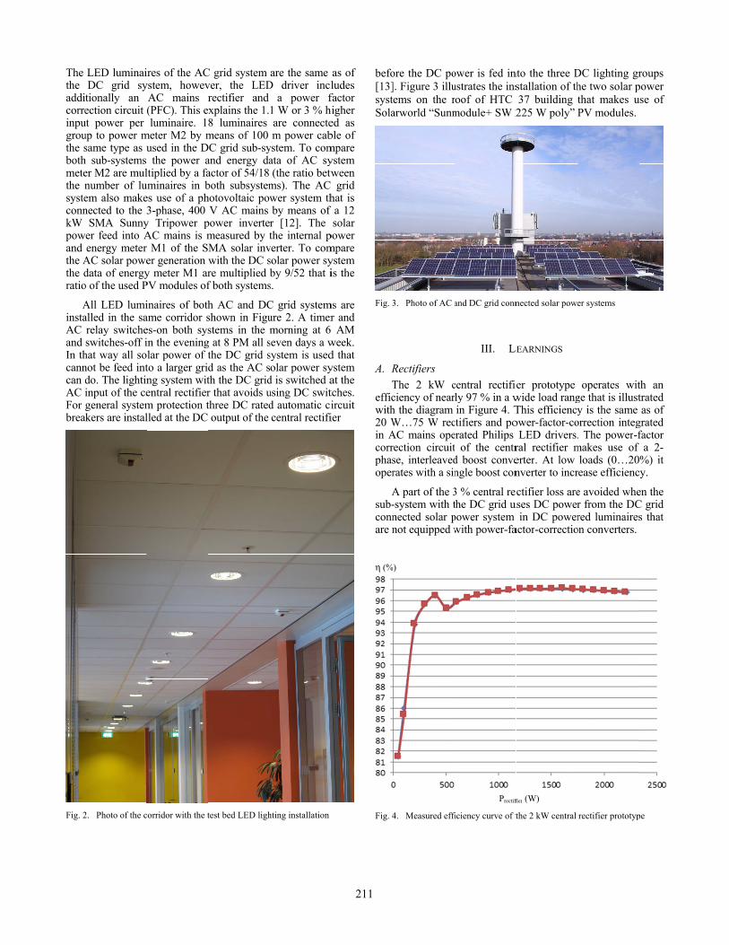
2. Photo of the c
ires of the ACystem, howev
AC mains r(PFC). This eluminaire. 1
meter M2 by mused in the Dthe power a
ltiplied by a fauminaires in bes use of a ph3-phase, 400
y Tripower pAC mains is mr M1 of the Ser generation wy meter M1 arPV modules of
inaires of bothame corridor ses-on both sysin the eveninglar power of tto a larger gridng system witentral rectifierm protection tlled at the DC
corridor with the t
C grid system ver, the LEDrectifier and xplains the 1.8 luminaires means of 100
DC grid sub-syand energy daactor of 54/18 both subsystemhotovoltaic pow
V AC mains power invertemeasured by tMA solar invwith the DC sre multiplied f both systems
h AC and DCshown in Figustems in the m
g at 8 PM all sthe DC grid sd as the AC sth the DC gridr that avoids uthree DC ratedoutput of the
test bed LED ligh
are the same D driver incl
a power f1 W or 3 % hiare connectem power cab
ystem. To comata of AC sy(the ratio betw
ms). The AC wer system thby means of r [12]. The the internal p
verter. To comsolar power syby 9/52 that i
s.
C grid systemure 2. A timermorning at 6
seven days a wsystem is usedolar power sy
d is switched ausing DC switd automatic cicentral rectifi
hting installation
as of ludes factor igher
ed as ble of mpare ystem ween grid
hat is a 12 solar
power mpare ystem is the
ms are r and AM
week. d that ystem at the tches. ircuit ier
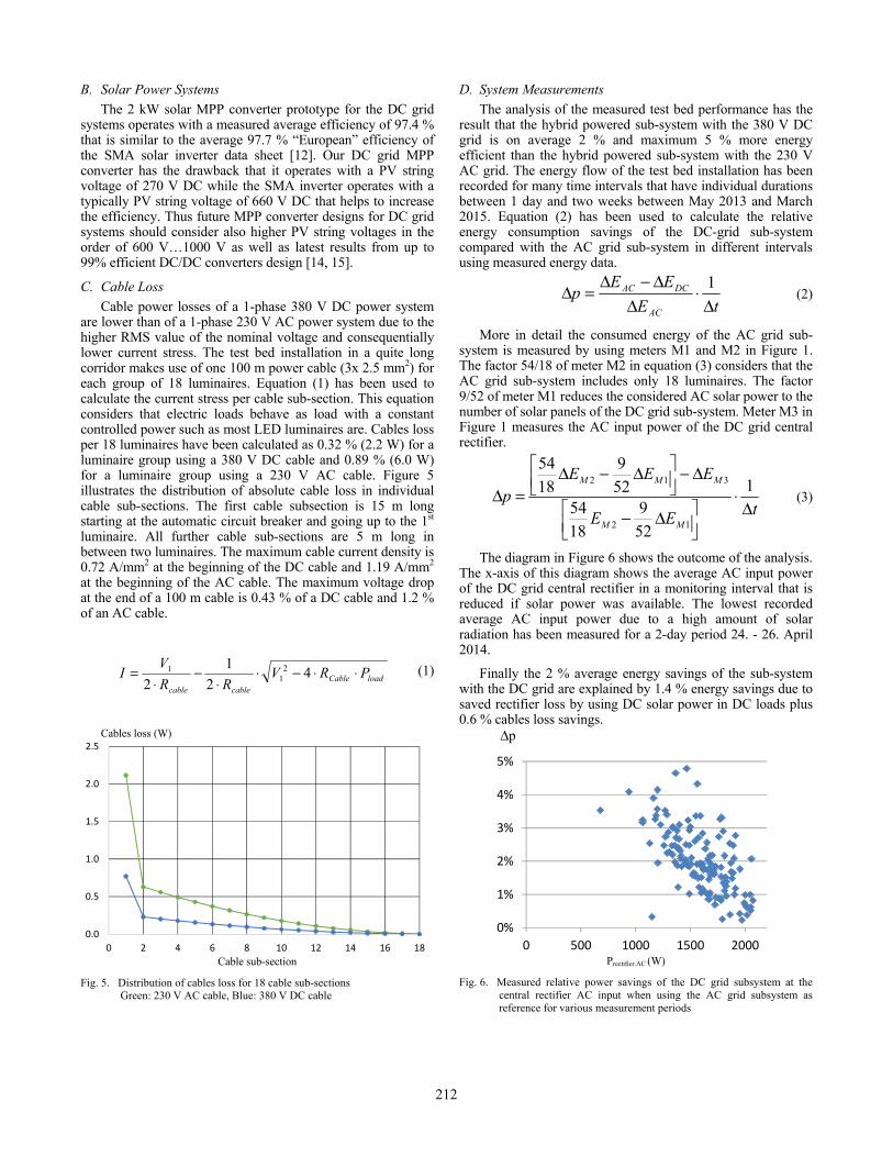
befo[13]systSola
Fig. 3
A. RT
efficwith20 Win Acorrphasoper
Asub-connare n
η (%
Fig. 4
ore the DC po]. Figure 3 illuems on the rarworld “Sunm
3. Photo of AC a
Rectifiers The 2 kW cciency of nearh the diagram W…75 W recAC mains operection circuitse, interleavedrates with a sin
A part of the 3-system with tnected solar pnot equipped w
)
4. Measured effi
ower is fed intustrates the insroof of HTC module+ SW 2
and DC grid conn
III. LE
central rectifiely 97 % in a win Figure 4. T
ctifiers and poerated Philips t of the centrd boost convengle boost con
3 % central recthe DC grid uspower system with power-fa
Prectifi
iciency curve of t
nto the three Dstallation of th37 building 225 W poly”
nected solar powe
LEARNINGS
er prototype wide load rangThis efficiencyower-factor-co
LED drivers.ral rectifier merter. At low nverter to incr
ctifier loss areuses DC power
in DC poweractor-correctio
fier (W)
the 2 kW central
DC lighting grhe two solar pthat makes uPV modules.
er systems
operates witge that is illusty is the same
orrection integ. The power-f
makes use of loads (0…20
rease efficienc
e avoided wher from the DCred luminaires
on converters.
rectifier prototyp
roups power use of
th an trated as of
grated factor
a 2-0%) it cy.
en the C grid s that
pe
211
B. Solar Power Systems The 2 kW solar MPP converter prototype for the DC grid
systems operates with a measured average efficiency of 97.4 % that is similar to the average 97.7 % “European” efficiency of the SMA solar inverter data sheet [12]. Our DC grid MPP converter has the drawback that it operates with a PV string voltage of 270 V DC while the SMA inverter operates with a typically PV string voltage of 660 V DC that helps to increase the efficiency. Thus future MPP converter designs for DC grid systems should consider also higher PV string voltages in the order of 600 V…1000 V as well as latest results from up to 99% efficient DC/DC converters design [14, 15].
C. Cable Loss Cable power losses of a 1-phase 380 V DC power system
are lower than of a 1-phase 230 V AC power system due to the higher RMS value of the nominal voltage and consequentially lower current stress. The test bed installation in a quite long corridor makes use of one 100 m power cable (3x 2.5 mm2) for each group of 18 luminaires. Equation (1) has been used to calculate the current stress per cable sub-section. This equation considers that electric loads behave as load with a constant controlled power such as most LED luminaires are. Cables loss per 18 luminaires have been calculated as 0.32 % (2.2 W) for a luminaire group using a 380 V DC cable and 0.89 % (6.0 W) for a luminaire group using a 230 V AC cable. Figure 5 illustrates the distribution of absolute cable loss in individual cable sub-sections. The first cable subsection is 15 m long starting at the automatic circuit breaker and going up to the 1st luminaire. All further cable sub-sections are 5 m long in between two luminaires. The maximum cable current density is 0.72 A/mm2 at the beginning of the DC cable and 1.19 A/mm2 at the beginning of the AC cable. The maximum voltage drop at the end of a 100 m cable is 0.43 % of a DC cable and 1.2 % of an AC cable.
loadCablecablecable
PRVRR
VI ⋅⋅−⋅⋅
−⋅
= 42
1
22
11 (1)
Cables loss (W)
Cable sub-section
Fig. 5. Distribution of cables loss for 18 cable sub-sections Green: 230 V AC cable, Blue: 380 V DC cable
D. System Measurements The analysis of the measured test bed performance has the
result that the hybrid powered sub-system with the 380 V DC grid is on average 2 % and maximum 5 % more energy efficient than the hybrid powered sub-system with the 230 V AC grid. The energy flow of the test bed installation has been recorded for many time intervals that have individual durations between 1 day and two weeks between May 2013 and March 2015. Equation (2) has been used to calculate the relative energy consumption savings of the DC-grid sub-system compared with the AC grid sub-system in different intervals using measured energy data.
tEEEp
AC
DCAC
Δ⋅
ΔΔ−Δ
=Δ 1 (2)
More in detail the consumed energy of the AC grid sub-system is measured by using meters M1 and M2 in Figure 1. The factor 54/18 of meter M2 in equation (3) considers that the AC grid sub-system includes only 18 luminaires. The factor 9/52 of meter M1 reduces the considered AC solar power to the number of solar panels of the DC grid sub-system. Meter M3 in Figure 1 measures the AC input power of the DC grid central rectifier.
tEE
EEEp
MM
MMM
Δ⋅
Δ−
Δ−
Δ−Δ
=Δ 1
52
9
18
5452
9
18
54
12
312
(3)
The diagram in Figure 6 shows the outcome of the analysis. The x-axis of this diagram shows the average AC input power of the DC grid central rectifier in a monitoring interval that is reduced if solar power was available. The lowest recorded average AC input power due to a high amount of solar radiation has been measured for a 2-day period 24. - 26. April 2014.
Finally the 2 % average energy savings of the sub-system with the DC grid are explained by 1.4 % energy savings due to saved rectifier loss by using DC solar power in DC loads plus 0.6 % cables loss savings.
Δp
Prectifier.AC (W)
Fig. 6. Measured relative power savings of the DC grid subsystem at the central rectifier AC input when using the AC grid subsystem as reference for various measurement periods
0.0
0.5
1.0
1.5
2.0
2.5
0 2 4 6 8 10 12 14 16 18
0%
1%
2%
3%
4%
5%
0 500 1000 1500 2000
212
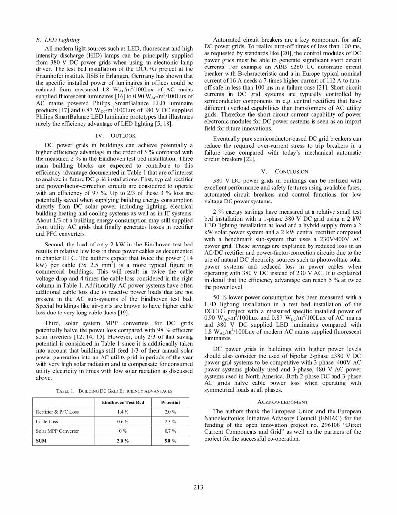
E. LED Lighting All modern light sources such as LED, fluorescent and high
intensity discharge (HID) lamps can be principally supplied from 380 V DC power grids when using an electronic lamp driver. The test bed installation of the DCC+G project at the Fraunhofer institute IISB in Erlangen, Germany has shown that the specific installed power of luminaires in offices could be reduced from measured 1.8 WAC/m2/100Lux of AC mains supplied fluorescent luminaires [16] to 0.90 WAC/m2/100Lux of AC mains powered Philips SmartBalance LED luminaire products [17] and 0.87 WDC/m2/100Lux of 380 V DC supplied Philips SmartBalance LED luminaire prototypes that illustrates nicely the efficiency advantage of LED lighting [5, 18].
IV. OUTLOOK DC power grids in buildings can achieve potentially a
higher efficiency advantage in the order of 5 % compared with the measured 2 % in the Eindhoven test bed installation. Three main building blocks are expected to contribute to this efficiency advantage documented in Table 1 that are of interest to analyze in future DC grid installations. First, typical rectifier and power-factor-correction circuits are considered to operate with an efficiency of 97 %. Up to 2/3 of these 3 % loss are potentially saved when supplying building energy consumption directly from DC solar power including lighting, electrical building heating and cooling systems as well as in IT systems. About 1/3 of a building energy consumption may still supplied from utility AC grids that finally generates losses in rectifier and PFC converters.
Second, the load of only 2 kW in the Eindhoven test bed results in relative low loss in three power cables as documented in chapter III C. The authors expect that twice the power (1.4 kW) per cable (3x 2.5 mm2) is a more typical figure in commercial buildings. This will result in twice the cable voltage drop and 4-times the cable loss considered in the right column in Table 1. Additionally AC power systems have often additional cable loss due to reactive power loads that are not present in the AC sub-systems of the Eindhoven test bed. Special buildings like air-ports are known to have higher cable loss due to very long cable ducts [19].
Third, solar system MPP converters for DC grids potentially halve the power loss compared with 98 % efficient solar inverters [12, 14, 15]. However, only 2/3 of that saving potential is considered in Table 1 since it is additionally taken into account that buildings still feed 1/3 of their annual solar power generation into an AC utility grid in periods of the year with very high solar radiation and to compensate for consumed utility electricity in times with low solar radiation as discussed above.
TABLE 1. BUILDING DC GRID EFFICIENCY ADVANTAGES
Eindhoven Test Bed Potential
Rectifier & PFC Loss 1.4 % 2.0 %
Cable Loss 0.6 % 2.3 %
Solar MPP Converter 0 % 0.7 %
SUM 2.0 % 5.0 %
Automated circuit breakers are a key component for safe DC power grids. To realize turn-off times of less than 100 ms, as requested by standards like [20], the control modules of DC power grids must be able to generate significant short circuit currents. For example an ABB S280 UC automatic circuit breaker with B-characteristic and a in Europe typical nominal current of 16 A needs a 7-times higher current of 112 A to turn-off safe in less than 100 ms in a failure case [21]. Short circuit currents in DC grid systems are typically controlled by semiconductor components in e.g. central rectifiers that have different overload capabilities than transformers of AC utility grids. Therefore the short circuit current capability of power electronic modules for DC power systems is seen as an import field for future innovations.
Eventually pure semiconductor-based DC grid breakers can reduce the required over-current stress to trip breakers in a failure case compared with today’s mechanical automatic circuit breakers [22].
V. CONCLUSION
380 V DC power grids in buildings can be realized with excellent performance and safety features using available fuses, automated circuit breakers and control functions for low voltage DC power systems.
2 % energy savings have measured at a relative small test bed installation with a 1-phase 380 V DC grid using a 2 kW LED lighting installation as load and a hybrid supply from a 2 kW solar power system and a 2 kW central rectifier compared with a benchmark sub-system that uses a 230V/400V AC power grid. These savings are explained by reduced loss in an AC/DC rectifier and power-factor-correction circuits due to the use of natural DC electricity sources such as photovoltaic solar power systems and reduced loss in power cables when operating with 380 V DC instead of 230 V AC. It is explained in detail that the efficiency advantage can reach 5 % at twice the power level.
50 % lower power consumption has been measured with a LED lighting installation in a test bed installation of the DCC+G project with a measured specific installed power of 0.90 WAC/m2/100Lux and 0.87 WDC/m2/100Lux of AC mains and 380 V DC supplied LED luminaires compared with 1.8 WAC/m2/100Lux of modern AC mains supplied fluorescent luminaires.
DC power grids in buildings with higher power levels should also consider the used of bipolar 2-phase ±380 V DC power grid systems to be competitive with 3-phase, 400V AC power systems globally used and 3-phase, 480 V AC power systems used in North America. Both 2-phase DC and 3-phase AC grids halve cable power loss when operating with symmetrical loads at all phases.
ACKNOWLEDGMENT
The authors thank the European Union and the European Nanoelectronics Initiative Advisory Council (ENIAC) for the funding of the open innovation project no. 296108 “Direct Current Components and Grid” as well as the partners of the project for the successful co-operation.
213
REFERENCES [1] European Commission: Directive 2010/31/EU of 19 May 2010 on the
energy performance of buildings, 2010, http://ec.europa.eu/energy/efficiency/buildings/buildings_en.htm
[2] Voss, Musall: Net zero energy buildings, 2nd Edition, 2012, ISBN 978-3-920034-80-5, http://shop.detail.de/de/net-zero-energy-buildings.html
[3] B. Kaempfen: Marche International office building, http://kaempfen.com/en/projekte/neubau/marche-international
[4] Direct Current Components +Grid, European ENIAC Open Innovation project, www.dcc-g.eu
[5] R. Weiss et al: Energy Efficient Low-Voltage DC-Grids for Commercial Buildings, Proceedings of the IEEE International Conference on DC Microgrids 2015
[6] European Telecommunications Standards Institute: Environmental Engineering (EE); Power supply interface at the input to telecommunications and datacom (ICT) equipment; Part 3: Operated by rectified current source, alternating current source or direct current source up to 400 V; Sub-part 1: Direct current source up to 400 V, European Standard ETSI EN 300 132-3-1 V2.1.1, 2012
[7] High Tech Campus Eindhoven: Campus map, http://www.hightechcampus.com/downloads/download/29.api
[8] DRAKA: VULT mb installation cable 0,6/1kV, http://www.drakakabel.nl/producten/datasheet.asp?MofBoomBool=&targetpage=&boom=2000|21151&hoofdstuk=68
[9] Elcontrol: PolarStar, http://www.elcontrol-energy.net/prodotti/schedaprodotto.asp?FAMIGLIA=POLAR STAR
[10] Acrel: PZ 72L-DE DC Power Meter, http://www.acrel.cn/en/ShowProducts.asp?id=24
[11] T.-F. Wu et al: Integration and Operation of a Single-Phase Bidirectional Inverter With Two Buck/Boost MPPTs for DC-Distribution Applications, IEEE Transactions on Power Electronics, No. 11, NOVEMBER 2013
[12] SMA: SUNNY TRIPOWER 12000TL solar inverter, http://www.sma.de/en/products/solarinverters/sunny-tripower-5000tl-12000tl.html
[13] Schneider Electric: C60H-DC automatic circuit breaker, http://www.schneider-electric.com/products/ww/en/1600-din-rail-modular-devices/1655-multi-9-modular-devices/2157-c60h-dc/
[14] W. Yu, J.-S. Lai: Ultra High Efficiency Bidirectional DC-DC Converter With Multi-Frequency Pulse Width Modulation, Proceedings of the IEEE Applied Power Electronic Conference 2008, pp. 1079-1084
[15] Kreutzer, O.; Maerz, M.; Nakata, H., Full SiC DCDC-converter with a Power Density of more than 100kW/dm³, Proceedings of the European Conference on Silicon Carbide & Related Materials, 2014
[16] Zumtobel: Tecton D-ID 2x49W, http://www.zumtobel.com/com-en/products/tecton.html#TECTON decorative optic, indirect/direct distribution
[17] Philips Lighting: SmartBalance suspended LED luminaire, http://www.lighting.philips.com/main/prof/indoor-luminaires/suspended/smartbalance-suspended.html
[18] Fraunhofer Institute for Integrated Systems and Device Technology IISB, http://www.iisb.fraunhofer.de/
[19] Berliner Morgenpost: Kabeltrassen am Flughafen BER werden zum Risiko, in German, January 20th 2014, http://www.morgenpost.de/flughafen-berlin-brandenburg/article124016435/Kabeltrassen-am-Flughafen-BER-werden-zum-Risiko.html
[20] International Electrotecnical Commission: Circuit-breakers for overcurrent protection for household and similar installations - Part 2: Circuit-breakers for a.c. and d.c. operation, Standard IEC 60898-2 ed1.0, 2000
[21] ABB: Miniature circuit-breakers S 280 UC series
[22] K- Sano, M. Takasaki: A Surgeless Solid-State DC Circuit Breaker for Voltage-Source-Converter-Based HVDC Systems, IEEE Transactions on Industry Applications, Vol. 50, No. 4, July/August 2014
214