Embed Size (px)
Citation preview
602IEICE TRANS. COMMUN., VOL.E99–B, NO.3 MARCH 2016
INVITED SURVEY PAPER
Massive MIMO Technologies and Challenges towards 5G
Haralabos PAPADOPOULOS†, Chenwei WANG†, Ozgun BURSALIOGLU†, Xiaolin HOU††, Nonmembers,and Yoshihisa KISHIYAMA†††a), Member
SUMMARY Massive MIMO is widely recognized as an essential tech-nology for 5G. Together with newly allocated spectrum (bandwidth) andnetwork densification (small cells), it is expected to play a key role in cop-ing with the ongoing explosion in data-traffic demand and services. Com-pared to 4G MIMO technologies, massive MIMO can offer large gains incell spectral efficiency, which, in combination with small cells and addi-tional bandwidth, can translate into vast gains in throughput per unit area.We briefly overview the most promising TDD and FDD operation modesfor massive MIMO, and discuss their potential benefits and challenges con-sidering operation over different tiers and frequency bands. TDD operationis naturally suited to massive MIMO and can offer “massive MIMO” gains,with simple in-cell processing, low overheads and low end-to-end latencies.We also briefly describe some important massive MIMO activities towards5G, including standardization efforts, system development and experimen-tal trials.key words: 5G, massive MIMO, TDD, FDD
1. Introduction
The past few decades we have witnessed an explosion inwireless devices and communication modes and services.All these have been enabled by ever evolving wirelessnetworks enabled by novel wireless technologies in com-bination with technology standardization efforts. MIMO(Multiple-Input-Multiple-Output) has been in the forefrontof enabling wireless system technologies, both in theoryand practice. MIMO requires equipping base stations (BS),and possibly, user terminals (UTs) with multiple antennasor antenna elements. A broad range of MIMO techniqueshave been developed over the years that can provide substan-tial benefits with respect to their SISO (Single-Input-Single-Output) counterparts by exploiting transmission and/or re-ception from multiple antennas or antenna elements. At oneend, these include diversity benefits, resulting in improvedcommunication link reliability. At the other end, they in-clude multiplexing gains by simultaneously allowing trans-mission of multiple user streams over the same transmissionresources, thereby increasing the cell spectral efficiency. Asa result, MIMO technologies have been thoroughly stud-
Manuscript received October 7, 2015.Manuscript revised December 14, 2015.†The authors are with DOCOMO Innovations, Inc., Palo Alto,
CA 94304, USA.††The author is with DOCOMO Beijing Labs, Beijing, 100190,
China.†††The author is with NTT DOCOMO, Inc., Yokosuka-shi, 239-
0847 Japan.a) E-mail: [email protected]
DOI: 10.1587/transcom.2015EBI0002
ied and have found application in 3G and 4G systems. Forinstance, LTE-Advanced allows spatial multiplexing up toeight layers for both FDD (frequency-division duplexing)and TDD (time-division duplexing).
The prevalence of smart devices and laptops, and theproliferation of social networking, on-line gaming and mul-timedia on-demand services have led to an explosion indata-traffic in cellular networks, with demands expected tokeep on increasing exponentially. Indeed, as pointed out byCisco’s visual networking index forecast, the global mobiledata traffic is expected to increase approximately 10-foldfrom 2013 to 2018 [3]. Compared to 4G, the 5G systemwould have to deliver substantially higher user peak ratesand system spectral efficiencies per unit area, with signifi-cantly lower end-to-end latencies, enabling at the same timemassive device connectivity, energy savings and cost reduc-tions.
Massive MIMO is widely viewed as one of the founda-tional 5G technologies and is expected to play a key role inachieving the 5G targets. Indeed, it is widely acknowledgedthat the 5G goals will be met by a combination of networkdensification (small cells), additional bandwidth at lowerand/or higher frequency bands, and spectral efficiency in-creases that are to be realized by the use of massive MIMO.
Massive MIMO, originally introduced in the seminalwork of Marzetta [4], [45], also known as “Large-ScaleAntenna Systems”, “Full-Dimension MIMO”, “Very LargeMIMO”, makes a clean break with current practice throughthe use of a large number of antennas at the BSs. Initially theterm massive MIMO was synonymous with a regime wherethe number of antennas grows to infinity. Strictly speaking,there is no clear-cut breakpoint between the conventionaland the massive MIMO regime. In general, however, themassive MIMO regime is usually associated with settingswhere the number of antennas or antenna elements at theBS is several times more than the number of simultaneouslyserved streams [5]–[7].
Compared to conventional MIMO, the excess antennasoffered by massive MIMO help focus energy into smallerregions, incurring thereby low interference levels, so that allUTs can harvest large improvements in throughput and ra-diated energy efficiency. Other benefits of massive MIMOinclude cell range extension, especially in higher frequencybands, higher affinity for Multi-user MIMO (MU-MIMO),near-optimal performance with simple transceivers, analy-sis simplification of UT scheduling owing to channel hard-
Copyright c© 2016 The Institute of Electronics, Information and Communication Engineers
PAPADOPOULOS et al.: MASSIVE MIMO TECHNOLOGIES AND CHALLENGES TOWARDS 5G603
ening and robustness to channel small-scale fading [13],and, equally important, substantial gains in edge-user per-formance [6].
Furthermore, massive MIMO becomes especially at-tractive at higher frequency bands, including millimeterwave (mmWave) bands. Indeed, massive MIMO can beviewed as an enabling technology at higher frequencybands, as large numbers of operational antennas can be read-ily in packed with a small footprint (even at UTs). Theselarge arrays can allow higher power directivity and can com-pensate for the harsh propagation conditions at these bands.
Similar to conventional MIMO, and even more so withmassive MIMO, one of the most important challenges islow-overhead acquisition of channel state information (CSI)at the BS regarding the channels between the massive BSantenna array and the UTs it serves. Indeed with mas-sive MIMO, the CSI acquisition problem is accentuated bythe need to learn a massive number of UT-BS antenna-pairchannels. The overheads of the traditional FDD-based CSIacquisition approach employed by LTE systems (relying onthe use of downlink reference signaling and subsequent CSIfeedback) can become overwhelming in the massive MIMOregime. It was recognized by Marzetta [4] that TDD isthe more natural mode of operation in the massive MIMOregime, as a single uplink pilot per UT allows learning thechannel between the massive array and the user, whether foruplink or downlink data transmission.
In this paper, we present an overview of massiveMIMO technology including cutting-edge research and de-velopment in both academia and industry. This survey paperis organized as follows. We first introduce the fundamen-tal principles and properties of massive MIMO in Sect. 2.In Sect. 3, we provide an overview of the state-of-the art ofmassive MIMO in industry including IEEE and 3GPP stan-dards. In Sect. 4, we briefly describe some important ongo-ing activities towards 5G massive MIMO technologies, and,in particular, focus on the undergoing projects led by NTTDOCOMO. Finally, we conclude this paper in Sect. 5.
2. Overview of Massive MIMO
BSs with large antenna arrays are expected to play a keyrole in coping with the exploding traffic in future wirelessnetworks. Indeed, they promise large-spectral efficiencyincreases, and when used in combination with small cellsand new frequency bands, they can provide large through-put gains per unit area required to meet the exploding trafficdemands.
MIMO technologies exploit the presence of multipleantennas at each BS and/or UTs to provide significant spec-tral efficiency gains. In the context of communicating a sin-gle stream, MIMO enables beam-forming gains via appro-priate spatial filtering at the transmitter (precoding) and/orthe receiver. These beamforming gains can be increasedwith more antenna elements and result in increased effec-tive receiver signal-to-interference plus noise ratio (SINR),and in turn higher spectral efficiencies. More importantly,
MIMO can provide multiplexing gains. Considering, forexample, the downlink (DL) of a cellular system, a BS withmultiple antennas can send multiple streams simultaneouslyto multiple (single or multi-antenna) UTs via MU-MIMO, insuch a way that each UT “sees” and decodes only its desiredstreams.
Massive MIMO takes these attributes to the extreme.Communication of many high-rate streams (many more thanin conventional systems) can be achieved by leveraginglarge-scale antenna arrays at the BS, whereby the numberof antenna elements at the BS is potentially much largerthan the total number of antennas at the UTs. Indeed, asdescribed henceforth in this survey, inserting additional an-tennas at each site does not incur any additional overheadswith the preferred CSI acquisition modes. As a result, theuse of large antenna arrays can result in very large beam-forming gains at each receiver for the desired stream whileat the same time it effectively suppresses interference fromall other transmitted streams.
In addition to the significant performance improve-ments that massive MIMO promises with respect to conven-tional MIMO, there are also a number of additional proper-ties that are unique to massive MIMO. Some of these prop-erties that massive MIMO offer are highlighted in the docu-ment and include the following:
• Large spectral efficiencies: Massive MIMO can simul-taneously create multiple very sharp beams. As a re-sult, many high-rate streams can be multiplexed overthe same transmission resources.• Near-optimal performance with simple transceivers:
Massive arrays allow achieving good performance evenwith a rudimentary precoding technology such as con-jugate beamforming, which ignores multiuser interfer-ence in designing user beams.• Much greener technology: The massive array allows
the creation of sharp beams, directing the radiatedpower to the desired UT. As a result, the radiated powerper bit delivered can be significantly lowered.• Simpler hybrid-ARQ and scheduling: despite the fact
that each user’s channel changes according to its chan-nel’s coherence time and bandwidth, the rates that canbe delivered to the user can be accurately predicted apriori, without knowing the channel small scale fading.• Substantially improved edge-user performance: while
the desired signal at the cell-edge receiver harvests a“massive MIMO” beamforming gain, the interferingsignals coming from the nearby BSs do not have abeamforming gain. As a result, massive MIMO canoffer high SINRs to cell-edge users, in stark contrastto conventional MIMO systems, where cell-edge usersexperience low SINR.• Flexible off-loading and load balancing: Due to the
fact that the large beamforming gain is only experi-enced by the desired signal, the network can serve anedge-user at sufficiently high SINR from any nearbyBS. This allows additional flexibility in balancing the
604IEICE TRANS. COMMUN., VOL.E99–B, NO.3 MARCH 2016
traffic load across the network and can provide largeimprovements in user experience.
As pointed out in the Introduction, CSI is needed at theBS transmitter (CSIT) regarding the channels between theUTs and the massive array at the BS, so as to enable the BSto create sharp beams in the direction of UTs, and achievebeamforming and multiplexing gains. The CSI acquisitionmechanism is an essential piece of massive MIMO as theCSI-acquisition overhead/CSI quality trade-offs directly im-pact the effective massive MIMO performance.
Massive MIMO was originally presented as a macro-cell technology by training in the UL, whether for ULor DL transmission. Indeed, as advocated in [4], operat-ing a massive MIMO macro-cell deployment with reuse-7 and rudimentary precoders and schedulers can in prin-ciple yield a 10-fold improvement in system performancewith respect to the (at the time) state-of-the-art LTE, evenin the presence of mobility. DL operation based on ULtraining leverages radio channel reciprocity, i.e., the factthat the UL and DL radio channels between any pair ofantenna elements are effectively the same, when the twochannels are measured within the coherence time and co-herence bandwidth of the channel. Consequently, UL train-ing based massive MIMO is naturally suited for TDD sys-tems. Training in the UL, whether for UL or DL datatransmission, has been well recognized as the preferredtraining-overhead channel-acquisition method, as a singlepilot from a UT antenna allows training an unlimited num-ber of nearby infrastructure antennas. Many works since[4] have exploited this operation to spatially multiplex largenumbers of users on the same time and frequency resourcesand provide very large aggregate spectral-efficiencies withlow overheads [6]–[9], [12], [14], [29], [30]. Section 2.1presents an overview of massive MIMO schemes with UL-pilot based channel acquisition.
Massive MIMO has also been considered in the con-text of channel acquisition systems of the form deployedin FDD-based LTE, which rely on DL training and ULfeedback. Section 2.2 presents an overview of DL MIMOschemes based on DL training and UL feedback that arespecifically tuned to massive MIMO. Other aspects, in-cluding operation over OFDM and practical implementationconsiderations are briefly considered in Sect. 2.3.
Since the introduction of massive MIMO in [4], manyworks have focused on deployments involving massiveMIMO macro cells. This is partly due to the form fac-tor required for deploying massive arrays at frequenciesin the order of 2 GHz. Another factor was that massiveMIMO macro cells were originally envisioned as a compet-itive cost-effective alternative to network densification andsmall cells [4], [6], [7]. When used in conjunction withsmall cells, however, massive MIMO promises to deliverorders of magnitude higher aggregate spectral efficienciesper unit area. As bands at higher carrier frequencies are ex-pected to become available, it is clear that more and moreantenna elements can be packaged into a small area, mak-
ing it possible to have small cells with large antenna-arrays.A brief overview of some of the challenges and benefits ofmassive MIMO small cells are considered in Sect. 2.4.
2.1 Uplink Pilot Based Massive MIMO
In this section we present an overview of massive MIMOwith uplink pilot based channel acquisition. One key oper-ational assumption is that the channels are learned by ULpilots whether for UL or DL transmission [4]. A single ULpilot transmitted by a UT trains all nearby BS antennas, re-gardless the number of nearby BSs and antennas. This al-lows letting the number of BS antennas M → ∞ without in-creasing overheads. As shown in [4] and subsequent works,significant cell and cell-edge throughput benefits can be har-vested in both the UL and the DL with very simple opera-tion.
Although the focus is on the DL of cellular networks,we also briefly describe selected counterparts for the UL.We make an effort to restate the massive MIMO operationalaspects and rate analysis of key existing works using asmuch as possible a common notation. As a result, the op-eration and achievable-rate formulas presented here can beobtained, albeit at the cost of some effort, by particularizingthe results found in several papers (in particular, see [4]–[7]).
We consider a cellular network with J BSs serving auser populationK . We let M j denote the number of antennaelements at BS j. Without loss of generality, we considersingle-antenna UTs for all the users. It is convenient to firstexpress the basic operation and main results in terms of aslotted system, whereby the transmission resources are par-titioned into slots, or resource blocks, each with N channeluses†. We consider a fixed but arbitrary such slot, and letK j denote the set of active users in cell j, that is, the set ofusers scheduled for data transmission in the given slot byBS j. At first we assume a block-fading model where thechannel between users and BSs remain constant over time-frequency coherence slots of N channel uses, and let hk, j
denote the channel between the single antenna UT of ac-tive user k (in the network) and the M j dimensional array atBS j. The channel vector hk, j captures both large and smallscale fading. In this treatment we present an overview ofthe key techniques, many of which are based on differentchannel models for hk, j. In the context of downlink trans-mission, these techniques rely on radio channel reciprocity,according to which the DL and UL channels between anytwo pairs of antennas are the same. Consequently, hk, j rep-resents both the UL and the DL channels between UT k andthe M j dimensional array at BS j.
2.1.1 Data Transmission Phase
One use of the (complex discrete-time baseband) channel†For instance, in the context of LTE language, a resource block
corresponds to a slot, and the time-frequency elements within aresource block are N channel uses within a slot.
PAPADOPOULOS et al.: MASSIVE MIMO TECHNOLOGIES AND CHALLENGES TOWARDS 5G605
observed at the k-th user receive antenna during the down-link data transmission phase can be represented as
yk =∑j∈J
hTk, jx j + zk, (1)
where x j ∈ CM j is the transmit signal vector of BS j,and zk ∼ CN(0,N0) is the additive Gaussian noise sam-ple at receiver k. The transmitted signals are constrainedby E
[‖x j‖2
]� Pj, where Pj denotes the transmit power of
BS j. BS j sends S j = |K j| downlink data streams, one peractive user (i.e., one stream for each k ∈ K j. With linearMU-MIMO precoding, BS j forms its transmitted signal as
x j =∑k∈K j
vk, juk, (2)
where {uk} are mutually uncorrelated zero-mean data sym-bols with the same per-symbol average energy for all k ∈ K j
(we assume equal power per stream at each BS). We alsouse ν j = S i/M j to denote the spatial load of BS j, that is,the number of downlink streams per BS antenna.
The precoding vectors {vk, j : k ∈ K j} are computedby BS j as a function of the CSI obtained at BS j based onthe uplink pilot transmissions. We focus on two of the mostpopular and well-studied MU-MIMO downlink precodingmethods in the context of massive MIMO: conjugate beam-forming (CBF) and linear zero-forced beamforming (ZFBF)[4]–[7], [45]. However, we remark several other techniqueshave been also considered in the literature, including meth-ods for multi-site precoding, e.g., [8]–[10].
Regarding UL transmission, one use of the (complexdiscrete-time baseband) channel observed at the j-th BS ar-ray can be represented as
yulj =∑�∈J
∑k∈K�
hk, juulk + zul
j , (3)
where uulk is the transmitted information bearing signal
stream from UT k, power constrained to E[‖uul
k ‖2]≤ Pul
for some power level Pul, K� denotes the set of indices ofactive UTs in cell l, and zul
j ∼ CN(0,N0IM j ) represents theadditive noise. For decoding the stream of user k ∈ K j, BSj filters yul
j with an appropriately designed linear filter vk,
yulk = vHh yul
j . (4)
The linear filter vk again is chosen based on CSI col-lected from UL sounding. The most widely common typesof linear front-ends are maximum ratio combining (MRC),the decorrelator and its regularized generalization.
2.1.2 UL Pilot Transmission and Channel Estimation
A subset Q out of the N channel uses within the generic slotis allocated for UL pilot transmission [4]. CSI is obtainedby letting the active users in each cell send their uplink pi-lot signals on the first Q channel uses in each slot. Then,
data transmission (downlink or uplink) takes place in the re-maining N-Q channel uses. Each of the active users in thenetwork is assigned one column of the Q × Q pilot matrix
Φ =[φ1 φ2 · · · φQ
]. (5)
The matrixΦ is a scaled unitary matrix, i.e.,ΦHΦ = QαulI,where αul denotes the transmit power per channel use at aUT in the UL. We index the set of mutually orthogonal pilotsignals φ1, φ2, · · · , φQ by the set Q = {1, 2, . . . ,Q}. We letq(k) denote the pilot index of active user k, i.e., active user kuses pilot φq(k).
Pilot signals are distributed across the BSs such that BSj is given a subset Q( j) ⊆ Q of size |Q( j)| = S j of mutuallyorthogonal pilots (we thus necessarily have S j � Q). In par-ticular, if k ∈ K j, then q(k) ∈ Q( j). Also, we let J (q) ⊆ Jdenote the set of BSs which make use of pilot signal q, i.e.,J (q) = { j ∈ J : q ∈ Q( j)}. The pilot signal allocation, de-fined equivalently by the ensembles of sets {Q( j) : j ∈ J} or{J (q) : q ∈ Q}, can be optimized in some suitable way de-pending on the topology of the network (see for example [6]for a thorough analysis of optimized pilot reuse schemes).The pilot allocations of the type considered here encompassall allocations considered in [4], [6], [7].
The uplink signal block received at BS j during theuplink training phase is given by
Yulj =∑�∈J
∑k∈K�
hk, jφHq(k) + Zul
j , (6)
where Zulj ∈ CM j×Q with i.i.d. elements ∼ CN(0,N0).
We shall consider two types of closely related estima-tors. The first type is based on the CSI estimation approachgiven in [4]: BS j obtains the estimate of the downlink chan-nel vector for user k ∈ K j up to a real positive scaling factorand some bias additive terms known as pilot contaminationby projecting Yul
j along the pilot signal vector φq(k).Pilot contamination is due to the following reason.
Since N is limited by the channel coherence time and band-width, Q cannot be arbitrarily large. Hence, the Q mutuallyorthogonal pilot signals must be reused by several BSs. Inparticular, the CSI estimate for user k ∈ S j, is given by
hk, j =Yul
j φq(k)
‖φq(k)‖2=∑
n:q(n)=q(k)
hn, j + zulk, j, (7)
which contains the linear combination of the channels fromall users k using the same pilot signal q(k) (where users k ∈S j and the other k′ � k are active in other cells) to BS j. Wealso let zul
k, j = Zulj φq(k)‖φq(k)‖−2 denote the projected noise
vector with i.i.d. components ∼ CN(0, ρ−1p ) where ρp �
Qulα
N0.
In computing user SINRs and achievable rates, it isconvenient to consider the well-known MMSE channel es-timates hk, j (whether or not j is the serving BS of user k),based on Yul
j and exploit the estimate-error decomposition
hk, j = hk, j + ek, j (8)
606IEICE TRANS. COMMUN., VOL.E99–B, NO.3 MARCH 2016
with hk, j and ek, j uncorrelated.For instance, in the case that hk, j ∼ CN(0, gk, jI), with
gk, j denoting the large scale gain between UT k and BS j,the MMSE estimator is given by
hk, j = wk, jhk, j (9)
with
wk, j =gk, j
ρ−1p +G(q(k))
j
, (10)
where
G(qo)j =
∑n:q(n)=qo
gn, j. (11)
We also have E[hk, jhHk, j
]= ξk, jI, E
[ek, jeHk, j
]= εk, jI. It will
also prove convenient to express the channel estimate andestimation error power as follows:
ξk, j =gk, j
1 + γ−1k, j
=g2
k, j
ρ−1p +G(q(k))
j
, (12)
εk, j = gk, j − ξk, j = gk, j
1 + γk, j, (13)
where
γk, j =gk, j
ρ−1p +∑
n:q(n)=q(k);n�kgn. j
. (14)
2.1.3 Marzetta’s Insight: Infinite Number of Antennas
Marzetta’s seminal work [4] considered the symmetric set-ting Pj = P, M j = M, and S j = S . He considered sys-tem operation with S fixed and M → ∞ or equivalentlyv j = v = S/M → 0. The only assumption made about theuser channels is that the inner products between the channelsof different users to the same BS satisfy:
1M
hHk, jhn, j → qk, jδk−n (15)
as M ⇒ ∞. The implication is that the magnitude of theinner product between the channels of any two users to thesame BS grows sublinearly with M, that is, it grows slowerthan the norm of the individual user channels. By using onlythis very broad assumption, the massive MIMO operationlimits were derived for the most rudimentary transceivers:CBF in the downlink and MRC in the uplink.
In the DL, Marzetta’s CBF precoding vector for activeuser k ∈ K j at BS j is given by
vCBF-Mk, j =
√αh∗k, j (16)
where the notation “*” represents the complex conjugate ofeach element of its channel vector. The scalar parameterα signifies a power scaling selected commonly across allBSs, chosen so that E
[‖x j‖2
]does not violate the power
constraint Pj = P at BS j for all j. Substituting x j from(2) in (1) with vk, j given by vCBF
k, j in (16) and considering the
signal and interference terms with the spatial load ν → 0(i.e., S fixed and M → ∞), Marzetta derived the followingexpression for the SINR of user k ∈ K j:
SINR∞k, j = limM→∞SINRk, j =
g2k, j∑
�∈J (q(k)):�� jg2
n,�
. (17)
Inspection of (17) reveals that, in the limit of infinite numberof BS antennas, the only impact to the user’s SINR in the DLcomes from pilot contamination, that is, from the fact thatits pilot is reused in other nearby cells in the network. Theeffect of pilot contamination at user k is directly determinedby the sum of the large-scale gains between the user and theset of BSs that operate cells where the pilot of UT k is reusedby another active user.
For UL data transmission, the vector filter v in (4) usedat BS j to project the received vector yul
j in (3) is given by
vMRC ∝ h∗k, j. (18)
Marzetta derived the following expression for the SINR ofuser k ∈ K j:
SINR∞k, j = lim
M→∞SINRulk, j =
g2k, j∑
n:q(n)=q(k)g2
n, j
. (19)
Inspection of (19) reveals that, in the limit of infinite num-ber of BS antennas, the only impact to the user’s SINR inthe UL is also from pilot contamination. The effect of pilotcontamination at user k is different in the UL: it is capturedby the sum of the large scale gains between the user’s serv-ing BS and the set of active users in nearby cells reusing thepilot q(k) of user k. Clearly UL/DL duality does not hold inthis infinite-number-of-antennas massive MIMO regime.
Marzetta used Shannon-type rate expressions [see, e.g.,(21)] based on the limiting SINRs in (17), (19) to study theachievable user-rates and their CDFs in scenarios compris-ing of regular hexagonal cellular macro-cell layouts, withrandomly distributed users and where the large-scale gainsinclude distance-based path-loss and shadowing. Fromthese expressions†, it is clear that the main dimensionalitybottleneck of a massive MIMO cellular system is the num-ber of orthogonal uplink pilot signals Q that can be sent dur-ing a fading coherence block. Since the latter is limited byphysical quantities, such as the Doppler bandwidth and thecoherence bandwidth of the underlying fading random pro-cess, and since channel estimation and downlink pre-codeddata transmission must occur in the same fading coherenceblock, the training dimension directly appears as an over-head cost that limits the overall system spectral efficiency.Marzetta justified his M → ∞ approach, by noting that,while the number of users that can be served by spatial mul-tiplexing by each BS is limited by the number of availableorthogonal pilots, the number of BS antennas is limited onlyby technology constraints (and can be made virtually unlim-ited if the cost of hardware is not taken into account).
†See, e.g., (21) with SINRk, j given by (17).
PAPADOPOULOS et al.: MASSIVE MIMO TECHNOLOGIES AND CHALLENGES TOWARDS 5G607
Simulations in [4] also revealed the extent of pilot con-tamination in the M → ∞ regime. When all Q pilots arereused in every cell, the impact of pilot contamination onthe cell-edge user rates is found to be substantial. To combatpilot contamination conventional frequency reuse-F was ad-vocated, whereby only one every F BS is active in any givenresource block (each assigning all its pilots to Q users). In-deed, reuse-7 can substantially improve the edge-user rates,at the cost, however, of a 3-fold reduction in cell throughput.
While Marzetta’s seminal work [4] makes some keyobservations, it turns out to be somewhat simplistic. Someof the resulting drawbacks of the approach in [4] are:
• The analysis considers the regime of infinite BS anten-nas per user (i.e., M → ∞ with S fixed). As a result,it over-emphasizes the role of pilot contamination asthe sole system bottleneck and leads to the mislead-ing conclusion that CBF is as good as any other lineartechnique, such as ZFBF, in its ability of eliminatingcompletely the intra-cell multiuser interference.• The analysis does not capture the impact of spatial cor-
relation in the user channels. As it turns out, the user-channel spatial correlation can have substantial impli-cations in the actual system design, operation and per-formance.
2.1.4 Achievable Rates for Large but Finite Numbers ofAntennas
Motivated by some of the shortcomings of the analysis andassumptions in the seminal work [4], tools were subse-quently developed in [5]–[7] that enable accurate perfor-mance analysis in more realistic multi-cell settings, wherethe number of antennas at each BS is large but finite. In par-ticular, these works are able to accurately predict the perfor-mance for a given set of (M j, S i), as the limit of a fictitioussetting, where the number of BS antennas and active usersat cell j grow to infinity but at a fixed ratio 1/v j = M j/S j.In this way, the results of [4] are recovered as the specialcase for this ratio going to 0. More important, this type ofanalysis shed light on a much more general regime of an-tennas versus user scaling. It is able to analyze the systemwhen the number of antennas per user is large but finite,which can be regarded as a “practically relevant” massiveMIMO regime. In this overview we focus on the downlinkexpressions. Similar expressions can be readily derived forthe uplink channels.
In all cases the achievable rate (over the N channel usesin the given resource block) of active user k served by BSj based on the observation (1) is captured via a standardachievable bound (that is based on the worst-case uncorre-lated noise) [11], [12]
Rk, j =
(1 − Q
N
)log2(1 + SINRk, j) (20)
where
SINRk, j =E
[|useful signal term|2|{hk,�; � ∈ J}
]
E
[|noise + interference term|2|{hk,�; � ∈ J}
] .
(21)
The “useful signal term” and the “noise + interference term”are with respect to the signal model (1). In particular, the“useful signal term” is given by hTk, jvk j uk while the remain-ing terms in yk comprise the “noise + interference term”.
The value of SINRk, j depends on the precoding methodand system parameters, such as M� and S �, that is, the num-ber of BS antennas and active users at cell l. Using [6],it is shown in [13] that for large M j and a given set of{ν� = S �/M�}, the SINR at active user k served by BS jvia CBF according to (16) is closely approximated by thedeterministic quantity
SINRCBF-Mk, j =
ρ j
ν jq2
k, j
η +∑�∈Jρ�gk,� +
∑�∈J (q(k)):�� j
ρ�ν�g2
k,�
, (22)
where ρ j � Pj/N0, and Pj denotes the transmit power con-straint at BS j within the given slot. The quantity η � 1arises from using an appropriate normalization value of αin (16) that is common to all BSs and is chosen so thetransmit power constraint is not violated at any BS. Wenote that Marzetta’s expression (17) is recovered in the limitν� = ν→ ∞ and with the SNR choice ρ j = ρ.
It is also straightforward [13] to derive the correspond-ing expression with Marzetta’s version of ZFBF. In hisZFBF version, the beam for user k in cell j is created as theconjugate of the projection of the user k channel estimatehk, j in the orthogonal subspace of the channel estimates ofthe other active users in cell j. Specifically, let Hk, j denotethe M j×(S j−1) matrix whose columns comprise the channelestimates of the form (7) of all active users in cell j exceptuser k. Let also Uk, j denote a basis for the orthogonal com-plement of Hk, j, i.e., Uk, j is a unitary M j × (S j − 1) matrixsatisfying UH
k, jUk, j = I and HTk, jUk, j = 0. Then, the associ-
ated ZFBF precoder is given by
vZF-Mk, j =
√αUH
k, jh∗k, j. (23)
Again, much like (16), the scalar parameter α signifies apower scaling selected commonly across all BSs, and is cho-sen so that E
[‖x j‖2
]does not violate the power constraint
Pj = P at BS j for all j.Particularizing the analysis in [6], the SINR at user k
receiver served by BS j for large M j and ν j = S j/M j, isclosely approximated by the deterministic quantity [13]:
SINRZF-Mk, j =
(1 − ν j)ρ j
ν jg2
k, j
1 + ρ−1p ρ j +
∑�∈J�� j
qk,�ρ� +∑�∈J (q(k))
�� j
(1 − ν�)ρ�ν�
g2k,�
.
(24)
608IEICE TRANS. COMMUN., VOL.E99–B, NO.3 MARCH 2016
Comparing (24) with (22), we notice that the effect of ZFBFconsists of decreasing the beamforming gain and the pilotcontamination effect by the quantity (1 − ν j), due to ZF pre-coding. The use of ZFBF, however, also results in reducedintra-cell interference, from gk, jρ j to ρ−1
p ρ j. In the case ofideal channel estimation for instance, the intra-cell interfer-ence with ZFBF is exactly zero.
It is worth making a few additional remarks regarding(22) and (24). First, simple inspection reveals that in thelimit of ν j → 0 for all j, the SINRs with ZFBF and CBF areboth pilot-contamination limited and in fact coincide with(17). Although this confirms the CBF/ZFBF equivalence inthe regime of “sufficiently large” numbers of antennas andfinite number of users per BS [4], this limiting regime isreached with M being many orders of magnitude larger thanS . In general, in the practically large-antenna array regime,ZFBF outperforms CBF significantly. Indeed, as shown in[6], in the practical settings involving 10 s and 100 s of an-tennas, ZFBF can achieve the same performance as CBFusing just a small fraction of the antennas. Furthermore, al-though it is been eluded in [4] that CBF is preferable dueto its lower complexity, it turns out the comparison is notsimple. Indeed when ZFBF and CBF are both designed intheir sweet spots of operation, the computational burden ofZFBF can be similar or even lower than that of CBF† [14].
Simple inspection of (22) and (24) also reveals that ineach case the SINR of user k is decoupled from the channelsof the other active users sharing the same pilot in nearbycells. In stark contrast to conventional MIMO transmission,the rate of active user k with massive MIMO can be pre-dicted a priori, without prior knowledge of the other ac-tive users in its cell and/or other nearby cells and withoutknowledge of the small-scale fading channels. In fact, theexpressions (22) and (24) can be readily used to predict therate that user k would receive from different cells withoutactually scheduling the user for transmission. This fact hasbeen exploited in [13] to develop methods for optimal load-balancing association and user scheduling.
It is also noted that (22) and (24) were derived basedon a precoder operation according to which the power allo-cated to each user stream is effectively proportional to theusers’ large-scale channel gains. SINR expressions can alsobe derived for the equal-power per stream case, which ismuch more attractive in practice†† than proportional powerallocation.
Particularizing the analysis in [6] to the equal-power per stream version of (16), i.e., to the case that
†In the regime of high energy efficiency of an optimized mas-sive MIMO system, the total computational burden of CBF mayexceed that of ZFBF due to the larger number of UTs that CBFtypically serves, and extra computations of the pseudo-inverse forZFBF typically do not dominate the total computational burden.††Indeed, as is well-known, equal-power allocation becomes
asymptotically optimal (with respect to achievable sum-rates) athigh SNR [15]. Proportional power allocation is even less prefer-able from a user-fairness perspective, as less power is allocated tocell-edge users, further reducing their SINRs.
‖vk, j‖2E[|uk |2]= ρ j/S j for all active users in cell j, the
SINR at user k served by BS j is closely approximated bythe deterministic quantity:
SINRCBFk, j =
ρ j
ν jξk, j
1 +∑�∈Jρ�gk,� +
∑�∈J (q(k)):�� j
ρ�ν�ξ�, (25)
where ξk, j is given by (12). Similarly for the equal-powerper stream version of (23), the SINR at user k served by BSj is closely approximated by the quantity:
SINRZFk, j =
1 − ν j
ν jρ jξk, j
1 + εk, jρ j +∑�∈J�� j
gk,�ρ� +∑�∈J (q(k))
�� j
1 − ν�ν�ξk,�ρ�
.
(26)
where εk, j is given by (13).Again, it is worth comparing against the Marzetta’s
M j → ∞ regime, by considering the symmetric case whereSNR j and ν j are identical for all BS, and where ν j = ν =S/M → 0. In the limit ν → 0, the CBF SINR expression(25) also coincides with the ZFBF SINR expression (26).Also, they both converge to the well-known massive MIMOexpression (17) in [4] only in the case that the associatedlarge-scale gains G(q(k))
�in (11) are the same for all l. Again,
although in the limit of ν j → 0 for all j the SINRs withZFBF and CBF coincide [4], in the practical regime involv-ing nonzero spatial loads (finite Mj’s), ZFBF yields substan-tial performance benefits [6]. Indeed comparison of (25)with (26) reveals while the beamforming gain (in both thesignal and pilot-contamination terms) is reduced by a factorof (1− ν j) with ZFBF, the intra-cell interference with ZFBFcan be substantially lower.
Finally it is worth noting that the expressions (25) and(26) are very general and can be used to capture a varietyof different operations in a cellular network. For example,in addition to allowing the treatment of heterogeneous net-works they allow capturing a number of different conven-tional interference-control operations. As an example, con-sider a hexagonal macro-cellular network where each BShas M antennas and Q out of N resource elements in a re-source block have been allocated for training. Expressions(25) and (26) can be used to predict the achievable user rateswith conventional reuse but also with soft reuse by means ofappropriate selection of the {ρ j} and the {S j} sets. Considerfor example conventional reuse with factor F and an averagetransmit power per resource element constraint of Po. In anygiven resource block only a fraction 1/F of BSs are active.Hence, when BS j is active ν j = S/M and ρ j = FPo/No,while when BS j is inactive νi = ρ j = 0. The expressionsalso allow determining the performance in the case of fre-quency reuse one operation, with pilot reuse F. Assumingin this case that Q = FS , BS j is given a subset of S out ofQ pilots fromΦ in (5) while ν j = S/M and ρ j = Po/No.
PAPADOPOULOS et al.: MASSIVE MIMO TECHNOLOGIES AND CHALLENGES TOWARDS 5G609
2.1.5 Reducing the Impact of Pilot Contamination
Although pilot contamination can be mitigated by means ofconventional frequency reuse or pilot reuse, this comes ata significant expense in cell-edge throughput. As a resultseveral works have considered the problem of dealing withthe impact of pilot contamination. One class of approachesinvolves constructing better user-channel estimators [16]–[18].
The work in [16] exploits the eigenvalue decomposi-tion of the sample covariance matrix of the received UL datasignal yUL
j at BS j from (3). Assuming independent userchannels, with hk, j ∼ CN(0, gk, jI), and the gk, j is known(and in the limit M → ∞), each user channel can be (identi-fied) estimated (up to a complex scalar) as one of the eigen-vectors of the sample covariance matrix of the received ULdata signal yUL
j . Knowledge of gk, j allows the BS to com-pute the eigenvalue that is associated with the eigenvector(that is proportional to the channel) of UT k and thus matcheigenvectors with UT channels. For a wide range of systemparameters, the in-cell user channels can be estimated withgreater accuracy than with conventional linear channel esti-mation methods, which are based on observation of UL pilottransmissions.
Similarly to [16], the work in [17] starts with the sin-gular value decomposition of the received signal matrix. Byexploiting results from random matrix theory for large ma-trices, it is shown that pilot contamination is not a funda-mental limitation for massive MIMO systems, if a relativereceive-power margin between in-cell and out-of-cell userscan be provided, e.g., by means of path loss. In that case,the array gain can be utilized to have the accuracy of chan-nel estimation grow unboundedly with the number of an-tennas at polynomial complexity. In particular, the supportof the eigenvalues associated with the in-cell UTs separates(i.e., it is disjoint) from the support of the eigenvalues asso-ciated with the out-of-cell UTs and noise. As a result, thesignal subspace can be readily identified. The received sig-nal is subsequently projected onto an (almost) interference-free subspace, allowing accurate estimation of the in-cellUT channels.
Using Bayesian channel estimation, an improved user-channel estimation method is proposed in [18] that leveragesknowledge of the spatial correlation of the channels of in-cell and out-of-cell users, and under certain conditions caneffectively eliminate the impact of pilot contamination. Inparticular, [18] advocates the use of covariance-aware pi-lot assignment (which requires some coordination amongBSs), exploiting the fact that, in realistic scenarios involvingchannels with finite angular spread, the in-cell and out-of-cell user signals are received at the BS with finite-rank co-variance matrices. The gains provided by this approach areshown to depend on system parameters such as the typicalangle spread measured at the BS and the number of BS an-tennas. Performance close to the interference-free channelestimation scenario is possible even for moderate numbers
of BS antennas.An alternative method for combating pilot contamina-
tion has been considered in [6], [8], which relies on simul-taneously serving users across the network at similar geo-graphic regions with respect to their serving BS. To achievethis, transmission resources are a priori split among a set ofdifferent “colored”’ user-bins across the network so that inany given slot each BS independently schedules users com-ing from the same-color user-bin (or region). This allowsthe possibility of partial pilot signal reuse, where the sameset of orthogonal pilot signals is reused in, e.g., the center ofeach cell, while users at the boundary (which are more proneto inter-cell interference) use extended pilot sets that are or-thogonal across different sectors or cells, thus providing anoption to limit the pilot contamination effect. Each BS binseach user so that users with geographically similar locationsare (and are scheduled) in the same color bin. Consequently,although each BS schedules its user population from the ap-propriate colored bin independently of other BSs, the pre-coder method, the multiplexing gains, and the pilot reusefactor can be independently optimized for each bin color (orregion). Subsequently, SINR expressions were obtained as-suming large but finite numbers of antennas for CBF, ZFBF,and a variety of CoMP-type precoders, which are similarto (25) and (26) [6]. By selecting the transmission schemefor each bin that maximizes the bin spectral efficiency, itwas shown that significant benefits can be harvested withrespect to the single-bin CBF approach in [4] both in termsof (total) cell throughput and cell-edge throughput, therebyeffectively limiting the impact of pilot contamination.
2.1.6 Extensions to Spatially Correlated Channels andCoMP
Several works in the literature have considered additionaltypes of operation such as forms of coordinated multipointtransmission (CoMP) and corresponding performance anal-ysis tools [5]–[7], [10]. Some of these tools also allowpredicting the performance of cellular massive MIMO withspatially correlated channel models [7].
In terms of CoMP, [6] considers the option of localCoMP, where cooperation is restricted to clusters of nearbyBSs. An accurate analysis of the large-system asymptoticperformance is conducted for both CBF and various formsof ZFBF where the ZF constraints are imposed to eliminateintra-cell interference or also some fraction of the inter-cellinterference, by zero-forcing to users at the edge of adja-cent cells. What makes the closed-form analysis possiblein this case is the symmetry in the scheduling accordingto which active user sets are chosen at the cell edges forCoMP transmission. [10] considers an alternative, simpler,distributed form of CoMP, according to which each user isserved by multipoint equal-power transmission from nearbyBSs based on BS precoders that are constructed locally ateach BS, based on local CSI.
In general, however, where the cooperating BSs jointlydesign their precoders for an arbitrary cell-edge user set,
610IEICE TRANS. COMMUN., VOL.E99–B, NO.3 MARCH 2016
there are no closed form expressions for the user SINRs(and corresponding achievable rates). In these cases, theuser SINRs and rates can be closely approximated as thesolution to a fixed-point equation [5], [7]. Although the so-lution is not in closed form, there exist very simple iterativealgorithms, which quickly converge to the solution of thefixed-point equation, yielding the desired user SINRs of thelarge-scale MIMO system.
The method of deterministic equivalent is very power-ful. Not only it allows dealing with a broad range of linearCoMP schemes, but it can also determine the user achiev-able rates taking into account the user-channel spatial corre-lation. In particular, it assumes a channel model whereby thechannel of active user k to BS j in the given slot is a Gaus-sian random vector with arbitrary covariance matrix Rk, j.Letting r = rk, j denote the number of non-zero eigenvaluesof Rk, j the channel of active user k to BS j in the given slotcan be expressed as
hk, j = Uk, jΛ1/2k, j ak, j (27)
where ak, j is an r × 1 vector with i.i.d. CN(0, 1) entries, Λk, j
an r×r diagonal matrix comprising the non-zero eigenvaluesof Rk, j and Uk, j is an M j × r unitary matrix comprising theeigenvectors associated with the r non-zero eigenvalues ofRk, j.
In order to determine the effect of pilot contaminationin the regime of large but finite numbers of antennas, [7]considered in detail one simple example comprising a cell inthe center interfered by a set of surrounding BSs and whereUk,� = Uk for each BS l and the r non-zero eigenvalues ofRk, j are all equal to 1 if l is the user’s serving BS, and areequal to an attenuated value 0 < β < 1 if l is an interferingBS. The important aspect of this example is that r capturesthe richness of the scattering environment (degrees of free-dom in the user channels), which in practice may be differ-ent from M, the number of BS antennas. As shown in [7],the (intra and inter cell) interference experienced by a user(excluding pilot contamination and thermal noise) mainlydepends on the ratio r/S (multiplexing gain per user) anddoes not directly depend on M. Thus, using additional an-tennas at the BS can only reduce interference if the environ-ment provides sufficient scattering so that increasing M alsoincreases the richness of the scattering environment.
2.2 DL Massive MIMO Based on DL Training and CSIFeedback
In this section we focus on DL massive MIMO operationbased on DL training and CSI feedback. In contrast to DLMIMO transmission based on UL training, where the CSI atthe BS is acquired instantly (thereby enabling low-latencyMIMO operation), with DL training, CSI is obtained firstat the UTs, and subsequently fed back to the BS via an ULtransmission. Although this is the MIMO operation usedin LTE FDD systems, supporting it in the context of mas-sive MIMO operation, especially at higher carrier frequen-cies, possesses some key challenges. The inherent delay
in the CSI acquisition operation (due to the need for feed-back) coupled with the fact that accurate CSI is needed forMU MIMO operation, implies that massive MIMO based onDL training can tolerate lower Doppler that its UL-trainingcounterpart. Equally important, unlike UL training wherebya single UL pilot trains all nearby BS antennas (no matterhow many), the overheads do not scale as well with DLtraining. Indeed, the number of channel dimensions thatcan be estimated between each of the active UTs and theBS antenna array are finite, no matter how large an antennaarray is used at the BS. Finally, effective feedback mecha-nisms are needed for massive MIMO, which can provide asufficiently accurate CSI estimate at the BS for enabling MUMIMO operation, while keeping the UL feedback transmis-sion overheads acceptable.
Thankfully, the user-channel spatial correlation can beexploited for improving the efficiency of the DL training op-eration and of the subsequent feedback (in terms of incurredoverheads). Here we briefly describe Joint Spatial Divisionand Multiplexing (JSDM), which is a systematic approachthat exploits the structure of the user-channel correlation inorder to enable DL MU-MIMO with large BS antenna ar-rays and reduced CSI acquisition overheads [20]–[22].
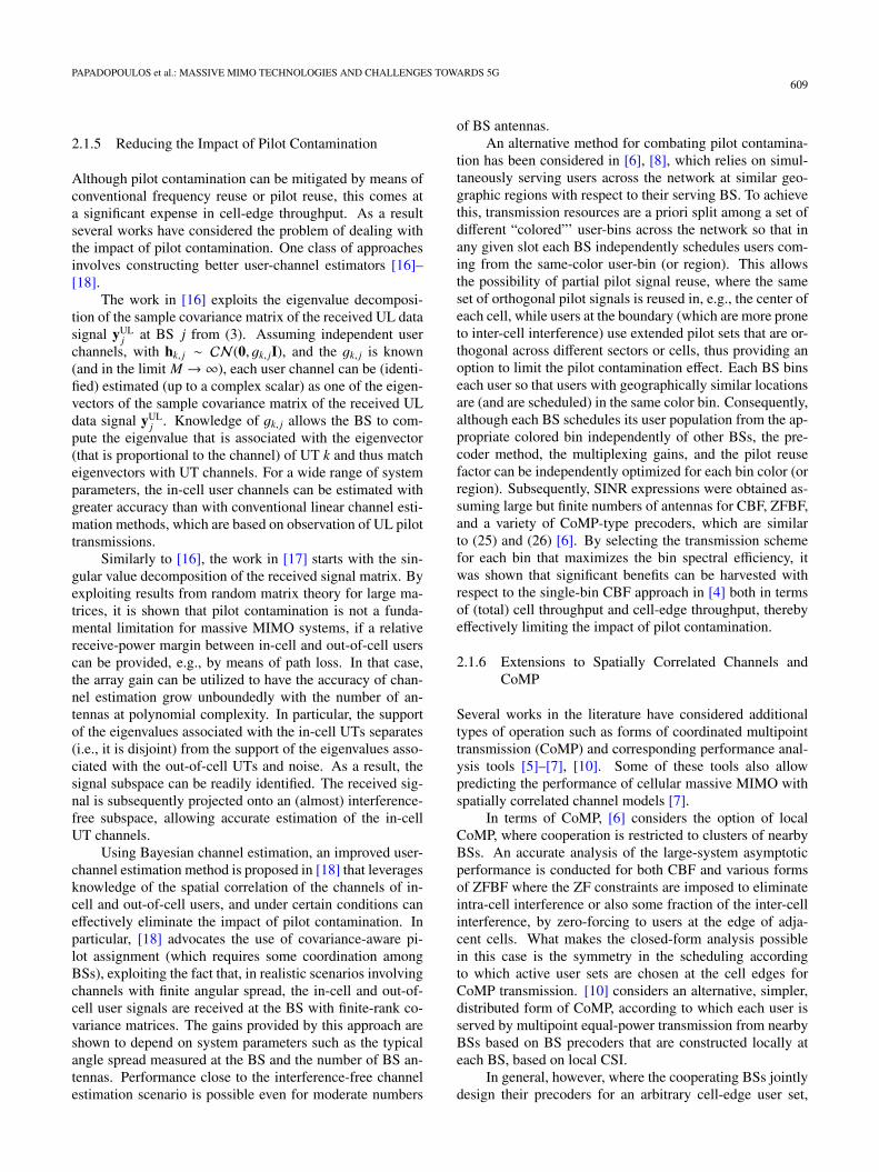
We focus on the simplest and most natural applicationof JSDM, which arises in macro deployments whereby theBS is above the surrounding buildings and structures, andwhere a uniform linear array is used at the BS† [20]. In thiscase, the transmit-antenna correlation can be approximatedvia a one-ring model based on which the transmit covariancefor user k, and its eigen-space decomposition yielding therepresentation (27), becomes a function of the user’s Angleof Arrival (AoA) distribution.
As shown in Fig. 1, with JSDM the active users are(scheduled and) partitioned in groups, such that users in thesame group have nearly similar AoAs while different groups
Fig. 1 An example of JSDM layout with 3D beamforming (Fig. 9 in[20]). The concentric regions are separated by the vertical beamforming.The circles indicate user groups. Same-color groups are served simultane-ously using JSDM.
†The approach readily extends to 2D antenna arrays.
PAPADOPOULOS et al.: MASSIVE MIMO TECHNOLOGIES AND CHALLENGES TOWARDS 5G611
are sufficiently well separated in the AoA domain. JSDMforms the MU-MIMO downlink precoder by concatenatinga pre-beamforming matrix, which depends only on the chan-nel second-order statistics, with a classical multiuser pre-coder, based on the instantaneous knowledge of the resultinglower-dimensionality “effective” channels. Focusing on pre-coder operation in a single generic cell j and assuming thatthe active users in the cell have been partition in G groupsthe precoding signal (2) in JSDM can be expressed in theform
x j =
G∑g=1
Vgug =G∑g=1
BgCgug, (28)
where ug comprises the uk’s of the users in group g. Bg isa (tall) M × bg pre-beamforming matrix used for group gthat is constructed based on second order statistics and it iscommon for all users in group g. Cg is a classical bg × sgMU-MIMO matrix for group g determined based on instan-taneous CSI, with sg denoting the size of user group g andwhere sg � rg. Given that users in the same group havenearly similar AoAs the channels of the sg active users ingroup g from (27) can be compactly re-expressed as
Hg = UgΛ1/2g Ag, (29)
where the sg columns of Hg are the channels of the users ingroup g, and UgΛg are from the eigen-decomposition of the(common) transmit covariance matrix of group g.
Substituting the expression for X j in (28) into (1), wecan compactly represent the received signals of the users ingroup g as
yg = HTgCgugug +
∑g′�g
HTgBg′Cg′ug′ + ng, (30)
where
Hg = BTgHg (31)
denotes the “effective channel” of user group g and ng com-prises all the noise and out-of-cell interference terms experi-enced by the active users in group g. The key design featureof JSDM is that the user groups are scheduled with non-overlapping AoA distributions. This allows designing thepre-beamforming vectors so that
HTgBg′ ≈ 0, for all g′ � g (32)
thereby enabling transmission to group g that is free frominter-group interference. Indeed, considering the specialcase where UH
gUg′ = 0 (any two user-groups have AoA dis-tributions with non-overlapping spatial support), choosingBg = U∗g yields transmission free from inter-group interfer-ence. Hence knowledge of the group effective matrix Hg(reduced CSIT) suffices for MU-MIMO transmission basedon instantaneous CSI on {Hg}.
Equally important, this CSI can be obtained via low-overhead DL training. To illustrate this, consider the casewhere there are sg = s active users per group, rg = r, and b �
r so that (32) holds. In this case the BS requires only b pilotdimensions (resource elements allocated to pilots) to allowall sG active users to estimate their effective channels, i.e.,to allow each active user in group g to estimate the columnof Hg corresponding to its channel. Indeed, let the n-th pilotφn (i.e., the pilot across the BS array over the n-th resourceelement) comprise the sum of the n-th columns of the pre-beamforming matrices {Bg}Gg=1, i.e.,
φn ∝G∑g=1
Bgen
where en is n-th column of a b × b identity matrix. Dueto (32), this pilot transmission allows the users in the g-thgroup to estimate the n-th column of Hg (one entry each).Hence, b pilot transmissions are needed to estimate the ef-fective channel of each active user. Numerical examplesgiven in [20] reveal that an order of magnitude savings canbe harvested with such approaches, both in training andfeedback dimensions.
It is also worth noting that, for large-scale ULAs, thepre-beamforming matrices Bg can be obtained by select-ing blocks of columns of a unitary Discrete Fourier Trans-form (DFT) matrix. Indeed by exploiting the method of de-terministic equivalent [7] and the Toeplitz eigen-subspaceapproximation from [23], DFT pre-beamforming is shownto achieve very good cell and cell-edge throughput perfor-mance with a large reduction in CSI acquisition overheads,requiring only coarse knowledge of each active group’sAoA distribution. The approach is readily extendable to thecase of 2-dimensional ULAs and 3D beamforming, wherebyfixed beams are also created in the elevation angle direction,in addition to the azimuth angle (planar) direction, with thebeamforming matrix taking on the appealing form of a Kro-necker product. In this way, angularly separated groups ofusers in different angular regions in a sector, and at differentdistances from the BS can be served simultaneously.
2.3 Aspects on Practical Operation and Implementations
2.3.1 MIMO Operation over OFDM
The achievable rate characterization in the previous sectionscan be readily translated into a practical OFDM system.To illustrate their mapping we consider here one simpli-fied operational scenario from [4] involving cellular down-link transmission and TDD system operation (based on ULtraining) of the form described in Sect. 2.1. Similar expres-sions can be also readily derived for its FDD counterpartsin Sect. 2.2. Given an OFDM symbol of Ltotal subcarrierswith subcarrier spacing Δ f and a circular prefix length ofTCP = LCP/LtotalΔ f seconds, each OFDM symbol has dura-tion Ts = (Ltotal+LCP)/LtotalΔ f , where “LtotalΔ f ” is the sam-pling frequency. By assuming the user channels do not ex-ceed the circular prefix, TCP, this implies a coherence band-width of Ltotal/L OFDM subcarriers, with L = LCP. Henceknowing the (L + 1)-tap time-domain impulse response of
612IEICE TRANS. COMMUN., VOL.E99–B, NO.3 MARCH 2016
a (vector) user-channel suffices to determine all the OFDMuser channel coefficients over the Ltotal tones for any OFDMsymbol.
The transmission resources on the OFDM plane arepartitioned in resource blocks (RBs) or slots. By assuminga user-channel coherence time of I OFDM symbols, eachRB comprises N′ = (Ltotal/L)I time-frequency resource el-ements (REs) or channel uses, spanning a contiguous set ofL tones and a contiguous set of I OFDM symbols. In partic-ular, assuming a maximum (accommodated) mobile speedof v, I can be found as the largest integer for which userchannel coherence time is given by [53]
ILtotal + LCP �3
4√π foTCP
cv
with fo denoting the carrier frequency and c denoting thespeed of light.
Over the set of RBs spanning a contiguous set of IOFDM symbols each active BS either serves (independentlyof other BSs) a subset of users in each cell, or is silent.Whether or not a BS is active over such a set of RBs span-ning I contiguous OFDM symbols depends on the frequencyreuse pattern; all BSs are active on all RBs with frequencyreuse 1, while for instance with frequency reuse F, one ev-ery F BS is active on all the RBs spanning these I OFDMsymbols.
The UL training - DL data transmission cycle for a setof RBs spanning a contiguous set of OFDM symbols (overall subcarriers) over which a BS is active is as follows. First,τ < I OFDM symbols are entirely used for UL pilots by theUTs in the cell. The next OFDM symbol is also consideredas overhead and serves for allowing the BS to perform therequired processing (estimating the user channels, precod-ing operation, performing other hardware related tasks), andalso allowing a guard band for switching between UL andDL transmission mode. Finally the next I−τ+1 OFDM sym-bols are used by the active BS for MU-MIMO data transmis-sion to its S UTs.
It can be readily verified that within each resourceblock, it is equivalent to the block fading model, where wehave N = (Ltotal/L)(I − 1) channel uses, Q = τ(Ltotal/L),and the achievable rates are given by (20) with Rk, j scaledby I/(I + 1). By taking into account the numerology of theOFDM system, these user achievable rates can be readily ex-ploited to obtain cell-spectral efficiency and cell-throughputexpressions [4].
2.3.2 Simple Resource-Efficient In-Cell Processing
As noted earlier, the massive antenna array can offer “mas-sive MIMO” spectral efficiency gains, with simplified opera-tion with respect to their conventional MIMO counterparts.Even simple precoders with rudimentary power allocationmechanisms can yield large gains with respect to conven-tional MIMO systems. Inspection of the SINR expressions(22) and (24) also reveals that the effective SINR of an ac-tive user does not depend on the identity and the channels of
the other active users simultaneously served by the BS (andin fact they can be predicted a priori), in sharp contrast toconventional MIMO. This allows very simple near optimalscheduling, near-optimal user re-association and admissioncontrol, subject to a broad class of system fairness criteria[13].
Furthermore, massive MIMO also allows reductions inradiated power both in the UL and DL to achieve a desiredSINR level [4]. Many works have consider the potential forpower savings on the uplink and of very large MU-MIMOsystems as a function of the number of BS antennas, activeUTs and precoder method, e.g. [7], [19], [51], [52].
2.3.3 Aspects of Practical Implementations
Many challenges have to be overcome in practice in order todevelop cost-effective reliable massive MIMO implementa-tions that can harvest the gains predicted by theory.
One challenge that arises in exploiting the reciprocity-based DL MU-MIMO operation in Sect. 2.1 is that, whilethe UL/DL radio channels are reciprocal, the transmitterand receiver hardware are not, and introduce time-varyingdistortions in the UL and the DL channels [47]. In sys-tems without built-in self-calibration capability, these non-reciprocal effects of the receiver and transmitter hardwaremust be compensated explicitly via a TDD reciprocity cali-bration protocol. TDD reciprocity was enabled in [47], viaa calibration technique based on exchanging pilots betweenthe BS and UTs. An alternative calibration method, referredto as “Argos,” was presented in [29] as part of an SDR imple-mentation of a TDD reciprocity-based massive MIMO BS.A key advantage of Argos is that it does not require UT par-ticipation. It enables calibration via signaling exchanges andprocessing involving the BS and a reference antenna. Multi-stage calibration methods are developed in [49], which al-low substantially increases in the size of the array that canbe calibrated subject to a given calibration overhead, therebyallowing calibration of massive arrays with small overheads.
Enabling reciprocity-based CoMP MU-MIMO trans-mission with low-cost hardware is even more challenging,as there is a need for synchronization of non-collocated an-tenna elements driven by different clocks, and the calibra-tion schemes for collocated antennas do not suffice. In [48]calibration methods were presented, which offer substan-tial calibration improvements with respect to Argos. Also,[48] develops signaling protocols and methods for synchro-nization, which together with the calibration methods en-able reciprocity-based CoMP MU-MIMO transmission withlow-cost hardware.
2.4 Massive MIMO Small Cells
Early on in the quest for 5G system designs, it became ev-ident that there are two main approaches for substantiallyimproving the network spectral efficiency per unit area (withrespect to 4G systems): massive MIMO arrays and smallcell densification.
PAPADOPOULOS et al.: MASSIVE MIMO TECHNOLOGIES AND CHALLENGES TOWARDS 5G613
In massive MIMO, each BS is equipped with a large-scale antenna array in linear, patched, cylindrical, or otherpreferred shapes, and the antenna elements are deployedcentrally. In contrast, in small cell networks, there are anumber of micro cells with limited number of antennas.These small cells can be used either to increase the cell cov-erage, particularly the cell edge areas, or to divide a regularcell into many small cells so that the BS in each small cellcan serve a small number of UTs. Thus, they seem to resultin two opposing ideas: concentrating the antennas to formmassive MIMO BSs, and distributing the antennas to formdisjoint small cells. Is this perception true?
While there have been indeed many works in the liter-ature studying and even comparing the performance of mas-sive MIMO and small cells, in 5G networks, these two ideasare essentially not opposite but can be symbiotic for tworeasons. First, although densification of small cells short-ens the distance between the UTs and interfering BSs, theresulting less inter-cell interference pass-loss could be com-bated by the massive antenna array gain offered by massiveMIMO in its own cell; Second, if we explore higher fre-quency bands, e.g., mmWave bands above 30 GHz, to avoidovercrowded frequency band allocation in regular bands, theincreased inter-cell interference caused by small cell densifi-cation could also be neutralized by increased pass-loss and,if necessary, appropriate interference management.
To study the performance gain of massive MIMO insmall cells, we can directly apply the math that we developin prior sections. Specifically, the UL-training operationand expressions derived in Sect. 2.1 are not particular tomacro deployments but can also be directly applied to mas-sive MIMO small cells. One such approach is described in[13]. By assuming a pilot reuse factor F, the pilots set Φin (5) are split into F ≥ 4 disjoint groups. Using a coloringassignment of F colors (one color per set of pilots), the col-ors (colored sets of pilots) are assigned to cells across thenetwork so that no two neighboring cells are assigned thesame color (Otherwise, they would have to share the samepilot set). Then the rate performance over the small cells(with local user scheduling) can be directly inferred fromthe SINR expressions in (22) and (24). Inspection for in-stance, of (24), reveals that each BS can predict the peakrate it can provide to its users without requiring knowledgeof the scheduling decisions at the other BSs. This decou-pling effect can be readily used at each BS for schedulingdecisions and by the network for user re-association deci-sions and admission control [13].
In the remainder of this section we briefly considerother important aspects of massive MIMO small cells, in-cluding macro-assisted operation, performance evaluationsin hot spots with cellular and CoMP transmission, and oper-ation over higher frequencies.
2.4.1 Macro-assisted Small Cell Deployment with Direc-tional Antenna Array
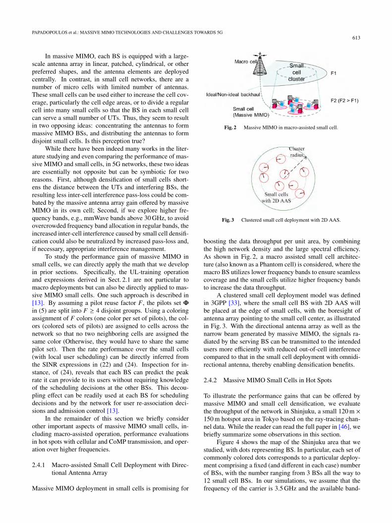
Massive MIMO deployment in small cells is promising for
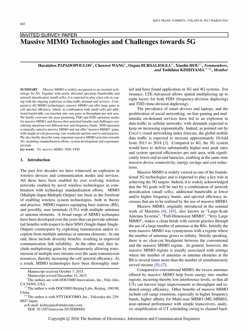
Fig. 2 Massive MIMO in macro-assisted small cell.
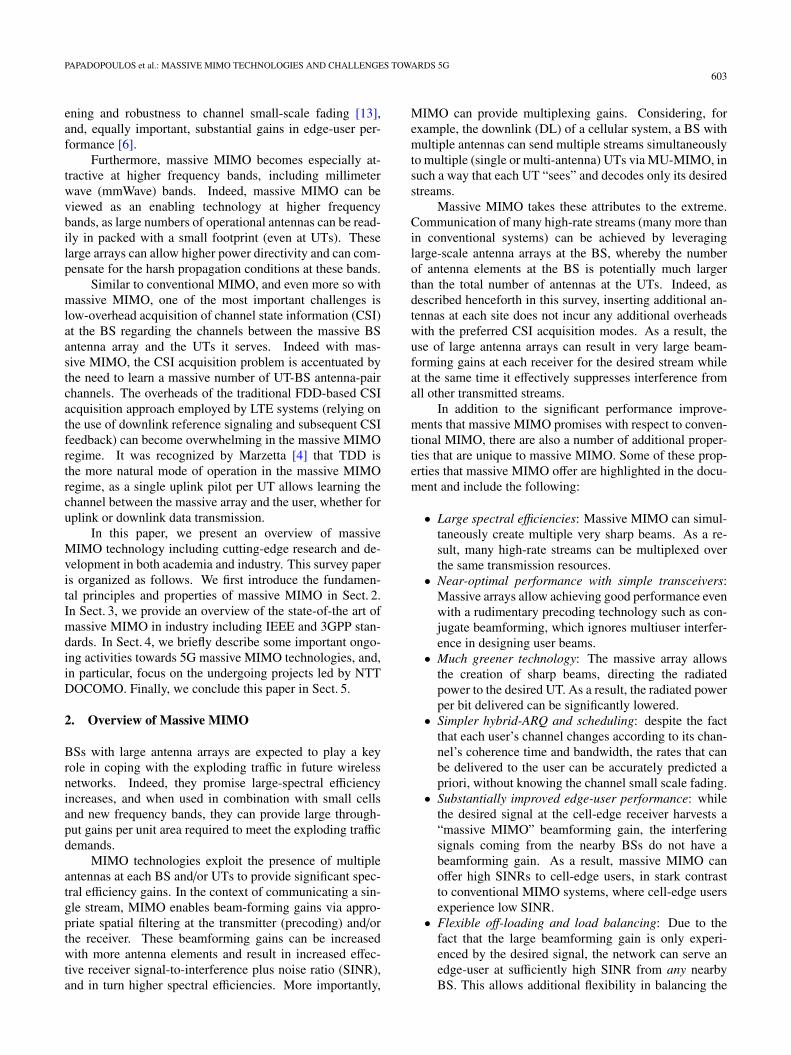
Fig. 3 Clustered small cell deployment with 2D AAS.
boosting the data throughput per unit area, by combiningthe high network density and the large spectral efficiency.As shown in Fig. 2, a macro assisted small cell architec-ture (also known as a Phantom cell) is considered, where themacro BS utilizes lower frequency bands to ensure seamlesscoverage and the small cells utilize higher frequency bandsto increase the data throughput.
A clustered small cell deployment model was definedin 3GPP [33], where the small cell BS with 2D AAS willbe placed at the edge of small cells, with the boresight ofantenna array pointing to the small cell center, as illustratedin Fig. 3. With the directional antenna array as well as thenarrow beam generated by massive MIMO, the signals ra-diated by the serving BS can be transmitted to the intendedusers more efficiently with reduced out-of-cell interferencecompared to that in the small cell deployment with omnidi-rectional antenna, thereby enabling densification benefits.
2.4.2 Massive MIMO Small Cells in Hot Spots
To illustrate the performance gains that can be offered bymassive MIMO and small cell densification, we evaluatethe throughput of the network in Shinjuku, a small 120 m ×150 m hotspot area in Tokyo based on the ray-tracing chan-nel data. While the reader can read the full paper in [46], webriefly summarize some observations in this section.
Figure 4 shows the map of the Shinjuku area that westudied, with dots representing BS. In particular, each set ofcommonly colored dots corresponds to a particular deploy-ment comprising a fixed (and different in each case) numberof BSs, with the number ranging from 3 BSs all the way to12 small cell BSs. In our simulations, we assume that thefrequency of the carrier is 3.5 GHz and the available band-
614IEICE TRANS. COMMUN., VOL.E99–B, NO.3 MARCH 2016
Fig. 4 BSs deployment in Shinjuku, Tokyo (Fig. 12 in [46]).
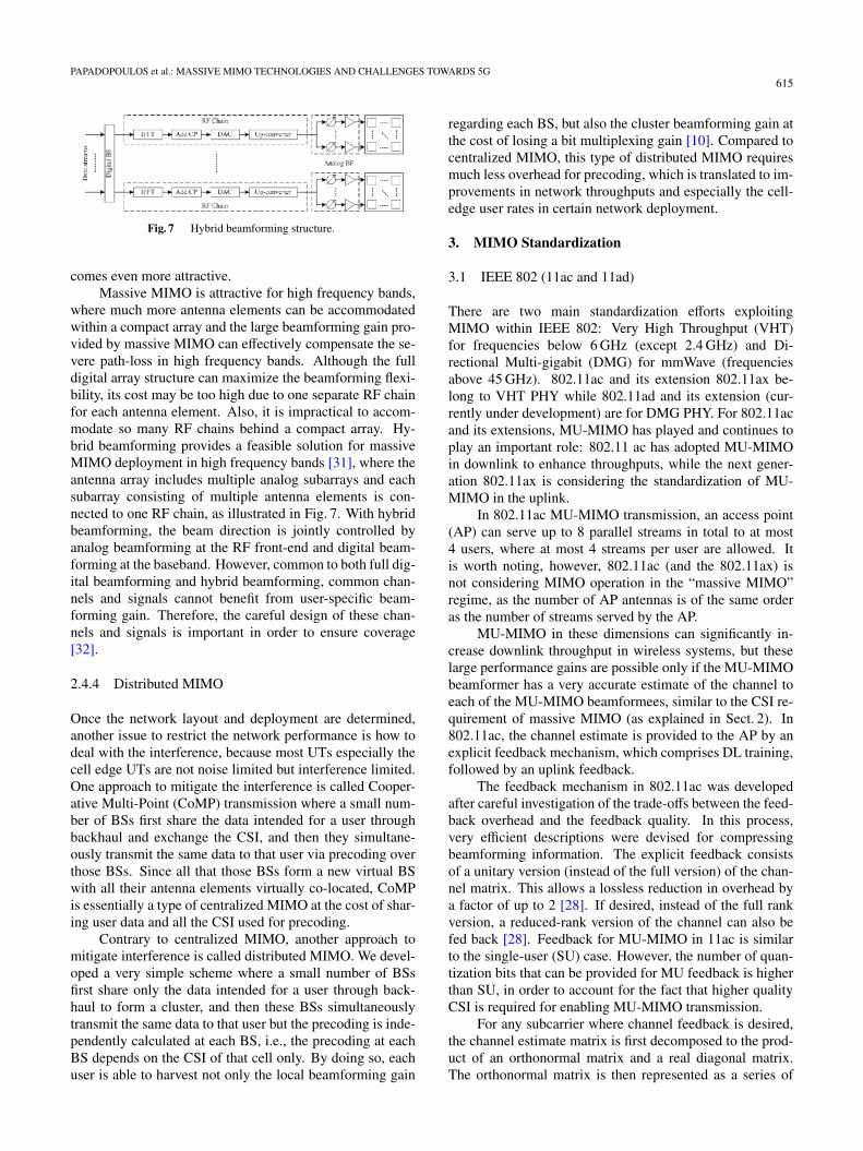
Fig. 5 Network throughput by using ZFBF at BSs regarding the numberof antennas at each BS (Fig. 13(b) in [46]).
width is 20 MHz.By assuming that 6 BSs are turned on, Fig. 5 shows the
network throughout performance regarding the number ofantennas equipped at each BS for three schemes. In partic-ular, the green curve represents the performance of single-user beamforming at each BS where the BS only serves oneuser at each time. Note that in the case that the number ofantennas equals to 1 this transmission mode reduces to SISOpoint-to-point transmission. The red and blue curves repre-sent the performance of MU-MIMO where each BS serves4 and 8 users respectively via ZFBF and equal power alloca-tion per stream. Each UT is associated to the BS from whichit has experiences the highest received signal strength. EachBS serves it users via round robin scheduling. It can be eas-ily seen that the throughput increases substantially when thenumber of antennas grows, and the throughput gain is evenlarger when MU-MIMO is incorporated.
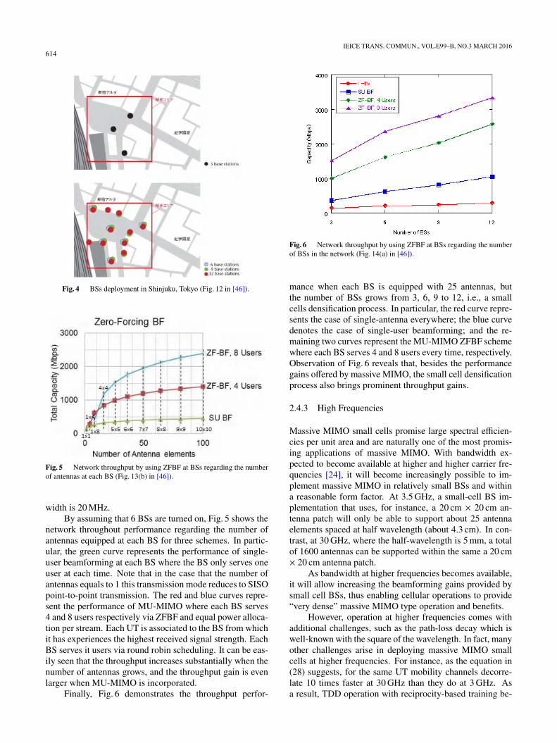
Finally, Fig. 6 demonstrates the throughput perfor-
Fig. 6 Network throughput by using ZFBF at BSs regarding the numberof BSs in the network (Fig. 14(a) in [46]).
mance when each BS is equipped with 25 antennas, butthe number of BSs grows from 3, 6, 9 to 12, i.e., a smallcells densification process. In particular, the red curve repre-sents the case of single-antenna everywhere; the blue curvedenotes the case of single-user beamforming; and the re-maining two curves represent the MU-MIMO ZFBF schemewhere each BS serves 4 and 8 users every time, respectively.Observation of Fig. 6 reveals that, besides the performancegains offered by massive MIMO, the small cell densificationprocess also brings prominent throughput gains.
2.4.3 High Frequencies
Massive MIMO small cells promise large spectral efficien-cies per unit area and are naturally one of the most promis-ing applications of massive MIMO. With bandwidth ex-pected to become available at higher and higher carrier fre-quencies [24], it will become increasingly possible to im-plement massive MIMO in relatively small BSs and withina reasonable form factor. At 3.5 GHz, a small-cell BS im-plementation that uses, for instance, a 20 cm × 20 cm an-tenna patch will only be able to support about 25 antennaelements spaced at half wavelength (about 4.3 cm). In con-trast, at 30 GHz, where the half-wavelength is 5 mm, a totalof 1600 antennas can be supported within the same a 20 cm× 20 cm antenna patch.
As bandwidth at higher frequencies becomes available,it will allow increasing the beamforming gains provided bysmall cell BSs, thus enabling cellular operations to provide“very dense” massive MIMO type operation and benefits.
However, operation at higher frequencies comes withadditional challenges, such as the path-loss decay which iswell-known with the square of the wavelength. In fact, manyother challenges arise in deploying massive MIMO smallcells at higher frequencies. For instance, as the equation in(28) suggests, for the same UT mobility channels decorre-late 10 times faster at 30 GHz than they do at 3 GHz. Asa result, TDD operation with reciprocity-based training be-
PAPADOPOULOS et al.: MASSIVE MIMO TECHNOLOGIES AND CHALLENGES TOWARDS 5G615
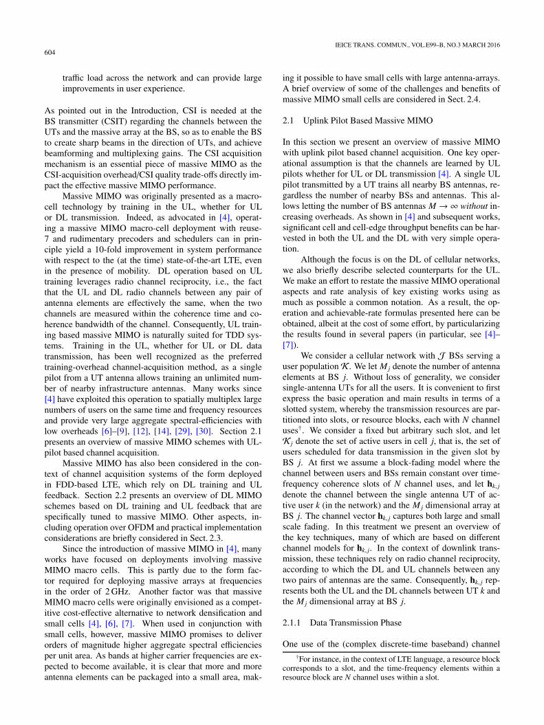
Fig. 7 Hybrid beamforming structure.
comes even more attractive.Massive MIMO is attractive for high frequency bands,
where much more antenna elements can be accommodatedwithin a compact array and the large beamforming gain pro-vided by massive MIMO can effectively compensate the se-vere path-loss in high frequency bands. Although the fulldigital array structure can maximize the beamforming flexi-bility, its cost may be too high due to one separate RF chainfor each antenna element. Also, it is impractical to accom-modate so many RF chains behind a compact array. Hy-brid beamforming provides a feasible solution for massiveMIMO deployment in high frequency bands [31], where theantenna array includes multiple analog subarrays and eachsubarray consisting of multiple antenna elements is con-nected to one RF chain, as illustrated in Fig. 7. With hybridbeamforming, the beam direction is jointly controlled byanalog beamforming at the RF front-end and digital beam-forming at the baseband. However, common to both full dig-ital beamforming and hybrid beamforming, common chan-nels and signals cannot benefit from user-specific beam-forming gain. Therefore, the careful design of these chan-nels and signals is important in order to ensure coverage[32].
2.4.4 Distributed MIMO
Once the network layout and deployment are determined,another issue to restrict the network performance is how todeal with the interference, because most UTs especially thecell edge UTs are not noise limited but interference limited.One approach to mitigate the interference is called Cooper-ative Multi-Point (CoMP) transmission where a small num-ber of BSs first share the data intended for a user throughbackhaul and exchange the CSI, and then they simultane-ously transmit the same data to that user via precoding overthose BSs. Since all that those BSs form a new virtual BSwith all their antenna elements virtually co-located, CoMPis essentially a type of centralized MIMO at the cost of shar-ing user data and all the CSI used for precoding.
Contrary to centralized MIMO, another approach tomitigate interference is called distributed MIMO. We devel-oped a very simple scheme where a small number of BSsfirst share only the data intended for a user through back-haul to form a cluster, and then these BSs simultaneouslytransmit the same data to that user but the precoding is inde-pendently calculated at each BS, i.e., the precoding at eachBS depends on the CSI of that cell only. By doing so, eachuser is able to harvest not only the local beamforming gain
regarding each BS, but also the cluster beamforming gain atthe cost of losing a bit multiplexing gain [10]. Compared tocentralized MIMO, this type of distributed MIMO requiresmuch less overhead for precoding, which is translated to im-provements in network throughputs and especially the cell-edge user rates in certain network deployment.
3. MIMO Standardization
3.1 IEEE 802 (11ac and 11ad)
There are two main standardization efforts exploitingMIMO within IEEE 802: Very High Throughput (VHT)for frequencies below 6 GHz (except 2.4 GHz) and Di-rectional Multi-gigabit (DMG) for mmWave (frequenciesabove 45 GHz). 802.11ac and its extension 802.11ax be-long to VHT PHY while 802.11ad and its extension (cur-rently under development) are for DMG PHY. For 802.11acand its extensions, MU-MIMO has played and continues toplay an important role: 802.11 ac has adopted MU-MIMOin downlink to enhance throughputs, while the next gener-ation 802.11ax is considering the standardization of MU-MIMO in the uplink.
In 802.11ac MU-MIMO transmission, an access point(AP) can serve up to 8 parallel streams in total to at most4 users, where at most 4 streams per user are allowed. Itis worth noting, however, 802.11ac (and the 802.11ax) isnot considering MIMO operation in the “massive MIMO”regime, as the number of AP antennas is of the same orderas the number of streams served by the AP.
MU-MIMO in these dimensions can significantly in-crease downlink throughput in wireless systems, but theselarge performance gains are possible only if the MU-MIMObeamformer has a very accurate estimate of the channel toeach of the MU-MIMO beamformees, similar to the CSI re-quirement of massive MIMO (as explained in Sect. 2). In802.11ac, the channel estimate is provided to the AP by anexplicit feedback mechanism, which comprises DL training,followed by an uplink feedback.
The feedback mechanism in 802.11ac was developedafter careful investigation of the trade-offs between the feed-back overhead and the feedback quality. In this process,very efficient descriptions were devised for compressingbeamforming information. The explicit feedback consistsof a unitary version (instead of the full version) of the chan-nel matrix. This allows a lossless reduction in overhead bya factor of up to 2 [28]. If desired, instead of the full rankversion, a reduced-rank version of the channel can also befed back [28]. Feedback for MU-MIMO in 11ac is similarto the single-user (SU) case. However, the number of quan-tization bits that can be provided for MU feedback is higherthan SU, in order to account for the fact that higher qualityCSI is required for enabling MU-MIMO transmission.
For any subcarrier where channel feedback is desired,the channel estimate matrix is first decomposed to the prod-uct of an orthonormal matrix and a real diagonal matrix.The orthonormal matrix is then represented as a series of
616IEICE TRANS. COMMUN., VOL.E99–B, NO.3 MARCH 2016
Givens rotations [27], and the parameters of the rotations areuniformly quantized [28]. An example to illustrate Givensrotations for a single antenna beamformee and a 3-antennabeamformer is provided in [28]. In this example for a singlesubcarrier 34 feedback bits is required.
Applying the 802.11ac explicit feedback mechanismto massive MIMO deployments is, however, not practical.As we mentioned earlier, first, the number of feedback bitsrequired by givens transformations becomes prohibitive forlarge antenna arrays. In addition, DL training overheads be-come prohibitive, as the overheads scale linearly with thenumber of transmit antennas.
Another standardization effort within IEEE 802 is forthe PHY layer in mmWave by 802.11ad and its exten-sions. 802.11ad operates at roughly an order of magnitudehigher carrier frequencies compared to 802.11ac/ax (anduses roughly an order of magnitude more bandwidth). Aslarge-antenna arrays can be packed into a small design atmmWave, in 802.11ad channel training mechanisms are inplace so as to enable large RX/TX beamforming gains tocompensate for the harsh path-loss. Hence the envisionedoperation for 802.11ad is in fact in the massive MIMOregime. IEEE 802 PHY layer standardization at these higherfrequencies, however, is at its infancy. Indeed, 802.11adonly considers single-stream transmission, targeting staticusers in Line-Of-Sight (LOS) environments. This is be-cause in these higher-frequency bands, channels decorrelatea lot faster and the path-loss is much harsher. Currently, ex-tensions of 11ad are under consideration, called 802.11ay,which targets beam-steering and multi-stream operation innon-LOS (NLOS) environments.
3.2 3GPP
MIMO has been one of the key technologies since the firstrelease of 3GPP LTE, i.e., LTE Rel. 8. Until LTE Rel. 12,the LTE specifications only focus on the one dimensional(1D) antenna array and the maximum number of supportableantenna ports is 8, which is far from being massive MIMO.
Before the standardization work for a larger (than 8 an-tenna ports) antenna array, 3GPP carried out two prereq-uisite study items (SIs), i.e., the RAN4 SI for active an-tenna array system (AAS) [34] and the RAN1 SI for three-dimensional (3D) channel model [35].
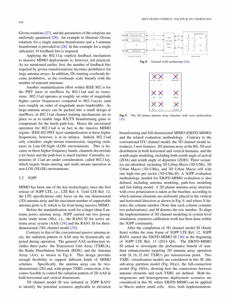
Contrary to that of the conventional passive antenna ar-ray, the radiation pattern of AAS may be dynamically ad-justed during operation. The general AAS architecture in-cludes three parts: the Transceiver Unit Array (TXRUA),the Radio Distribution Network (RDN), and the AntennaArray (AA), as shown in Fig. 8. This design providesenough flexibility to support different kinds of MIMOschemes. Specifically, the antenna array can be two-dimensional (2D) and, with proper TXRU connection, it be-comes feasible to control the radiation pattern of 2D AAS inboth horizontal and vertical dimensions.
3D channel model SI was initiated in 3GPP RAN1to identify the potential scenarios applicable to elevation
Fig. 8 General AAS architecture [34].
Fig. 9 The 2D planar antenna array structure with cross polarization[35].
beamforming and full-dimensional MIMO (EB/FD-MIMO)and the related evaluation methodology. Contrary to theconventional ITU channel model, the 3D channel model in-troduces 3 new features: 2D antenna array at the BS, 3D userdistribution in both horizontal and vertical domains, and thezenith angle modeling, including both zenith angle of arrival(ZOA) and zenith angle of departure (ZOD). Three scenar-ios are identified, including 3D Urban Micro (3D-UMi), 3DUrban Macro (3D-UMa), and 3D Urban Macro cell withone high-rise per sector (3D-UMa-H). A 3GPP evaluationmethodology needed for EB/FD-MIMO evaluation is alsodefined, including antenna modeling, path-loss modelingand fast fading model. A 2D planar antenna array structurewith cross polarization is taken as the baseline, according towhich antenna elements are uniformly placed in the verticaland horizontal direction as shown in Fig. 9, and where N de-notes the column number (Note that each column containstwo polarizations), and M denotes the row number. To alignthe implementation of 3D channel modeling in system levelsimulation, extensive calibration work has been done withinthe 3GPP community.
After the completion of 3D channel model SI (StudyItem) within the time frame of 3GPP LTE Rel. 12, 3GPPRAN1 started the EB/FD-MIMO SI [36] at the beginningof 3GPP LTE Rel. 13 (2014 Q4). The EB/FD-MIMOSI aimed to investigate the performance benefit of stan-dard enhancements targeting 2D antenna array operationwith {8, 16, 32, 64} TXRUs per transmission point. TwoTXRU virtualization models are considered in this SI: ithesub-array partition model (Fig. 10(a)); the full-connectionmodel (Fig. 10(b)), showing how the connections betweenantenna elements and each TXRU are defined. Both ho-mogeneous and heterogeneous deployment scenarios areconsidered in this SI, where EB/FD-MIMO can be appliedto Macro and/or small cells. Also, both implementation-
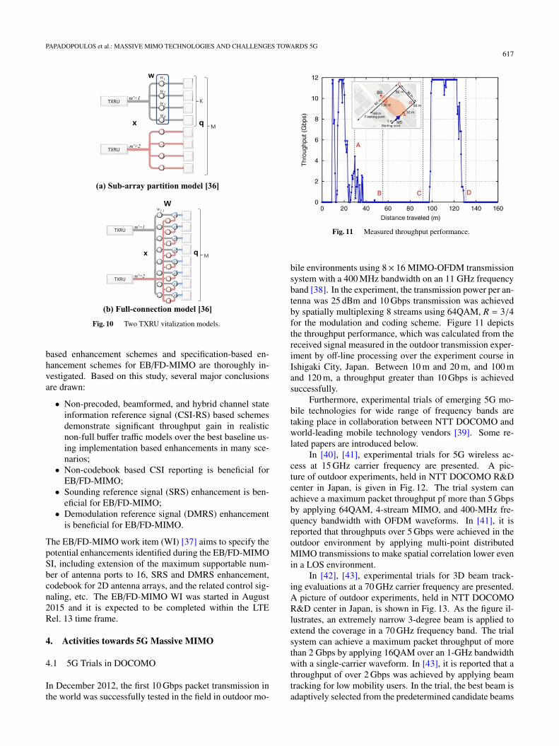
PAPADOPOULOS et al.: MASSIVE MIMO TECHNOLOGIES AND CHALLENGES TOWARDS 5G617
Fig. 10 Two TXRU vitalization models.
based enhancement schemes and specification-based en-hancement schemes for EB/FD-MIMO are thoroughly in-vestigated. Based on this study, several major conclusionsare drawn:
• Non-precoded, beamformed, and hybrid channel stateinformation reference signal (CSI-RS) based schemesdemonstrate significant throughput gain in realisticnon-full buffer traffic models over the best baseline us-ing implementation based enhancements in many sce-narios;• Non-codebook based CSI reporting is beneficial for
EB/FD-MIMO;• Sounding reference signal (SRS) enhancement is ben-
eficial for EB/FD-MIMO;• Demodulation reference signal (DMRS) enhancement
is beneficial for EB/FD-MIMO.
The EB/FD-MIMO work item (WI) [37] aims to specify thepotential enhancements identified during the EB/FD-MIMOSI, including extension of the maximum supportable num-ber of antenna ports to 16, SRS and DMRS enhancement,codebook for 2D antenna arrays, and the related control sig-naling, etc. The EB/FD-MIMO WI was started in August2015 and it is expected to be completed within the LTERel. 13 time frame.
4. Activities towards 5G Massive MIMO
4.1 5G Trials in DOCOMO
In December 2012, the first 10 Gbps packet transmission inthe world was successfully tested in the field in outdoor mo-
Fig. 11 Measured throughput performance.
bile environments using 8× 16 MIMO-OFDM transmissionsystem with a 400 MHz bandwidth on an 11 GHz frequencyband [38]. In the experiment, the transmission power per an-tenna was 25 dBm and 10 Gbps transmission was achievedby spatially multiplexing 8 streams using 64QAM, R = 3/4for the modulation and coding scheme. Figure 11 depictsthe throughput performance, which was calculated from thereceived signal measured in the outdoor transmission exper-iment by off-line processing over the experiment course inIshigaki City, Japan. Between 10 m and 20 m, and 100 mand 120 m, a throughput greater than 10 Gbps is achievedsuccessfully.
Furthermore, experimental trials of emerging 5G mo-bile technologies for wide range of frequency bands aretaking place in collaboration between NTT DOCOMO andworld-leading mobile technology vendors [39]. Some re-lated papers are introduced below.
In [40], [41], experimental trials for 5G wireless ac-cess at 15 GHz carrier frequency are presented. A pic-ture of outdoor experiments, held in NTT DOCOMO R&Dcenter in Japan, is given in Fig. 12. The trial system canachieve a maximum packet throughput pf more than 5 Gbpsby applying 64QAM, 4-stream MIMO, and 400-MHz fre-quency bandwidth with OFDM waveforms. In [41], it isreported that throughputs over 5 Gbps were achieved in theoutdoor environment by applying multi-point distributedMIMO transmissions to make spatial correlation lower evenin a LOS environment.
In [42], [43], experimental trials for 3D beam track-ing evaluations at a 70 GHz carrier frequency are presented.A picture of outdoor experiments, held in NTT DOCOMOR&D center in Japan, is shown in Fig. 13. As the figure il-lustrates, an extremely narrow 3-degree beam is applied toextend the coverage in a 70 GHz frequency band. The trialsystem can achieve a maximum packet throughput of morethan 2 Gbps by applying 16QAM over an 1-GHz bandwidthwith a single-carrier waveform. In [43], it is reported that athroughput of over 2 Gbps was achieved by applying beamtracking for low mobility users. In the trial, the best beam isadaptively selected from the predetermined candidate beams
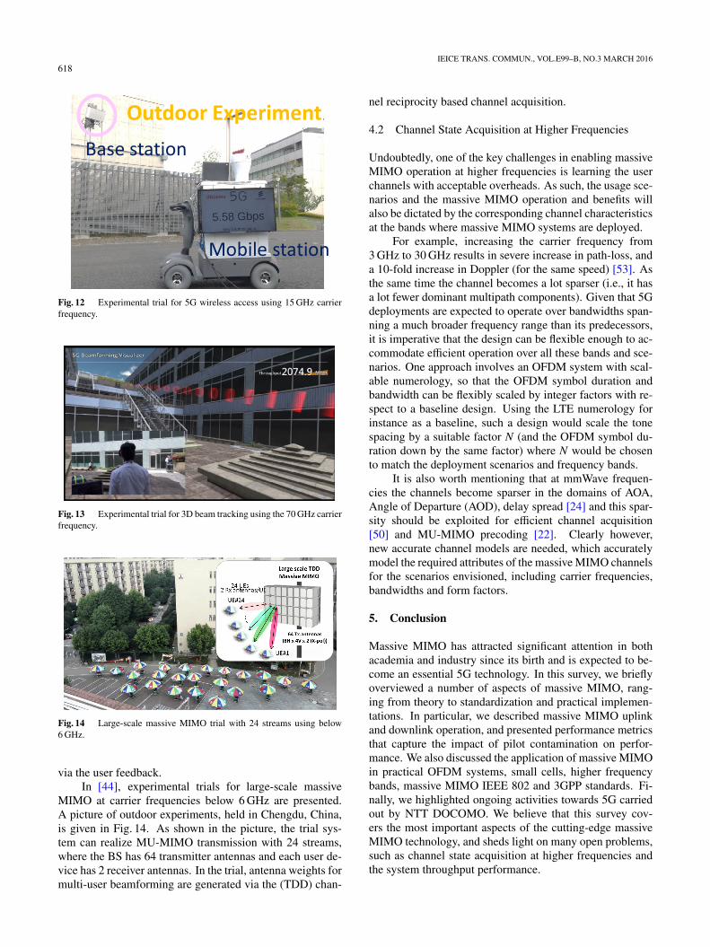
618IEICE TRANS. COMMUN., VOL.E99–B, NO.3 MARCH 2016
Fig. 12 Experimental trial for 5G wireless access using 15 GHz carrierfrequency.
Fig. 13 Experimental trial for 3D beam tracking using the 70 GHz carrierfrequency.
Fig. 14 Large-scale massive MIMO trial with 24 streams using below6 GHz.
via the user feedback.In [44], experimental trials for large-scale massive
MIMO at carrier frequencies below 6 GHz are presented.A picture of outdoor experiments, held in Chengdu, China,is given in Fig. 14. As shown in the picture, the trial sys-tem can realize MU-MIMO transmission with 24 streams,where the BS has 64 transmitter antennas and each user de-vice has 2 receiver antennas. In the trial, antenna weights formulti-user beamforming are generated via the (TDD) chan-
nel reciprocity based channel acquisition.
4.2 Channel State Acquisition at Higher Frequencies
Undoubtedly, one of the key challenges in enabling massiveMIMO operation at higher frequencies is learning the userchannels with acceptable overheads. As such, the usage sce-narios and the massive MIMO operation and benefits willalso be dictated by the corresponding channel characteristicsat the bands where massive MIMO systems are deployed.
For example, increasing the carrier frequency from3 GHz to 30 GHz results in severe increase in path-loss, anda 10-fold increase in Doppler (for the same speed) [53]. Asthe same time the channel becomes a lot sparser (i.e., it hasa lot fewer dominant multipath components). Given that 5Gdeployments are expected to operate over bandwidths span-ning a much broader frequency range than its predecessors,it is imperative that the design can be flexible enough to ac-commodate efficient operation over all these bands and sce-narios. One approach involves an OFDM system with scal-able numerology, so that the OFDM symbol duration andbandwidth can be flexibly scaled by integer factors with re-spect to a baseline design. Using the LTE numerology forinstance as a baseline, such a design would scale the tonespacing by a suitable factor N (and the OFDM symbol du-ration down by the same factor) where N would be chosento match the deployment scenarios and frequency bands.
It is also worth mentioning that at mmWave frequen-cies the channels become sparser in the domains of AOA,Angle of Departure (AOD), delay spread [24] and this spar-sity should be exploited for efficient channel acquisition[50] and MU-MIMO precoding [22]. Clearly however,new accurate channel models are needed, which accuratelymodel the required attributes of the massive MIMO channelsfor the scenarios envisioned, including carrier frequencies,bandwidths and form factors.
5. Conclusion
Massive MIMO has attracted significant attention in bothacademia and industry since its birth and is expected to be-come an essential 5G technology. In this survey, we brieflyoverviewed a number of aspects of massive MIMO, rang-ing from theory to standardization and practical implemen-tations. In particular, we described massive MIMO uplinkand downlink operation, and presented performance metricsthat capture the impact of pilot contamination on perfor-mance. We also discussed the application of massive MIMOin practical OFDM systems, small cells, higher frequencybands, massive MIMO IEEE 802 and 3GPP standards. Fi-nally, we highlighted ongoing activities towards 5G carriedout by NTT DOCOMO. We believe that this survey cov-ers the most important aspects of the cutting-edge massiveMIMO technology, and sheds light on many open problems,such as channel state acquisition at higher frequencies andthe system throughput performance.
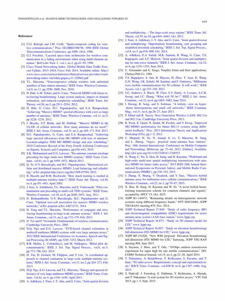
PAPADOPOULOS et al.: MASSIVE MIMO TECHNOLOGIES AND CHALLENGES TOWARDS 5G619
References
[1] G.G. Raleigh and J.M. Cioffi, “Spatio-temporal coding for wire-less communications,” Proc. GLOBECOM’96. 1996 IEEE GlobalTelecommunications Conference, pp.1809–1814, 1996.
[2] G.J. Foschini, “Layered space-time architecture for wireless com-munication in a fading environment when using multi-element an-tennas,” Bell Labs Tech. J., vol.1, no.2, pp.41–59, 1996.
[3] Cisco Visual Networking Index: Global Mobile Data Traffic Fore-cast Update, 2013–2018, Cisco, Feb. 2014. Available online: http://www.cisco.com/c/en/us/solutions/collateral/service-provider/visual-networking-index-vni/white paper c11-520862.pdf
[4] T.L. Marzetta, “Noncooperative cellular wireless with unlimitednumbers of base station antennas,” IEEE Trans. Wireless Commun.,vol.9, no.11, pp.3590–3600, Nov. 2010.
[5] H. Huh, A.M. Tulino, and G. Caire, “Network MIMO with linear ze-ro-forcing beamforming: Large system analysis, impact of channelestimation, and reduced-complexity scheduling,” IEEE Trans. Inf.Theory, vol.58, no.5, pp.2911–2934, 2012.
[6] H. Huh, G. Caire, H.C. Papadopoulos, and S.A. Ramprashad,“Achieving “Massive MIMO” spectral efficiency with a not-so-largenumber of antennas,” IEEE Trans. Wireless Commun., vol.11, no.9,pp.3226–3239, 2012.
[7] J. Hoydis, S.T. Brink, and M. Debbah, “Massive MIMO in theUL/DL of cellular networks: How many antennas do we need?,”IEEE J. Sel. Areas. Commun., vol.31, no.2, pp.160–171, Feb. 2013.
[8] H.C. Papadopoulos, G. Caire, and S.A. Ramprashad, “Achievinglarge spectral efficiencies from MU-MIMO with tens of antennas:Location-adaptive TDD MU-MIMO design and user scheduling,”2010 Conference Record of the Forty Fourth Asilomar Conferenceon Signals, Systems and Computers, pp.636–643, 2010.
[9] S.K. Mohammed and E.G. Larsson, “Per-antenna constant envelopeprecoding for large multi-user MIMO systems,” IEEE Trans. Com-mun., vol.61, no.3, pp.1059–1071, March 2013.
[10] Q. Ye, O.Y. Bursalioglu, and H.C. Papadopoulos, “Harmonized cel-lular and distributed massive MIMO: Load balancing and schedul-ing,” arXiv preprint http://arxiv.org/abs/1509.07594, 2015.
[11] B. Hassibi and B.M. Hochwald, “How much training is needed inmultiple-antenna wireless links?,” IEEE Trans. Inf. Theory, vol.49,no.4, pp.951–963, April 2003.
[12] J. Jose, A. Ashikhmin, T.L. Marzetta, and S. Vishwanath, “Pilot con-tamination and precoding in multi-cell TDD systems,” IEEE Trans.Wireless Commun., vol.10, no.8, pp.2640–2651, Aug. 2011.
[13] D. Bethanabhotla, O.Y. Bursalioglu, H.C. Papadopoulos and G.Caire, “Optimal user-cell association for massive MIMO wirelessnetworks,” arXiv preprint arXiv:1407.6731, 2014.
[14] H. Yang and T.L. Marzetta, “Performance of conjugate and zero-forcing beamforming in large-scale antenna systems,” IEEE J. Sel.Areas. Commun., vol.31, no.2, pp.172–179, Feb. 2013.
[15] D. Tse and P. Viswanath, Fundamentals of wireless communication,Cambridge University Press, 2005.
[16] H.Q. Ngo and E.G. Larsson, “EVD-based channel estimation inmulticell multiuser MIMO systems with very large antenna arrays,”2012 IEEE International Conference on Acoustics, Speech and Sig-nal Processing (ICASSP), pp.3249–3252, March 2012.
[17] R.R. Muller, L. Cottatellucci, and M. Vehkapera, “Blind pilot de-contamination,” IEEE J. Sel. Top. Signal Process., vol.8, no.5,pp.773–786, Oct. 2014.
[18] H. Yin, D. Gesbert, M. Filippou, and Y. Liu, “A coordinated ap-proach to channel estimation in large-scale multiple-antenna sys-tems,” IEEE J. Sel. Areas. Commun., vol.31, no.2, pp.264–273, Feb.2013.
[19] H.Q. Ngo, E.G. Larsson, and T.L. Marzetta, “Energy and spectral ef-ficiency of very large multiuser MIMO systems,” IEEE Trans. Com-mun., vol.61, no.4, pp.1436–1449, April 2013.
[20] A. Adhikary, J. Nam, J.-Y. Ahn, and G. Caire, “Joint spatial division
and multiplexing — The large-scale array regime,” IEEE Trans. Inf.Theory, vol.59, no.10, pp.6441–6463, Oct. 2013.
[21] J. Nam, A. Adhikary, J.-Y. Ahn, and G. Caire, “Joint spatial divisionand multiplexing: Opportunistic beamforming, user grouping andsimplified downlink scheduling,” IEEE J. Sel. Top. Signal Process.,vol.8, no.5, pp.876–890, Oct. 2014.
[22] A. Adhikary, E.A. Safadi, M.K. Samimi, R. Wang, G. Caire, T.S.Rappaport, and A.F. Molisch, “Joint spatial division and multiplex-ing for mm-wave channels,” IEEE J. Sel. Areas. Commun., vol.32,no.6, pp.1239–1255, June 2014.
[23] U. Grenander and G. Szego, Toeplitz forms and their applications,Chelsea Pub Co, 1984.
[24] T.S. Rappaport, S. Sun, R. Mayzus, H. Zhao, Y. Azar, K. Wang,G.N. Wong, J.K. Schulz, M. Samimi, and F. Gutierrez, “Millimeterwave mobile communications for 5G cellular: It will work!,” IEEEAccess, vol.1, pp.335–349, 2013.
[25] J.G. Andrews, S. Buzzi, W. Choi, S.V. Hanly, A. Lozano, A.C.K.Soong, and J.C. Zhang, “What will 5G be?,” IEEE J. Sel. Areas.Commun., vol.32, no.6, pp.1065–1082, June 2014.
[26] I. Hwang, B. Song, and S. Soliman, “A holistic view on hyper--dense heterogeneous and small cell networks,” IEEE Commun.Mag., vol.51, no.6, pp.20–27, June 2013.
[27] P. Eldad and R. Stacey, Next Generation Wireless LANS: 802.11nand 802.11ac, Cambridge University Press, 2013.
[28] R. Porat, E. Ojard, N. Jindal, M. Fischer, and V. Erceg, “ImprovedMU-MIMO performance for future 802.11 systems using differ-ential feedback,” Proc. 2013 Information Theory and ApplicationsWorkshop (ITA), pp.1–5, 2013.
[29] C. Shepard, H. Yu, N. Anand, E. Li, T. Marzetta, R. Yang,and L. Zhong, “Argos: practical many-antenna base stations,”Proc. 18th Annual International. Conference on Mobile Computerand Networking, Mobicom, pp. 53–64, 2012. [Online]. Available:http://doi.acm.org/10.1145/2348543.2348553
[30] X. Wang, C. Na, X. Hou, H. Jiang, and H. Kayama, “Wideband andhigh-order multi-user spatial multiplexing transmission with mas-sive MIMO for future radio access,” 2015 IEEE 26th Annual Inter-national Symposium on Personal, Indoor, and Mobile Radio Com-munications (PIMRC), pp.338–343, 2015.
[31] J. Zhang, X. Huang, V. Dyadyuk, and Y. Guo, “Massive hybridantenna array for millimeter-wave cellular communications,” IEEEWireless Commun., vol.22, no.1, pp.79–87, 2015.
[32] X. Hou, H. Jiang, H. Kayama and W. Xi, “A novel hybrid beam-forming transmission scheme for common channels and signals,”accepted by APCC’15, Oct. 2015.
[33] 3GPP R1-144972, “Remaining details on heterogeneous networkscenario using different frequency bands,” NTT DOCOMO, 3GPPTSG RAN1 meeting #79, Nov. 2014.
[34] 3GPP Technical Report 37.840: “Study of radio frequency (RF)and electromagnetic compatibility (EMC) requirements for activeantenna array system (AAS) base station,” www.3gpp.org.
[35] 3GPP Technical Report 36.873: “Study on 3D channel model forLTE,” www.3gpp.org.
[36] 3GPP Technical Report 36.897: “Study on elevation beamforming/full-dimension (FD) MIMO for LTE,” www.3gpp.org.
[37] 3GPP RP-151028, “New WID proposal: Elevation beamforming/full-dimension (FD) MIMO for LTE,” Samsung, 3GPP TSG RANmeeting #68, June 2015.
[38] S. Suyama, J. Shen, and Y. Oda, “10 Gbps outdoor transmissionexperiment for super high bit rate mobile communications,” DO-COMO Technical Journal, vol.15, no.4, pp.22–28, April 2014.
[39] T. Nakamura, A. Benjebbour, Y. Kishiyama, S. Suyama, and T.Imai, “5G radio access: Requirements, concept and experimental tri-als,” IEICE Trans. Commun., vol.E98-B, no.8, pp.1397–1406, Aug.2015.
[40] S. Parkvall, J. Furuskog, E. Dahlman, Y. Kishiyama, A. Harada,and T. Nakamura “A trial system for 5G wireless access,” VTC Fall2015, pp.1–5, Sept. 2015.
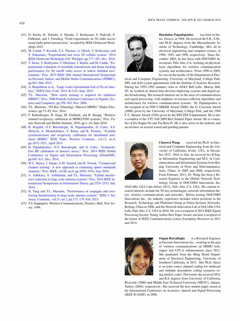
620IEICE TRANS. COMMUN., VOL.E99–B, NO.3 MARCH 2016
[41] D. Kurita, K. Tateishi, A. Harada, Y. Kishiyama, S. Parkvall, E.Dahlman, and J. Furuskog “Field experiments on 5G radio accessusing multi-point transmission,” accepted by IEEE Globecom Work-shops 2015.
[42] M. Cudak, T. Kovarik, T.A. Thomas, A. Ghosh, Y. Kishiyama, andT. Nakamura, “Experimental mm wave 5G cellular system,” 2014IEEE Globecom Workshops (GC Wkshps), pp.377–381, Dec. 2014.
[43] Y. Inoue, Y. Kishiyama, Y. Okumura, J. Kepler, and M. Cudak, “Ex-perimental evaluation of downlink transmission and beam trackingperformance for 5G mmW radio access in indoor shielded envi-ronment,” Proc. 2015 IEEE 26th Annual International Symposiumon Personal, Indoor, and Mobile Radio Communications (PIMRC),pp.862–866, 2015.
[44] A. Benjebbour et al., “Large scale experimental trial of 5G air inter-face,” IEICE Gen. Conf. 2015, B-5-63, Sept. 2015.
[45] T.L. Marzetta, “How much training is required for multiuserMIMO?,” Proc. 2006 Fortieth Asilomar Conference on Signals, Sys-tems and Computers, pp.359–363, Nov. 2006.
[46] T.L. Marzetta, “5G Key Tehnology: Massive MIMO,” Nikkei Elec-tronics, pp.73–82, Nov. 2014.
[47] F. Kaltenberger, H. Jiang, M. Guillaud, and R. Knopp, “Relativechannel reciprocity calibration in MIMO/TDD systems,” Proc. Fu-ture Network and Mobile Summit, 2010, pp.1–10, June 2010.
[48] R. Rogalin, O.Y. Bursalioglu, H. Papadopoulos, G. Caire, A.F.Molisch, A. Michaloliakos, V. Balan, and K. Psounis, “Scalablesynchronization and reciprocity calibration for distributed mul-tiuser MIMO,” IEEE Trans. Wireless Commun., vol.13, no.4,pp.1815–1831, April 2014.
[49] H. Papadopoulos, O.Y. Bursalioglu, and G. Caire, “Avalanche:Fast RF calibration of massive arrays,” Proc. 2014 IEEE GlobalConference on Signal and Information Processing (GlobalSIP),pp.607–611, Dec. 2014.
[50] W.U. Bajwa, J. Haupt, A.M. Sayeed, and R. Nowak, “Compressedchannel sensing: A new approach to estimating sparse multipathchannels,” Proc. IEEE, vol.98, no.6, pp.1058–1076, June 2010.
[51] A. Adhikary, A. Ashikhmin, and T.L. Marzetta, “Uplink interfer-ence reduction in large scale antenna systems,” Proc. 2014 IEEE In-ternational Symposium on Information Theory, pp.2529–2533, July2014.
[52] H. Yang and T.L. Marzetta, “Performance of conjugate and zero-forcing beamforming in large-scale antenna systems,” IEEE J. Sel.Areas. Commun., vol.31, no.2, pp.172–179, Feb. 2013.
[53] T.S. Rappaport, Wireless Communications, Prentice–Hall, New Jer-sey, 1996.
Haralabos Papadopoulos was born in Ser-res, Greece, in 1968. He received the S.B., S.M.,and Ph.D. degrees from the Massachusetts In-stitute of Technology, Cambridge, MA, all inelectrical engineering and computer science, in1990, 1993, and 1998, respectively. Since De-cember 2005, he has been with DOCOMO In-novations, Palo Alto, CA, working on physical-layer algorithms for wireless communicationsystems and architectures. From 1998 to 2005,he was on the faculty of the Department of Elec-
trical and Computer Engineering, University of Maryland, College Park,MD, and held a joint appointment with the Institute of Systems Research.During his 1993–1995 summer visits to AT&T Bell Labs, Murray Hill,NJ, he worked on shared time-division duplexing systems and digital au-dio broadcasting. His research interests are in the areas of communicationsand signal processing, with emphasis on resource-efficient algorithms andarchitectures for wireless communication systems. Dr. Papadopoulos isthe recipient of an NSF CAREER Award (2000), the G. Corcoran Award(2000) given by the University of Maryland, College Park, and the 1994F. C. Hennie Award (1994) given by the MIT EECS department. He is alsoa coauthor of the VTC Fall 2009 Best Student Paper Award. He is a mem-ber of Eta Kappa Nu and Tau Beta Pi. He is also active in the industry andan inventor on several issued and pending patents.
Chenwei Wang received his Ph.D. in Elec-trical and Computer Engineering from the Uni-versity of California, Irvine, USA, in Decem-ber 2012. Prior to that, he received his B.Eng.in Information Engineering and M.S. in Com-munications and Information Systems from Bei-jing University of Posts and Telecommunica-tions, China, in 2005 and 2008, respectively.From February 2013, Dr. Wang has been a Re-search Engineer in the Mobile Network Tech-nology Group of DOCOMO Innovations Inc.
(DoCoMo USA Labs before 2012), Palo Alto, CA, USA. His current re-search interests include the 5G key technologies, network information the-ory, wireless communications and networks. Before joining DOCOMOInnovations Inc., his industry experience includes intern positions in theResearch, Technology and Platforms Group at Nokia Siemens Networks,Beijing, China in 2008, and the Network Innovation Lab of DoCoMo USALabs, Palo Alto, CA, USA in 2010. He was a recipient of 2014 IEEE SignalProcessing Society Young Author Best Paper Award, and also a recipient ofthe honor of IEEE Communications Letters Exemplary Reviewer in 2011and 2014.
Ozgun Bursalioglu is a Research Engineerat Docomo Innovations Inc., working in the areaof wireless communications on MIMO tech-niques and LTE-A enhancements since 2012.She graduated from the Ming Hsieh Depart-ment of Electrical Engineering, University ofSouthern California, in 2011. Her Ph.D. thesisis on joint source channel coding for multicastand multiple description coding scenarios us-ing rateless codes. Previously she received M.S.and B.S. degrees from University of California,
Riverside (2006) and Middle East Technical University (METU), Ankara,Turkey (2004), respectively. She received the best student paper award atthe International Conference on Acoustics, Speech and Signal Processing(IEEE ICASSP), in 2006.
PAPADOPOULOS et al.: MASSIVE MIMO TECHNOLOGIES AND CHALLENGES TOWARDS 5G621
Xiaolin Hou received his B.S. and Ph.D. de-grees from Beijing Univ. of Posts and Telecom-munications (BUPT), Beijing, China, in 2000and 2005, respectively. He joined DOCOMOBeijing Labs (DBL) in 2005 and now he is a viceprinciple researcher and research manager inDBL. He has been actively contributing to bothacademic research and 3GPP standardization inthe field of mobile broadband communications.His current research interests focus on 5G keytechnologies, including dynamic time division
duplexing, massive multiple-input multiple-output, and millimeter-wavecommunications.
Yoshihisa Kishiyama received his B.E.,M.E., and Dr. Eng. degrees from Hokkaido Uni-versity, Japan in 1998, 2000, and 2010, re-spectively. Since he joined NTT DOCOMO,INC. in 2020, he has been involved in researchand standardization activities for 4G LTE/LTE-Advanced and 5G. He is currently a Senior Re-search Engineer of 5G Laboratory in NTT DO-COMO for 5G radio access network researchgroup. His current research interests include 5Gradio interface design and 5G experimental tri-
als. In 2012, he received the International Telecommunication Union As-sociation of Japan (ITU-AJ) Encouragement Award for his contributions toLTE international standardization.