Embed Size (px)
Citation preview
Namn:
Laborationen godkänd:
Computer Organization, Lab Assignment 2
Computer Organization 6 hp
I/O handling
Purpose
The purpose of this laboratory exercise is to demonstrate how to write programs that interact with the different I/O devices available on the board. In particular, we show how to use the eight seven-segment displays and the five pushbuttons. Furthermore, we shall demonstrate a method, i.e. polling, that enables handling of external events triggered by some of the input devices.
Seven-segment displays Seven-segment displays are composed of seven different LED segments and are used to display different patterns by lighting different segments. The common usage of seven-segment displays is to display decimal (or sometimes hexadecimal) digits by using the seven different LED segments that can be lit. One seven-segment display requires seven input signals, where each signal is responsible for one of the seven LED segments. Depending on the state of the signal, the corresponding LED segment is turned on or off. An illustration of a seven-segment display, along with its inputs (denoted with “a” to “g”), is depicted in Figure 1.
Figure 1. A seven-segment display
Computer Organization, Lab Assignment 2
2
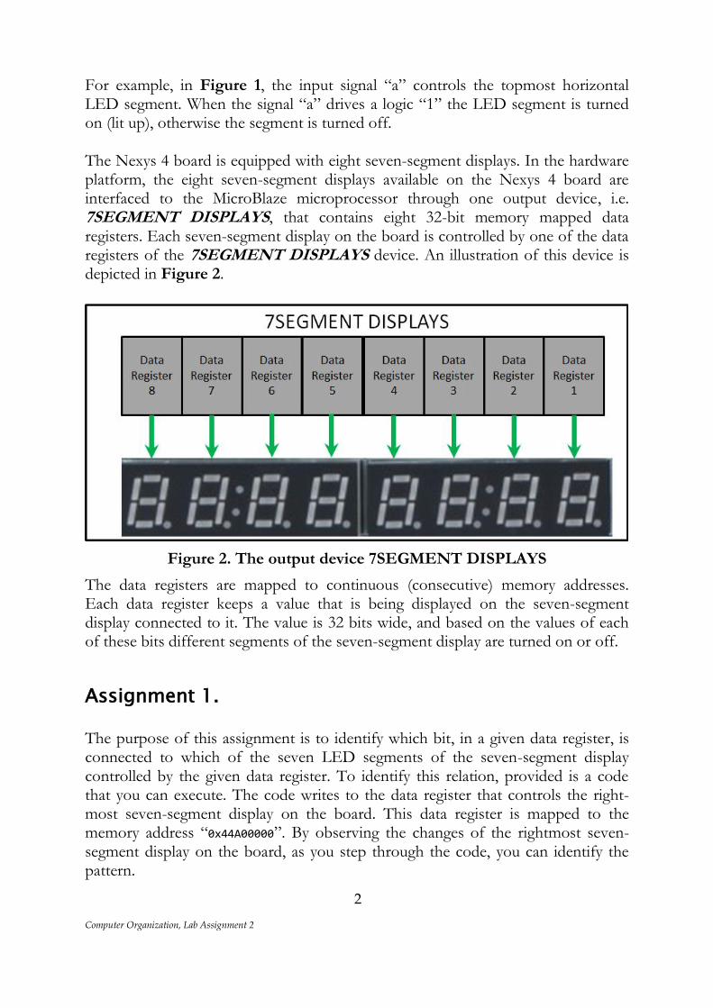
For example, in Figure 1, the input signal “a” controls the topmost horizontal LED segment. When the signal “a” drives a logic “1” the LED segment is turned on (lit up), otherwise the segment is turned off. The Nexys 4 board is equipped with eight seven-segment displays. In the hardware platform, the eight seven-segment displays available on the Nexys 4 board are interfaced to the MicroBlaze microprocessor through one output device, i.e. 7SEGMENT DISPLAYS, that contains eight 32-bit memory mapped data registers. Each seven-segment display on the board is controlled by one of the data registers of the 7SEGMENT DISPLAYS device. An illustration of this device is depicted in Figure 2.
Figure 2. The output device 7SEGMENT DISPLAYS
The data registers are mapped to continuous (consecutive) memory addresses. Each data register keeps a value that is being displayed on the seven-segment display connected to it. The value is 32 bits wide, and based on the values of each of these bits different segments of the seven-segment display are turned on or off.
Assignment 1. The purpose of this assignment is to identify which bit, in a given data register, is connected to which of the seven LED segments of the seven-segment display controlled by the given data register. To identify this relation, provided is a code that you can execute. The code writes to the data register that controls the right-most seven-segment display on the board. This data register is mapped to the memory address “0x44A00000”. By observing the changes of the rightmost seven-segment display on the board, as you step through the code, you can identify the pattern.
Computer Organization, Lab Assignment 2
3
In the current project, open the “main.c” source file, comment the code and put a note so that you can keep track to which assignment it belongs to. Repeat this step before each assignment. Copy the following code in the “main.c” source file.
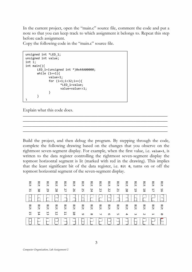
Explain what this code does. ________________________________________________________________________________________________________________________________________________________________________________________________________________________________________________________________ Build the project, and then debug the program. By stepping through the code, complete the following drawing based on the changes that you observe on the rightmost seven-segment display. For example, when the first value, i.e. value=1, is written to the data register controlling the rightmost seven-segment display the topmost horizontal segment is lit (marked with red in the drawing). This implies that the least significant bit of the data register, i.e. Bit 0, turns on or off the topmost horizontal segment of the seven-segment display.
Bit 31
Bit 30
Bit 29
Bit 28
Bit 27
Bit 26
Bit 25
Bit 24
Bit 23
Bit 22
Bit 21
Bit 20
Bit 19
Bit 18
Bit 17
Bit 16
Bit 15
Bit 14
Bit 13
Bit 12
Bit 11
Bit 10
Bit 9
Bit 8
Bit 7
Bit 6
Bit 5
Bit 4
Bit 3
Bit 2
Bit 1
Bit 0
unsigned int *LED_1; unsigned int value; int i; int main(){ LED_1=(unsigned int *)0x44A00000; while (1==1){ value=1; for (i=1;i<32;i++){ *LED_1=value; value=value<<1; } } }

Computer Organization, Lab Assignment 2
4
Assignment 2. The purpose of this assignment is to construct the patterns for each decimal digit. Based on the drawing in Assignment 1, construct a read-only (const) array of integers, where the elements of the array provide the codes for the corresponding digit, i.e. the element at index “i” in the array provides the pattern that displays the digit “i” on the seven-segment display. The template is provided bellow along with the code to display the digit “0”.
Assignment 3. The purpose of this assignment is to write a program that displays digits on the seven-segment displays. Since displaying a digit on a seven-segment display is a functionality that we might need to exploit in other programs as well, it is better to design a function that later can be invoked from the main program. Therefore, we design a function that takes two inputs: (1) an index to a particular seven-segment display, and (2) a digit. The advantage of having such a function is that we could easily call it from the main program whenever we need to output a value on any of the seven-segment displays program, without thinking of which code should be written into which register (the function will take care of it). To index a particular seven-segment display, we use the range 0-7, where index 0 refers to the rightmost seven-segment display and index 7 refers to the leftmost seven-segment display. For the designed system, the data registers controlling the eight seven-segment displays available on the board are mapped to consecutive memory addresses. Since the data registers are 32 bits wide (4 bytes), the difference between the addresses of two neighboring displays is equal to 4 (one byte is stored at each memory address). Utilizing the fact that the data registers controlling the displays are mapped to consecutive memory address, it is sufficient to know the base memory address (the address of the first data register) in order to obtain the memory address of the
const unsigned int display_codes[]= {0b0111111, // “index 0” 0b_______, // “index 1” 0b_______, // “index 2”
0b_______, // “index 3” 0b_______, // “index 4” 0b_______, // “index 5” 0b_______, // “index 6” 0b_______, // “index 7” 0b_______, // “index 8” 0b_______}; // “index 9”
Computer Organization, Lab Assignment 2
5
other data registers. By having the base address, we obtain the addresses of the other data registers by adding an offset to the base address. The base address can be defined in a header file. In the current project, create a new header file with the name “displays.h”. Copy and insert the following line in the recently created header file, between the “#define” and “#endif” directives. #define SEVEN_SEGMENT_DISPLAY_BASE 0x44A00000
The previous line defines the base address, which is as well the address of the data register controlling the rightmost seven-segment display. In C, a function needs be declared before it is used in the “main” function. A common practice is to provide the declarations of the functions in header files, while the definitions of the functions are provided in source files. Therefore, next we shall add the declaration of the function, which we are about to design, in the header file “displays.h”. Note that we shall use this header file to keep the declarations for all functions that deal with the seven-segment displays. In the header file “displays.h”, copy and insert the following line.
void displayDigitAtIndex(unsigned char index, unsigned char digit);
The previous line declares the function “displayDigitAtIndex”. This function does not provide any outputs, but has two inputs, i.e. index and digit, which are both of type unsigned char. So far, in the project we only had one single source file, i.e. “main.c”, where the “main” function was defined. However, one project may contain multiple source files, where in different source files definitions of different functions are provided. These different functions can be invoked from the “main” function. Note that in C, the “main” function dictates the beginning of the program. Following the common practice, we keep the definitions for all the functions declared in the header file “displays.h” in a separate source file, i.e. “displays.c”. Next, we provide the definition for the function “displayDigitAtIndex”. In the current project, create a new source file with the name “displays.c”, and then copy the following code:

Computer Organization, Lab Assignment 2
6
In the code that you copied, replace the commented section with the completed definition of the array “display_codes”. The completed definition is the result of Assignment 2. Study the code. Explain what the code does. ________________________________________________________________________________________________________________________________________________________________________________________________ ________________________________________________________________ To verify that the function “displayDigitAtIndex” is working properly, we write a new main program. The main program invokes the “displayDigitAtIndex” function and its purpose is to display the digits from 0 to 9 starting from the rightmost display in a round robin fashion. As there are only eight displays and ten digits are to be displayed, the rightmost displays shall be overwritten, i.e. the digit 8 will be displayed on the display with index 0, and the digit 9 will be displayed on the display with index 1. Open the “main.c” source file, comment the code and then copy and insert the following code.
Build the project and debug the code. Step through the code and verify that the correct digits are displayed on the different displays. Note that in case of incorrect representation of the digits, you will need to update the definition of the array “display_codes”.
#include "displays.h"
unsigned char i;
int main(){
while (1==1){
for (i=0;i<10;i++)
displayDigitAtIndex(i%8,i);
}
}
#include "displays.h" /* * COMMENT: * insert the completed definition of the array “display_codes” (Assignment 2) */ void displayDigitAtIndex(unsigned char index, unsigned char digit){ if ((index<8)&&(digit<10)) *((unsigned int *) (SEVEN_SEGMENT_DISPLAY_BASE +index*4))=display_codes[digit]; }

Computer Organization, Lab Assignment 2
7
Assignment 4. The purpose of this assignment is to design a function that displays an integer number on the displays. The number is displayed such that its least significant digit is visible on the rightmost seven-segment display. However, an integer number may have more than 8 digits (more than the available number of displays). Therefore, we shall also design an auxiliary function that counts the number of digits in a given integer number. The first step is to provide the declarations for these two functions. Copy the following lines in the “displays.h” file.
unsigned int numberOfDigits(unsigned int x); void displayNumber(unsigned int x);
The previous two lines declare the functions “numberOfDigits” and “displayNumber”. Both functions take a single input argument of type unsigned int. The function “displayNumber” does not provide any outputs, while the function “numberOfDigits” returns an output of type unsigned int. The next step is to provide the definitions for the previously declared functions. The definitions are to be written in the “displays.c” source file. Copy the following code in the “displays.c” file.
Study the codes of the two functions. Explain what each of the functions does. ________________________________________________________________________________________________________________________________ ________________________________________________________________
unsigned int numberOfDigits(unsigned int x){
unsigned int count=1;
while (x/10>0){
count++;
x=x/10;
}
return count;
}
void displayNumber(unsigned int x){
unsigned int index=0;
if (numberOfDigits(x)<9)
do {
displayDigitAtIndex(index,x%10);
index++;
x=x/10;
} while (x>0);
}

Computer Organization, Lab Assignment 2
8
What is going to be displayed on the displays if the function “displayNumber” is invoked with an integer number that has at least 9 digits?____________________ Modify the “main” function such that you can verify the correctness of these two functions. The new program should display few different numbers on the seven-segment displays. Ensure that the numbers that are displayed don’t have the same number of digits. Open the “main.c” source file, comment its contents and write the modified code following the template provided below.
Build the project and debug the code. Step through the code and observe the
changes. Use the Step Over button (F6) when you debug the program.
What happens when displaying a number that has less digits than a number that has been previously displayed? ________________________________ ___________________________________________________________
Assignment 5. To ensure that each number is correctly displayed, it is important to reset the displays before displaying a new number. Design a function that resets a given display based on its index. Name this function “resetDisplayAtIndex”. This function should have one input parameter, i.e. the index of the display that is to be reset. Add the declaration of the function in the “displays.h” header file, and define the function in the “displays.c” source file (for reference, see the previous examples).
#include "displays.h"
int main(){
while (1==1){
/*
* COMMENT:
* display numbers here
*/
}
}

Computer Organization, Lab Assignment 2
9
Assignment 6. Using the function “resetDisplayAtIndex”, create a function that resets all displays. Name this function “resetDisplays”. This function should not have any input parameters. Add the declaration of the function in the “displays.h” header file, and define the function in the “displays.c” source file (for reference, see the previous examples).
Assignment 7. Write a main program that verifies that the functions you have designed in Assignment 5 and 6 work properly. Don’t forget to comment the contents of the “main.c” source file before you apply the changes.
Assignment 8. Design a function with the name “displayNumberAtIndex” that takes two input arguments, an index and a number, to display a number at a given index position. Write a main program so that you can verify that the function works properly. Don’t forget to comment the contents of the “main.c” source file before you apply the changes.

Computer Organization, Lab Assignment 2
10
Pushbuttons A pushbutton produces one output signal, i.e. a logic ‘0’ or a logic ‘1’, based on whether the button is pressed or released. A pushbutton is illustrated in Figure. 3.
Figure. 3 A pushbutton
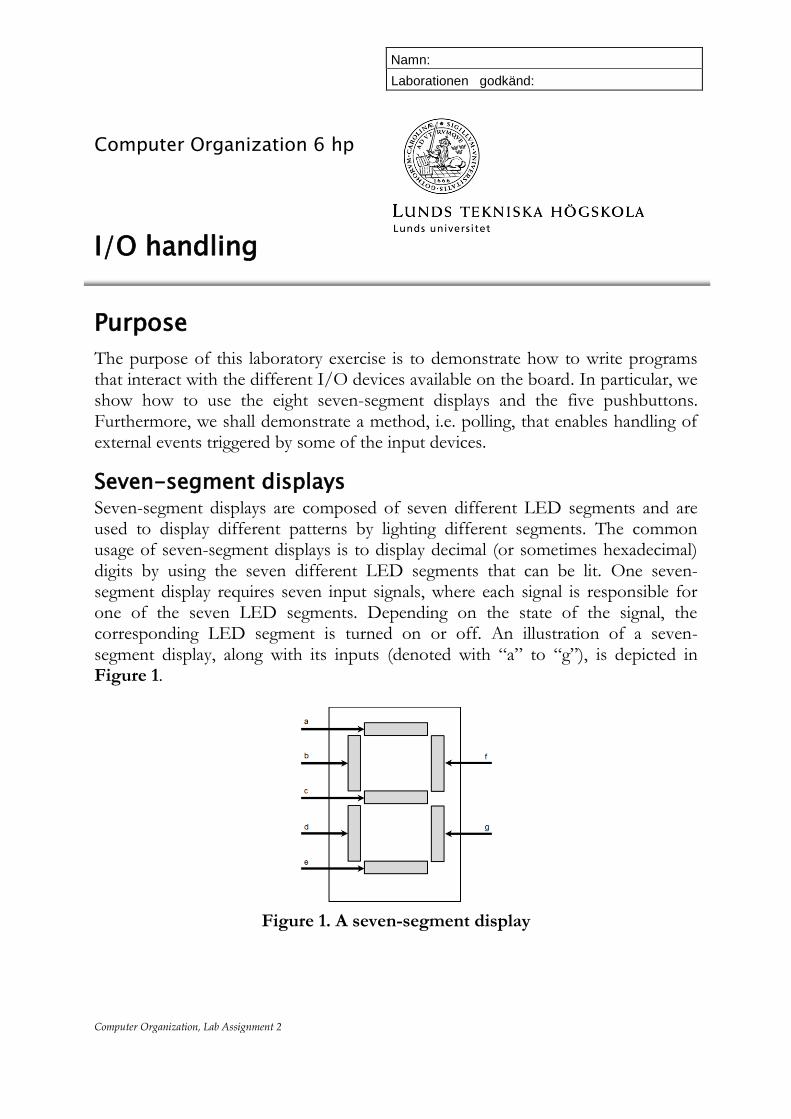
Five pushbuttons are available on the Nexys 4 board. In the hardware platform, these five pushbuttons are interfaced to the MicroBlaze microprocessor through one I/O device, i.e. PUSH BUTTONS. The PUSH BUTTONS device has one control and one data register. Both these registers are 32-bits wide and are mapped to known memory addresses. The control register is used to control the data flow direction for each of the bits in the data register. The outputs of the pushbuttons available on the Nexys 4 board are connected to the data register of the PUSH BUTTONS device, as illustrated in Figure 4.
Figure 4. PUSH BUTTONS I/O device

Computer Organization, Lab Assignment 2
11
Assignment 9. The purpose of this assignment is to identify to which particular bits in the data register of the PUSH BUTTONS device are the five pushbuttons, available on the Nexys 4 board, connected. For that purpose, provided is a code that you can run on the hardware platform, and by monitoring the changes you can identify the relation. As mentioned earlier, the PUSH BUTTONS device has one control and one data registers, each 32-bit wide, that are mapped to known memory addresses. For ease of reference, we define pointers which point to the memory addresses of the control and the data registers. These definitions are to be stored in a header file. Create a new header file with the name “buttons.h”, and add the following definitions: #define BUTTONS_DATA (unsigned int *) 0x40000000 #define BUTTONS_CONTROL (unsigned int *) 0x40000004
The PUSH BUTTONS device has to be configured as an input device, i.e. the data register should capture signals coming from the pushbuttons. This is done by writing “1s” in the control register of the device. The data register of this device keeps the current state of each of the buttons. Whenever a button is pressed, the particular bit of the data register to which the button is mapped to is set to 1, otherwise the bit is set to 0. Since there are five buttons, only five bits of the 32 bit long register are affected by the state of the buttons. To identify which bits are affected by each of the buttons, one can write a simple program that reads the data register of the PUSH BUTTONS and stores this data in a local variable. Open the “main.c” source file, comment its contents and type the following code:
The provided code, first configures the PUSH BUTTONS device as an input device by writing all ‘1’s in its control register, which is mapped to memory address “0x40000004”. Next, the program continuously reads the data register of the PUSH BUTTONS device, mapped at memory address “0x40000000”, and stores this information in the local variable “state”.
#include "buttons.h" unsigned int state; int main(){ *BUTTONS_CONTROL=0xFFFFFFFF;
while (1==1){ state=*BUTTONS_DATA;
} }

Computer Organization, Lab Assignment 2
12
Build the project and debug the program. Open the “Expression” view in the debug environment, and check the contents of the variable “state”. What is the value of the variable “state” when each of the buttons is pressed? Write the values in binary format. Hint: Make sure that a pushbutton is pressed when the debugger reads the data register. UP ______________________________ DOWN ______________________________ RIGHT ______________________________ LEFT ______________________________ MIDDLE ______________________________
Assignment 10. As you observed from Assignment 9, pressing a particular pushbutton writes a logic ‘1’ at a specific bit position in the data register of the PUSH BUTTONS device. By reading the data register of this device, a program can identify which particular button has been pressed. Instead of memorizing the different binary patterns for each of the pushbuttons, a more convenient way is to define labels. The purpose of having these labels is to refer to them in the code instead of writing the binary pattern. These labels can be stored in a header file. Open the “buttons.h” header file, and insert the following lines.
#define UP 0b?????
#define DOWN 0b?????
#define MIDDLE 0b?????
#define LEFT 0b?????
#define RIGHT 0b?????
Complete the definitions, such that the binary patterns “0b?????” correspond to the correct patterns for each of the buttons, which you already have identified in Assignment 9.

Computer Organization, Lab Assignment 2
13
Polling So far, we showed how to interact with input and output devices. However, in many cases the communication with these devices is strictly defined and is usually not as straight forward as just reading or writing to data registers. Polling refers to periodically sampling the status of an external (input or output) device to determine the need to service the device. Only when a device is ready, a program (the processor or other programmable controller) can exchange data with the device. In these labs, the I/O devices that are used are not very complex. Still, for illustrative purposes we show the basic principle of polling. The polling principle can be used to sample the state of the pushbuttons. The pushbuttons can provide trigger events whenever they are pressed or released. To capture these trigger events one needs to continuously sample the state of the pushbuttons.
Assignment 11. In this assignment, we demonstrate the polling principle for the five pushbuttons available on the Nexys 4 board. If none of the buttons is pressed, then all bits in the data register of the PUSH BUTTONS device are set to 0. This can be used as an indication that the device does not have any valuable input, and thus the processor should wait until the device has some data available. However, when a button is pressed, depending on which button has been pressed different actions can be taken. The goal of the assignment is to write a program that implements the following algorithm:
1) When the program starts, a zero is displayed on the seven-segment displays. 2) If no buttons are pressed, no changes occur on the displays. 3) When the “up” button is pressed, the displayed value is incremented by one 4) When the “down” button is pressed, the value displayed is decremented by
one 5) Repeat steps 2-5
The following code is one implementation of the algorithm described earlier:

Computer Organization, Lab Assignment 2
14
Open the “main.c” source file, comment its contents, and copy and insert the provided code. Build the project and run the program, by clicking the “Resume” button. Push the “up” and the “down” buttons and observe the changes on the display. Does the provided code work well in practice?____________________________ Why does the displayed value change much more rapidly than expected? Hint: The MicroBlaze processor operates at 100MHz frequency ________________________________________________________________________________________________________________________________________________________________________________________________ What happens when you press and hold the “down” button?_________________ What is the explanation for this phenomena?______________________________ ________________________________________________________________________________________________________________________________ Would similar thing happen if you press and hold the “up” button?____________ ________________________________________________________________________________________________________________________________________________________________________________________________ How can you solve the two problems above? _____________________________ ________________________________________________________________________________________________________________________________
#include "buttons.h" #include "displays.h" unsigned int counter; int main(){ *BUTTONS_CONTROL=0xFFFFFFFF;
counter=0; while (1==1){ resetDisplays(); displayNumber(counter); while (*BUTTONS_DATA==0); // keep reading the data register
if (*BUTTONS_DATA==UP) counter++; if (*BUTTONS_DATA==DOWN) counter--;
} }

Computer Organization, Lab Assignment 2
15
Assignment 12. The purpose of this assignment is to show how to avoid the problems you have encountered in Assignment 11. To avoid the problems, we modify the algorithm described in Assignment 11 by adding some more details. The modified algorithm is as follows:
1. When the program starts, a zero is displayed on the seven-segment displays. 2. If no buttons are pressed, no changes occur on the displays. 3. If a button is pressed, the data register of the input device is read and it is
stored in a local variable. 4. Depending on the value of this variable, the displayed value is incremented if
the “up” button is pressed or decremented if the “down” button is pressed. 5. Wait until a new button is pressed, or until the current button is released. 6. Repeat steps 2-6.
The following code implements the algorithm above.
Open the “main.c” source file, comment its contents and copy and insert the provided code. Build the project and run the program. Does the provided code work well in practice?____________________________ What do you observe?_______________________________________________
#include "buttons.h" #include "displays.h" unsigned int counter; unsigned int buttons_state; int main(){ *BUTTONS_CONTROL=0xFFFFFFFF;
counter=0; while (1==1){ resetDisplays(); displayNumber(counter); while (*BUTTONS_DATA==0); // keep reading the data register buttons_state=*BUTTONS_DATA;
if (buttons_state==UP) counter++; if (buttons_state==DOWN) counter--; while (*BUTTONS_DATA==buttons_state);
} }

Computer Organization, Lab Assignment 2
16
Assignment 13. As you observe, after implementing the algorithm in Assignment 12, in many cases when you press and hold a button, the displayed value is incremented or decremented only by one. However, sometimes it happens that when you press a button the value is incremented/decremented by more than one. The reason for this is a problem known as “bouncing”. Bouncing is the tendency of any two metal contacts in an electronic device to generate multiple signals as the contacts close or open. Thus, when a button is pressed, the value of the bit to which it is connected oscillates between zero and one, before it finally stabilizes to one (when the bit is set to one, it means that the particular button is pressed). Since in the while loops, we read the data register with a very high frequency, this makes it possible to capture the non-intended transitions of the bit rendering the event of pressing the button once as multiple events. To avoid the problem of bouncing, we could add some delays between two consecutive read operations on the data register. A typical way to add some delay is by adding a for-loop that does not do anything useful. The modified code that takes the delay into account is provided below.
Open the “main.c” source file, comment its contents and copy and insert the provided code. Build the project and run the program. Check whether this implementation fixes the problem of bouncing.
#include "buttons.h" #include "displays.h" unsigned int counter; unsigned int buttons_state; unsigned int i; int main(){ *BUTTONS_CONTROL=0xFFFFFFFF;
counter=0; while (1==1){ resetDisplays(); displayNumber(counter); while (*BUTTONS_DATA==0);
for (i=0;i<20000;i++); buttons_state=*BUTTONS_DATA;
if (buttons_state==UP) counter++; if (buttons_state==DOWN) counter--; while (*BUTTONS_DATA==buttons_state); for (i=0;i<20000;i++);
} }
Computer Organization, Lab Assignment 2
17
Assignment 14. Use the code from Assignment 13. Build the project and run the program. Press and hold the right pushbutton, and then press the up or the down button. Release the buttons. What happens with the counter?________________________ Press and hold the left pushbutton, and then press the up or the down button. Release the buttons. What happens with the counter?_______________________ Press and hold the middle pushbutton, and then press the up or the down button. Release the buttons. What happens with the counter?_______________________ Suggest a solution, such that the counter will be modified as long as either the up or the down button is pressed, irrespective of the state of the other pushbuttons. Modify the code and verify that it works as expected. Don’t forget to comment the contents of the “main.c” source file before you apply the changes.
Assignment 15. The code from the previous assignment does not take into account the range of values that could be presented on the displays. Modify the code such that the variable “counter” can only take values which are in the range that can be displayed. Apply the changes, and verify that the program works as expected. Don’t forget to comment the contents of the “main.c” source file before you apply the changes.
Assignment 16. In Assignments 11-15, the changes on the displays are only visible once any of the pushbuttons is released. Modify the code such that the changes are visible once a button is pressed. Apply the changes, build the project, and run the program so that you can verify that it works as expected. Don’t forget to comment the contents of the “main.c” source file before you apply the changes.
Assignment 17. Similar to the previous assignments, write a program that implements the following algorithm:
1. When the program starts, a zero is displayed on the seven-segment displays. 2. If no buttons are pressed, no changes occur on the displays. 3. If the “up” button is pressed, the displayed value is incremented by one. 4. If the “down” button is pressed, the value is decremented by one. 5. If the “middle” button is pressed, zero is displayed. 6. If the “right” button is pressed, the displayed value is shifted one position to
the right. 7. If the “left” button is pressed, the displayed number is shifted one position
to the left. 8. Repeat steps 2-8.