Embed Size (px)
Citation preview

ioLogik R2110 Series User’s Manual RS-485 Remote I/O Server with 12 DI, 8 DO
First Edition, July 2006
www.moxa.com/product
MOXA Technologies Co., Ltd.Tel: +886-2-8919-1230 Fax: +886-2-8919-1231 Web: www.moxa.com MOXA Technical Support Worldwide: [email protected]
ioLogik R2110 User’s Manual The software described in this manual is furnished under a license agreement, and may be used only in
accordance with the terms of that agreement.
Copyright Notice
Copyright © 2006 MOXA Technologies Co., Ltd. All rights reserved.
Reproduction without permission is prohibited.
Trademarks
MOXA is a registered trademark of the MOXA Group. All other trademarks or registered marks in this manual belong to their respective manufacturers.
Disclaimer
Information in this document is subject to change without notice, and does not represent a commitment on the part of MOXA.
MOXA provides this document “as is,” without warranty of any kind, either expressed or implied, including, but not limited to, its particular purpose. MOXA reserves the right to make improvements, and/or changes to this manual, or to the products, and/or the programs described in this manual, at any time.
Information provided in this manual is intended to be accurate, and reliable. However, MOXA assumes no responsibility for its use, or for any infringements on the rights of third parties that may result from its use.
This manual might include unintentional technical or typographical errors. Changes are made periodically to the information herein to correct such errors, and these changes are incorporated into new editions of the manual.

Table of Contents Chapter 1 Introduction ...............................................................................................1-1
Overview .............................................................................................................................. 1-2 Features of the ioLogik R2110 RS-485 Remote I/O Server ................................................. 1-2 Package Checklist................................................................................................................. 1-3 Product Specifications .......................................................................................................... 1-3
All ioLogik R2000 Series Remote I/O Servers............................................................. 1-3 Specific to the ioLogik R2110...................................................................................... 1-4
Pin Assignment..................................................................................................................... 1-5 Terminal Blocks ........................................................................................................... 1-5 Setting the RS-485 Communication Speed................................................................... 1-5
Chapter 2 Hardware Installation ................................................................................2-1 Connecting the Hardware ..................................................................................................... 2-2
Connecting the Power................................................................................................... 2-2 Grounding the ioLogik R2110...................................................................................... 2-2 Connecting to I/O Device Servers ................................................................................ 2-2 LED Indicators ............................................................................................................. 2-3
Factory Default Settings ....................................................................................................... 2-3 ioAdmin................................................................................................................................ 2-3 LCD Display Module ........................................................................................................... 2-4
Chapter 3 Configuring the ioLogik R2110 with ioAdmin.........................................3-1 Overview .............................................................................................................................. 3-2 Installing ioAdmin................................................................................................................ 3-2 Searching for the ioLogik R2110.......................................................................................... 3-3 Monitoring I/O Status........................................................................................................... 3-5 On-line Wiring Guide ........................................................................................................... 3-6 Modbus/RTU ........................................................................................................................ 3-7 Server Information................................................................................................................ 3-8 Logging In ............................................................................................................................ 3-8 Configuring Digital Input/Output Channels ......................................................................... 3-8
Testing DI/O Channels ................................................................................................. 3-9 Configuring Digital Input Channels ........................................................................... 3-10 Configuring Digital Output Channels......................................................................... 3-12 About Power On Settings ........................................................................................... 3-13 About Safe Status Settings.......................................................................................... 3-13
Host Connection Watchdog ................................................................................................ 3-14 Restarting the System ......................................................................................................... 3-15 Restoring Default Settings.................................................................................................. 3-15 Exporting ioLogik R2110 Settings ..................................................................................... 3-16 Password Protection ........................................................................................................... 3-17 Firmware Update ................................................................................................................ 3-17
Appendix A Modbus/RTU Address Mappings ............................................................ A-1 ioLogik R2110 Modbus Mapping........................................................................................ A-1
0xxxx Read/Write Coils (Support Functions 1, 5, 15)................................................. A-1 1xxxx Read-Only Coils (Support Function 2) ............................................................. A-5 3xxxx Read Only Registers (Support Function 4) ....................................................... A-5 4xxxx Read/Write Registers (Support Functions 3, 6, 16) .......................................... A-6

Function 8.................................................................................................................... A-8
Appendix B Factory Default Settings .......................................................................... B-1
Appendix C Port Pinout Diagrams............................................................................... C-1 Serial Port Pinouts ................................................................................................................C-1
Appendix D Service Information.................................................................................. D-1 MOXA Internet Services ..................................................................................................... D-2 Problem Report Form .......................................................................................................... D-3 Product Return Procedure.................................................................................................... D-4

11 Chapter 1 Introduction
The ioLogik R2110 is an Easy View, stand-alone, remote digital I/O server that can be used to connect sensors and on/off switches over an RS-485 connection for use in automation applications.
The following topics are covered in this chapter:
Overview Features of the ioLogik R2110 RS-485 Remote I/O Server Package Checklist Product Specifications
All ioLogik R2000 Series Remote I/O Servers Specific to the ioLogik R2110
Pin Assignment Terminal Blocks Setting the RS-485 Communication Speed

ioLogik R2110 Series User’s Manual Introduction
1-2
Overview Without LCD Display Module With LCD Display Module
The ioLogik R2110 is part of the R2000 series of ioLogik Remote I/O servers, which are designed to link sensors, transmitters, transducers, and valves to an RS-485 network. The ioLogik R2110 is differentiated from other R2000 series models by its digital I/O and its Easy View function. As an Easy View device, the ioLogik R2110 supports an optional hot-pluggable LCD display module to view and configure device settings.
The ioLogik R2110 can be connected to ioLogik E2000 series servers to allow each of the field I/O points to be accessed from within a single IP environment. One ioLogik E2000 series server can connect up to 31 ioLogik R2000 series servers.
Features of the ioLogik R2110 RS-485 Remote I/O Server 12 DI (digital input) channels, 8 DO (digital output) channels Multi-functional I/O that supports DI/Event Counter and DO/Pulse Output Connects to RS-485 network using Modbus protocol, allowing communication with standard
SCADA software (e.g. Wonderware InTouch or GE Intellution iFix32) Supports optional hot-pluggable LCD module for status display and configuration Supports remote firmware updates via RS-485 Monitoring and configuration with ioAdmin, a graphic user interface Hardware detection through RS-485 network with ioAdmin Modbus register settings viewable with ioAdmin Status of each I/O accessible over RS-485 network running the MXIO DLL library (coming
soon) Built-in watchdog timer with configurable safe DI/O channel settings Configurable power-on DI/O channel settings Uses one IP address per server
NOTE: ioAdmin is a utility designed by MOXA for configuration and monitroing of the ioLogik R2110. See Chapter 3 for detailed information about ioAdmin.

ioLogik R2110 Series User’s Manual Introduction
1-3
Package Checklist The ioLogik R2110 is shipped with the following items:
Standard Accessories ioLogik R2110 RS-485 I/O Server × 1 Software CD with documentation × 1
Optional Accessories LDP1602 ioLogik LCD display module (16 × 2 text screen and 5 push-buttons)
NOTE: Notify your sales representative if any of these items are missing or damaged.
Product Specifications ioLogik R2110
12 isolated DI channels, 8 isolated DO channels, Modbus/RTU
All ioLogik R2000 Series Remote I/O Servers The following specifications apply to all models in the R2000 series of ioLogik Remote I/O servers:
Serial 2-wire RS-485 for module cascading, terminal block (3.81 mm), supports data+, data- Baudrate up to 115.2 kbps Built-in ADDC™ 15 KV ESD for all serial signals
Protocols Modbus/RTU
Windows Utilities ioAdmin for remote configuration and monitoring
Operating Modes for Host Control Modbus/RTU DLL for VB, BCB, VC++ with comprehensive examples (coming soon)
Built-in Watchdog Timer Configurable host communication watchdog timer to reset device to safe status
Configuration Automatic detection over RS-485 with ioAdmin Remote firmware upgrade Export configuration settings to a file
Power Input 12 to 48 VDC, accepts 24 VDC industrial power supply, power consumption 195 mA @ 24 VDC Reverse polarity protection
Environmental Operating Temp: -10 to 60°C @ 95% RH

ioLogik R2110 Series User’s Manual Introduction
1-4
Ground Connection DIN-rail, and panel mount holes equipped ground connection
Terminal Block Removable terminal block (3.81 mm) (DI/O) Signal indication LEDs for each channel (DI/O) Regulatory approval
Shock, free fall, vibration CE Class A, Level 3, Criteria B FCC Part 15, CISPR (EN55022) class A UL 508 (pending)
Specific to the ioLogik R2110 The following specifications differentiate the ioLogik R2110 from other models in the R2000 series of ioLogik Remote I/O servers
I/O Type 12 DI, 8 DO
Digital Input Dry contact Logic 0: close to GND Logic 1: open Wet contact Logic 0: 0 to 3 VDC Logic 1: 10 to 30 VDC Low speed counter for limit switch with filtering (in 10 ms intervals) Excess voltage protection (withstands voltage up to +36 VDC) Source Optical isolation 3K VDC Pulse wave form settings in 10 ms Excess voltage protection (withstands voltage up to +36 VDC)
Digital Output Sink, 24 VDC, 200 mA Optical isolation 3K VDC Protection over temperature shutdown: Min, 170°C Over voltage protection: 36 VDC Over current limit: typ. 750 mA
LCD Display Module for Easy View Devices (Optional Accessory) Text 16 × 2 LCM with backlight Button × 5 (up, down, right, left, center) Hot pluggable to any ioLogik Easy View device Unit ID, baudrate display, DI/O status display

ioLogik R2110 Series User’s Manual Introduction
1-5
Pin Assignment Terminal Blocks
TB3
TB2TB1
UNIT IDx10 x1
R2110 RS-485
TB1 Signals TB2 Signals1 V+ (12 to 48 VDC) 1 Data+ 2 V- 2 Data- 3 FG 3 SG
TB3 1 2 3 4 5 6 7 8
Signals DI.COM DI 0 DI 1 DI 2 DI 3 DI 4 DI 5 DI 6
TB3 9 10 11 12 13 14 15 16 Signals DI 7 DI 8 DI 9 DI 10 DI 11 DI.GND DO.PWR DO 0
TB3 17 18 19 20 21 22 23 24
Signals DO 1 DO 2 DO 3 DO 4 DO 5 DO 6 DO 7 DO.GND
Setting the RS-485 Communication Speed The RS-485 port on the ioLogik R2110 is used to communicate with other RS-485 devices or to link to another RS-485 I/O server. The RS-485 port can run Modbus/RTU or I/O command sets.
The baudrate is set by a physical dial on the back of the ioLogik R2110. The default settings are baudrate = 115200, parity check = N, data bits = 8, and stop bit = 1.
Setting the Baudrate
Baudrate for RS-485 (parameters are N, 8, 1)
Dial setting and corresponding baudrate: 0:115200 1:57600 2:38400 3:19200 4:9600 5:4800 6:2400 7:1200

22 Chapter 2 Hardware Installation
In this chapter, we describe the hardware installation procedure for the ioLogik R2110 remote I/O server.
The following topics are covered in this chapter.
Connecting the Hardware Connecting the Power Grounding the ioLogik R2110 Connecting to I/O Device Servers LED Indicators
Factory Default Settings ioAdmin LCD Display Module

ioLogik R2110 Series User’s Manual Hardware Installation
2-2
Connecting the Hardware Connecting the Power
Connect the 12 to 48 VDC power line with the ioLogik R2110’s terminal block. If the power is properly supplied, the power LED will glow a solid red color until the system is ready
Grounding the ioLogik R2110 The ioLogik R2110 is equipped with two protection ground points. One is on the wall mount hole and the other is on the DIN-rail mounting rail.
Connecting to I/O Device Servers 1. DI dry contact
2. DI wet contact (source type)

ioLogik R2110 Series User’s Manual Hardware Installation
2-3
3. DO sink type
* DO PWR is for powering up the field power LED
LED Indicators LED Description
System LEDs
PWR Red The power is on.
Red There is a system error.
Green The ioLogik is functioning normally.
Off The power is off or a power error condition exists. Ready
Flashing Red/Green The ioLogik is in safe status.
Serial Blinking The serial port is receiving and transmitting data.
DI/O LEDs
DI ×12 pins DO × 8 pins Field PWR
In 0, 1, 2, 3, 4, 5, 6, 7, 8, 9, 10, 11 Out 0, 1, 2, 3, 4, 5, 6, 7 Field power
Factory Default Settings The ioLogik R2110 is configured with the following default settings:
Default RS-485 Unit ID: 1 Default communication baudrate: 115200 bps
ioAdmin ioAdmin is a Windows utility used to configure the ioLogik R2110, export your settings, and monitor the ioLogik R2110 remotely.
ioLogik R2110 Series User’s Manual Hardware Installation
2-4
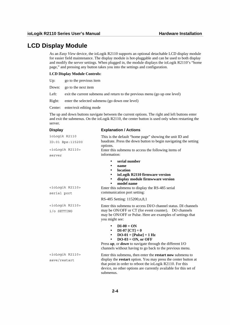
LCD Display Module As an Easy View device, the ioLogik R2110 supports an optional detachable LCD display module for easier field maintenance. The display module is hot-pluggable and can be used to both display and modify the server settings. When plugged in, the module displays the ioLogik R2110’s “home page,” and pressing any button takes you into the settings and configuration.
LCD Display Module Controls:
Up: go to the previous item
Down: go to the next item
Left: exit the current submenu and return to the previous menu (go up one level)
Right: enter the selected submenu (go down one level)
Center: enter/exit editing mode
The up and down buttons navigate between the current options. The right and left buttons enter and exit the submenus. On the ioLogik R2110, the center button is used only when restarting the server.
Display Explanation / Actions ioLogik R2110
ID:01 Bps:115200
This is the default “home page” showing the unit ID and baudrate. Press the down button to begin navigating the setting options.
<ioLogik R2110>
server
Enter this submenu to access the following items of information:
serial number name location ioLogik R2110 firmware version display module firmwware version model name
<ioLogik R2110>
serial port
Enter this submenu to display the RS-485 serial communication port setting:
RS-485 Setting: 115200,n,8,1 <ioLogik R2110>
i/o SETTING
Enter this submenu to access DI/O channel status. DI channels may be ON/OFF or CT (for event counter). DO channels may be ON/OFF or Pulse. Here are examples of settings that you might see:
DI-00 = ON DI-07 [CT] = 0 DO-01 = [Pulse] = 1 Hz DO-03 = ON, or OFF
Press up, or down to navigate through the different I/O channels without having to go back to the previous menu.
<ioLogik R2110>
save/restart
Enter this submenu, then enter the restart now submenu to display the restart option. You may press the center button at that point in order to reboot the ioLogik R2110. For this device, no other options are currently available for this set of submenus.

33 Chapter 3 Configuring the ioLogik R2110
with ioAdmin
This chapter covers the following topics explains how to configure the I/O channels.
Overview Installing ioAdmin Searching for the ioLogik R2110 Monitoring I/O Status On-line Wiring Guide Modbus/RTU Server Information Logging In Configuring Digital Input/Output Channels
Testing DI/O Channels Configuring Digital Input Channels Configuring Digital Output Channels About Power On Settings About Safe Status Settings
Host Connection Watchdog Restarting the System Restoring Default Settings Exporting ioLogik R2110 Settings Password Protection Firmware Update

ioLogik R2110 Series User’s Manual Configuring with ioAdmin
3-2
Overview ioAdmin is a monitoring and configuration utility designed for use with ioLogik R2000 series I/O servers. It supports Windows 2000 and Windows XP and consists of the following software.
ioAdmin ioLogik R2110 Wiring Guide MXIO DLL library (coming soon)
Installing ioAdmin Insert the CD-ROM from the network adaptor package into the host computer. Run SETUP.EXE, which is located in the root directory on the CD-ROM. The installation program will guide you through the installation process and will install ioAdmin along with the MXIO DLL library.
After installation is finished, open ioAdmin from Start All Programs ioLogik Utility ioAdmin.

ioLogik R2110 Series User’s Manual Configuring with ioAdmin
3-3
Searching for the ioLogik R2110 From the pull-down menu, choose System Auto Scan Remote I/O Server. A system dialog window will pop up
Make sure that RS-232/485 I/O server is selected and click on Port Settings to set/verify the serial port settings before searching.

ioLogik R2110 Series User’s Manual Configuring with ioAdmin
3-4
When you click on Start Search, ioAdmin will begin searching up to 99 ports for your ioLogik R2110. The timeout interval is for RS-485 communication and defaults to 2000 ms. As soon as your ioLogik R2110 appears as shown below, you may click Stop. Otherwise, ioAdmin will continue to search all 99 ports.

ioLogik R2110 Series User’s Manual Configuring with ioAdmin
3-5
ATTENTION
If ioAdmin is unable to find your ioLogik R2110, make sure that the baudrates match. See Chapter 2 for setting or viewing the baudrate on your ioLogik R2110.
ATTENTION
Even if ioAdmin is unable to find your ioLogik R2110, you may still access the On-line Wiring Guide. Please refer to the On-line Wiring Guide section for details.
Monitoring I/O Status Once the ioLogik R2110 is found by ioAdmin, you may monitor I/O status from the first tab of ioAdmin. You can also configure each DI/O channel from this tab after first logging in under the Management tab. See the Configuring Digital Input/Output Channels section for more information.

ioLogik R2110 Series User’s Manual Configuring with ioAdmin
3-6
On-line Wiring Guide To access the On-line Wiring Guide, right click on the ioLogik R2110 graphic, then left click on Wiring Guide. This displays a help file showing the wiring information and electrical characteristics of the ioLogik R2110.

ioLogik R2110 Series User’s Manual Configuring with ioAdmin
3-7
If ioAdmin was unable to find your ioLogik R2110, you may still access the On-line Wiring Guide through the Help menu on the menu bar.
Modbus/RTU The RS-485 port runs Modbus/RTU that can connect to any Modbus devices. You may use different methods to connect different combinations of ioLogik R2000 servers, I/O devices, and other servers. A couple examples are shown below:
Connecting One Serial I/O Device
Connecting Multiple RS-485 I/O Devices

ioLogik R2110 Series User’s Manual Configuring with ioAdmin
3-8
Server Information The Server Information tab provides the Modbus addresses for all system configurations. This helps you verify the access authority of each address. The screen also displays a clear explanation of each item.
Logging In Initially, you will have limited access to DI/O channel settings and other functions. For example, you will not be able to test or configure the DI/O channels when first powering on the ioLogik R2110. In order to obtain full access to configuration settings and other functions, you will need to first log in under the Management tab, regardless of whether or not you have set up password. (If there is no password, you may leave the password field blank.) Be sure to do log in first after any power on or restart if you wish to have access to all functions.
Configuring Digital Input/Output Channels ioAdmin allows easy testing and configuration of the ioLogik R2110’s DI/O channels. Simply double click on the channel that you wish to configure. You will be able to test the channel, select the mode, adjust the mode settings, and adjust the power on and safe status settings.
ioLogik R2110 Series User’s Manual Configuring with ioAdmin
3-9
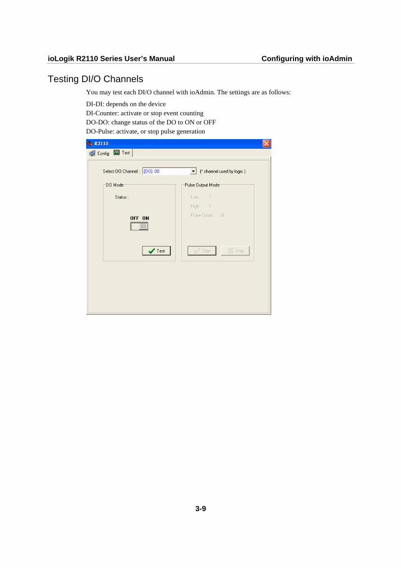
Testing DI/O Channels You may test each DI/O channel with ioAdmin. The settings are as follows:
DI-DI: depends on the device DI-Counter: activate or stop event counting DO-DO: change status of the DO to ON or OFF DO-Pulse: activate, or stop pulse generation

ioLogik R2110 Series User’s Manual Configuring with ioAdmin
3-10
Configuring Digital Input Channels The ioLogik R2110 is equipped with 12 digital inputs that can be set individually to DI or Event Counter mode. In DI mode, the specification is as follows:
Dry contact Logic 0 (OFF): short to GND Logic 1 (ON): open
Wet contact Logic 0 (OFF): 0 to 3V Logic 1 (ON): 10 to 30V

ioLogik R2110 Series User’s Manual Configuring with ioAdmin
3-11
In Event Counter mode, the ioLogik R2110’s DI can connect to the limit switch or the proximity switch and can count the time based on the ON/OFF status. You can set the trigger for two modes, Lo to Hi, or Hi to Lo. When setting the trigger as Lo to Hi, the counter value increases when the switch is pushed. When setting the trigger as Hi to Lo, the counter value increases when the switch is pushed and released.
To eliminate the problem of bouncing with the switch, the ioLogik R2110 provides software filtering. It is configurable in multiples of 10 ms. For example, a setting of 2 would mean a 20 ms filter (2 x 10 ms). The maximum value allowed by the software filter is 65535.
Setting the filter to “0” causes the system to filter all signals.
The sampling rate of the counter is 50 Hz. This function is designed for low speed switching, not for motor control. You may also configure how the counter is handled when the ioLogik R2110 is powered on or in safe status. If Start is checked off in the Power On Settings, the counter will begin counting events as soon as the ioLogikR2110 is powered on. If Start/Continue is checked off, the counter will start or continue counting events when the ioLogik R2110 switches to safe status as configured by the Host Connection Watchdog.

ioLogik R2110 Series User’s Manual Configuring with ioAdmin
3-12
Configuring Digital Output Channels The ioLogik R2110 is equipped with 8 digital output (sink) channels that can be set individually to DO or Pulse Output mode. In DO mode, the specification is Logic 0 (OFF)=open; Logic 1 (ON)=short:
You may also configure whether the DO status is set to ON or OFF when the ioLogik 2110 is powered on or in safe status, under the Power On Settings and the Safe Status Settings.

ioLogik R2110 Series User’s Manual Configuring with ioAdmin
3-13
In Pulse Output mode, the selected digital output channel will generate a square wave as specified in the pulse mode parameters. The Low and High parameters are in multiples of 10.0 ms, so a setting of 100 for both Low and High would generate a square wave with a 2-second cycle in total (Low wave is 100 x 10ms, or 1000 ms, and High wave is 100 x 10 ms, or 1000 ms, for a total of 2000 ms or 2 sec). The Output parameter configures the number of pulses to send. Setting it for 0 pulses tells the system to send an unlimited number of pulses. The maximum value for the Low and High parameters is 65535, and the maximum value for the Output parameter is 232.
You may also configure how the output pulse is handled when the ioLogik R2110 is powered on or in safe status. If Start is checked off in the Power On Settings, the output pulse will commence as soon as the ioLogikR2110 is powered on. If Start/Continue is checked off, the output pulse will start or continue when the ioLogik R2110 switches to safe status as configured by the Host Connection Watchdog.
About Power On Settings ioAdmin allows you to configure the status or behavior of each DI/O channel when the ioLogik R2110 is initially powered on. You can access this setting by double-clicking on any channel in the I/O Status tab. For DI channels in Event Counter mode, you can configure whether or not counting begins at power up. For DO channels in DO mode, you can configure whether or not the DO is set to OFF or ON at power up. For DO channels in Output Pulse mode, you can configure whether or not the output pulse commences at power up.
About Safe Status Settings With the ioLogik R2110, you have control over how your DI/O channels respond during a break in RS-485 communication, rather than having all activity simply cease. This is done through the Safe Status settings and the Host Connection Watchdog.

ioLogik R2110 Series User’s Manual Configuring with ioAdmin
3-14
Safe Status is controlled by the ioLogik R2110’s Host Connection Watchdog and is activated after a break in RS-485 communication for a specified time interval. When the ioLogik R2110 enters Safe Status (i.e. after the break in RS-485 communication), your DI/O channel will respond as configured in its Safe Status settings.
For example, you could configure a DO channel to start output pulses at Safe Status. When the Host Connection Watchdog determines that a break in RS-485 communication has occurred, it activates Safe Status, and that DO channel will begin output pulses. You could configure a DI channel that is in Event Counter mode to continue counting events in Safe Status, so that even after a break in communication, that DI channel will continue counting events.
If the Host Connection Watchdog is not enabled, the ioLogikR2110 will never enter Safe Status. This means that if the Host Connection Watchdog is not enabled, your Safe Status settings will have no effect.
To configure a DI/O channel’s Safe Status settings, double-click on the channel in the I/O Status tab. For DI channels in Event Counter mode, you can configure whether or not counting starts or continues when Safe Status has been activated. For DO channels in DO mode, you can configure whether or not the DO is set to OFF or ON at Safe Status. For DO channels in Output Pulse mode, you can configure whether or not the output pulse commences or continues at Safe Status.
Host Connection Watchdog The activates Safe Status when RS-485 communication between the PC and the ioLogik R2110 has been disrupted for a configurable amount of time. You may configure the Watchdog by going to the Watchdog tab.
By default, the Watchdog is disabled. When the Watchdog is enabled and a timeout occurs, the ioLogik R2110 will enter Safe Status, and you may configure how each DI/O channel responds in the channel’s Safe Status settings.
To enable the Watchdog, check off Enable Host Connection Watchdog, set the Timeout value, and restart the server. With Watchdog enabled, the ioLogik R2110 will first wait after a RS-485 communications disruption before entering Safe Status. The amount of time it will wait is set by the Timeout value.
When a timeout occurs, a warning will be visible in the Watchdog tab, stating Host Connection Lost Alarmed! You may click on Clear Alarm to reset the Watchdog and deactivate Safe Status. If there is another disruption in communication, the Watchdog will activate Safe Status again.
ioLogik R2110 Series User’s Manual Configuring with ioAdmin
3-15
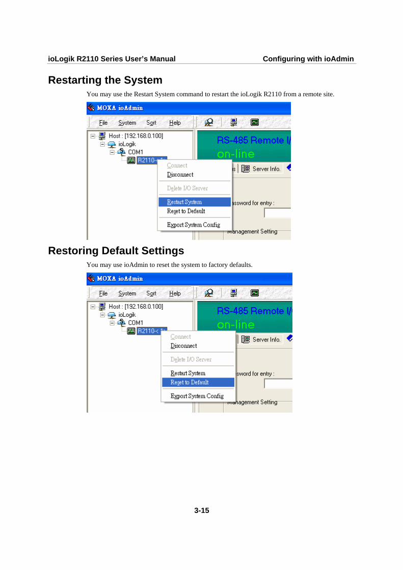
Restarting the System You may use the Restart System command to restart the ioLogik R2110 from a remote site.
Restoring Default Settings You may use ioAdmin to reset the system to factory defaults.

ioLogik R2110 Series User’s Manual Configuring with ioAdmin
3-16
Exporting ioLogik R2110 Settings ioLogik R2110 settings can be exported to a text file for backup.
ioLogik 2000 RS-485 I/O Server Configuration ============================================ Date: 2006/6/25 Time: 下午 11:21:33 1. Model -------- IOLOGIK R2110 - RS-485 Remote I/O Server (12DI + 8DO) 2. System and I/O Configurations -------------------------------- DI00 DI -n/a- DI01 DI -n/a- DI02 DI -n/a- DI03 DI -n/a- DI04 DI -n/a- DI05 DI -n/a- DI06 DI -n/a- DI07 DI -n/a- DI08 DI -n/a- DI09 DI -n/a- DI10 DI -n/a- DI11 DI -n/a- DO00 DO PWR ON=Off, Safe status=Off DO01 DO PWR ON=Off, Safe status=On DO02 DO PWR ON=Off, Safe status=Off DO03 DO PWR ON=Off, Safe status=Off DO04 DO PWR ON=Off, Safe status=Off DO05 DO PWR ON=Off, Safe status=Off DO06 DO PWR ON=Off, Safe status=Off DO07 DO PWR ON=Off, Safe status=Off

ioLogik R2110 Series User’s Manual Configuring with ioAdmin
3-17
3. Modbus address table ----------------------- Channel No. I/O type Modbus reference Modbus address (Dec, Hex) DI00 Input 10001 0000, 0x0000 DI01 Input 10002 0001, 0x0001 DI02 Input 10003 0002, 0x0002 DI03 Input 10004 0003, 0x0003 DI04 Input 10005 0004, 0x0004 DI05 Input 10006 0005, 0x0005 DI06 Input 10007 0006, 0x0006 DI07 Input 10008 0007, 0x0007 DI08 Input 10009 0008, 0x0008 DI09 Input 10010 0009, 0x0009 DI10 Input 10011 0010, 0x000A DI11 Input 10012 0011, 0x000B DO00 Output 00001 0000, 0x0000 DO01 Output 00002 0001, 0x0001 DO02 Output 00003 0002, 0x0002 DO03 Output 00004 0003, 0x0003 DO04 Output 00005 0004, 0x0004 DO05 Output 00006 0005, 0x0005 DO06 Output 00007 0006, 0x0006 DO07 Output 00008 0007, 0x0007 <END>
Password Protection The ioLogik R2110 can be protected by password under the Management tab. The login and password restrict access to configuration and other functions, such as Host Connection Watchdog or firmware updates. If you forget the password, press Reset to clear the password and reset all settings back to their factory defaults. NOTE: The Reset button is located at the top of the ioLogik R2110. Hold the reset button down for 5 seconds to reboot the system back to factory defaults.
Firmware Update Once you have logged in under the Management tab, you can use ioAdmin to remotely download firmware for the ioLogik R2110. You can download the newest firmware at Moxa's website. The file name of the firmware will be in this format: XXXX.2kp.

ioLogik R2110 Series User’s Manual Configuring with ioAdmin
3-18
Firmware Upgrade Screens

AA Appendix A Modbus/RTU Address Mappings
ioLogik R2110 Modbus Mapping 0xxxx Read/Write Coils (Support Functions 1, 5, 15)
Reference Address Data Type Description 00001 0x0000 1 bit CH0 DO Value 0: Off 1: On 00002 0x0001 1 bit CH1 DO Value 0: Off 1: On 00003 0x0002 1 bit CH2 DO Value 0: Off 1: On 00004 0x0003 1 bit CH3 DO Value 0: Off 1: On 00005 0x0004 1 bit CH4 DO Value 0: Off 1: On 00006 0x0005 1 bit CH5 DO Value 0: Off 1: On 00007 0x0006 1 bit CH6 DO Value 0: Off 1: On 00008 0x0007 1 bit CH7 DO Value 0: Off 1: On 00009 0x0008 1 bit CH0 DO Power-On Value 0: Off 1: On 00010 0x0009 1 bit CH1 DO Power-On Value 0: Off 1: On 00011 0x000A 1 bit CH2 DO Power-On Value 0: Off 1: On 00012 0x000B 1 bit CH3 DO Power-On Value 0: Off 1: On 00013 0x000C 1 bit CH4 DO Power-On Value 0: Off 1: On 00014 0x000D 1 bit CH5 DO Power-On Value 0: Off 1: On 00015 0x000E 1 bit CH6 DO Power-On Value 0: Off 1: On 00016 0x000F 1 bit CH7 DO Power-On Value 0: Off 1: On 00017 0x0010 1 bit CH0 DO Safe Value 0: Off 1: On 00018 0x0011 1 bit CH1 DO Safe Value 0: Off 1: On 00019 0x0012 1 bit CH2 DO Safe Value 0: Off 1: On 00020 0x0013 1 bit CH3 DO Safe Value 0: Off 1: On 00021 0x0014 1 bit CH4 DO Safe Value 0: Off 1: On 00022 0x0015 1 bit CH5 DO Safe Value 0: Off 1: On 00023 0x0016 1 bit CH6 DO Safe Value 0: Off 1: On 00024 0x0017 1 bit CH7 DO Safe Value 0: Off 1: On 00025 0x0018 1 bit CH0 DO Pulse Operate Status 0: Off 1: On 00026 0x0019 1 bit CH1 DO Pulse Operate Status 0: Off 1: On 00027 0x001A 1 bit CH2 DO Pulse Operate Status 0: Off 1: On 00028 0x001B 1 bit CH3 DO Pulse Operate Status 0: Off 1: On 00029 0x001C 1 bit CH4 DO Pulse Operate Status 0: Off 1: On 00030 0x001D 1 bit CH5 DO Pulse Operate Status 0: Off 1: On 00031 0x001E 1 bit CH6 DO Pulse Operate Status 0: Off 1: On 00032 0x001F 1 bit CH7 DO Pulse Operate Status 0: Off 1: On 00033 0x0020 1 bit CH0 DO Power-On Pulse Operate Status 0: Off 1: On 00034 0x0021 1 bit CH1 DO Power-On Pulse Operate Status 0: Off 1: On

ioLogik R2110 Series User’s Manual Modbus/RTU Address Mappings
A-2
Reference Address Data Type Description 00035 0x0022 1 bit CH2 DO Power-On Pulse Operate Status 0: Off 1: On 00036 0x0023 1 bit CH3 DO Power-On Pulse Operate Status 0: Off 1: On 00037 0x0024 1 bit CH4 DO Power-On Pulse Operate Status 0: Off 1: On 00038 0x0025 1 bit CH5 DO Power-On Pulse Operate Status 0: Off 1: On 00039 0x0026 1 bit CH6 DO Power-On Pulse Operate Status 0: Off 1: On 00040 0x0027 1 bit CH7 DO Power-On Pulse Operate Status 0: Off 1: On 00041 0x0028 1 bit CH0 DO Safe Pulse Operate Status 0: Off 1: On 00042 0x0029 1 bit CH1 DO Safe Pulse Operate Status 0: Off 1: On 00043 0x002A 1 bit CH2 DO Safe Pulse Operate Status 0: Off 1: On 00044 0x002B 1 bit CH3 DO Safe Pulse Operate Status 0: Off 1: On 00045 0x002C 1 bit CH4 DO Safe Pulse Operate Status 0: Off 1: On 00046 0x002D 1 bit CH5 DO Safe Pulse Operate Status 0: Off 1: On 00047 0x002E 1 bit CH6 DO Safe Pulse Operate Status 0: Off 1: On 00048 0x002F 1 bit CH7 DO Safe Pulse Operate Status 0: Off 1: On 00049 0x0030 1 bit CH0 DI Counter Status 0: Off 1: On 00040 0x0031 1 bit CH1 DI Counter Status 0: Off 1: On 00041 0x0032 1 bit CH2 DI Counter Status 0: Off 1: On 00042 0x0033 1 bit CH3 DI Counter Status 0: Off 1: On 00043 0x0034 1 bit CH4 DI Counter Status 0: Off 1: On 00044 0x0035 1 bit CH5 DI Counter Status 0: Off 1: On 00045 0x0036 1 bit CH6 DI Counter Status 0: Off 1: On 00056 0x0037 1 bit CH7 DI Counter Status 0: Off 1: On 00057 0x0038 1 bit CH8 DI Counter Status 0: Off 1: On 00058 0x0039 1 bit CH9 DI Counter Status 0: Off 1: On 00059 0x003A 1 bit CH10 DI Counter Status 0: Off 1: On 00060 0x003B 1 bit CH11 DI Counter Status 0: Off 1: On 00061 0x003C 1 bit CH0 DI Clear Counter Value read always: 0
Write: 1: Clear counter value 0: return Illegal Data Value
00062 0x003D 1 bit CH1 DI Clear Counter Value read always: 0 Write: 1: Clear counter value 0: return Illegal Data Value
00063 0x003E 1 bit CH2 DI Clear Counter Value read always: 0 Write: 1: Clear counter value 0: return Illegal Data Value
00064 0x003F 1 bit CH3 DI Clear Counter Value read always: 0 Write: 1: Clear counter value 0: return Illegal Data Value
00065 0x0040 1 bit CH4 DI Clear Counter Value read always: 0 Write: 1: Clear counter value 0: return Illegal Data Value
00066 0x0041 1 bit CH5 DI Clear Counter Value read always: 0 Write: 1: Clear counter value 0: return Illegal Data Value
00067 0x0042 1 bit CH6 DI Clear Counter Value read always: 0 Write: 1: Clear counter value 0: return Illegal Data Value
00068 0x0043 1 bit CH7 DI Clear Counter Value read always: 0 Write: 1: Clear counter value 0: return Illegal Data Value
ioLogik R2110 Series User’s Manual Modbus/RTU Address Mappings
A-3
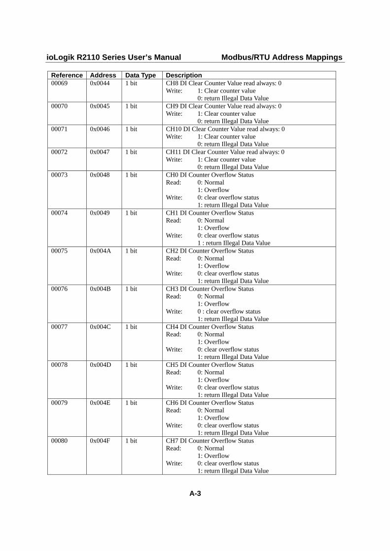
Reference Address Data Type Description 00069 0x0044 1 bit CH8 DI Clear Counter Value read always: 0
Write: 1: Clear counter value 0: return Illegal Data Value
00070 0x0045 1 bit CH9 DI Clear Counter Value read always: 0 Write: 1: Clear counter value 0: return Illegal Data Value
00071 0x0046 1 bit CH10 DI Clear Counter Value read always: 0 Write: 1: Clear counter value 0: return Illegal Data Value
00072 0x0047 1 bit CH11 DI Clear Counter Value read always: 0 Write: 1: Clear counter value 0: return Illegal Data Value
00073 0x0048 1 bit CH0 DI Counter Overflow Status Read: 0: Normal 1: Overflow Write: 0: clear overflow status 1: return Illegal Data Value
00074 0x0049 1 bit CH1 DI Counter Overflow Status Read: 0: Normal 1: Overflow Write: 0: clear overflow status 1 : return Illegal Data Value
00075 0x004A 1 bit CH2 DI Counter Overflow Status Read: 0: Normal 1: Overflow Write: 0: clear overflow status 1: return Illegal Data Value
00076 0x004B 1 bit CH3 DI Counter Overflow Status Read: 0: Normal 1: Overflow Write: 0 : clear overflow status 1: return Illegal Data Value
00077 0x004C 1 bit CH4 DI Counter Overflow Status Read: 0: Normal 1: Overflow Write: 0: clear overflow status 1: return Illegal Data Value
00078 0x004D 1 bit CH5 DI Counter Overflow Status Read: 0: Normal 1: Overflow Write: 0: clear overflow status 1: return Illegal Data Value
00079 0x004E 1 bit CH6 DI Counter Overflow Status Read: 0: Normal 1: Overflow Write: 0: clear overflow status 1: return Illegal Data Value
00080 0x004F 1 bit CH7 DI Counter Overflow Status Read: 0: Normal 1: Overflow Write: 0: clear overflow status 1: return Illegal Data Value

ioLogik R2110 Series User’s Manual Modbus/RTU Address Mappings
A-4
Reference Address Data Type Description 00081 0x0050 1 bit CH8 DI Counter Overflow Status
Read: 0: Normal 1: Overflow Write: 0: clear overflow status 1: return Illegal Data Value
00082 0x0051 1 bit CH9 DI Counter Overflow Status Read: 0: Normal 1: Overflow Write: 0: clear overflow status 1: return Illegal Data Value
00083 0x0052 1 bit CH10 DI Counter Overflow Status Read: 0: Normal 1: Overflow Write: 0: clear overflow status 1: return Illegal Data Value
00084 0x0053 1 bit CH11 DI Counter Overflow Status Read: 0: Normal 1: Overflow Write: 0: clear overflow status 1: return Illegal Data Value
00085 0x0054 1 bit CH0 DI Counter Trigger : 0=Low to High, 1=High to Low 00086 0x0055 1 bit CH1 DI Counter Trigger : 0=Low to High, 1=High to Low 00087 0x0056 1 bit CH2 DI Counter Trigger : 0=Low to High, 1=High to Low 00088 0x0057 1 bit CH3 DI Counter Trigger : 0=Low to High, 1=High to Low 00089 0x0058 1 bit CH4 DI Counter Trigger : 0=Low to High, 1=High to Low 00090 0x0059 1 bit CH5 DI Counter Trigger : 0=Low to High, 1=High to Low 00091 0x005A 1 bit CH6 DI Counter Trigger : 0=Low to High, 1=High to Low 00092 0x005B 1 bit CH7 DI Counter Trigger : 0=Low to High, 1=High to Low 00093 0x005C 1 bit CH8 DI Counter Trigger : 0=Low to High, 1=High to Low 00094 0x005D 1 bit CH9 DI Counter Trigger : 0=Low to High, 1=High to Low 00095 0x005E 1 bit CH10 DI Counter Trigger : 0=Low to High, 1=High to Low 00096 0x005F 1 bit CH11 DI Counter Trigger : 0=Low to High, 1=High to Low 00097 0x0060 1 bit CH0 DI Counter Power-On Status 0: Off 1: On 00098 0x0061 1 bit CH1 DI Counter Power-On Status 0: Off 1: On 00099 0x0062 1 bit CH2 DI Counter Power-On Status 0: Off 1: On 00100 0x0063 1 bit CH3 DI Counter Power-On Status 0: Off 1: On 00101 0x0064 1 bit CH4 DI Counter Power-On Status 0: Off 1: On 00102 0x0065 1 bit CH5 DI Counter Power-On Status 0: Off 1: On 00103 0x0066 1 bit CH6 DI Counter Power-On Status 0: Off 1: On 00104 0x0067 1 bit CH7 DI Counter Power-On Status 0: Off 1: On 00105 0x0068 1 bit CH8 DI Counter Power-On Status 0: Off 1: On 00106 0x0069 1 bit CH9 DI Counter Power-On Status 0: Off 1: On 00107 0x006A 1 bit CH10 DI Counter Power-On Status 0: Off 1: On 00108 0x006B 1 bit CH11 DI Counter Power-On Status 0: Off 1: On 00109 0x006C 1 bit CH0 DI Counter Safe Status 0: Off 1: On 00110 0x006D 1 bit CH1 DI Counter Safe Status 0: Off 1: On 00111 0x006E 1 bit CH2 DI Counter Safe Status 0: Off 1: On 00112 0x006F 1 bit CH3 DI Counter Safe Status 0: Off 1: On 00113 0x0070 1 bit CH4 DI Counter Safe Status 0: Off 1: On 00114 0x0071 1 bit CH5 DI Counter Safe Status 0: Off 1: On 00115 0x0072 1 bit CH6 DI Counter Safe Status 0: Off 1: On
ioLogik R2110 Series User’s Manual Modbus/RTU Address Mappings
A-5
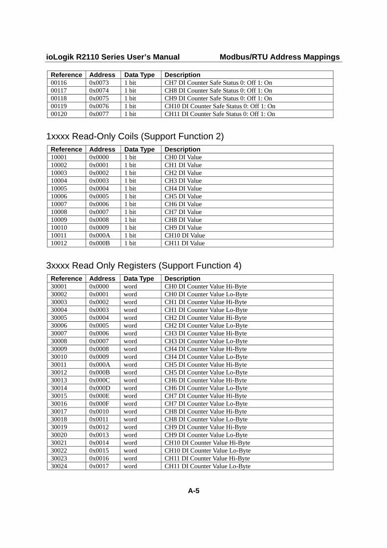
Reference Address Data Type Description 00116 0x0073 1 bit CH7 DI Counter Safe Status 0: Off 1: On 00117 0x0074 1 bit CH8 DI Counter Safe Status 0: Off 1: On 00118 0x0075 1 bit CH9 DI Counter Safe Status 0: Off 1: On 00119 0x0076 1 bit CH10 DI Counter Safe Status 0: Off 1: On 00120 0x0077 1 bit CH11 DI Counter Safe Status 0: Off 1: On
1xxxx Read-Only Coils (Support Function 2) Reference Address Data Type Description 10001 0x0000 1 bit CH0 DI Value 10002 0x0001 1 bit CH1 DI Value 10003 0x0002 1 bit CH2 DI Value 10004 0x0003 1 bit CH3 DI Value 10005 0x0004 1 bit CH4 DI Value 10006 0x0005 1 bit CH5 DI Value 10007 0x0006 1 bit CH6 DI Value 10008 0x0007 1 bit CH7 DI Value 10009 0x0008 1 bit CH8 DI Value 10010 0x0009 1 bit CH9 DI Value 10011 0x000A 1 bit CH10 DI Value 10012 0x000B 1 bit CH11 DI Value
3xxxx Read Only Registers (Support Function 4) Reference Address Data Type Description 30001 0x0000 word CH0 DI Counter Value Hi-Byte 30002 0x0001 word CH0 DI Counter Value Lo-Byte 30003 0x0002 word CH1 DI Counter Value Hi-Byte 30004 0x0003 word CH1 DI Counter Value Lo-Byte 30005 0x0004 word CH2 DI Counter Value Hi-Byte 30006 0x0005 word CH2 DI Counter Value Lo-Byte 30007 0x0006 word CH3 DI Counter Value Hi-Byte 30008 0x0007 word CH3 DI Counter Value Lo-Byte 30009 0x0008 word CH4 DI Counter Value Hi-Byte 30010 0x0009 word CH4 DI Counter Value Lo-Byte 30011 0x000A word CH5 DI Counter Value Hi-Byte 30012 0x000B word CH5 DI Counter Value Lo-Byte 30013 0x000C word CH6 DI Counter Value Hi-Byte 30014 0x000D word CH6 DI Counter Value Lo-Byte 30015 0x000E word CH7 DI Counter Value Hi-Byte 30016 0x000F word CH7 DI Counter Value Lo-Byte 30017 0x0010 word CH8 DI Counter Value Hi-Byte 30018 0x0011 word CH8 DI Counter Value Lo-Byte 30019 0x0012 word CH9 DI Counter Value Hi-Byte 30020 0x0013 word CH9 DI Counter Value Lo-Byte 30021 0x0014 word CH10 DI Counter Value Hi-Byte 30022 0x0015 word CH10 DI Counter Value Lo-Byte 30023 0x0016 word CH11 DI Counter Value Hi-Byte 30024 0x0017 word CH11 DI Counter Value Lo-Byte

ioLogik R2110 Series User’s Manual Modbus/RTU Address Mappings
A-6
4xxxx Read/Write Registers (Support Functions 3, 6, 16) Reference Address Data Type Description 40001 0x0000 word CH0 DO Pulse Output Count Value Hi-Word 40002 0x0001 word CH0 DO Pulse Output Count Value Lo-Word 40003 0x0002 word CH1 DO Pulse Output Count Value Hi-Word 40004 0x0003 word CH1 DO Pulse Output Count Value Lo-Word 40005 0x0004 word CH2 DO Pulse Output Count Value Hi-Word 40006 0x0005 word CH2 DO Pulse Output Count Value Lo-Word 40007 0x0006 word CH3 DO Pulse Output Count Value Hi-Word 40008 0x0007 word CH3 DO Pulse Output Count Value Lo-Word 40009 0x0008 word CH4 DO Pulse Output Count Value Hi-Word 40010 0x0009 word CH4 DO Pulse Output Count Value Lo-Word 40011 0x000A word CH5 DO Pulse Output Count Value Hi-Word 40012 0x000B word CH5 DO Pulse Output Count Value Lo-Word 40013 0x000C word CH6 DO Pulse Output Count Value Hi-Word 40014 0x000D word CH6 DO Pulse Output Count Value Lo-Word 40015 0x000E word CH7 DO Pulse Output Count Value Hi-Word 40016 0x000F word CH7 DO Pulse Output Count Value Lo-Word 40017 0x0010 word CH0 DO Pulse Low Signal Width 40018 0x0011 word CH1 DO Pulse Low Signal Width 40019 0x0012 word CH2 DO Pulse Low Signal Width 40020 0x0013 word CH3 DO Pulse Low Signal Width 40021 0x0014 word CH4 DO Pulse Low Signal Width 40022 0x0015 word CH5 DO Pulse Low Signal Width 40023 0x0016 word CH6 DO Pulse Low Signal Width 40024 0x0017 word CH7 DO Pulse Low Signal Width 40025 0x0018 word CH0 DO Pulse High Signal Width 40026 0x0019 word CH1 DO Pulse High Signal Width 40027 0x001A word CH2 DO Pulse High Signal Width 40028 0x001B word CH3 DO Pulse High Signal Width 40029 0x001C word CH4 DO Pulse High Signal Width 40030 0x001D word CH5 DO Pulse High Signal Width 40031 0x001E word CH6 DO Pulse High Signal Width 40032 0x001F word CH7 DO Pulse High Signal Width 40033 0x0020 word CH0 DO Mode 0: DO
1: Pulse 40034 0x0021 word CH1 DO Mode 0: DO
1: Pulse 40035 0x0022 word CH2 DO Mode 0: DO
1: Pulse 40036 0x0023 word CH3 DO Mode 0: DO
1: Pulse 40037 0x0024 word CH4 DO Mode 0: DO
1: Pulse 40038 0x0025 word CH5 DO Mode 0: DO
1: Pulse 40039 0x0026 word CH6 DO Mode 0: DO
1: Pulse 40040 0x0027 word CH7 DO Mode 0: DO
1: Pulse

ioLogik R2110 Series User’s Manual Modbus/RTU Address Mappings
A-7
Reference Address Data Type Description 40041 0x0028 word CH0 DI / Counter Filter 40042 0x0029 word CH1 DI / Counter Filter 40043 0x002A word CH2 DI / Counter Filter 40044 0x002B word CH3 DI / Counter Filter 40045 0x002C word CH4 DI / Counter Filter 40046 0x002D word CH5 DI / Counter Filter 40047 0x002E word CH6 DI / Counter Filter 40048 0x002F word CH7 DI / Counter Filter 40049 0x0030 word CH8 DI / Counter Filter 40050 0x0031 word CH9 DI / Counter Filter 40051 0x0032 word CH10 DI / Counter Filter 40052 0x0033 word CH11 DI / Counter Filter 40053 0x0034 word CH0 DI Mode 0: DI
1: Counter Others: return Illegal Data Value
40054 0x0035 word CH1 DI Mode 0: DI 1: Counter Others: return Illegal Data Value
40055 0x0036 word CH2 DI Mode 0: DI 1: Counter Others: return Illegal Data Value
40056 0x0037 word CH3 DI Mode 0: DI 1: Counter Others: return Illegal Data Value
40057 0x0038 word CH4 DI Mode 0: DI 1: Counter Others: return Illegal Data Value
40058 0x0039 word CH5 DI Mode 0: DI 1: Counter Others: return Illegal Data Value
40059 0x003A word CH6 DI Mode 0: DI 1: Counter Others: return Illegal Data Value
40060 0x003B word CH7 DI Mode 0: DI 1: Counter Others: return Illegal Data Value
40061 0x003C word CH8 DI Mode 0: DI 1: Counter Others: return Illegal Data Value
40062 0x003D word CH9 DI Mode 0: DI 1: Counter Others: return Illegal Data Value
40063 0x003E word CH10 DI Mode 0: DI 1: Counter Others: return Illegal Data Value
40064 0x003F word CH11 DI Mode 0: DI 1: Counter Others: return Illegal Data Value

ioLogik R2110 Series User’s Manual Modbus/RTU Address Mappings
A-8
Function 8 Sub-function Data Field (Request) Data Field (Response) Description 0x0001 0x0000 Echo Request Data Reboot 0x0001 0xFF00 Echo Request Data Reset to Factory defaults
BB Appendix B Factory Default Settings
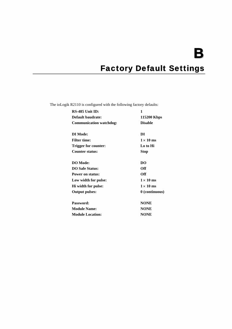
The ioLogik R2110 is configured with the following factory defaults:
RS-485 Unit ID: 1 Default baudrate: 115200 Kbps Communication watchdog: Disable DI Mode: DI Filter time: 1 × 10 ms Trigger for counter: Lo to Hi Counter status: Stop DO Mode: DO DO Safe Status: Off Power on status: Off Low width for pulse: 1 × 10 ms Hi width for pulse: 1 × 10 ms Output pulses: 0 (continuous) Password: NONE Module Name: NONE Module Location: NONE

CC Appendix C Port Pinout Diagrams
Serial Port Pinouts ioLogik R2110 RS-485 Network Adapter Pin Assignment

DD Appendix D Service Information
This appendix contains information on how to contact MOXA for information about this and other MOXA products, as well as the procedure for reporting problems.
In this appendix, we cover the following topics.
MOXA Internet Services Problem Report Form Product Return Procedure

ioLogik R2110 Series User’s Manual Service Information
D-2
MOXA Internet Services Customer satisfaction is our primary concern. To ensure that customers receive the full benefit of our products, MOXA Internet Services has been set up to provide technical support, driver updates, product information, and user’s manual updates.
The following services are provided
E-mail for technical support .............. [email protected]
Websites for product information:
........................ http://www.moxa.com or
........................ http://www.moxa.com.tw

ioLogik R2110 Series User’s Manual Service Information
D-3
Problem Report Form
MOXA ioLogik R2110 RS-485 Remote I/O Server Customer name: Company: Tel: Fax: Email: Date: Product Model: ioLogik R2110 RS-485 Remote I/O Server Serial Number: _________________
Problem Description: Please describe the symptoms of the problem as clearly as possible, including any error messages you see. A clearly written description of the problem will allow us to reproduce the symptoms and expedite the repair of your product.

ioLogik R2110 Series User’s Manual Service Information
D-4
Product Return Procedure For product repair, exchange, or refund, please follow these instructions:
Provide evidence of original purchase.
Obtain a Product Return Agreement (PRA) from the sales representative or dealer.
Fill out the Problem Report Form (PRF). Include as much detail as possible to expedite diagnosis of your product.
Carefully pack the product in an anti-static package and send it, pre-paid, to the dealer. The PRA should be visible on the outside of the package and should include a description of the problem along with the return address and telephone number.