Embed Size (px)
Citation preview

For further assistanceplease contact us at:
Worldwide Headquarters2195 Keating Cross RoadSaanichton, BCCanada V8M 2A5Tel: 1-250-652-7100Fax: 1-250-652-0411Email: [email protected]
www.pwrm.com
© 2004 Power MeasurementPrinted in CanadaRevision Date: Nov. 15, 200470000-0193-01
Notices Danger
This symbol indicates the presence of dangerous voltage within and outside the product enclosure that may constitute a risk of electric shock, serious injury or death to persons if proper precautions are not followed.
Caution
This symbol alerts the user to the presence of hazards that may cause minor or moderate injury to persons, damage to property or damage to the device itself, if proper precautions are not followed.
Note
This symbol directs the user’s attention to important installation, operating and maintenance instructions.
Installation ConsiderationsInstallation and maintenance of the ION 8000 series meter should only be performed by qualified, competent personnel that have appropriate training and experience with high voltage and current devices. The meter must be installed in accordance with all Local and National Electrical Codes.
DANGER
Failure to observe the following instructions may result in severe injury or death.
During normal operation of the ION 8000 series meter, hazardous voltages are present on its terminal strips, and throughout the connected potential transformer (PT), current transformer (CT), digital (status) input, control power and external I/O circuits. PT and CT secondary circuits are capable of generating lethal voltages and currents with their primary circuit energized. Follow standard safety precautions while performing any installation or service work (i.e. removing PT fuses, shorting CT secondaries, etc.).
The terminal strips on the meter base should not be user-accessible after installation.
Do not use digital output devices for primary protection functions. These include applications where the devices perform energy limiting functions or provide protection of people from injury. Do not use the ION 8000 series in situations where failure of the devices can cause injury or death, or cause sufficient energy to be released that can start a fire. The meter can be used for secondary protection functions.
Do not HIPOT/Dielectric test the digital (status) inputs, digital outputs, or communications terminals. Refer to the label on the ION 8000 series meter for the maximum voltage level the device can withstand.
CAUTION
Observe the following instructions, or permanent damage to the meter may occur.
The ION 8000 series meter offers a range of hardware options that affect input ratings. The ION 8000 series meter’s serial number label lists all equipped options. Applying current levels incompatible with the current inputs will permanently damage the meter. This document provides installation instructions applicable to each hardware option.
The ION 8000 series meter’s chassis ground must be properly connected to the switchgear earth ground for the noise and surge protection circuitry to function correctly. Failure to do so will void the warranty.
Terminal screw torque: Barrier‐type (current, voltage, and relay terminal screws: 1.35 Nm (1.00 ft‐lbs.) max. Captured‐wire type (digital inputs/outputs, communications, power supply: 0.90 Nm (0.66 ft‐lbs.) max.
FCC NoticeThis equipment has been tested and found to comply with the limits for a Class A digital device, pursuant to Part 15 of the FCC Rules. These limits are designed to provide reasonable protection against harmful interference when the equipment is operated in a commercial environment. This equipment generates, uses, and can radiate radio frequency energy and, if not installed and used in accordance with the instruction manual, may cause harmful interference to radio communications. Operation of this equipment in a residential area is likely to cause harmful interference in which case the user will be required to correct the interference at his own expense. The Ringer Equivalence Number (REN) for the ION 8000 series optional internal modem is 0.6. Connection to the ION 8000 series internal modem should be made via an FCC Part 68 compliant telephone cord (not supplied). The ION 8000 series cannot be used on a public coin phone service or party line services.
Network Compatibility Notice for the Internal ModemThe internal modem in meters equipped with this option is compatible with the telephone systems of most countries in the world, with the exception of Australia and New Zealand. Use in some countries may require modification of the internal modem’s initialization strings. If problems using the modem on your phone system occur, please contact Power Measurement Technical Support.
Standards Compliance

Limitation of LiabilityPower Measurement Ltd. (“Power Measurement”) reserves the right to make changes in the device or its specifications identified in this document without notice. Power Measurement advises customers to obtain the latest version of the device specifications before placing orders to verify that the information being relied upon by the customer is current.
Regardless of whether any remedy set forth herein fails of its essential purpose, except to the extent the following limitation is prohibited by applicable law, Power Measurement shall not, in any event or under any legal claim or theory (whether based on contract, indemnity, warranty, tort (including negligence and strict liability) or otherwise), be liable to the original purchaser or any other person or entity for special, indirect, incidental, punitive, liquidated, special or consequential damages whatsoever with respect to any purchased product, including, without limitation, business interruption, loss of use, profit or revenue, even if Power Measurement has been advised of the possibility of such damages. To the extent that a limitation or exclusion of consequential damages are prohibited by applicable law, then Power Measurement’s liability shall be limited to twice the amount of the relevant purchased product. Not to limit the foregoing, a) Power Measurement shall not be liable for any claim (other than a claim solely for the breach of one of the above Warranties that is made in accordance with the above described procedures) made by the original purchaser, its employees, agents, or contractors for any loss, damage, or expense incurred due to, caused by, or related to any purchased product; and b) the above Warranties are the original purchaser's exclusive remedy and Power Measurement hereby expressly disclaims all other warranties, express or implied, including, without limitation, warranties of non-infringement and the implied warranties of merchantability and fitness for a particular purpose.
These limited Warranties shall not apply to any product that has been subject to alteration, accident, misuse, abuse, neglect or failure to exactly follow Power Measurement's instructions for operation and maintenance. Any technical assistance provided by Power Measurement's personnel or representatives in system design shall be deemed to be a proposal and not a recommendation. The responsibility for determining the feasibility of such proposals rests with the original purchaser and should be tested by the original purchaser. It is the original purchaser’s responsibility to determine the suitability of any product and associated documentation for its purposes. The original purchaser acknowledges that 100% "up" time is not realizable because of possible hardware or software defects. The original purchaser recognizes that such defects and failures may cause inaccuracies or malfunctions. Only the terms expressed in these limited Warranties shall apply and no distributor, corporation or other entity, individual or employee of Power Measurement or any other entity is authorized to amend, modify or extend the Warranties in any way.
The information contained in this document is believed to be accurate at the time of publication, however, Power Measurement assumes no responsibility for any errors which may appear here and reserves the right to make changes without notice.
Power Measurement, ION, ION Enterprise, MeterM@il, WebMeter and “drive energy performance” are either registered trademarks or trademarks of Power Measurement. All other trademarks are property of their respective owners.
Covered by one or more of the following patents:
U.S. Patent No's 6792364, 6792337, 6751562, 6745138, 6737855, 6694270, 6687627, 6671654, 6671635, 6615147, 6611922, 6611773, 6563697, 6493644, 6397155, 6186842, 6185508, 6000034, 5995911, 5828576, 5736847, 5650936, D459259, D458863, D443541, D439535, D435471, D432934, D429655, D429533, D427533.

ION 8000 Series User Guide
Contents
Chapter 1 Introduction .................................................................. 7
Chapter 2 Front Panel ................................................................. 17
Chapter 3 Templates and Firmware ............................................. 39
Chapter 4 Basic Setup ................................................................. 45
Chapter 5 Security ...................................................................... 49
Chapter 6 Communications ......................................................... 71
Chapter 7 Third Party Protocols ................................................... 95
Chapter 8 Time ......................................................................... 111
Chapter 9 Demand ................................................................... 115
Chapter 10 Inputs / Outputs ....................................................... 123
Chapter 11 Energy Pulsing .......................................................... 133
Chapter 12 Logging .................................................................... 139
Chapter 13 Revenue ................................................................... 147
Chapter 14 Power Quality .......................................................... 157
Chapter 15 Displays ................................................................... 161
Chapter 16 TEST Mode ............................................................... 173
Chapter 17 Resets ...................................................................... 181
Chapter 18 Alerting .................................................................... 187
Chapter 19 Setpoints .................................................................. 193
Chapter 20 Power Availability .................................................... 197
Chapter 21 Reports .................................................................... 205
Chapter 22 Theory of Operation ................................................. 209
Chapter 23 Verifying Accuracy ................................................... 217

Page 7
1 IntroductionION 8300™, ION 8400™ and ION 8500™ meters provide revenue-accurate, true RMS measurements of voltage, current, power and energy, and are complemented by extensive I/O capabilities, comprehensive logging, and advanced power quality measurement and compliance verification functions. The meters come with an extensive selection of pre-configured data screens and measurements, so you can use the meters “out of the box” or customize them to fit your unique requirements.
ION 8000 series meters give you the tools to manage complex energy supply contracts that include commitments to power quality. You can also integrate the meters with ION® software or other energy management, SCADA, automation and billing systems, via Internet communications and multiple industry-standard communication channels and protocols including MV90.
In this chapter
ION 8000 Series Meters . . . . . . . . . . . . . . . . . . . . . . . . . . . . . . . . . . . . . . . 8
ION Meter in Enterprise Energy Management Systems . . . . . . . . . . . . . . . . 10Data Display and Analysis Tools . . . . . . . . . . . . . . . . . . . . . . . . . . . . . . . . . . . . . . . 10
The Front Panel ...................................................................................................... 11WebMeter® Internal Web Server Feature ......................................................... 11MeterM@il® Internal Email Server Feature ....................................................... 11XML Compatibility ............................................................................................... 11ION Enterprise™ Software .................................................................................. 11ION Setup™ Software .......................................................................................... 12MV90 ....................................................................................................................... 12
Communications Methods . . . . . . . . . . . . . . . . . . . . . . . . . . . . . . . . . . . . . . . . . . . . . 12Digital and Analog I/O Options . . . . . . . . . . . . . . . . . . . . . . . . . . . . . . . . . . . . . . . . . 12
Onboard I/O ........................................................................................................... 12Expanded I/O ......................................................................................................... 13The Meter is Factory-Configured and Ready to Operate ................................ 13

ION 8000 Series Meters ION 8000 Series User Guide
Page 8 Chapter 1 - Introduction
ION 8000 Series MetersION 8300, ION 8400 and ION 8500 meters are suited to a wide range of applications. The meters can be used as stand-alone devices, but their extensive capabilities are fully realized when used as part of an enterprise energy management (EEM) system.
Whether your company is an energy supplier, service provider or consumer, an EEM system gives you the real-time information and control needed to take control of energy cost, quality and reliability across your entire enterprise. It gives you an integrated solution to managing new billing structures, distributed generation, energy purchasing, energy cost control, and operational efficiency while maximizing uptime. Systems can span widely dispersed geographic locations and multiple points within each site. A single, shared system delivers a broad range of functionality that can satisfy the needs of many different groups within your enterprise.
ION® technology uniquely delivers the benefits of enterprise energy management through an efficient, economical, and scalable architecture using web-enabled software and intelligent metering and control devices. ION systems place intelligence everywhere it’s needed, delivering information and control to everyone that needs it, wherever they are. This gives all parties the necessary information to make the best energy decisions, and the control to act on them. A single, shared system delivers a broad range of functionality that can satisfy the needs of many different groups within an enterprise, while integrating seamlessly with existing systems.
ION Enterprise™ is a powerful web-ready software suite that can process, analyze, store, and share information from across your entire organization. Its compatibility and flexibility means you can introduce individual components, at a pace you decide, while maintaining your original investments. You can access information and alarms from any workstation, pager, PDA, or cell phone locally or around the world, in the format you require. You can also perform coordinated load and equipment control functions, either manually or automatically. ION software collects data automatically from ION meters and third-party devices, so you can manage a single site or a global network of devices. ION software and hardware products reduce cost of installation and ownership by leverage existing corporate networks and popular networking technologies, including serial, wireless, modem, Ethernet and Internet links.
A wide selection of ION intelligent metering and control devices are available, with choices to meet the specific needs of various key points within an enterprise. Devices offer a range of high accuracy metering, power quality and reliability analysis, data and event logging, alarming, control and communications.
This manual discusses ION 8000 series meter default functionality, as well as features and applications. Throughout the manual, the term “meter” refers to all three meter models. All differences between the models, such as a feature specific to one model, are indicated with the appropriate model number.
ION 8000 Series User Guide ION 8000 Series Meters
Chapter 1 - Introduction Page 9
These meters can be used effectively in numerous energy supply-side (utility) and demand-side applications. Some common meter applications are:
Revenue metering
Substation automation
Power quality monitoring (with Flicker)
Commercial/industrial operations metering
Demand and power factor control
SCADA (supervisory control and data acquisition)
Distributed generation (generator) monitoring and control
ION Meter in Enterprise Energy Management Systems ION 8000 Series User Guide
Page 10 Chapter 1 - Introduction
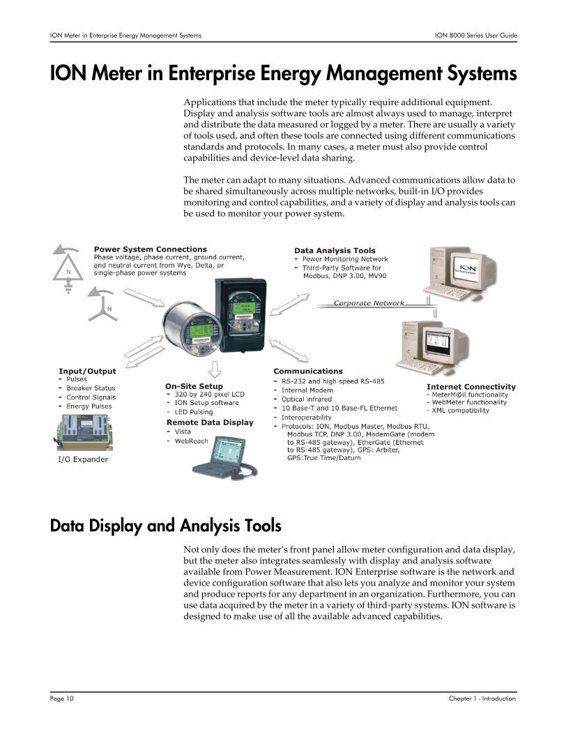
ION Meter in Enterprise Energy Management SystemsApplications that include the meter typically require additional equipment. Display and analysis software tools are almost always used to manage, interpret and distribute the data measured or logged by a meter. There are usually a variety of tools used, and often these tools are connected using different communications standards and protocols. In many cases, a meter must also provide control capabilities and device-level data sharing.
The meter can adapt to many situations. Advanced communications allow data to be shared simultaneously across multiple networks, built-in I/O provides monitoring and control capabilities, and a variety of display and analysis tools can be used to monitor your power system.
Data Display and Analysis ToolsNot only does the meter’s front panel allow meter configuration and data display, but the meter also integrates seamlessly with display and analysis software available from Power Measurement. ION Enterprise software is the network and device configuration software that also lets you analyze and monitor your system and produce reports for any department in an organization. Furthermore, you can use data acquired by the meter in a variety of third-party systems. ION software is designed to make use of all the available advanced capabilities.
ION 8000 Series User Guide Data Display and Analysis Tools
Chapter 1 - Introduction Page 11
The Front PanelLocal monitoring and standalone applications are facilitated by the meter’s front panel interface. The front panel combines real-time display features with limited device configuration functions. The front panel is often used in combination with an ION software system, providing an interface for field personnel.
WebMeter® Internal Web Server FeatureAn on-board Web server combined with an Ethernet port provides quick and easy access to real-time energy and basic power quality information without special software: this is WebMeter functionality. The built-in web pages display a range of energy and basic power quality information through the web-enabled device; these pages even support basic meter configuration tasks.
MeterM@il® Internal Email Server FeatureConfigure the meter to automatically email high-priority alarm notifications or scheduled system-status update messages to anyone, anywhere within the facility or around the world. Specify the type of event that triggers an email alert, such as power quality disturbances or logged data at any pre-determined interval, and have your ION software administrator program the meter to respond with a MeterM@il message when these events occur. MeterM@il messages can be received like any email message over a workstation, cell phone, pager, or PDA.
XML CompatibilityThe meters can exchange information using industry-standard XML format. This simple machine-readable format supports easy integration with custom reporting, spreadsheet, database, and other applications.
ION Enterprise™ SoftwareThe complete ION Enterprise software package enables the meter to be part of a fully networked information system with other meters and local and wide-area computer networks. ION Enterprise is recommended for all power monitoring systems where advanced analysis and control capabilities are required.
ION Enterprise provides tools for managing your power monitoring network, logging data, analyzing real-time and logged data, generating power system reports, and creating custom functionality at the meter level.
ION Enterprise also offers two ways to remotely view information through a web browser: the WebReach™ component of ION Enterprise, and Microsoft Terminal Services.
WebReach only requires an URL to display a meter’s real-time data and select views of historical and waveform data from a web browser; there is no client machine configuration. WebReach is a data display application; there is no control functionality available through it.
Microsoft Terminal Services enable full ION Enterprise functionality, including control features. Some client machine configuration is required.
Communications Methods ION 8000 Series User Guide
Page 12 Chapter 1 - Introduction
ION Setup™ SoftwareION Setup is a meter configuration tool designed specifically to configure and test meters. ION Setup offers an intuitive graphical interface for performing basic meter setup, installing templates into meters, viewing real-time and reset accumulated values, verifying meter calibration and measurements, and setting up advanced security.
MV90MV90 software (by Utility Translation Systems) is a multi-vendor translation system that can collect and analyze data from a variety of different brands of meters. One of the unique features of MV90 is its ability to log some information coming from several different brands of meters, each with unique database formats. MV90 manipulates this data without extensive knowledge of the device of origin. This is done by using TIM modules; each TIM module acts as a protocol translator specific to a device type, and it will convert some pre-defined data from a meter to the MV90 database format. The TIM module used for ION meters is called TIM_ION.
Communications MethodsThe meter can be integrated into various industry-standard networks. Data that is measured by the meter can be made available to other devices using the Modbus Master, Modbus RTU, Modbus TCP, and DNP 3.00 protocols, as well the MV-90 translation system. You can also configure the meter to import data from devices on these networks. With these advanced communications functions, the meter operates in most existing power monitoring systems. Any data display and analysis software that works with Modbus RTU or DNP 3.00 devices will also function with the meter.
The standard meter includes a selectable RS-232/RS-485 port (the factory default is RS-232), a high-speed RS-485 port, and an IrDA optical port for communications in the field. Order options include a 10Base-T Ethernet port or 10Base-FL fiber-optic port, and a 33.6 kbps internal modem (both FCC and CTR-21 compliant). Depending on the hardware options purchased, up to four separate ports can communicate simultaneously.
Digital and Analog I/O OptionsThe meter has digital inputs and outputs for a variety of applications. Additionally, a LED on the front panel is configured for energy pulsing. An optional I/O Expander product option is also available for digital and analog communication. There is separate I/O Expander documentation that accompanies this option.
Onboard I/OThe meter contains four Form C digital outputs and three Form A digital inputs. They can be used for monitoring breaker trips or send KYZ pulsing information to third-party system equipment.
ION 8000 Series User Guide Digital and Analog I/O Options
Chapter 1 - Introduction Page 13
Expanded I/OThe I/O Expander option extends the meter’s I/O capabilities. The digital I/O Expander model provides four Form A digital outputs, four Form C digital outputs, and eight Form A digital inputs. The analog I/O Expander model replaces the four form A digital outputs with analog outputs.
The Meter is Factory-Configured and Ready to OperateEven though the meter is fully customizable, it is shipped from the factory with many pre-configured functions. Once you have performed the installation and basic setup, all of the basic measurements, energy calculations and recording functions are ready to operate right out of the box. You may find that the factory configuration aptly serves your purposes, allowing you to forego additional configuration.
Using this Guide ION 8000 Series User Guide
Page 14 Chapter 1 - Introduction
Using this GuideThis User’s Guide is directed at three types of user: the typical user or operator, the system administrator, and the advanced user. You might not fit into any of these groups directly, or perhaps you are both an operator and an administrator. These classifications are intended to make this guide easier to navigate with respect to which information is appropriate to your needs.
Typical User or Operator
Most users simply want to display the data provided by the factory-configured meter. These users want fast access to data through the front panel, ION software, or a third-party protocol such as Modbus or DNP.
System Administrator or Manager
Some users need to make minor adjustments so that their meters “fit” their power systems: data recording intervals, demand sub-intervals and other parameters may need to be set before the meter’s setup is complete. These users will use the front panel, or ION software to change settings in the device’s operating software. (ION Enterprise is highly recommended.)
Advanced User or Systems Integrator
Advanced users may want to make use of the flexibility and power provided by the device’s operating software. These users will need to become familiar with the ION architecture, and the ION software tools used to customize the device’s operation.
SymbolsThe following symbols are used in this manual to warn you about the risk of injury, damage to the equipment, inconvenience if the proper procedure is not followed, or additional information you may want to consider.
CAUTION
This symbol alerts you to things that may cause loss of data, damage to your computer or your device.
DANGER
This symbol alerts you to things that may cause serious injury to a person. Only qualified, properly trainedpersonnel should perform these procedures.
NOTE
A note provides you with additional information that you might want to consider.
TIP
This symbol draws your attention to information that will help you perform a task more quickly or easily.
ION 8000 Series User Guide Using this Guide
Chapter 1 - Introduction Page 15
Terminology
PDF DocumentsThis manual is also provided in PDF (Portable Document Format) at our website: www.pwrm.com.
Use Acrobat® Reader® to view and print the PDF version of the manual. When printing the manual, please print the entire manual, including the copyright and disclaimer statements.
The PDF files for all Power Measurement products are available from the Power Measurement web site. Each Power Measurement device has installation information and a user's guide to teach you about the features of your device.
ION meters are programmed using ION modules that are linked to create unlimited custom functionality. Your meter has many pre-configured modules that provide most functionality that you need. If you want to extend or customize the functionality of your meter consult the online ION Reference for general information and ION module descriptions. For information on configuring features search the technical notes.
Clear: Place the mouse cursor over the check box for the specified option, then click the mouse button so that the check mark is removed from the check box.
Click: Place the mouse cursor over the specified option or button, then press and release the mouse button.
Double-click: Place the mouse cursor over the specified option or button, then press and release the mouse button twice.
Drag: Hold down the mouse button while moving the mouse cursor to the appropriate location, then release the button.
Enter: Type the information, then press the ENTER or RETURN key.
Point: Position the mouse pointer over a submenu or menu command. For example, point to the File menu.
Press: Press the specified key or key combination on your keyboard, for example, press CTRL+ALT+DEL.
Select: Place the mouse pointer over the check box for the specified option, then click the mouse button so that an X or check mark appears in the check box.
Or:
Place the mouse pointer over the specified box or button, then click the mouse button.
Type: Type the information. Do not press the Enter or Return key.
Getting More Information ION 8000 Series User Guide
Page 16 Chapter 1 - Introduction
Getting More InformationAdditional information is available from Power Measurement. Check our web site at www.pwrm.com, contact your local Power Measurement representative, or contact Power Measurement directly (contact information is provided on the first page of this document). Documents that are related to the installation, operation and application of the meter are as follows:
Installation Guide
This brief guide is shipped with each meter. It details the mounting, wiring and basic setup of the device.
Online ION Setup Help
This online reference has in-depth information on installation, setup and security of ION Setup. It also contains detailed descriptions of ION meter configurations using the Setup Assistant.
ION Reference
This online reference contains detailed descriptions of all modules in an ION meter.
ION Enterprise Getting Started Guide
This guide explains the installation and configuration of the ION Enterprise software suite.
Online ION Enterprise Help
Each ION Enterprise software component has an in-depth online help system.
Technical Notes
Technical notes are available from our website. These documents are regularly updated with new and revised content and features.
Application Notes
Online application notes offer detailed, high-level descriptions of real-world situations, where Power Measurement’s ION devices and ION software provide beneficial solutions.
Before You Can Use this GuideBy the time you are ready to use this guide, your meter should be installed, basic setup should have been performed, and communications/basic operation should have been verified. If the unit is not yet installed and operational, refer to the Installation Guide that shipped with the meter.
Page 17
2 Front PanelThe front panel of the ION 8000 series provides a user-friendly interface from which you can view system data or configure meter settings. A scrollable display and three distinct modes (NORM, ALT and TEST) provide easy access to a full range of functions through a simple three-button keypad.
This chapter describes the front panel and explains how to use it to display data, perform tests, and set up basic configuration options.
In this chapter
Front Panel Features . . . . . . . . . . . . . . . . . . . . . . . . . . . . . . . . . . . . . . . . . 18
Display Screen Types . . . . . . . . . . . . . . . . . . . . . . . . . . . . . . . . . . . . . . . . 22
Modes of Operation . . . . . . . . . . . . . . . . . . . . . . . . . . . . . . . . . . . . . . . . . 25
Configuring the Meter with the Front Panel . . . . . . . . . . . . . . . . . . . . . . . . 27Setup Menus . . . . . . . . . . . . . . . . . . . . . . . . . . . . . . . . . . . . . . . . . . . . . . . . . . . . . . . . . 30
Basic Setup Menu .................................................................................................. 30Demand Setup Menu ............................................................................................ 31COM Ports Setup Menu ....................................................................................... 31Network Setup Menu ........................................................................................... 33Format Setup Menu .............................................................................................. 35Display Setup Menu .............................................................................................. 35Security Menu ........................................................................................................ 36
Front Panel Features ION 8000 Series User Guide
Page 18 Chapter 2 - Front Panel
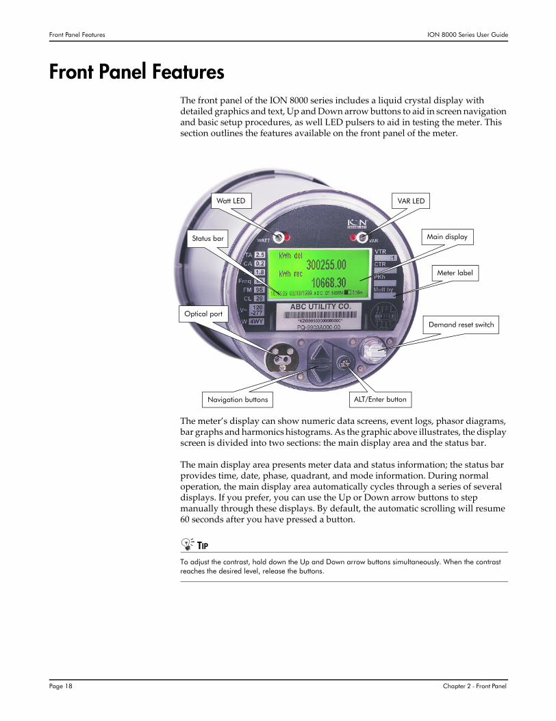
Front Panel FeaturesThe front panel of the ION 8000 series includes a liquid crystal display with detailed graphics and text, Up and Down arrow buttons to aid in screen navigation and basic setup procedures, as well LED pulsers to aid in testing the meter. This section outlines the features available on the front panel of the meter.
The meter’s display can show numeric data screens, event logs, phasor diagrams, bar graphs and harmonics histograms. As the graphic above illustrates, the display screen is divided into two sections: the main display area and the status bar.
The main display area presents meter data and status information; the status bar provides time, date, phase, quadrant, and mode information. During normal operation, the main display area automatically cycles through a series of several displays. If you prefer, you can use the Up or Down arrow buttons to step manually through these displays. By default, the automatic scrolling will resume 60 seconds after you have pressed a button.
TIP
To adjust the contrast, hold down the Up and Down arrow buttons simultaneously. When the contrast reaches the desired level, release the buttons.
Optical port
VAR LED
Status bar
Demand reset switch
Watt LED
Navigation buttons ALT/Enter button
Meter label
Main display
ION 8000 Series User Guide Front Panel Features
Chapter 2 - Front Panel Page 19
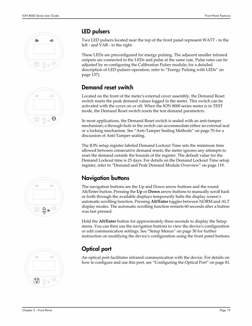
LED pulsersTwo LED pulsers located near the top of the front panel represent WATT - to the left - and VAR - to the right.
These LEDs are preconfigured for energy pulsing. The adjacent smaller infrared outputs are connected to the LEDs and pulse at the same rate. Pulse rates can be adjusted by re-configuring the Calibration Pulser module; for a detailed description of LED pulsers operation, refer to “Energy Pulsing with LEDs” on page 137).
Demand reset switchLocated on the front of the meter's external cover assembly, the Demand Reset switch resets the peak demand values logged in the meter. This switch can be activated with the cover on or off. When the ION 8000 series meter is in TEST mode, the Demand Reset switch resets the test demand parameters.
In most applications, the Demand Reset switch is sealed with an anti-tamper mechanism; a through-hole in the switch can accommodate either an external seal or a locking mechanism. See “Anti-Tamper Sealing Methods” on page 70 for a discussion of Anti-Tamper sealing.
The ION setup register labeled Demand Lockout Time sets the minimum time allowed between consecutive demand resets; the meter ignores any attempts to reset the demand outside the bounds of the register. The default value for the Demand Lockout time is 25 days. For details on the Demand Lockout Time setup register, refer to “Demand and Peak Demand Module Overview” on page 119.
Navigation buttonsThe navigation buttons are the Up and Down arrow buttons and the round Alt/Enter button. Pressing the Up or Down arrow buttons to manually scroll back or forth through the available displays temporarily halts the display screen’s automatic scrolling function. Pressing Alt/Enter toggles between NORM and ALT display modes. The automatic scrolling function restarts 60 seconds after a button was last pressed.
Hold the Alt/Enter button for approximately three seconds to display the Setup menu. You can then use the navigation buttons to view the device's configuration or edit communication settings. See “Setup Menus” on page 30 for further instruction on modifying the device's configuration using the front panel buttons.
Optical portAn optical port facilitates infrared communication with the device. For details on how to configure and use this port, see “Configuring the Optical Port” on page 81.
Front Panel Features ION 8000 Series User Guide
Page 20 Chapter 2 - Front Panel
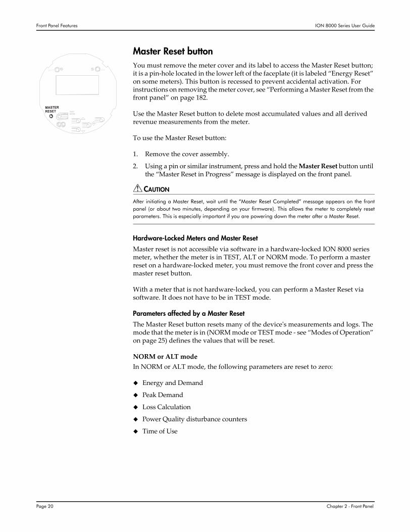
Master Reset buttonYou must remove the meter cover and its label to access the Master Reset button; it is a pin-hole located in the lower left of the faceplate (it is labeled “Energy Reset” on some meters). This button is recessed to prevent accidental activation. For instructions on removing the meter cover, see “Performing a Master Reset from the front panel” on page 182.
Use the Master Reset button to delete most accumulated values and all derived revenue measurements from the meter.
To use the Master Reset button:
1. Remove the cover assembly.
2. Using a pin or similar instrument, press and hold the Master Reset button until the “Master Reset in Progress” message is displayed on the front panel.
CAUTION
After initiating a Master Reset, wait until the “Master Reset Completed” message appears on the frontpanel (or about two minutes, depending on your firmware). This allows the meter to completely resetparameters. This is especially important if you are powering down the meter after a Master Reset.
Hardware-Locked Meters and Master Reset
Master reset is not accessible via software in a hardware-locked ION 8000 series meter, whether the meter is in TEST, ALT or NORM mode. To perform a master reset on a hardware-locked meter, you must remove the front cover and press the master reset button.
With a meter that is not hardware-locked, you can perform a Master Reset via software. It does not have to be in TEST mode.
Parameters affected by a Master Reset
The Master Reset button resets many of the device's measurements and logs. The mode that the meter is in (NORM mode or TEST mode - see “Modes of Operation” on page 25) defines the values that will be reset.
NORM or ALT modeIn NORM or ALT mode, the following parameters are reset to zero:
Energy and Demand
Peak Demand
Loss Calculation
Power Quality disturbance counters
Time of Use
VAR
MASTERRESET
WATT
TEST
MODE
ION 8000 Series User Guide Front Panel Features
Chapter 2 - Front Panel Page 21
The following are cleared:
Event Log
All Data Recorders
All Waveform Recorders
TEST modeAll TEST mode Energy and Demand measurements are set to zero.
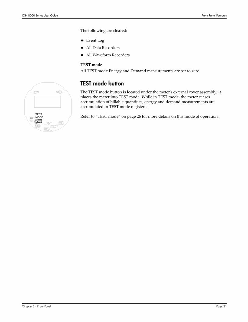
TEST mode buttonThe TEST mode button is located under the meter's external cover assembly; it places the meter into TEST mode. While in TEST mode, the meter ceases accumulation of billable quantities; energy and demand measurements are accumulated in TEST mode registers.
Refer to “TEST mode” on page 26 for more details on this mode of operation.
VAR
ENERGYENERGY
RESET
WATT
TEST
MODE
Display Screen Types ION 8000 Series User Guide
Page 22 Chapter 2 - Front Panel
Display Screen TypesThe front panel displays measurements, configured settings and configuration data in a variety of forms. The types of display screens are described below. For information on customizing the display on your meter, see “Configuring Front Panel Displays” on page 163.
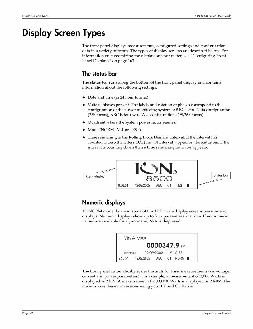
The status barThe status bar runs along the bottom of the front panel display and contains information about the following settings:
Date and time (in 24 hour format).
Voltage phases present. The labels and rotation of phases correspond to the configuration of the power monitoring system. AB BC is for Delta configuration (35S forms), ABC is four wire Wye configurations (9S/36S forms).
Quadrant where the system power factor resides.
Mode (NORM, ALT or TEST).
Time remaining in the Rolling Block Demand interval. If the interval has counted to zero the letters EOI (End Of Interval) appear on the status bar. If the interval is counting down then a time remaining indicator appears.
Numeric displaysAll NORM mode data and some of the ALT mode display screens use numeric displays. Numeric displays show up to four parameters at a time. If no numeric values are available for a parameter, N/A is displayed.
The front panel automatically scales the units for basic measurements (i.e. voltage, current and power parameters). For example, a measurement of 2,000 Watts is displayed as 2 kW. A measurement of 2,000,000 Watts is displayed as 2 MW. The meter makes these conversions using your PT and CT Ratios.
Status barMain display
ION 8000 Series User Guide Display Screen Types
Chapter 2 - Front Panel Page 23
The meter only performs these automatic units if the measurement is derived solely from the Power Meter module’s output.
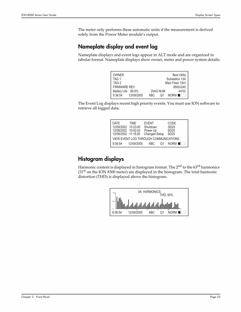
Nameplate display and event logNameplate displays and event logs appear in ALT mode and are organized in tabular format. Nameplate displays show owner, meter and power system details:
The Event Log displays recent high priority events. You must use ION software to retrieve all logged data:
Histogram displaysHarmonic content is displayed in histogram format. The 2nd to the 63rd harmonics (31st on the ION 8300 meter) are displayed in the histogram. The total harmonic distortion (THD) is displayed above the histogram.
Display Screen Types ION 8000 Series User Guide
Page 24 Chapter 2 - Front Panel
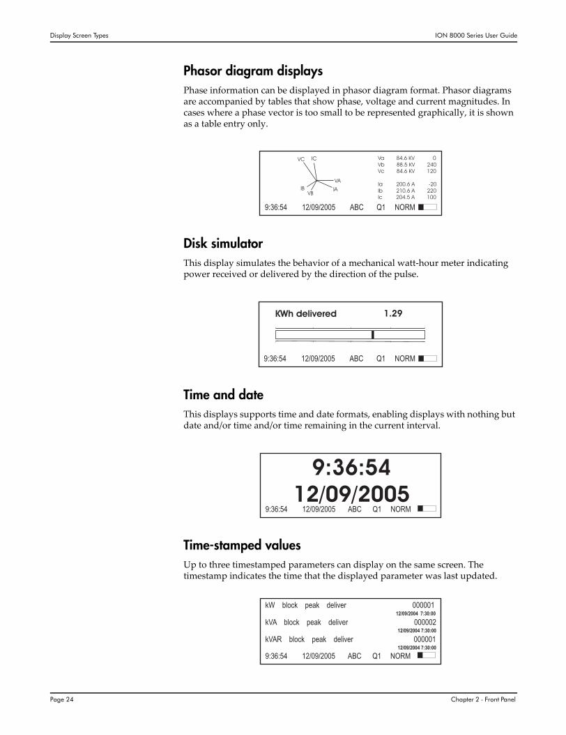
Phasor diagram displaysPhase information can be displayed in phasor diagram format. Phasor diagrams are accompanied by tables that show phase, voltage and current magnitudes. In cases where a phase vector is too small to be represented graphically, it is shown as a table entry only.
Disk simulatorThis display simulates the behavior of a mechanical watt-hour meter indicating power received or delivered by the direction of the pulse.
Time and dateThis displays supports time and date formats, enabling displays with nothing but date and/or time and/or time remaining in the current interval.
Time-stamped valuesUp to three timestamped parameters can display on the same screen. The timestamp indicates the time that the displayed parameter was last updated.
ION 8000 Series User Guide Modes of Operation
Chapter 2 - Front Panel Page 25
Modes of OperationThe ION 8000 series has three modes of operation: NORM, ALT and TEST. Both NORM and ALT are display modes, providing various power system data and meter properties screens. TEST mode is used to perform diagnostics and verify the meter’s calibration and function.
NOTE
If your meter has the optional hardware lock, you must remove the meter’s cover to put it into TEST mode.Refer to “Meter Security Features” on page 50 for more information.
Basic operation (NORM mode)The ION 8000 series meter defaults to NORM mode when powered up, and remains in this mode until you manually switch to ALT or TEST.
NOTE
You can customize NORM mode display screens and alter the front panel’s scrolling characteristics byediting the configuration of the meter’s Display and Scroll modules – refer to “Display Setup Menu” onpage 35 for more details.
If you have a meter without the hardware lock, all of the settings available in the panel Setup menu can be changed while the meter is in NORM mode, provided you have the correct password. If you have a hardware-locked meter, only the basic communications parameters in the COM Setup menu can be changed in NORM mode. (You must enter TEST mode to change other meter parameters on the hardware-locked meter — refer to “Additional Revenue Metering Security” on page 69 for more details.)
ALT modeALT mode provides scrolling display screens that show power system data, billing information (including extensive Time of Use data) and meter properties such as Nameplate information.
ALT mode screens are described in “ALT mode default display screens” on page 168.
Switching to ALT mode
Press the Alt/Enter button to switch to ALT mode. Press the Alt/Enter button again to switch back to NORM mode at any time. If no buttons are pressed, the meter automatically reverts to NORM mode after five minutes. As with any mode, pressing any button temporarily suspends display screen scrolling, allowing you to press the Up or Down arrow buttons to manually browse the available screens.
Modes of Operation ION 8000 Series User Guide
Page 26 Chapter 2 - Front Panel
TEST modeTEST mode is typically used for verifying meter calibration and function. The meter is usually reading data from a test power supply while these functions are performed.
All of the billing quantities that are recorded when the meter is in NORM and ALT mode will stop accumulating when the meter is switched to TEST mode — the data is sent to special TEST mode registers instead. The values accumulated in these test registers are displayed on the front panel (and in Vista software).
The regular NORM/ALT mode billing registers are unaffected while the meter is in TEST mode; accumulation of this data continues as soon as you exit TEST mode. All test registers are reset to zero when you exit TEST mode.
For detailed information on TEST mode, see “Switching to TEST Mode” on page 175.
NOTE
The meter will always return to NORM mode when you exit TEST mode, even if you entered TEST modefrom ALT mode.
ION 8000 Series User Guide Configuring the Meter with the Front Panel
Chapter 2 - Front Panel Page 27
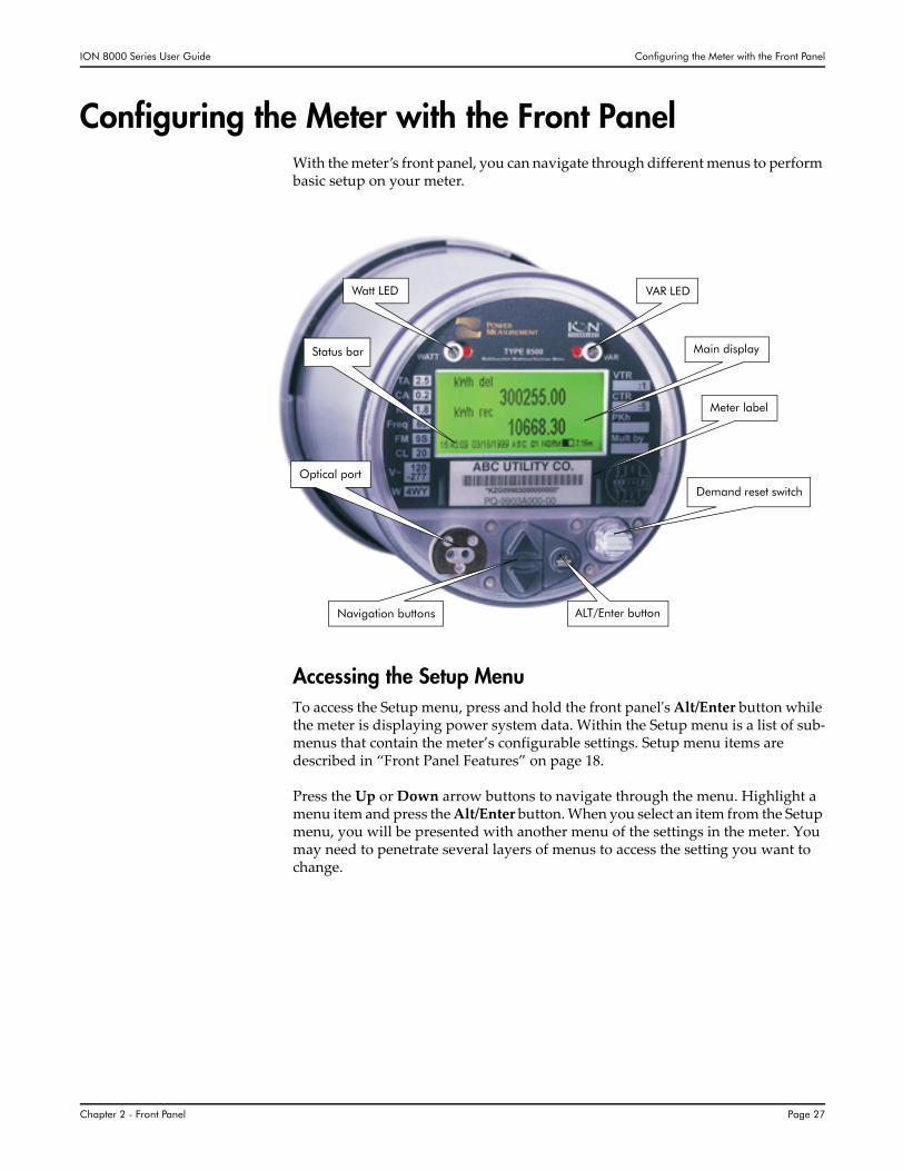
Configuring the Meter with the Front PanelWith the meter’s front panel, you can navigate through different menus to perform basic setup on your meter.
Accessing the Setup MenuTo access the Setup menu, press and hold the front panel's Alt/Enter button while the meter is displaying power system data. Within the Setup menu is a list of sub-menus that contain the meter’s configurable settings. Setup menu items are described in “Front Panel Features” on page 18.
Press the Up or Down arrow buttons to navigate through the menu. Highlight a menu item and press the Alt/Enter button. When you select an item from the Setup menu, you will be presented with another menu of the settings in the meter. You may need to penetrate several layers of menus to access the setting you want to change.
Optical port
VAR LED
Status bar
Demand reset switch
Watt LED
Navigation buttons ALT/Enter button
Meter label
Main display
Configuring the Meter with the Front Panel ION 8000 Series User Guide
Page 28 Chapter 2 - Front Panel
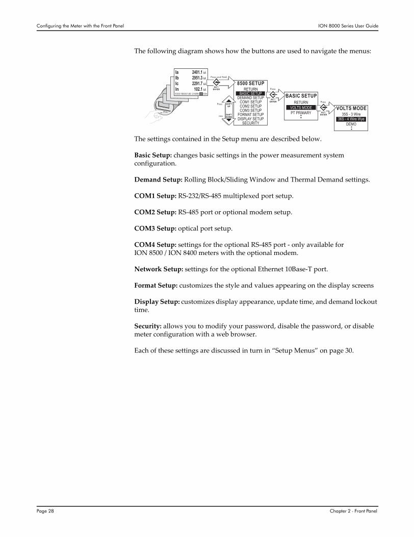
The following diagram shows how the buttons are used to navigate the menus:
The settings contained in the Setup menu are described below.
Basic Setup: changes basic settings in the power measurement system configuration.
Demand Setup: Rolling Block/Sliding Window and Thermal Demand settings.
COM1 Setup: RS-232/RS-485 multiplexed port setup.
COM2 Setup: RS-485 port or optional modem setup.
COM3 Setup: optical port setup.
COM4 Setup: settings for the optional RS-485 port - only available for ION 8500 / ION 8400 meters with the optional modem.
Network Setup: settings for the optional Ethernet 10Base-T port.
Format Setup: customizes the style and values appearing on the display screens
Display Setup: customizes display appearance, update time, and demand lockout time.
Security: allows you to modify your password, disable the password, or disable meter configuration with a web browser.
Each of these settings are discussed in turn in “Setup Menus” on page 30.
ION 8000 Series User Guide Configuring the Meter with the Front Panel
Chapter 2 - Front Panel Page 29
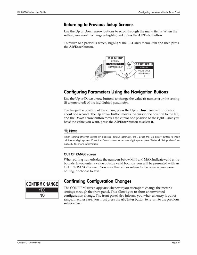
Returning to Previous Setup ScreensUse the Up or Down arrow buttons to scroll through the menu items. When the setting you want to change is highlighted, press the Alt/Enter button.
To return to a previous screen, highlight the RETURN menu item and then press the Alt/Enter button.
Configuring Parameters Using the Navigation ButtonsUse the Up or Down arrow buttons to change the value (if numeric) or the setting (if enumerated) of the highlighted parameter.
To change the position of the cursor, press the Up or Down arrow buttons for about one second. The Up arrow button moves the cursor one position to the left, and the Down arrow button moves the cursor one position to the right. Once you have the value you want, press the Alt/Enter button to select it.
NOTE
When setting Ethernet values (IP address, default gateway, etc.), press the Up arrow button to insertadditional digit spaces. Press the Down arrow to remove digit spaces (see “Network Setup Menu” onpage 33 for more information).
OUT OF RANGE screen
When editing numeric data the numbers below MIN and MAX indicate valid entry bounds. If you enter a value outside valid bounds, you will be presented with an OUT OF RANGE screen. You may then either return to the register you were editing, or choose to exit.
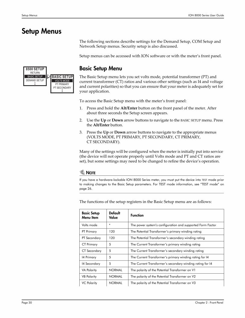
Confirming Configuration ChangesThe CONFIRM screen appears whenever you attempt to change the meter’s settings through the front panel. This allows you to abort an unwanted configuration change. The front panel also informs you when an entry is out of range. In either case, you must press the Alt/Enter button to return to the previous setup screen.
DEMAND SETUP
RETURN
8500 SETUP
BASIC SETUPBASIC SETUP
PT PRIMARY
VOLTS MODE
RETURN
CONFIRM CHANGE
NO
YES
Setup Menus ION 8000 Series User Guide
Page 30 Chapter 2 - Front Panel
Setup MenusThe following sections describe settings for the Demand Setup, COM Setup and Network Setup menus. Security setup is also discussed.
Setup menus can be accessed with ION software or with the meter’s front panel.
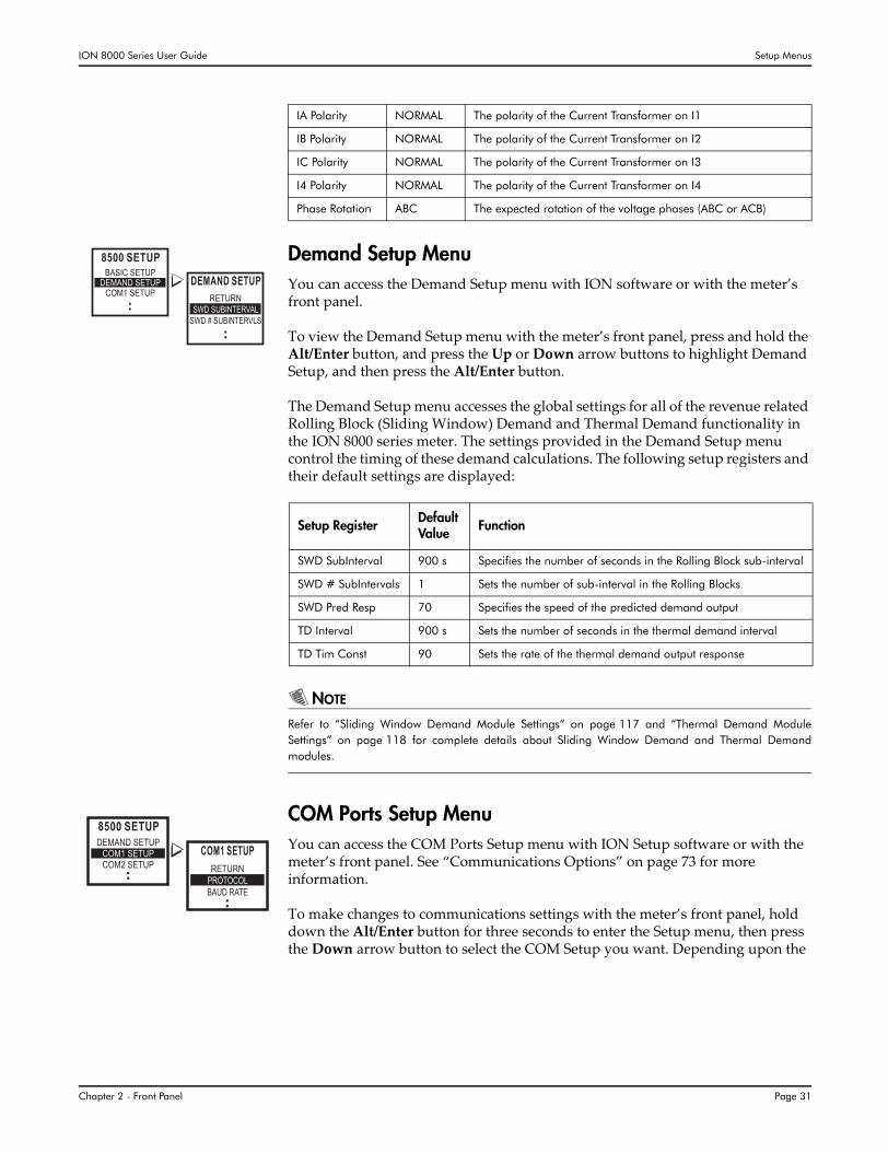
Basic Setup MenuThe Basic Setup menu lets you set volts mode, potential transformer (PT) and current transformer (CT) ratios and various other settings (such as I4 and voltage and current polarities) so that you can ensure that your meter is adequately set for your application.
To access the Basic Setup menu with the meter’s front panel:
1. Press and hold the Alt/Enter button on the front panel of the meter. After about three seconds the Setup screen appears.
2. Use the Up or Down arrow buttons to navigate to the BASIC SETUP menu. Press the Alt/Enter button.
3. Press the Up or Down arrow buttons to navigate to the appropriate menus (VOLTS MODE, PT PRIMARY, PT SECONDARY, CT PRIMARY, CT SECONDARY).
Many of the settings will be configured when the meter is initially put into service (the device will not operate properly until Volts mode and PT and CT ratios are set), but some settings may need to be changed to refine the device’s operation.
NOTE
If you have a hardware-lockable ION 8000 Series meter, you must put the device into TEST mode priorto making changes to the Basic Setup parameters. For TEST mode information, see “TEST mode” onpage 26.
The functions of the setup registers in the Basic Setup menu are as follows:
Basic Setup Menu Item
Default Value Function
Volts mode * The power system’s configuration and supported Form Factor
PT Primary 120 The Potential Transformer’s primary winding rating
PT Secondary 120 The Potential Transformer’s secondary winding rating
CT Primary 5 The Current Transformer’s primary winding rating
CT Secondary 5 The Current Transformer’s secondary winding rating
I4 Primary 5 The Current Transformer’s primary winding rating for I4
I4 Secondary 5 The Current Transformer’s secondary winding rating for I4
VA Polarity NORMAL The polarity of the Potential Transformer on V1
VB Polarity NORMAL The polarity of the Potential Transformer on V2
VC Polarity NORMAL The polarity of the Potential Transformer on V3
DEMAND SETUP
PT SECONDARY
RETURN
8500 SETUP
BASIC SETUPBASIC SETUP
PT PRIMARY
VOLTS MODE
ION 8000 Series User Guide Setup Menus
Chapter 2 - Front Panel Page 31
Demand Setup MenuYou can access the Demand Setup menu with ION software or with the meter’s front panel.
To view the Demand Setup menu with the meter’s front panel, press and hold the Alt/Enter button, and press the Up or Down arrow buttons to highlight Demand Setup, and then press the Alt/Enter button.
The Demand Setup menu accesses the global settings for all of the revenue related Rolling Block (Sliding Window) Demand and Thermal Demand functionality in the ION 8000 series meter. The settings provided in the Demand Setup menu control the timing of these demand calculations. The following setup registers and their default settings are displayed:
NOTE
Refer to “Sliding Window Demand Module Settings” on page 117 and “Thermal Demand ModuleSettings” on page 118 for complete details about Sliding Window Demand and Thermal Demandmodules.
COM Ports Setup MenuYou can access the COM Ports Setup menu with ION Setup software or with the meter’s front panel. See “Communications Options” on page 73 for more information.
To make changes to communications settings with the meter’s front panel, hold down the Alt/Enter button for three seconds to enter the Setup menu, then press the Down arrow button to select the COM Setup you want. Depending upon the
IA Polarity NORMAL The polarity of the Current Transformer on I1
IB Polarity NORMAL The polarity of the Current Transformer on I2
IC Polarity NORMAL The polarity of the Current Transformer on I3
I4 Polarity NORMAL The polarity of the Current Transformer on I4
Phase Rotation ABC The expected rotation of the voltage phases (ABC or ACB)
Setup Register Default Value Function
SWD SubInterval 900 s Specifies the number of seconds in the Rolling Block sub-interval
SWD # SubIntervals 1 Sets the number of sub-interval in the Rolling Blocks
SWD Pred Resp 70 Specifies the speed of the predicted demand output
TD Interval 900 s Sets the number of seconds in the thermal demand interval
TD Tim Const 90 Sets the rate of the thermal demand output response
COM1 SETUP
8500 SETUP
DEMAND SETUPBASIC SETUP
SWD # SUBINTERVLS
RETURN
SWD SUBINTERVAL
DEMAND SETUP
COM2 SETUP
8500 SETUP
COM1 SETUP
BAUD RATE
RETURN
PROTOCOL
DEMAND SETUP
COM1 SETUP
Setup Menus ION 8000 Series User Guide
Page 32 Chapter 2 - Front Panel
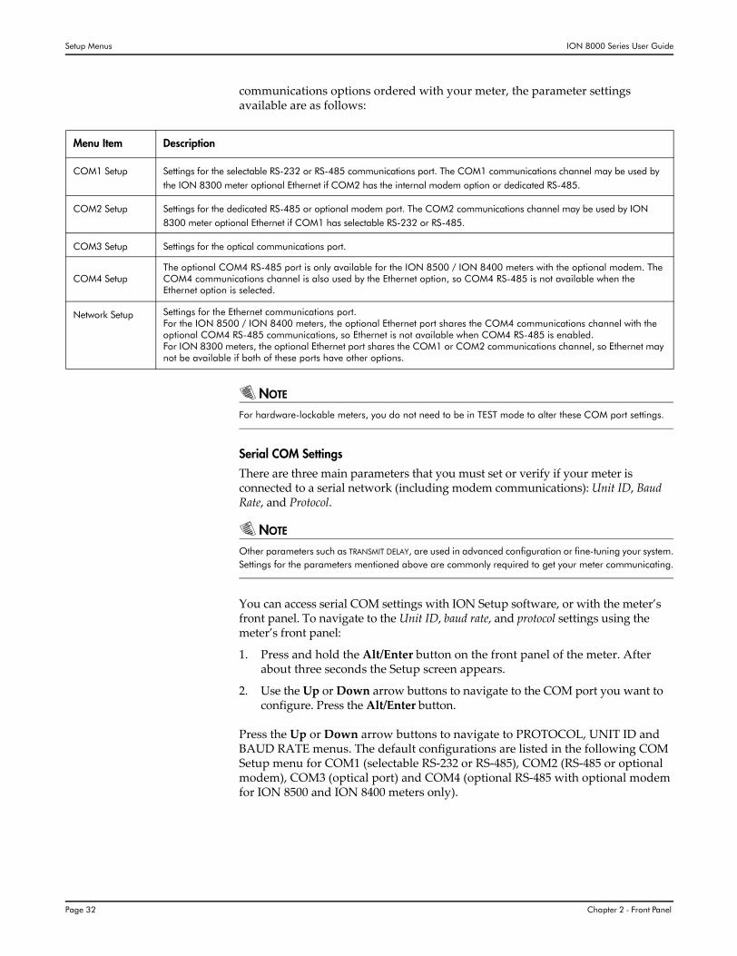
communications options ordered with your meter, the parameter settings available are as follows:
NOTE
For hardware-lockable meters, you do not need to be in TEST mode to alter these COM port settings.
Serial COM Settings
There are three main parameters that you must set or verify if your meter is connected to a serial network (including modem communications): Unit ID, Baud Rate, and Protocol.
NOTE
Other parameters such as TRANSMIT DELAY, are used in advanced configuration or fine-tuning your system.Settings for the parameters mentioned above are commonly required to get your meter communicating.
You can access serial COM settings with ION Setup software, or with the meter’s front panel. To navigate to the Unit ID, baud rate, and protocol settings using the meter’s front panel:
1. Press and hold the Alt/Enter button on the front panel of the meter. After about three seconds the Setup screen appears.
2. Use the Up or Down arrow buttons to navigate to the COM port you want to configure. Press the Alt/Enter button.
Press the Up or Down arrow buttons to navigate to PROTOCOL, UNIT ID and BAUD RATE menus. The default configurations are listed in the following COM Setup menu for COM1 (selectable RS-232 or RS-485), COM2 (RS-485 or optional modem), COM3 (optical port) and COM4 (optional RS-485 with optional modem for ION 8500 and ION 8400 meters only).
Menu Item Description
COM1 Setup Settings for the selectable RS-232 or RS-485 communications port. The COM1 communications channel may be used by the ION 8300 meter optional Ethernet if COM2 has the internal modem option or dedicated RS-485.
COM2 Setup Settings for the dedicated RS-485 or optional modem port. The COM2 communications channel may be used by ION 8300 meter optional Ethernet if COM1 has selectable RS-232 or RS-485.
COM3 Setup Settings for the optical communications port.
COM4 SetupThe optional COM4 RS-485 port is only available for the ION 8500 / ION 8400 meters with the optional modem. The COM4 communications channel is also used by the Ethernet option, so COM4 RS-485 is not available when the Ethernet option is selected.
Network Setup Settings for the Ethernet communications port. For the ION 8500 / ION 8400 meters, the optional Ethernet port shares the COM4 communications channel with the optional COM4 RS-485 communications, so Ethernet is not available when COM4 RS-485 is enabled. For ION 8300 meters, the optional Ethernet port shares the COM1 or COM2 communications channel, so Ethernet may not be available if both of these ports have other options.
ION 8000 Series User Guide Setup Menus
Chapter 2 - Front Panel Page 33
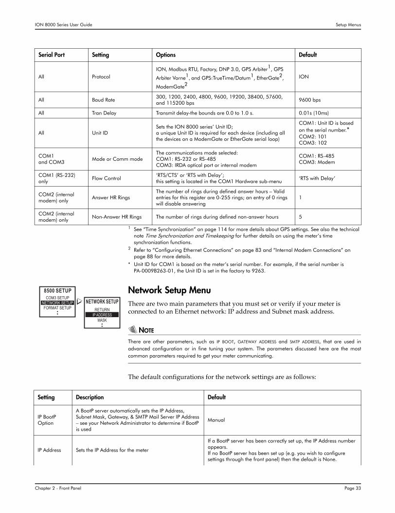
1 See “Time Synchronization” on page 114 for more details about GPS settings. See also the technical note Time Synchronization and Timekeeping for further details on using the meter’s time synchronization functions.
2 Refer to “Configuring Ethernet Connections” on page 83 and “Internal Modem Connections” on page 88 for more details.
* Unit ID for COM1 is based on the meter’s serial number. For example, if the serial number is PA-0009B263-01, the Unit ID is set in the factory to 9263.
Network Setup MenuThere are two main parameters that you must set or verify if your meter is connected to an Ethernet network: IP address and Subnet mask address.
NOTE
There are other parameters, such as IP BOOT, GATEWAY ADDRESS and SMTP ADDRESS, that are used inadvanced configuration or in fine tuning your system. The parameters discussed here are the mostcommon parameters required to get your meter communicating.
The default configurations for the network settings are as follows:
Serial Port Setting Options Default
All ProtocolION, Modbus RTU, Factory, DNP 3.0, GPS Arbiter1, GPS
Arbiter Vorne1, and GPS:TrueTime/Datum1, EtherGate2,
ModemGate2ION
All Baud Rate 300, 1200, 2400, 4800, 9600, 19200, 38400, 57600,and 115200 bps 9600 bps
All Tran Delay Transmit delay-the bounds are 0.0 to 1.0 s. 0.01s (10ms)
All Unit IDSets the ION 8000 series’ Unit ID;a unique Unit ID is required for each device (including all the devices on a ModemGate or EtherGate serial loop)
COM1: Unit ID is based on the serial number.*COM2: 101COM3: 102
COM1and COM3 Mode or Comm mode
The communications mode selected:COM1: RS-232 or RS-485COM3: IRDA optical port or internal modem
COM1: RS-485COM3: Modem
COM1 (RS-232) only Flow Control
‘RTS/CTS’ or ‘RTS with Delay’;this setting is located in the COM1 Hardware sub-menu ‘RTS with Delay’
COM2 (internal modem) only
Answer HR RingsThe number of rings during defined answer hours – Valid entries for this register are 0-255 rings; an entry of 0 rings will disable answering
1
COM2 (internal modem) only
Non-Answer HR Rings The number of rings during defined non-answer hours 5
FORMAT SETUP
8500 SETUP
NETWORK SETUP
MASK
RETURN
IP ADDRESS
COM3 SETUP
NETWORK SETUP
Setting Description Default
IP BootP Option
A BootP server automatically sets the IP Address, Subnet Mask, Gateway, & SMTP Mail Server IP Address– see your Network Administrator to determine if BootP is used
Manual
IP Address Sets the IP Address for the meter
If a BootP server has been correctly set up, the IP Address number appears.If no BootP server has been set up (e.g. you wish to configure settings through the front panel) then the default is None.
Setup Menus ION 8000 Series User Guide
Page 34 Chapter 2 - Front Panel
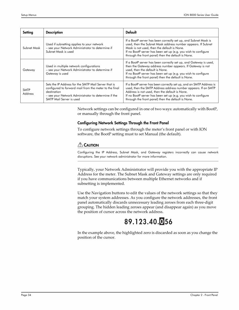
Network settings can be configured in one of two ways: automatically with BootP, or manually through the front panel.
Configuring Network Settings Through the Front Panel
To configure network settings through the meter’s front panel or with ION software, the BootP setting must to set Manual (the default).
CAUTION
Configuring the IP Address, Subnet Mask, and Gateway registers incorrectly can cause networkdisruptions. See your network administrator for more information.
Typically, your Network Administrator will provide you with the appropriate IP Address for the meter. The Subnet Mask and Gateway settings are only required if you have communications between multiple Ethernet networks and if subnetting is implemented.
Use the Navigation buttons to edit the values of the network settings so that they match your system addresses. As you configure the network addresses, the front panel automatically discards unnecessary leading zeroes from each three-digit grouping. The hidden leading zeroes appear (and disappear again) as you move the position of cursor across the network address.
In the example above, the highlighted zero is discarded as soon as you change the position of the cursor.
Subnet MaskUsed if subnetting applies to your network– see your Network Administrator to determine if Subnet Mask is used
If a BootP server has been correctly set up, and Subnet Mask is used, then the Subnet Mask address number appears. If Subnet Mask is not used, then the default is None.If no BootP server has been set up (e.g. you wish to configure through the front panel) then the default is None.
GatewayUsed in multiple network configurations – see your Network Administrator to determine if Gateway is used
If a BootP server has been correctly set up, and Gateway is used, then the Gateway address number appears. If Gateway is not used, then the default is None.If no BootP server has been set up (e.g. you wish to configure through the front panel) then the default is None.
SMTP Address
Sets the IP Address for the SMTP Mail Server that is configured to forward mail from the meter to the final destination– see your Network Administrator to determine if the SMTP Mail Server is used
If a BootP server has been correctly set up, and an SMTP Address is used, then the SMTP Address address number appears. If an SMTP Address is not used, then the default is None.If no BootP server has been set up (e.g. you wish to configure through the front panel) then the default is None.
Setting Description Default
89.123.40. 560
ION 8000 Series User Guide Setup Menus
Chapter 2 - Front Panel Page 35
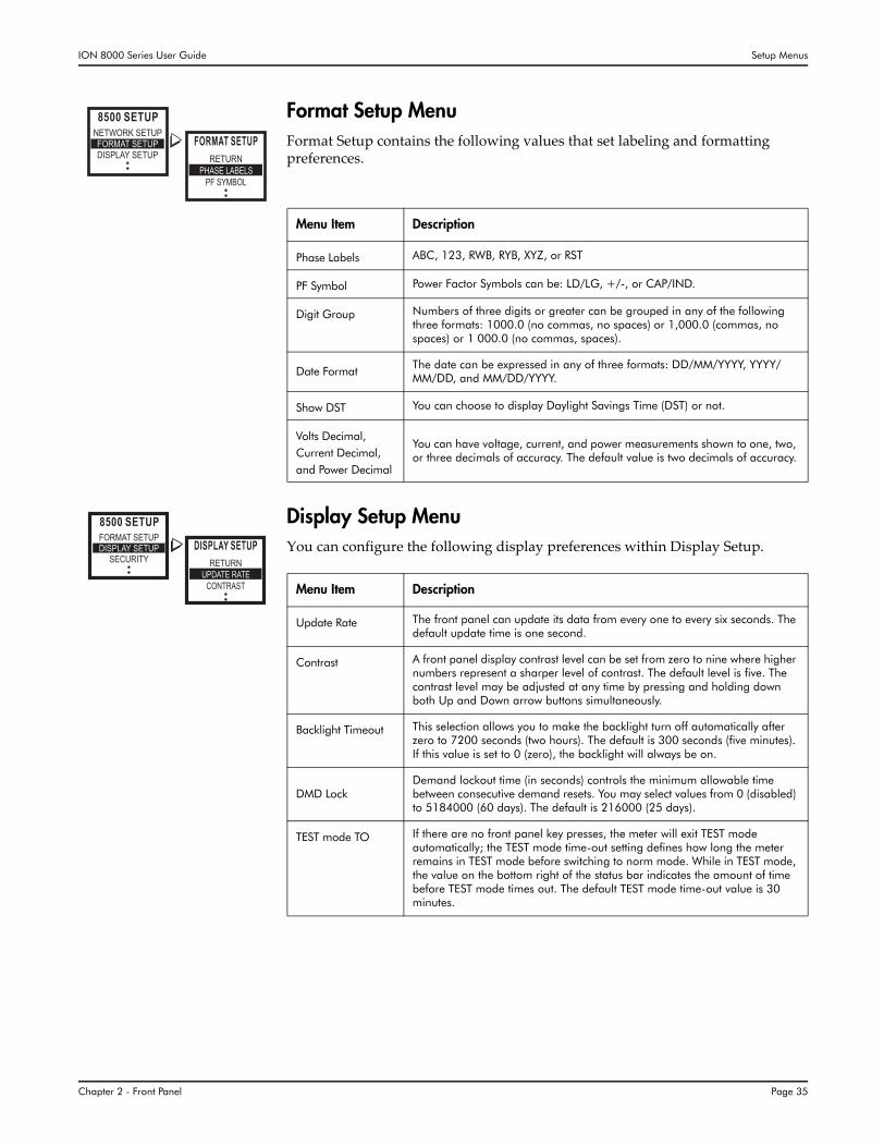
Format Setup MenuFormat Setup contains the following values that set labeling and formatting preferences.
Display Setup MenuYou can configure the following display preferences within Display Setup.
Menu Item Description
Phase Labels ABC, 123, RWB, RYB, XYZ, or RST
PF Symbol Power Factor Symbols can be: LD/LG, +/-, or CAP/IND.
Digit Group Numbers of three digits or greater can be grouped in any of the following three formats: 1000.0 (no commas, no spaces) or 1,000.0 (commas, no spaces) or 1 000.0 (no commas, spaces).
Date Format The date can be expressed in any of three formats: DD/MM/YYYY, YYYY/MM/DD, and MM/DD/YYYY.
Show DST You can choose to display Daylight Savings Time (DST) or not.
Volts Decimal, Current Decimal, and Power Decimal
You can have voltage, current, and power measurements shown to one, two, or three decimals of accuracy. The default value is two decimals of accuracy.
Menu Item Description
Update Rate The front panel can update its data from every one to every six seconds. The default update time is one second.
Contrast A front panel display contrast level can be set from zero to nine where higher numbers represent a sharper level of contrast. The default level is five. The contrast level may be adjusted at any time by pressing and holding down both Up and Down arrow buttons simultaneously.
Backlight Timeout This selection allows you to make the backlight turn off automatically after zero to 7200 seconds (two hours). The default is 300 seconds (five minutes). If this value is set to 0 (zero), the backlight will always be on.
DMD LockDemand lockout time (in seconds) controls the minimum allowable time between consecutive demand resets. You may select values from 0 (disabled) to 5184000 (60 days). The default is 216000 (25 days).
TEST mode TO If there are no front panel key presses, the meter will exit TEST mode automatically; the TEST mode time-out setting defines how long the meter remains in TEST mode before switching to norm mode. While in TEST mode, the value on the bottom right of the status bar indicates the amount of time before TEST mode times out. The default TEST mode time-out value is 30 minutes.
DISPLAY SETUP
8500 SETUP
FORMAT SETUP
PF SYMBOL
RETURN
PHASE LABELS
NETWORK SETUP
FORMAT SETUP
SECURITY
8500 SETUP
DISPLAY SETUP
CONTRAST
RETURN
UPDATE RATE
FORMAT SETUP
DISPLAY SETUP
Setup Menus ION 8000 Series User Guide
Page 36 Chapter 2 - Front Panel
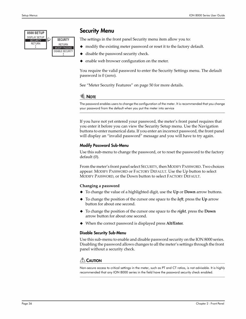
Security MenuThe settings in the front panel Security menu item allow you to:
modify the existing meter password or reset it to the factory default.
disable the password security check.
enable web browser configuration on the meter.
You require the valid password to enter the Security Settings menu. The default password is 0 (zero).
See “Meter Security Features” on page 50 for more details.
NOTE
The password enables users to change the configuration of the meter. It is recommended that you changeyour password from the default when you put the meter into service
If you have not yet entered your password, the meter’s front panel requires that you enter it before you can view the Security Setup menu. Use the Navigation buttons to enter numerical data. If you enter an incorrect password, the front panel will display an “invalid password” message and you will have to try again.
Modify Password Sub-Menu
Use this sub-menu to change the password, or to reset the password to the factory default (0).
From the meter’s front panel select SECURITY, then MODIFY PASSWORD. Two choices appear: MODIFY PASSWORD or FACTORY DEFAULT. Use the Up button to select MODIFY PASSWORD, or the Down button to select FACTORY DEFAULT.
Changing a passwordTo change the value of a highlighted digit, use the Up or Down arrow buttons.
To change the position of the cursor one space to the left, press the Up arrow button for about one second.
To change the position of the cursor one space to the right, press the Down arrow button for about one second.
When the correct password is displayed press Alt/Enter.
Disable Security Sub-Menu
Use this sub-menu to enable and disable password security on the ION 8000 series. Disabling the password allows changes to all the meter’s settings through the front panel without a security check.
CAUTION
Non-secure access to critical settings in the meter, such as PT and CT ratios, is not advisable. It is highlyrecommended that any ION 8000 series in the field have the password security check enabled.
RETURN
8500 SETUP
SECURITY
DISABLE SECURITY
RETURN
MODIFY PASSWD
DISPLAY SETUP
SECURITY

ION 8000 Series User Guide Setup Menus
Chapter 2 - Front Panel Page 37
When you re-enable password security, the password is reset to the factory default of 0 (zero). You should re-enter a custom password at this point.
Disabling the Password Security Check is necessary to write to the meter when it is a Modbus Slave device. Refer to “The Meter as Modbus Slave” on page 97 for details about configuring your ION 8000 series for third-party systems.
Web Config
Use this setting to enable/disable web browser configuration of the meter. See “Enabling and Disabling Web Config Access” on page 55 for more details.

Page 39
3 Templates and FirmwareYour meter comes installed with a pre-configured default template. This template contains various frameworks which provide all the power measuring and analyzing functionality of the meter. Templates and frameworks can be used immediately without any user configuration (“right out of the box”). They can also be customized, reconfigured, and pasted from one meter to another.
For more information on templates, frameworks and ION modules, see the ION Reference.
Your meter’s operating system is known as firmware. When newer firmware is available for your meter, simply upgrade to the latest version for all the added features and functionality.
In this chapter
Factory Information . . . . . . . . . . . . . . . . . . . . . . . . . . . . . . . . . . . . . . . . . 40Factory Module Settings ....................................................................................... 40How to TAG Your Meter ...................................................................................... 40
Restoring the Factory Configuration . . . . . . . . . . . . . . . . . . . . . . . . . . . . . . 41Using Designer ...................................................................................................... 41Using ION Setup ................................................................................................... 42
Upgrading Your Meter . . . . . . . . . . . . . . . . . . . . . . . . . . . . . . . . . . . . . . . . . . . . . . . . 43
Factory Information ION 8000 Series User Guide
Page 40 Chapter 3 - Templates and Firmware
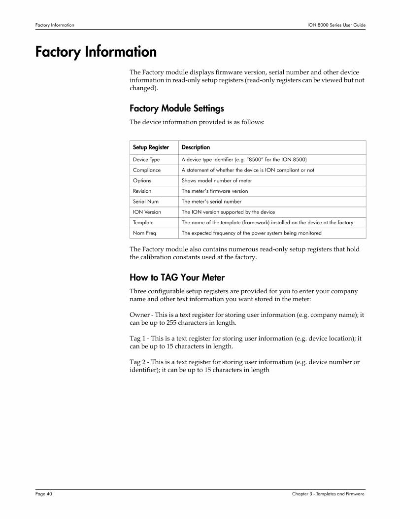
Factory InformationThe Factory module displays firmware version, serial number and other device information in read-only setup registers (read-only registers can be viewed but not changed).
Factory Module SettingsThe device information provided is as follows:
The Factory module also contains numerous read-only setup registers that hold the calibration constants used at the factory.
How to TAG Your MeterThree configurable setup registers are provided for you to enter your company name and other text information you want stored in the meter:
Owner - This is a text register for storing user information (e.g. company name); it can be up to 255 characters in length.
Tag 1 - This is a text register for storing user information (e.g. device location); it can be up to 15 characters in length.
Tag 2 - This is a text register for storing user information (e.g. device number or identifier); it can be up to 15 characters in length
Setup Register Description
Device Type A device type identifier (e.g. “8500” for the ION 8500)
Compliance A statement of whether the device is ION compliant or not
Options Shows model number of meter
Revision The meter’s firmware version
Serial Num The meter’s serial number
ION Version The ION version supported by the device
Template The name of the template (framework) installed on the device at the factory
Nom Freq The expected frequency of the power system being monitored
ION 8000 Series User Guide Restoring the Factory Configuration
Chapter 3 - Templates and Firmware Page 41
Restoring the Factory ConfigurationIf you have made changes to the default functionality and want to return to the factory configuration, you can re-initialize the factory configuration in the meter using ION software. The basic setup of the device can be retained, so the meter does not need to be taken out of service for a long period of time.
NOTE
If you restore the factory configuration, all custom features you have created are lost.
Using Designer1. Display the meter’s main Configuration screen in Designer.
2. Choose Select All from the Edit menu, then press Delete.
The confirmation dialog box appears explaining that some modules will not be deleted (core modules cannot be deleted — scroll down in the dialog to see which standard modules will be deleted).
3. Click OK on the confirmation dialog box.
After a brief wait the modules are deleted, and the main meter Configuration screen is blank except for the Frameworks folder in the Advanced Setup area. (The Frameworks folder contains the folder of Core modules which cannot be deleted.)
4. Choose Select All from the Edit menu to select the Frameworks folder. This selects all subfolders and modules within the folder.
5. In the Edit menu, choose Paste from Framework, then select the appropriate.fwn file from the folder \ION Enterprise\config\fmwk\nd\. Click OK.
The Factory module’s Default Template register tells you the filename for the default factory framework. (For details about framework files, contact Customer Service or visit the Support area of the Power Measurement web site.)
6. Click Open. The Paste Summary window appears.
7. Click on the first module, scroll down to the last module, hold the Shift key and click on the last module. This selects all of the modules.
8. While holding the Shift key, click on the check box to the left of the module name so you see a lock icon with a green check mark.
CAUTION
Persistent modules can be overwritten in Designer. When pasting a default framework onto a meter, uselock-paste on the Persistent modules, not free-paste. A list of Persistent modules is available fromCustomer Service.
9. Check “Maintain external inputs” and click OK on the confirmation dialog box.
A message appears indicating that Designer is pasting modules. All modules are selected when the paste is complete. Click anywhere in the background of the node diagram to deselect all of the modules.
Restoring the Factory Configuration ION 8000 Series User Guide
Page 42 Chapter 3 - Templates and Firmware
10. Click the Power Meter shortcut in the Basic Configuration area to select it. Once selected, click Reset in the Designer toolbar, or select Reset from the Edit menu. This reverts the Power Meter to the settings it had before you deleted any modules (retaining the basic setup you previously had).
11. Choose Send & Save from the File menu. The factory configuration is now restored and any custom functionality you created is removed.
NOTE
The time required to complete steps 3, 5, and 11 may vary depending on your connection and the meterconfiguration.
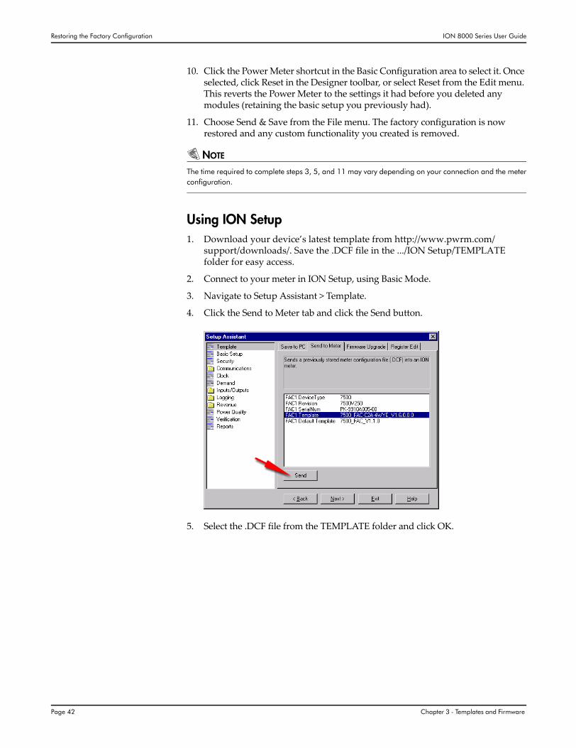
Using ION Setup1. Download your device’s latest template from http://www.pwrm.com/
support/downloads/. Save the .DCF file in the .../ION Setup/TEMPLATE folder for easy access.
2. Connect to your meter in ION Setup, using Basic Mode.
3. Navigate to Setup Assistant > Template.
4. Click the Send to Meter tab and click the Send button.
5. Select the .DCF file from the TEMPLATE folder and click OK.
ION 8000 Series User Guide Upgrading Your Meter
Chapter 3 - Templates and Firmware Page 43
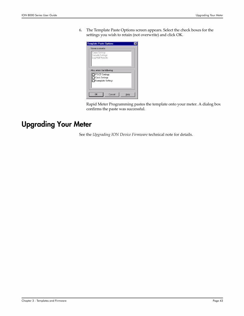
6. The Template Paste Options screen appears. Select the check boxes for the settings you wish to retain (not overwrite) and click OK.
Rapid Meter Programming pastes the template onto your meter. A dialog box confirms the paste was successful.
Upgrading Your MeterSee the Upgrading ION Device Firmware technical note for details.

Page 45
4 Basic SetupThis chapter explains how to perform basic meter setup via the front panel or via ION software.
In this chapter
Introduction . . . . . . . . . . . . . . . . . . . . . . . . . . . . . . . . . . . . . . . . . . . . . . . 46Configuring Basic Setup . . . . . . . . . . . . . . . . . . . . . . . . . . . . . . . . . . . . . . . . . . . . . . . 46
Using the Front Panel ........................................................................................... 46Using ION Setup ................................................................................................... 46Using Designer ...................................................................................................... 47
Power Meter Module Settings . . . . . . . . . . . . . . . . . . . . . . . . . . . . . . . . . . . . . . . . . . 48
Introduction ION 8000 Series User Guide
Page 46 Chapter 4 - Basic Setup
IntroductionBasic configuration of the meter is provided by the Power Meter module. The Power Meter module is the main connection between the power system measurements and all other ION modules in the device. This module reports the values for all voltage, current and power measurements. The Power Meter module’s setup registers describe details of the power system being monitored. Many of the Power Meter module’s setup registers are configured when the meter is initially put into service, although the device cannot operate properly until the Volts Mode and PT and CT ratios are set. Some registers may need to be changed to refine the device’s operation. See the ION Reference for more details on the Power Meter module.
Configuring Basic SetupUse the front panel or ION software to perform basic meter setup.
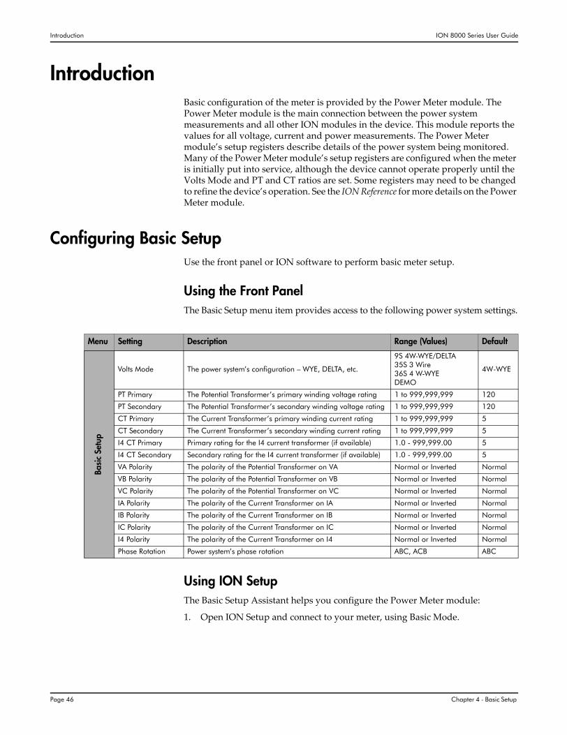
Using the Front PanelThe Basic Setup menu item provides access to the following power system settings.
Using ION SetupThe Basic Setup Assistant helps you configure the Power Meter module:
1. Open ION Setup and connect to your meter, using Basic Mode.
Menu Setting Description Range (Values) Default
Basi
c Se
tup
Volts Mode The power system’s configuration – WYE, DELTA, etc.
9S 4W-WYE/DELTA35S 3 Wire36S 4 W-WYEDEMO
4W-WYE
PT Primary The Potential Transformer’s primary winding voltage rating 1 to 999,999,999 120
PT Secondary The Potential Transformer’s secondary winding voltage rating 1 to 999,999,999 120
CT Primary The Current Transformer’s primary winding current rating 1 to 999,999,999 5
CT Secondary The Current Transformer’s secondary winding current rating 1 to 999,999,999 5
I4 CT Primary Primary rating for the I4 current transformer (if available) 1.0 - 999,999.00 5
I4 CT Secondary Secondary rating for the I4 current transformer (if available) 1.0 - 999,999.00 5
VA Polarity The polarity of the Potential Transformer on VA Normal or Inverted Normal
VB Polarity The polarity of the Potential Transformer on VB Normal or Inverted Normal
VC Polarity The polarity of the Potential Transformer on VC Normal or Inverted Normal
IA Polarity The polarity of the Current Transformer on IA Normal or Inverted Normal
IB Polarity The polarity of the Current Transformer on IB Normal or Inverted Normal
IC Polarity The polarity of the Current Transformer on IC Normal or Inverted Normal
I4 Polarity The polarity of the Current Transformer on I4 Normal or Inverted Normal
Phase Rotation Power system’s phase rotation ABC, ACB ABC
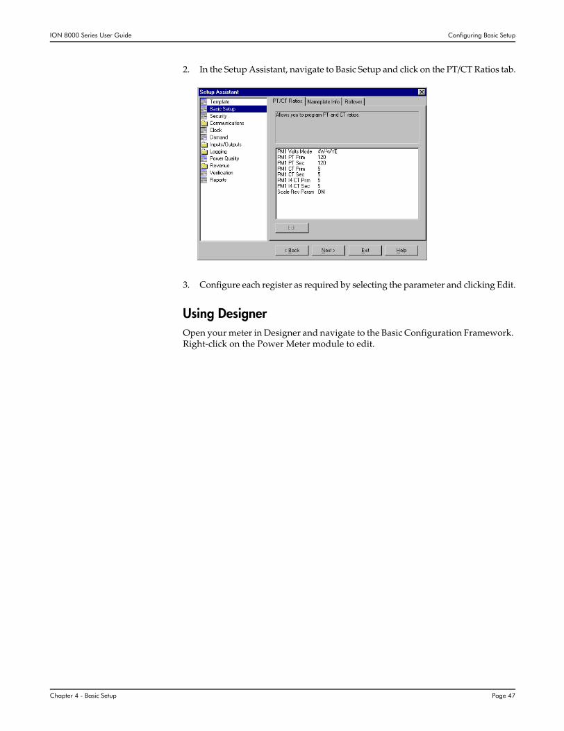
ION 8000 Series User Guide Configuring Basic Setup
Chapter 4 - Basic Setup Page 47
2. In the Setup Assistant, navigate to Basic Setup and click on the PT/CT Ratios tab.
3. Configure each register as required by selecting the parameter and clicking Edit.
Using DesignerOpen your meter in Designer and navigate to the Basic Configuration Framework. Right-click on the Power Meter module to edit.
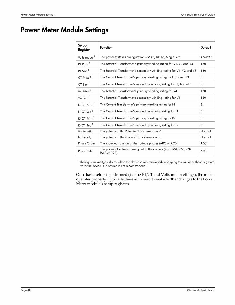
Power Meter Module Settings ION 8000 Series User Guide
Page 48 Chapter 4 - Basic Setup
Power Meter Module Settings
1 The registers are typically set when the device is commissioned. Changing the values of these registers while the device is in service is not recommended.
Once basic setup is performed (i.e. the PT/CT and Volts mode settings), the meter operates properly. Typically there is no need to make further changes to the Power Meter module’s setup registers.
Setup Register Function Default
Volts mode 1 The power system’s configuration – WYE, DELTA, Single, etc 4W-WYE
PT Prim 1 The Potential Transformer’s primary winding rating for V1, V2 and V3 120
PT Sec 1 The Potential Transformer’s secondary winding rating for V1, V2 and V3 120
CT Prim 1 The Current Transformer’s primary winding rating for I1, I2 and I3 5
CT Sec 1 The Current Transformer’s secondary winding rating for I1, I2 and I3 5
V4 Prim 1 The Potential Transformer’s primary winding rating for V4 120
V4 Sec 1 The Potential Transformer’s secondary winding rating for V4 120
I4 CT Prim 1 The Current Transformer’s primary winding rating for I4 5
I4 CT Sec 1 The Current Transformer’s secondary winding rating for I4 5
I5 CT Prim 1 The Current Transformer’s primary winding rating for I5 5
I5 CT Sec 1 The Current Transformer’s secondary winding rating for I5 5
Vn Polarity The polarity of the Potential Transformer on Vn Normal
In Polarity The polarity of the Current Transformer on In Normal
Phase Order The expected rotation of the voltage phases (ABC or ACB) ABC
Phase Lbls The phase label format assigned to the outputs (ABC, RST, XYZ, RYB, RWB or 123) ABC
Page 49
5 SecurityION 8000 series meters offer Standard and Advanced meter security. Standard security is enabled by default from the factory; procedures for changing these security settings using the front panel and ION software are detailed in this chapter. Advanced security, which allows up to 16 users, each with unique access privileges, is discussed as well. This chapter also details some security features available for revenue meters.
In this chapter
Meter Security Features . . . . . . . . . . . . . . . . . . . . . . . . . . . . . . . . . . . . . . . 50
Standard Meter Security . . . . . . . . . . . . . . . . . . . . . . . . . . . . . . . . . . . . . . 51Scenarios for Standard Security - Front Panel Security Enabled . . . . . . . . . . . . . 59
Advanced Meter Security . . . . . . . . . . . . . . . . . . . . . . . . . . . . . . . . . . . . . 62Device Security Access for ION Services . . . . . . . . . . . . . . . . . . . . . . . . . . . . . . . . . 65Scenarios for Advanced Security - Front Panel Security Enabled . . . . . . . . . . . . 67
Additional Revenue Metering Security . . . . . . . . . . . . . . . . . . . . . . . . . . . . 70
Anti-Tamper Sealing Methods . . . . . . . . . . . . . . . . . . . . . . . . . . . . . . . . . . 71
Meter Security Features ION 8000 Series User Guide
Page 50 Chapter 5 - Security
Meter Security FeaturesYour meter includes the following security features:
Standard meter security
Anytime you make configuration changes to your meter you must enter a password. See “Standard Meter Security” on page 51.
Advanced meter security
Available only on the ION 8000 series meter, this level of security allows configuration of up to 16 users, each with unique access rights to the meter. See the topic “Configuring Advanced Meter Security” on page 61.
Revenue meter security
Your revenue meter can be protected by anti-tamper sealing. See “Additional Revenue Metering Security” on page 69.
Software security
ION software security brings access-level security to the meter. With ION software, you can configure multiple users with different passwords and specify access rights. ION software security only applies to users who are accessing the meter via ION software.
For more information on ION software security, refer to the ION Security technical note.
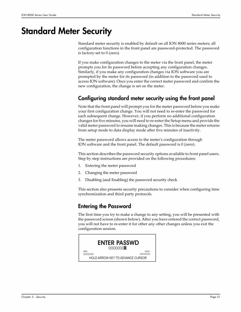
ION 8000 Series User Guide Standard Meter Security
Chapter 5 - Security Page 51
Standard Meter SecurityStandard meter security is enabled by default on all ION 8000 series meters; all configuration functions in the front panel are password-protected. The password is factory-set to 0 (zero).
If you make configuration changes to the meter via the front panel, the meter prompts you for its password before accepting any configuration changes. Similarly, if you make any configuration changes via ION software you are prompted by the meter for its password (in addition to the password used to access ION software). Once you enter the correct meter password and confirm the new configuration, the change is set on the meter.
Configuring standard meter security using the front panelNote that the front panel will prompt you for the meter password before you make your first configuration change. You will not need to re-enter the password for each subsequent change. However, if you perform no additional configuration changes for five minutes, you will need to re-enter the Setup menu and provide the valid meter password to resume making changes. This is because the meter returns from setup mode to data display mode after five minutes of inactivity.
The meter password allows access to the meter's configuration through ION software and the front panel. The default password is 0 (zero).
This section describes the password security options available to front panel users. Step by step instructions are provided on the following procedures:
1. Entering the meter password
2. Changing the meter password
3. Disabling (and Enabling) the password security check
This section also presents security precautions to consider when configuring time synchronization and third party protocols.
Entering the PasswordThe first time you try to make a change to any setting, you will be presented with the password screen (shown below). After you have entered the correct password, you will not have to re-enter it for other any other changes unless you exit the configuration session.
HOLD ARROW KEY TO ADVANCE CURSOR
ENTER PASSWD
MIN:
00000000
MAX:
99999999
00000000
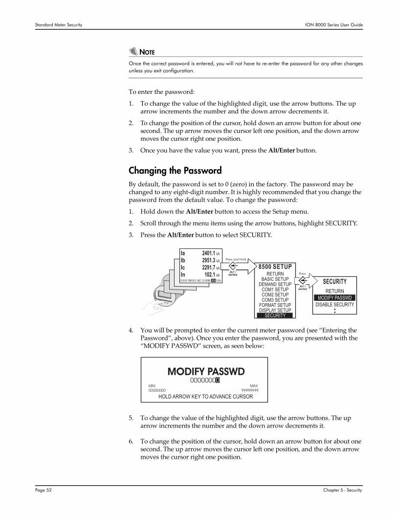
Standard Meter Security ION 8000 Series User Guide
Page 52 Chapter 5 - Security
NOTE
Once the correct password is entered, you will not have to re-enter the password for any other changesunless you exit configuration.
To enter the password:
1. To change the value of the highlighted digit, use the arrow buttons. The up arrow increments the number and the down arrow decrements it.
2. To change the position of the cursor, hold down an arrow button for about one second. The up arrow moves the cursor left one position, and the down arrow moves the cursor right one position.
3. Once you have the value you want, press the Alt/Enter button.
Changing the PasswordBy default, the password is set to 0 (zero) in the factory. The password may be changed to any eight-digit number. It is highly recommended that you change the password from the default value. To change the password:
1. Hold down the Alt/Enter button to access the Setup menu.
2. Scroll through the menu items using the arrow buttons, highlight SECURITY.
3. Press the Alt/Enter button to select SECURITY.
4. You will be prompted to enter the current meter password (see “Entering the Password”, above). Once you enter the password, you are presented with the “MODIFY PASSWD” screen, as seen below:
5. To change the value of the highlighted digit, use the arrow buttons. The up arrow increments the number and the down arrow decrements it.
6. To change the position of the cursor, hold down an arrow button for about one second. The up arrow moves the cursor left one position, and the down arrow moves the cursor right one position.
SECURITY
DISABLE SECURITY
RETURN
MODIFY PASSWD
DEMAND SETUP
COM1 SETUP
COM2 SETUP
COM3 SETUP
SECURITY
FORMAT SETUP
DISPLAY SETUP
RETURN
8500 SETUP
BASIC SETUP
Press
Ia 2401.1 kA
2951.3 kA
2291.7 kA
102.1 kA
IbIcIn
18:30:00 1999.06.01 ABC Q1 NORM 5:00mEOI
Press and Hold
HOLD ARROW KEY TO ADVANCE CURSOR
MODIFY PASSWD
MIN:
00000000
MAX:
99999999
00000000
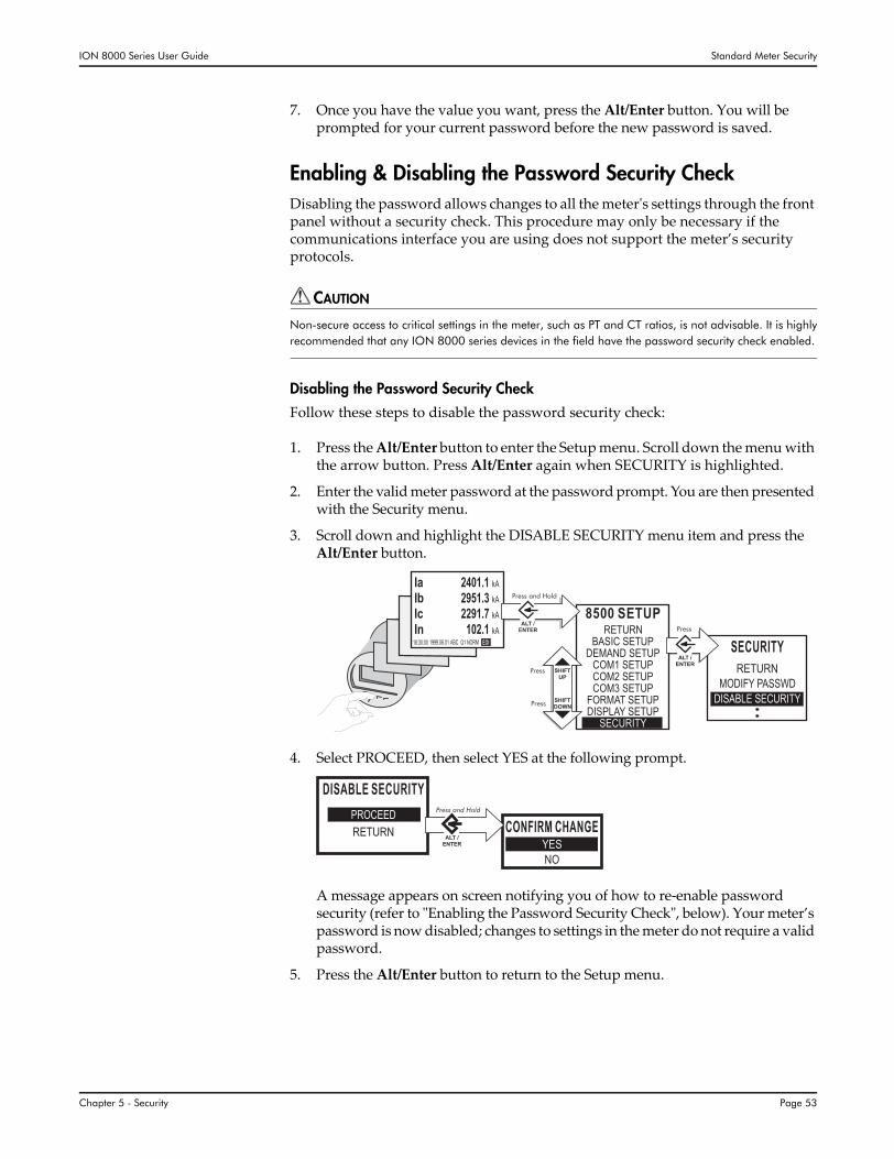
ION 8000 Series User Guide Standard Meter Security
Chapter 5 - Security Page 53
7. Once you have the value you want, press the Alt/Enter button. You will be prompted for your current password before the new password is saved.
Enabling & Disabling the Password Security CheckDisabling the password allows changes to all the meter's settings through the front panel without a security check. This procedure may only be necessary if the communications interface you are using does not support the meter’s security protocols.
CAUTION
Non-secure access to critical settings in the meter, such as PT and CT ratios, is not advisable. It is highlyrecommended that any ION 8000 series devices in the field have the password security check enabled.
Disabling the Password Security Check
Follow these steps to disable the password security check:
1. Press the Alt/Enter button to enter the Setup menu. Scroll down the menu with the arrow button. Press Alt/Enter again when SECURITY is highlighted.
2. Enter the valid meter password at the password prompt. You are then presented with the Security menu.
3. Scroll down and highlight the DISABLE SECURITY menu item and press the Alt/Enter button.
4. Select PROCEED, then select YES at the following prompt.
A message appears on screen notifying you of how to re-enable password security (refer to "Enabling the Password Security Check", below). Your meter’s password is now disabled; changes to settings in the meter do not require a valid password.
5. Press the Alt/Enter button to return to the Setup menu.
SECURITY
DISABLE SECURITY
RETURN
MODIFY PASSWD
DEMAND SETUP
COM1 SETUP
COM2 SETUP
COM3 SETUP
SECURITY
FORMAT SETUP
DISPLAY SETUP
RETURN
8500 SETUP
BASIC SETUP
Press
Press
Press
Ia 2401.1 kA
2951.3 kA
2291.7 kA
102.1 kA
IbIcIn
18:30:00 1999.06.01 ABC Q1 NORM EOI
Press and Hold
DISABLE SECURITY
PROCEED
RETURN CONFIRM CHANGE
NO
YES
Press and Hold
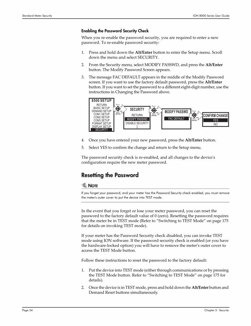
Standard Meter Security ION 8000 Series User Guide
Page 54 Chapter 5 - Security
Enabling the Password Security Check
When you re-enable the password security, you are required to enter a new password. To re-enable password security:
1. Press and hold down the Alt/Enter button to enter the Setup menu. Scroll down the menu and select SECURITY.
2. From the Security menu, select MODIFY PASSWD, and press the Alt/Enter button. The Modify Password Screen appears.
3. The message FAC DEFAULT appears in the middle of the Modify Password screen. If you want to use the factory default password, press the Alt/Enter button. If you want to set the password to a different eight-digit number, use the instructions in Changing the Password above.
4. Once you have entered your new password, press the Alt/Enter button.
5. Select YES to confirm the change and return to the Setup menu.
The password security check is re-enabled, and all changes to the device's configuration require the new meter password.
Resetting the Password
NOTE
If you forget your password, and your meter has the Password Security check enabled, you must removethe meter's outer cover to put the device into TEST mode.
In the event that you forget or lose your meter password, you can reset the password to the factory default value of 0 (zero). Resetting the password requires that the meter be in TEST mode (Refer to “Switching to TEST Mode” on page 175 for details on invoking TEST mode).
If your meter has the Password Security check disabled, you can invoke TEST mode using ION software. If the password security check is enabled (or you have the hardware-locked option) you will have to remove the meter's outer cover to access the TEST Mode button.
Follow these instructions to reset the password to the factory default:
1. Put the device into TEST mode (either through communications or by pressing the TEST Mode button. Refer to “Switching to TEST Mode” on page 175 for details).
2. Once the device is in TEST mode, press and hold down the Alt/Enter button and Demand Reset buttons simultaneously.
SECURITY
DISABLE SECURITY
RETURN
MODIFY PASSWD
DEMAND SETUP
COM1 SETUP
COM2 SETUP
COM3 SETUP
SECURITY
FORMAT SETUP
DISPLAY SETUP
RETURN
8500 SETUP
BASIC SETUP
Press
MODIFY PASSWD
FAC DEFAULTCONFIRM CHANGE
NO
YES
Press
Press
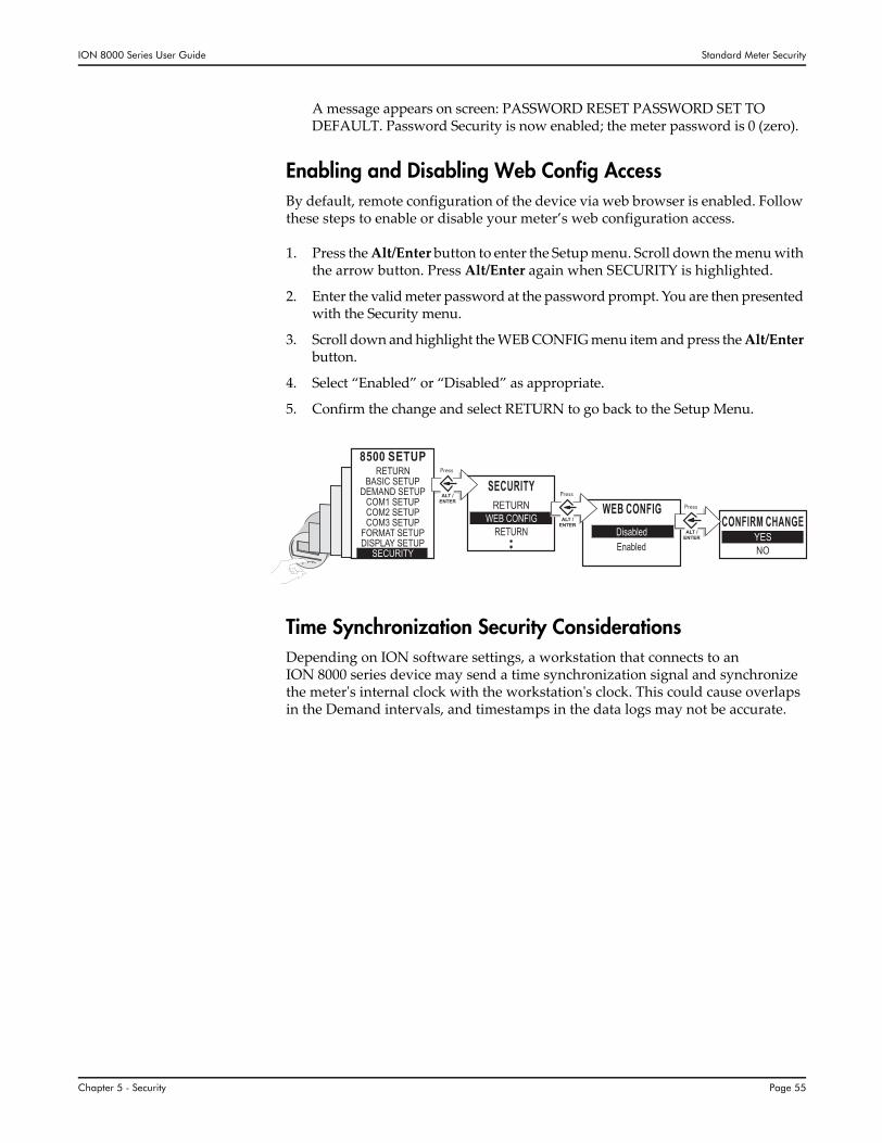
ION 8000 Series User Guide Standard Meter Security
Chapter 5 - Security Page 55
A message appears on screen: PASSWORD RESET PASSWORD SET TO DEFAULT. Password Security is now enabled; the meter password is 0 (zero).
Enabling and Disabling Web Config AccessBy default, remote configuration of the device via web browser is enabled. Follow these steps to enable or disable your meter’s web configuration access.
1. Press the Alt/Enter button to enter the Setup menu. Scroll down the menu with the arrow button. Press Alt/Enter again when SECURITY is highlighted.
2. Enter the valid meter password at the password prompt. You are then presented with the Security menu.
3. Scroll down and highlight the WEB CONFIG menu item and press the Alt/Enter button.
4. Select “Enabled” or “Disabled” as appropriate.
5. Confirm the change and select RETURN to go back to the Setup Menu.
Time Synchronization Security ConsiderationsDepending on ION software settings, a workstation that connects to an ION 8000 series device may send a time synchronization signal and synchronize the meter's internal clock with the workstation's clock. This could cause overlaps in the Demand intervals, and timestamps in the data logs may not be accurate.
SECURITY
RETURN
RETURN
WEB CONFIG
DEMAND SETUP
COM1 SETUP
COM2 SETUP
COM3 SETUP
SECURITY
FORMAT SETUP
DISPLAY SETUP
RETURN
8500 SETUP
BASIC SETUP
Press
WEB CONFIG
DisabledCONFIRM CHANGE
NO
YES
Press
Press
Enabled
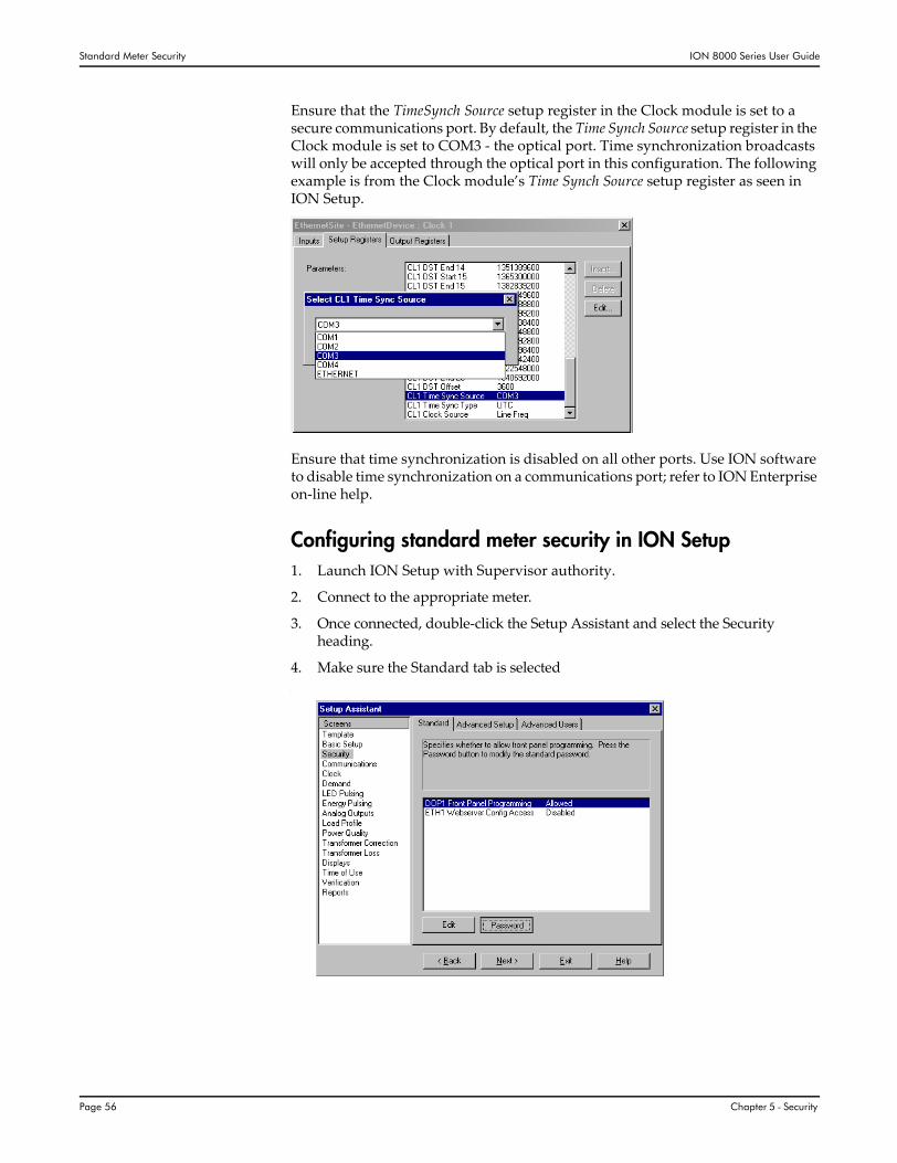
Standard Meter Security ION 8000 Series User Guide
Page 56 Chapter 5 - Security
Ensure that the TimeSynch Source setup register in the Clock module is set to a secure communications port. By default, the Time Synch Source setup register in the Clock module is set to COM3 - the optical port. Time synchronization broadcasts will only be accepted through the optical port in this configuration. The following example is from the Clock module’s Time Synch Source setup register as seen in ION Setup.
Ensure that time synchronization is disabled on all other ports. Use ION software to disable time synchronization on a communications port; refer to ION Enterprise on-line help.
Configuring standard meter security in ION Setup1. Launch ION Setup with Supervisor authority.
2. Connect to the appropriate meter.
3. Once connected, double-click the Setup Assistant and select the Security heading.
4. Make sure the Standard tab is selected.
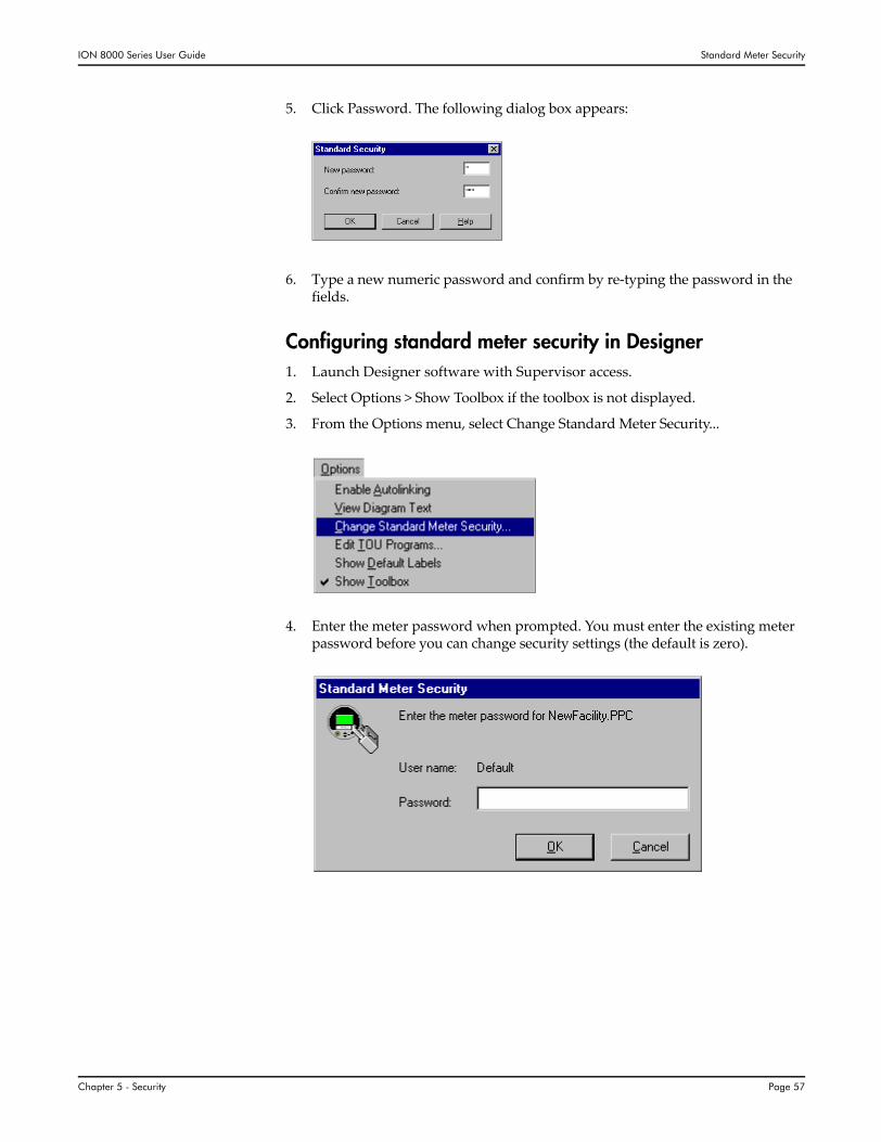
ION 8000 Series User Guide Standard Meter Security
Chapter 5 - Security Page 57
5. Click Password. The following dialog box appears:
6. Type a new numeric password and confirm by re-typing the password in the fields.
Configuring standard meter security in Designer1. Launch Designer software with Supervisor access.
2. Select Options > Show Toolbox if the toolbox is not displayed.
3. From the Options menu, select Change Standard Meter Security...
4. Enter the meter password when prompted. You must enter the existing meter password before you can change security settings (the default is zero).
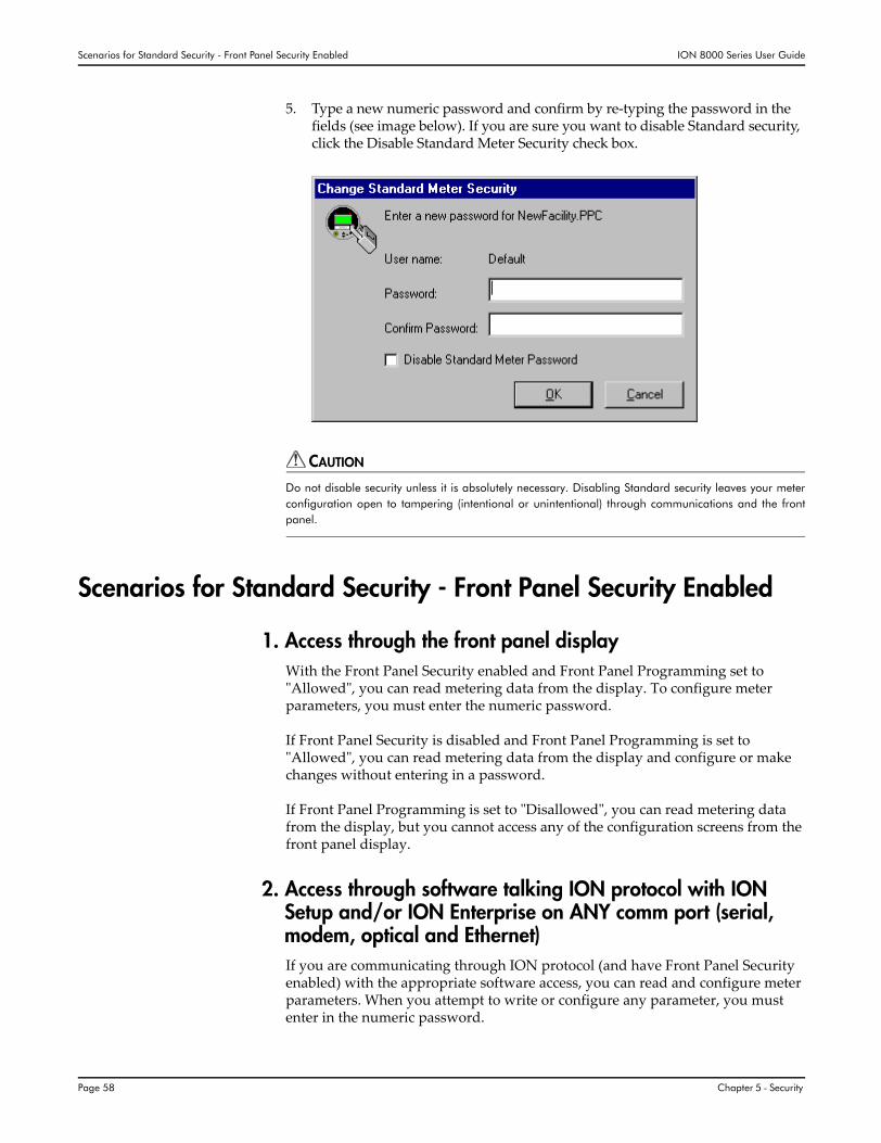
Scenarios for Standard Security - Front Panel Security Enabled ION 8000 Series User Guide
Page 58 Chapter 5 - Security
5. Type a new numeric password and confirm by re-typing the password in the fields (see image below). If you are sure you want to disable Standard security, click the Disable Standard Meter Security check box.
CAUTION
Do not disable security unless it is absolutely necessary. Disabling Standard security leaves your meterconfiguration open to tampering (intentional or unintentional) through communications and the frontpanel.
Scenarios for Standard Security - Front Panel Security Enabled
1. Access through the front panel displayWith the Front Panel Security enabled and Front Panel Programming set to "Allowed", you can read metering data from the display. To configure meter parameters, you must enter the numeric password.
If Front Panel Security is disabled and Front Panel Programming is set to "Allowed", you can read metering data from the display and configure or make changes without entering in a password.
If Front Panel Programming is set to "Disallowed", you can read metering data from the display, but you cannot access any of the configuration screens from the front panel display.
2. Access through software talking ION protocol with ION Setup and/or ION Enterprise on ANY comm port (serial, modem, optical and Ethernet)If you are communicating through ION protocol (and have Front Panel Security enabled) with the appropriate software access, you can read and configure meter parameters. When you attempt to write or configure any parameter, you must enter in the numeric password.
ION 8000 Series User Guide Scenarios for Standard Security - Front Panel Security Enabled
Chapter 5 - Security Page 59
3. Access through Modbus on ANY comm port (serial, modem, optical and Ethernet)On ION meters, Modbus implementation consists of two parts:
i. Modbus Data
Includes the Modbus Slave ION modules.
These modules are configurable as to what data is available and where in the range of Modbus registers this data is placed.
ii. Modbus Setup
Also referred to as the Modbus Map (see Power Measurement’s “Modbus Protocol” document).
Uses fixed functionality and register mapping.
4. Accessing the Modbus data section with Standard SecurityWhen accessing the Modbus Data section with Standard Security enabled, you:
Can read from the data section at all times.
Can write to the data section if the Modbus Slave Module is set to "Unsigned 16Bit Input Mode", and the Front Panel Security is disabled or the password is set to zero.
Cannot write to the data section if the Front Panel Security is enabled and the password is set to a non-zero value.
5. Accessing the Modbus setup section with Standard SecurityWhen accessing the Modbus Setup Section with Standard Security enabled, you:
Can read from the setup section at all times.
Can write to the setup section if the Front Panel Security is disabled or the password is set to zero.
Cannot write to the setup section if the Front Panel Security is enabled and set to a non-zero value.
Time syncs are considered to be a Modbus Setup parameter and follow the same rules above for writing a time sync to the meter. Also, the ION Clock Module must have its Time Sync Source setup register set to the appropriate communication port.
The Modbus Slave module and the Clock module setup registers are only accessible via ION protocol. Their settings are therefore protected by the security settings on the ION device.
Scenarios for Standard Security - Front Panel Security Enabled ION 8000 Series User Guide
Page 60 Chapter 5 - Security
6. Access through DNP 3.0 on ANY serial, modem or optical communication port
NOTE
Currently there is no Ethernet support for DNP 3.0 on ION meters.
If you are communicating through DNP 3.0 protocol over any serial, modem or optical port (and Front Panel Security is enabled), you can read data from the default DNP 3.0 Map without having to enter the numeric password.
If the DNP 3.0 Map is changed to expose control and setup parameters, then you could write to the custom DNP 3.0 Map. The DNP 3.0 Map can only be changed by using ION Setup or ION Enterprise and then the customer must know the numeric password. Time syncs can be sent to the meter in this mode.
7. Access through a standard browser on an Ethernet port via HTTP protocolIf the Front Panel Security is enabled and Webserver Configuration Access is enabled then you will be prompted for the password by your web browser before being allowed to make any configuration changes to the meter. If the Front Panel Security is not enabled, then you will be able to make configuration changes without having to supply the password.
If Webserver Configuration Access is disabled, you can only read data. The default Webserver pages contain real-time data only.
8. Access through FACTORY protocol on a Telnet connection via Ethernet or HyperTerminal on a serial, modem, or optical portIf the Front Panel Security is enabled, you must enter the numeric password to log into the Factory protocol. If Front Panel Security is disabled, logging in via Factory protocol does not require a password.
Once logged in, you can change the following:
1. IP Boot Option - BOOTP or Manual
2. IP Address
3. Subnet Mask
4. Gateway
5. Reset Battery Counters
6. Enable/Disable Front Panel Security
If you wish to change additional configuration settings beyond the above list, contact Power Measurement.
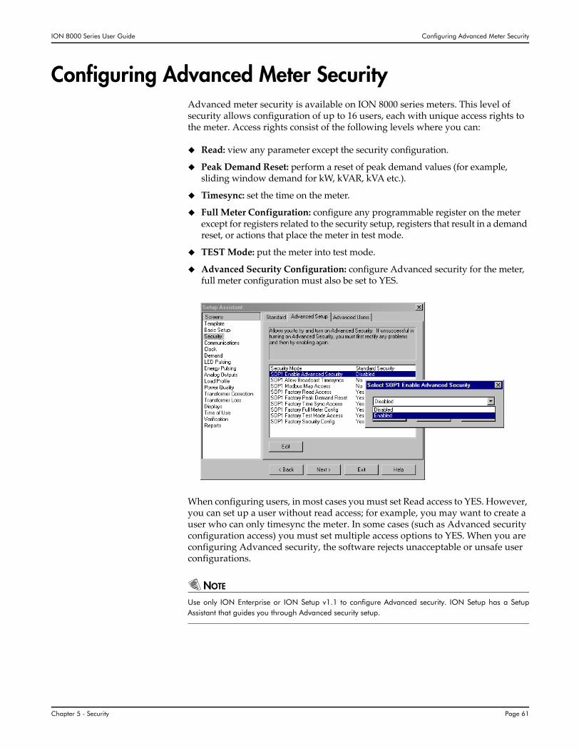
ION 8000 Series User Guide Configuring Advanced Meter Security
Chapter 5 - Security Page 61
Configuring Advanced Meter SecurityAdvanced meter security is available on ION 8000 series meters. This level of security allows configuration of up to 16 users, each with unique access rights to the meter. Access rights consist of the following levels where you can:
Read: view any parameter except the security configuration.
Peak Demand Reset: perform a reset of peak demand values (for example, sliding window demand for kW, kVAR, kVA etc.).
Timesync: set the time on the meter.
Full Meter Configuration: configure any programmable register on the meter except for registers related to the security setup, registers that result in a demand reset, or actions that place the meter in test mode.
TEST Mode: put the meter into test mode.
Advanced Security Configuration: configure Advanced security for the meter, full meter configuration must also be set to YES.
When configuring users, in most cases you must set Read access to YES. However, you can set up a user without read access; for example, you may want to create a user who can only timesync the meter. In some cases (such as Advanced security configuration access) you must set multiple access options to YES. When you are configuring Advanced security, the software rejects unacceptable or unsafe user configurations.
NOTE
Use only ION Enterprise or ION Setup v1.1 to configure Advanced security. ION Setup has a SetupAssistant that guides you through Advanced security setup.
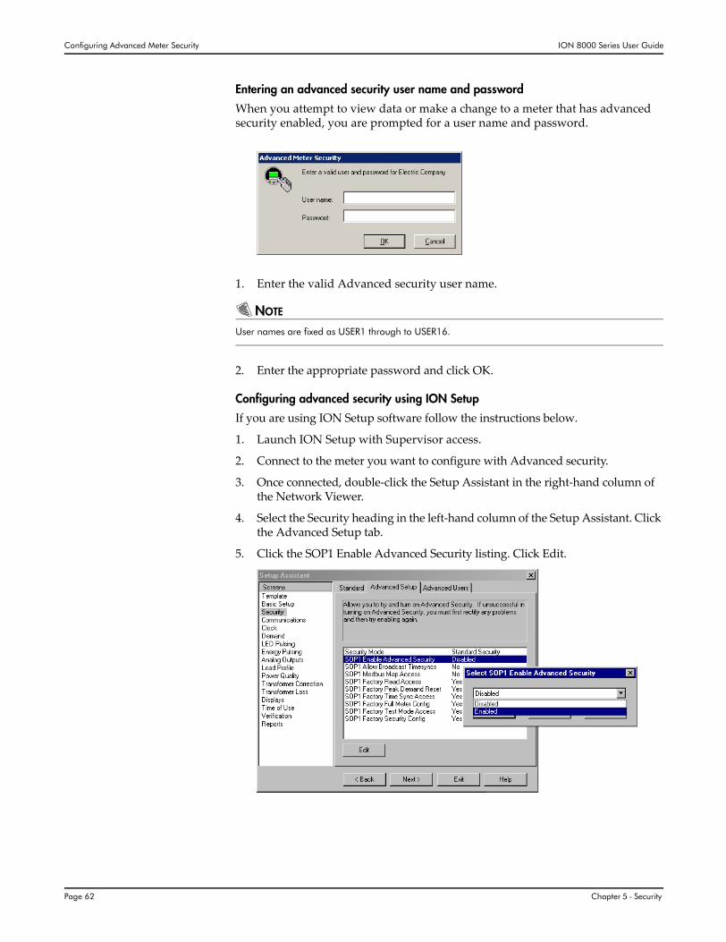
Configuring Advanced Meter Security ION 8000 Series User Guide
Page 62 Chapter 5 - Security
Entering an advanced security user name and password
When you attempt to view data or make a change to a meter that has advanced security enabled, you are prompted for a user name and password.
.
1. Enter the valid Advanced security user name.
NOTE
User names are fixed as USER1 through to USER16.
2. Enter the appropriate password and click OK.
Configuring advanced security using ION Setup
If you are using ION Setup software follow the instructions below.
1. Launch ION Setup with Supervisor access.
2. Connect to the meter you want to configure with Advanced security.
3. Once connected, double-click the Setup Assistant in the right-hand column of the Network Viewer.
4. Select the Security heading in the left-hand column of the Setup Assistant. Click the Advanced Setup tab.
5. Click the SOP1 Enable Advanced Security listing. Click Edit.
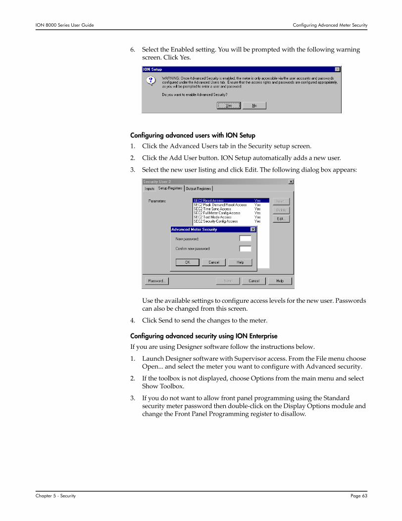
ION 8000 Series User Guide Configuring Advanced Meter Security
Chapter 5 - Security Page 63
6. Select the Enabled setting. You will be prompted with the following warning screen. Click Yes.
Configuring advanced users with ION Setup
1. Click the Advanced Users tab in the Security setup screen.
2. Click the Add User button. ION Setup automatically adds a new user.
3. Select the new user listing and click Edit. The following dialog box appears:
Use the available settings to configure access levels for the new user. Passwords can also be changed from this screen.
4. Click Send to send the changes to the meter.
Configuring advanced security using ION Enterprise
If you are using Designer software follow the instructions below.
1. Launch Designer software with Supervisor access. From the File menu choose Open... and select the meter you want to configure with Advanced security.
2. If the toolbox is not displayed, choose Options from the main menu and select Show Toolbox.
3. If you do not want to allow front panel programming using the Standard security meter password then double-click on the Display Options module and change the Front Panel Programming register to disallow.
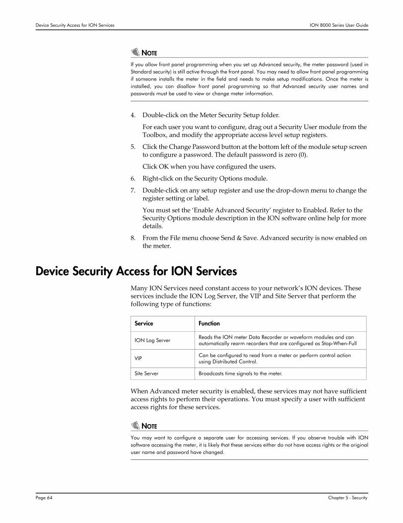
Device Security Access for ION Services ION 8000 Series User Guide
Page 64 Chapter 5 - Security
NOTE
If you allow front panel programming when you set up Advanced security, the meter password (used inStandard security) is still active through the front panel. You may need to allow front panel programmingif someone installs the meter in the field and needs to make setup modifications. Once the meter isinstalled, you can disallow front panel programming so that Advanced security user names andpasswords must be used to view or change meter information.
4. Double-click on the Meter Security Setup folder.
For each user you want to configure, drag out a Security User module from the Toolbox, and modify the appropriate access level setup registers.
5. Click the Change Password button at the bottom left of the module setup screen to configure a password. The default password is zero (0).
Click OK when you have configured the users.
6. Right-click on the Security Options module.
7. Double-click on any setup register and use the drop-down menu to change the register setting or label.
You must set the ‘Enable Advanced Security’ register to Enabled. Refer to the Security Options module description in the ION software online help for more details.
8. From the File menu choose Send & Save. Advanced security is now enabled on the meter.
Device Security Access for ION Services Many ION Services need constant access to your network’s ION devices. These services include the ION Log Server, the VIP and Site Server that perform the following type of functions:
When Advanced meter security is enabled, these services may not have sufficient access rights to perform their operations. You must specify a user with sufficient access rights for these services.
NOTE
You may want to configure a separate user for accessing services. If you observe trouble with IONsoftware accessing the meter, it is likely that these services either do not have access rights or the originaluser name and password have changed.
Service Function
ION Log Server Reads the ION meter Data Recorder or waveform modules and can automatically rearm recorders that are configured as Stop-When-Full
VIP Can be configured to read from a meter or perform control action using Distributed Control.
Site Server Broadcasts time signals to the meter.
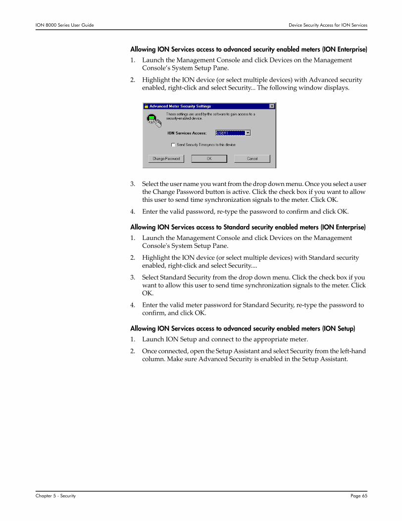
ION 8000 Series User Guide Device Security Access for ION Services
Chapter 5 - Security Page 65
Allowing ION Services access to advanced security enabled meters (ION Enterprise)
1. Launch the Management Console and click Devices on the Management Console’s System Setup Pane.
2. Highlight the ION device (or select multiple devices) with Advanced security enabled, right-click and select Security... The following window displays.
3. Select the user name you want from the drop down menu. Once you select a user the Change Password button is active. Click the check box if you want to allow this user to send time synchronization signals to the meter. Click OK.
4. Enter the valid password, re-type the password to confirm and click OK.
Allowing ION Services access to Standard security enabled meters (ION Enterprise)
1. Launch the Management Console and click Devices on the Management Console's System Setup Pane.
2. Highlight the ION device (or select multiple devices) with Standard security enabled, right-click and select Security....
3. Select Standard Security from the drop down menu. Click the check box if you want to allow this user to send time synchronization signals to the meter. Click OK.
4. Enter the valid meter password for Standard Security, re-type the password to confirm, and click OK.
Allowing ION Services access to advanced security enabled meters (ION Setup)
1. Launch ION Setup and connect to the appropriate meter.
2. Once connected, open the Setup Assistant and select Security from the left-hand column. Make sure Advanced Security is enabled in the Setup Assistant.
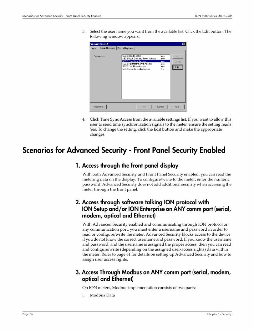
Scenarios for Advanced Security - Front Panel Security Enabled ION 8000 Series User Guide
Page 66 Chapter 5 - Security
3. Select the user name you want from the available list. Click the Edit button. The following window appears:
4. Click Time Sync Access from the available settings list. If you want to allow this user to send time synchronization signals to the meter, ensure the setting reads Yes. To change the setting, click the Edit button and make the appropriate changes.
Scenarios for Advanced Security - Front Panel Security Enabled
1. Access through the front panel displayWith both Advanced Security and Front Panel Security enabled, you can read the metering data on the display. To configure/write to the meter, enter the numeric password. Advanced Security does not add additional security when accessing the meter through the front panel.
2. Access through software talking ION protocol with ION Setup and/or ION Enterprise on ANY comm port (serial, modem, optical and Ethernet)With Advanced Security enabled and communicating through ION protocol on any communication port, you must enter a username and password in order to read or configure/write the meter. Advanced Security blocks access to the device if you do not know the correct username and password. If you know the username and password, and the username is assigned the proper access, then you can read and configure/write (depending on the assigned user-access rights) data within the meter. Refer to page 61 for details on setting up Advanced Security and how to assign user access rights.
3. Access Through Modbus on ANY comm port (serial, modem, optical and Ethernet)On ION meters, Modbus implementation consists of two parts:
i. Modbus Data
ION 8000 Series User Guide Scenarios for Advanced Security - Front Panel Security Enabled
Chapter 5 - Security Page 67
Includes the Modbus Slave ION modules.
These modules are configurable as to what data is available and where in the range of Modbus registers this data is placed.
ii. Modbus Setup
Also referred to as the Modbus Map (see Power Measurement’s “Modbus Protocol” document.
Uses fixed functionality and register mapping.
From an Advanced Security point of view, however, the Modbus Data and Setup sections operate somewhat differently.
When accessing the Modbus Data Section with Advanced Security Enabled, you:
Can still read from the data section at all times.
Can write to the data section if the Modbus Slave Module is set to "Unsigned 16Bit Input Mode", and the "Modbus Map Access" is set to "Yes".
Cannot write to the data section if "Modbus Map Access" is set to "No".
When accessing the Modbus Setup Section with Advanced Security Enabled, you:
Can read from and write to the data section if "Modbus Map Access" is set to "Yes".
Cannot read from or write to the data section if "MODBUS Map Access" is set to "No".
You can write a time sync only if "MODBUS Map Access" and "Allow Broadcast Time syncs" are both set to "Yes", and the ION Clock Module's "Time Sync Source" setup register is set to the appropriate communication port.
Since the Modbus Map Access, the Modbus Slave module, and the Clock module setup registers are only accessible via ION protocol, their settings are protected by the security settings on the ION device.
4. Access through DNP 3.0 on ANY serial, modem or optical port
NOTE
Currently there is no Ethernet support for DNP 3.0 on ION meters.
With Advanced Security enabled and communicating through DNP 3.0 protocol over any serial, modem or optical port, you can read from the default DNP 3.0 Map. If the DNP 3.0 Map is changed to expose control and setup parameters, then you can write to the custom DNP 3.0 Map. Any changes to the DNP 3.0 Map or the Security Options Module can only be changed by using ION Setup or ION Enterprise and the customer must know the proper Advanced Security username and password. Time syncs can be sent to the meter in this mode without having to enter in a username and password.
Scenarios for Advanced Security - Front Panel Security Enabled ION 8000 Series User Guide
Page 68 Chapter 5 - Security
5. Access through a standard browser on an Ethernet port via http protocolIf Advanced Security is enabled and the Web Access Read Security setup register in the Security Options Module is set to YES, you must enter in the proper Advanced Security username and password before gaining read access to the device through a standard browser. If you have the proper username and password, the next level of security is the Webserver Configuration Access setting. If the Webserver Configuration Access disabled, you can only read metering data.
If the Web Access Read Security setup register is set to NO, then you will be able to read web pages on the device without having to provide an Advanced Security username and password. However, if you attempt to make configuration changes, you will be prompted for the Advanced Security username and password.
6. Access Through FACTORY protocol on a Telnet connection via Ethernet or HyperTerminal on a serial, modem, or optical portAdvanced Security does not affect the Factory protocol. Therefore, if Front Panel Security is enabled, you will have to enter the password to log into the Factory protocol. If the Front Panel Security is disabled you can log into the Factory protocol without supplying a password.
Once logged in, you can change the following:
1. IP Boot Option - BOOTP or Manual
2. IP Address
3. Subnet Mask
4. Gateway
5. Reset Battery Counters
6. Enable/Disable Front Panel Security
If you wish to change additional configuration settings beyond the items listed above, you must contact Power Measurement.
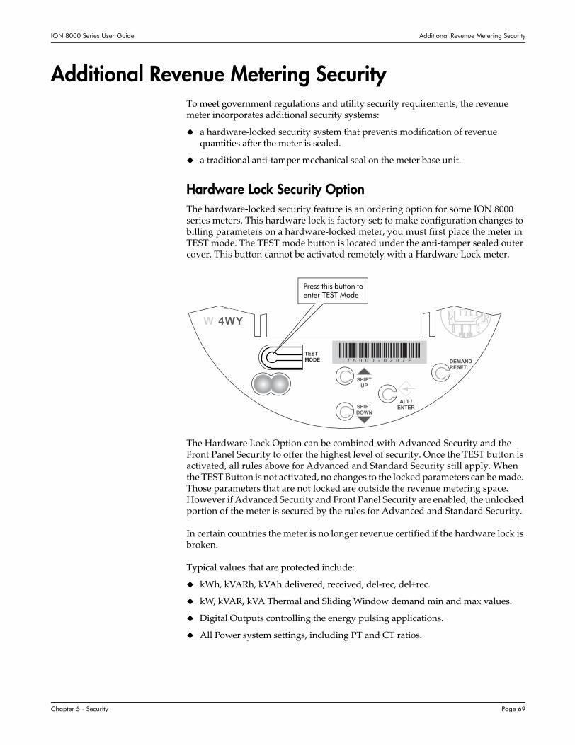
ION 8000 Series User Guide Additional Revenue Metering Security
Chapter 5 - Security Page 69
Additional Revenue Metering SecurityTo meet government regulations and utility security requirements, the revenue meter incorporates additional security systems:
a hardware-locked security system that prevents modification of revenue quantities after the meter is sealed.
a traditional anti-tamper mechanical seal on the meter base unit.
Hardware Lock Security OptionThe hardware-locked security feature is an ordering option for some ION 8000 series meters. This hardware lock is factory set; to make configuration changes to billing parameters on a hardware-locked meter, you must first place the meter in TEST mode. The TEST mode button is located under the anti-tamper sealed outer cover. This button cannot be activated remotely with a Hardware Lock meter.
The Hardware Lock Option can be combined with Advanced Security and the Front Panel Security to offer the highest level of security. Once the TEST button is activated, all rules above for Advanced and Standard Security still apply. When the TEST Button is not activated, no changes to the locked parameters can be made. Those parameters that are not locked are outside the revenue metering space. However if Advanced Security and Front Panel Security are enabled, the unlocked portion of the meter is secured by the rules for Advanced and Standard Security.
In certain countries the meter is no longer revenue certified if the hardware lock is broken.
Typical values that are protected include:
kWh, kVARh, kVAh delivered, received, del-rec, del+rec.
kW, kVAR, kVA Thermal and Sliding Window demand min and max values.
Digital Outputs controlling the energy pulsing applications.
All Power system settings, including PT and CT ratios.
ALT /ENTER
W
SHIFT
UP
SHIFT
DOWN
DEMAND
RESET
TEST
MODE
4WY
Press this button to enter TEST Mode
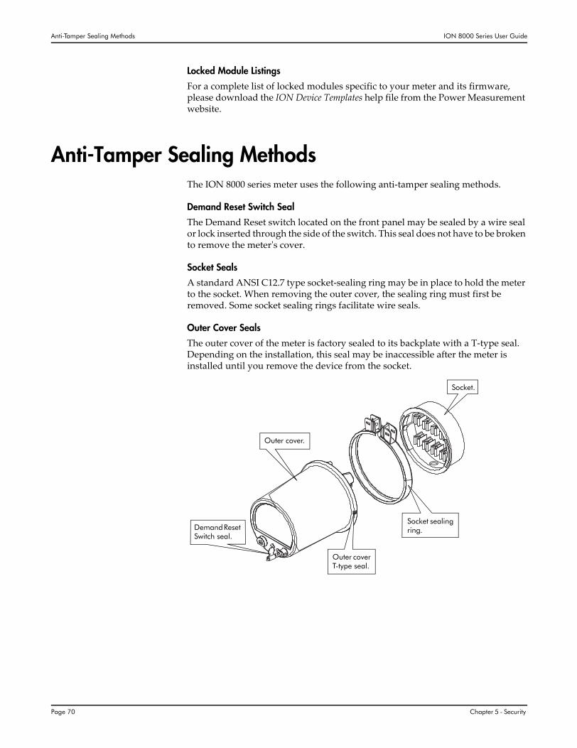
Anti-Tamper Sealing Methods ION 8000 Series User Guide
Page 70 Chapter 5 - Security
Locked Module Listings
For a complete list of locked modules specific to your meter and its firmware, please download the ION Device Templates help file from the Power Measurement website.
Anti-Tamper Sealing MethodsThe ION 8000 series meter uses the following anti-tamper sealing methods.
Demand Reset Switch Seal
The Demand Reset switch located on the front panel may be sealed by a wire seal or lock inserted through the side of the switch. This seal does not have to be broken to remove the meter's cover.
Socket Seals
A standard ANSI C12.7 type socket-sealing ring may be in place to hold the meter to the socket. When removing the outer cover, the sealing ring must first be removed. Some socket sealing rings facilitate wire seals.
Outer Cover Seals
The outer cover of the meter is factory sealed to its backplate with a T-type seal. Depending on the installation, this seal may be inaccessible after the meter is installed until you remove the device from the socket.
Demand Reset Switch seal.
Socket sealing ring.
Socket.
Outer cover.
Outer cover T-type seal.
Page 71
6 CommunicationsThis chapter includes general instructions for connecting and configuring all the communication ports on your meter.
For specific installation steps and meter specifications, consult your ION 8000 Installation Guide.
In this chapter
Communications Overview . . . . . . . . . . . . . . . . . . . . . . . . . . . . . . . . . . . . 72
Communications Options . . . . . . . . . . . . . . . . . . . . . . . . . . . . . . . . . . . . . 73ION 8500/ION 8400 ............................................................................................... 73Optional Switchboard Breakout Panel ............................................................... 74ION 8300 ................................................................................................................. 74IRIG-B GPS Time Synchronization ..................................................................... 75Communications Accessories .............................................................................. 75
Serial Connections . . . . . . . . . . . . . . . . . . . . . . . . . . . . . . . . . . . . . . . . . . 76RS-232 Connections . . . . . . . . . . . . . . . . . . . . . . . . . . . . . . . . . . . . . . . . . . . . . . . . . . . 77RS-485 Connections . . . . . . . . . . . . . . . . . . . . . . . . . . . . . . . . . . . . . . . . . . . . . . . . . . . 78
General Bus Wiring Considerations ................................................................... 79RS-485 Connection Methods to Avoid ............................................................... 79Communications Break-out Cable ...................................................................... 80
Configuring the Optical Port . . . . . . . . . . . . . . . . . . . . . . . . . . . . . . . . . . . . . . . . . . . 81Using the front panel ............................................................................................ 81Using ION Setup ................................................................................................... 81Using ION Enterprise ........................................................................................... 82
Configuring Ethernet Connections . . . . . . . . . . . . . . . . . . . . . . . . . . . . . . . . . . . . . . 83Using the front panel ............................................................................................ 83Using ION Setup ................................................................................................... 84Using ION Enterprise ........................................................................................... 84
Configuring EtherGate Connections . . . . . . . . . . . . . . . . . . . . . . . . . . . . . . . . . . . . . 85Using the front panel ............................................................................................ 85Using ION Setup ................................................................................................... 86Using ION Enterprise ........................................................................................... 87
Internal Modem Connections . . . . . . . . . . . . . . . . . . . . . . . . . . . . . . . . . . . 88ModemInit Setup Register ................................................................................... 88The ModemGate Protocol .................................................................................... 91
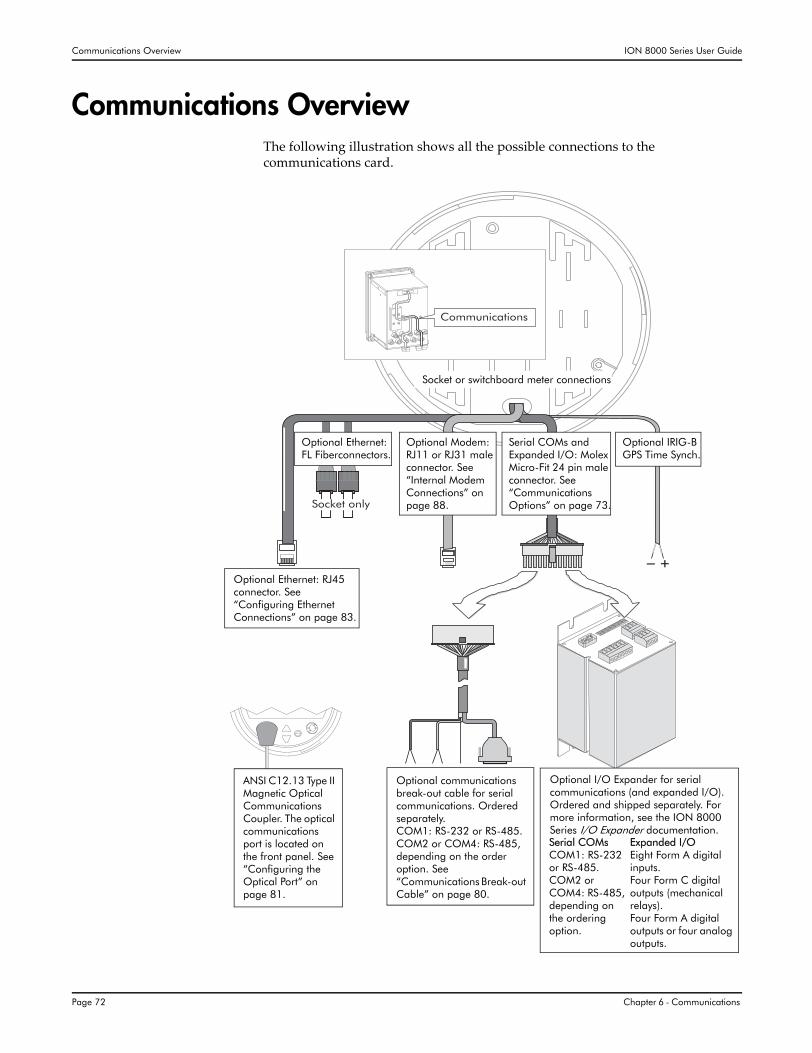
Communications Overview ION 8000 Series User Guide
Page 72 Chapter 6 - Communications
Communications OverviewThe following illustration shows all the possible connections to the communications card.
Optional Modem: RJ11 or RJ31 male connector. See “Internal Modem Connections” on page 88.
Serial COMs and Expanded I/O: Molex Micro-Fit 24 pin male connector. See “Communications Options” on page 73.
Optional I/O Expander for serial communications (and expanded I/O). Ordered and shipped separately. For more information, see the ION 8000 Series I/O Expander documentation. Serial COMs COM1: RS-232 or RS-485.COM2 or COM4: RS-485, depending on the ordering option.
Expanded I/OEight Form A digital inputs.Four Form C digital outputs (mechanical relays). Four Form A digital outputs or four analog outputs.
Socket or switchboard meter connections
Optional communications break-out cable for serial communications. Ordered separately.COM1: RS-232 or RS-485.COM2 or COM4: RS-485, depending on the order option. See “Communications Break-out Cable” on page 80.
ANSI C12.13 Type II Magnetic Optical Communications Coupler. The optical communications port is located on the front panel. See “Configuring the Optical Port” on page 81.
Optional Ethernet: RJ45 connector. See “Configuring Ethernet Connections” on page 83.
Optional IRIG-B GPS Time Synch.
Optional Ethernet: FL Fiberconnectors.
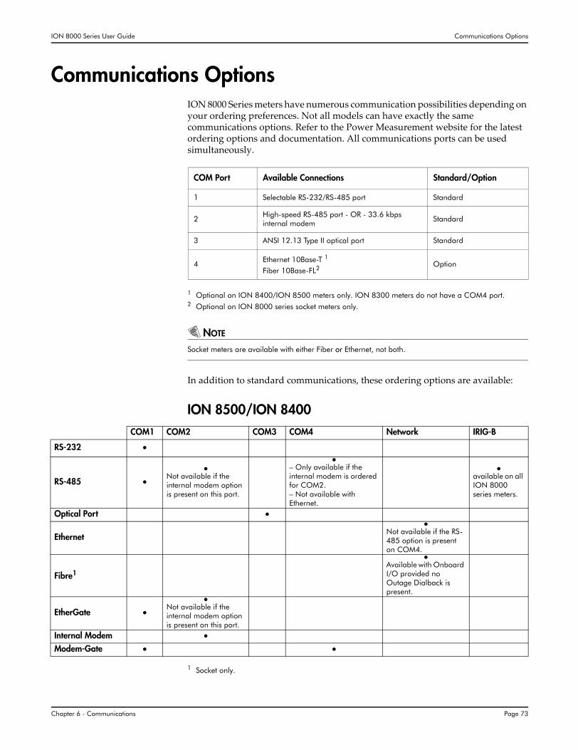
ION 8000 Series User Guide Communications Options
Chapter 6 - Communications Page 73
Communications OptionsION 8000 Series meters have numerous communication possibilities depending on your ordering preferences. Not all models can have exactly the same communications options. Refer to the Power Measurement website for the latest ordering options and documentation. All communications ports can be used simultaneously.
1 Optional on ION 8400/ION 8500 meters only. ION 8300 meters do not have a COM4 port.2 Optional on ION 8000 series socket meters only.
NOTE
Socket meters are available with either Fiber or Ethernet, not both.
In addition to standard communications, these ordering options are available:
ION 8500/ION 8400
1 Socket only.
COM Port Available Connections Standard/Option
1 Selectable RS-232/RS-485 port Standard
2 High-speed RS-485 port - OR - 33.6 kbps internal modem Standard
3 ANSI 12.13 Type II optical port Standard
4 Ethernet 10Base-T 1
Fiber 10Base-FL2 Option
COM1 COM2 COM3 COM4 Network IRIG-B
RS-232
RS-485Not available if the internal modem option is present on this port.
– Only available if the internal modem is ordered for COM2. – Not available with Ethernet.
available on all ION 8000 series meters.
Optical Port
EthernetNot available if the RS-485 option is present on COM4.
Fibre1Available with Onboard I/O provided no Outage Dialback is present.
EtherGate Not available if the internal modem option is present on this port.
Internal ModemModem-Gate
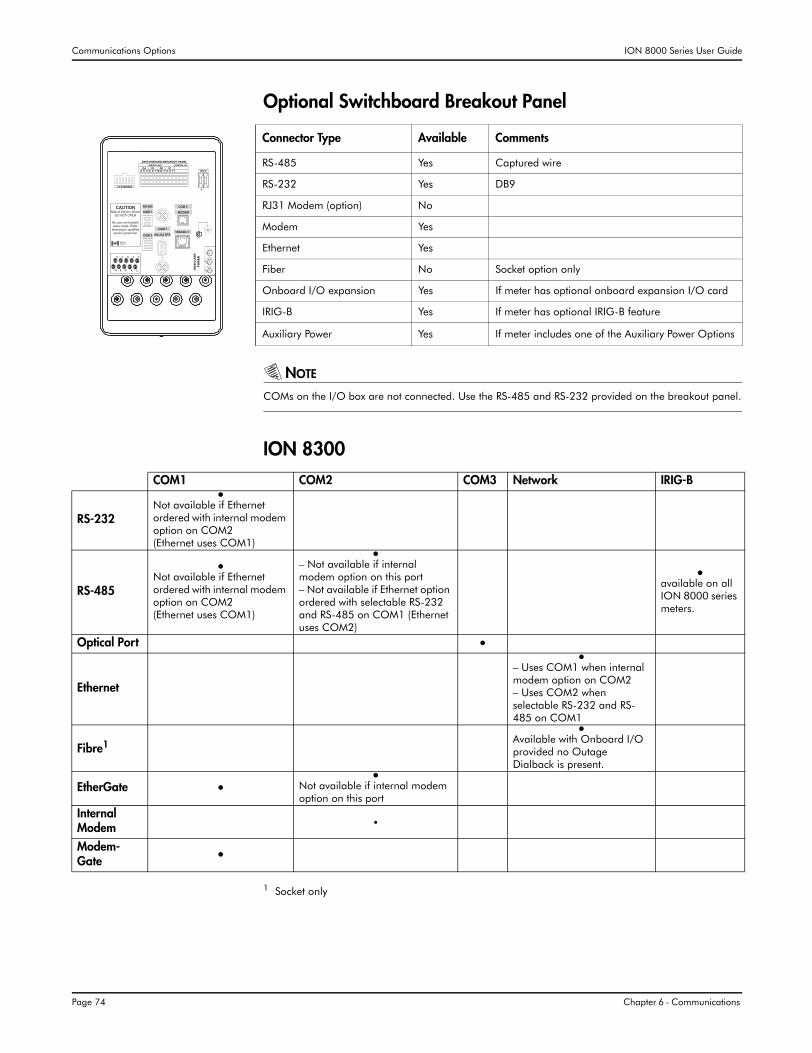
Communications Options ION 8000 Series User Guide
Page 74 Chapter 6 - Communications
Optional Switchboard Breakout Panel
NOTE
COMs on the I/O box are not connected. Use the RS-485 and RS-232 provided on the breakout panel.
ION 8300
1 Socket only
Connector Type Available Comments
RS-485 Yes Captured wire
RS-232 Yes DB9
RJ31 Modem (option) No
Modem Yes
Ethernet Yes
Fiber No Socket option only
Onboard I/O expansion Yes If meter has optional onboard expansion I/O card
IRIG-B Yes If meter has optional IRIG-B feature
Auxiliary Power Yes If meter includes one of the Auxiliary Power Options
COM1 COM2 COM3 Network IRIG-B
RS-232Not available if Ethernet ordered with internal modem option on COM2(Ethernet uses COM1)
RS-485Not available if Ethernet ordered with internal modem option on COM2(Ethernet uses COM1)
– Not available if internal modem option on this port– Not available if Ethernet option ordered with selectable RS-232 and RS-485 on COM1 (Ethernet uses COM2)
available on all ION 8000 series meters.
Optical Port
Ethernet
– Uses COM1 when internal modem option on COM2– Uses COM2 when selectable RS-232 and RS-485 on COM1
Fibre1 Available with Onboard I/O provided no Outage Dialback is present.
EtherGate Not available if internal modem option on this port
Internal ModemModem-Gate
ION 8000 Series User Guide Communications Options
Chapter 6 - Communications Page 75
NOTE
The ION 8300 meter Ethernet option can share a communications channel with COM1 or COM2,depending on the ordering options. There is no COM4 port.
IRIG-B GPS Time SynchronizationIRIG-B cannot be configured via the meter’s front panel. See the IRIG-B Product Option document for configuration procedures.
Communications AccessoriesThe following accessories are currently available as separate products:
I/O Expander
The I/O Expander connects with the male Molex connector on the meter to provide I/O capabilities as well as access to standard serial communications ports. Refer to the I/O Expander Installation Guide for complete details about this device.
Communications break-out cable
The communications break-out cable connects with the male Molex connector on the meter. This is a pre-made cable that provides access to the standard serial communications ports on the meter.
Molex extension cables
Depending on your ordering preference, the molex extension cables add either 5 or 15 feet (1.5 or 4.5 meters) to the molex cable on the meter.
Optical probe
The optical probe attaches to the optical port on the front of the meter and allows on-site communications (e.g. with a laptop computer).
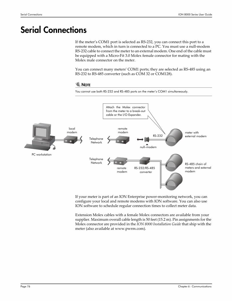
Serial Connections ION 8000 Series User Guide
Page 76 Chapter 6 - Communications
Serial ConnectionsIf the meter’s COM1 port is selected as RS-232, you can connect this port to a remote modem, which in turn is connected to a PC. You must use a null-modem RS-232 cable to connect the meter to an external modem. One end of the cable must be equipped with a Micro-Fit 3.0 Molex female connector for mating with the Molex male connector on the meter.
You can connect many meters’ COM1 ports; they are selected as RS-485 using an RS-232 to RS-485 converter (such as COM 32 or COM128).
NOTE
You cannot use both RS-232 and RS-485 ports on the meter’s COM1 simultaneously.
If your meter is part of an ION Enterprise power-monitoring network, you can configure your local and remote modems with ION software. You can also use ION software to schedule regular connection times to collect meter data.
Extension Molex cables with a female Molex connectors are available from your supplier. Maximum overall cable length is 50 feet (15.2 m). Pin assignments for the Molex connector are provided in the ION 8000 Installation Guide that ship with the meter (also available at www.pwrm.com).
null–modem
meter withexternal modem
RS-485 chain ofmeters and externalmodem
RS-232/RS-485converter
remote
Network
TelephoneNetwork
Telephone
PC workstation
local
RS-232modem
modem
remotemodem
Attach the Molex connectorfrom the meter to a break-outcable or the I/O Expander.
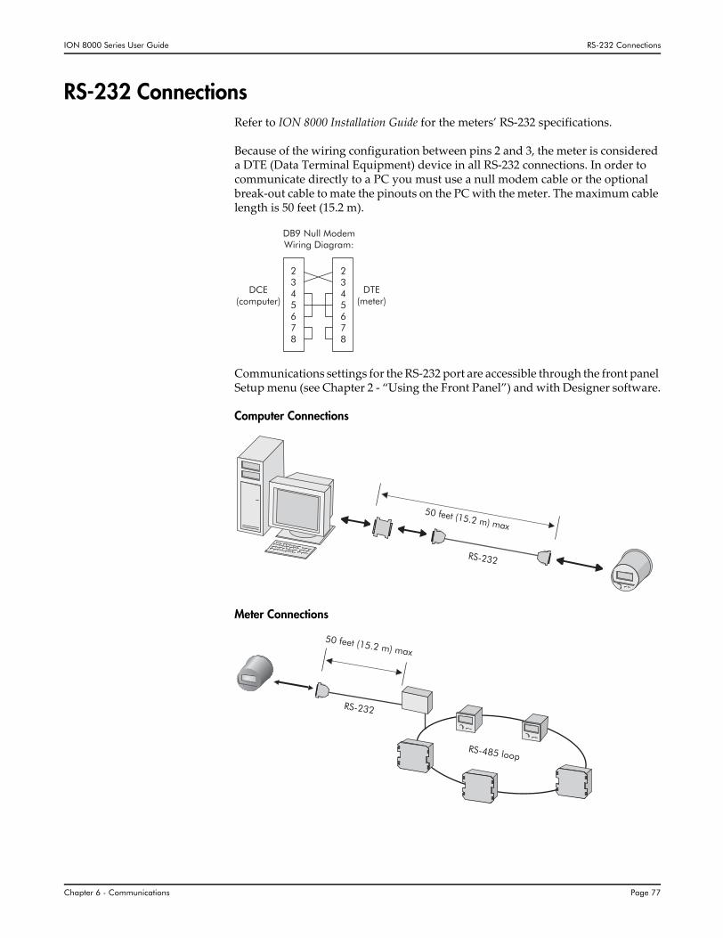
ION 8000 Series User Guide RS-232 Connections
Chapter 6 - Communications Page 77
RS-232 ConnectionsRefer to ION 8000 Installation Guide for the meters’ RS-232 specifications.
Because of the wiring configuration between pins 2 and 3, the meter is considered a DTE (Data Terminal Equipment) device in all RS-232 connections. In order to communicate directly to a PC you must use a null modem cable or the optional break-out cable to mate the pinouts on the PC with the meter. The maximum cable length is 50 feet (15.2 m).
Communications settings for the RS-232 port are accessible through the front panel Setup menu (see Chapter 2 - “Using the Front Panel”) and with Designer software.
Computer Connections
Meter Connections
2345678
2345678
DB9 Null ModemWiring Diagram:
DCE(computer)
DTE(meter)
RS-232
50 feet (15.2 m) max
RS-232
RS-485 loop
50 feet (15.2 m) max
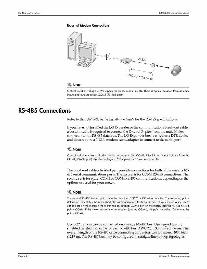
RS-485 Connections ION 8000 Series User Guide
Page 78 Chapter 6 - Communications
External Modem Connections
NOTE
Optical isolation voltage is 750 V peak for 10 seconds at 62 Hz. There is optical isolation from all otherinputs and outputs except COM1 (RS-485 port).
RS-485 ConnectionsRefer to the ION 8000 Series Installation Guide for the RS-485 specifications.
If you have not installed the I/O Expander or the communications break-out cable, a custom cable is required to connect the D+ and D- pins from the male Molex connector to the RS-485 data bus. The I/O Expander box is wired as a DTE device and does require a NULL modem cable/adapter to connect to the serial port.
NOTE
Optical isolation is from all other inputs and outputs (the COM1, RS-485 port is not isolated from theCOM1, RS-232 port). Isolation voltage is 750 V peak for 10 seconds at 60 Hz.
The break-out cable’s twisted pair provide connections for both of the meter’s RS-485 serial communications ports. The first set is for COM1 RS-485 connections. The second set is for either COM2 or COM4 RS-485 communications, depending on the options ordered for your meter.
NOTE
The second RS-485 twisted pair connection is either COM2 or COM4 or inactive. The following pointsdetermine their status, however check the communications LEDs on the side of your meter to see whichoptions are on the meter: If the meter has an optional COM4 port on the meter, then the RS-485 twistedpair is COM4. If the meter has an internal modem (and no COM4), the pair is inactive. Otherwise, thepair is COM2.
Up to 32 devices can be connected on a single RS-485 bus. Use a good quality shielded twisted pair cable for each RS-485 bus, AWG 22 (0.33 mm2) or larger. The overall length of the RS-485 cable connecting all devices cannot exceed 4000 feet (1219 m). The RS-485 bus may be configured in straight-line or loop topologies.
50 feet (15.2 m) max
RS-232
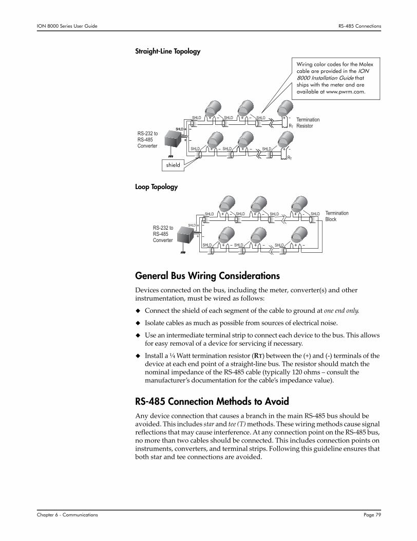
ION 8000 Series User Guide RS-485 Connections
Chapter 6 - Communications Page 79
Straight-Line Topology
Loop Topology
General Bus Wiring ConsiderationsDevices connected on the bus, including the meter, converter(s) and other instrumentation, must be wired as follows:
Connect the shield of each segment of the cable to ground at one end only.
Isolate cables as much as possible from sources of electrical noise.
Use an intermediate terminal strip to connect each device to the bus. This allows for easy removal of a device for servicing if necessary.
Install a ¼ Watt termination resistor (RT) between the (+) and (-) terminals of the device at each end point of a straight-line bus. The resistor should match the nominal impedance of the RS-485 cable (typically 120 ohms – consult the manufacturer’s documentation for the cable’s impedance value).
RS-485 Connection Methods to AvoidAny device connection that causes a branch in the main RS-485 bus should be avoided. This includes star and tee (T) methods. These wiring methods cause signal reflections that may cause interference. At any connection point on the RS-485 bus, no more than two cables should be connected. This includes connection points on instruments, converters, and terminal strips. Following this guideline ensures that both star and tee connections are avoided.
RS-232 to
RS-485
Converter
Termination
ResistorSHLD
+ SHLD + SHLD +
RT
SHLD + SHLD ++ SHLD
RT
SHLD
+
+
SHLD +
+
shield
Wiring color codes for the Molex cable are provided in the ION 8000 Installation Guide that ships with the meter and are available at www.pwrm.com.
SHLD
+ SHLD + SHLD
SHLD + SHLD +
SHLD
+
+
RS-232 to
RS-485
Converter
Termination
Block+ SHLD
SHLD +
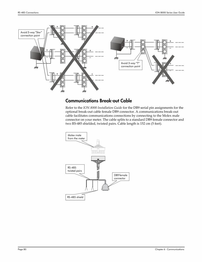
RS-485 Connections ION 8000 Series User Guide
Page 80 Chapter 6 - Communications
Communications Break-out CableRefer to the ION 8000 Installation Guide for the DB9 serial pin assignments for the optional break-out cable female DB9 connector. A communications break-out cable facilitates communications connections by connecting to the Molex male connector on your meter. The cable splits to a standard DB9 female connector and two RS-485 shielded, twisted pairs. Cable length is 152 cm (5 feet).
Avoid 3-way “Star” connection point
Avoid 3-way “T” connection point
Molex male from the meter
RS-485 twisted pairs
RS-485 shield
DB9 female connector
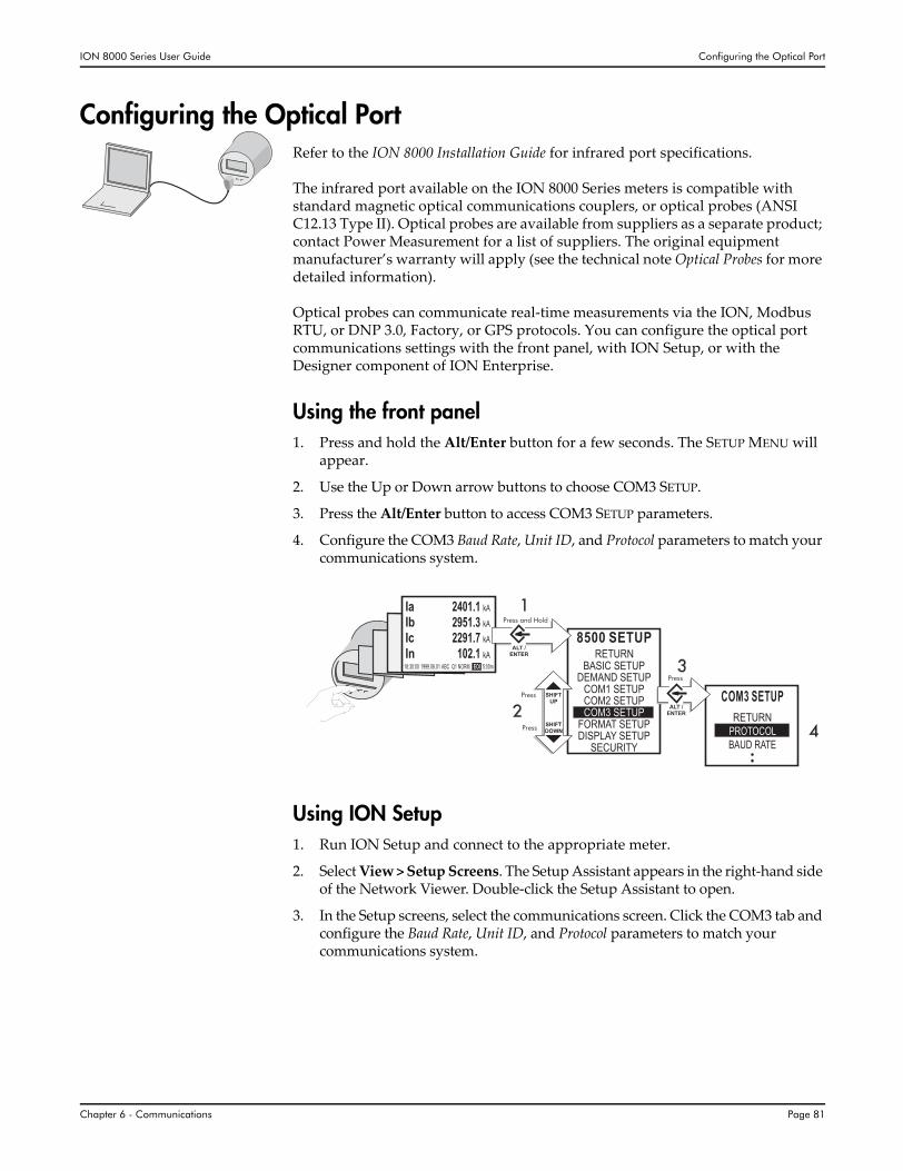
ION 8000 Series User Guide Configuring the Optical Port
Chapter 6 - Communications Page 81
Configuring the Optical PortRefer to the ION 8000 Installation Guide for infrared port specifications.
The infrared port available on the ION 8000 Series meters is compatible with standard magnetic optical communications couplers, or optical probes (ANSI C12.13 Type II). Optical probes are available from suppliers as a separate product; contact Power Measurement for a list of suppliers. The original equipment manufacturer’s warranty will apply (see the technical note Optical Probes for more detailed information).
Optical probes can communicate real-time measurements via the ION, Modbus RTU, or DNP 3.0, Factory, or GPS protocols. You can configure the optical port communications settings with the front panel, with ION Setup, or with the Designer component of ION Enterprise.
Using the front panel1. Press and hold the Alt/Enter button for a few seconds. The SETUP MENU will
appear.
2. Use the Up or Down arrow buttons to choose COM3 SETUP.
3. Press the Alt/Enter button to access COM3 SETUP parameters.
4. Configure the COM3 Baud Rate, Unit ID, and Protocol parameters to match your communications system.
Using ION Setup1. Run ION Setup and connect to the appropriate meter.
2. Select View > Setup Screens. The Setup Assistant appears in the right-hand side of the Network Viewer. Double-click the Setup Assistant to open.
3. In the Setup screens, select the communications screen. Click the COM3 tab and configure the Baud Rate, Unit ID, and Protocol parameters to match your communications system.
COM3 SETUP
BAUD RATE
RETURN
PROTOCOL
DEMAND SETUP
COM1 SETUP
COM2 SETUP
COM3 SETUP
SECURITY
FORMAT SETUP
DISPLAY SETUP
RETURN
8500 SETUP
BASIC SETUPPress
Press
Press
Ia 2401.1 kA
2951.3 kA
2291.7 kA
102.1 kA
IbIc
In18:30:00 1999.06.01 ABC Q1 NORM 5:00mEOI
Press and Hold
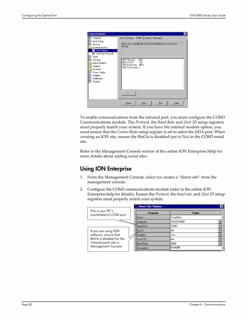
Configuring the Optical Port ION 8000 Series User Guide
Page 82 Chapter 6 - Communications
To enable communications from the infrared port, you must configure the COM3 Communications module. The Protocol, the Baud Rate and Unit ID setup registers must properly match your system. If you have the internal modem option, you must ensure that the Comm Mode setup register is set to select the IrDA port. When creating an ION site, ensure the RtsCts is disabled (set to No) in the COM3 serial site.
Refer to the Management Console section of the online ION Enterprise Help for more details about adding serial sites.
Using ION Enterprise1. From the Management Console, select (or create) a “direct site” from the
management console.
2. Configure the COM3 communications module (refer to the online ION Enterprise help for details). Ensure the Protocol, the baud rate, and Unit ID setup registers must properly match your system.
This is your PC’s (workstation’s) COM port.
If you are using ION software, ensure that RtsCts is disabled for the infrared port's site in Management Console.
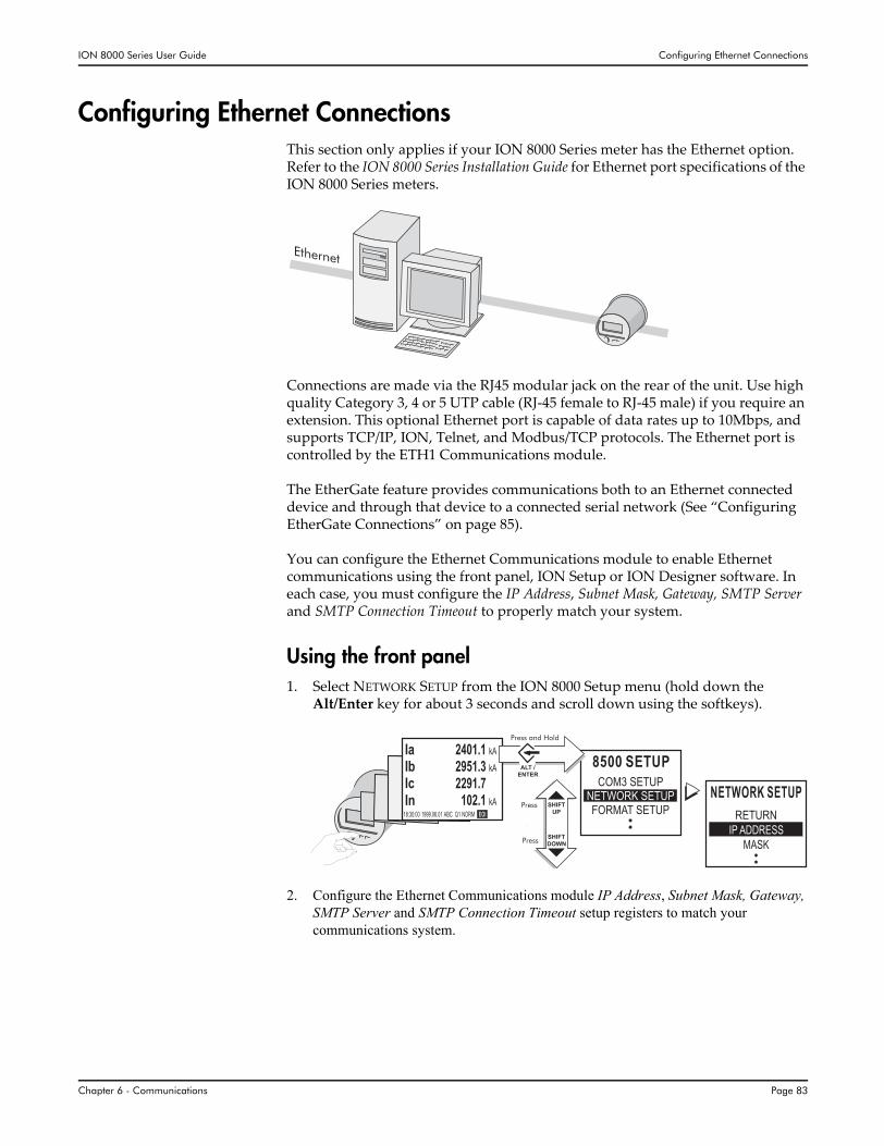
ION 8000 Series User Guide Configuring Ethernet Connections
Chapter 6 - Communications Page 83
Configuring Ethernet ConnectionsThis section only applies if your ION 8000 Series meter has the Ethernet option. Refer to the ION 8000 Series Installation Guide for Ethernet port specifications of the ION 8000 Series meters.
Connections are made via the RJ45 modular jack on the rear of the unit. Use high quality Category 3, 4 or 5 UTP cable (RJ-45 female to RJ-45 male) if you require an extension. This optional Ethernet port is capable of data rates up to 10Mbps, and supports TCP/IP, ION, Telnet, and Modbus/TCP protocols. The Ethernet port is controlled by the ETH1 Communications module.
The EtherGate feature provides communications both to an Ethernet connected device and through that device to a connected serial network (See “Configuring EtherGate Connections” on page 85).
You can configure the Ethernet Communications module to enable Ethernet communications using the front panel, ION Setup or ION Designer software. In each case, you must configure the IP Address, Subnet Mask, Gateway, SMTP Server and SMTP Connection Timeout to properly match your system.
Using the front panel1. Select NETWORK SETUP from the ION 8000 Setup menu (hold down the
Alt/Enter key for about 3 seconds and scroll down using the softkeys).
2. Configure the Ethernet Communications module IP Address, Subnet Mask, Gateway, SMTP Server and SMTP Connection Timeout setup registers to match your communications system.
Ethernet
FORMAT SETUP
8500 SETUP
NETWORK SETUP
MASK
RETURN
IP ADDRESS
COM3 SETUP
NETWORK SETUP
Ia 2401.1 kA
2951.3 kA
2291.7102.1 kA
IbIc
In18:30:00 1999.06.01 ABC Q1 NORM EOI
Press and Hold
Press
Press
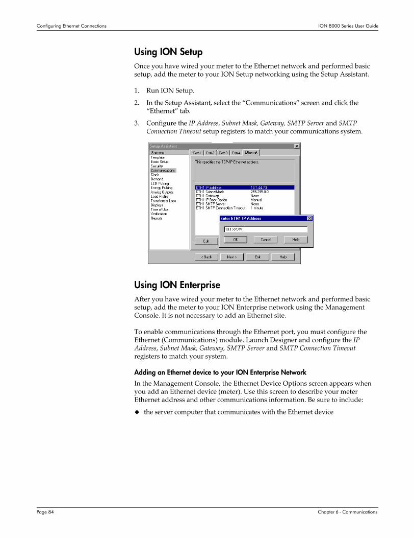
Configuring Ethernet Connections ION 8000 Series User Guide
Page 84 Chapter 6 - Communications
Using ION SetupOnce you have wired your meter to the Ethernet network and performed basic setup, add the meter to your ION Setup networking using the Setup Assistant.
1. Run ION Setup.
2. In the Setup Assistant, select the “Communications” screen and click the “Ethernet” tab.
3. Configure the IP Address, Subnet Mask, Gateway, SMTP Server and SMTP Connection Timeout setup registers to match your communications system.
Using ION EnterpriseAfter you have wired your meter to the Ethernet network and performed basic setup, add the meter to your ION Enterprise network using the Management Console. It is not necessary to add an Ethernet site.
To enable communications through the Ethernet port, you must configure the Ethernet (Communications) module. Launch Designer and configure the IP Address, Subnet Mask, Gateway, SMTP Server and SMTP Connection Timeout registers to match your system.
Adding an Ethernet device to your ION Enterprise Network
In the Management Console, the Ethernet Device Options screen appears when you add an Ethernet device (meter). Use this screen to describe your meter Ethernet address and other communications information. Be sure to include:
the server computer that communicates with the Ethernet device
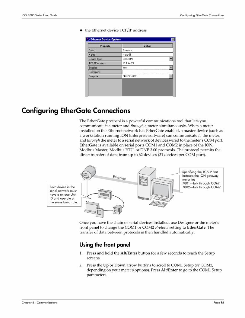
ION 8000 Series User Guide Configuring EtherGate Connections
Chapter 6 - Communications Page 85
the Ethernet device TCP/IP address
Configuring EtherGate ConnectionsThe EtherGate protocol is a powerful communications tool that lets you communicate to a meter and through a meter simultaneously. When a meter installed on the Ethernet network has EtherGate enabled, a master device (such as a workstation running ION Enterprise software) can communicate to the meter, and through the meter to a serial network of devices wired to the meter’s COM port. EtherGate is available on serial ports COM1 and COM2 in place of the ION, Modbus Master, Modbus RTU, or DNP 3.00 protocols. The protocol permits the direct transfer of data from up to 62 devices (31 devices per COM port).
Once you have the chain of serial devices installed, use Designer or the meter’s front panel to change the COM1 or COM2 Protocol setting to EtherGate. The transfer of data between protocols is then handled automatically.
Using the front panel1. Press and hold the Alt/Enter button for a few seconds to reach the Setup
screens.
2. Press the Up or Down arrow buttons to scroll to COM1 Setup (or COM2, depending on your meter’s options). Press Alt/Enter to go to the COM1 Setup parameters.
Ethernet
Specifying the TCP/IP Port instructs the ION gateway meter to:7801—talk through COM17802—talk through COM2 Each device in the
serial network must have a unique Unit ID and operate at the same baud rate.
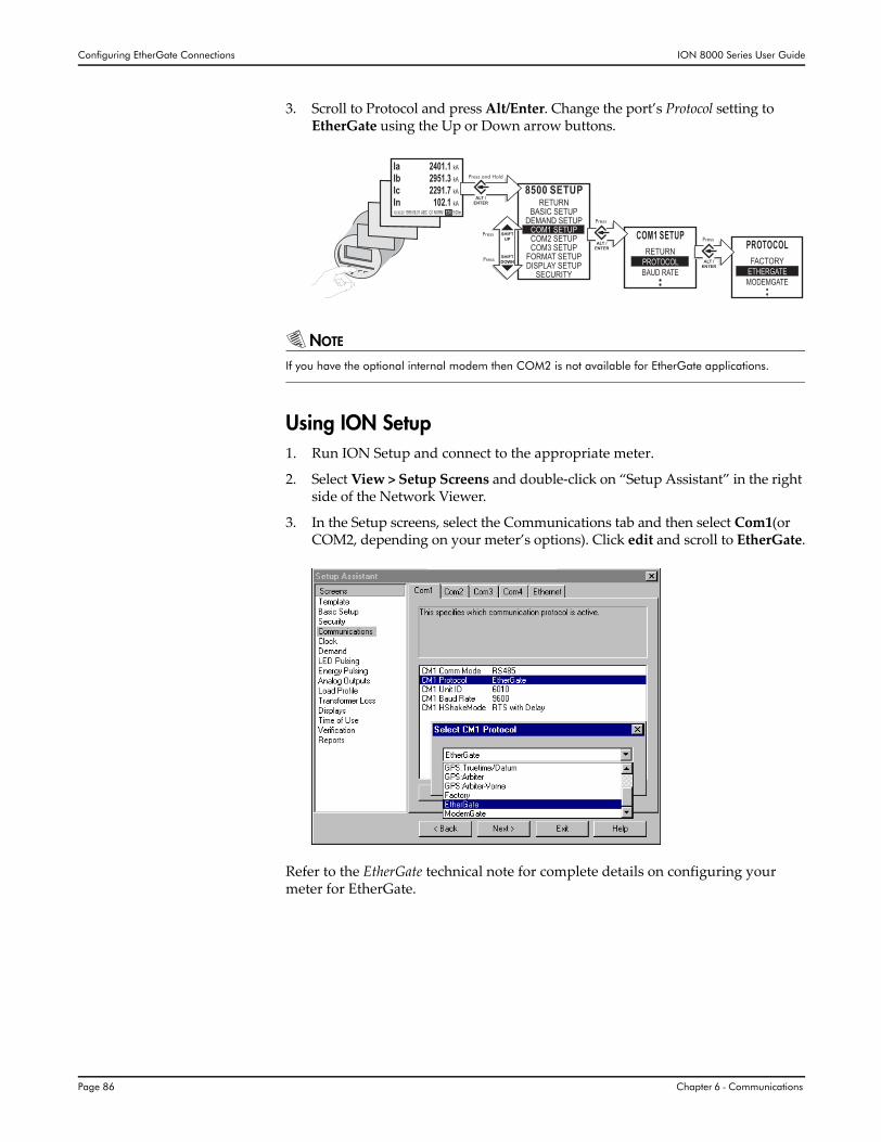
Configuring EtherGate Connections ION 8000 Series User Guide
Page 86 Chapter 6 - Communications
3. Scroll to Protocol and press Alt/Enter. Change the port’s Protocol setting to EtherGate using the Up or Down arrow buttons.
NOTE
If you have the optional internal modem then COM2 is not available for EtherGate applications.
Using ION Setup1. Run ION Setup and connect to the appropriate meter.
2. Select View > Setup Screens and double-click on “Setup Assistant” in the right side of the Network Viewer.
3. In the Setup screens, select the Communications tab and then select Com1(or COM2, depending on your meter’s options). Click edit and scroll to EtherGate.
Refer to the EtherGate technical note for complete details on configuring your meter for EtherGate.
COM1 SETUP
BAUD RATE
RETURN
PROTOCOL
PROTOCOL
MODEMGATE
FACTORY
ETHERGATE
DEMAND SETUP
COM1 SETUP
COM2 SETUP
COM3 SETUP
SECURITY
FORMAT SETUP
DISPLAY SETUP
RETURN
8500 SETUP
BASIC SETUPPress
PressPress
Press
Ia 2401.1 kA
2951.3 kA
2291.7 kA
102.1 kA
IbIcIn18:30:00 1999.06.01 ABC Q1 NORM 5:00mEOI
Press and Hold
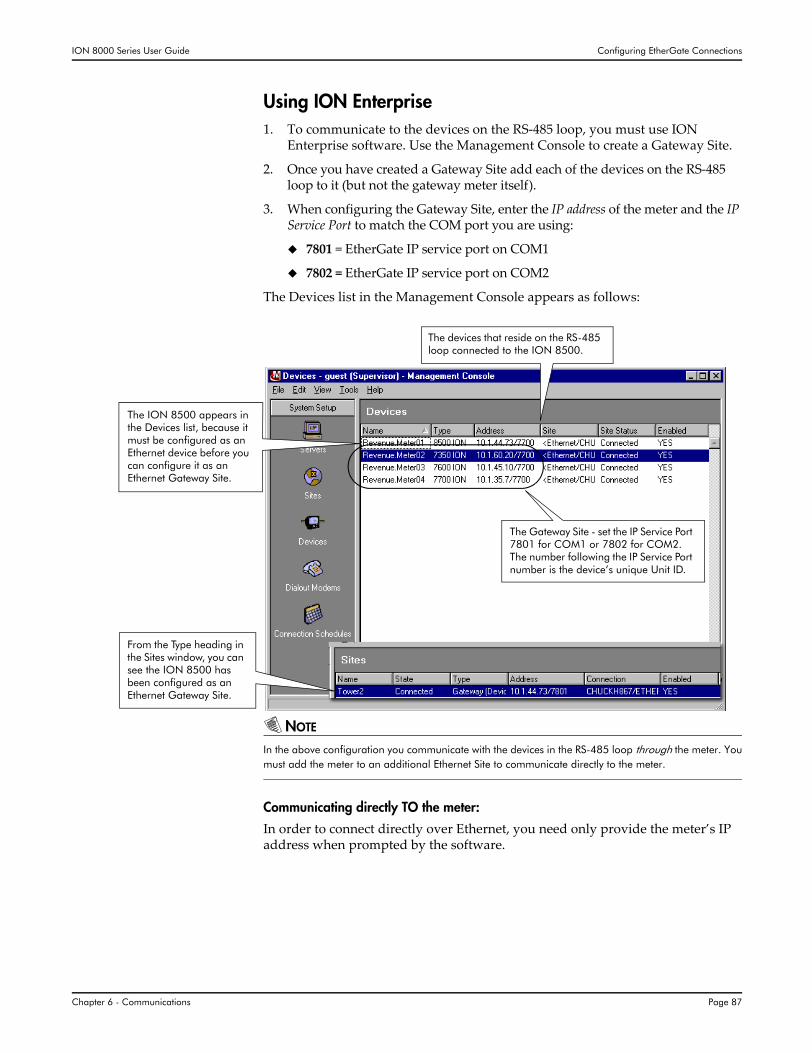
ION 8000 Series User Guide Configuring EtherGate Connections
Chapter 6 - Communications Page 87
Using ION Enterprise1. To communicate to the devices on the RS-485 loop, you must use ION
Enterprise software. Use the Management Console to create a Gateway Site.
2. Once you have created a Gateway Site add each of the devices on the RS-485 loop to it (but not the gateway meter itself).
3. When configuring the Gateway Site, enter the IP address of the meter and the IP Service Port to match the COM port you are using:
7801 = EtherGate IP service port on COM1
7802 = EtherGate IP service port on COM2
The Devices list in the Management Console appears as follows:
NOTE
In the above configuration you communicate with the devices in the RS-485 loop through the meter. Youmust add the meter to an additional Ethernet Site to communicate directly to the meter.
Communicating directly TO the meter:
In order to connect directly over Ethernet, you need only provide the meter’s IP address when prompted by the software.
The devices that reside on the RS-485 loop connected to the ION 8500.
The Gateway Site - set the IP Service Port 7801 for COM1 or 7802 for COM2. The number following the IP Service Port number is the device’s unique Unit ID.
From the Type heading in the Sites window, you can see the ION 8500 has been configured as an Ethernet Gateway Site.
The ION 8500 appears in the Devices list, because it must be configured as an Ethernet device before you can configure it as an Ethernet Gateway Site.
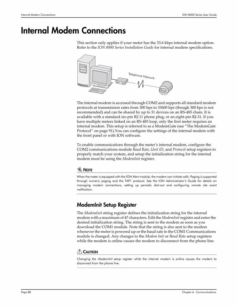
Internal Modem Connections ION 8000 Series User Guide
Page 88 Chapter 6 - Communications
Internal Modem ConnectionsThis section only applies if your meter has the 33.6 kbps internal modem option. Refer to the ION 8000 Series Installation Guide for internal modem specifications.
The internal modem is accessed through COM2 and supports all standard modem protocols at transmission rates from 300 bps to 33600 bps (though 300 bps is not recommended) and can be shared by up to 31 devices on an RS-485 chain. It is available with a standard six-pin RJ-11 phone plug, or an eight-pin RJ-31. If you have multiple meters linked on an RS-485 loop, only the first meter requires an internal modem. This setup is referred to as a ModemGate (see “The ModemGate Protocol” on page 91).You can configure the settings of the internal modem with the front panel or with ION software.
To enable communications through the meter’s internal modem, configure the COM2 communications module Baud Rate, Unit ID, and Protocol setup registers to properly match your system, and setup the initialization string for the internal modem must be using the ModemInit register.
NOTE
When the meter is equipped with the ION Alert module, the modem can initiate calls. Paging is supportedthrough numeric paging and the TAP1 protocol. See the ION Administrator’s Guide for details onmanaging modem connections, setting up periodic dial-out and configuring remote site eventnotification.
ModemInit Setup RegisterThe ModemInit string register defines the initialization string for the internal modem with a maximum of 47 characters. Edit the ModemInit register and enter the desired initialization string. The string is sent to the modem as soon as you download the COM1 module. Note that the string is also sent to the modem whenever the meter is powered up or the baud rate in the COM1 Communications module is changed. Any changes to the Modem Init or Baud Rate setup registers while the modem is online causes the modem to disconnect from the phone line.
CAUTION
Changing the ModemInit setup register while the internal modem is online causes the modem todisconnect from the phone line.
Telephone Network
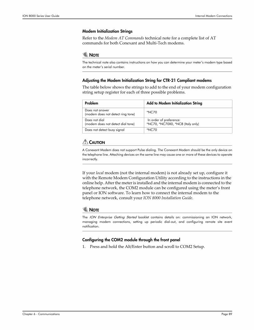
ION 8000 Series User Guide Internal Modem Connections
Chapter 6 - Communications Page 89
Modem Initialization Strings
Refer to the Modem AT Commands technical note for a complete list of AT commands for both Conexant and Multi-Tech modems.
NOTE
The technical note also contains instructions on how you can determine your meter’s modem type basedon the meter’s serial number.
Adjusting the Modem Initialization String for CTR-21 Compliant modems
The table below shows the strings to add to the end of your modem configuration string setup register for each of three possible problems.
CAUTION
A Conexant Modem does not support Pulse dialing. The Conexant Modem should be the only device onthe telephone line. Attaching devices on the same line may cause one or more of these devices to operateincorrectly.
If your local modem (not the internal modem) is not already set up, configure it with the Remote Modem Configuration Utility according to the instructions in the online help. After the meter is installed and the internal modem is connected to the telephone network, the COM2 module can be configured using the meter’s front panel or ION software. To learn how to connect the internal modem to the telephone network, consult your ION 8000 Installation Guide.
NOTE
The ION Enterprise Getting Started booklet contains details on: commissioning an ION network,managing modem connections, setting up periodic dial-out, and configuring remote site eventnotification.
Configuring the COM2 module through the front panel
1. Press and hold the Alt/Enter button and scroll to COM2 Setup.
Problem Add to Modem Initialization String
Does not answer(modem does not detect ring tone) *NC70
Does not dial(modem does not detect dial tone)
In order of preference:*NC70, *NC70X0, *NC8 (Italy only)
Does not detect busy signal *NC70
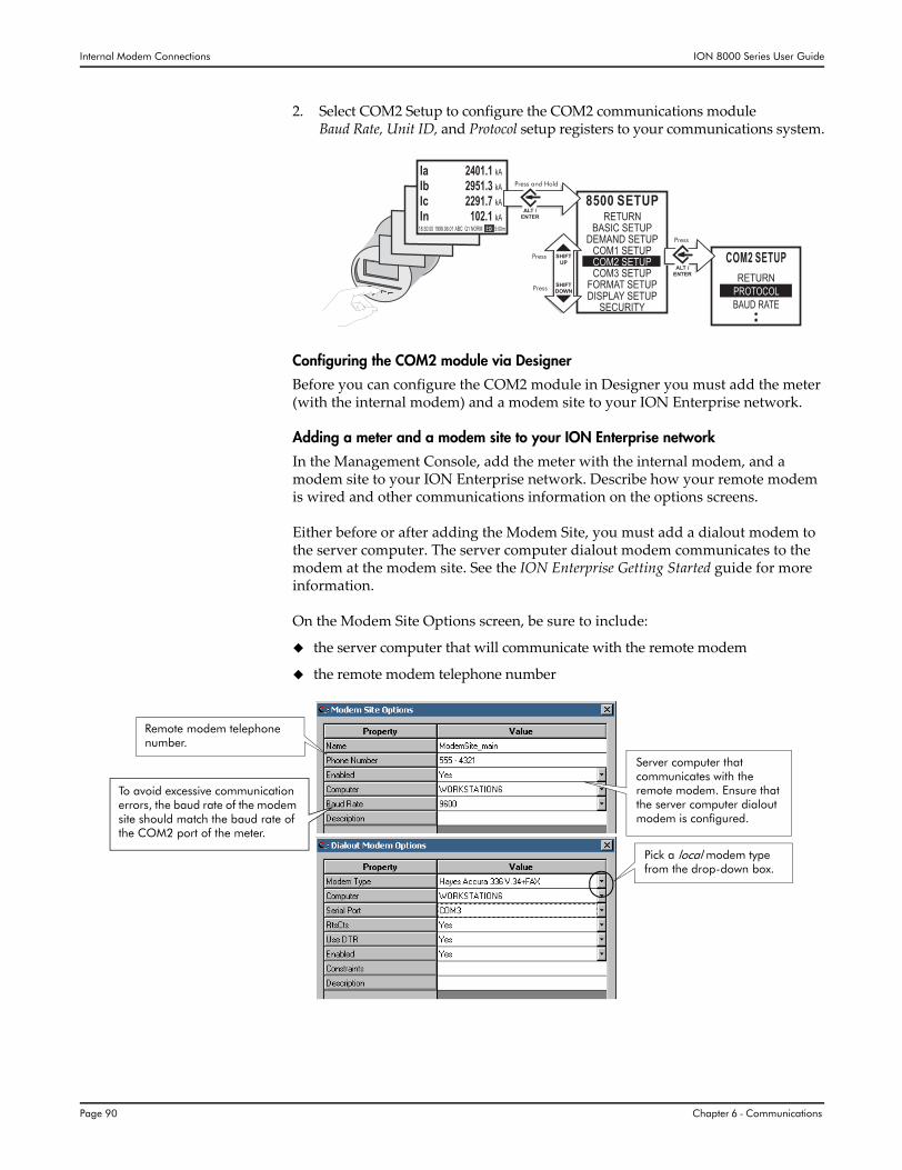
Internal Modem Connections ION 8000 Series User Guide
Page 90 Chapter 6 - Communications
2. Select COM2 Setup to configure the COM2 communications module Baud Rate, Unit ID, and Protocol setup registers to your communications system.
Configuring the COM2 module via Designer
Before you can configure the COM2 module in Designer you must add the meter (with the internal modem) and a modem site to your ION Enterprise network.
Adding a meter and a modem site to your ION Enterprise network
In the Management Console, add the meter with the internal modem, and a modem site to your ION Enterprise network. Describe how your remote modem is wired and other communications information on the options screens.
Either before or after adding the Modem Site, you must add a dialout modem to the server computer. The server computer dialout modem communicates to the modem at the modem site. See the ION Enterprise Getting Started guide for more information.
On the Modem Site Options screen, be sure to include:
the server computer that will communicate with the remote modem
the remote modem telephone number
COM2 SETUP
BAUD RATE
RETURN
PROTOCOL
DEMAND SETUP
COM1 SETUP
COM2 SETUP
COM3 SETUP
SECURITY
FORMAT SETUP
DISPLAY SETUP
RETURN
8500 SETUP
BASIC SETUPPress
Press
Press
Ia 2401.1 kA
2951.3 kA
2291.7 kA
102.1 kA
IbIcIn
18:30:00 1999.06.01 ABC Q1 NORM 5:00mEOI
Press and Hold
To avoid excessive communication errors, the baud rate of the modem site should match the baud rate of the COM2 port of the meter.
Server computer that communicates with the remote modem. Ensure that the server computer dialout modem is configured.
Remote modem telephone number.
Pick a local modem type from the drop-down box.
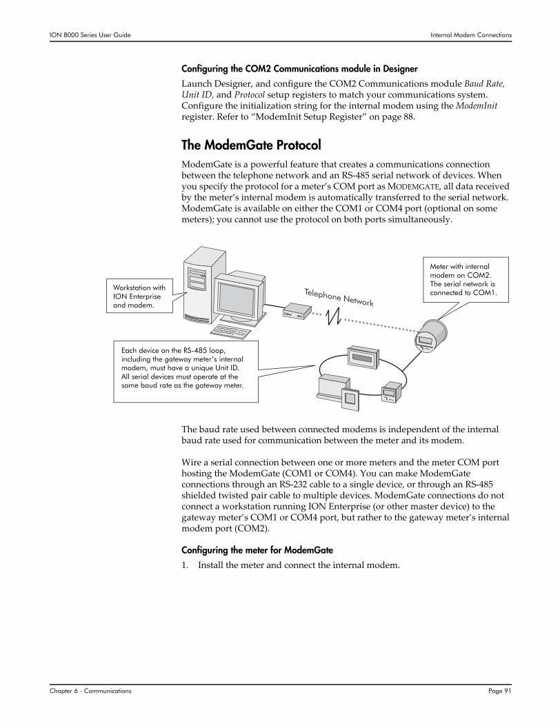
ION 8000 Series User Guide Internal Modem Connections
Chapter 6 - Communications Page 91
Configuring the COM2 Communications module in Designer
Launch Designer, and configure the COM2 Communications module Baud Rate, Unit ID, and Protocol setup registers to match your communications system. Configure the initialization string for the internal modem using the ModemInit register. Refer to “ModemInit Setup Register” on page 88.
The ModemGate ProtocolModemGate is a powerful feature that creates a communications connection between the telephone network and an RS-485 serial network of devices. When you specify the protocol for a meter’s COM port as MODEMGATE, all data received by the meter’s internal modem is automatically transferred to the serial network. ModemGate is available on either the COM1 or COM4 port (optional on some meters); you cannot use the protocol on both ports simultaneously.
The baud rate used between connected modems is independent of the internal baud rate used for communication between the meter and its modem.
Wire a serial connection between one or more meters and the meter COM port hosting the ModemGate (COM1 or COM4). You can make ModemGate connections through an RS-232 cable to a single device, or through an RS-485 shielded twisted pair cable to multiple devices. ModemGate connections do not connect a workstation running ION Enterprise (or other master device) to the gateway meter’s COM1 or COM4 port, but rather to the gateway meter’s internal modem port (COM2).
Configuring the meter for ModemGate
1. Install the meter and connect the internal modem.
Telephone Network
Meter with internal modem on COM2.The serial network is connected to COM1.
Workstation with ION Enterprise and modem.
Each device on the RS-485 loop, including the gateway meter’s internal modem, must have a unique Unit ID.All serial devices must operate at the same baud rate as the gateway meter.
Internal Modem Connections ION 8000 Series User Guide
Page 92 Chapter 6 - Communications
2. Use the front panel or ION software to set up the internal modem and the serial communications port (COM1 or COM4) that is the ModemGate. The default for these ports is:
NOTE
You can enable ModemGate on either COM1 or COM4, not both simultaneously.
3. Set the internal modem COM2 baud rate, Unit ID and protocol. The baud rate must be the same as the port hosting the gateway and all the devices connected to the gateway.
4. Set the protocol of the port hosting the gateway to MODEMGATE (either COM1 or COM4). You must also set the baud rate to the same as the modem baud rate (COM2).
Configuring devices connected to the ModemGate meter
1. Use ION software or the front panel to change and configure settings. Ensure each device connected to the meter has the same baud rate as the meter ModemGate port (either COM1 or COM4).
2. Ensure each device connected on the RS-485 network (including the meter modem) has a unique Unit ID number. Make a record of your changes.
NOTE
In order to configure the dial-in connection the system administrator requires the serial baud rate of themodem site and a record of the Unit ID numbers for every device.
3. Ensure ‘RS-485’ is selected for connections to multiple devices along the same bus.
Adding ModemGate meters to the network
1. Once you have created a Modem Site using the Management Console, add the meter and all devices connected to the ModemGate port.
2. Ensure each meter on the modem Site has a unique Unit ID number (the technician who installed the meter at the remote site should provide you with this information).
Communications modules Setting Default
COM1 (Standard RS-232/485 port)
Comm Mode RS-485
Baud Rate 9600
Unit ID 100
Protocol ION
COM2 (Modem Port)
Baud Rate 9600
Unit ID 101
Protocol ION
Modem Init Strings AT&F
COM4 (Optional dedicated RS-485 port)
Baud Rate 9600
Unit ID 103
Protocol ION

ION 8000 Series User Guide Internal Modem Connections
Chapter 6 - Communications Page 93
Refer to the ModemGate technical note for complete details on configuring your meter for ModemGate.

Page 95
7 Third Party ProtocolsThis chapter explains how Modbus and DNP 3.0 protocols are implemented on the ION 8000 series meter.
In this chapter
Overview . . . . . . . . . . . . . . . . . . . . . . . . . . . . . . . . . . . . . . . . . . . . . . . . . 96Communications Protocol Configuration . . . . . . . . . . . . . . . . . . . . . . . . . . . . . . . . 96
The Meter as Modbus Slave . . . . . . . . . . . . . . . . . . . . . . . . . . . . . . . . . . . 97Using the Modbus RTU Protocol . . . . . . . . . . . . . . . . . . . . . . . . . . . . . . . . . . . . . . . . 97
The Factory Modbus Slave Configuration ......................................................... 97Changing the Modbus Configuration ................................................................ 98
Modbus Slave Modules . . . . . . . . . . . . . . . . . . . . . . . . . . . . . . . . . . . . . . . . . . . . . . . . 98Amp/Freq/Unbal ................................................................................................... 99Volts ....................................................................................................................... 100kW/kVAr/kVA ..................................................................................................... 101kWh/kVArh .......................................................................................................... 102PF/THD/Kfactor ................................................................................................... 103Importing Data using Modbus RTU ................................................................. 103
Using the Modbus/TCP Protocol . . . . . . . . . . . . . . . . . . . . . . . . . . . . . . . . . . . . . . . 104Modbus TCP Communications ......................................................................... 104
The Meter as Modbus Master . . . . . . . . . . . . . . . . . . . . . . . . . . . . . . . . . 105The Factory Modbus Master Configuration .................................................... 105
Configuring Modbus . . . . . . . . . . . . . . . . . . . . . . . . . . . . . . . . . . . . . . . . 106Using the Front Panel ......................................................................................... 106Using ION Setup ................................................................................................. 106
Using the DNP 3.0 Protocol . . . . . . . . . . . . . . . . . . . . . . . . . . . . . . . . . . . 108The Factory DNP 3.0 Configuration ................................................................. 108
Configuring DNP 3.0 . . . . . . . . . . . . . . . . . . . . . . . . . . . . . . . . . . . . . . . . . . . . . . . . . 108Using the Front Panel ......................................................................................... 109Using ION Setup ................................................................................................. 109
Overview ION 8000 Series User Guide
Page 96 Chapter 7 - Third Party Protocols
OverviewION 8000 series meters support DNP 3.0, Modbus RTU and Modbus/TCP protocols.
While your meter is factory configured to send data (acting as Modbus Slave), it is not ready to receive data as a Modbus Master until you set up the necessary framework. The meter is also pre-configured to send DNP 3.0 data to a DNP Master.
NOTE
Changing the default factory third-party protocol frameworks (or creating new frameworks to enablereceive functionality) is an advanced procedure. Refer to the DNP modules and Modbus modulesdescriptions in the ION Reference, as well as the technical notes Multiport DNP 3.0 and ION Technology,and Modbus and ION Technology before proceeding.
Most Modbus and DNP modules on the meter are factory pre-set and only require basic configuration, such as communications setup.
NOTE
Changing these modules from their factory configuration is an advanced setup procedure that requiresan understanding of the protocol, as well as an understanding of the meter’s internal operation. For moreinformation on your meter and these protocols see the Common Modbus Registers document and theION 8000 Series DNP 3.0 Device Profile.
Communications Protocol ConfigurationIn order to use the factory Modbus or DNP configuration, you must first assign the communications channel you want to use. By default, all communications ports are configured to use the ION protocol. Choose the 3rd-party protocol you want from the list of available protocols in the Communications module’s Protocol setup register. See the Communications chapter for instructions.
NOTE
Modbus RTU is available on each of the meter’s communications ports, and multiple ports cancommunicate using Modbus simultaneously. Up to three ports can use the DNP 3.00 protocol at any onetime.
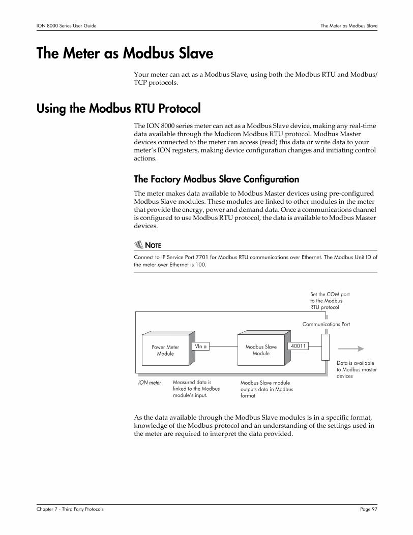
ION 8000 Series User Guide The Meter as Modbus Slave
Chapter 7 - Third Party Protocols Page 97
The Meter as Modbus SlaveYour meter can act as a Modbus Slave, using both the Modbus RTU and Modbus/TCP protocols.
Using the Modbus RTU ProtocolThe ION 8000 series meter can act as a Modbus Slave device, making any real-time data available through the Modicon Modbus RTU protocol. Modbus Master devices connected to the meter can access (read) this data or write data to your meter’s ION registers, making device configuration changes and initiating control actions.
The Factory Modbus Slave ConfigurationThe meter makes data available to Modbus Master devices using pre-configured Modbus Slave modules. These modules are linked to other modules in the meter that provide the energy, power and demand data. Once a communications channel is configured to use Modbus RTU protocol, the data is available to Modbus Master devices.
NOTE
Connect to IP Service Port 7701 for Modbus RTU communications over Ethernet. The Modbus Unit ID ofthe meter over Ethernet is 100.
As the data available through the Modbus Slave modules is in a specific format, knowledge of the Modbus protocol and an understanding of the settings used in the meter are required to interpret the data provided.
ION meter
Modbus SlaveModule
Power MeterModule
Measured data islinked to the Modbusmodule’s input.
Modbus Slave moduleoutputs data in Modbusformat
Data is availableto Modbus masterdevices
Set the COM portto the ModbusRTU protocol
Vln a 40011
Communications Port
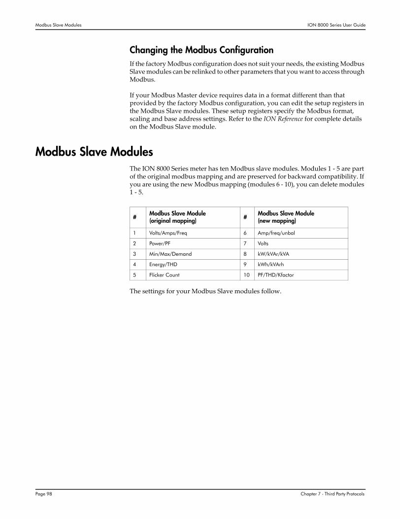
Modbus Slave Modules ION 8000 Series User Guide
Page 98 Chapter 7 - Third Party Protocols
Changing the Modbus ConfigurationIf the factory Modbus configuration does not suit your needs, the existing Modbus Slave modules can be relinked to other parameters that you want to access through Modbus.
If your Modbus Master device requires data in a format different than that provided by the factory Modbus configuration, you can edit the setup registers in the Modbus Slave modules. These setup registers specify the Modbus format, scaling and base address settings. Refer to the ION Reference for complete details on the Modbus Slave module.
Modbus Slave ModulesThe ION 8000 Series meter has ten Modbus slave modules. Modules 1 - 5 are part of the original modbus mapping and are preserved for backward compatibility. If you are using the new Modbus mapping (modules 6 - 10), you can delete modules 1 - 5.
The settings for your Modbus Slave modules follow.
# Modbus Slave Module (original mapping) # Modbus Slave Module
(new mapping)
1 Volts/Amps/Freq 6 Amp/freq/unbal
2 Power/PF 7 Volts
3 Min/Max/Demand 8 kW/kVAr/kVA
4 Energy/THD 9 kWh/kVArh
5 Flicker Count 10 PF/THD/Kfactor
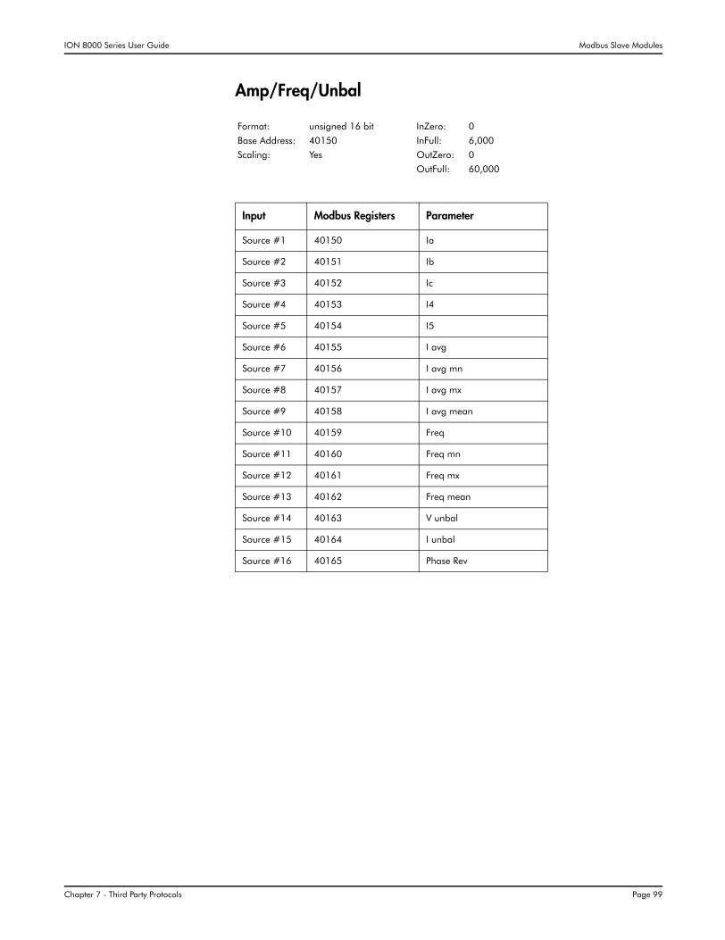
ION 8000 Series User Guide Modbus Slave Modules
Chapter 7 - Third Party Protocols Page 99
Amp/Freq/Unbal
Format: unsigned 16 bit InZero: 0
Base Address: 40150 InFull: 6,000
Scaling: Yes OutZero: 0
OutFull: 60,000
Input Modbus Registers Parameter
Source #1 40150 Ia
Source #2 40151 Ib
Source #3 40152 Ic
Source #4 40153 I4
Source #5 40154 I5
Source #6 40155 I avg
Source #7 40156 I avg mn
Source #8 40157 I avg mx
Source #9 40158 I avg mean
Source #10 40159 Freq
Source #11 40160 Freq mn
Source #12 40161 Freq mx
Source #13 40162 Freq mean
Source #14 40163 V unbal
Source #15 40164 I unbal
Source #16 40165 Phase Rev
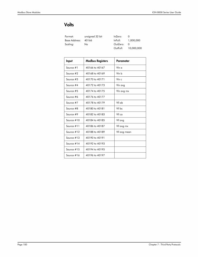
Modbus Slave Modules ION 8000 Series User Guide
Page 100 Chapter 7 - Third Party Protocols
Volts
Format: unsigned 32 bit InZero: 0
Base Address: 40166 InFull: 1,000,000
Scaling: No OutZero: 0
OutFull: 10,000,000
Input Modbus Registers Parameter
Source #1 40166 to 40167 Vln a
Source #2 40168 to 40169 Vln b
Source #3 40170 to 40171 Vln c
Source #4 40172 to 40173 Vln avg
Source #5 40174 to 40175 Vln avg mx
Source #6 40176 to 40177
Source #7 40178 to 40179 Vll ab
Source #8 40180 to 40181 Vll bc
Source #9 40182 to 40183 Vll ca
Source #10 40184 to 40185 Vll avg
Source #11 40186 to 40187 Vll avg mx
Source #12 40188 to 40189 Vll avg mean
Source #13 40190 to 40191
Source #14 40192 to 40193
Source #15 40194 to 40195
Source #16 40196 to 40197
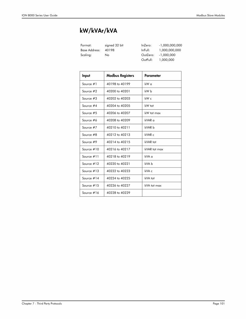
ION 8000 Series User Guide Modbus Slave Modules
Chapter 7 - Third Party Protocols Page 101
kW/kVAr/kVA
Format: signed 32 bit InZero: -1,000,000,000
Base Address: 40198 InFull: 1,000,000,000
Scaling: No OutZero: -1,000,000
OutFull: 1,000,000
Input Modbus Registers Parameter
Source #1 40198 to 40199 kW a
Source #2 40200 to 40201 kW b
Source #3 40202 to 40203 kW c
Source #4 40204 to 40205 kW tot
Source #5 40206 to 40207 kW tot max
Source #6 40208 to 40209 kVAR a
Source #7 40210 to 40211 kVAR b
Source #8 40212 to 40213 kVAR c
Source #9 40214 to 40215 kVAR tot
Source #10 40216 to 40217 kVAR tot max
Source #11 40218 to 40219 kVA a
Source #12 40220 to 40221 kVA b
Source #13 40222 to 40223 kVA c
Source #14 40224 to 40225 kVA tot
Source #15 40226 to 40227 kVA tot max
Source #16 40228 to 40229
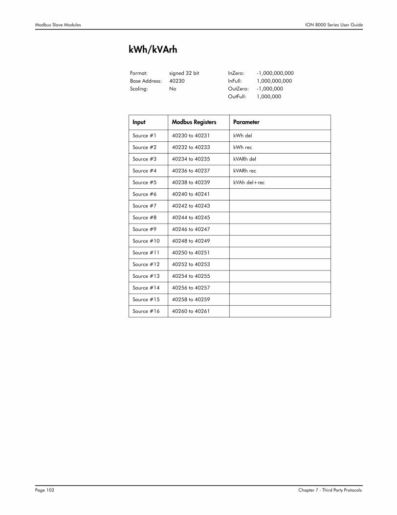
Modbus Slave Modules ION 8000 Series User Guide
Page 102 Chapter 7 - Third Party Protocols
kWh/kVArh
Format: signed 32 bit InZero: -1,000,000,000
Base Address: 40230 InFull: 1,000,000,000
Scaling: No OutZero: -1,000,000
OutFull: 1,000,000
Input Modbus Registers Parameter
Source #1 40230 to 40231 kWh del
Source #2 40232 to 40233 kWh rec
Source #3 40234 to 40235 kVARh del
Source #4 40236 to 40237 kVARh rec
Source #5 40238 to 40239 kVAh del+rec
Source #6 40240 to 40241
Source #7 40242 to 40243
Source #8 40244 to 40245
Source #9 40246 to 40247
Source #10 40248 to 40249
Source #11 40250 to 40251
Source #12 40252 to 40253
Source #13 40254 to 40255
Source #14 40256 to 40257
Source #15 40258 to 40259
Source #16 40260 to 40261
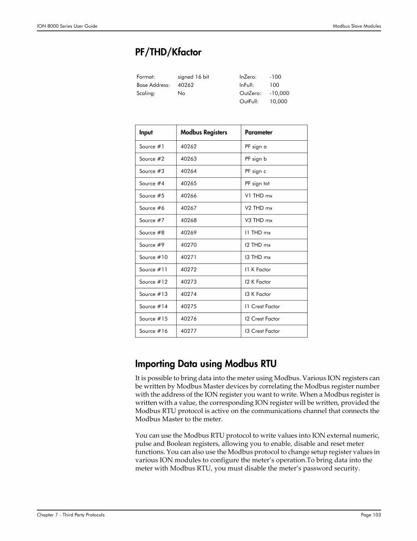
ION 8000 Series User Guide Modbus Slave Modules
Chapter 7 - Third Party Protocols Page 103
PF/THD/Kfactor
Importing Data using Modbus RTUIt is possible to bring data into the meter using Modbus. Various ION registers can be written by Modbus Master devices by correlating the Modbus register number with the address of the ION register you want to write. When a Modbus register is written with a value, the corresponding ION register will be written, provided the Modbus RTU protocol is active on the communications channel that connects the Modbus Master to the meter.
You can use the Modbus RTU protocol to write values into ION external numeric, pulse and Boolean registers, allowing you to enable, disable and reset meter functions. You can also use the Modbus protocol to change setup register values in various ION modules to configure the meter’s operation.To bring data into the meter with Modbus RTU, you must disable the meter’s password security.
Format: signed 16 bit InZero: -100
Base Address: 40262 InFull: 100
Scaling: No OutZero: -10,000
OutFull: 10,000
Input Modbus Registers Parameter
Source #1 40262 PF sign a
Source #2 40263 PF sign b
Source #3 40264 PF sign c
Source #4 40265 PF sign tot
Source #5 40266 V1 THD mx
Source #6 40267 V2 THD mx
Source #7 40268 V3 THD mx
Source #8 40269 I1 THD mx
Source #9 40270 I2 THD mx
Source #10 40271 I3 THD mx
Source #11 40272 I1 K Factor
Source #12 40273 I2 K Factor
Source #13 40274 I3 K Factor
Source #14 40275 I1 Crest Factor
Source #15 40276 I2 Crest Factor
Source #16 40277 I3 Crest Factor
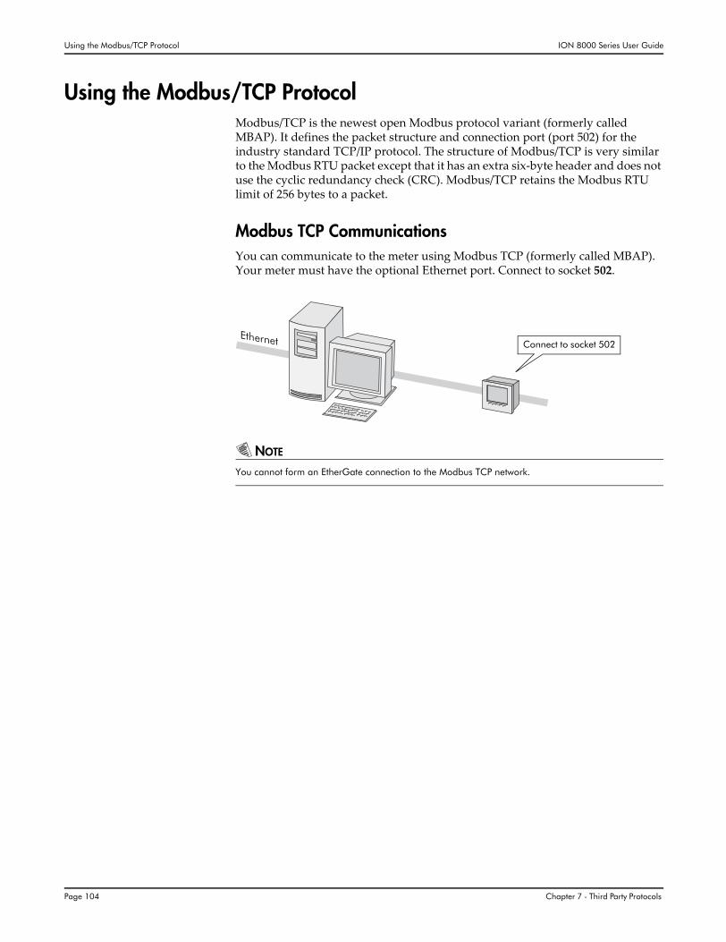
Using the Modbus/TCP Protocol ION 8000 Series User Guide
Page 104 Chapter 7 - Third Party Protocols
Using the Modbus/TCP ProtocolModbus/TCP is the newest open Modbus protocol variant (formerly called MBAP). It defines the packet structure and connection port (port 502) for the industry standard TCP/IP protocol. The structure of Modbus/TCP is very similar to the Modbus RTU packet except that it has an extra six-byte header and does not use the cyclic redundancy check (CRC). Modbus/TCP retains the Modbus RTU limit of 256 bytes to a packet.
Modbus TCP CommunicationsYou can communicate to the meter using Modbus TCP (formerly called MBAP). Your meter must have the optional Ethernet port. Connect to socket 502.
NOTE
You cannot form an EtherGate connection to the Modbus TCP network.
Ethernet Connect to socket 502
ION 8000 Series User Guide The Meter as Modbus Master
Chapter 7 - Third Party Protocols Page 105
The Meter as Modbus MasterYour meter can act as a Modbus Master using the Modbus RTU and Modbus/TCP protocols.
The ION meter acting as Modbus Master can write data to (export), and read data from (import) Modbus Slave devices, using various ION modules. The data can be processed by the meter and sent out using other communications methods (email, ION software, etc.). The meter can also send control commands or data directly to other devices on a Modbus network.
The Factory Modbus Master ConfigurationThere is no pre-configured framework for Modbus mastering on your meter. Your meter’s template contains Modbus Import modules that can read values and Modbus Export modules that can write data but they must be enabled and configured in a framework first.
See the Modbus and ION Technology technical for more information on Modbus Master configuration for your meter.
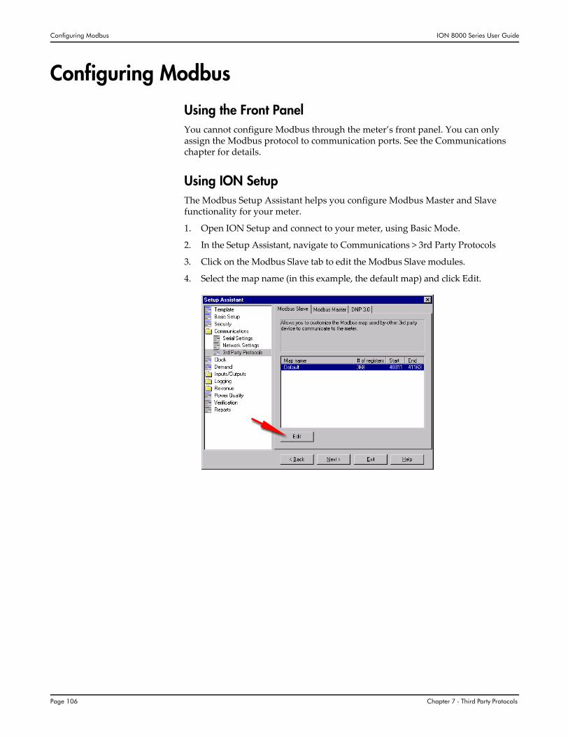
Configuring Modbus ION 8000 Series User Guide
Page 106 Chapter 7 - Third Party Protocols
Configuring Modbus
Using the Front PanelYou cannot configure Modbus through the meter’s front panel. You can only assign the Modbus protocol to communication ports. See the Communications chapter for details.
Using ION SetupThe Modbus Setup Assistant helps you configure Modbus Master and Slave functionality for your meter.
1. Open ION Setup and connect to your meter, using Basic Mode.
2. In the Setup Assistant, navigate to Communications > 3rd Party Protocols
3. Click on the Modbus Slave tab to edit the Modbus Slave modules.
4. Select the map name (in this example, the default map) and click Edit.
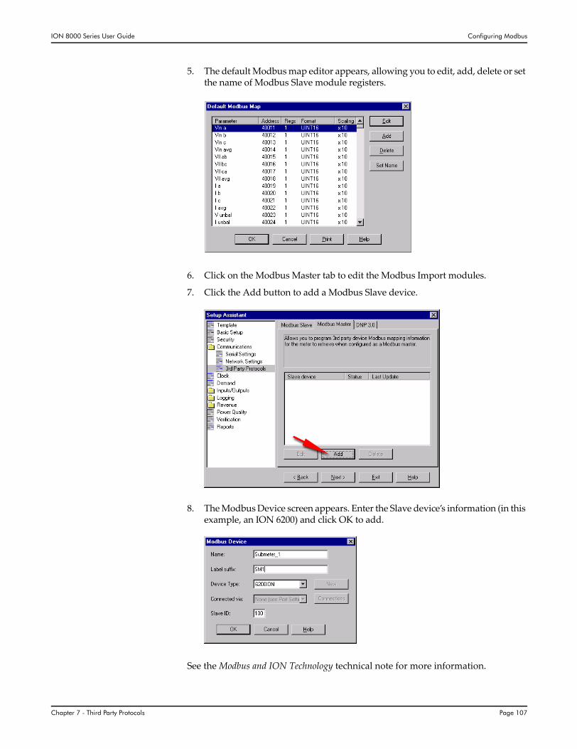
ION 8000 Series User Guide Configuring Modbus
Chapter 7 - Third Party Protocols Page 107
5. The default Modbus map editor appears, allowing you to edit, add, delete or set the name of Modbus Slave module registers.
6. Click on the Modbus Master tab to edit the Modbus Import modules.
7. Click the Add button to add a Modbus Slave device.
8. The Modbus Device screen appears. Enter the Slave device’s information (in this example, an ION 6200) and click OK to add.
See the Modbus and ION Technology technical note for more information.
Using the DNP 3.0 Protocol ION 8000 Series User Guide
Page 108 Chapter 7 - Third Party Protocols
Using the DNP 3.0 ProtocolThe Distributed Network Protocol Version 3.0 (DNP 3.0) is an open protocol used in the electric utility industry for communications and interoperability among substation computers, Remote Terminal Units (RTUs), Intelligent Electronic Devices (IEDs, e.g. meters), and Master Stations.
You meter can be integrated into a DNP network as a DNP Slave, using the DNP Slave Import, DNP Slave Export and DNP Slave Options modules. For more information on the various DNP modules, see the ION Reference.
Your meter supports a maximum of three concurrent connections (or “sessions”) using the DNP 3.0 protocol; one for each serial port, up to three using Ethernet, or a combination of both. Combinations available will depend on the meter's communications options. A session consists of all incoming and outgoing DNP Master/Slave traffic on one of the meter's communications ports.
Consult the DNP User’s Group at http://www.dnp.org/ to learn more about the protocol.
The Factory DNP 3.0 ConfigurationYour meter is pre-configured with a DNP framework that allows for basic DNP Slave functionality. DNP Slave Export modules are used to send data to the DNP Master while DNP Slave Options modules provide per-session settings such as communications options. Although some minor setup of the framework is necessary before it becomes enabled (assigning the DNP protocol to the communications ports etc.), most module settings should not require alteration.
For information on your meter’s default DNP map and factory configuration, see the ION 8000 Series DNP 3.0 Device Profile.
Importing Data using DNP 3.0
Data can be imported into the meter from a DNP control relay or analog output device. DNP Slave Import modules are used to take a DNP Analog output or Binary output object and map them into ION registers.
NOTE
DNP Slave Import modules are not part of the factory DNP framework and must be added manually.Refer to the DNP Slave Import module description in the ION Reference for details.
Configuring DNP 3.0If the factory DNP configuration does not suit your needs, you can relink the existing DNP Slave Export modules to access a different set of parameters through DNP. Alternately, you can add additional DNP Slave Export modules and link the desired ION parameters to them.
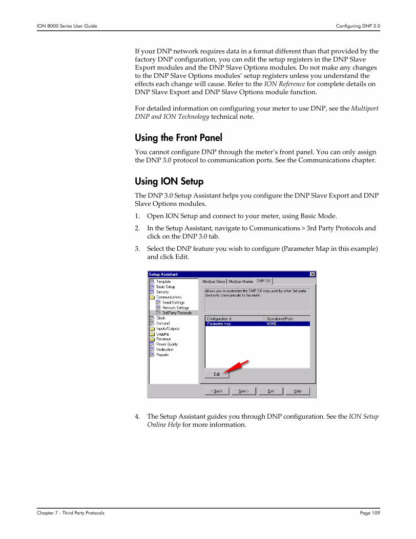
ION 8000 Series User Guide Configuring DNP 3.0
Chapter 7 - Third Party Protocols Page 109
If your DNP network requires data in a format different than that provided by the factory DNP configuration, you can edit the setup registers in the DNP Slave Export modules and the DNP Slave Options modules. Do not make any changes to the DNP Slave Options modules’ setup registers unless you understand the effects each change will cause. Refer to the ION Reference for complete details on DNP Slave Export and DNP Slave Options module function.
For detailed information on configuring your meter to use DNP, see the Multiport DNP and ION Technology technical note.
Using the Front PanelYou cannot configure DNP through the meter’s front panel. You can only assign the DNP 3.0 protocol to communication ports. See the Communications chapter.
Using ION SetupThe DNP 3.0 Setup Assistant helps you configure the DNP Slave Export and DNP Slave Options modules.
1. Open ION Setup and connect to your meter, using Basic Mode.
2. In the Setup Assistant, navigate to Communications > 3rd Party Protocols and click on the DNP 3.0 tab.
3. Select the DNP feature you wish to configure (Parameter Map in this example) and click Edit.
4. The Setup Assistant guides you through DNP configuration. See the ION Setup Online Help for more information.

Page 111
8 TimeThis chapter covers the meter’s clock and time synchronization. For information on IRIG-B GPS time synchronization, see the IRIG-B GPS Time Synchronization product option document.
In this chapter
Meter Clock Configuration . . . . . . . . . . . . . . . . . . . . . . . . . . . . . . . . . . . 112Configuring the Meter Clock . . . . . . . . . . . . . . . . . . . . . . . . . . . . . . . . . . . . . . . . . . 112
Using the Front Panel ......................................................................................... 112Using ION Setup ................................................................................................. 112Using Designer .................................................................................................... 113
Clock Module Settings . . . . . . . . . . . . . . . . . . . . . . . . . . . . . . . . . . . . . . . . . . . . . . . 113
Time Synchronization . . . . . . . . . . . . . . . . . . . . . . . . . . . . . . . . . . . . . . . 114
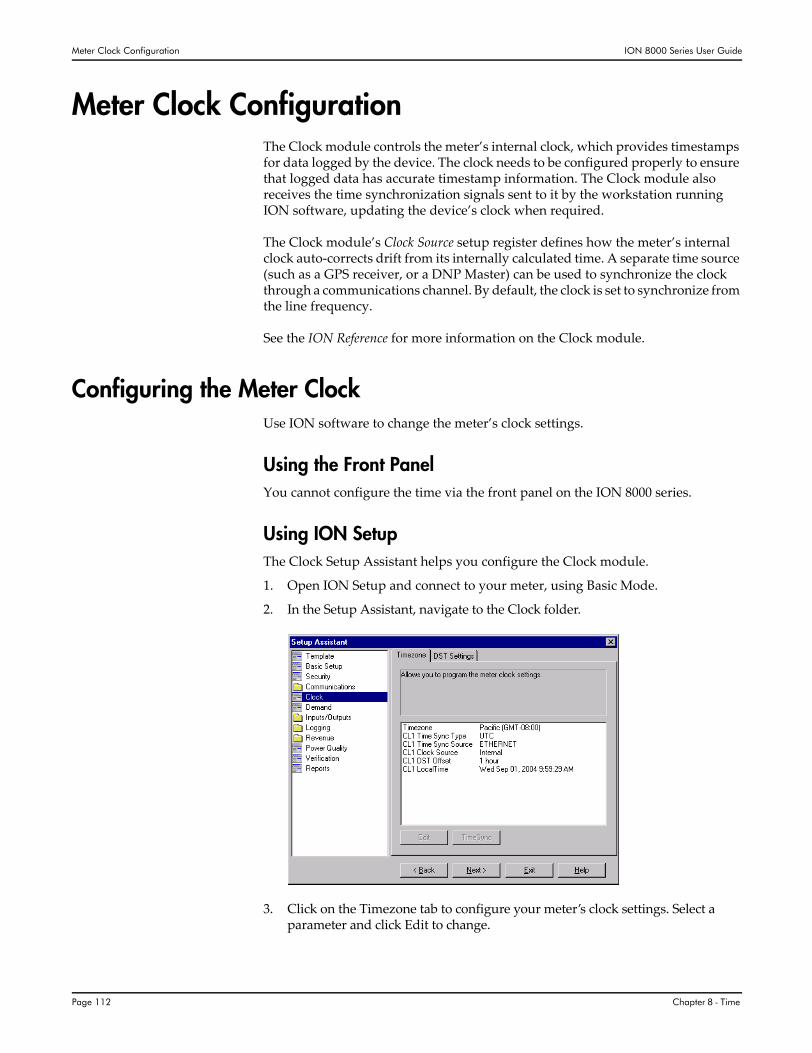
Meter Clock Configuration ION 8000 Series User Guide
Page 112 Chapter 8 - Time
Meter Clock ConfigurationThe Clock module controls the meter’s internal clock, which provides timestamps for data logged by the device. The clock needs to be configured properly to ensure that logged data has accurate timestamp information. The Clock module also receives the time synchronization signals sent to it by the workstation running ION software, updating the device’s clock when required.
The Clock module’s Clock Source setup register defines how the meter’s internal clock auto-corrects drift from its internally calculated time. A separate time source (such as a GPS receiver, or a DNP Master) can be used to synchronize the clock through a communications channel. By default, the clock is set to synchronize from the line frequency.
See the ION Reference for more information on the Clock module.
Configuring the Meter ClockUse ION software to change the meter’s clock settings.
Using the Front PanelYou cannot configure the time via the front panel on the ION 8000 series.
Using ION SetupThe Clock Setup Assistant helps you configure the Clock module.
1. Open ION Setup and connect to your meter, using Basic Mode.
2. In the Setup Assistant, navigate to the Clock folder.
3. Click on the Timezone tab to configure your meter’s clock settings. Select a parameter and click Edit to change.
ION 8000 Series User Guide Clock Module Settings
Chapter 8 - Time Page 113
4. Click on the DST Settings tab to configure your meter’s daylight savings periods for up to 20 years. Select a parameter and click Edit to change.
Using DesignerOpen your meter in Designer and navigate to the Meter Clock Setup framework. Right-click on the Clock module to edit.
Clock Module SettingsThe setup registers in the Clock module specify timezone and Daylight Savings Time (DST) parameters and time synchronization functions.
TIP
When modifying setup registers of the Clock module in Designer, use the Format option to convert between UNIX and conventional time. Refer to the description of the Clock module in the online ION Reference for more details.
Typically, the DST Start and DST End registers do not have to be reconfigured. The factory defaults are the DST start and end dates for 20 years, in UNIX time (the number of seconds since 00:00:00 UTC on Jan. 1, 1970).
Refer to the technical note Time Synchronization and Timekeeping for further details on using the meter’s time synchronization functions.
Setup Register Function Default
TZ Offset Sets the timezone the device is in, relative to Greenwich Mean Time. 0
DST Start 1 …DST Start 20 The date and time when DST begins for 20 separate years. Refer to the ION Device Templates at
www.pwrm.com for the DST Start and DST End defaults for the twenty separate years.
DST End …DST End 20
The date and time when DST ends for 20 separate years.
DST Offset The amount of time the clock is changed when DST begins or ends. 3, 600 seconds
Time Sync Source Specifies the communications port that receives time sync signals. COM3
Time Sync Type Specifies the type of time sync signal (Local or Universal time). UTC
Clock Source Specifies the clock’s time synchronization signal source (line frequency, communications signals, or internal crystal).
Line Frequency
Time Synchronization ION 8000 Series User Guide
Page 114 Chapter 8 - Time
Time SynchronizationTime synchronization lets you synchronize your meter’s internal clock with all of the other meters, devices, and software in a network. Once synchronized, all data logs have timestamps that are relative to a uniform time base. This allows you to achieve precise sequence-of-events and power quality analyses. Use ION software to broadcast time signals across the network, or utilize an external source (such as an NTP server or DNP Master) to synchronize your meter’s clock.
Refer to the technical note Time Synchronization & Timekeeping for more information on implementing time synchronization.
For information on IRIG-B GPS time synchronization, see the IRIG-B GPS Time Synchronization product option document.
Page 115
9 DemandThis chapter explains how to configure and view demand values on your meter.
In this chapter
Introduction . . . . . . . . . . . . . . . . . . . . . . . . . . . . . . . . . . . . . . . . . . . . . . 116
Configuring Demand . . . . . . . . . . . . . . . . . . . . . . . . . . . . . . . . . . . . . . . 116Using the Front Panel ......................................................................................... 116Using ION Setup ................................................................................................. 116Using Designer .................................................................................................... 117
Sliding Window Demand Module Settings . . . . . . . . . . . . . . . . . . . . . . . . . . . . . . 117Thermal Demand Module Settings . . . . . . . . . . . . . . . . . . . . . . . . . . . . . . . . . . . . . 118
Demand Forgiveness . . . . . . . . . . . . . . . . . . . . . . . . . . . . . . . . . . . . . . . 119Additional Information ...................................................................................... 121
Configuring Demand Forgiveness . . . . . . . . . . . . . . . . . . . . . . . . . . . . . . . . . . . . . . 122Using the Front Panel ......................................................................................... 122Using ION Setup ................................................................................................. 122
Introduction ION 8000 Series User Guide
Page 116 Chapter 9 - Demand
IntroductionDemand is a measure of average power consumption over a fixed time interval. Peak (or maximum) demand is the highest demand level recorded over the billing period. Two methods of measuring demand are with Thermal Demand modules and Sliding Window Demand modules. These modules are configured to calculate the average current demand and kW, kVAR and kVA demand. The setup registers in the demand modules define time intervals for demand calculations, setting the sensitivity of the module’s operation.
See the ION Reference for more information about these modules.
Configuring DemandUse ION software to change your meter’s demand settings.
Using the Front Panel1. Press and hold the Alt/Enter button for a few seconds to access the Setup
Menu.
2. Scroll using the Up or Down arrow buttons to select Demand Setup. Press the Alt/Enter button to access Demand Setup parameters.
3. Scroll to the desired parameters using the Up or Down arrow buttons. Press the Alt/Enter button to access each parameter.
Use the Up or Down buttons to edit the value of each parameter.
NOTE
You may be prompted for the meter’s password the first time you attempt to change any values.
4. Select Yes to confirm the change.
Using ION SetupThe Demand Setup Assistant helps you configure Sliding Window Demand only. This screen also contains two registers used for configuring Sliding Window Demand while the meter is in TEST Mode.
1. Open ION Setup and connect to your meter, using Basic Mode.
2. In the Setup Assistant, navigate to the Demand folder.
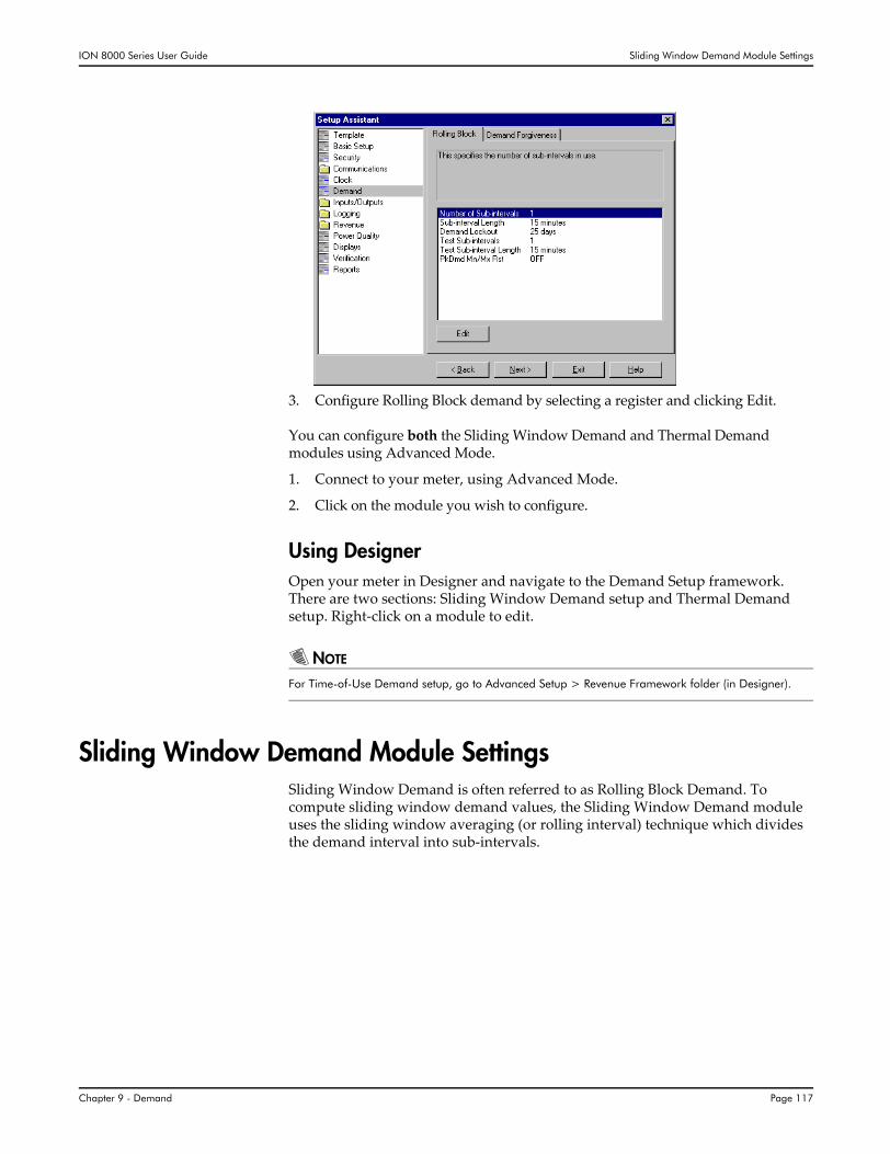
ION 8000 Series User Guide Sliding Window Demand Module Settings
Chapter 9 - Demand Page 117
3. Configure Rolling Block demand by selecting a register and clicking Edit.
You can configure both the Sliding Window Demand and Thermal Demand modules using Advanced Mode.
1. Connect to your meter, using Advanced Mode.
2. Click on the module you wish to configure.
Using DesignerOpen your meter in Designer and navigate to the Demand Setup framework. There are two sections: Sliding Window Demand setup and Thermal Demand setup. Right-click on a module to edit.
NOTE
For Time-of-Use Demand setup, go to Advanced Setup > Revenue Framework folder (in Designer).
Sliding Window Demand Module SettingsSliding Window Demand is often referred to as Rolling Block Demand. To compute sliding window demand values, the Sliding Window Demand module uses the sliding window averaging (or rolling interval) technique which divides the demand interval into sub-intervals.
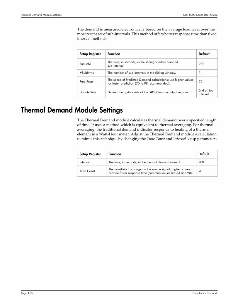
Thermal Demand Module Settings ION 8000 Series User Guide
Page 118 Chapter 9 - Demand
The demand is measured electronically based on the average load level over the most recent set of sub-intervals. This method offers better response time than fixed interval methods.
Thermal Demand Module SettingsThe Thermal Demand module calculates thermal demand over a specified length of time. It uses a method which is equivalent to thermal averaging. For thermal averaging, the traditional demand indicator responds to heating of a thermal element in a Watt-Hour meter. Adjust the Thermal Demand module's calculation to mimic this technique by changing the Time Const and Interval setup parameters.
Setup Register Function Default
Sub IntvlThe time, in seconds, in the sliding window demand sub-interval. 900
#SubIntvls The number of sub-intervals in the sliding window. 1
Pred Resp The speed of Predicted Demand calculations; use higher values for faster prediction (70 to 99 recommended). 70
Update Rate Defines the update rate of the SWinDemand output register End of Sub-Interval
Setup Register Function Default
Interval The time, in seconds, in the thermal demand interval. 900
Time Const The sensitivity to changes in the source signal; higher values provide faster response time (common values are 63 and 90).
90
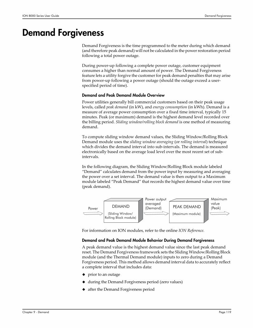
ION 8000 Series User Guide Demand Forgiveness
Chapter 9 - Demand Page 119
Demand ForgivenessDemand Forgiveness is the time programmed to the meter during which demand (and therefore peak demand) will not be calculated in the power restoration period following a total power outage.
During power-up following a complete power outage, customer equipment consumes a higher than normal amount of power. The Demand Forgiveness feature lets a utility forgive the customer for peak demand penalties that may arise from power-up following a power outage (should the outage exceed a user-specified period of time).
Demand and Peak Demand Module Overview
Power utilities generally bill commercial customers based on their peak usage levels, called peak demand (in kW), and energy consumption (in kWh). Demand is a measure of average power consumption over a fixed time interval, typically 15 minutes. Peak (or maximum) demand is the highest demand level recorded over the billing period. Sliding window/rolling block demand is one method of measuring demand.
To compute sliding window demand values, the Sliding Window/Rolling Block Demand module uses the sliding window averaging (or rolling interval) technique which divides the demand interval into sub-intervals. The demand is measured electronically based on the average load level over the most recent set of sub-intervals.
In the following diagram, the Sliding Window/Rolling Block module labeled “Demand” calculates demand from the power input by measuring and averaging the power over a set interval. The demand value is then output to a Maximum module labeled “Peak Demand” that records the highest demand value over time (peak demand).
For information on ION modules, refer to the online ION Reference.
Demand and Peak Demand Module Behavior During Demand Forgiveness
A peak demand value is the highest demand value since the last peak demand reset. The Demand Forgiveness framework sets the Sliding Window/Rolling Block module (and the Thermal Demand module) inputs to zero during a Demand Forgiveness period. This method allows demand interval data to accurately reflect a complete interval that includes data:
prior to an outage
during the Demand Forgiveness period (zero values)
after the Demand Forgiveness period
Maximumvalue(Peak)
(Maximum module)
PEAK DEMANDDEMAND
(Sliding Window/Rolling Block module)
Power
Power outputaveraged(Demand)
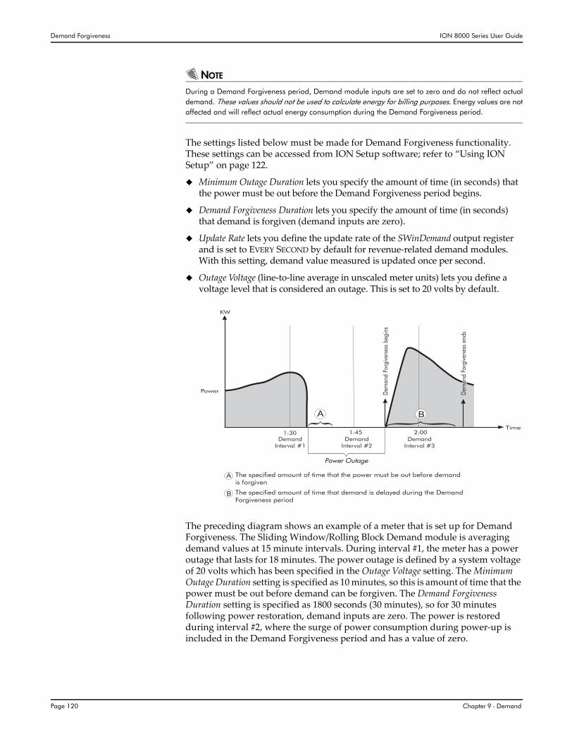
Demand Forgiveness ION 8000 Series User Guide
Page 120 Chapter 9 - Demand
NOTE
During a Demand Forgiveness period, Demand module inputs are set to zero and do not reflect actualdemand. These values should not be used to calculate energy for billing purposes. Energy values are notaffected and will reflect actual energy consumption during the Demand Forgiveness period.
The settings listed below must be made for Demand Forgiveness functionality. These settings can be accessed from ION Setup software; refer to “Using ION Setup” on page 122.
Minimum Outage Duration lets you specify the amount of time (in seconds) that the power must be out before the Demand Forgiveness period begins.
Demand Forgiveness Duration lets you specify the amount of time (in seconds) that demand is forgiven (demand inputs are zero).
Update Rate lets you define the update rate of the SWinDemand output register and is set to EVERY SECOND by default for revenue-related demand modules. With this setting, demand value measured is updated once per second.
Outage Voltage (line-to-line average in unscaled meter units) lets you define a voltage level that is considered an outage. This is set to 20 volts by default.
The preceding diagram shows an example of a meter that is set up for Demand Forgiveness. The Sliding Window/Rolling Block Demand module is averaging demand values at 15 minute intervals. During interval #1, the meter has a power outage that lasts for 18 minutes. The power outage is defined by a system voltage of 20 volts which has been specified in the Outage Voltage setting. The Minimum Outage Duration setting is specified as 10 minutes, so this is amount of time that the power must be out before demand can be forgiven. The Demand Forgiveness Duration setting is specified as 1800 seconds (30 minutes), so for 30 minutes following power restoration, demand inputs are zero. The power is restored during interval #2, where the surge of power consumption during power-up is included in the Demand Forgiveness period and has a value of zero.
The specified amount of time that the power must be out before demandis forgiven
A
B The specified amount of time that demand is delayed during the DemandForgiveness period
1:45
Power Outage
Dem
and
Forg
iven
ess
beg
ins
A
KW
Time
Power Dem
and
Forg
iven
ess
ends
1:30Demand
Interval #1Demand
Interval #2
2:00Demand
Interval #3
B
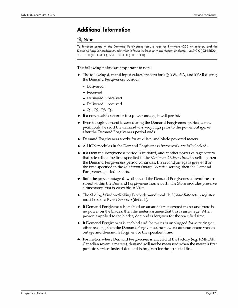
ION 8000 Series User Guide Demand Forgiveness
Chapter 9 - Demand Page 121
Additional Information
NOTE
To function properly, the Demand Forgiveness feature requires firmware v230 or greater, and theDemand Forgiveness framework which is found in these or more recent templates: 1.8.0.0.0 (ION 8500),1.7.0.0.0 (ION 8400), and 1.3.0.0.0 (ION 8300).
The following points are important to note:
The following demand input values are zero for kQ, kW, kVA, and kVAR during the Demand Forgiveness period:
DeliveredReceivedDelivered + receivedDelivered – receivedQ1, Q2, Q3, Q4
If a new peak is set prior to a power outage, it will persist.
Even though demand is zero during the Demand Forgiveness period, a new peak could be set if the demand was very high prior to the power outage, or after the Demand Forgiveness period ends.
Demand Forgiveness works for auxiliary and blade powered meters.
All ION modules in the Demand Forgiveness framework are fully locked.
If a Demand Forgiveness period is initiated, and another power outage occurs that is less than the time specified in the Minimum Outage Duration setting, then the Demand Forgiveness period continues. If a second outage is greater than the time specified in the Minimum Outage Duration setting, then the Demand Forgiveness period restarts.
Both the power outage downtime and the Demand Forgiveness downtime are stored within the Demand Forgiveness framework. The Store modules preserve a timestamp that is viewable in Vista.
The Sliding Window/Rolling Block demand module Update Rate setup register must be set to EVERY SECOND (default).
If Demand Forgiveness is enabled on an auxiliary-powered meter and there is no power on the blades, then the meter assumes that this is an outage. When power is applied to the blades, demand is forgiven for the specified time.
If Demand Forgiveness is enabled and the meter is unplugged for servicing or other reasons, then the Demand Forgiveness framework assumes there was an outage and demand is forgiven for the specified time.
For meters where Demand Forgiveness is enabled at the factory (e.g. RMICAN Canadian revenue meters), demand will not be measured when the meter is first put into service. Instead demand is forgiven for the specified time.
Configuring Demand Forgiveness ION 8000 Series User Guide
Page 122 Chapter 9 - Demand
Configuring Demand ForgivenessDemand Forgiveness is disabled by default. To enable Demand Forgiveness, use ION Setup software to set the:
External Boolean module named “Demand Forgiveness Enable” to ENABLE.
minimum outage duration.
demand forgiveness duration.
outage voltage.
CAUTION
If Demand Forgiveness is enabled, do not use demand values to calculate energy for billing purposes.
Using the Front PanelYou cannot enable or edit Demand Forgiveness settings via the front panel.
Using ION SetupION Setup version 1.1 and later supports the Demand Forgiveness feature:
1. Launch ION Setup and double-click the Setup Assistant.
2. Select the Demand setup screen, and click on the Demand Forgiveness tab.
3. Select Demand Forgiveness Enable.
Click Edit, (provide a password if requested), and select ON.
4. Select Min Outage Duration, and click Edit.
Type the amount of time (in seconds) that the power must be out before the Demand Forgiveness period starts, and click OK.
5. Select Demand Forgiveness Duration and click Edit.
Type the amount of time (in seconds) that demand is forgiven (demand inputs are zero), and click OK.
6. If required, select Outage Voltage and click Edit.
Type the minimum voltage (line-to-line average in unscaled meter units) that is considered an outage; this is set to 20 volts by default but you can adjust this.
Page 123
10 Inputs / OutputsThis chapter provides information on the meter’s various digital and analog inputs and outputs (I/O).
Refer to your Installation Guide for instructions on wiring inputs and outputs and for the general meter I/O specifications.
In this chapter
Introduction . . . . . . . . . . . . . . . . . . . . . . . . . . . . . . . . . . . . . . . . . . . . . . 124Specifying an I/O Port in an ION Module . . . . . . . . . . . . . . . . . . . . . . . . . . . . . . . 126Using the Onboard Digital Outputs . . . . . . . . . . . . . . . . . . . . . . . . . . . . . . . . . . . . 128
Output Modules .................................................................................................. 129Using the Onboard Digital Inputs . . . . . . . . . . . . . . . . . . . . . . . . . . . . . . . . . . . . . . 130Analog Outputs . . . . . . . . . . . . . . . . . . . . . . . . . . . . . . . . . . . . . . . . . . . . . . . . . . . . . 131Setting the Zero and Full Scales . . . . . . . . . . . . . . . . . . . . . . . . . . . . . . . . . . . . . . . . 131
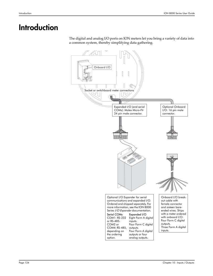
Introduction ION 8000 Series User Guide
Page 124 Chapter 10 - Inputs / Outputs
IntroductionThe digital and analog I/O ports on ION meters let you bring a variety of data into a common system, thereby simplifying data gathering.
Onboard I/O
Expanded I/O (and serial COMs): Molex Micro-Fit 24 pin male connector.
Optional Onboard I/O: 16 pin male connector.
Socket or switchboard meter connections
Onboard I/O break-out cable with female connector and sixteen bare-ended wires. Ships with a meter ordered with onboard I/O: Four Form C digital outputs. Three Form A digital inputs.
Optional I/O Expander for serial communications and expanded I/O. Ordered and shipped separately. For more information, see the ION 8000 Series I/O Expander documentation. Serial COMs COM1: RS-232 or RS-485.COM2 or COM4: RS-485, depending on the ordering option.
Expanded I/OEight Form A digital inputs.Four Form C digital outputs. Four Form A digital outputs or four analog outputs.
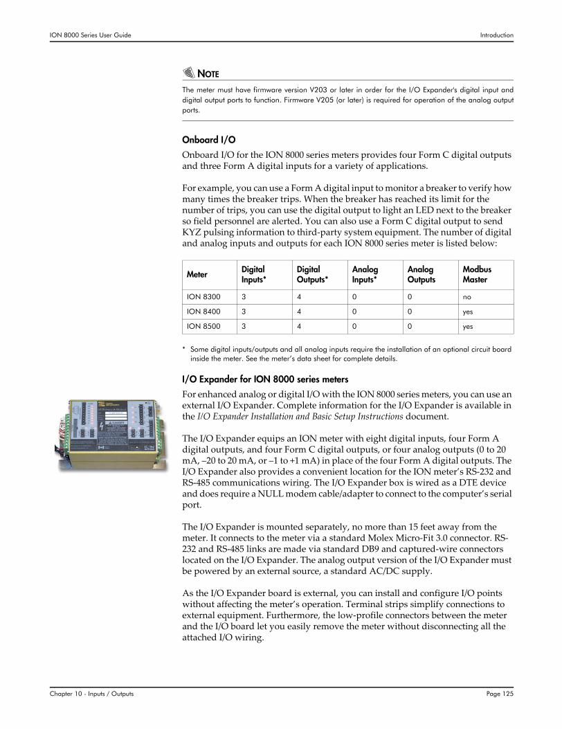
ION 8000 Series User Guide Introduction
Chapter 10 - Inputs / Outputs Page 125
NOTE
The meter must have firmware version V203 or later in order for the I/O Expander's digital input anddigital output ports to function. Firmware V205 (or later) is required for operation of the analog outputports.
Onboard I/O
Onboard I/O for the ION 8000 series meters provides four Form C digital outputs and three Form A digital inputs for a variety of applications.
For example, you can use a Form A digital input to monitor a breaker to verify how many times the breaker trips. When the breaker has reached its limit for the number of trips, you can use the digital output to light an LED next to the breaker so field personnel are alerted. You can also use a Form C digital output to send KYZ pulsing information to third-party system equipment. The number of digital and analog inputs and outputs for each ION 8000 series meter is listed below:
* Some digital inputs/outputs and all analog inputs require the installation of an optional circuit board inside the meter. See the meter’s data sheet for complete details.
I/O Expander for ION 8000 series meters
For enhanced analog or digital I/O with the ION 8000 series meters, you can use an external I/O Expander. Complete information for the I/O Expander is available in the I/O Expander Installation and Basic Setup Instructions document.
The I/O Expander equips an ION meter with eight digital inputs, four Form A digital outputs, and four Form C digital outputs, or four analog outputs (0 to 20 mA, –20 to 20 mA, or –1 to +1 mA) in place of the four Form A digital outputs. The I/O Expander also provides a convenient location for the ION meter’s RS-232 and RS-485 communications wiring. The I/O Expander box is wired as a DTE device and does require a NULL modem cable/adapter to connect to the computer’s serial port.
The I/O Expander is mounted separately, no more than 15 feet away from the meter. It connects to the meter via a standard Molex Micro-Fit 3.0 connector. RS-232 and RS-485 links are made via standard DB9 and captured-wire connectors located on the I/O Expander. The analog output version of the I/O Expander must be powered by an external source, a standard AC/DC supply.
As the I/O Expander board is external, you can install and configure I/O points without affecting the meter’s operation. Terminal strips simplify connections to external equipment. Furthermore, the low-profile connectors between the meter and the I/O board let you easily remove the meter without disconnecting all the attached I/O wiring.
Meter Digital Inputs*
Digital Outputs*
Analog Inputs*
Analog Outputs
Modbus Master
ION 8300 3 4 0 0 no
ION 8400 3 4 0 0 yes
ION 8500 3 4 0 0 yes
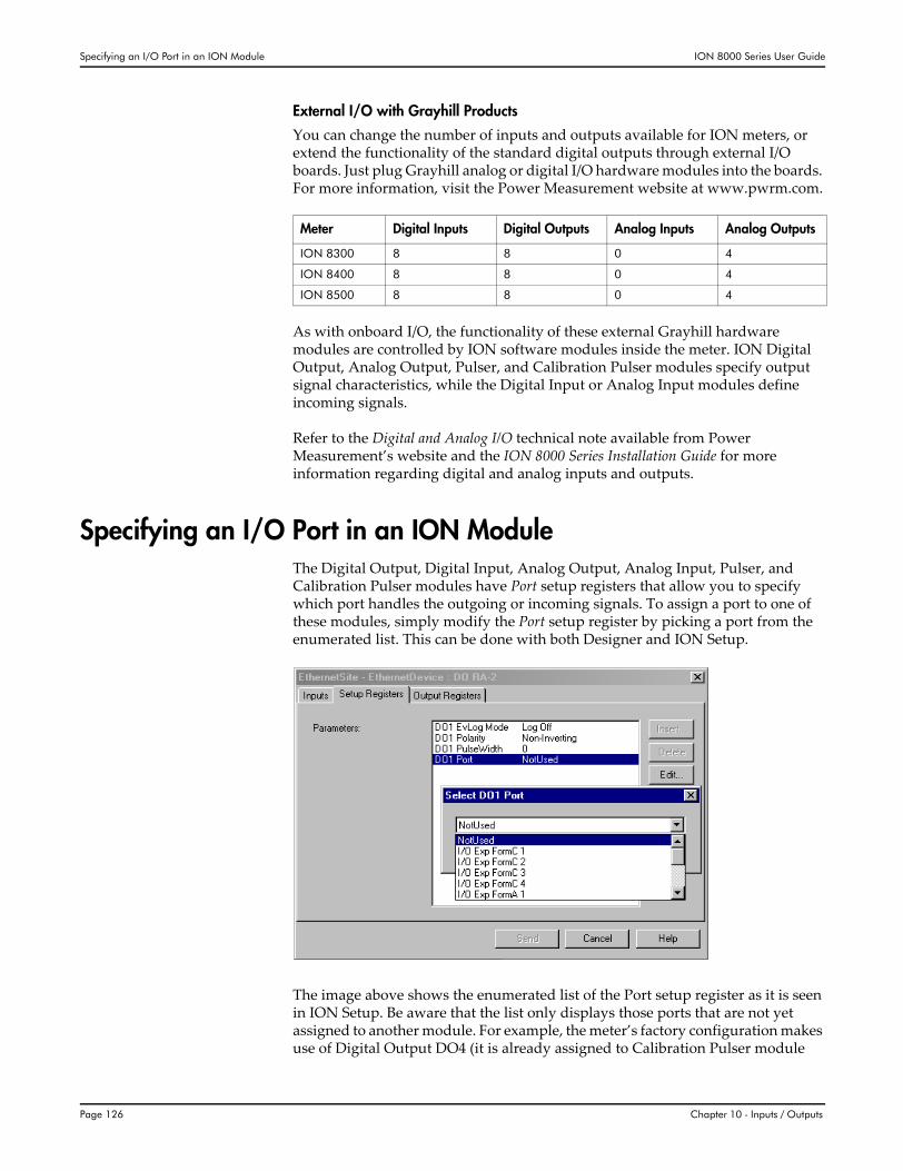
Specifying an I/O Port in an ION Module ION 8000 Series User Guide
Page 126 Chapter 10 - Inputs / Outputs
External I/O with Grayhill Products
You can change the number of inputs and outputs available for ION meters, or extend the functionality of the standard digital outputs through external I/O boards. Just plug Grayhill analog or digital I/O hardware modules into the boards. For more information, visit the Power Measurement website at www.pwrm.com.
As with onboard I/O, the functionality of these external Grayhill hardware modules are controlled by ION software modules inside the meter. ION Digital Output, Analog Output, Pulser, and Calibration Pulser modules specify output signal characteristics, while the Digital Input or Analog Input modules define incoming signals.
Refer to the Digital and Analog I/O technical note available from Power Measurement’s website and the ION 8000 Series Installation Guide for more information regarding digital and analog inputs and outputs.
Specifying an I/O Port in an ION ModuleThe Digital Output, Digital Input, Analog Output, Analog Input, Pulser, and Calibration Pulser modules have Port setup registers that allow you to specify which port handles the outgoing or incoming signals. To assign a port to one of these modules, simply modify the Port setup register by picking a port from the enumerated list. This can be done with both Designer and ION Setup.
The image above shows the enumerated list of the Port setup register as it is seen in ION Setup. Be aware that the list only displays those ports that are not yet assigned to another module. For example, the meter’s factory configuration makes use of Digital Output DO4 (it is already assigned to Calibration Pulser module
Meter Digital Inputs Digital Outputs Analog Inputs Analog Outputs
ION 8300 8 8 0 4
ION 8400 8 8 0 4
ION 8500 8 8 0 4
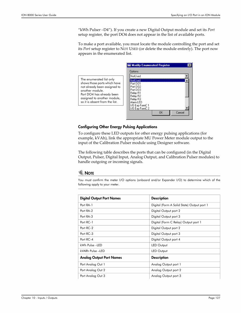
ION 8000 Series User Guide Specifying an I/O Port in an ION Module
Chapter 10 - Inputs / Outputs Page 127
“kWh Pulser –D4”). If you create a new Digital Output module and set its Port setup register, the port DO4 does not appear in the list of available ports.
To make a port available, you must locate the module controlling the port and set its Port setup register to NOT USED (or delete the module entirely). The port now appears in the enumerated list.
Configuring Other Energy Pulsing Applications
To configure these LED outputs for other energy pulsing applications (for example, kVAh), link the appropriate MU Power Meter module output to the input of the Calibration Pulser module using Designer software.
The following table describes the ports that can be configured (in the Digital Output, Pulser, Digital Input, Analog Output, and Calibration Pulser modules) to handle outgoing or incoming signals.
NOTE
You must confirm the meter I/O options (onboard and/or Expander I/O) to determine which of thefollowing apply to your meter.
Digital Output Port Names Description
Port RA-1 Digital (Form A Solid State) Output port 1
Port RA-2 Digital Output port 2
Port RA-3 Digital Output port 3
Port RC-1 Digital (Form C Relay) Output port 1
Port RC-2 Digital Output port 2
Port RC-3 Digital Output port 3
Port RC-4 Digital Output port 4
kWh Pulse –LED LED Output
kVARh Pulse –LED LED Output
Analog Output Port Names Description
Port Analog Out 1 Analog Output port 1
Port Analog Out 2 Analog Output port 2
Port Analog Out 3 Analog Output port 3
The enumerated list only shows those ports which have not already been assigned to another module.Port DO4 has already been assigned to another module, so it is absent from the list.
Using the Onboard Digital Outputs ION 8000 Series User Guide
Page 128 Chapter 10 - Inputs / Outputs
Using the Onboard Digital OutputsDigital outputs are used for hardware relay control or pulse counting applications. For example, an ION meter’s digital outputs can provide on/off control signals for capacitor banks, generators, and other equipment. The digital output ports can also send out status signals or kWh pulses, if the receiving device determines energy usage by counting pulses.
Onboard I/O for the ION 8000 Series meters provides four Form C digital outputs and three Form A digital inputs. You can use a Form A digital input to monitor a breaker to verify how many times the breaker trips. When the breaker has reached its limit for the number of trips, you can use the digital output to light an LED next to the breaker so field personnel are alerted. You can also use a Form C digital output to send KYZ pulsing information to third-party system equipment.
All digital outputs can deliver a continuous signal or a pulse. (Contact Power Measurement for complete information regarding relay applications.)
CAUTION
The relay outputs of the meter should never be used for primary protection functions. Be sure that you arefamiliar with warnings at start of this document, as well as those presented your meter’s Installation & Basic Setup Instructions.
These outputs can be controlled by Digital Output modules, Pulser modules, or Calibration Pulser modules, depending on the application. For relay and control, the Digital Output module is used. For pulsing applications, the Pulser and Calibration Pulser modules are generally used. All of these modules can act as intermediaries between the hardware port and the other modules in the meter. They define the characteristics of outgoing signals.
Port Analog Out 4 Analog Output port 4
Digital Input Port Names Description
Port DI-S1 Digital (Status) Input port 1 (I/O Expander)
Port DI-S2 Digital Input port 2 (I/O Expander)
Port DI-S3 Digital Input port 3 (I/O Expander)
Port DI-S4 Digital Input port 4 (I/O Expander)
Port DI-S5 Digital Input port 5 (I/O Expander)
Port DI-S6 Digital Input port 6 (I/O Expander)
Port DI-S7 Digital Input port 7 (I/O Expander)
Port DI-S8 Digital Input port 8 (I/O Expander)
Port DI-S9 Digital Input port 9 (Onboard I/O)
Port DI-S10 Digital Input port 10 (Onboard I/O)
Port DI-S11 Digital Input port 11 (Onboard I/O)
ION 8000 Series User Guide Using the Onboard Digital Outputs
Chapter 10 - Inputs / Outputs Page 129
Output ModulesBoth the Form A and Form C relays can be controlled with Digital Output modules, Pulser modules, or Calibration Pulser modules. By default, six Digital Output modules (labeled DO RA-2 to DO RA-4 and DO RC-1 to DO RC-4) are already created for this purpose. You can either use these modules, or create and configure other modules to control the output ports.
Calibration Pulser modules allow you to generate high accuracy energy pulses for calibration testing purposes. They integrate instantaneous power inputs.
Digital Output modules accept Boolean inputs, and output a continuous signal or pulses.
Pulser modules convert instantaneous pulses to pulses or transitions.
Consult the online ION Reference if you require more information about these ION modules.
Configure the settings of the controlling module to match your requirements. The settings in these modules are as follows:
1 See “Calibration Pulsing Relay DO4,” below.
ION Module Setup Registers Available Settings Creation Default Description
Digital Output
Port
Not UsedI/O Exp FormC 1I/O Exp FormC 2I/O Exp FormC 3I/O Exp FormC 4I/O Exp FormA 1I/O Exp FormA 2I/O Exp FormA 3I/O Exp FormA 4On-Board Form C 1On-Board Form C 2On-Board Form C 3On-Board Form C 4
Not Used The output hardware channel
Pulse Width 0 to 2000000 0 Pulse Width, in seconds(0 for continuous pulse)
Polarity Inverting or Non-Inverting Non-Inverting Inverted or non-inverted output
EvLog Mode Log on or Log off Log off Whether or not to log status changes in the Event Log
Pulser
Port As per Digital Output, above Not Used The output hardware channel
PulseWidth 0.020 to 2000000 1 Pulse width, in seconds
OutputMode Pulse or KYZ Pulse Full pulse or KYZ (transition pulse)
Polarity Inverting or Non-Inverting Non-Inverting Inverted or non-inverted output
Calibration Pulser1
Port As per Digital Output, above Not Used The output hardware channel
Pulse Width 0.010 to 1.000 0.05 Pulse Width, in seconds
Kt 0.01 to 1000000000 1.8 Watts per pulse
Int Mode Forward, Reverse, Absolute, or Net Absolute Integration modes that may be selected
OutputMode Pulse or KYZ Pulse Full pulse or KYZ (transition pulse)
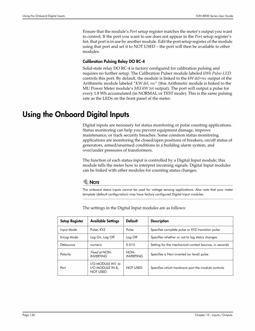
Using the Onboard Digital Inputs ION 8000 Series User Guide
Page 130 Chapter 10 - Inputs / Outputs
Ensure that the module’s Port setup register matches the meter’s output you want to control. If the port you want to use does not appear in the Port setup register’s list, that port is in use by another module. Edit the port setup register of the module using that port and set it to NOT USED – the port will then be available to other modules.
Calibration Pulsing Relay DO RC-4
Solid-state relay DO RC-4 is factory configured for calibration pulsing and requires no further setup. The Calibration Pulser module labeled kWh Pulse-LED controls this port. By default, the module is linked to the kW del+rec output of the Arithmetic module labeled “KW del, rec” (this Arithmetic module is linked to the MU Power Meter module’s MU kW tot output). The port will output a pulse for every 1.8 Wh accumulated (in NORMAL or TEST mode). This is the same pulsing rate as the LEDs on the front panel of the meter.
Using the Onboard Digital InputsDigital inputs are necessary for status monitoring or pulse counting applications. Status monitoring can help you prevent equipment damage, improve maintenance, or track security breaches. Some common status monitoring applications are monitoring the closed/open positions of breakers, on/off status of generators, armed/unarmed conditions in a building alarm system, and over/under pressures of transformers.
The function of each status input is controlled by a Digital Input module; this module tells the meter how to interpret incoming signals. Digital Input modules can be linked with other modules for counting status changes.
NOTE
The onboard status inputs cannot be used for voltage sensing applications. Also note that your metertemplate (default configuration) may have factory configured Digital Input modules.
The settings in the Digital Input modules are as follows:
Setup Register Available Settings Default Description
Input Mode Pulse, KYZ Pulse Specifies complete pulse or KYZ transition pulse
EvLog Mode Log On, Log Off Log Off Specifies whether or not to log status changes
Debounce numeric 0.015 Setting for the mechanical contact bounce, in seconds
Polarity Fixed at NON-INVERTING
NON-INVERTING Specifies a Non-inverted (or level) pulse
PortI/O MODULE IN1 to I/O MODULE IN 8, NOT USED
NOT USED Specifies which hardware port the module controls
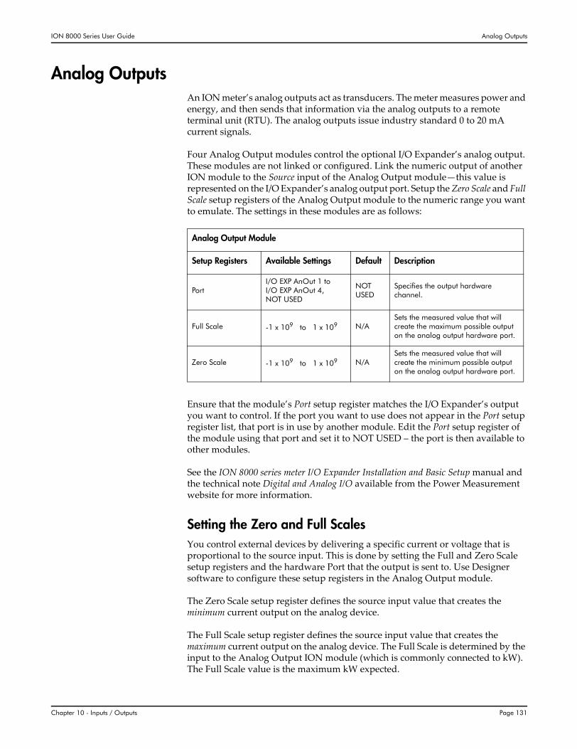
ION 8000 Series User Guide Analog Outputs
Chapter 10 - Inputs / Outputs Page 131
Analog OutputsAn ION meter’s analog outputs act as transducers. The meter measures power and energy, and then sends that information via the analog outputs to a remote terminal unit (RTU). The analog outputs issue industry standard 0 to 20 mA current signals.
Four Analog Output modules control the optional I/O Expander’s analog output. These modules are not linked or configured. Link the numeric output of another ION module to the Source input of the Analog Output module—this value is represented on the I/O Expander’s analog output port. Setup the Zero Scale and Full Scale setup registers of the Analog Output module to the numeric range you want to emulate. The settings in these modules are as follows:
Ensure that the module’s Port setup register matches the I/O Expander’s output you want to control. If the port you want to use does not appear in the Port setup register list, that port is in use by another module. Edit the Port setup register of the module using that port and set it to NOT USED – the port is then available to other modules.
See the ION 8000 series meter I/O Expander Installation and Basic Setup manual and the technical note Digital and Analog I/O available from the Power Measurement website for more information.
Setting the Zero and Full ScalesYou control external devices by delivering a specific current or voltage that is proportional to the source input. This is done by setting the Full and Zero Scale setup registers and the hardware Port that the output is sent to. Use Designer software to configure these setup registers in the Analog Output module.
The Zero Scale setup register defines the source input value that creates the minimum current output on the analog device.
The Full Scale setup register defines the source input value that creates the maximum current output on the analog device. The Full Scale is determined by the input to the Analog Output ION module (which is commonly connected to kW). The Full Scale value is the maximum kW expected.
Analog Output Module
Setup Registers Available Settings Default Description
PortI/O EXP AnOut 1 toI/O EXP AnOut 4,NOT USED
NOT USED
Specifies the output hardware channel.
Full Scale -1 x 10⁹ to 1 x 10⁹ N/ASets the measured value that will create the maximum possible output on the analog output hardware port.
Zero Scale -1 x 10⁹ to 1 x 10⁹ N/ASets the measured value that will create the minimum possible output on the analog output hardware port.
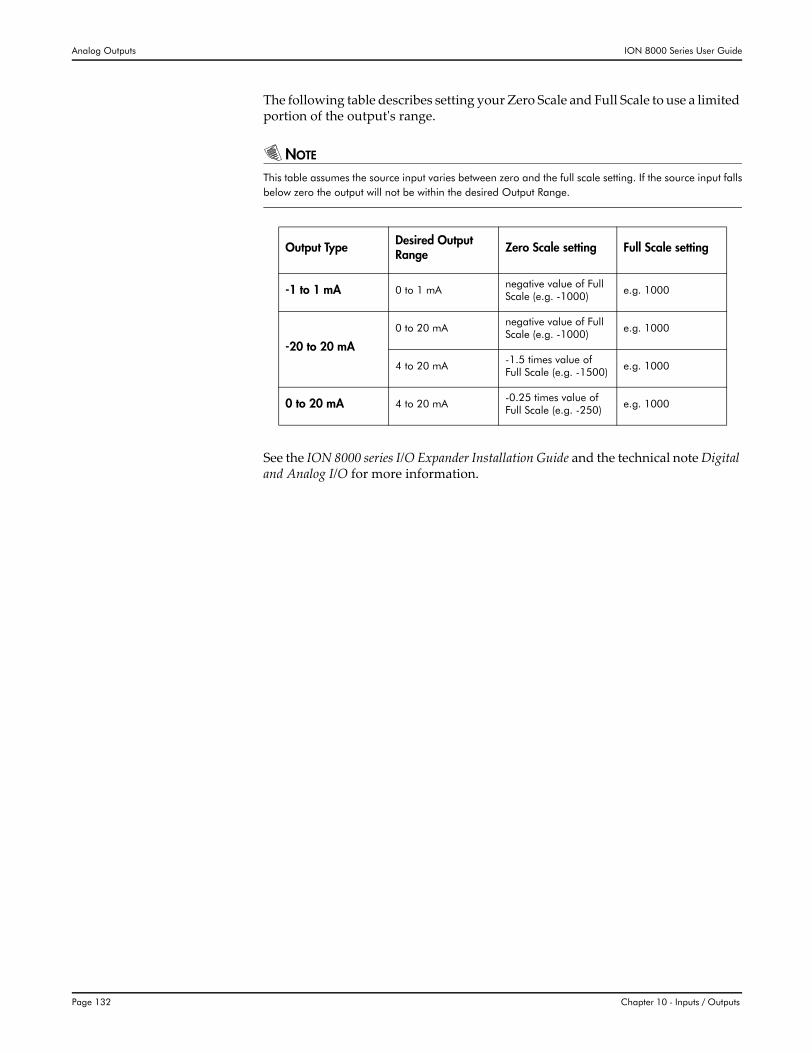
Analog Outputs ION 8000 Series User Guide
Page 132 Chapter 10 - Inputs / Outputs
The following table describes setting your Zero Scale and Full Scale to use a limited portion of the output's range.
NOTE
This table assumes the source input varies between zero and the full scale setting. If the source input fallsbelow zero the output will not be within the desired Output Range.
See the ION 8000 series I/O Expander Installation Guide and the technical note Digital and Analog I/O for more information.
Output Type Desired Output Range Zero Scale setting Full Scale setting
-1 to 1 mA 0 to 1 mA negative value of Full Scale (e.g. -1000) e.g. 1000
-20 to 20 mA
0 to 20 mA negative value of Full Scale (e.g. -1000) e.g. 1000
4 to 20 mA -1.5 times value of Full Scale (e.g. -1500) e.g. 1000
0 to 20 mA 4 to 20 mA -0.25 times value of Full Scale (e.g. -250) e.g. 1000
Page 133
11 Energy PulsingThis chapter provides instructions for configuring energy pulsing on your meter.
In this chapter
Introduction . . . . . . . . . . . . . . . . . . . . . . . . . . . . . . . . . . . . . . . . . . . . . . 134
Configuring Energy Pulsing . . . . . . . . . . . . . . . . . . . . . . . . . . . . . . . . . . . 134Using the Front Panel ......................................................................................... 134Using ION Setup ................................................................................................. 134Using Designer .................................................................................................... 135
Pulser Module Settings . . . . . . . . . . . . . . . . . . . . . . . . . . . . . . . . . . . . . . . . . . . . . . . 135Calibration Pulser Module Settings . . . . . . . . . . . . . . . . . . . . . . . . . . . . . . . . . . . . 136Energy Pulsing with LEDs . . . . . . . . . . . . . . . . . . . . . . . . . . . . . . . . . . . . . . . . . . . . 137
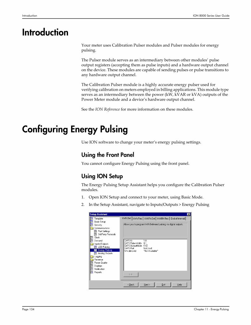
Introduction ION 8000 Series User Guide
Page 134 Chapter 11 - Energy Pulsing
IntroductionYour meter uses Calibration Pulser modules and Pulser modules for energy pulsing.
The Pulser module serves as an intermediary between other modules’ pulse output registers (accepting them as pulse inputs) and a hardware output channel on the device. These modules are capable of sending pulses or pulse transitions to any hardware output channel.
The Calibration Pulser module is a highly accurate energy pulser used for verifying calibration on meters employed in billing applications. This module type serves as an intermediary between the power (kW, kVAR or kVA) outputs of the Power Meter module and a device’s hardware output channel.
See the ION Reference for more information on these modules.
Configuring Energy PulsingUse ION software to change your meter’s energy pulsing settings.
Using the Front PanelYou cannot configure Energy Pulsing using the front panel.
Using ION SetupThe Energy Pulsing Setup Assistant helps you configure the Calibration Pulser modules.
1. Open ION Setup and connect to your meter, using Basic Mode.
2. In the Setup Assistant, navigate to Inputs/Outputs > Energy Pulsing
ION 8000 Series User Guide Pulser Module Settings
Chapter 11 - Energy Pulsing Page 135
3. Click any of the first four tabs; each tab corresponds to a Calibration Pulser module. Configure each module as necessary.
4. Click the End of Interval tab to configure the end of energy pulsing.
You can configure both the Calibration Pulser and Pulser modules using Advanced Mode.
1. Connect to your meter, using Advanced Mode.
2. Click the module you wish to configure.
Using DesignerOpen your meter in Designer and navigate to the Energy Pulsing Setup Framework. Right-click a module to edit.
Pulser Module SettingsThe Pulser module contains the following setup registers:
Five common parameters (kWh del, kWh rec, kVARh del, kVARh rec, and kW sd del) are already linked to the Pulser modules for you.
NOTE
For safety reasons, no hardware channel is pre-selected. To make use of these links, you must configurethe Pulser modules’ Port setup registers to the appropriate hardware port that receives the output.
Setup Register Function Default
Pulse Width This register specifies the width of the output pulses (in seconds).
1
OutputMode This register defines whether the output is a complete pulse or a transition pulse (KYZ). Pulse
Polarity This register specifies the polarity of a pulse output. It has no effect if OutputMode is KYZ. Non-inverting
PortThis register specifies which hardware port the output appears on. Only those hardware channels that are still available appear in this list.
Not Used
Calibration Pulser Module Settings ION 8000 Series User Guide
Page 136 Chapter 11 - Energy Pulsing
Calibration Pulser Module SettingsConfigure the solid-state output D4 for calibration pulsing by editing the setup registers of the module labeled “kWh Pulser –D4”. By default, the output on a standard meter generates a pulse for every 1.8 Wh accumulated. This is the same pulsing rate as the middle front panel LED (controlled by a Calibration Pulser module labeled “kWh Pulser –LED”). Modify the pulsing rate of either channel by changing the value of the Kt setup register of the Calibration Pulser module controlling them (see below).
The following setup registers are available in the Calibration Pulser module:
Setup Register Function Default
Pulse Width This register specifies the width of the pulses sent to the hardware channel (in seconds). The Calibration Pulser module maintains a minimum duty cycle of 50% on the output pulse train. 0.05
KtThe numeric bounded register defines how much energy the module accumulates before a pulse is sent to the hardware channel. An industry standard for energy pulsing is 1.8, or one pulse per 1.8 energy-hours.
1.80
Int Mode Specifies the modes of integration that may be selected. Absolute
OutputMode This register specifies whether the output is a complete pulse (Pulse) or a change of state transition (KYZ).
Pulse
Port This register specifies which hardware port the pulse/KYZ transition appears on. Only those hardware channels that are still available appear in this list. Not Used
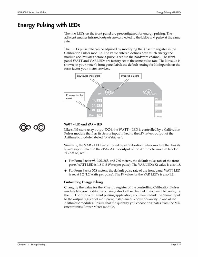
ION 8000 Series User Guide Energy Pulsing with LEDs
Chapter 11 - Energy Pulsing Page 137
Energy Pulsing with LEDsThe two LEDs on the front panel are preconfigured for energy pulsing. The adjacent smaller infrared outputs are connected to the LEDs and pulse at the same rate.
The LED's pulse rate can be adjusted by modifying the Kt setup register in the Calibration Pulser module. The value entered defines how much energy the module accumulates before a pulse is sent to the hardware channel. The front panel WATT and VAR LEDs are factory set to the same pulse rate. The Kt value is shown on your meter’s front panel label; the default setting for Kt depends on the form factor your meter services.
WATT – LED and VAR – LED
Like solid-state relay output DO4, the WATT – LED is controlled by a Calibration Pulser module that has its Source input linked to the kW del+rec output of the Arithmetic module labeled “KW del, rec”.
Similarly, the VAR – LED is controlled by a Calibration Pulser module that has its Source input linked to the kVAR del+rec output of the Arithmetic module labeled “kVAR del, rec”.
For Form Factor 9S, 39S, 36S, and 76S meters, the default pulse rate of the front panel WATT LED is 1.8 (1.8 Watts per pulse). The VAR LED's Kt value is also 1.8.
For Form Factor 35S meters, the default pulse rate of the front panel WATT LED is set at 1.2 (1.2 Watts per pulse). The Kt value for the VAR LED's is also 1.2.
Customizing Energy Pulsing
Changing the value for the Kt setup register of the controlling Calibration Pulser module lets you modify the pulsing rate of either channel. If you want to configure the LED port for a different pulsing application, you must re-link the Source input to the output register of a different instantaneous power quantity in one of the Arithmetic modules. Ensure that the quantity you choose originates from the MU (meter units) Power Meter module.
LED pulse indicators Infrared pulsers
Kt value for the meter

Page 139
12 LoggingThe ION 8000 series meter has powerful data logging and event recording capabilities. Data and event logs recorded by the meter are prioritized and stored onboard. Data is retrieved periodically by the ION Enterprise software Log Server (or other third party application).
If you use ION Enterprise software, all retrieved data from your system is stored in an ODBC-compliant database. The information in the database can be viewed and analyzed using ION Enterprise software applications such as Vista (for viewing), or Reporter (for organizing and presenting data).
In this chapter
Data Logging . . . . . . . . . . . . . . . . . . . . . . . . . . . . . . . . . . . . . . . . . . . . . 140Configuring Data Logging . . . . . . . . . . . . . . . . . . . . . . . . . . . . . . . . . . . . . . . . . . . . 140
Using the Front Panel ......................................................................................... 140Using ION Setup ................................................................................................. 140Changing the Parameters that are Logged ...................................................... 142Changing Waveform Recording ....................................................................... 142Default Logging Capacity .................................................................................. 142Changing the Log Depths .................................................................................. 142Changing the Frequency of Logging ................................................................ 143Default Logging Configuration ......................................................................... 143
Data Logging ION 8000 Series User Guide
Page 140 Chapter 12 - Logging
Data LoggingThe meter ships with a comprehensive data-logging configuration. Information regarding the default logging capacity and default logging configuration can be found in “Default Logging Capacity” on page 142.
To learn more about the data recorder modules in your meter, refer to ION Device Templates at www.pwrm.com. This file lists all of the ION modules available in the current version of your meter, and the total number of each module. It also shows the ranges or options available for each module’s setup registers.
Configuring Data LoggingUse ION software to change your meter’s logging settings.
Using the Front PanelYou cannot configure Logging using the front panel.
Using ION SetupThe Logging Setup Assistant helps you configure meter data logging.
1. Open ION Setup and connect to your meter, using Basic Mode.
2. In the Setup Assistant, navigate to the Logging folder.
Use the two screens (Memory, Load Profile) to configure your logging settings.
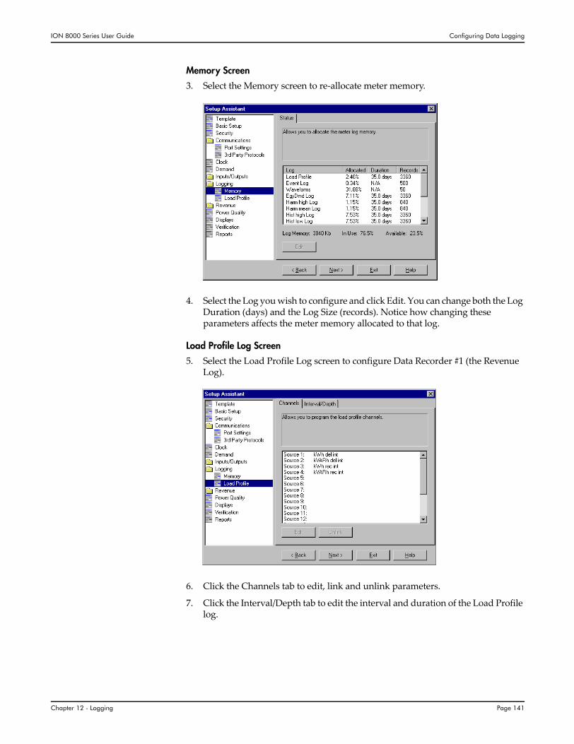
ION 8000 Series User Guide Configuring Data Logging
Chapter 12 - Logging Page 141
Memory Screen
3. Select the Memory screen to re-allocate meter memory.
4. Select the Log you wish to configure and click Edit. You can change both the Log Duration (days) and the Log Size (records). Notice how changing these parameters affects the meter memory allocated to that log.
Load Profile Log Screen
5. Select the Load Profile Log screen to configure Data Recorder #1 (the Revenue Log).
6. Click the Channels tab to edit, link and unlink parameters.
7. Click the Interval/Depth tab to edit the interval and duration of the Load Profile log.
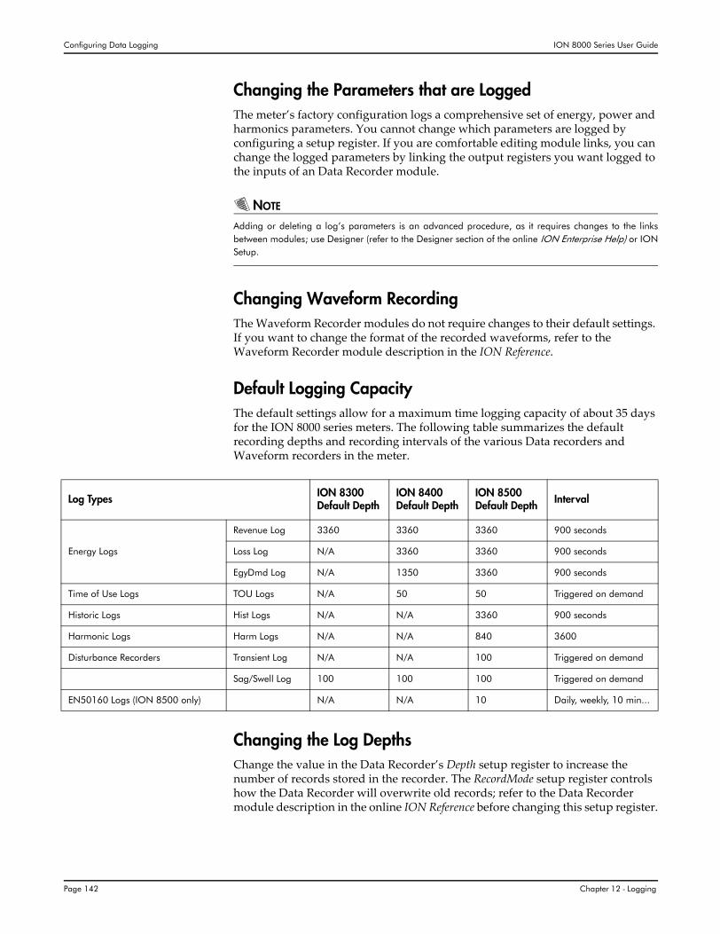
Configuring Data Logging ION 8000 Series User Guide
Page 142 Chapter 12 - Logging
Changing the Parameters that are LoggedThe meter’s factory configuration logs a comprehensive set of energy, power and harmonics parameters. You cannot change which parameters are logged by configuring a setup register. If you are comfortable editing module links, you can change the logged parameters by linking the output registers you want logged to the inputs of an Data Recorder module.
NOTE
Adding or deleting a log’s parameters is an advanced procedure, as it requires changes to the linksbetween modules; use Designer (refer to the Designer section of the online ION Enterprise Help) or IONSetup.
Changing Waveform RecordingThe Waveform Recorder modules do not require changes to their default settings. If you want to change the format of the recorded waveforms, refer to the Waveform Recorder module description in the ION Reference.
Default Logging CapacityThe default settings allow for a maximum time logging capacity of about 35 days for the ION 8000 series meters. The following table summarizes the default recording depths and recording intervals of the various Data recorders and Waveform recorders in the meter.
Changing the Log DepthsChange the value in the Data Recorder’s Depth setup register to increase the number of records stored in the recorder. The RecordMode setup register controls how the Data Recorder will overwrite old records; refer to the Data Recorder module description in the online ION Reference before changing this setup register.
Log Types ION 8300 Default Depth
ION 8400 Default Depth
ION 8500 Default Depth Interval
Energy Logs
Revenue Log 3360 3360 3360 900 seconds
Loss Log N/A 3360 3360 900 seconds
EgyDmd Log N/A 1350 3360 900 seconds
Time of Use Logs TOU Logs N/A 50 50 Triggered on demand
Historic Logs Hist Logs N/A N/A 3360 900 seconds
Harmonic Logs Harm Logs N/A N/A 840 3600
Disturbance Recorders Transient Log N/A N/A 100 Triggered on demand
Sag/Swell Log 100 100 100 Triggered on demand
EN50160 Logs (ION 8500 only) N/A N/A 10 Daily, weekly, 10 min...
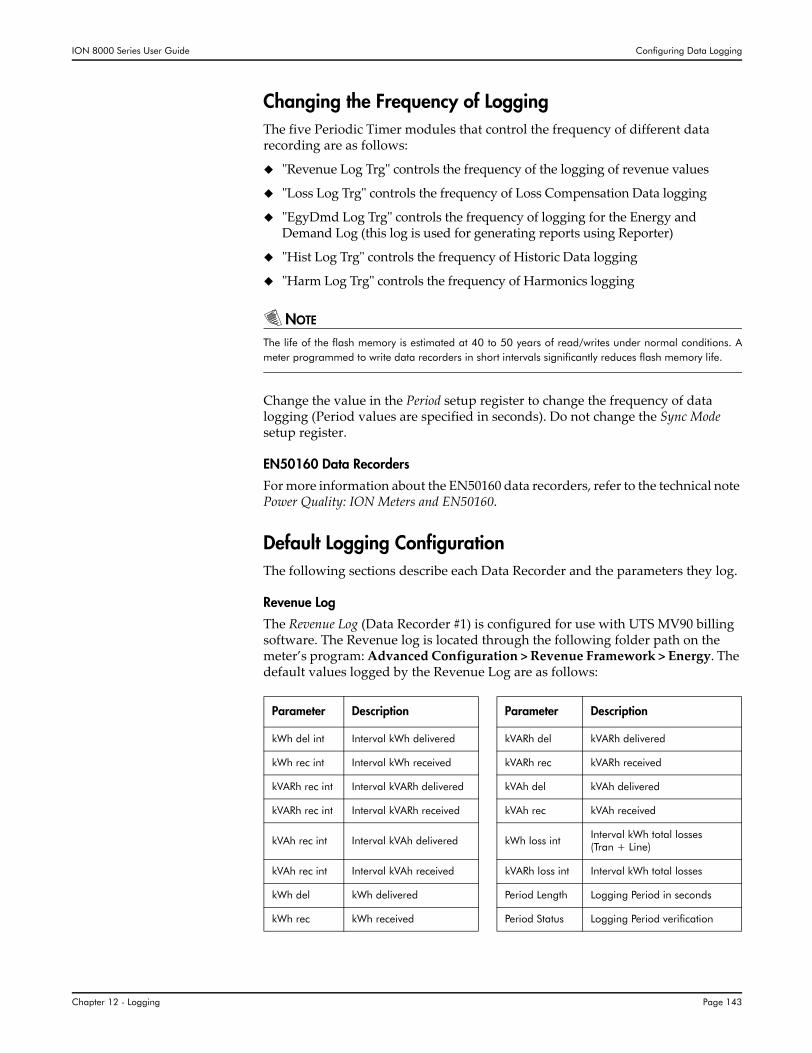
ION 8000 Series User Guide Configuring Data Logging
Chapter 12 - Logging Page 143
Changing the Frequency of LoggingThe five Periodic Timer modules that control the frequency of different data recording are as follows:
"Revenue Log Trg" controls the frequency of the logging of revenue values
"Loss Log Trg" controls the frequency of Loss Compensation Data logging
"EgyDmd Log Trg" controls the frequency of logging for the Energy and Demand Log (this log is used for generating reports using Reporter)
"Hist Log Trg" controls the frequency of Historic Data logging
"Harm Log Trg" controls the frequency of Harmonics logging
NOTE
The life of the flash memory is estimated at 40 to 50 years of read/writes under normal conditions. Ameter programmed to write data recorders in short intervals significantly reduces flash memory life.
Change the value in the Period setup register to change the frequency of data logging (Period values are specified in seconds). Do not change the Sync Mode setup register.
EN50160 Data Recorders
For more information about the EN50160 data recorders, refer to the technical note Power Quality: ION Meters and EN50160.
Default Logging ConfigurationThe following sections describe each Data Recorder and the parameters they log.
Revenue Log
The Revenue Log (Data Recorder #1) is configured for use with UTS MV90 billing software. The Revenue log is located through the following folder path on the meter’s program: Advanced Configuration > Revenue Framework > Energy. The default values logged by the Revenue Log are as follows:
Parameter Description Parameter Description
kWh del int Interval kWh delivered kVARh del kVARh delivered
kWh rec int Interval kWh received kVARh rec kVARh received
kVARh rec int Interval kVARh delivered kVAh del kVAh delivered
kVARh rec int Interval kVARh received kVAh rec kVAh received
kVAh rec int Interval kVAh delivered kWh loss int Interval kWh total losses(Tran + Line)
kVAh rec int Interval kVAh received kVARh loss int Interval kWh total losses
kWh del kWh delivered Period Length Logging Period in seconds
kWh rec kWh received Period Status Logging Period verification
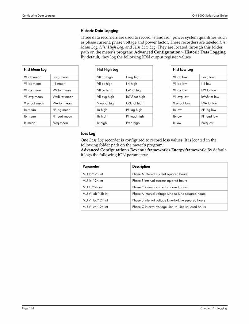
Configuring Data Logging ION 8000 Series User Guide
Page 144 Chapter 12 - Logging
Historic Data Logging
Three data recorders are used to record “standard” power system quantities, such as phase current, phase voltage and power factor. These recorders are labeled Hist Mean Log, Hist High Log, and Hist Low Log. They are located through this folder path on the meter’s program: Advanced Configuration > Historic Data Logging. By default, they log the following ION output register values:
Loss Log
One Loss Log recorder is configured to record loss values. It is located in the following folder path on the meter’s program: Advanced Configuration > Revenue framework > Energy framework. By default, it logs the following ION parameters:
Hist Mean Log Hist High Log Hist Low Log
Vll ab mean I avg mean Vll ab high I avg high Vll ab low I avg low
Vll bc mean I 4 mean Vll bc high I 4 high Vll bc low I 4 low
Vll ca mean kW tot mean Vll ca high kW tot high Vll ca low kW tot low
Vll avg mean kVAR tot mean Vll avg high kVAR tot high Vll avg low kVAR tot low
V unbal mean kVA tot mean V unbal high kVA tot high V unbal low kVA tot low
Ia mean PF lag mean Ia high PF lag high Ia low PF lag low
Ib mean PF lead mean Ib high PF lead high Ib low PF lead low
Ic mean Freq mean Ic high Freq high Ic low Freq low
Parameter Description
MU Ia^2h int Phase A interval current squared hours
MU Ib^2h int Phase B interval current squared hours
MU Ic^2h int Phase C interval current squared hours
MU Vll ab^2h int Phase A interval voltage Line-to-Line squared hours
MU Vll bc^2h int Phase B interval voltage Line-to-Line squared hours
MU Vll ca^2h int Phase C interval voltage Line-to-Line squared hours
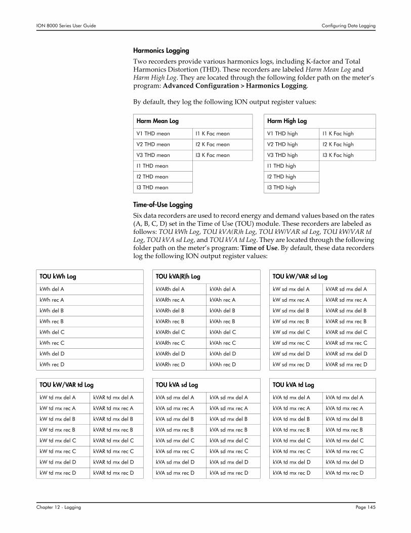
ION 8000 Series User Guide Configuring Data Logging
Chapter 12 - Logging Page 145
Harmonics Logging
Two recorders provide various harmonics logs, including K-factor and Total Harmonics Distortion (THD). These recorders are labeled Harm Mean Log and Harm High Log. They are located through the following folder path on the meter’s program: Advanced Configuration > Harmonics Logging.
By default, they log the following ION output register values:
Time-of-Use Logging
Six data recorders are used to record energy and demand values based on the rates (A, B, C, D) set in the Time of Use (TOU) module. These recorders are labeled as follows: TOU kWh Log, TOU kVA(R)h Log, TOU kW/VAR sd Log, TOU kW/VAR td Log, TOU kVA sd Log, and TOU kVA td Log. They are located through the following folder path on the meter’s program: Time of Use. By default, these data recorders log the following ION output register values:
Harm Mean Log Harm High Log
V1 THD mean I1 K Fac mean V1 THD high I1 K Fac high
V2 THD mean I2 K Fac mean V2 THD high I2 K Fac high
V3 THD mean I3 K Fac mean V3 THD high I3 K Fac high
I1 THD mean I1 THD high
I2 THD mean I2 THD high
I3 THD mean I3 THD high
TOU kWh Log TOU kVA(R)h Log TOU kW/VAR sd Log
kWh del A kVARh del A kVAh del A kW sd mx del A kVAR sd mx del A
kWh rec A kVARh rec A kVAh rec A kW sd mx rec A kVAR sd mx rec A
kWh del B kVARh del B kVAh del B kW sd mx del B kVAR sd mx del B
kWh rec B kVARh rec B kVAh rec B kW sd mx rec B kVAR sd mx rec B
kWh del C kVARh del C kVAh del C kW sd mx del C kVAR sd mx del C
kWh rec C kVARh rec C kVAh rec C kW sd mx rec C kVAR sd mx rec C
kWh del D kVARh del D kVAh del D kW sd mx del D kVAR sd mx del D
kWh rec D kVARh rec D kVAh rec D kW sd mx rec D kVAR sd mx rec D
TOU kW/VAR td Log TOU kVA sd Log TOU kVA td Log
kW td mx del A kVAR td mx del A kVA sd mx del A kVA sd mx del A kVA td mx del A kVA td mx del A
kW td mx rec A kVAR td mx rec A kVA sd mx rec A kVA sd mx rec A kVA td mx rec A kVA td mx rec A
kW td mx del B kVAR td mx del B kVA sd mx del B kVA sd mx del B kVA td mx del B kVA td mx del B
kW td mx rec B kVAR td mx rec B kVA sd mx rec B kVA sd mx rec B kVA td mx rec B kVA td mx rec B
kW td mx del C kVAR td mx del C kVA sd mx del C kVA sd mx del C kVA td mx del C kVA td mx del C
kW td mx rec C kVAR td mx rec C kVA sd mx rec C kVA sd mx rec C kVA td mx rec C kVA td mx rec C
kW td mx del D kVAR td mx del D kVA sd mx del D kVA sd mx del D kVA td mx del D kVA td mx del D
kW td mx rec D kVAR td mx rec D kVA sd mx rec D kVA sd mx rec D kVA td mx rec D kVA td mx rec D
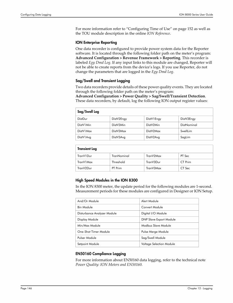
Configuring Data Logging ION 8000 Series User Guide
Page 146 Chapter 12 - Logging
For more information refer to “Configuring Time of Use” on page 152 as well as the TOU module description in the online ION Reference.
ION Enterprise Reporting
One data recorder is configured to provide power system data for the Reporter software. It is located through the following folder path on the meter’s program: Advanced Configuration > Revenue Framework > Reporting. This recorder is labeled Egy Dmd Log. If any input links to this module are changed, Reporter will not be able to create reports from the device’s logs. If you use Reporter, do not change the parameters that are logged in the Egy Dmd Log.
Sag/Swell and Transient Logging
Two data recorders provide details of these power quality events. They are located through the following folder path on the meter’s program:Advanced Configuration > Power Quality > Sag/Swell/Transient Detection. These data recorders, by default, log the following ION output register values:
High Speed Modules in the ION 8300
In the ION 8300 meter, the update period for the following modules are 1-second. Measurement periods for these modules are configured in Designer or ION Setup.
EN50160 Compliance Logging
For more information about EN50160 data logging, refer to the technical note Power Quality: ION Meters and EN50160.
Sag/Swell Log
DistDur DistV2Engy DistV1Engy DistV3Engy
DistV1Min DistV3Min DistV2Min DistNominal
DistV1Max DistV3Max DistV2Max SwellLim
DistV1Avg DistV3Avg DistV2Avg SagLim
Transient Log
TranV1Dur TranNominal TranV2Max PT Sec
TranV1Max Threshold TranV3Dur CT Prim
TranV2Dur PT Prim TranV3Max CT Sec
And/Or Module Alert Module
Bin Module Convert Module
Disturbance Analyzer Module Digital I/O Module
Display Module DNP Slave Export Module
Min/Max Module Modbus Slave Module
One-Shot Timer Module Pulse Merge Module
Pulser Module Sag/Swell Module
Setpoint Module Voltage Selection Module
Page 147
13 RevenueThis chapter provides instructions for configuring transformer line loss compensation and time of use.
In this chapter
PT/CT Correction . . . . . . . . . . . . . . . . . . . . . . . . . . . . . . . . . . . . . . . . . . 148Configuring PT/CT Correction . . . . . . . . . . . . . . . . . . . . . . . . . . . . . . . . . . . . . . . . 148
Using ION Setup ................................................................................................. 148
Transformer Line Loss Compensation (TLC) . . . . . . . . . . . . . . . . . . . . . . . . 149Configuring TLC . . . . . . . . . . . . . . . . . . . . . . . . . . . . . . . . . . . . . . . . . . . . . . . . . . . . 149
Using the Front Panel ......................................................................................... 149Using ION Setup ................................................................................................. 149Using Vista ........................................................................................................... 150
Time of Use 152Configuring Time of Use . . . . . . . . . . . . . . . . . . . . . . . . . . . . . . . . . . . . . . . . . . . . . 152
Using the Front Panel ......................................................................................... 152Using ION Setup ................................................................................................. 152Using Designer .................................................................................................... 152
Time Of Use Module Settings . . . . . . . . . . . . . . . . . . . . . . . . . . . . . . . . . . . . . . . . . 153Seasonal Settings ................................................................................................. 153
Creating a New Time Of Use Schedule . . . . . . . . . . . . . . . . . . . . . . . . . . . . . . . . . 154Displaying Time of Use . . . . . . . . . . . . . . . . . . . . . . . . . . . . . . . . . . . . . . . . . . . . . . . 154
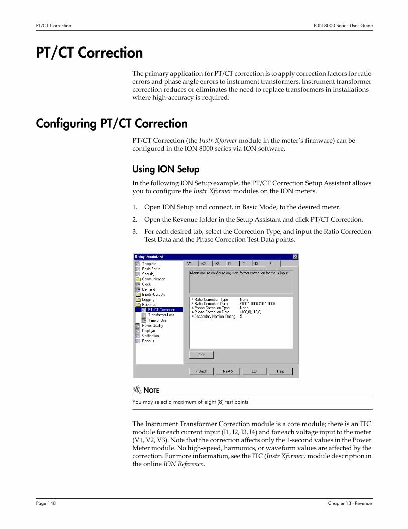
PT/CT Correction ION 8000 Series User Guide
Page 148 Chapter 13 - Revenue
PT/CT CorrectionThe primary application for PT/CT correction is to apply correction factors for ratio errors and phase angle errors to instrument transformers. Instrument transformer correction reduces or eliminates the need to replace transformers in installations where high-accuracy is required.
Configuring PT/CT CorrectionPT/CT Correction (the Instr Xformer module in the meter’s firmware) can be configured in the ION 8000 series via ION software.
Using ION SetupIn the following ION Setup example, the PT/CT Correction Setup Assistant allows you to configure the Instr Xformer modules on the ION meters.
1. Open ION Setup and connect, in Basic Mode, to the desired meter.
2. Open the Revenue folder in the Setup Assistant and click PT/CT Correction.
3. For each desired tab, select the Correction Type, and input the Ratio Correction Test Data and the Phase Correction Test Data points.
NOTE
You may select a maximum of eight (8) test points.
The Instrument Transformer Correction module is a core module; there is an ITC module for each current input (I1, I2, I3, I4) and for each voltage input to the meter (V1, V2, V3). Note that the correction affects only the 1-second values in the Power Meter module. No high-speed, harmonics, or waveform values are affected by the correction. For more information, see the ITC (Instr Xformer) module description in the online ION Reference.
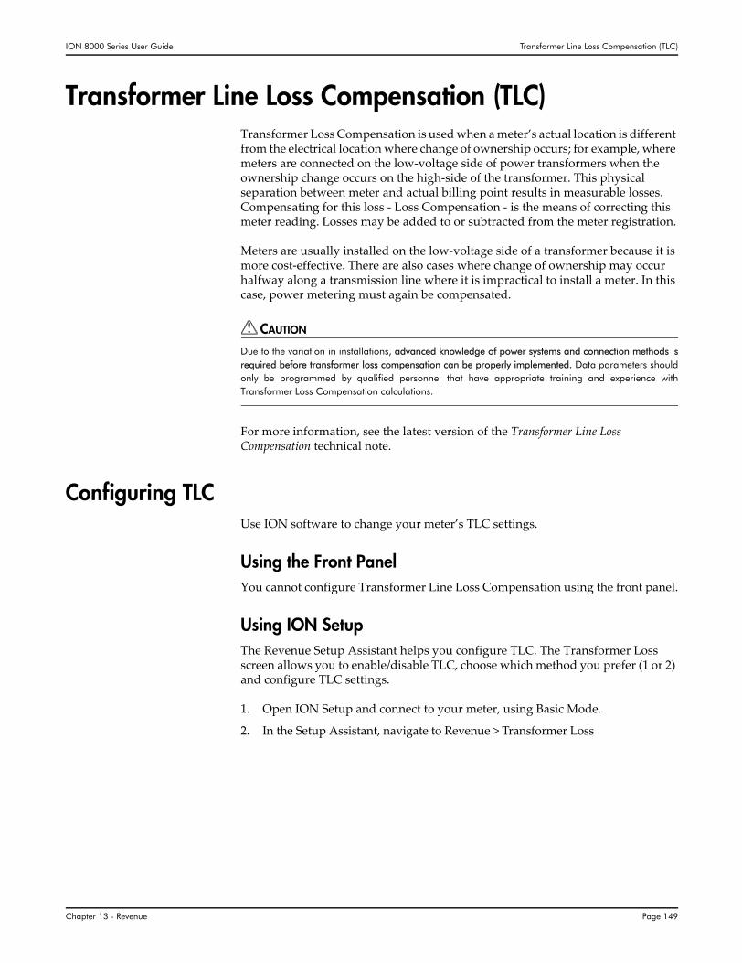
ION 8000 Series User Guide Transformer Line Loss Compensation (TLC)
Chapter 13 - Revenue Page 149
Transformer Line Loss Compensation (TLC)Transformer Loss Compensation is used when a meter’s actual location is different from the electrical location where change of ownership occurs; for example, where meters are connected on the low-voltage side of power transformers when the ownership change occurs on the high-side of the transformer. This physical separation between meter and actual billing point results in measurable losses. Compensating for this loss - Loss Compensation - is the means of correcting this meter reading. Losses may be added to or subtracted from the meter registration.
Meters are usually installed on the low-voltage side of a transformer because it is more cost-effective. There are also cases where change of ownership may occur halfway along a transmission line where it is impractical to install a meter. In this case, power metering must again be compensated.
CAUTION
Due to the variation in installations, advanced knowledge of power systems and connection methods isrequired before transformer loss compensation can be properly implemented. Data parameters shouldonly be programmed by qualified personnel that have appropriate training and experience withTransformer Loss Compensation calculations.
For more information, see the latest version of the Transformer Line Loss Compensation technical note.
Configuring TLCUse ION software to change your meter’s TLC settings.
Using the Front PanelYou cannot configure Transformer Line Loss Compensation using the front panel.
Using ION SetupThe Revenue Setup Assistant helps you configure TLC. The Transformer Loss screen allows you to enable/disable TLC, choose which method you prefer (1 or 2) and configure TLC settings.
1. Open ION Setup and connect to your meter, using Basic Mode.
2. In the Setup Assistant, navigate to Revenue > Transformer Loss
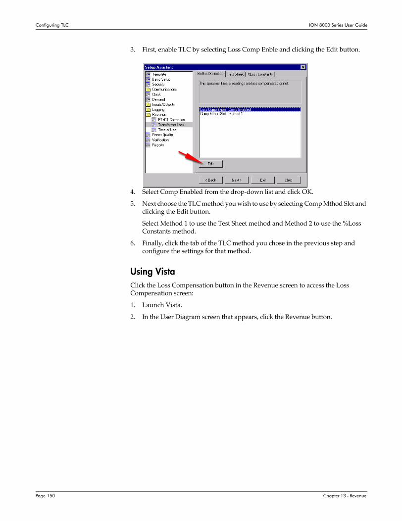
Configuring TLC ION 8000 Series User Guide
Page 150 Chapter 13 - Revenue
3. First, enable TLC by selecting Loss Comp Enble and clicking the Edit button.
4. Select Comp Enabled from the drop-down list and click OK.
5. Next choose the TLC method you wish to use by selecting Comp Mthod Slct and clicking the Edit button.
Select Method 1 to use the Test Sheet method and Method 2 to use the %Loss Constants method.
6. Finally, click the tab of the TLC method you chose in the previous step and configure the settings for that method.
Using VistaClick the Loss Compensation button in the Revenue screen to access the Loss Compensation screen:
1. Launch Vista.
2. In the User Diagram screen that appears, click the Revenue button.
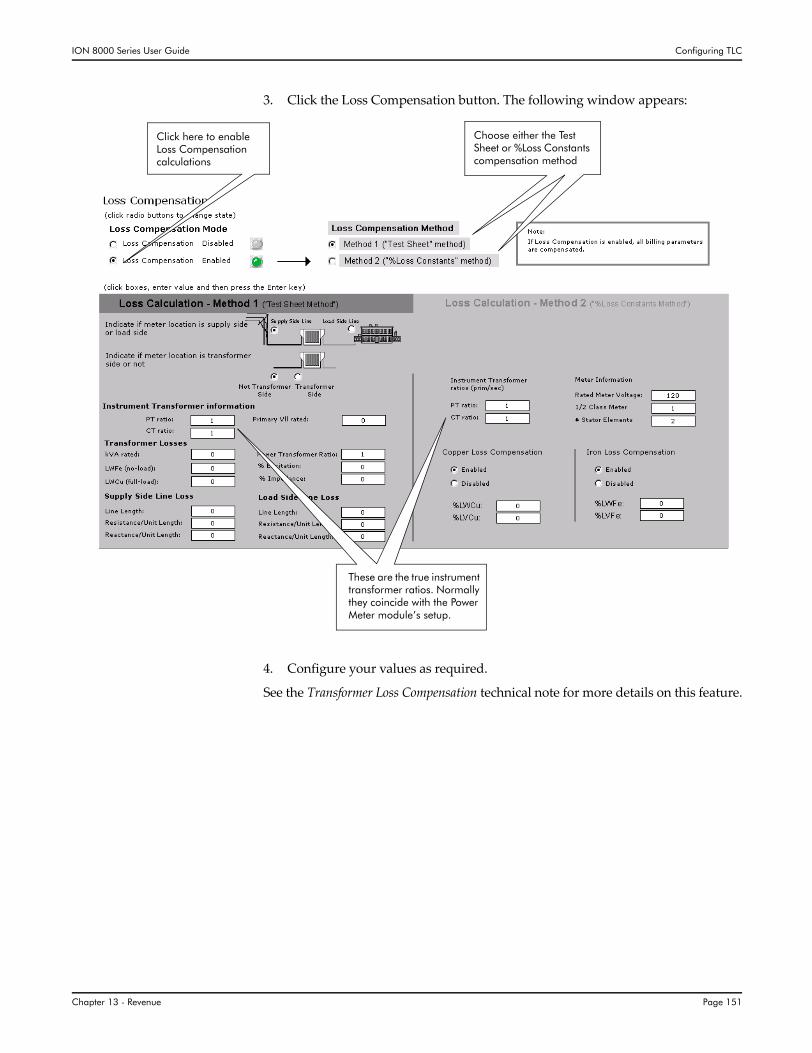
ION 8000 Series User Guide Configuring TLC
Chapter 13 - Revenue Page 151
3. Click the Loss Compensation button. The following window appears:
4. Configure your values as required.
See the Transformer Loss Compensation technical note for more details on this feature.
Click here to enable Loss Compensation calculations
Choose either the Test Sheet or %Loss Constants compensation method
These are the true instrument transformer ratios. Normally they coincide with the Power Meter module’s setup.
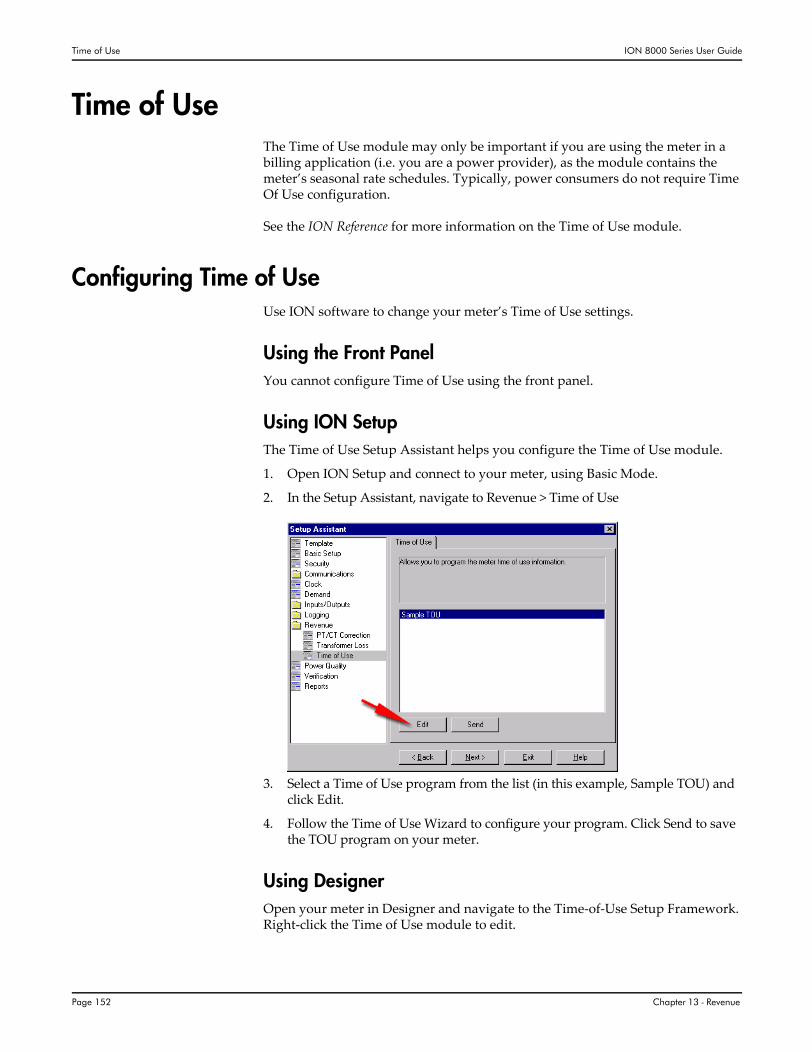
Time of Use ION 8000 Series User Guide
Page 152 Chapter 13 - Revenue
Time of UseThe Time of Use module may only be important if you are using the meter in a billing application (i.e. you are a power provider), as the module contains the meter’s seasonal rate schedules. Typically, power consumers do not require Time Of Use configuration.
See the ION Reference for more information on the Time of Use module.
Configuring Time of UseUse ION software to change your meter’s Time of Use settings.
Using the Front PanelYou cannot configure Time of Use using the front panel.
Using ION SetupThe Time of Use Setup Assistant helps you configure the Time of Use module.
1. Open ION Setup and connect to your meter, using Basic Mode.
2. In the Setup Assistant, navigate to Revenue > Time of Use
3. Select a Time of Use program from the list (in this example, Sample TOU) and click Edit.
4. Follow the Time of Use Wizard to configure your program. Click Send to save the TOU program on your meter.
Using DesignerOpen your meter in Designer and navigate to the Time-of-Use Setup Framework. Right-click the Time of Use module to edit.
ION 8000 Series User Guide Time Of Use Module Settings
Chapter 13 - Revenue Page 153
Time Of Use Module SettingsThe Time of Use module’s setup registers define your seasons’ start and end dates, the day types where your rates may differ, and the rate schedules for each season’s day types. The module compares the meter’s internal clock with the season, day, and time of day settings in these registers, and changes its output registers to reflect the current state of these settings.
Seasonal SettingsThe Time of Use module supports up to four separate seasons. Each seasons’ start and end dates are set into the appropriate Season setup register.
NOTE
Ensure that there is no date overlapping when defining seasons and that every day of the year is coveredby your seasons. If there are gaps between seasons, the module returns an error and will not function.
If your rates do not change between seasons, you do not need to configure the Season setup registers — Season 1 is the default, and all Season 1 rates are in effect all year.
If you have different seasons, enter their start and end dates into the appropriate setup registers. If your season is active on the same dates every year, you only need to enter a single range of dates in the appropriate Season setup register. If the active dates are different each year (for example, Season 3 becomes active every first Monday in August), the start dates must be individually specified for each year.
The Time of Use module is partially configured at the factory. Check the setup registers to ensure that the settings match your Time of Use schedules.
Setup Register Function
Season 1- 4 These setup registers define the dates for each active season. When a season is active, the Time of Use module will use the applicable rate schedules.
Season 1 - 4Weekday Rates These setup registers specify seasonal weekday rates.
Season 1 - 4Weekend Rates These setup registers specify seasonal weekend rates.
Season 1 - 4Alt 1 Rates These setup registers specify a season's daily rates during the days specified in the Alt 1 Days setup register.
Season 1 - 4Alt 2 Rates These setup registers specify a season's daily rates during the days specified in the Alt 2 Days setup register.
Season 1 - 4Holiday Rates These setup registers specify a season's daily rates during the days specified in the Holidays setup register.
Weekdays This register defines the days of the week for all seasons. The rates in the Season (1, 2, 3, or 4) Weekday Rates setup registers are used on these days.
Weekends This register defines the weekend days for all seasons. The rates in the Season (1, 2, 3, or 4) Weekend Rates setup registers are used on these days.
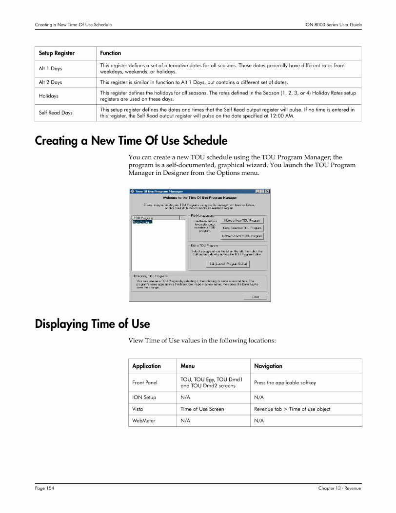
Creating a New Time Of Use Schedule ION 8000 Series User Guide
Page 154 Chapter 13 - Revenue
Creating a New Time Of Use ScheduleYou can create a new TOU schedule using the TOU Program Manager; the program is a self-documented, graphical wizard. You launch the TOU Program Manager in Designer from the Options menu.
Displaying Time of UseView Time of Use values in the following locations:
Alt 1 Days This register defines a set of alternative dates for all seasons. These dates generally have different rates from weekdays, weekends, or holidays.
Alt 2 Days This register is similar in function to Alt 1 Days, but contains a different set of dates.
Holidays This register defines the holidays for all seasons. The rates defined in the Season (1, 2, 3, or 4) Holiday Rates setup registers are used on these days.
Self Read Days This setup register defines the dates and times that the Self Read output register will pulse. If no time is entered in this register, the Self Read output register will pulse on the date specified at 12:00 AM.
Setup Register Function
Application Menu Navigation
Front Panel TOU, TOU Egy, TOU Dmd1 and TOU Dmd2 screens
Press the applicable softkey
ION Setup N/A N/A
Vista Time of Use Screen Revenue tab > Time of use object
WebMeter N/A N/A

ION 8000 Series User Guide Displaying Time of Use
Chapter 13 - Revenue Page 155

Page 157
14 Power QualityThis chapter explains how to configure your meter’s power quality functionality.
In this chapter
Introduction . . . . . . . . . . . . . . . . . . . . . . . . . . . . . . . . . . . . . . . . . . . . . . 158
Configuring Power Quality . . . . . . . . . . . . . . . . . . . . . . . . . . . . . . . . . . . 158Using the Front Panel ......................................................................................... 158Using ION Setup ................................................................................................. 158Using Designer .................................................................................................... 159
Sag/Swell Module Settings . . . . . . . . . . . . . . . . . . . . . . . . . . . . . . . . . . . . . . . . . . . . 159Transient Module Settings (ION 8500 only) . . . . . . . . . . . . . . . . . . . . . . . . . . . . . 160
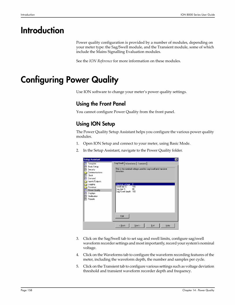
Introduction ION 8000 Series User Guide
Page 158 Chapter 14 - Power Quality
IntroductionPower quality configuration is provided by a number of modules, depending on your meter type: the Sag/Swell module, and the Transient module, some of which include the Mains Signalling Evaluation modules.
See the ION Reference for more information on these modules.
Configuring Power QualityUse ION software to change your meter’s power quality settings.
Using the Front PanelYou cannot configure Power Quality from the front panel.
Using ION SetupThe Power Quality Setup Assistant helps you configure the various power quality modules.
1. Open ION Setup and connect to your meter, using Basic Mode.
2. In the Setup Assistant, navigate to the Power Quality folder.
3. Click on the Sag/Swell tab to set sag and swell limits, configure sag/swell waveform recorder settings and most importantly, record your system’s nominal voltage.
4. Click on the Waveforms tab to configure the waveform recording features of the meter, including the waveform depth, the number and samples per cycle.
5. Click on the Transient tab to configure various settings such as voltage deviation threshold and transient waveform recorder depth and frequency.
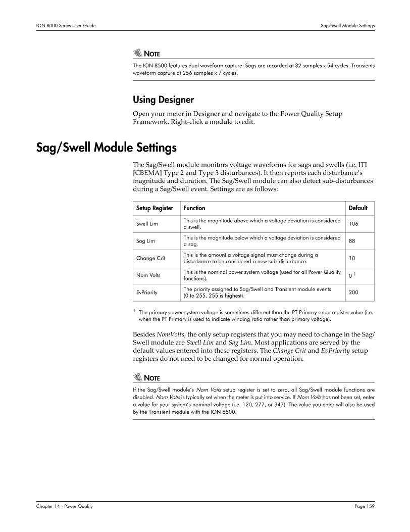
ION 8000 Series User Guide Sag/Swell Module Settings
Chapter 14 - Power Quality Page 159
NOTE
The ION 8500 features dual waveform capture: Sags are recorded at 32 samples x 54 cycles. Transientswaveform capture at 256 samples x 7 cycles.
Using DesignerOpen your meter in Designer and navigate to the Power Quality Setup Framework. Right-click a module to edit.
Sag/Swell Module SettingsThe Sag/Swell module monitors voltage waveforms for sags and swells (i.e. ITI [CBEMA] Type 2 and Type 3 disturbances). It then reports each disturbance’s magnitude and duration. The Sag/Swell module can also detect sub-disturbances during a Sag/Swell event. Settings are as follows:
1 The primary power system voltage is sometimes different than the PT Primary setup register value (i.e. when the PT Primary is used to indicate winding ratio rather than primary voltage).
Besides NomVolts, the only setup registers that you may need to change in the Sag/Swell module are Swell Lim and Sag Lim. Most applications are served by the default values entered into these registers. The Change Crit and EvPriority setup registers do not need to be changed for normal operation.
NOTE
If the Sag/Swell module’s Nom Volts setup register is set to zero, all Sag/Swell module functions aredisabled. Nom Volts is typically set when the meter is put into service. If Nom Volts has not been set, entera value for your system’s nominal voltage (i.e. 120, 277, or 347). The value you enter will also be usedby the Transient module with the ION 8500.
Setup Register Function Default
Swell Lim This is the magnitude above which a voltage deviation is considered a swell.
106
Sag Lim This is the magnitude below which a voltage deviation is considered a sag.
88
Change CritThis is the amount a voltage signal must change during a disturbance to be considered a new sub-disturbance. 10
Nom VoltsThis is the nominal power system voltage (used for all Power Quality functions). 0 1
EvPriorityThe priority assigned to Sag/Swell and Transient module events (0 to 255, 255 is highest). 200
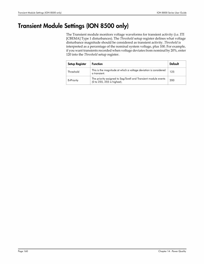
Transient Module Settings (ION 8500 only) ION 8000 Series User Guide
Page 160 Chapter 14 - Power Quality
Transient Module Settings (ION 8500 only)The Transient module monitors voltage waveforms for transient activity (i.e. ITI [CBEMA] Type 1 disturbances). The Threshold setup register defines what voltage disturbance magnitude should be considered as transient activity. Threshold is interpreted as a percentage of the nominal system voltage, plus 100. For example, if you want transients recorded when voltage deviates from nominal by 20%, enter 120 into the Threshold setup register.
Setup Register Function Default
ThresholdThis is the magnitude at which a voltage deviation is considered a transient. 125
EvPriorityThe priority assigned to Sag/Swell and Transient module events (0 to 255, 255 is highest). 200
Page 161
15 DisplaysThis chapter explains the available front panel displays. It also includes procedures for customizing displays using ION software.
In this chapter
Introduction . . . . . . . . . . . . . . . . . . . . . . . . . . . . . . . . . . . . . . . . . . . . . . 162
Configuring Front Panel Displays . . . . . . . . . . . . . . . . . . . . . . . . . . . . . . . 163Using the front panel .......................................................................................... 163Using ION Setup ................................................................................................. 163Using Designer .................................................................................................... 164
Default Front Panel Display Screens . . . . . . . . . . . . . . . . . . . . . . . . . . . . . 167NORM mode display screens ............................................................................ 167ALT mode default display screens ................................................................... 168TEST mode default display screens .................................................................. 171
Introduction ION 8000 Series User Guide
Page 162 Chapter 15 - Displays
IntroductionThe ION 8000 series ships with preconfigured display screens designed to suit the data needs of most users. Different types of screens are available depending upon the meter’s current mode of operation (see “Modes of Operation” on page 25 for details).
Front panel displays may also be customized on your meter to show virtually any measurement or calculation. For example, you could do one or all of the following:
change displayed parameters, such as from Vll to Vln or Vllab to Vlna
adjust character size to be different on each screen
change data display settings such as backlight timeout, automatic display scrolling, parameter update rate and display mode*
Use ION software to customize your front panel display screens.
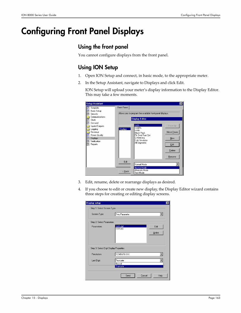
ION 8000 Series User Guide Configuring Front Panel Displays
Chapter 15 - Displays Page 163
Configuring Front Panel Displays
Using the front panelYou cannot configure displays from the front panel.
Using ION Setup1. Open ION Setup and connect, in basic mode, to the appropriate meter.
2. In the Setup Assistant, navigate to Displays and click Edit.
ION Setup will upload your meter’s display information to the Display Editor. This may take a few moments.
3. Edit, rename, delete or rearrange displays as desired.
4. If you choose to edit or create new display, the Display Editor wizard contains three steps for creating or editing display screens.
Configuring Front Panel Displays ION 8000 Series User Guide
Page 164 Chapter 15 - Displays
Choose the screen type
Select the parameters available for your chosen screen type
Select your display qualities, including digit resolution and truncated or rounded last digits.
5. Click Send to save the changes in the meter.
Using Designer
CAUTION
Before you reconfigure or delete a framework, you should make a copy. This ensures that you can restorethe framework without having to reinitialize the factory configuration.
To remove a data display screen:
1. Launch Designer.
2. Select the Display module responsible for the screen.
3. Press delete. This also deletes all links to that particular Display module.
If the display screen you are deleting is part of the automatic scrolling cycle, you should reconfigure the links from the Scroll module’s Trigger outputs to the remaining Display modules so that the following considerations hold true:
The first Display module in the scrolling cycle is linked to the Trigger 1 output of the Scroll module.
The last Display module in the scrolling cycle (module n) is linked to the Trigger n output of the Scroll module. For example, if your scrolling cycle consists of 5 screens, then Trigger 5 should be linked to the fifth module in the cycle.
The Wraparound setup register of the Scroll module designates the last trigger output (Trigger n). Expanding on the previous example, since Trigger 5 is the last trigger, the Scroll module’s Wraparound setup register would have a value of 5.
To add a new display screen
1. Create a Display module.
2. Define the modules characteristics (display format) by adjusting its setup registers.
3. Link any required data to the Source inputs of the Display module.
If you want your new screen to appear in the automatic scrolling cycle, then you must link the Show input of the Display module to a Trigger output of a Scroll module.
To create a Disk Simulator screen
1. Create a new Display module, and choose the type as Disk Simulator.
2. Connect the new Display module’s first input to the Calibration Pulser module’s Disk Position output that you want to monitor for its pulsing interval.
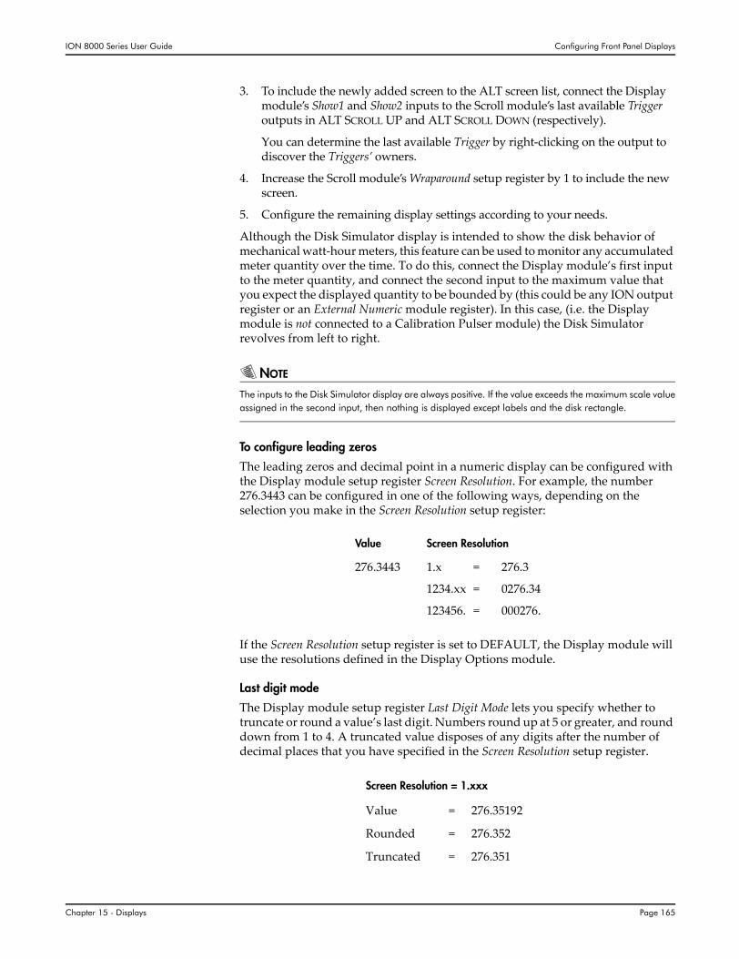
ION 8000 Series User Guide Configuring Front Panel Displays
Chapter 15 - Displays Page 165
3. To include the newly added screen to the ALT screen list, connect the Display module’s Show1 and Show2 inputs to the Scroll module’s last available Trigger outputs in ALT SCROLL UP and ALT SCROLL DOWN (respectively).
You can determine the last available Trigger by right-clicking on the output to discover the Triggers’ owners.
4. Increase the Scroll module’s Wraparound setup register by 1 to include the new screen.
5. Configure the remaining display settings according to your needs.
Although the Disk Simulator display is intended to show the disk behavior of mechanical watt-hour meters, this feature can be used to monitor any accumulated meter quantity over the time. To do this, connect the Display module’s first input to the meter quantity, and connect the second input to the maximum value that you expect the displayed quantity to be bounded by (this could be any ION output register or an External Numeric module register). In this case, (i.e. the Display module is not connected to a Calibration Pulser module) the Disk Simulator revolves from left to right.
NOTE
The inputs to the Disk Simulator display are always positive. If the value exceeds the maximum scale valueassigned in the second input, then nothing is displayed except labels and the disk rectangle.
To configure leading zeros
The leading zeros and decimal point in a numeric display can be configured with the Display module setup register Screen Resolution. For example, the number 276.3443 can be configured in one of the following ways, depending on the selection you make in the Screen Resolution setup register:
If the Screen Resolution setup register is set to DEFAULT, the Display module will use the resolutions defined in the Display Options module.
Last digit mode
The Display module setup register Last Digit Mode lets you specify whether to truncate or round a value’s last digit. Numbers round up at 5 or greater, and round down from 1 to 4. A truncated value disposes of any digits after the number of decimal places that you have specified in the Screen Resolution setup register.
Value Screen Resolution
276.3443 1.x = 276.3
1234.xx = 0276.34
123456. = 000276.
Screen Resolution = 1.xxx
Value = 276.35192
Rounded = 276.352
Truncated = 276.351

Configuring Front Panel Displays ION 8000 Series User Guide
Page 166 Chapter 15 - Displays
To configure parameter titles
The parameter value on a display screen is the value of an output connected to the Display module Source input register. By default, the displayed parameter’s title is the name of the output connected to the Source input. The Display module Source Title setup register lets you change the default to a title that better describes your system. For example, if “KWh Net” is linked to the first Source input, you could change its display name by setting Source 1 Title to “KWh Net West.” A maximum of 25 characters is permitted.
See “Changing TEST Mode Timeout” on page 178 for information on configuring TEST mode display timeouts.
ION 8000 Series User Guide Default Front Panel Display Screens
Chapter 15 - Displays Page 167
Default Front Panel Display ScreensEach mode of operation (NORM, ALT and TEST) has its own display screens, providing various power system data and meter properties screens.
NORM mode display screensThe factory-configured ION 8000 series meter scrolls through nine displays detailed below. If the settings in the Scroll module have not been altered, each screen is displayed for five seconds if no front panel buttons are pressed.
Display scrolling is suspended when a front panel button is pressed, and you can manually scroll through the display screens using the Up or Down arrow buttons. If required, refer to “Front Panel Features” on page 18 for more instructions on using the front panel buttons.
1. kWh
This screen displays kWh delivered and received values.
2. kVARh
This screen displays kVARh delivered and received values.
3. kVAh
This screen displays kVAh delivered and received values.
4. Peak Demand Delivered
This screen displays the maximum delivered kW value and a timestamp of when the peak occurred. This value is a Sliding Window (Rolling Block) demand calculation.
5. Peak Demand Received
This screen displays the maximum received kW value and a timestamp of when the peak occurred. This value is a Sliding Window (Rolling Block) demand calculation.
6. Peak Demand Reset Count
This screen displays a count of the number of Demand Resets executed as well as a timestamp of the latest Peak Demand Reset.
7. Q Metering
This screen displays approximated VARh measurements, one phase (60 degrees) behind the normal watthour connection (90° - 330° and 150° - 270°).
8. Disk Simulator
This display simulates the behavior of a mechanical watt-hour meter indicating power received or delivered by the direction of the pulse.
9. All Segments
This is a screen test where a black screen showing all segments (all pixels on) indicates that the display is functioning properly.
Default Front Panel Display Screens ION 8000 Series User Guide
Page 168 Chapter 15 - Displays
ALT mode default display screensThe factory-configured ION 8000 series meter scrolls through the following ALT mode displays. If the settings in the Scroll module have not been altered, each screen is displayed for five seconds if no front panel buttons are pressed (until five minutes have elapsed).
Viewing ALT display modes
1. Press the Alt/Enter button once to toggle between the NORM and ALT display modes.
2. Press the Up or Down arrow buttons to scroll back or forth through the displays.
If no buttons are pressed the meter reverts back to NORM mode after five minutes.
NOTE
These screens vary depending on the firmware version on the meter and custom display configuration.
1. Name Plate 1
The Name Plate 1 screen contains this information:
TAG1 and TAG2 typically identify the meter’s user and installed location. The Owner and TAG registers are configurable with ION software. See “How to TAG Your Meter” on page 40.
2. Name Plate 2
This screen displays the following information for the current Sliding Window (Rolling Block) and Thermal demand settings:
1 The MAX (kW) value is a maximum allowable demand level based on installed transformer configurations and nominal voltages and currents.
3. Event Log
The Event Log screen displays up to four most recent, highest priority events (priority 255 only). The date, a timestamp, an event description, and an event code are provided for each event displayed. If more than four high priority
Owner
TAG1 from Factory module
TAG2 from Factory module
Firmware revision of the meter
Battery life indicator
Sliding Window (Rolling Block) Thermal
CONFIGLength of the demand period multiplied by the number of demand periods
Length of the demand period
UPDATE Length of the demand period Always 1 second
SYNC Clock synchronization source Always N/A
MAX (kW) Maximum kW Demand1 Maximum kW Demand1
ION 8000 Series User Guide Default Front Panel Display Screens
Chapter 15 - Displays Page 169
events have been recorded, then the Event Log screen will indicate additional logs exist. Refer to “Data Logging” on page 140 for more details.
4. Vector Diagram
This screen shows phasors and numeric values for each phase current and phase voltage measurement.
5. Instantaneous Voltage
This screen shows average voltage, line-to-neutral and/or line-to-line voltage (depending on the meter’s service type).
6. Instantaneous Current
This screen shows the phase current and average current values.
7. Instantaneous Power
This screen shows kW total, kVAR total, kVA total and signed Power Factor total values.
8. Instantaneous Demand
This screen shows kW delivered and received from the Sliding Window (Rolling Block) demand calculation.
9, 10, 11. Voltage Harmonics
These screens show histograms of the per phase voltage harmonic content.
12, 13, 14. Current Harmonics
These screens show histograms of the per phase current harmonic content.
15. Availability
This screen shows the availability of power in a “number of nines” measurement, over a pre-set period of time.
16. Instantaneous Demand
This screen shows kW td delivered and received.
ALT mode Time of Use (TOU) display screens
ALT mode display screens 17 to 56 are factory-configured to show Time of Use (TOU) data. The measurements displayed originate from frameworks of ION modules that are linked to a TOU module. For details about the TOU module, refer to the ION Reference.
By default, all demand values result from Sliding Window (Rolling Block) calculations.
17. TOU Energy by Rate
This screen shows kWh delivered values for each TOU rate.
18 - 25. kW Peak Demand
These screens display the maximum kW delivered value for each TOU rate. These values result from Sliding Window (Rolling Block) demand calculations.
26. Previous Billing Energy
Default Front Panel Display Screens ION 8000 Series User Guide
Page 170 Chapter 15 - Displays
This screen displays the kWh delivered values for each TOU rate in the previous billing period.
NOTE
PB = Previous Billing period. A billing period is the time between two consecutive meter readings forbilling purposes by a utility.
27 - 34. Prev Billing Peak Demand
These screens display the maximum kW delivered value for each TOU rate in the previous billing period. These values result from Sliding Window (Rolling Block) demand calculations.
35. Previous Season Energy
This screen displays the kWh delivered for each TOU rate in the previous billing season. These values result from Sliding Window (Rolling Block) demand calculations.
NOTE
PS = Previous Season. Billing Seasons are defined in the TOU module description in the ION Reference.
36 - 43. Prev Season Peak Demand
These screens display the maximum kW delivered for each TOU rate in the previous billing season.
44. Prev Billing/Season Energy
These screens display the kWh delivered and received values in the previous billing period and billing season.
45, 46. Prev Bill/ Season Pk Demand
These screens show the maximum kW sd received values in the previous billing period and billing season. These values result from a Sliding Window (Rolling Block) demand calculation.
47. Prev Billing/Season Energy
These screens display the kVARh delivered and received values in the previous billing period and billing season.
48, 49. Prev Bill/Season Pk Demand
These screens display the kVAR delivered and received values in the previous billing period and billing season. These values result from a Sliding Window (Rolling Block) demand calculation.
50. Prev Billing/Season Energy
These screens display the kVAh delivered and received values in the previous billing period and billing season.
51, 52. Prev Bill/Season Pk Demand
These screens display the kVA delivered and received values in the previous billing period and billing season. These values result from a Sliding Window (Rolling Block) demand calculation.
ION 8000 Series User Guide Default Front Panel Display Screens
Chapter 15 - Displays Page 171
53. Active TOU Rate
This screen shows which of the valid TOU billing rates is active.
54. Active TOU Season
This screen shows which TOU billing season is currently active.
55. Flicker
This screen displays flicker measurements from V1, V2 and V3.
56. Frequency
This screen displays frequency information.
TEST mode default display screensRecall that the values shown in the TEST mode display screens represent different accumulators than those shown in NORM mode (although they perform some of the same basic measurements). The TEST mode display values are for calibration checking purposes; they will only accumulate while the meter is in TEST mode.
Viewing TEST mode
There are two ways to switch the meter into TEST mode depending on the type of meter you have:
Standard meter (without hardware lock): You must use ION software; refer to “Switching to TEST Mode” on page 175.
Standard hardware-locked meter: You must remove the cover from the meter and press the TEST mode button; refer to “Remove the socket-sealing ring (if applicable).” on page 182 for detailed instructions on removing the meter’s cover.
Once the meter is in TEST mode the front panel cycles through four TEST mode display screens summarized below.
1. kWh Test
This screen shows TEST mode kWh delivered and received values.
2. kVARh/KVAh Test
This screen shows TEST mode kVARh/KVAh delivered and received values.
3, 4. Instantaneous Demand Test
This screen shows TEST mode kW delivered and received values. Both quantities are produced from a Sliding Window (Rolling Block) demand calculation. This value is reset if the Demand Reset switch is turned while the device is in TEST mode.

Page 173
16 TEST ModeThis chapter describes your meter’s TEST Mode and explains how to switch from Normal Mode to TEST Mode.
In this chapter
Introduction . . . . . . . . . . . . . . . . . . . . . . . . . . . . . . . . . . . . . . . . . . . . . . 174
Switching to TEST Mode . . . . . . . . . . . . . . . . . . . . . . . . . . . . . . . . . . . . . 175Using the front panel (standard meter) ............................................................ 175Using the front panel (hardware locked meter) ............................................. 175Using ION Setup (standard meter) ................................................................... 175Using ION Setup (hardware-locked meter) .................................................... 176Using Vista (standard meter) ............................................................................. 176Using Vista (hardware-locked meter) .............................................................. 177
Changing TEST Mode Timeout 178Using the front panel .......................................................................................... 178Using ION Setup ................................................................................................. 178Using Designer .................................................................................................... 179
TEST Mode Default Display Screens . . . . . . . . . . . . . . . . . . . . . . . . . . . . . 180TEST mode LED energy pulsing ....................................................................... 180
Introduction ION 8000 Series User Guide
Page 174 Chapter 16 - TEST Mode
IntroductionTEST Mode is typically used for verifying meter calibration and function. The meter is usually reading data from a test power supply while these functions are performed.
Several things to note about TEST Mode:
All of the billing quantities that are recorded when the meter is in normal mode will stop accumulating when the meter is switched to TEST Mode — the data is sent to special TEST Mode registers instead.
The values accumulated in these test registers are displayed on the front panel and in ION software.
The regular normal mode billing registers are unaffected while the meter is in TEST Mode; accumulation of this data continues as soon as you exit TEST Mode.
All test registers are reset to zero when you exit TEST Mode.
NOTE
The meter will always return to NORM mode when you exit TEST mode, even if you entered TEST modefrom ALT mode.
You cannot place a hardware-locked meter in TEST mode using ION software. The meter must be placed in TEST mode via the front panel.
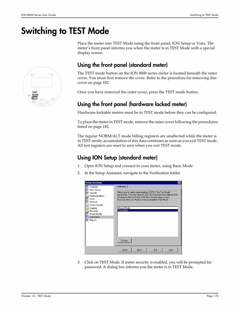
ION 8000 Series User Guide Switching to TEST Mode
Chapter 16 - TEST Mode Page 175
Switching to TEST ModePlace the meter into TEST Mode using the front panel, ION Setup or Vista. The meter’s front panel informs you when the meter is in TEST Mode with a special display screen.
Using the front panel (standard meter)The TEST mode button on the ION 8000 series meter is located beneath the outer cover. You must first remove the cover. Refer to the procedure for removing this cover on page 182.
Once you have removed the outer cover, press the TEST mode button.
Using the front panel (hardware locked meter)Hardware-lockable meters must be in TEST mode before they can be configured.
To place the meter in TEST mode, remove the outer cover following the procedures listed on page 182.
The regular NORM/ALT mode billing registers are unaffected while the meter is in TEST mode; accumulation of this data continues as soon as you exit TEST mode. All test registers are reset to zero when you exit TEST mode.
Using ION Setup (standard meter)1. Open ION Setup and connect to your meter, using Basic Mode.
2. In the Setup Assistant, navigate to the Verification folder.
3. Click on TEST Mode. If meter security is enabled, you will be prompted for password. A dialog box informs you the meter is in TEST Mode.
VAR
ENERGY
RESET
WATT
TEST
MODE
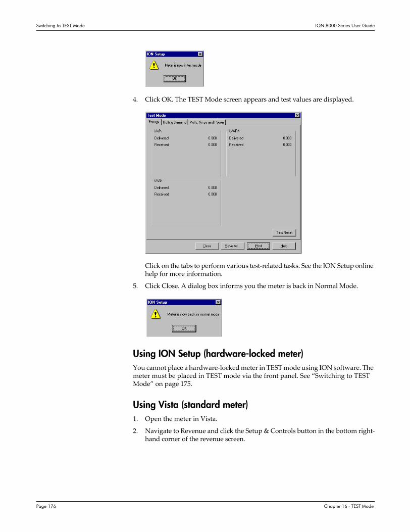
Switching to TEST Mode ION 8000 Series User Guide
Page 176 Chapter 16 - TEST Mode
4. Click OK. The TEST Mode screen appears and test values are displayed.
Click on the tabs to perform various test-related tasks. See the ION Setup online help for more information.
5. Click Close. A dialog box informs you the meter is back in Normal Mode.
Using ION Setup (hardware-locked meter)You cannot place a hardware-locked meter in TEST mode using ION software. The meter must be placed in TEST mode via the front panel. See “Switching to TEST Mode” on page 175.
Using Vista (standard meter)1. Open the meter in Vista.
2. Navigate to Revenue and click the Setup & Controls button in the bottom right-hand corner of the revenue screen.
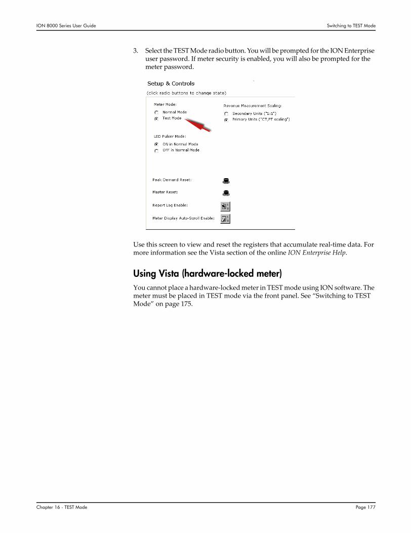
ION 8000 Series User Guide Switching to TEST Mode
Chapter 16 - TEST Mode Page 177
3. Select the TEST Mode radio button. You will be prompted for the ION Enterprise user password. If meter security is enabled, you will also be prompted for the meter password.
Use this screen to view and reset the registers that accumulate real-time data. For more information see the Vista section of the online ION Enterprise Help.
Using Vista (hardware-locked meter)You cannot place a hardware-locked meter in TEST mode using ION software. The meter must be placed in TEST mode via the front panel. See “Switching to TEST Mode” on page 175.
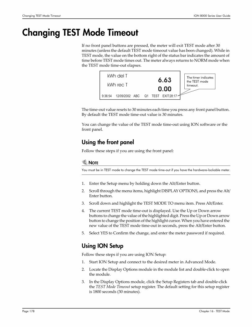
Changing TEST Mode Timeout ION 8000 Series User Guide
Page 178 Chapter 16 - TEST Mode
Changing TEST Mode TimeoutIf no front panel buttons are pressed, the meter will exit TEST mode after 30 minutes (unless the default TEST mode timeout value has been changed). While in TEST mode, the value on the bottom right of the status bar indicates the amount of time before TEST mode times out. The meter always returns to NORM mode when the TEST mode time-out elapses.
The time-out value resets to 30 minutes each time you press any front panel button. By default the TEST mode time-out value is 30 minutes.
You can change the value of the TEST mode time-out using ION software or the front panel.
Using the front panelFollow these steps if you are using the front panel:
NOTE
You must be in TEST mode to change the TEST mode time-out if you have the hardware-lockable meter.
1. Enter the Setup menu by holding down the Alt/Enter button.
2. Scroll through the menu items, highlight DISPLAY OPTIONS, and press the Alt/Enter button.
3. Scroll down and highlight the TEST MODE TO menu item. Press Alt/Enter.
4. The current TEST mode time-out is displayed. Use the Up or Down arrow buttons to change the value of the highlighted digit. Press the Up or Down arrow button to change the position of the highlight cursor. When you have entered the new value of the TEST mode time-out in seconds, press the Alt/Enter button.
5. Select YES to Confirm the change, and enter the meter password if required.
Using ION SetupFollow these steps if you are using ION Setup:
1. Start ION Setup and connect to the desired meter in Advanced Mode.
2. Locate the Display Options module in the module list and double-click to open the module.
3. In the Display Options module, click the Setup Registers tab and double-click the TEST Mode Timeout setup register. The default setting for this setup register is 1800 seconds (30 minutes).
9:36:54 12/09/2002 ABC Q1 TEST EXIT:28:17
kWh del T
6.63kWh rec T
0.00
The timer indicates the TEST mode timeout.
ION 8000 Series User Guide Changing TEST Mode Timeout
Chapter 16 - TEST Mode Page 179
4. Set the TEST Mode timeout to the desired time. You can choose from a numeric bounded format or an elapsed interval format.
5. Click SEND to transmit the changes to the meter.
Using DesignerFollow these steps if you are using Designer:
1. Open Designer and connect to the desired meter.
2. Double-click the Display Setup folder on the Designer screen.
3. Right-click on the Display Options module to access the setup registers. Select the TEST Mode Timeout setup register and click Modify to edit.
4. Set the TEST Mode timeout to the desired time. You can choose from a numeric bounded format or an elapsed interval format.
5. Click OK to send the changes to the meter.
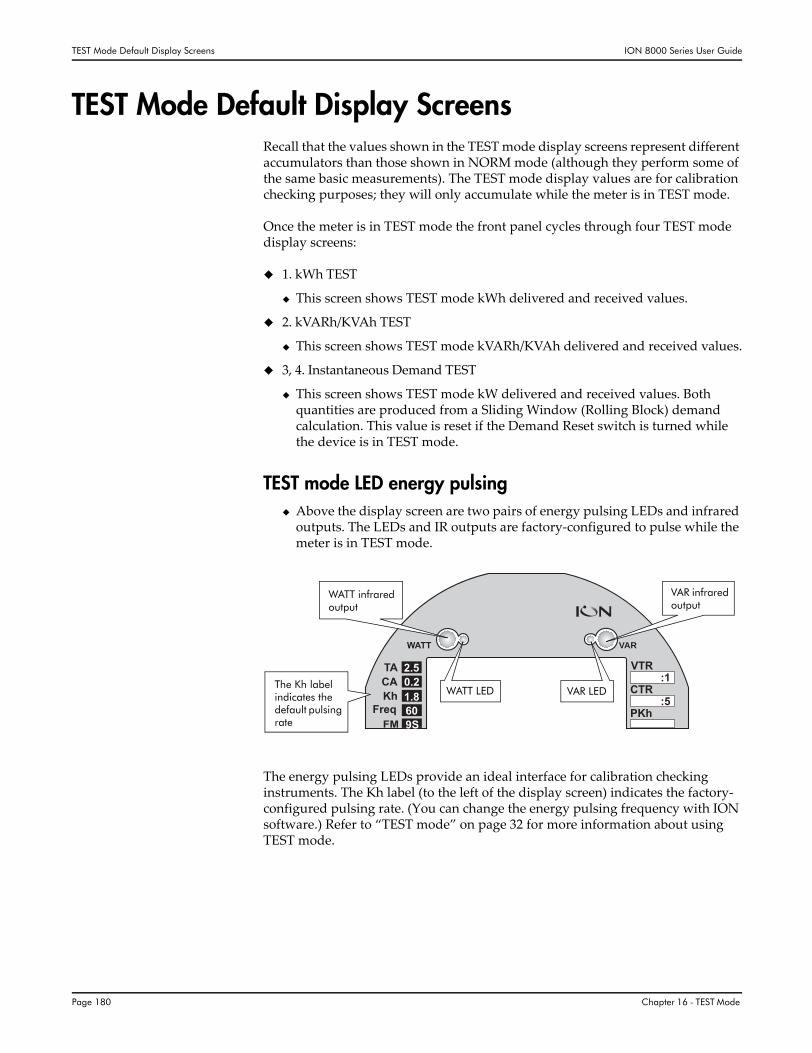
TEST Mode Default Display Screens ION 8000 Series User Guide
Page 180 Chapter 16 - TEST Mode
TEST Mode Default Display ScreensRecall that the values shown in the TEST mode display screens represent different accumulators than those shown in NORM mode (although they perform some of the same basic measurements). The TEST mode display values are for calibration checking purposes; they will only accumulate while the meter is in TEST mode.
Once the meter is in TEST mode the front panel cycles through four TEST mode display screens:
1. kWh TEST
This screen shows TEST mode kWh delivered and received values.
2. kVARh/KVAh TEST
This screen shows TEST mode kVARh/KVAh delivered and received values.
3, 4. Instantaneous Demand TEST
This screen shows TEST mode kW delivered and received values. Both quantities are produced from a Sliding Window (Rolling Block) demand calculation. This value is reset if the Demand Reset switch is turned while the device is in TEST mode.
TEST mode LED energy pulsingAbove the display screen are two pairs of energy pulsing LEDs and infrared outputs. The LEDs and IR outputs are factory-configured to pulse while the meter is in TEST mode.
The energy pulsing LEDs provide an ideal interface for calibration checking instruments. The Kh label (to the left of the display screen) indicates the factory-configured pulsing rate. (You can change the energy pulsing frequency with ION software.) Refer to “TEST mode” on page 32 for more information about using TEST mode.
CTR
PKh
WATT VAR
VTR:1
:5
Multifunction Watthour/Varhour Meter
Freq
TA
CA
FM
Kh
2.5
0.2
1.8
60
9S
WATT infrared output
VAR infrared output
VAR LEDWATT LEDThe Kh label indicates the default pulsing rate
Page 181
17 ResetsThis chapter provides instructions for performing various meter resets.
In this chapter
Performing a Reset . . . . . . . . . . . . . . . . . . . . . . . . . . . . . . . . . . . . . . . . . 182Using the Front Panel . . . . . . . . . . . . . . . . . . . . . . . . . . . . . . . . . . . . . . . . . . . . . . . . 182
Performing a Master Reset from the front panel ............................................ 182Parameters affected by a Master Reset ............................................................. 183Performing a Demand Reset from the front panel ......................................... 184Parameters affected by a Demand Reset .......................................................... 184
Using ION Setup . . . . . . . . . . . . . . . . . . . . . . . . . . . . . . . . . . . . . . . . . . . . . . . . . . . . 185Using Vista . . . . . . . . . . . . . . . . . . . . . . . . . . . . . . . . . . . . . . . . . . . . . . . . . . . . . . . . . 186
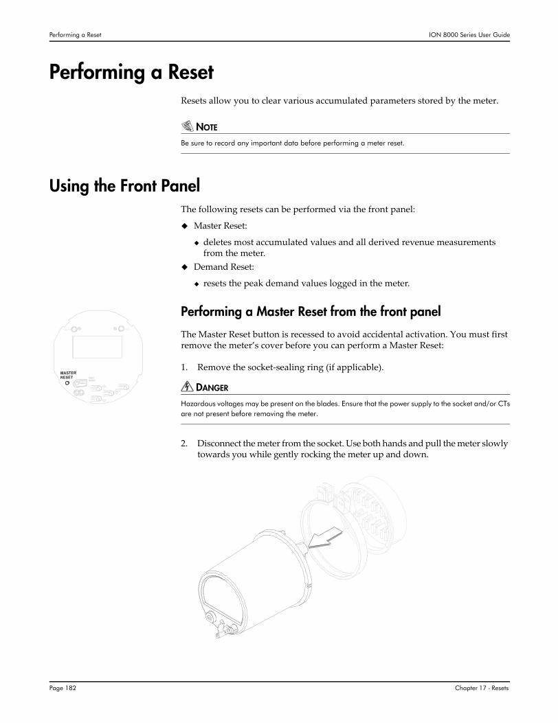
Performing a Reset ION 8000 Series User Guide
Page 182 Chapter 17 - Resets
Performing a ResetResets allow you to clear various accumulated parameters stored by the meter.
NOTE
Be sure to record any important data before performing a meter reset.
Using the Front PanelThe following resets can be performed via the front panel:
Master Reset:
deletes most accumulated values and all derived revenue measurements from the meter.
Demand Reset:
resets the peak demand values logged in the meter.
Performing a Master Reset from the front panel
The Master Reset button is recessed to avoid accidental activation. You must first remove the meter’s cover before you can perform a Master Reset:
1. Remove the socket-sealing ring (if applicable).
DANGER
Hazardous voltages may be present on the blades. Ensure that the power supply to the socket and/or CTsare not present before removing the meter.
2. Disconnect the meter from the socket. Use both hands and pull the meter slowly towards you while gently rocking the meter up and down.
VAR
MASTERRESET
WATT
TEST
MODE
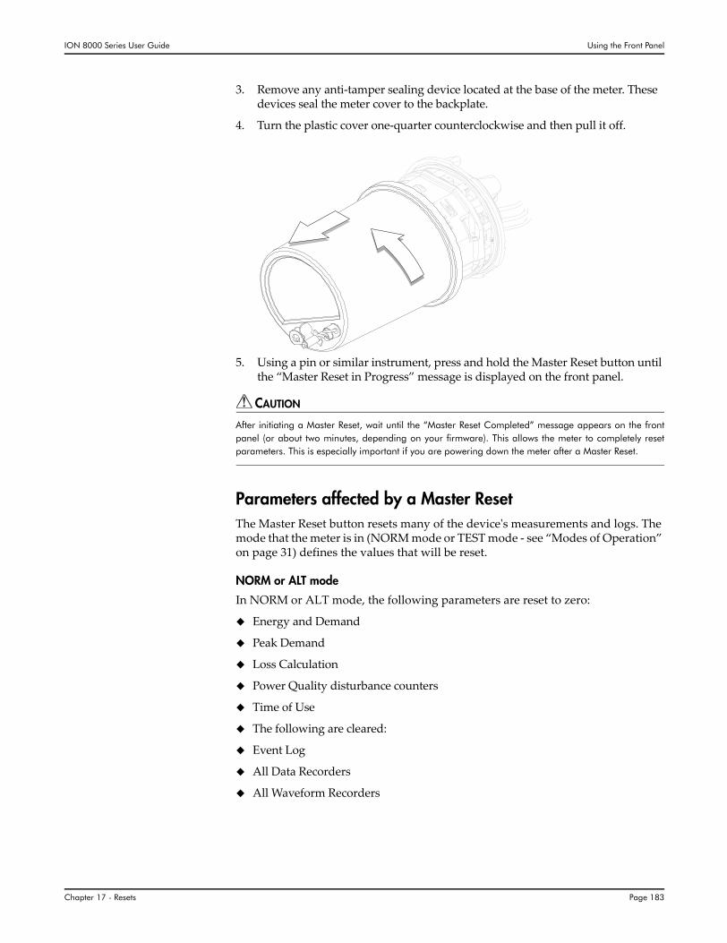
ION 8000 Series User Guide Using the Front Panel
Chapter 17 - Resets Page 183
3. Remove any anti-tamper sealing device located at the base of the meter. These devices seal the meter cover to the backplate.
4. Turn the plastic cover one-quarter counterclockwise and then pull it off.
5. Using a pin or similar instrument, press and hold the Master Reset button until the “Master Reset in Progress” message is displayed on the front panel.
CAUTION
After initiating a Master Reset, wait until the “Master Reset Completed” message appears on the frontpanel (or about two minutes, depending on your firmware). This allows the meter to completely resetparameters. This is especially important if you are powering down the meter after a Master Reset.
Parameters affected by a Master ResetThe Master Reset button resets many of the device's measurements and logs. The mode that the meter is in (NORM mode or TEST mode - see “Modes of Operation” on page 31) defines the values that will be reset.
NORM or ALT mode
In NORM or ALT mode, the following parameters are reset to zero:
Energy and Demand
Peak Demand
Loss Calculation
Power Quality disturbance counters
Time of Use
The following are cleared:
Event Log
All Data Recorders
All Waveform Recorders
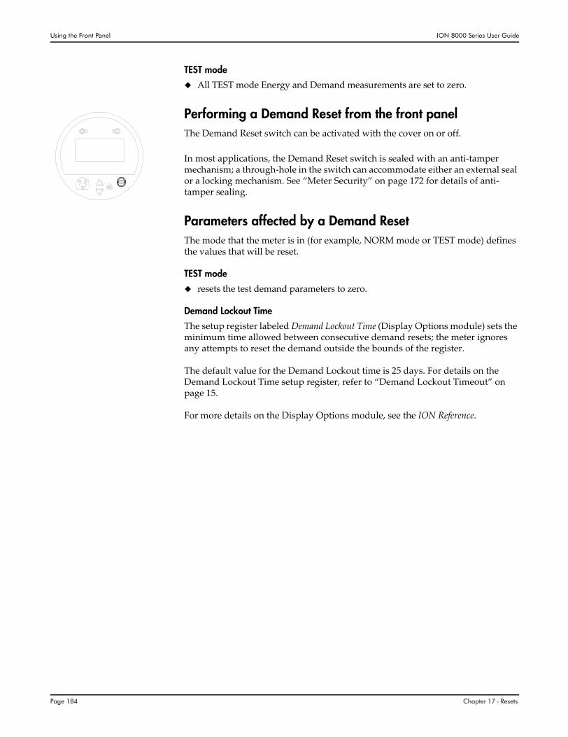
Using the Front Panel ION 8000 Series User Guide
Page 184 Chapter 17 - Resets
TEST mode
All TEST mode Energy and Demand measurements are set to zero.
Performing a Demand Reset from the front panel The Demand Reset switch can be activated with the cover on or off.
In most applications, the Demand Reset switch is sealed with an anti-tamper mechanism; a through-hole in the switch can accommodate either an external seal or a locking mechanism. See “Meter Security” on page 172 for details of anti-tamper sealing.
Parameters affected by a Demand ResetThe mode that the meter is in (for example, NORM mode or TEST mode) defines the values that will be reset.
TEST mode
resets the test demand parameters to zero.
Demand Lockout Time
The setup register labeled Demand Lockout Time (Display Options module) sets the minimum time allowed between consecutive demand resets; the meter ignores any attempts to reset the demand outside the bounds of the register.
The default value for the Demand Lockout time is 25 days. For details on the Demand Lockout Time setup register, refer to “Demand Lockout Timeout” on page 15.
For more details on the Display Options module, see the ION Reference.
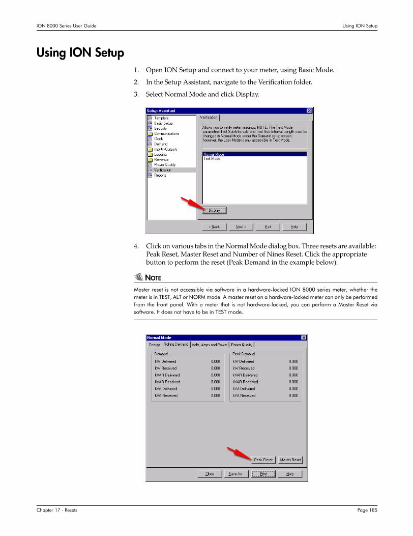
ION 8000 Series User Guide Using ION Setup
Chapter 17 - Resets Page 185
Using ION Setup1. Open ION Setup and connect to your meter, using Basic Mode.
2. In the Setup Assistant, navigate to the Verification folder.
3. Select Normal Mode and click Display.
4. Click on various tabs in the Normal Mode dialog box. Three resets are available: Peak Reset, Master Reset and Number of Nines Reset. Click the appropriate button to perform the reset (Peak Demand in the example below).
NOTE
Master reset is not accessible via software in a hardware-locked ION 8000 series meter, whether themeter is in TEST, ALT or NORM mode. A master reset on a hardware-locked meter can only be performedfrom the front panel. With a meter that is not hardware-locked, you can perform a Master Reset viasoftware. It does not have to be in TEST mode.
Using Vista ION 8000 Series User Guide
Page 186 Chapter 17 - Resets
A dialog box informs you when the reset is complete.
Using VistaOpen your meter in Vista. You can perform several resets from within Vista:
Performing a Peak Demand Reset or Master Reset
NOTE
Master reset is not accessible via software in a hardware-locked ION 8000 series meter, whether themeter is in TEST, ALT or NORM mode. A master reset on a hardware-locked meter can only be performedfrom the front panel. With a meter that is not hardware-locked, you can perform a Master Reset viasoftware. It does not have to be in TEST mode.
1. Click the System & Logs tab and click the Setup & Controls object.
2. Click the appropriate reset button to perform the reset.
Performing a Min/Max Reset
1. Click the Volts & Amps tab and click the Long-term Min/Max Measurements object.
2. Click the Min/Max reset button to perform the reset.
Performing a Sag/Swell, Availability or Harmonics Min/Max Reset
1. Click the Power Quality tab and click the Power Quality Controls object.
2. Click the appropriate reset button to perform the reset.
Page 187
18 AlertingION alerts can send an email or contact a modem, fax, pager, or software in the event of a user-specified condition. These conditions can be changes in relays or power quality problems including surges, sags, swells and outages.
This chapter explains how to configure your meter network for alerting.
In this chapter
Alerting . . . . . . . . . . . . . . . . . . . . . . . . . . . . . . . . . . . . . . . . . . . . . . . . . 188Alerting ION Software via the Alarm Server . . . . . . . . . . . . . . . . . . . . . . . . . . . . 188
Remote Site Event Notification ......................................................................... 189Alerting via an Alphanumeric Pager . . . . . . . . . . . . . . . . . . . . . . . . . . . . . . . . . . . 189Alerting via a Numeric Pager . . . . . . . . . . . . . . . . . . . . . . . . . . . . . . . . . . . . . . . . . 190Alerting via Email . . . . . . . . . . . . . . . . . . . . . . . . . . . . . . . . . . . . . . . . . . . . . . . . . . . 191
Alerting ION 8000 Series User Guide
Page 188 Chapter 18 - Alerting
AlertingThe meter’s Alert module sends an alert whenever its Trigger input is pulsed. You can connect this input to any module that produces a pulse output. You can use modules that monitor alarm conditions such as changes in relay status and power quality problems. For example, you can connect the Trigger input to the output of a Setpoint module, thereby allowing the Alert module to send an alert when the setpoint condition is reached.
The Alert module delivers these types of alerts:
Numeric Pager
Alphanumeric Pager
PEGASYS (for alerts to PEGASYS software)
ION Alert (for alerts to ION Enterprise software)
ASCII
Selection between modes is made with the Alert module Alert Type setup register.
The Alert module requires access to either a modem (a dedicated modem or a modem handling a loop of meters) or Ethernet (for the Alert module email capabilities).
Your meter has no pre-configured Alert framework. For detailed information about alerting, including how to build a framework to send alerts, refer to the Alert module description in the ION Reference.
Alerting ION Software via the Alarm ServerNOTE
For detailed information about sending alerts to ION Enterprise software via the Alarm Server, refer tothe ION Enterprise online help.
The Alarm Server can run on any ION software Primary or Secondary server. The server computer should have a dedicated phone line and modem. Modems at remote sites are programmed to dial the server's phone number when a priority event occurs. The Alarm Server monitors the phone line and waits for the remote sites to annunciate events. The most common use of the Alarm Server is to handle Remote Site Event Notification.
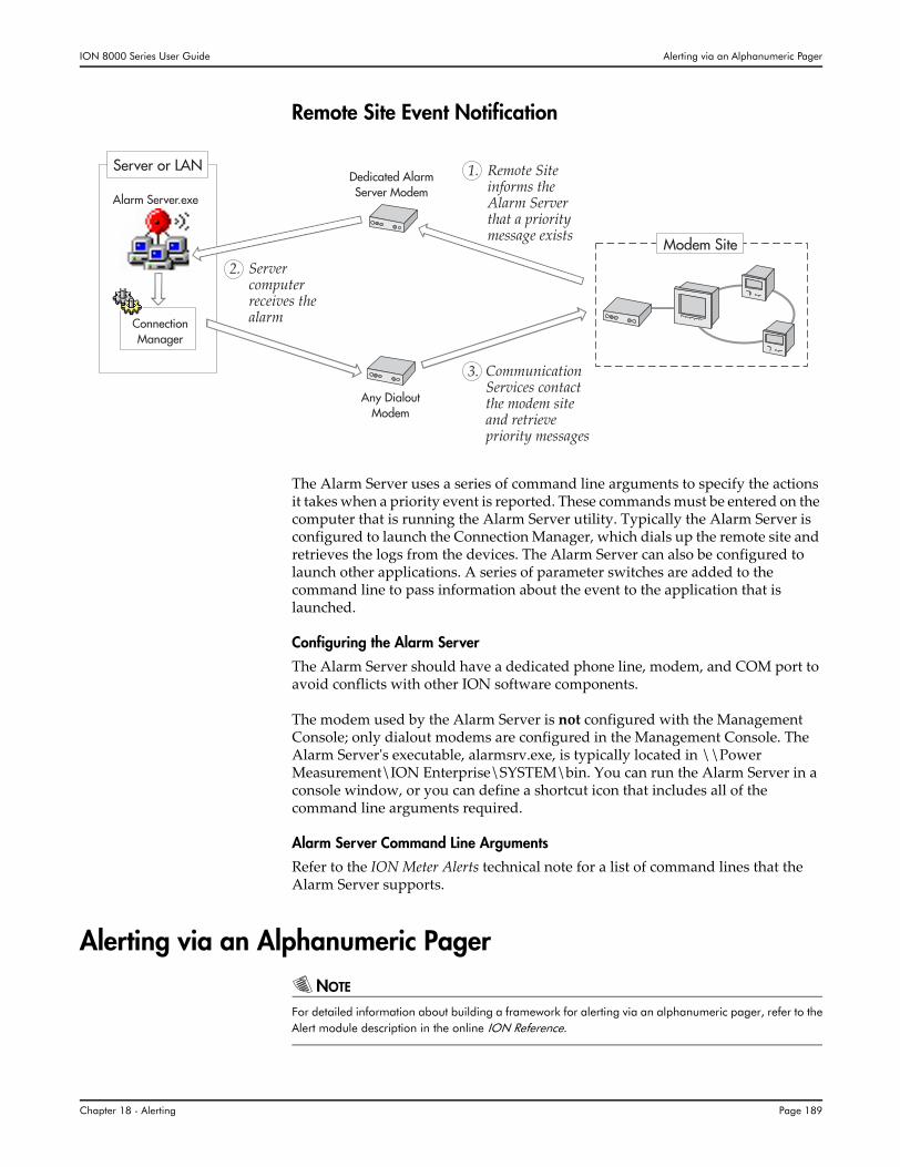
ION 8000 Series User Guide Alerting via an Alphanumeric Pager
Chapter 18 - Alerting Page 189
Remote Site Event Notification
The Alarm Server uses a series of command line arguments to specify the actions it takes when a priority event is reported. These commands must be entered on the computer that is running the Alarm Server utility. Typically the Alarm Server is configured to launch the Connection Manager, which dials up the remote site and retrieves the logs from the devices. The Alarm Server can also be configured to launch other applications. A series of parameter switches are added to the command line to pass information about the event to the application that is launched.
Configuring the Alarm Server
The Alarm Server should have a dedicated phone line, modem, and COM port to avoid conflicts with other ION software components.
The modem used by the Alarm Server is not configured with the Management Console; only dialout modems are configured in the Management Console. The Alarm Server's executable, alarmsrv.exe, is typically located in \\Power Measurement\ION Enterprise\SYSTEM\bin. You can run the Alarm Server in a console window, or you can define a shortcut icon that includes all of the command line arguments required.
Alarm Server Command Line Arguments
Refer to the ION Meter Alerts technical note for a list of command lines that the Alarm Server supports.
Alerting via an Alphanumeric PagerNOTE
For detailed information about building a framework for alerting via an alphanumeric pager, refer to theAlert module description in the online ION Reference.
Dedicated AlarmServer Modem
Modem Site
Any DialoutModem
ConnectionManager
Alarm Server.exe
Server or LAN
CommunicationServices contactthe modem siteand retrievepriority messages
3.
Remote Siteinforms theAlarm Serverthat a prioritymessage exists
1.
Servercomputerreceives thealarm
2.
Alerting via a Numeric Pager ION 8000 Series User Guide
Page 190 Chapter 18 - Alerting
If an alphanumeric pager is specified as the destination address in the Alert module, then an alphanumeric paging service receives a message from the ION meter.
Once the modem at the paging service is contacted, the ION meter transmits the following information:
Pager identification number
Local time (year, month, date, hours, minutes, seconds)
Remote site identification
Priority of the alarm
Alert message, with text strings and realtime measured values
To include a module’s Source input in the message, reference the message string by using the form %Vn, where n is the Source input number. In the following Message register setting, the kWtot value is %V1. The string includes Source input 1 which would be the kWtot register from the Power Meter module.
The destination register contains your modem access number for the paging service provider and is what is dialed out first. The Pager Num register is the pager access number that is provided by your paging company.
Alerting via a Numeric PagerNOTE
For detailed information about building a framework for alerting via a numeric pager, refer to the Alertmodule description in the online ION Reference.
If a numeric pager is specified as the destination address in the Alert module, then a numeric paging service receives a message from the ION meter. Due to the inherent limitations in numeric paging, the ION meter can only send a string of digits to the paging service. The Alert module then waits a specified time, determined by the number of commas inserted after the phone number in the Pager Num setup register. Finally, the Alert module dials the message digital string.
There are two important factors to consider when setting up the Alert module for numeric paging. First, be sure to specify a string of digits that is meaningful to you, such as a coded message. Second, be aware that there is no way to ensure that a message has been successfully transmitted; there may be a busy signal or an answering machine may take the call. The number of commas you add to your dial string is an estimate of how long the modem at the remote site waits before it transmits numbers.
NOTE
In the following destination-setting example: 1-250-555-777,,,,,999#, the pager number is 1-250-555-777 and the message string that displays on the pager is 999. You may need to insert 9,,, before thedestination number if the line you are using is not a direct line. In this case the destination number is 9,,1-250-555-666,,999#
ION 8000 Series User Guide Alerting via Email
Chapter 18 - Alerting Page 191
Alerting via Email NOTE
For detailed information about setting up your network and building a framework for meter email(MeterM@il) alerts, refer to the technical note ION MeterM@il.
If email is specified as the destination address in the Alert module then an email message is sent to any address you specify. You can only set one email address per Alert module. If you want to send an alert to more than one email address you need to create a group — be sure your email server is configured to send email to groups via SMTP (Simple Message Transport Protocol).
Follow the steps below to send email alerts from your meter. Note that your meter must support emailing (with a correctly configured SMTP server):
1. Create an Alert module.
2. Configure these Alert module setup registers as indicated:
Message – type in the text of the alert to be emailed.
Destination – type in the destination email address.
Type – select Email.
Com Port – select Ethernet.
Location – type in a custom string; this is optional, and appears in the email.
Email From – type in an address that you want the email to appear from. This may be required as some SMTP servers only accept emails from valid addresses.
3. Create an ION module that will produce a pulse on its Trigger output when the exceptional event occurs (for example, a Setpoint module pulses its Trigger output when the setpoint condition is reached).
4. Link the Alert module’s Trigger input to the Trigger output of the module created in step 3.
Send and save. When the Trigger input is pulsed, the Alert module establishes communications with the SMTP mail server, and emails the alert message.

Page 193
19 SetpointsThis chapter provides instructions for configuring meter setpoints.
In this chapter
Introduction . . . . . . . . . . . . . . . . . . . . . . . . . . . . . . . . . . . . . . . . . . . . . . 194
Configuring Setpoints . . . . . . . . . . . . . . . . . . . . . . . . . . . . . . . . . . . . . . . 194Using the Front Panel ......................................................................................... 194Using ION Setup ................................................................................................. 194Using Vista ........................................................................................................... 194
Relative Setpoint Module Settings . . . . . . . . . . . . . . . . . . . . . . . . . . . . . . . . . . . . . 195Fine Tuning Over Condition Monitoring ........................................................ 195
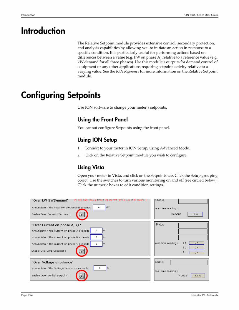
Introduction ION 8000 Series User Guide
Page 194 Chapter 19 - Setpoints
IntroductionThe Relative Setpoint module provides extensive control, secondary protection, and analysis capabilities by allowing you to initiate an action in response to a specific condition. It is particularly useful for performing actions based on differences between a value (e.g. kW on phase A) relative to a reference value (e.g. kW demand for all three phases). Use this module’s outputs for demand control of equipment or any other applications requiring setpoint activity relative to a varying value. See the ION Reference for more information on the Relative Setpoint module.
Configuring SetpointsUse ION software to change your meter’s setpoints.
Using the Front PanelYou cannot configure Setpoints using the front panel.
Using ION Setup1. Connect to your meter in ION Setup, using Advanced Mode.
2. Click on the Relative Setpoint module you wish to configure.
Using VistaOpen your meter in Vista, and click on the Setpoints tab. Click the Setup grouping object. Use the switches to turn various monitoring on and off (see circled below). Click the numeric boxes to edit condition settings.
ION 8000 Series User Guide Relative Setpoint Module Settings
Chapter 19 - Setpoints Page 195
Relative Setpoint Module SettingsThe Relative Setpoint modules monitor the following for “over” conditions: phase current, kW demand, and voltage unbalance.
NOTE
There is usually no need to change any of the Relative Setpoint modules’ setup registers for normaloperation of the meter.
See the ION Reference for more information on the Relative Setpoint module.
Fine Tuning Over Condition MonitoringIf you want to fine-tune over condition monitoring, the only setup registers you should change are SusUntlON and SusUntlOFF.
SusUntlON determines how long the modules wait after an over condition is detected before reporting it. This gives the monitored value a short period to correct itself before the event is registered with the module so that very brief over conditions are ignored. Similarly, SusUntlOFF is the amount of time a normal value must be present before the module considers normal operation to be restored. Both SusUntlON and SusUntlOFF values are entered in seconds (the default value for both is 30 seconds).
Module Label Description
Relative Setpoint 1 Over KW sd When active, this annunciates when the total kW SWDemand exceeds a specified amount.
Relative Setpoint 2 Over I a When active, this annunciates when the current on phase A exceeds a specified amount.
Relative Setpoint 3 Over I b When active, this annunciates when the current on phase B exceeds a specified amount.
Relative Setpoint 4 Over I c When active, this annunciates when the current on phase C exceeds a specified amount.
Relative Setpoint 5 Over V unbal When active, this annunciates if the voltage unbalance exceeds a specified percentage.
Relative Setpoint 6 Over I 4 When active, this annunciates when I 4 exceeds a specified amount.
Relative Setpoint 7 Over I 5 When active, this annunciates when I 5 exceeds a specified amount.

Page 197
20 Power AvailabilityThe ION 8400 and ION 8500 meters come pre-configured with a power availability framework that provides reliability measurements using “number of nines” calculations.
NOTE
While the Availability Framework is pre-configured, the operation of this framework requires the correctconfiguration of the Sag/Swell module according to your meter’s power supply and operating ranges.See “Sag/Swell Module Configuration” on page 200. See also the ION Reference for detaileddescriptions of this module.
In this chapter
Introduction . . . . . . . . . . . . . . . . . . . . . . . . . . . . . . . . . . . . . . . . . . . . . . 198
Availability on the Meter Front Panel . . . . . . . . . . . . . . . . . . . . . . . . . . . . 199Sample Availability Framework Behaviors (ION 8400, ION 8500) . . . . . . . . . . 199
Assumptions ........................................................................................................ 199Sag/Swell Module Configuration . . . . . . . . . . . . . . . . . . . . . . . . . . . . . . . . . . . . . . 200Resetting and Pausing Power Availability . . . . . . . . . . . . . . . . . . . . . . . . . . . . . . . 200
Using the front panel .......................................................................................... 200Using ION Setup ................................................................................................. 200Using Vista ........................................................................................................... 201Pausing Availability ............................................................................................ 202
Detailed Behavior . . . . . . . . . . . . . . . . . . . . . . . . . . . . . . . . . . . . . . . . . . 203Terminology ......................................................................................................... 204
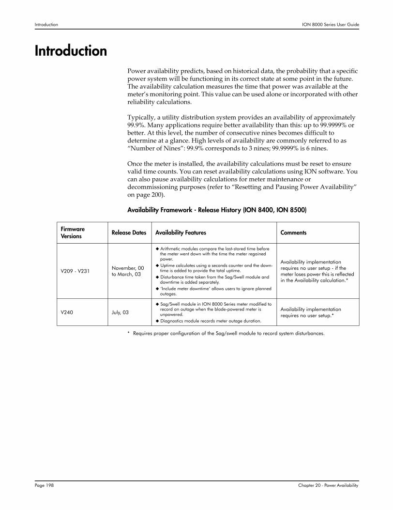
Introduction ION 8000 Series User Guide
Page 198 Chapter 20 - Power Availability
IntroductionPower availability predicts, based on historical data, the probability that a specific power system will be functioning in its correct state at some point in the future. The availability calculation measures the time that power was available at the meter’s monitoring point. This value can be used alone or incorporated with other reliability calculations.
Typically, a utility distribution system provides an availability of approximately 99.9%. Many applications require better availability than this: up to 99.9999% or better. At this level, the number of consecutive nines becomes difficult to determine at a glance. High levels of availability are commonly referred to as “Number of Nines”: 99.9% corresponds to 3 nines; 99.9999% is 6 nines.
Once the meter is installed, the availability calculations must be reset to ensure valid time counts. You can reset availability calculations using ION software. You can also pause availability calculations for meter maintenance or decommissioning purposes (refer to “Resetting and Pausing Power Availability” on page 200).
Availability Framework - Release History (ION 8400, ION 8500)
* Requires proper configuration of the Sag/swell module to record system disturbances.
Firmware Versions Release Dates Availability Features Comments
V209 - V231 November, 00 to March, 03
Arithmetic modules compare the last-stored time before the meter went down with the time the meter regained power. Uptime calculates using a seconds counter and the down-time is added to provide the total uptime.Disturbance time taken from the Sag/Swell module and downtime is added separately.‘Include meter downtime’ allows users to ignore planned outages.
Availability implementation requires no user setup - if the meter loses power this is reflected in the Availability calculation.*
V240 July, 03
Sag/Swell module in ION 8000 Series meter modified to record an outage when the blade-powered meter is unpowered.Diagnostics module records meter outage duration.
Availability implementation requires no user setup.*
ION 8000 Series User Guide Availability on the Meter Front Panel
Chapter 20 - Power Availability Page 199
Availability on the Meter Front PanelThe following power availability values display on the meter’s front panel, and are viewable in the Vista™ component of ION Enterprise™ or ION Setup™ software:
Number of Nines: the number of consecutive nines that appear in the most-significant digits of the availability value (e.g. “10” on the front panel indicates 10 nines: 99.99999999).
Availability-ppm: the fraction of time that the power is available, in parts per million (ppm).
Evaluation Time (days): the number of days that have elapsed since the calculation was last reset. This gives an indication of the time interval over which the availability calculation is made.
The availability framework is found at this location within Designer: Advanced Setup\Power Quality Framework\Power Availability Framework.
Sample Availability Framework Behaviors (ION 8400, ION 8500)Scenario 1: blade powered meter + power system outage
The Sag/Swell total disturbance time includes the outage. The meter downtime from the diagnostics module is added to the meter uptime to account for the total time of observation.
Scenario 2: blade powered meter + meter decommissioned
The Sag/Swell module logs the downtime as disturbance time. When the meter powers back up, the meter downtime from the diagnostics module is added to the meter uptime.
Scenario 3: auxiliary powered meter + power system outage
The Sag/Swell total disturbance time includes the outage. The meter never loses power, which means that there is no meter downtime and the meter uptime is equivalent to the total time of observation.
Scenario 4: auxiliary powered meter + meter decommissioned
The Sag/Swell module does not log a disturbance time. When the meter powers back up, the meter downtime from the diagnostics module is added to the meter uptime.
AssumptionsThe above scenarios assume that:
1. The auxiliary powered meter assumed the power system was within specs during a meter down time if it didn't detect a disturbance prior to powering down.
2. The Sag/Swell module is configured correctly to monitor voltage disturbances.
3. The Sag limit is set above the voltage level at which the meter starts powering down.
Sag/Swell Module Configuration ION 8000 Series User Guide
Page 200 Chapter 20 - Power Availability
4. An auxiliary powered meter is used for applications that require a highly accurate measurement of power system downtime.
Sag/Swell Module ConfigurationYour meter’s power availability framework requires that the Sag/Swell module be configured to the limits of your meter’s power supply specification.
For the most current specifications, see the ION 8000 Series Installation Guide.
See the ION Reference for detailed information on the operation of the Sag/Swell module.
The ANSI C84.1 1989 standard recommends a Swell limit of 106% for Range B voltage levels, as well as a Sag limit of 88% for load voltages and 92% for the service entrance.
Resetting and Pausing Power AvailabilityThe power availability framework in the ION 8400 and ION 8500 meters allows the user to pause or reset its operation. The framework can be paused and reset with ION software.
Using the front panelYou cannot reset availability using the meter’s front panel.
Using ION SetupWith ION Setup software, you can reset availability calculations by clicking on the button labeled “# of 9s Reset” in the Verification > Normal Mode > Power Quality tab.
1. Launch ION Setup software and double-click the Setup Assistant.
2. Click on the Verification setup screen, and from that screen, double-click Normal Mode.
3. In the Normal Mode screen, click the Power Quality tab.
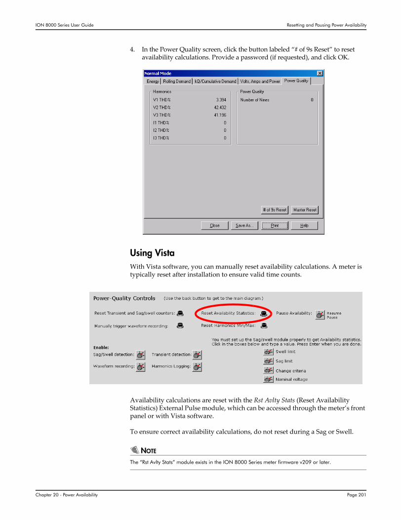
ION 8000 Series User Guide Resetting and Pausing Power Availability
Chapter 20 - Power Availability Page 201
4. In the Power Quality screen, click the button labeled “# of 9s Reset” to reset availability calculations. Provide a password (if requested), and click OK.
Using VistaWith Vista software, you can manually reset availability calculations. A meter is typically reset after installation to ensure valid time counts.
Availability calculations are reset with the Rst Avlty Stats (Reset Availability Statistics) External Pulse module, which can be accessed through the meter’s front panel or with Vista software.
To ensure correct availability calculations, do not reset during a Sag or Swell.
NOTE
The “Rst Avlty Stats” module exists in the ION 8000 Series meter firmware v209 or later.
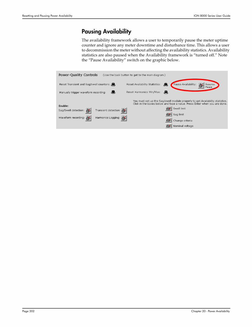
Resetting and Pausing Power Availability ION 8000 Series User Guide
Page 202 Chapter 20 - Power Availability
Pausing AvailabilityThe availability framework allows a user to temporarily pause the meter uptime counter and ignore any meter downtime and disturbance time. This allows a user to decommission the meter without affecting the availability statistics. Availability statistics are also paused when the Availability framework is “turned off.” Note the “Pause Availability” switch on the graphic below.
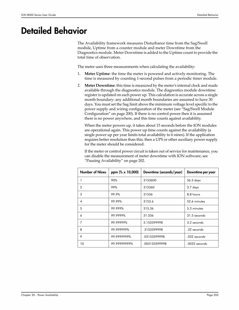
ION 8000 Series User Guide Detailed Behavior
Chapter 20 - Power Availability Page 203
Detailed BehaviorThe Availability framework measures Disturbance time from the Sag/Swell module, Uptime from a counter module and meter Downtime from the Diagnostics module. Meter Downtime is added to the Uptime count to provide the total time of observation.
The meter uses three measurements when calculating the availability:
1. Meter Uptime: the time the meter is powered and actively monitoring. The time is measured by counting 1-second pulses from a periodic timer module.
2. Meter Downtime: this time is measured by the meter’s internal clock and made available through the diagnostics module. The diagnostics module downtime register is updated on each power up. This calculation is accurate across a single month boundary: any additional month boundaries are assumed to have 30 days. You must set the Sag limit above the minimum voltage level specific to the power supply and wiring configuration of the meter (see “Sag/Swell Module Configuration” on page 200). If there is no control power then it is assumed there is no power anywhere, and this time counts against availability.
When the meter powers up, it takes about 15 seconds before the ION modules are operational again. This power up time counts against the availability (a single power up per year limits total availability to 6 nines). If the application requires better resolution than this, then a UPS or other auxiliary power supply for the meter should be considered.
If the meter or control power circuit is taken out of service for maintenance, you can disable the measurement of meter downtime with ION software; see “Pausing Availability” on page 202.
Number of Nines ppm (% x 10,000) Downtime (seconds/year) Downtime per year
1 90% 3153600 36.5 days
2 99% 315360 3.7 days
3 99.9% 31536 8.8 hours
4 99.99% 3153.6 52.6 minutes
5 99.999% 315.36 5.3 minutes
6 99.9999% 31.536 31.5 seconds
7 99.99999% 3.153599998 3.2 seconds
8 99.999999% .3153599998 .32 seconds
9 99.9999999% .03153599998 .032 seconds
10 99.99999999% .003153599998 .0032 seconds
Detailed Behavior ION 8000 Series User Guide
Page 204 Chapter 20 - Power Availability
3. Voltage Disturbance Duration: the total number of seconds that the voltage was outside the envelope determined by the Sag/Swell module. If several sags or swells occur during one second, only the last one counts toward the total. The Sag/Swell module settings may be used to control the voltage tolerance. If the Sag/Swell module is not enabled, no voltage disturbances are counted.
TerminologyBlade-powered meter: the power to run the meter is derived from the Voltage input terminals that are connected to the monitored system. The meter loses power if the monitored system is down. Specific to ION 8000 Series only.
Auxiliary-powered meter: The power to run the meter is derived from an independent power source. The meter remains powered when the monitored system is down. Specific to ION 8000 Series only.
Meter uptime: the time the meter is powered and actively monitoring. The time is measured by counting 1-second pulses from a periodic timer module.
Meter downtime: the time the meter is not powered. This time is measured by the meter’s internal clock and made available through the diagnostics module. The diagnostics module downtime register is reset at the beginning of each outage.
Availability: the probability of finding a system in the operating state at some time into the future. Availability is calculated as:
Unavailability: calculated in the framework and then converted to number of nines, and Availability in percent and parts per million (ppm):
Time the power system is operating within specificationsTotal time of operation*
Availability =
* Where total time of observation = uptime + meter downtime
Meter uptime - disturbance timeMeter uptime + meter downtime
=
Time the power system is operating outside specificationsTotal time of operation*
Unavailability =
Disturbance timeMeter uptime + meter downtime
=
* Where total time of observation = uptime + meter downtime
Page 205
21 ReportsThis chapter provides instructions for viewing various meter reports and logs.
In this chapter
Introduction . . . . . . . . . . . . . . . . . . . . . . . . . . . . . . . . . . . . . . . . . . . . . . 206
Viewing Meter Logs . . . . . . . . . . . . . . . . . . . . . . . . . . . . . . . . . . . . . . . . 206Using the Front Panel ......................................................................................... 206Using ION Setup ................................................................................................. 206Using Vista ........................................................................................................... 208
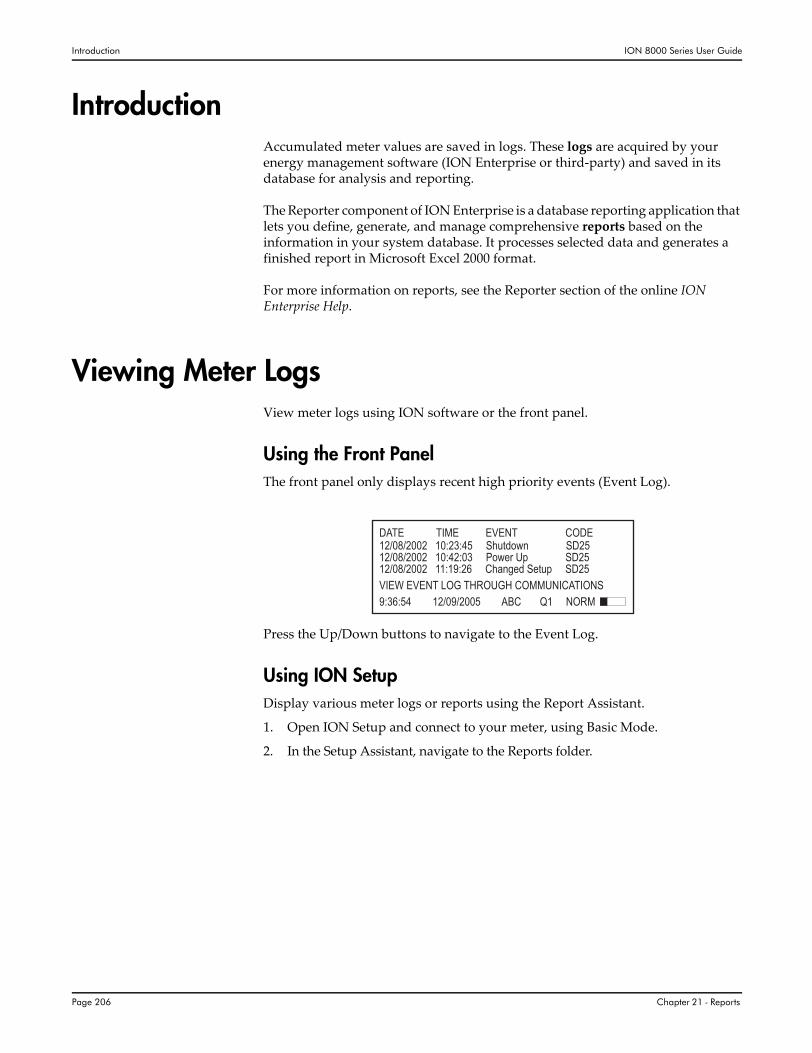
Introduction ION 8000 Series User Guide
Page 206 Chapter 21 - Reports
IntroductionAccumulated meter values are saved in logs. These logs are acquired by your energy management software (ION Enterprise or third-party) and saved in its database for analysis and reporting.
The Reporter component of ION Enterprise is a database reporting application that lets you define, generate, and manage comprehensive reports based on the information in your system database. It processes selected data and generates a finished report in Microsoft Excel 2000 format.
For more information on reports, see the Reporter section of the online ION Enterprise Help.
Viewing Meter LogsView meter logs using ION software or the front panel.
Using the Front PanelThe front panel only displays recent high priority events (Event Log).
Press the Up/Down buttons to navigate to the Event Log.
Using ION SetupDisplay various meter logs or reports using the Report Assistant.
1. Open ION Setup and connect to your meter, using Basic Mode.
2. In the Setup Assistant, navigate to the Reports folder.
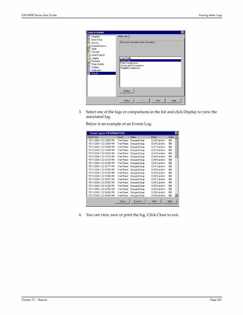
ION 8000 Series User Guide Viewing Meter Logs
Chapter 21 - Reports Page 207
3. Select one of the logs or comparisons in the list and click Display to view the associated log.
Below is an example of an Events Log.
4. You can view, save or print the log. Click Close to exit.
Viewing Meter Logs ION 8000 Series User Guide
Page 208 Chapter 21 - Reports
Using VistaOpen your meter in Vista and click on the various tabs available. Click a grouping object to view the associated logs. The following logs are available in Vista:
Volts/Amps tab:
Meter EventsVoltageCurrentPowerFrequency/PF
Revenue tab:
Revenue Data
Power Quality tab:
Harmonics TrendingTransient & Sag/Swell Statistics CBEMAWaveforms/Sequence of Events
Page 209
22 Theory of OperationUsed to monitor electric power networks, service entrances and substations, the ION 8000 series is the most advanced energy meter available today. It has expanded power quality analysis and compliance reporting to quickly characterize power. Enhancements include transient capture, an increased sampling rate, additional harmonics depth, and more memory.
The meter addresses deregulation requirements with the tools to manage complex energy supply contracts that include commitments to power quality.
In this chapter
Meter Components . . . . . . . . . . . . . . . . . . . . . . . . . . . . . . . . . . . . . . . . . 210
Major Components of the PCB Boards . . . . . . . . . . . . . . . . . . . . . . . . . . . 211CPU Board ............................................................................................................ 211Analog Board ....................................................................................................... 212Communications Board ...................................................................................... 213Power Supply Filter Board ................................................................................. 214Power Supply Switcher Board ........................................................................... 215Display Board ...................................................................................................... 216
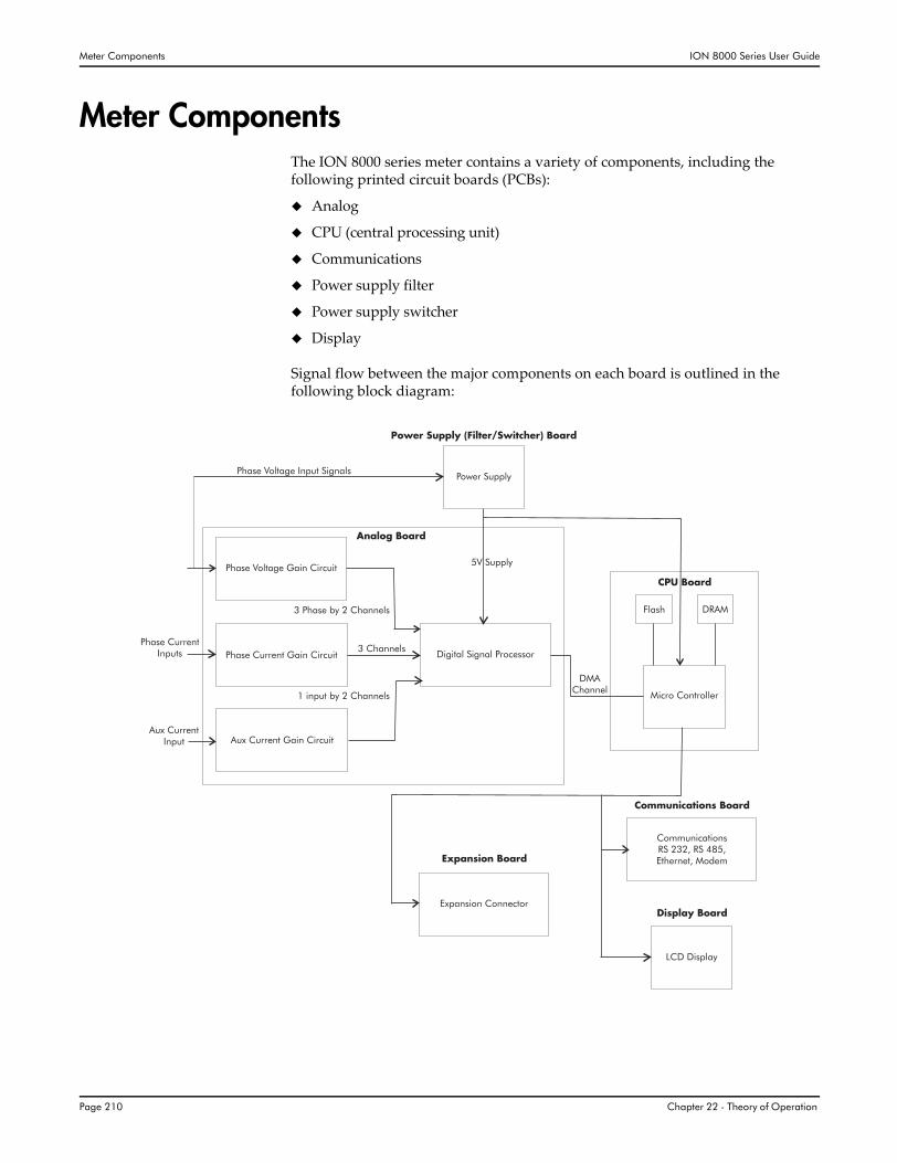
Meter Components ION 8000 Series User Guide
Page 210 Chapter 22 - Theory of Operation
Meter ComponentsThe ION 8000 series meter contains a variety of components, including the following printed circuit boards (PCBs):
Analog
CPU (central processing unit)
Communications
Power supply filter
Power supply switcher
Display
Signal flow between the major components on each board is outlined in the following block diagram:
Expansion Connector
Expansion Board
LCD Display
Display Board
CommunicationsRS 232, RS 485,Ethernet, Modem
Communications Board
Analog Board
Power Supply
Power Supply (Filter/Switcher) Board
Phase Voltage Gain Circuit
Phase Current Gain Circuit
Aux Current Gain Circuit
Digital Signal Processor
Micro Controller
CPU Board
DRAMFlash
Phase Voltage Input Signals
Phase CurrentInputs
Aux CurrentInput
5V Supply
3 Phase by 2 Channels
3 Channels
1 input by 2 Channels
DMAChannel
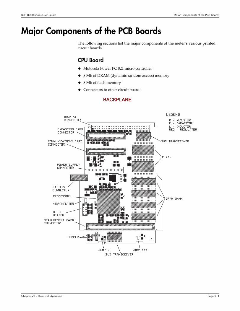
ION 8000 Series User Guide Major Components of the PCB Boards
Chapter 22 - Theory of Operation Page 211
Major Components of the PCB BoardsThe following sections list the major components of the meter’s various printed circuit boards.
CPU BoardMotorola Power PC 821 micro controller
8 Mb of DRAM (dynamic random access) memory
8 Mb of flash memory
Connectors to other circuit boards
BACKPLANEBACKPLANE
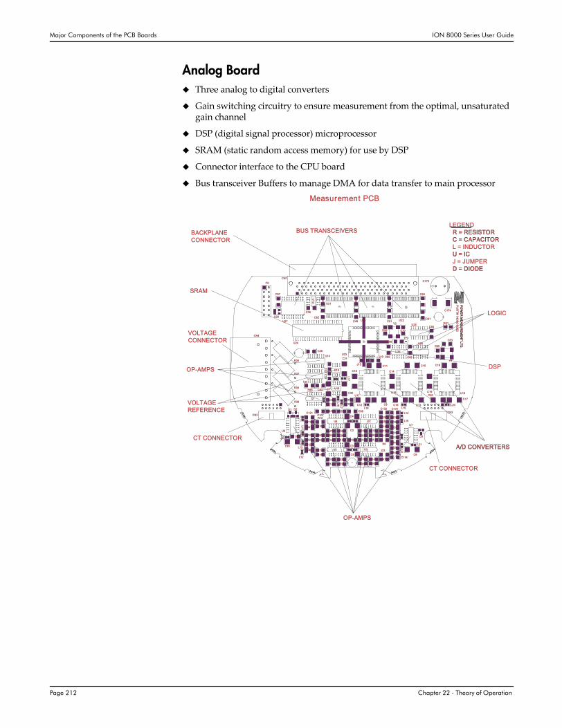
Major Components of the PCB Boards ION 8000 Series User Guide
Page 212 Chapter 22 - Theory of Operation
Analog BoardThree analog to digital converters
Gain switching circuitry to ensure measurement from the optimal, unsaturated gain channel
DSP (digital signal processor) microprocessor
SRAM (static random access memory) for use by DSP
Connector interface to the CPU board
Bus transceiver Buffers to manage DMA for data transfer to main processor
LEGEND
R = RESISTORR = RESISTOR
C = CAPACITORC = CAPACITOR
L = INDUCTOR
U = ICU = IC
J = JUMPER
D = DIODED = DIODE
DSP
OP-AMPS
OP-AMPS
VOLTAGE
REFERENCE
VOLTAGE
CONNECTOR
CT CONNECTOR
CT CONNECTOR
A/D CONVERTERSA/D CONVERTERS
LOGIC
BUS TRANSCEIVERSBACKPLANE
CONNECTOR
SRAM
C81
L24 C177
U9
D1 D2
L10
C119
C121
U1
C83
U6
R86
L1
C21
C71
C141
J7
J9
J10
J12
C3
L6 L4
C5
C135
C95
J4
J6
C111
U2
C132
R25
R28 C130 L15
L14
C129
C131
R52
C117
C118
L8
L9
L21
C6
U7
D3
C113
C114
R5
R7C116
C115
J20
R46
U3
C144
C143C2
L2L5
C98C137
C78
C77
C30
L3
U15
C3
2
C1 U16
L16
L17
C31
C3
3
U14
C36
C62
U1
3
C6
3
C35
C57
U29
U27
R36
CN4
R37
R38
R39
CN2 C107R12
R10R47
C120 R50
C109
R17
R15
R48
C124
C126
L13
L12
L11
C142
U4
C4
C136
C97
C138 C103
C93
C134
C140
C105
J23
C139
C101
U5
L18
C12 C9
U17
C10
J15
U23
C49
C5
0
U21
U20
C5
2
C51 U22
Y2
R99 C70
R108
TP3
C68
U28
C15
C19U19
C20
CN3
L20
C17
C18
Y1
R95
C53
C55U25
C61
C60
C174
C175
DS1
U26
C69J19
C11
C14
U18
C16L19
C13L7
U24
CN1
P2
PO
WE
RM
EA
SU
RE
ME
NT
LT
D.
PO
WE
RM
EA
SU
RE
ME
NT
LT
D.
PA
RT
#1
40
00-0
052
Measurement PCB
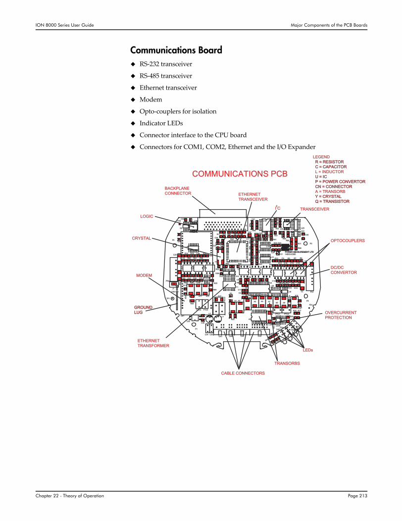
ION 8000 Series User Guide Major Components of the PCB Boards
Chapter 22 - Theory of Operation Page 213
Communications BoardRS-232 transceiver
RS-485 transceiver
Ethernet transceiver
Modem
Opto-couplers for isolation
Indicator LEDs
Connector interface to the CPU board
Connectors for COM1, COM2, Ethernet and the I/O Expander
14000-0060
POWER MEASUREMENT LTDPOWER MEASUREMENT LTD
R71
R66
R60
U25U24
C40
U21
T1
TP1
CN2
C2
0
C23 C21 C22
C19 R20
U1
5
U12
A12A11
A13
R2
9
R25
PTC3 PTC4
PT
C5
PT
C6
A17
R2
A2
A6
A3 A4 A7A5 A9
A10
U8
U9
C5
C12R6
C1
0
R2
7
R9
C8
C6
C11
C9
U1
R43
R4
2
R3
9
R3
8R
35
R3
7R
36
R52
R56
R50
C3
0
R4
0
DS3 R2
1
R41
U16
C24
R28 R24
Q1
R53
R5
7
R51
U20
R6
5
R4
8
R49
R58
C41
U19
R3R61R59R12R11
C28
C29
Y1
C27U7
C26
R30
U1
4
R47R62
U1
3
R19R16C25
PS2
C15
R23 R26
R55
R31
R32
R46 R44
A15 A14
DS6
U2
R4
R10
R13
C4
U5
C18
R5
C14
R7
C13
R8
U6
R15
C3
R18
C17R14
U1
0
U1
1
C7
U4 C16
C2
FD1
R17R33
DS1
DS2
DS4
DS5
R64
R45
C3
3
CN3
A8
R63
PTC1 PTC2
CN4CN5CN1
C35C34
C36
L1
U22
L2
R22
A1
U17
R1
R54
P2
U18
Q2
C32
FD2
C31
R3
4
U3
C1
PS1
C37
C38
C39
J1
P1
P3
P4
P5
R67
R6
8
R69
R70
U23
U23A
2
COMMUNICATIONS PCB
CABLE CONNECTORS
ETHERNET
TRANSFORMER
GROUND
LUG
GROUND
LUG
MODEM
CRYSTAL
LOGIC
BACKPLANE
CONNECTOR
LEDs
OVERCURRENT
PROTECTION
TRANSORBS
DC/DC
CONVERTOR
OPTOCOUPLERS
TRANSCEIVER
ETHERNET
TRANSCEIVER
I C
LEGEND
R = RESISTORR = RESISTOR
C = CAPACITORC = CAPACITOR
L = INDUCTOR
U = ICU = IC
P = POWER CONVERTOR
CN = CONNECTOR
P = POWER CONVERTOR
CN = CONNECTOR
A = TRANSORB
Y = CRYSTAL
Q = TRANSISTOR
Y = CRYSTAL
Q = TRANSISTOR
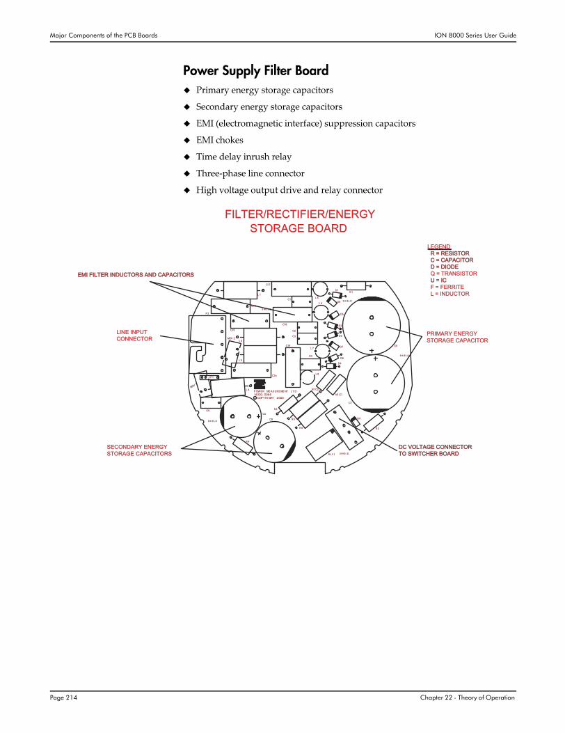
Major Components of the PCB Boards ION 8000 Series User Guide
Page 214 Chapter 22 - Theory of Operation
Power Supply Filter BoardPrimary energy storage capacitors
Secondary energy storage capacitors
EMI (electromagnetic interface) suppression capacitors
EMI chokes
Time delay inrush relay
Three-phase line connector
High voltage output drive and relay connector
S HI E L D
S HI E L D
S HI E L D
S HI E L D
P OW E R ME AS U R E ME NT L T D
14 000- 005 5
S HI E L D
COP Y R I GHT 2 000
MOV1
MOV 2
P 2
C1
C2
C3
C4
C5
C14
C15
C16
C17
C18
C19
D1
D2
D3
D4
D5
D6
D7
D8
L 1
L 2
L 3
L 4
L 5
L 6
L 7
L 8
NT C1
R 1
R 2
R 3
R 4
R 5
C6
C7
C8
C9
NT C2
D9
R 6
R L Y 1
J P 1
FILTER/RECTIFIER/ENERGY
EMI FILTER INDUCTORS AND CAPACITORSEMI FILTER INDUCTORS AND CAPACITORS
STORAGE BOARD
LINE INPUT
CONNECTOR
SECONDARY ENERGY
STORAGE CAPACITORS
DC VOLTAGE CONNECTORDC VOLTAGE CONNECTOR
TO SWITCHER BOARDTO SWITCHER BOARD
PRIMARY ENERGY
STORAGE CAPACITOR
LEGEND
R = RESISTORR = RESISTOR
C = CAPACITORC = CAPACITOR
D = DIODED = DIODE
Q = TRANSISTOR
U = ICU = IC
F = FERRITE
L = INDUCTOR
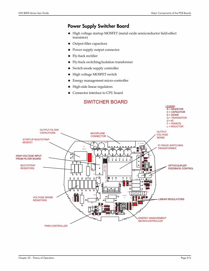
ION 8000 Series User Guide Major Components of the PCB Boards
Chapter 22 - Theory of Operation Page 215
Power Supply Switcher BoardHigh voltage startup MOSFET (metal oxide semiconductor field-effect transistor)
Output filter capacitors
Power supply output connector
Fly-back rectifier
Fly-back switching/isolation transformer
Switch-mode supply controller
High voltage MOSFET switch
Energy management micro-controller
High-side linear regulators
Connector interface to CPU board
S HI E L D
S HI E L D
S HI E L D
PO
WE
RM
EA
SU
RE
ME
NT
LT
D.
14
00
0-
00
54
CH
G.
LT
R
R 4 4
R 4 3
Q5
Q4
D1
C3 0
Q2
Q1
U 6 B
U 9
U 3
R 3 6
R 3 5
R 3 4
R 3 3
R 3 2
F 1
D8
C2 7
C2 5
C2 4
C2 3
C2 2
C2 0
C19
C18 C17
DS 1
L 1
U 5
C15
T 1
U8
U 7
U 6
U 4U 2
U 1
R 3 0
R 2 8 R 2 7
R 2 6
R 2 5
R 2 4
R 2 3
R 2 2
R 2 1
R 2 0
R 19
R 18
R 15
R 14
R 13
R 12
R 11
R 10
R 9
R 8
R 7
R 6
R 5R 4R 3
Q3
P 2
P 1D6
D5
D4
D3D2
CON1
C14
C13
C12
C11
C10
C9
C8C7
C6
C5
C4
C3
C2
C1
R 3 1
R 2
R 2 9
R 3 7
R3
8
C2 8
C2 9
R 4 0R 4 1R 4 2
D7
R 3 9
C2 1
GDS
1 2 3 4 5 6
13 12 11 10 9 8 7
BACKPLANE
CONNECTOR
SWITCHER BOARDSWITCHER BOARD
HIGH VOLTAGE INPUTHIGH VOLTAGE INPUT
FROM FILTER BOARDFROM FILTER BOARD
PWM CONTROLLER
ENERGY MANAGEMENT
MICROCONTROLLER
FLYBACK SWITCHING
TRANSFORMER
OUTPUT FILTER
CAPACITORS
STARTUP BOOTSTRAP
MOSFET
BOOTSTRAP
RESISTORS
VOLTAGE SENSE
RESISTORSLINEAR REGULATORSLINEAR REGULATORS
OPTOCOUPLER
FEEDBACK CONTROL
OPTOCOUPLER
FEEDBACK CONTROL
OUTPUT
VOLTAGE
SENSE
LEGEND
R = RESISTORR = RESISTOR
C = CAPACITORC = CAPACITOR
D = DIODED = DIODE
Q = TRANSISTOR
U = ICU = IC
F = FERRITE
L = INDUCTOR
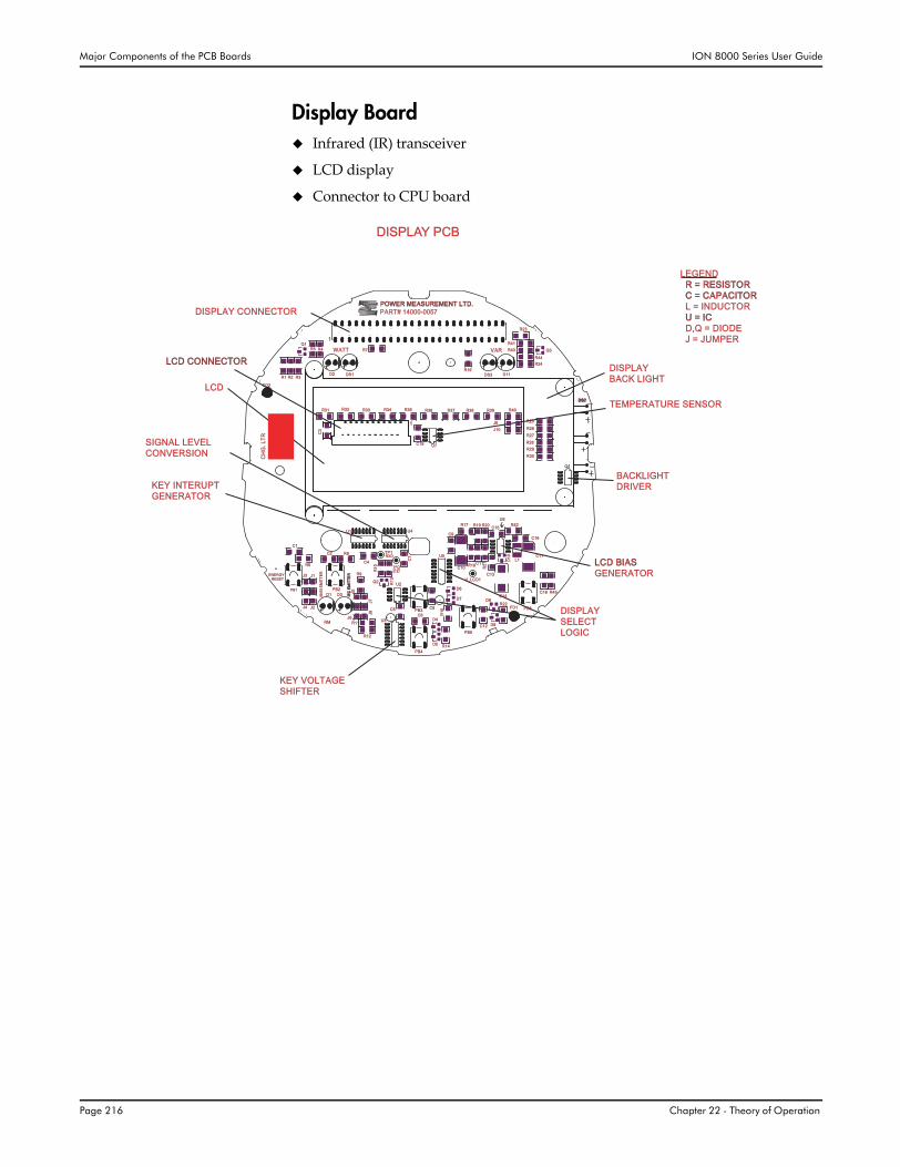
Major Components of the PCB Boards ION 8000 Series User Guide
Page 216 Chapter 22 - Theory of Operation
Display BoardInfrared (IR) transceiver
LCD display
Connector to CPU board
BACKLIGHT
DRIVER
DISPLAY
SELECT
LOGIC
KEY VOLTAGE
SHIFTER
KEY INTERUPT
GENERATOR
SIGNAL LEVEL
CONVERSION
LCD BIASLCD BIAS
GENERATOR
TEMPERATURE SENSOR
LCD
DISPLAY
BACK LIGHT
LEGEND
R = RESISTORR = RESISTOR
C = CAPACITORC = CAPACITOR
L = INDUCTOR
U = ICU = IC
D,Q = DIODE
J = JUMPER
RM
J2
J1
J4
J3
PB1
R6
C1
C2 R8
PB2
D3
J6
J7
J8
R11
R12
U3
C5
C6
PB4
D4
D5R14
R1
5
D7
D6
U5
C8PB3
U2Q2
R1
3
R1
0
TP1
C4
U1 U4
C7
TP
2
R9
J5D1
DS2DS?
C3
D2
R4
Q1
R5
DISPLAY CONNECTOR
DS1
R7
LCD CONNECTORLCD CONNECTORR16
DS3 D11
R44
R43
R41
R23
R24
Q3
R25
R26
R27
R28
R29
R30
R31 R32 R33 R34 R35 R36 R37 R38 R39 R40
J9
J10
Q4
C17L1
C16
R42C15
U6
R2
1C11
R19 R20R17
C10
C9
R18
V_LCD1
C14
D1
0
C13
D9
D8
R22FD1
C12
PB5
PB6
C18 R45
R3R2R1
FD2
C19 U7
CH
G.
LT
R
*
RESET
ENERGY
1
1
AN
SIE
MIT
TE
R
IEC
EM
ITT
ER
IEC
EM
ITT
ER
VARWATT
POWER MEASUREMENT LTD.POWER MEASUREMENT LTD.
PART# 14000-0057
RXD
TX
D
DISPLAY PCB
Page 217
23 Verifying AccuracyAll ION 8000 series meters are tested and verified at the factory according to IEC (International Electrotechnical Commission) standards; however, before a new revenue meter is installed it is important to perform a final accuracy verification.
ION meters are digital and do not require calibration, only verification of their accuracy. This chapter outlines a procedure for accuracy testing ION 8000 series meters.
In this chapter
Introduction . . . . . . . . . . . . . . . . . . . . . . . . . . . . . . . . . . . . . . . . . . . . . . 218Testing Overview . . . . . . . . . . . . . . . . . . . . . . . . . . . . . . . . . . . . . . . . . . . . . . . . . . . . 218Using TEST Mode . . . . . . . . . . . . . . . . . . . . . . . . . . . . . . . . . . . . . . . . . . . . . . . . . . . 219Test Procedure . . . . . . . . . . . . . . . . . . . . . . . . . . . . . . . . . . . . . . . . . . . . . . . . . . . . . . 219Test Settings . . . . . . . . . . . . . . . . . . . . . . . . . . . . . . . . . . . . . . . . . . . . . . . . . . . . . . . . 220
LED pulser settings ............................................................................................. 220Test Points (Standard, Low and ECR Current Meters) .................................. 222
Introduction ION 8000 Series User Guide
Page 218 Chapter 23 - Verifying Accuracy
IntroductionThe revenue-accurate ION meter is digital and therefore needs no servicing. It is tested for accuracy at the factory and remains accurate for the life of the meter. In contrast, electro-mechanical meters need mechanical adjustment before installation and periodic calibration thereafter. This procedure of ‘calibration testing’ is unnecessary for digital meters.
Digital meters require ‘accuracy’ testing, or verification to ensure the meter meets required accuracy specification. If you know your meter is within required accuracy specification before installation, errors observed in the field could be attributed to incorrect connections or instrument transformer ratio settings.
This technical note describes how to test the accuracy of the ION 8000 series meter.
Testing OverviewThe most common method for testing meters is to inject voltage and current from a stable power source in combination with a reference meter. Although meter shops use different methods for testing revenue meters, most test equipment requirements are similar. The sections below provide an overview and some test equipment guidelines for verifying the accuracy of your ION 8000 series meter.
Test socket
A test socket is a convenient mounting device that fits socket-type meters. Ensure that the test socket for the meter or the mounting device is wired properly. The current and voltage transformers must be accurately rated and must perform within specifications to provide accurate results.
Power source
It is important to have a steady power source. Power that energizes the meter from the socket must be reliable and provide: the rated voltage of the meter, unity power factor (1) and lagging power factor of 0.0 (for VARh testing) or 0.5.
Test loads
There are three methods of current loading: customer’s load (a meter in service), resistance load (characteristics similar to a lighting load), phantom loading (a test board). Your test load device or other loading circuit must be set within the current capacity ranges for the meter. The procedure outlined in this technical note describes verification using a phantom load or test board.
Control equipment
Control equipment is required for counting and timing the pulse outputs (revolutions) from the front panel LEDs. Most standard test benches have an arm with infrared sensors used for this purpose.
Environment
The meter should be tested at the same temperature as the testing equipment. The ideal temperature is about 22oC (72oF). Ensure the meter is warmed-up sufficiently before testing.
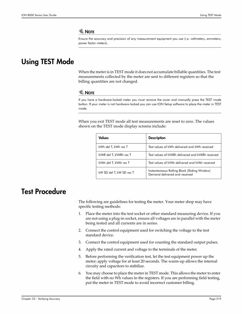
ION 8000 Series User Guide Using TEST Mode
Chapter 23 - Verifying Accuracy Page 219
NOTE
Ensure the accuracy and precision of any measurement equipment you use (i.e. voltmeters, ammeters,power factor meters).
Using TEST ModeWhen the meter is in TEST mode it does not accumulate billable quantities. The test measurements collected by the meter are sent to different registers so that the billing quantities are not changed.
NOTE
If you have a hardware-locked meter you must remove the cover and manually press the TEST modebutton. If your meter is not hardware-locked you can use ION Setup software to place the meter in TESTmode.
When you exit TEST mode all test measurements are reset to zero. The values shown on the TEST mode display screens include:
Test ProcedureThe following are guidelines for testing the meter. Your meter shop may have specific testing methods:
1. Place the meter into the test socket or other standard measuring device. If you are not using a plug-in socket, ensure all voltages are in parallel with the meter being tested and all currents are in series.
2. Connect the control equipment used for switching the voltage to the test standard device.
3. Connect the control equipment used for counting the standard output pulses.
4. Apply the rated current and voltage to the terminals of the meter.
5. Before performing the verification test, let the test equipment power up the meter; apply voltage for at least 20 seconds. The warm-up allows the internal circuity and capacitors to stabilize.
6. You may choose to place the meter in TEST mode. This allows the meter to enter the field with no Wh values in the registers. If you are performing field testing, put the meter in TEST mode to avoid incorrect customer billing.
Values Description
kWh del T, kWh rec T Test values of kWh delivered and kWh received
kVAR del T, kVARh rec T Test values of kVARh delivered and kVARh received
kVAh del T, kVAh rec T Test values of kVAh delivered and kVAh received
kW SD del T, kW SD rec T Instantaneous Rolling Block (Sliding Window) Demand delivered and received
Test Settings ION 8000 Series User Guide
Page 220 Chapter 23 - Verifying Accuracy
7. Align the infrared sensor on the standard test bench armature over the appropriate front panel LED pulser.
TIP
If the outer cover is still on the meter, align the meter sensor slightly off-perpendicular to the LEDs. This reduces reflections from the outer cover.
8. Perform testing on the test points (“Watt-hour test points” and “VAR-hour points” on page 222).
9. Run each test point for at least five seconds to allow the test bench equipment to read an adequate number of pulses. Allow three seconds of dwell time between test points.
Test SettingsWhen testing the meter, ensure the test parameters are suited to your testing methods. You may need to adjust the front panel LED pulse rate and the test mode timeout.
NOTE
If the maximum pulse rate is exceeded the WATT LED remains on (does not blink).
LED pulser settingsThe two LEDs on the front panel are preconfigured for energy pulsing. The adjacent smaller infrared outputs are connected to the LEDs and pulse at the same rate. You may need to increase the Kt value if the LED does not pulse.
Changing the LED pulse rate from the Front Panel
You cannot change the LED pulse rate from the meter’s front panel.
Changing the LED pulse rate in ION Setup
1. Open the Setup Assistant in ION Setup.
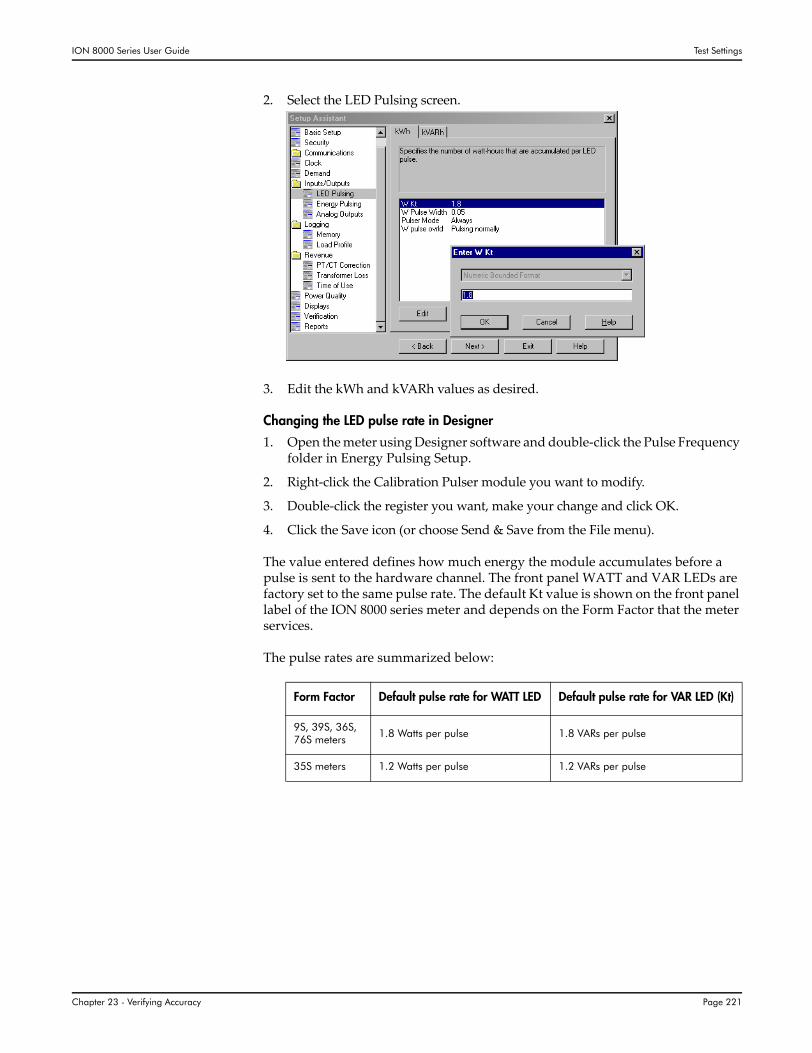
ION 8000 Series User Guide Test Settings
Chapter 23 - Verifying Accuracy Page 221
2. Select the LED Pulsing screen.
3. Edit the kWh and kVARh values as desired.
Changing the LED pulse rate in Designer
1. Open the meter using Designer software and double-click the Pulse Frequency folder in Energy Pulsing Setup.
2. Right-click the Calibration Pulser module you want to modify.
3. Double-click the register you want, make your change and click OK.
4. Click the Save icon (or choose Send & Save from the File menu).
The value entered defines how much energy the module accumulates before a pulse is sent to the hardware channel. The front panel WATT and VAR LEDs are factory set to the same pulse rate. The default Kt value is shown on the front panel label of the ION 8000 series meter and depends on the Form Factor that the meter services.
The pulse rates are summarized below:
Form Factor Default pulse rate for WATT LED Default pulse rate for VAR LED (Kt)
9S, 39S, 36S, 76S meters 1.8 Watts per pulse 1.8 VARs per pulse
35S meters 1.2 Watts per pulse 1.2 VARs per pulse
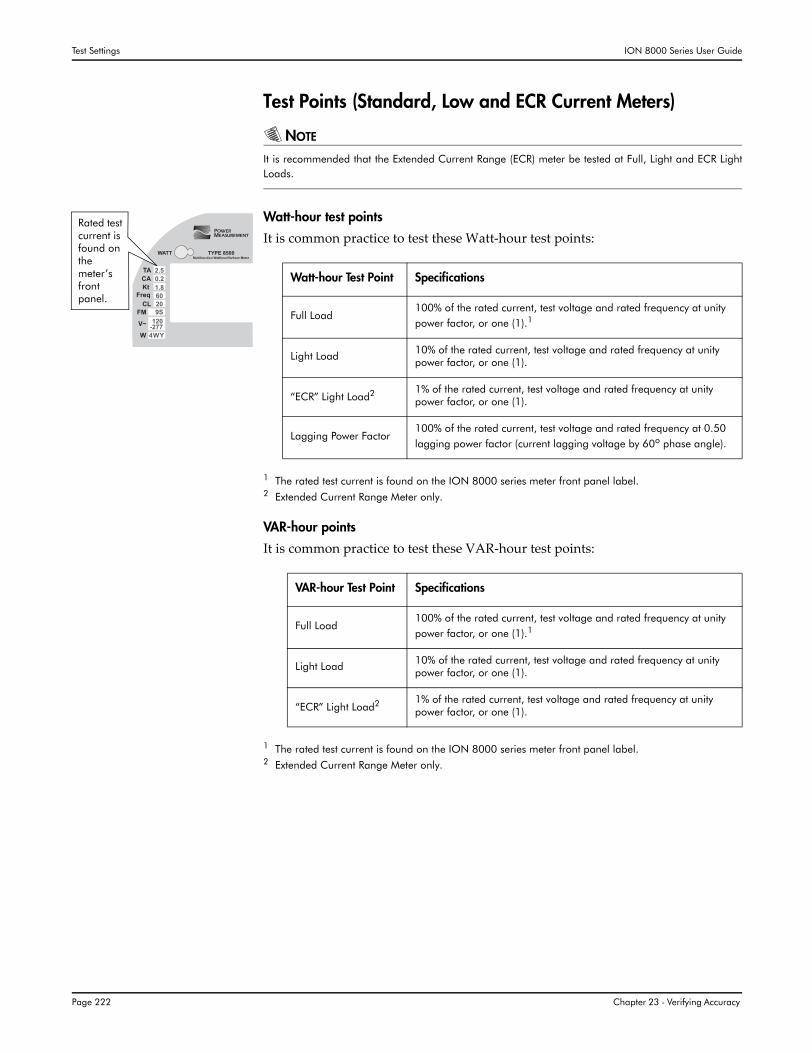
Test Settings ION 8000 Series User Guide
Page 222 Chapter 23 - Verifying Accuracy
Test Points (Standard, Low and ECR Current Meters)
NOTE
It is recommended that the Extended Current Range (ECR) meter be tested at Full, Light and ECR LightLoads.
Watt-hour test points
It is common practice to test these Watt-hour test points:
1 The rated test current is found on the ION 8000 series meter front panel label.2 Extended Current Range Meter only.
VAR-hour points
It is common practice to test these VAR-hour test points:
1 The rated test current is found on the ION 8000 series meter front panel label.2 Extended Current Range Meter only.
Watt-hour Test Point Specifications
Full Load100% of the rated current, test voltage and rated frequency at unity power factor, or one (1).1
Light Load 10% of the rated current, test voltage and rated frequency at unity power factor, or one (1).
“ECR” Light Load2 1% of the rated current, test voltage and rated frequency at unity power factor, or one (1).
Lagging Power Factor100% of the rated current, test voltage and rated frequency at 0.50 lagging power factor (current lagging voltage by 60o phase angle).
VAR-hour Test Point Specifications
Full Load100% of the rated current, test voltage and rated frequency at unity power factor, or one (1).1
Light Load 10% of the rated current, test voltage and rated frequency at unity power factor, or one (1).
“ECR” Light Load2 1% of the rated current, test voltage and rated frequency at unity power factor, or one (1).
WATT
TA
CA
Freq
CL
Kt
2.5
0.2
1.8
60
20
WATT TYPE 8500Multifunction Watthour/Varhour Meter
V~
W
FM
4WY
120-277
9S
Rated test current is found on the meter’s front panel.


MRP: 70000-0193-01Revision Date: November 15, 2004