Embed Size (px)
Citation preview
CHAPTER 15
Dual-temperature Separation
The main disadvantage of conventional ion exchange separation arises from the use ofauxiliary reagents (most often acids or alkalis) in elution and regeneration steps. Theregeneration reagents are sources of environmental pollution unless additional wastetreatment operations (expensive in many cases) are introduced. This problem is not sodramatic for water purification technologies because the amount of wastes produced isvery small in comparison to the volume of water purified. The application of ion exchangefor extraction of chemical substances results in the production of wastes on the sameorder of magnitude as the product itself. Another problem related to the use of auxiliaryreagents is contamination of the product by ions introduced at the elution step.
In many cases, solution to the problem can be found by using parametric separations and,particularly, dual-temperature ion exchange processes. This technique usually exploitsthe temperature dependence of sorbent selectivity towards desired ions. For example, theselectivity of many carboxylic cation exchangers for alkali earth ions strongly dependson temperature. The sorption is performed at the temperature corresponding to higherselectivity. The following temperature change initiates desorption of the accumulatedions and, thus, regeneration of the material. Obviously, this approach is applicable onlyto reversible reactions characterised by relatively high values of �H (for example, dual-temperature separations have been performed on zeolites of different types and crystallinestructures exploiting �H in the range of 15–20 kJ/eq [641]). Both polymeric and inor-ganic ion exchangers are known to be used in such systems. Thus, the method is widelyapplicable. However, it also possesses certain limitations, which will be discussed laterin this chapter.
315

316 Ion Exchange Materials: Properties and Applications
15.1 Parametric Elution
All methods described in the previous chapters use external reagents to strip target ionsfrom the exchanger. For example, if the cation exchange reaction
RA1 + A2 + other species = RA2 + A1 + other species (15.1)177
describes the sorption step, the ion A2 should be eluted using another ion (an externalreagent)
RA2 + A3 + Y1 = RA3 + A2 + Y1 (15.2)
where Y1 is a co-ion. The regeneration
RA3 + A1 + Y2 = RA1 + A3 + Y2 (15.3)
is performed to obtain the initial A1 form of the exchanger. The process requires theintroduction of external salts A3Y1 and A1Y2. Reactions (15.2) and (15.3) can be combinedin one step; however, the introduction of an external substance (in this case, A1Y1 orA1Y2) cannot be eliminated.
Parametric approaches have received attention due to the possibility of reversing reaction(15.1) without the introduction of any external substance. Reversing of the equilibriumforward and backward can be induced by periodical changing of a thermodynamic vari-able, i.e. temperature or pressure, that affects the equilibrium distribution of the sorbedmaterial between the liquid and solid phases. The simplest case of such a separation isshown in Fig. 15.1.
The idea of parametric ion exchange separation is based on the general thermo-dynamic description of chemical reactions. Equilibrium (15.1) is characterised by thethermodynamic constant
K = aRA2· aA1
aRA1· aA2
(15.4)
that depends on temperature and pressure:
d
dTln K
∣∣∣∣P
= �Ho
RT 2(15.5)
d
dPln K
∣∣∣∣T
= �Vo
RT 2(15.6)
177Subscripts in this and the following equations indicate the numbering of ions, and not the number of ionsin the molecule.

Dual-temperature Separation 317
Purifiedsolvent
Des
orpt
ion
at T
Sorp
tion
at T
Rawsolution
Concentratedions
1 2
Temperature cycle
Fig. 15.1. Simplest cycle of dual-temperature ion exchange separation. The same raw solution ispumped through the column. The temperature is altered between T1 and T2. T1 corresponds to ahigher affinity towards the target ion and, thus, corresponds to the sorption half-cycle. Desorptionhappens at T2, which corresponds to the reduced affinity.
where T is absolute temperature, �Ho is reaction enthalpy, P is pressure, and �Vo isthe change of the system volume. Unfortunately, ion exchange processes are not accom-panied by significant volume changes, i.e. �Vo→0. Thus, the pressure dependenciesdescribed by Eq. (15.6) are small and, hence, cannot be efficiently used to reverse mostof the ion exchange reactions. In contrast, the temperature dependence (15.5) can beexploited in a number of cases.
A straightforward separation process with parametric elution is often referred to as thetemperature-swing mode. The separation is performed according to Fig. 15.1 and isdynamically illustrated by Applet 14.178 The treated solution is pumped continuouslyinto the bed of the ion exchanger in a mixed ionic form of the same ions as those inthe solution.179 After accomplishing the step, the temperature of the column is changedalternately from “cold” to “hot” and vice versa. Throughout the process, the flow of thesolution is divided into two parts: one is collected during the “cold” stage of the processand another in the “hot” stage. The concentration ratio of the separated componentsdiffers for the two obtained solutions [641]. In case of only two ions present in thesolution, one of the collected fractions is enriched with one ion and depleted in another.The second fraction contains the opposite ratio of ionic concentrations.
178http://ionexchange.books.kth.se/applet14.html179When the first separation cycle is started, any suitable ionic form can be used. For example, if the firststage of the cycle has to remove cations and emit hydrogen instead, H+ form of the cation exchanger wouldbe most suitable.
318 Ion Exchange Materials: Properties and Applications
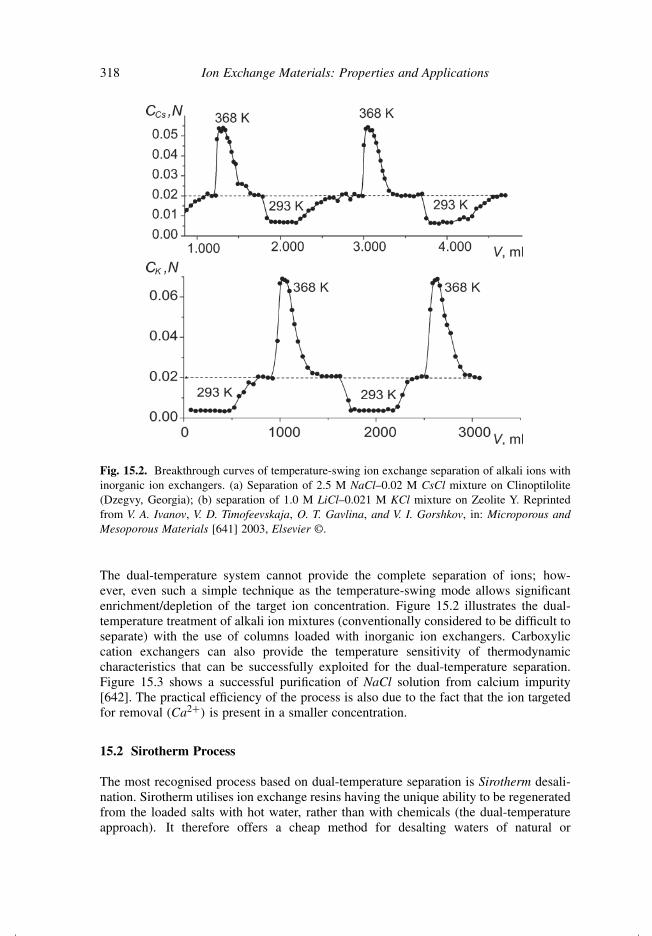
Fig. 15.2. Breakthrough curves of temperature-swing ion exchange separation of alkali ions withinorganic ion exchangers. (a) Separation of 2.5 M NaCl–0.02 M CsCl mixture on Clinoptilolite(Dzegvy, Georgia); (b) separation of 1.0 M LiCl–0.021 M KCl mixture on Zeolite Y. Reprintedfrom V. A. Ivanov, V. D. Timofeevskaja, O. T. Gavlina, and V. I. Gorshkov, in: Microporous andMesoporous Materials [641] 2003, Elsevier ©.
The dual-temperature system cannot provide the complete separation of ions; how-ever, even such a simple technique as the temperature-swing mode allows significantenrichment/depletion of the target ion concentration. Figure 15.2 illustrates the dual-temperature treatment of alkali ion mixtures (conventionally considered to be difficult toseparate) with the use of columns loaded with inorganic ion exchangers. Carboxyliccation exchangers can also provide the temperature sensitivity of thermodynamiccharacteristics that can be successfully exploited for the dual-temperature separation.Figure 15.3 shows a successful purification of NaCl solution from calcium impurity[642]. The practical efficiency of the process is also due to the fact that the ion targetedfor removal (Ca2+) is present in a smaller concentration.
15.2 Sirotherm Process
The most recognised process based on dual-temperature separation is Sirotherm desali-nation. Sirotherm utilises ion exchange resins having the unique ability to be regeneratedfrom the loaded salts with hot water, rather than with chemicals (the dual-temperatureapproach). It therefore offers a cheap method for desalting waters of natural or

Dual-temperature Separation 319
0.125
0.100
0.075
0.050
0.025
0 2 4 6 8
1
2
1
V,
CCa,N
Fig. 15.3. Purification of 2.5 M NaCl from impurity of calcium (0.01 M Ca2+). The ion exchangeris KB-4 (gel-type polymethacrylic resin with 6% of divinylbenzene cross-linking). Please notethat the plot shows the results of experimental runs. As explained in Section 11.2, practical cyclicoperations do not suggest such perfection in loading of the column at purification half-cycles(curves 1). Reprinted from V. A. Ivanov, V. D. Timofeevskaja, and V. I. Gorshkov, Reactive Polymers[642] 1992, Elsevier ©.
industrial origin. It also has an environmental advantage over the conventional chemi-cally regenerated systems in that the amount of waste salt discharged in the effluent issubstantially reduced. For example, water containing 1000 mg/L of sodium chloride canbe treated to bring the salt content down to the potable limit of 500 mg/L, with a yieldof 85%. The remaining 15% of the feed water is used as the regenerant at 80◦C. Theaverage effluent concentration is 3800 mg/L, which includes the salt stripped from theion exchanger. The process is effective on waters having up to 3000 mg/L of dissolvedsalts and, because no chemicals are necessary in the normal sense, it is competitive(depending on the raw water composition) with other processes, such as reverse osmo-sis, electrodialysis, and conventional ion exchange. It is not suitable for treating moreconcentrated water such as seawater, which has a salt content of 35,000 mg/L [643].
The Sirotherm process is performed on specially designed carboxylic resin. The metalions are sorbed from the treated water at ambient temperature and stripped by the samefeed water at elevated temperature (see Fig. 15.1). To explain the physico-chemicalprinciple, let us consider interactions in the system. The solution is pumped through thecolumn at ambient temperature. The sorption process can be written as
2R − COO− + 2H+ + Ca2+ = 2R − COO− + Ca2+ + 2H+ (15.7)180
180Reaction (15.7) is written for ion exchange of Ca2+. Exactly the same can be written for magnesiumbecause the considered water treatment usually targets these two ions together.
320 Ion Exchange Materials: Properties and Applications
and is characterised by the corresponding reaction constant
˜̃KCa
H =[Ca2+
][H+]2
[H+
]2 [Ca2+](15.8)
The value of this constant does not depend on temperature enough to make the processthermoreversible. Nevertheless, the same water can successfully regenerate the sorbentat an elevated temperature. To explain it, all reactions taking place on the system mustbe considered. The temperature increase boosts the water dissociation
H2O = H+ + OH− (15.9)
The temperature dependence of the corresponding dissociation constant
˜̃KW = [H+][OH−] (15.10)
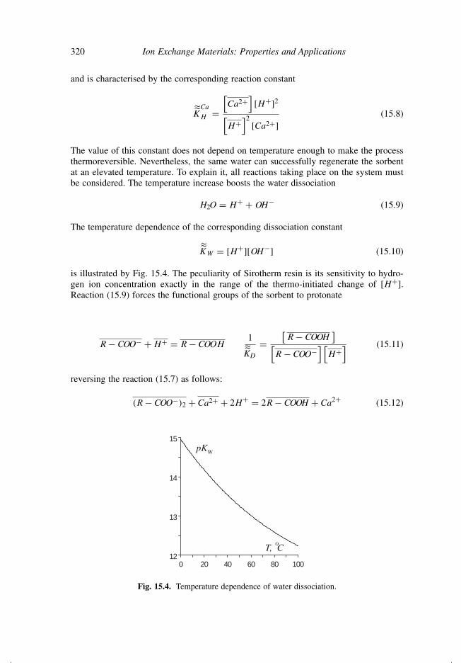
is illustrated by Fig. 15.4. The peculiarity of Sirotherm resin is its sensitivity to hydro-gen ion concentration exactly in the range of the thermo-initiated change of [H+].Reaction (15.9) forces the functional groups of the sorbent to protonate
R − COO− + H+ = R − COOH1
˜̃KD
=[R − COOH
][R − COO−
] [H+
] (15.11)
reversing the reaction (15.7) as follows:
(R − COO−)2 + Ca2+ + 2H+ = 2R − COOH + Ca2+ (15.12)
0 20 40 60 80 100
12
13
14
15
pK
T, Co
W
Fig. 15.4. Temperature dependence of water dissociation.
Dual-temperature Separation 321
Please note the difference between reaction (15.7) and reversed reaction (15.12). Thisdifference illustrates the two different states of Sirotherm functional groups: protonatedand deprotonated.
The discussed thermal regeneration process can be described by the followingmechanism:
• The increase of temperature initiates production of hydrogen ions through reac-tion (15.9).
• The hydrogen ions produced participate in reaction (15.11), protonating carboxylicgroups of the resin.
• The reaction (15.11) removes charged carboxylic groups from the overall equilib-rium (15.1), causing desorption of calcium ions.
The summarised reaction of regeneration can be written as
2R − COO− + Ca2+ + 2H2O = 2R − COOH + Ca2+ + 2OH− (15.13)
The reaction (15.13) is characterised by the reversed separation factor αCaH that can be
written as a combination of constants (15.8), (15.10), and (15.11):
1
αCaH
=[R − COOH
]2 [Ca2+] [
OH−]2
[R − COO−
]2 [Ca2+
] =˜̃KCa
H · ˜̃K2
D
˜̃K2
W
(15.14)
Expression (15.14) shows that the temperature changes strongly affect the separationfactor due to the square power dependence of α on the constant of water dissociation.
While being highly successful, the Sirotherm process has its specific area of applicationand cannot be easily extended to other separation needs. The reason is that the speciallydesigned Sirotherm resins provide selectivity only towards certain types of ions. Thesematerials have a narrow work interval of pH that limits their applicability even more.
One has to note that the name Sirotherm is often applied nowadays to other dual-temperature processes that do not actually exploit the same chemical phenomena.
15.3 Principle of Parametric Pumping
Parametric pumping is a special technique introduced in 1966 [644]. It allows the use ofsorption systems of low selectivity and low temperature sensitivity in dual-temperatureseparations. The simplest variant consists of splitting the treated solution into two equalvolumes. The volumes are repeatedly in contact with an ion exchanger in a periodicallychanging way. Separation is carried out by altering an external parameter (temperature,

322 Ion Exchange Materials: Properties and Applications
pH value, ionic strength, chemical potential, etc.) that affects the sorption equilibrium.By synchronising the periodical alterations of this parameter with the changing of the con-tacting half-volumes, some dissolved components are transported into one half-volumewhile other components are transported in the opposite direction. The most importantfeature of this process is the elimination of the need for external chemicals [645].181 Theperiodical process eventually results in a steady-state concentration difference betweentwo half-volumes [646]. To demonstrate how the parametric pumping works, let us con-sider the simple scheme presented in Fig. 15.5. The process is performed in batch; nocolumn is involved. An exchanger shuttle (in small-scale laboratory experiments, theshuttle can look like a tea bag) is transported between two stirred reservoirs kept atdifferent temperatures. At the beginning of the experiment, the reservoirs are filled withthe same solution containing counterions A and B. The ion exchange is described by thereaction
RB + A = RA + B (15.15)
˜̃KA
B =[RA
][B][RB
][A] (15.16)
Fig. 15.5. Batch parametric pumping (“tea bag” mode). The shuttle is contacted in turn withsolutions kept at different temperatures. The repeated procedure redistributes ions between the tworeservoirs.
181As a matter of fact, if pH, ionic strength, or chemical potential is the altered parameter, the correspondingchemicals are introduced into the system. However, quantities of these periodic additions are much less thanthe quantities needed for conventional regeneration.
Dual-temperature Separation 323
0.0 0.5 1.0
X
0.5
1.0
X
2
3
4
5
6
7
89
1
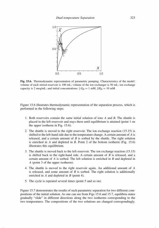
Fig. 15.6. Thermodynamic representation of parametric pumping. Characteristics of the model:volume of each stirred reservoir is 100 mL; volume of the ion exchanger is 50 mL; ion exchangecapacity is 2 meq/mL; and initial concentrations: [A]0 = 1 mM, [B]0 = 10 mM.
Figure 15.6 illustrates thermodynamic representation of the separation process, which isperformed in the following steps:
1. Both reservoirs contain the same initial solution of ions A and B. The shuttle isplaced in the left reservoir and stays there until equilibrium is attained (point 1 onthe upper isotherm in Fig. 15.6).
2. The shuttle is moved to the right reservoir. The ion exchange reaction (15.15) isshifted to the left-hand side due to the temperature change. A certain amount of A isreleased, and a certain amount of B is sorbed by the shuttle. The right solutionis enriched in A and depleted in B. Point 2 of the bottom isotherm (Fig. 15.6)illustrates this equilibrium.
3. The shuttle is moved back to the left reservoir. The ion exchange reaction (15.15)is shifted back to the right-hand side. A certain amount of B is released, and acertain amount of A is sorbed. The left solution is enriched in B and depleted inA (point 3 of the upper isotherm).
4. The shuttle is moved to the right reservoir again. An additional amount of A
is released, and some amount of B is sorbed. The right solution is additionallyenriched in A and depleted in B (point 4).
5. The cycle is repeated several times (point 5 and so on).
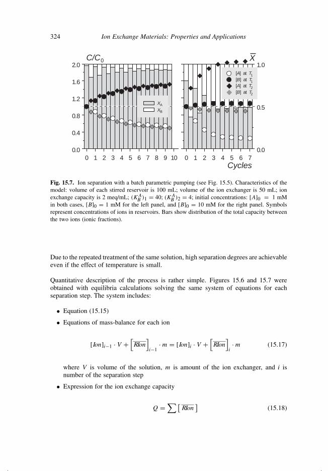
Figure 15.7 demonstrates the results of such parametric separation for two different com-positions of the initial solution. As one can see from Figs 15.6 and 15.7, equilibria statesgradually “slide” in different directions along the two isotherms corresponding to thetwo temperatures. The compositions of the two solutions are changed correspondingly.
324 Ion Exchange Materials: Properties and Applications
0 1 2 3 4 5 6 7 8 9 10
0.0
0.4
0.8
1.2
1.6
2.0
0 1 2 3 4 5 6 7
0.0
0.5
1.0
Cycles
XC/C0
XA
XB
[A] at T1
[B] at T1
[A] at T2
[B] at T2
Fig. 15.7. Ion separation with a batch parametric pumping (see Fig. 15.5). Characteristics of themodel: volume of each stirred reservoir is 100 mL; volume of the ion exchanger is 50 mL; ionexchange capacity is 2 meq/mL; (KA
B )1 = 40; (KAB )2 = 4; initial concentrations: [A]0 = 1 mM
in both cases, [B]0 = 1 mM for the left panel, and [B]0 = 10 mM for the right panel. Symbolsrepresent concentrations of ions in reservoirs. Bars show distribution of the total capacity betweenthe two ions (ionic fractions).
Due to the repeated treatment of the same solution, high separation degrees are achievableeven if the effect of temperature is small.
Quantitative description of the process is rather simple. Figures 15.6 and 15.7 wereobtained with equilibria calculations solving the same system of equations for eachseparation step. The system includes:
• Equation (15.15)
• Equations of mass-balance for each ion
[Ion]i−1 · V +[RIon
]i−1
· m = [Ion]i · V +[RIon
]i· m (15.17)
where V is volume of the solution, m is amount of the ion exchanger, and i isnumber of the separation step
• Expression for the ion exchange capacity
Q =∑ [
RIon]
(15.18)
Dual-temperature Separation 325
If the number of cycles is sufficient, the separation limit can be achieved. The limitcan be defined as shown in the following. Equation (15.16) can be written for the tworeservoirs of Fig. 15.5 as
(˜̃KA
B )1 =[RA
]1 [B]1[
RB]
1 [A]1(15.19)
(˜̃KA
B )2 =[RA
]2 [B]2[
RB]
2 [A]2(15.20)
The separation limit is achieved when there is no exchange between the material andany of the two solutions, i.e. when both Eqs (15.19) and (15.20) are fulfilled at the samecomposition of the exchanger:
[RA
]1[
RB]
1
=[RA
]2[
RB]
2
(15.21)
Combination of Eqs (15.19)–(15.21) gives
(˜̃KA
B)1[A]1
[B]1= (˜̃KA
B )2[A]2
[B]2(15.22)
Expression (15.22) shows that the thermodynamic separation limit is achieved if thedifference between the equilibria constants (at different temperatures) is compensated bydifference in the ionic ratio. Please note that the limit can be achieved independently onthe ratio between the amount of the exchanger and the volume of the treated solution.However, a larger solution/exchanger ratio results in a higher number of steps needed toachieve the same separation degree.
Separation of two ions between two reservoirs is the simplest case. More complicatedionic mixtures can be separated according to the temperature response of the involvedselectivity characteristics. Also, the direction of separation with parametric pumpingcould be different for the same or similar solutes, depending on the selected system andoperating conditions. For example, the separation of several amino acids in the presenceof 1 M HCl on Dowex 50 × 8 (styrene–divinylbenzene cation exchanger with sulphonicgroups) resulted in concentrating of all amino acids in one reservoir [647] while underother conditions the same system (1 M HCl and Dowex 50 × 8) allowed the separationof proline from valine, and phenylalanine from leucine and valine [648]. To achieveefficient separations, additional reagents can be introduced to enhance the temperatureresponse of the overall system. For example, a number of successful studies have beenpublished on parametric pumping with the addition of complexing agents [645,649–651].

326 Ion Exchange Materials: Properties and Applications
Fig. 15.8. Column systems for parametric pumping altering: (a) pH; (b) temperature; (c) pressure.(1) Conventional ion exchange column; (2) and (3) bottom and top stirred reservoirs; (4) reversiblepump; (5) acidic buffer; (6) alkaline buffer; (7) thermostated ion exchange column; (8) double-temperature thermostat; (9) pressure source with on–off valve.
15.4 Parametric Pumping in Columns
Different modes of column parametric pumping are shown in Fig. 15.8.182 The operationis visualised by Applet 15.183 The ion exchange column is connected to two reservoirs.The cycle consists of pumping of the solution through the bed alternatively from thebottom reservoir to the top and from the top reservoir to the bottom.184 The temperatureor another external parameter is changed synchronously with the flow direction. One ofthe solutes or a group of solutes is concentrated preferentially in the top reservoir andthe other in the bottom reservoir. There are cases where all solutes are concentrated inone reservoir and depleted in another.
Figure 15.9 shows different stages of the process and gives a more conventional illustra-tion of the corresponding isotherms (in comparison to Fig. 15.6). Equilibrium conditionsat each point of the column and at each moment of time are assumed. This process isconsidered as consisting of four repeated steps [647,648,652,654]. The illustration has
182The column systems shown in Fig. 15.8 are often referred to as batch parametric pumping. Using of thisterm here could be confusing. The tea bag experiment described earlier (Fig. 15.5) represents truly batchinteractions in each step of the process. The separation according to Fig. 15.8 is performed in the closedsystem, while each step of the separation is not a batch but a column operation. Hence, it must be regarded asclosed parametric pumping to distinguish between the tea bag and column methods.183http://ionexchange.books.kth.se/applet15.html184Two reservoirs of the parametric pumping system are conventionally designated as top and bottom, whiletheir actual positioning has no special importance.
Dual-temperature Separation 327
A
BD
C
E
T2
T1
X2 X0 X10
1
1
(C2) (C0) (C1)
T1
C0
C0
C0
A
A
i
C1
C1
C0
B
B
ii
T2
C1
C0
C1
B
C
iii
C0
C2
C1
A
D
iv
T1
C1
C2
C2
C0
E
D
v
T2
T1T1
T2
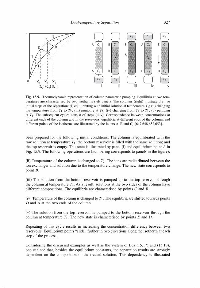
Fig. 15.9. Thermodynamic representation of column parametric pumping. Equilibria at two tem-peratures are characterised by two isotherms (left panel). The columns (right) illustrate the fiveinitial steps of the separation: (i) equilibrating with initial solution at temperature T1; (ii) changingthe temperature from T1 to T2; (iii) pumping at T2; (iv) changing from T2 to T1; (v) pumpingat T1. The subsequent cycles consist of steps (ii–v). Correspondence between concentrations atdifferent ends of the column and in the reservoirs, equilibria at different ends of the column, anddifferent points of the isotherms are illustrated by the letters A–E and Ci [647,648,652,653].
been prepared for the following initial conditions. The column is equilibrated with theraw solution at temperature T1; the bottom reservoir is filled with the same solution; andthe top reservoir is empty. This state is illustrated by panel (i) and equilibrium point A inFig. 15.9. The following operations are (numbering corresponds to panels in the figure):
(ii) Temperature of the column is changed to T2. The ions are redistributed between theion exchanger and solution due to the temperature change. The new state corresponds topoint B.
(iii) The solution from the bottom reservoir is pumped up to the top reservoir throughthe column at temperature T2. As a result, solutions at the two sides of the column havedifferent compositions. The equilibria are characterised by points C and B.
(iv) Temperature of the column is changed to T1. The equilibria are shifted towards pointsD and A at the two ends of the column.
(v) The solution from the top reservoir is pumped to the bottom reservoir through thecolumn at temperature T1. The new state is characterised by points E and D.
Repeating of this cycle results in increasing the concentration difference between tworeservoirs. Equilibrium points “slide” further in two directions along the isotherm at eachstep of the process.
Considering the discussed examples as well as the system of Eqs (15.17) and (15.18),one can see that, besides the equilibrium constants, the separation results are stronglydependent on the composition of the treated solution, This dependency is illustrated

328 Ion Exchange Materials: Properties and Applications
by the two panels of Fig. 15.7 (Section 15.3). The right panel demonstrates a betterseparation of the minor constitute A between two solutions at the expense of the majorconstitute B.
Dependency of the separation efficiency on distribution of the solution between twovolumes can be exploited in the following way. Increasing of one reservoir to infinityallows the most significant enrichment (or depletion, if purification of the solvent/solutionis targeted) of the target ion in the second reservoir. Of course, no infinite tank is used.Fresh portions of the solution are supplied in the first reservoir instead. The result ofsuch separation is illustrated in Fig. 15.10. Such a scheme is called half-open or semi-continuous parametric pumping. The system operates similarly to the closed systemduring one half-cycle and continuously during the other half-cycle.
Many authors apply the equilibrium scheme to the column separation. However, suchequilibrium treatment suggests significant simplifications and are applicable for illus-tration rather than for quantitative treatment of the column process. In practice, theseparation is defined by complicated concentration profiles formed inside the column.The profile formation could be specific to the discussed technique because ions migrateinside the column in alternate directions. Following the course of a single ion of the solutewould result in the path illustrated in Fig. 15.11. The ion is transported in the direction
0 2 4 6 8 10 12 14 16
0
1
2
3
4
5
0.0
0.5
1.0
C/C0 X
Cycles
XA
XB
[A] at T2
[B] at T2
[B] at T1
[A] at T1
Fig. 15.10. Ion separation with half-open parametric pumping (batch mode). Characteristics ofthe model: volume of the closed reservoir is 100 mL; volume of the ion exchanger is 50 mL;
ion exchange capacity is 2 meq/mL; (˜̃KA
B )1 = 40; (˜̃KA
B)2 = 4; initial concentrations: [A]0 = 1 mMand [B]0 = 10 mM. The bars show distribution of the total capacity (ionic fractions) betweentwo ions.
Dual-temperature Separation 329
HOT FLOW
COLD FLOW
HOT
COLD
HOT
COLD
HOT
COLD
HOT
COLD
HOT
COLD
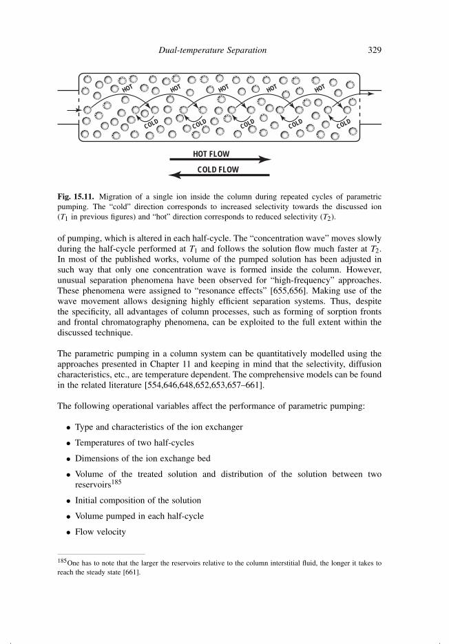
Fig. 15.11. Migration of a single ion inside the column during repeated cycles of parametricpumping. The “cold” direction corresponds to increased selectivity towards the discussed ion(T1 in previous figures) and “hot” direction corresponds to reduced selectivity (T2).
of pumping, which is altered in each half-cycle. The “concentration wave” moves slowlyduring the half-cycle performed at T1 and follows the solution flow much faster at T2.In most of the published works, volume of the pumped solution has been adjusted insuch way that only one concentration wave is formed inside the column. However,unusual separation phenomena have been observed for “high-frequency” approaches.These phenomena were assigned to “resonance effects” [655,656]. Making use of thewave movement allows designing highly efficient separation systems. Thus, despitethe specificity, all advantages of column processes, such as forming of sorption frontsand frontal chromatography phenomena, can be exploited to the full extent within thediscussed technique.
The parametric pumping in a column system can be quantitatively modelled using theapproaches presented in Chapter 11 and keeping in mind that the selectivity, diffusioncharacteristics, etc., are temperature dependent. The comprehensive models can be foundin the related literature [554,646,648,652,653,657–661].
The following operational variables affect the performance of parametric pumping:
• Type and characteristics of the ion exchanger
• Temperatures of two half-cycles
• Dimensions of the ion exchange bed
• Volume of the treated solution and distribution of the solution between tworeservoirs185
• Initial composition of the solution
• Volume pumped in each half-cycle
• Flow velocity
185One has to note that the larger the reservoirs relative to the column interstitial fluid, the longer it takes toreach the steady state [661].

330 Ion Exchange Materials: Properties and Applications
If the system operates in non-equilibrium conditions (i.e. the pumping rate is too fast toachieve equilibria at each point in the bed), the time spent for temperature altering mustalso be considered as a major variable.
The column parametric pumping can be successfully used in combination with con-ventional elution techniques for complete separation of complicated ionic mixtures. Aswas said earlier, a steady state is achieved after a number of half-cycles. In many cases,adjustment of operating conditions allows the distribution of the constitutes of the mixtureinside the column in such way that a steady periodic wave pattern is established [554].In most successful cases, concentration profiles of different components do not over-lap each other. The opportunity for complete separation comes when the positioningof different components inside the column follows the selectivity range of the ionexchanger towards these solutes, which can happen if the selectivity series186 is notaltered with the temperature change. If distributed in such manner, the components canbe recovered in pure form by elution with a suitable reagent. Such combined techniquesrequire much shorter columns and much less eluent in comparison to conventional elutionchromatography.
The main disadvantage of closed and half-open parametric pumping is the significanttime and energy expenses at low productivity. The main advantage is that the wholeseparation process is performed in a confined system without the introduction of addi-tional chemical substances, i.e. no eluent can contaminate either of the two products.The method provides high separation efficiency; however, it is not well-suited for morethan a laboratory scale. As the result, applications of parametric pumping are mainlylimited to preparation of high-purity chemicals.
One has to note that parametric pumping is not a technique that specifically uses ionexchange materials. Other types of sorbents are also successfully exploited [644]. Besidesthe “tea bag” and column systems, the successful use of membrane units has also beendescribed [662,663].
15.5 Continuous (Open) Parametric Pumping
The closed and semi-continuous systems discussed earlier are well suited for the process-ing of small volumes. If larger-scale operations are required, some type of continuousprocess must be considered [554]. Open systems are operated in such a way that thefeed is injected and the products are removed in a continuous or semi-continuous way[661]. Many variants of continuous parametric pumping have been reported. These sys-tems usually differ from each other according to how and when the feed is introduced[554,661].
Figure 15.12 represents such a scheme, with the feed introduced at one end of the column.The column takes a feed stream and separates it into two products collected at differenttemperatures at two sides of the column. At the first temperature, the flow of the rawsolution and the flow coming from one reservoir (upper reservoir in Fig. 15.12) are fed
186The concept of selectivity series was discussed in Section 8.4.
Dual-temperature Separation 331
Raw
solution
Product 1
T1
Raw
solution
T1 T1
Product 2
T2 T2
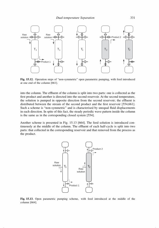
Fig. 15.12. Operation steps of “non-symmetric” open parametric pumping, with feed introducedat one end of the column [661].
into the column. The effluent of the column is split into two parts: one is collected as thefirst product and another is directed into the second reservoir. At the second temperature,the solution is pumped in opposite direction from the second reservoir; the effluent isdistributed between the stream of the second product and the first reservoir [554,661].Such a scheme is “non-symmetric” and is characterised by unequal fluid displacementsin each direction. In spite of this fact, the steady periodic wave pattern inside the columnis the same as in the corresponding closed system [554].
Another scheme is presented in Fig. 15.13 [664]. The feed solution is introduced con-tinuously at the middle of the column. The effluent of each half-cycle is split into twoparts: that collected in the corresponding reservoir and that removed from the process asthe product.
Raw
solution
Product 1
T1Raw
solution
T2
Product 2
Fig. 15.13. Open parametric pumping scheme, with feed introduced at the middle of thecolumn [664].

332 Ion Exchange Materials: Properties and Applications
More “non-symmetric” and “symmetric” schemes of open parametric pumping can befound in the literature. All variations include reservoirs for partial or complete collectionof the treated solution. This allows the repeated treatment of the solution, providingan increase in the separation degree. If two separation experiments are compared, theone with smaller fraction of the solution collected in the reservoirs will yield lowerseparation efficiency while processing a larger volume of the raw solution during thesame time period. A system without reservoirs can be considered as a limiting case.The raw solution is pumped in two directions at different temperatures. The effluentscoming at each temperature are the two products. Such a scheme is the simplest caseof open parametric pumping [644], while it is also a dual-temperature separation withcountercurrent thermal regeneration.187 Another limiting case is the closed parametricpumping (see Section 15.3), where all solution is pumped between two reservoirs, andthe thermodynamic separation limit is achievable.
15.6 Rocking Wave Separation
The rocking wave separation [665–667] is a relatively new dual-temperature separationmethod. To explain its concept, let us consider the following separation system. A certainamount of the target substance is introduced in an ion exchange column. The amountof substance is significantly lesser than the ion exchange capacity of the bed. Thus, dueto the conventional chromatographic process, the substance is distributed inside the col-umn as a concentration profile that can be depicted as a wave (panel a of Fig. 15.14).When the solution is pumped, each point of the curve travels a certain distance alongthe column. Concentrating of the target substance can be achieved if the column con-sists of two parts kept at different temperatures T1 and T2, and thus characterised byλ1 < λ2, respectively.188 As one can see, point (b) of the curve travels a longer distanceat temperature T1, while most of the travelling of point (f) happens at temperature T2. Aswas discussed in Chapter 11, higher selectivity (larger λ) causes slower travelling of thetarget substance. Thus, the travelling distance xf is shorter than xb(xb > x > xf ), whichresults in reduction of the wave span and increase in the concentration. If the pumpingdirection is reversed and the temperatures in the two parts of the column are altered, thesame process can be repeated and the concentration can be increased again. Alternatingthe pumping direction causes “rocking” of the wave between the two parts of the column,which is accompanied by temperature-induced concentrating of the target substance.
Keeping two parts of the column at different temperatures is obviously a difficult task.Two-column systems can be used instead. Such a scheme of the rocking wave separationis shown in Fig. 15.15. The system consists of two ion exchange columns (1 and 2),a heat exchanger (3), heating/cooling devices (4, 5), a number of valves, and a reversiblepump. The solution is pumped in a looped circuit. Each separation cycle consists of threesteps. Initial state could be equilibrium between the solution and ion exchanger in both
187The countercurrent regeneration has been discussed earlier in Section 12.1.188λ is the distribution coefficient (see Eq. (8.22) in Section 8.4). The method is described here in simpleterms of the distribution coefficient instead of values more suitable to characterise ion exchange interactions(see Table 8.1) because the method is not limited by only ion exchange processes and can be applied to anytemperature-sensitive sorption system.

x
T1T2
x
xf xb
(a)
T1 T2
x
xfxb
(b)
fb
fb
Fig. 15.14. Principle of rocking wave dual-temperature separation. The white and grey back-grounds indicate parts of the column kept at different temperatures. Dashed curves indicateconcentration profiles before (in white area) and after (in grey area) of each separation cycle. x isthe longitudinal coordinate of the column. The temperature T1 corresponds to the lower affinity ofthe sorbent to the target substance; T2 corresponds to the higher affinity. Arrows indicate directionof the solution flow, as well as distances passed by different parts of the concentration wave.
T1 T2
Step 2
T1T2
Step 1
T2
Step 3
T2T1
Rawsolution
1 2Product
34
56
Fig. 15.15. Practical scheme of rocking wave separation. (1), (2) Ion exchange columns; (3) heatexchanger; (4), (5) heating/cooling devices; (6) valve for collection of the product. Valves dis-connecting particular units from the loop and the reversible pump are not shown for simplicity.The temperature T1 corresponds to the lower affinity of the sorbent to the target substance (whitebackground); T2 corresponds to the higher affinity (grey background).

334 Ion Exchange Materials: Properties and Applications
columns at T2, i.e. at the temperature corresponding to a higher λ. After the equilibrationtemperature of the column 1 is changed to T1, the cyclic operation is started.
• Step 1 includes transfer of the target substance from column 1 to column 2. This pro-cess has been discussed earlier and is illustrated in Fig. 15.14. The heat exchangerbetween the columns allows keeping solutions and columns at desired tempera-tures, in addition to providing recuperation of the thermal energy. The unavoidableheat dispersion (around 15%) is compensated for by the heating/cooling devices.The flow transfers a certain amount of the substance from column 1 to column 2,simultaneously increasing its maximum concentration.
• Step 2 consists of shifting the temperature distribution along the loop. In contrastto other dual-temperature techniques, the heat is not directly supplied to jacketedcolumns but transferred with the circular flow of the solution. The temperaturefront proceeds along the column at a much faster rate than the wave. Thus, thewave movement during Step 2 is short. The temperature change also causes partialredistribution of the target substance that is transferred from the exchanger in thesolution; however, the overall content of the substance in the cross section of thecolumn remains unchanged.
• During Step 3, first column is disconnected from the loop and is loaded with anadditional amount of the target substance by pumping the raw solution. All otherparts of the system are kept idle.
The subsequent cycle is performed in the same way, while the direction of the pumpingand temperatures of the columns are altered.
Several cycles of the process allow accumulating the target product in one highly con-centrated wave. This makes the system ready for providing the concentrated product.When the highest concentration of the product passes valve 6 (during Step 1), the valveis opened and the product collected. Thus, the system allows collecting the product atits highest possible concentration.
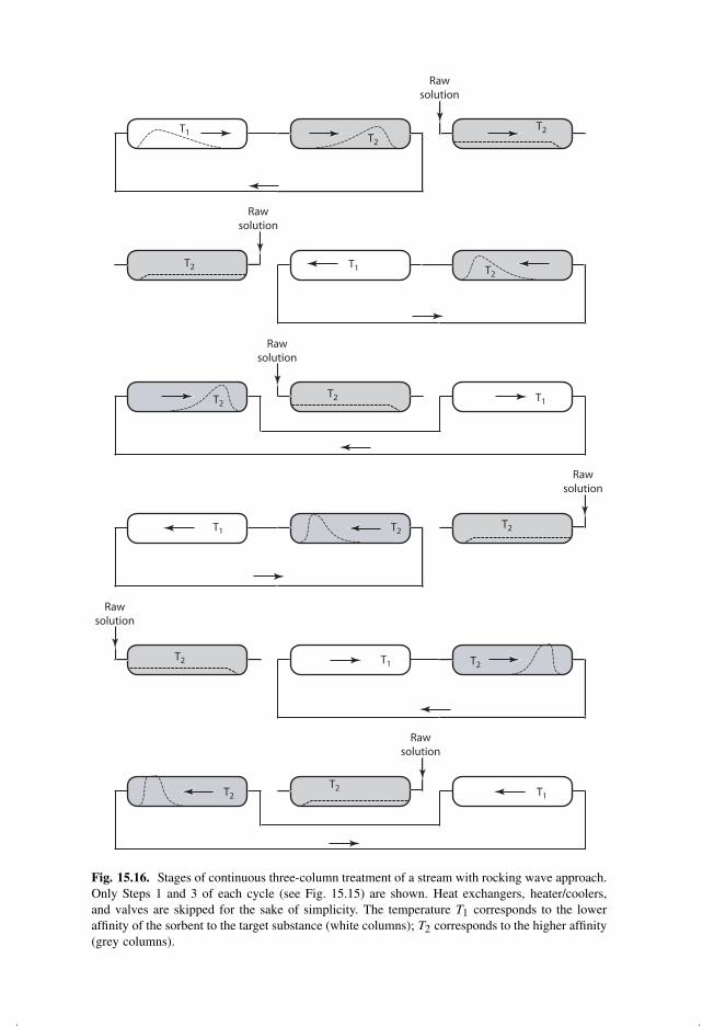
The rocking wave approach can also be used for the continuous treatment of streams.In this case, the system is supplied with the third column. The loop pumping is performedin two columns (Steps 1 and 2 of Fig. 15.15), while the third column is fed with the rawsolution at T2 (Step 3). After completing Step 2, the second column is replaced with thethird. The complete cycle of the three-column operation is shown in Fig. 15.16. As onecan see, the raw stream is continuously accommodated by the system. The concentratedproduct is collected periodically (as was said, when the highest concentration passes thecorresponding outlet).
15.7 Schemes of Dual-temperature Separation
To conclude the subject, a few words should be said about the different practical schemesof the dual-temperature method. Operations can be performed in all the different types ofion exchange reactors: stationary bed, fluidised bed, moving bed, cascade, etc. Of course,the reactors must be modified to operate in the dual-temperature mode. Panels (a–e) of
Rawsolution
T1
T1
T1
T1
T1
T1
T2
T2
T2
T2
T2
T2
T2
T2
T2
T2
T2
T2
Rawsolution
Rawsolution
Rawsolution
Rawsolution
Rawsolution
Fig. 15.16. Stages of continuous three-column treatment of a stream with rocking wave approach.Only Steps 1 and 3 of each cycle (see Fig. 15.15) are shown. Heat exchangers, heater/coolers,and valves are skipped for the sake of simplicity. The temperature T1 corresponds to the loweraffinity of the sorbent to the target substance (white columns); T2 corresponds to the higher affinity(grey columns).
336 Ion Exchange Materials: Properties and Applications
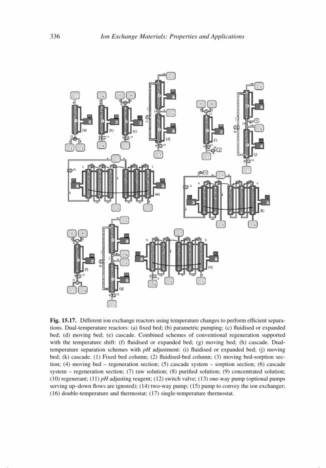
Fig. 15.17. Different ion exchange reactors using temperature changes to perform efficient separa-tions. Dual-temperature reactors: (a) fixed bed; (b) parametric pumping; (c) fluidised or expandedbed; (d) moving bed; (e) cascade. Combined schemes of conventional regeneration supportedwith the temperature shift: (f) fluidised or expanded bed; (g) moving bed; (h) cascade. Dual-temperature separation schemes with pH adjustment: (i) fluidised or expanded bed; (j) movingbed; (k) cascade. (1) Fixed bed column; (2) fluidised-bed column; (3) moving bed-sorption sec-tion; (4) moving bed – regeneration section; (5) cascade system – sorption section; (6) cascadesystem – regeneration section; (7) raw solution; (8) purified solution; (9) concentrated solution;(10) regenerant; (11) pH adjusting reagent; (12) switch valve; (13) one-way pump (optional pumpsserving up–down flows are ignored); (14) two-way pump; (15) pump to convey the ion exchanger;(16) double-temperature and thermostat; (17) single-temperature thermostat.

Dual-temperature Separation 337
Fig. 15.17 provide a collection of these schemes. In addition, Applet 16189 visualises thework of the moving bed dual-temperature reactor.
Unfortunately, the dual-temperature approach cannot be applied to every separationneed because of the low temperature sensitivity of the involved interactions. However,combining of conventional reagent regeneration with temperature shifts can bring downthe amount of regenerant required and reduce the environmental damage. Examples ofsuch systems are presented in panels (f–h) of Fig. 15.17.
An intermediate case can also be used. The regeneration is performed with the same rawsolution; however, an adjustment of its composition, synchronous with the temperaturechanges, is involved. pH is the adjusted parameter in most of the cases. Examples arepresented in panels (i–k) of Fig. 15.17.
189http://ionexchange.books.kth.se/applet16.html


![Experiment 8 Separation of proteins by ion exchange chromatography BCH 333[practical]](https://img.pdfslide.net/doc/110x75/56649db05503460f94a9e196/experiment-8-separation-of-proteins-by-ion-exchange-chromatography-bch-333practical.jpg)