Embed Size (px)
Citation preview
CHAPTER 12
Ion Exchange Purification and Separation
The main application of ion exchange materials is the separation of dissolved ions.Depending on their purpose, ion exchange separation processes can be classified asfollowing:
• Purification of a solvent is performed when the solvent is the desired product, andall the dissolved ions are considered as contaminants. The raw material is usu-ally a solution of one or more ionic substances. A typical example is the waterpurification done for electronic industry. The requirement is a zero-content of dis-solved substances, i.e. all ions present in the raw solution must be removed anddisposed.
• Purification of solution is performed when the product is a solution of certain com-position and the raw material is the same or similar solution but containing anundesirable solute. A typical example is the decontamination of an industrial wastestream by removal of one or more highly toxic substances. Another example is theremoval of toxic substances from blood during a haemodialysis treatment.
• Extraction is performed when a dissolved compound has to be extracted from asolution and the exhausted solution has no value. The typical example is the extrac-tion of gold from seawater. The product (gold) is highly valuable while the treatedwater can be disposed back to the sea without any additional care.
• The term separation is obviously applicable to all the earlier described cases. How-ever, the case of two products of interests – an ionic substance or a mixture oftarget ions and a solution or a solvent – can be named only as separation. The termseparation also includes cases where several ions of interest are obtained as differ-ent products. A typical example is obtaining different amino acids from a mixtureprepared by hydrolysis of proteins. Another example is the classical analytical ionexchange chromatography in which all compounds should be separated prior to thefinal detection procedure.
Of course, a practical treatment can combine the previously described processes. “Greyarea” cases can also be named. For example, many water purification processes can result
263
264 Ion Exchange Materials: Properties and Applications
in inorganic acids, alkalis, and salts as by-products, while originally targeting to supplyultra pure or potable water.
The purpose of the ion exchange separation process defines the selection of ion exchangematerial and method for the practical application. This selection is also affected by thescale of the separation process, economical considerations, questions of environmentalsafety, and many others. This chapter is targeted to introduce main approaches to theapplication of ion exchange materials in chemical separations.
12.1 Elution and Regeneration
When ion exchange materials are applied to extract targeted ions, these ions are trans-ferred in the exchanger phase. Clearly, substances incorporated in the ion exchangematerials have no practical interest. They have to be obtained in a useful form. In thecase of extraction of metal ions, an organic ion exchanger can be incinerated and acorresponding metal or metal oxide can be collected as the product. Incineration of achelating fibrous exchanger to obtain accumulated metallic gold [197] can be presentedas an example. However, the use of ion exchangers as disposable reactants could be aluxurious procedure because ion exchange resins, while being inexpensive, are not freeof cost. Besides, the incineration is not applicable to extraction of organic and biolog-ical substances. As a result, only few ion exchange processes end up in a furnace withmajority of such applications related to nuclear industry [557–563]. In most cases, theion exchanger is reused many times in cyclic operations.154
Let us take ion exchange removal of ion B from a solution. The ion exchange materialis in the form of ion A, i.e. the treatment is described by the ion exchange reaction
ZBRZAA + ZAB = ZARZBB + ZBA (12.1)
Reaction (12.1) is only the first stage of the operation called the sorption step. When thesorption is completed, the ion B must be harvested out of the exchanger phase througha procedure called elution.155 Then the material must be reconverted to the A form forthe next ion exchange cycle. Such re-conversion is called regeneration. Elution can beassociated with regeneration. In such a simple case, reaction (12.1) is reversed and thusharvesting of ion B and re-conversion of the exchanger to the form A proceed in onestep. Such combining is attractive due to its simplicity, but separate recovery of thesorbed ion (elution) and transfer of the material in initial ionic form (regeneration) isalso a common case. Questions of combined or separate elution/regeneration steps arediscussed in the following sections. At this moment, the reader has to note that termselution and regeneration are not synonyms. The term regeneration is solely used if thereis no interest in the utilisation of ions stripped from the exchanger during this step. Theprocess is called elution if the ion B is a species of interest, i.e. if the newly collectedsolution of B is the target of the overall process. Elution is a process opposite to sorptionin the sense of obtaining the sorbed substance. Regeneration is a process opposite to
154Cyclic operations in ion exchange treatments will be discussed in more detail in Section 12.2.155The elution can also be called desorption or recovery or stripping.
Ion Exchange Purification and Separation 265
sorption in the sense of obtaining the initial form of the ion exchanger. If more thanone product has to be separately eluted from the exchanger, several elution steps can beincluded in the process. In contrary, the one or two-step156 regeneration is performedonly once at the end of each separation cycle. Of course, a “grey area” between thesetwo terms also exists. For example, anion exchangers used in biochemical industryoften serve for simultaneous extraction of the target product and for its purification fromcoloured contaminants. Both, the product and dyes, are accumulated by the exchangerduring the sorption step. Recovery of the target product is the elution step. The dyes areremoved from the bed with a special solution. The cycle is completed with conversionof the exchanger to the desirable form, i.e. with the regeneration. The removal of dyescan be considered both as a part of the regeneration process (because it prepares theexchanger for the next cycle) or as a separate elution step. Considering the dyes removalas elution is adequate because it does not convert the exchanger to the desirable formand is not even connected to the final regeneration, i.e. if the dyes are weakly boundedto the sorbent, their removal should be done before elution of the product.
Like any chemical process, both elution and regeneration can be performed with differentefficiency. Efficiency of the elution can be characterised by the following factors:
• required amount (volume and concentration) of the eluent;
• degree of the exchanger conversion, i.e. which part of sorbed substances is recoveredfrom the material and which part of the sorbent is converted to the new ionic form;
• concentration of the effluent.
Relatively concentrated solutions are normally used to remove ions from the exchangerbecause the high concentration of the product is preferable. If the ion of interest is eluted,the eluent must not destroy the product. The eluent must not also contaminate the productor must be suitable for an easy removal. For example, solution of ammonium is oftenused to recover fragile biological substances from ion exchangers. This eluent is easilyevaporated (and recycled) from obtained concentrated solution of the product.
Requirements for the regeneration step are essentially the same with the only differencebeing that the regenerant is never in contact with the product. Of course, this is validonly for the case where regeneration is not combined with the product elution.
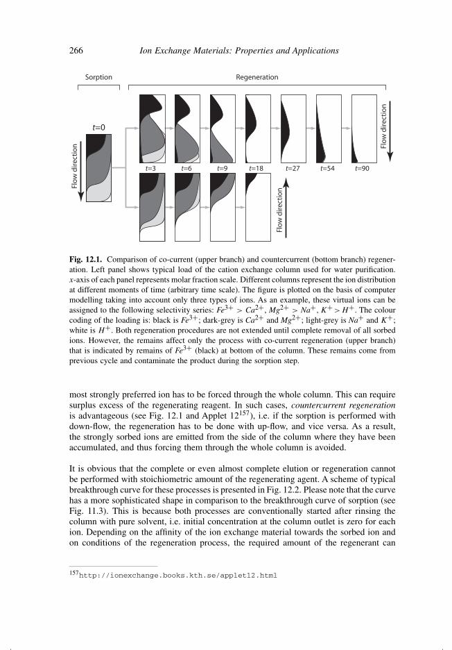
Direction of the regenerating flow can significantly affect efficiency of the column pro-cess. As an example, let us consider a water deionisation where more than one ion isremoved simultaneously, i.e. where the ion exchange column traps different ionic species.When the sorption step is performed, most of the strongly preferred ions are accumu-lated in the first layers of the column near the inlet and other ions distributed alongthe column according to the selectivity series [5] (left column in Fig. 12.1). So far asthe selectivity reverse is not a common case, the most strongly sorbed species are moststrongly retained by the exchanger during the regeneration. If the regenerant is pumpedin the same direction as the direction used at sorption (co-current regeneration), the
156Two-step regeneration is discussed in Section 12.2.
266 Ion Exchange Materials: Properties and Applications
t=3 t=6 t=9 t=18 t=27 t=54 t=90
t=0
Flo
w d
irec
tio
n Flo
w d
irec
tio
n
Flo
w d
irec
tio
n
Sorption Regeneration
Fig. 12.1. Comparison of co-current (upper branch) and countercurrent (bottom branch) regener-ation. Left panel shows typical load of the cation exchange column used for water purification.x-axis of each panel represents molar fraction scale. Different columns represent the ion distributionat different moments of time (arbitrary time scale). The figure is plotted on the basis of computermodelling taking into account only three types of ions. As an example, these virtual ions can beassigned to the following selectivity series: Fe3+ > Ca2+, Mg2+ > Na+, K+ >H+. The colourcoding of the loading is: black is Fe3+; dark-grey is Ca2+ and Mg2+; light-grey is Na+ and K+;white is H+. Both regeneration procedures are not extended until complete removal of all sorbedions. However, the remains affect only the process with co-current regeneration (upper branch)that is indicated by remains of Fe3+ (black) at bottom of the column. These remains come fromprevious cycle and contaminate the product during the sorption step.
most strongly preferred ion has to be forced through the whole column. This can requiresurplus excess of the regenerating reagent. In such cases, countercurrent regenerationis advantageous (see Fig. 12.1 and Applet 12157), i.e. if the sorption is performed withdown-flow, the regeneration has to be done with up-flow, and vice versa. As a result,the strongly sorbed ions are emitted from the side of the column where they have beenaccumulated, and thus forcing them through the whole column is avoided.
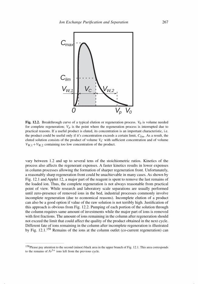
It is obvious that the complete or even almost complete elution or regeneration cannotbe performed with stoichiometric amount of the regenerating agent. A scheme of typicalbreakthrough curve for these processes is presented in Fig. 12.2. Please note that the curvehas a more sophisticated shape in comparison to the breakthrough curve of sorption (seeFig. 11.3). This is because both processes are conventionally started after rinsing thecolumn with pure solvent, i.e. initial concentration at the column outlet is zero for eachion. Depending on the affinity of the ion exchange material towards the sorbed ion andon conditions of the regeneration process, the required amount of the regenerant can
157http://ionexchange.books.kth.se/applet12.html
Ion Exchange Purification and Separation 267
Cmax
Clim
Vp0
VW,1 VC VW,2
V0
Fig. 12.2. Breakthrough curve of a typical elution or regeneration process. V0 is volume neededfor complete regeneration; Vp is the point where the regeneration process is interrupted due topractical reasons. If a useful product is eluted, its concentration is an important characteristic, i.e.the product could be useful only if it’s concentration exceeds a certain limit, Clim. As a result, theeluted solution consists of the product of volume VC with sufficient concentration and of volumeVW,1+VW,2 containing too low concentration of the product.
vary between 1.2 and up to several tens of the stoichiometric ratios. Kinetics of theprocess also affects the regenerant expenses. A faster kinetics results in lower expensesin column processes allowing the formation of sharper regeneration front. Unfortunately,a reasonably sharp regeneration front could be unachievable in many cases. As shown byFig. 12.1 and Applet 12, a major part of the reagent is spent to remove the last remains ofthe loaded ion. Thus, the complete regeneration is not always reasonable from practicalpoint of view. While research and laboratory scale separations are usually performeduntil zero-presence of removed ions in the bed, industrial processes commonly involveincomplete regeneration (due to economical reasons). Incomplete elution of a productcan also be a good option if value of the raw solution is not terribly high. Justification ofthis approach is obvious from Fig. 12.2. Pumping of each portion of the solution throughthe column requires same amount of investments while the major part of ions is removedwith first fractions. The amount of ions remaining in the column after regeneration shouldnot exceed the limit that could affect the quality of the product obtained in the next cycle.Different fate of ions remaining in the column after incomplete regeneration is illustratedby Fig. 12.1.158 Remains of the ions at the column outlet (co-current regeneration) can
158Please pay attention to the second (minor) black area in the upper branch of Fig. 12.1. This area correspondsto the remains of Fe3+ ions left from the previous cycle.
268 Ion Exchange Materials: Properties and Applications
significantly affect the product quality while remains of the ions at the column inlet(countercurrent regeneration) simply join ions brought in the next sorption step and donot harm.
One more advantage of countercurrent regeneration is the possibility to treat solu-tions containing some amount of solids. As a rule, solid-containing solutions cannotbe treated with packed bed columns because the bed works as a filtering layer. Solidsare accumulated at the inlet and block the pumping of solutions. Nevertheless, if thecontent of solids is not enough to clog the column during one cycle, they can beremoved in the countercurrent regeneration step. In contrast, the procedure with co-current regeneration accumulates solids during consequent cycles and inevitably resultsin clogging.
12.2 Cycles of Ion Exchange Separation
Columns loaded with ion exchangers are used repeatedly in most of the applications.159
Actual operation cycle could be specific for each particular case; however, a number ofprinciples can be recognised. When designing cyclic operations, efficient use of the bedis one of the keys to optimise the process. To achieve an efficient separation, the systemand conditions with high selectivity to the targeted ions are preferred.
In a few cases, the selectivity of the ion exchanger can be reversed in such a way thatthe equilibrium is favourable in both the sorption and the regeneration steps. A classicalexample is water softening with a strong cation exchanger where small quantities ofCa2+, Mg2+, and other polyvalent cations are replaced with Na+. In the sorption step adilute solution is treated. The target ions are selectively sorbed due to the preference ofion exchangers to multivalent ions, i.e.
˜̃KMe
Na =[Me2+
][Na+]2
[Na+
]2 [Me2+]> 1 (dilute solutions) (12.2)
The selectivity is reversed in highly concentrated media
˜̃KNa
Me =[Na+
]2 [Me2+][Me2+
][Na+]2
> 1 (concentrated solutions) (12.3)
and Na+ efficiently replaces the polyvalent ions. Thus, the ion exchanger can beregenerated with only little more than the stoichiometric amount of the concentratedsodium-containing solution. Much of the success of ion exchange in water softening is
159Most of the approaches which are described later for cyclic column operations are also applicable to batchion exchange separation techniques. However, due to essentially higher efficiency, column processes are mainlydiscussed. This must not harm the overall picture because the batch processes are much simpler then columnoperations.
Ion Exchange Purification and Separation 269
Purifiedsolvent
Elut
ion
and
rege
nera
tion
Sorp
tion
Treatedsolution
Regenerant(Eluent)
Concentratedions
Purifiedsolvent
Elut
ion
Rege
nera
tion
Sorp
tion
Treatedsolution
Eluent Regenerant
Concentratedions
Regenerationwastes
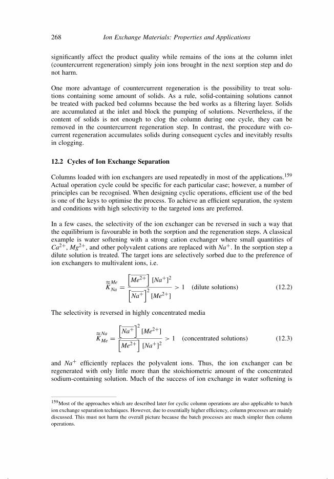
Fig. 12.3. Simplest cycles of ion exchange separation: two-step process combining elution andregeneration (left) and three-step process with separate elution and regeneration procedures(right).
due to this fortunate coincidence [5]. This effect allows designing a simplest cycle ofion exchange separation which is illustrated by left panel of Fig. 12.3.
As a rule, however, a high selectivity towards the sorbed ion results in unfavourableequilibrium and a non-sharpening front at the regeneration step and, hence, toundesirable expenses of the regenerating solution. In many cases, only a mod-erate selectivity of the ion exchanger towards targeted species is the best com-promise [5]. Nevertheless, highly selective ion exchangers are required for theefficient removal of small quantities of one species from a surplus excess of com-peting counterions. Straightforward regeneration of such materials usually requiresexcessive amounts of reagents. Performing the regeneration in two steps withfavourable equilibria could be a better choice. For example, one-step re-conversionof iminodiacetic chelating groups from the Cu2+ or Ni2+ form to Na+ form
N
CH2
CH2
COO− +Na
COO− +Na
Cu2+N
CH2
CH2
COO−
COO−Cu2+ + 2Na+
+ (12.4)160
is completely impractical because of the high selectivity of the material towards the tran-sition metal ions (αCu
Na ≈ 2900). These metals, however, are easily exchanged to hydrogen
160Equations of this section do not include a bar to denote phase of the ion exchanger. The phase indicationis omitted because the same reactions also take place at complexing in homogeneous solutions.
270 Ion Exchange Materials: Properties and Applications
ions when treated with a strong acid because H+ protonates the nitrogen donor atomdestroying the chelate structure:
NH+CH2
CH2
COO− +H
COO− +H
Cu2+N
CH2
CH2
COO−
COO−Cu2+ + 3H+ + (12.5)
Transfer of charge-compensating co-ions between phases is not shown in Eqs (12.5)and (12.6) for the sake of simplicity. The obtained H+ form is not suitable for sorptionof transitional metal ions. However, it is easily converted to Na+ form by treatmentwith NaOH
N
CH2
CH2
COO− +Na
COO− +Na
NH+CH2
CH2
COO− +H
COO− +H
+ 2Na+ + 3OH−+ 3H2O (12.6)
Neutralisation of H+ by OH− makes the overall equilibrium highly favourable for theconversion (12.6). This three-step separation cycle is illustrated by the right panel ofFig. 12.3.
Washing steps are often introduced between operations. For example, a washing is nec-essary between the elution and regeneration steps in the previously described cycle toavoid the neutralisation reaction between the alkali solution and remains of the acid con-tained in the bed. The washing also reduces acidity of the exchanger’s internal solutioncausing deprotonation
NH+CH2
CH2
COO− +H
COO− +H
N
CH2
CH2
COO− +H
COO− +H
H++ (12.7)
however, conditions of the washing step are not alkaline enough to complete this reaction.
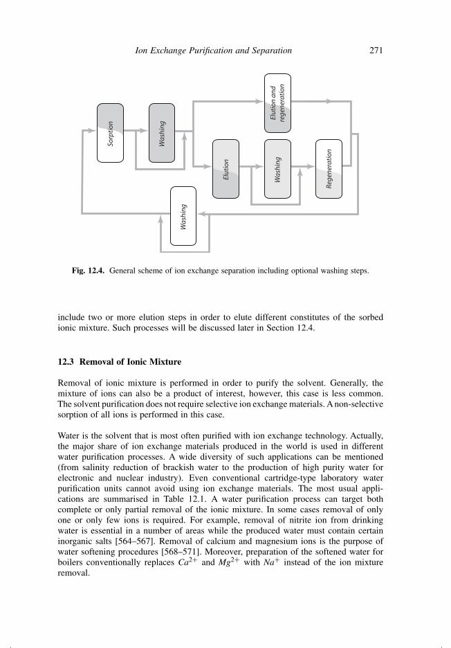
The general scheme of the ion exchange separation cycle is presented in Fig. 12.4. Itshows that all cyclic ion exchange processes include sorption, elution, and regenera-tion stages. As described earlier, in a number of cases elution and regeneration could beintegrated in one step.161 Washing steps (if needed) can be incomplete. A rinsing or evena simple displacement of solution by water is enough in many cases. Some processes
161Both names are used for the combined elution/regeneration step. The choice of notation could be due tothe main purpose of the operation. If extraction of the ion is performed, the step is referred as elution. If theprocess is purification of the solution, purpose of the step is preparation for the next treatment cycle and thusthe step is referred as regeneration.
Ion Exchange Purification and Separation 271
Sorp
tion
Was
hing
Elut
ion
and
rege
nera
tion
Elut
ion
Was
hing
Rege
nera
tion
Was
hing
Fig. 12.4. General scheme of ion exchange separation including optional washing steps.
include two or more elution steps in order to elute different constitutes of the sorbedionic mixture. Such processes will be discussed later in Section 12.4.
12.3 Removal of Ionic Mixture
Removal of ionic mixture is performed in order to purify the solvent. Generally, themixture of ions can also be a product of interest, however, this case is less common.The solvent purification does not require selective ion exchange materials. A non-selectivesorption of all ions is performed in this case.
Water is the solvent that is most often purified with ion exchange technology. Actually,the major share of ion exchange materials produced in the world is used in differentwater purification processes. A wide diversity of such applications can be mentioned(from salinity reduction of brackish water to the production of high purity water forelectronic and nuclear industry). Even conventional cartridge-type laboratory waterpurification units cannot avoid using ion exchange materials. The most usual appli-cations are summarised in Table 12.1. A water purification process can target bothcomplete or only partial removal of the ionic mixture. In some cases removal of onlyone or only few ions is required. For example, removal of nitrite ion from drinkingwater is essential in a number of areas while the produced water must contain certaininorganic salts [564–567]. Removal of calcium and magnesium ions is the purpose ofwater softening procedures [568–571]. Moreover, preparation of the softened water forboilers conventionally replaces Ca2+ and Mg2+ with Na+ instead of the ion mixtureremoval.
272 Ion Exchange Materials: Properties and Applications
Table 12.1. Main applications of ion exchange materials in waterdeionisation processes.
Process Purpose
Brackish water desalination Production of drinking waterWater softening Water for boilersPreparation of high purity water Nuclear industry
ElectronicsChemical industryLaboratory use
Typical schemes of ionic mixture removal are presented in Fig. 12.3 (Section 12.2) andconsist of the following operations:
• Sorption is performed until the maximum allowed concentration in the effluent(Clim, see Fig. 11.3). Complete loading of the exchanger is useless because atV >Vlim the effluent does not fit to imposed requirements for the purified solventor solution.
• The regeneration stage can be combined with elution because, in most of thecases, the obtained ionic mixture is considered to be a waste. Separate elution andregeneration steps could be applied if this allows to improve efficiency of the ionicform re-conversion. More complicated elution/regeneration schemes could also beused if recuperation of some ions is required.
• The rinsing (washing) between sorption and regeneration is optional. It is notperformed in most of the cases unless some ions are recuperated.
• The rinsing after regeneration is obligatory. The bed must not contain any ions priorto the sorption stage because these ions can contaminate the product. Besides waterpurification, removal of ions with ion exchange materials is used for purification ofnon-ionic species, for example, for demineralisation in dairy [572,573].
The earlier described separation cycle can also be used for removal of one or moreundesirable ions from an ionic mixture. In this case, the ion exchange material must behighly selective for the ion (or group of ions) targeted for removal (in comparison withions remaining in the solution).
Similar techniques are also used for:
• neutralisation of acidic or alkaline solutions without reduction of the total ioniccontent; for example,
R−Na+ + H+Cl− = R−H+ + Na+Cl− (12.8)
• conversion of salts to acids (exploiting reactions opposite to (12.8)) and salts toalkalis;
• conversion of one salt to another one (that is widely exploited in so called ionexchange synthesis [112]).
Ion Exchange Purification and Separation 273
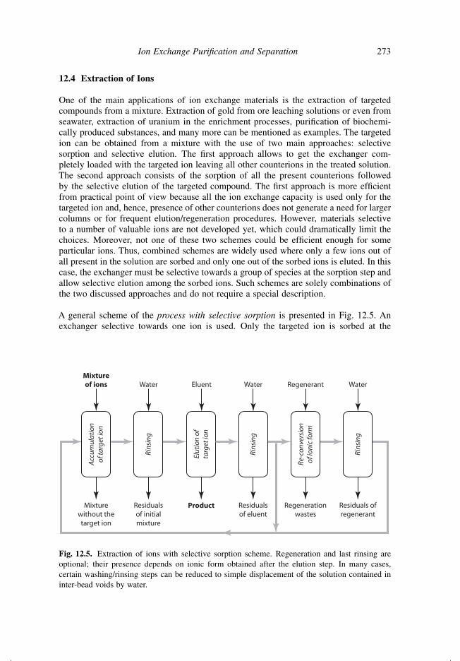
12.4 Extraction of Ions
One of the main applications of ion exchange materials is the extraction of targetedcompounds from a mixture. Extraction of gold from ore leaching solutions or even fromseawater, extraction of uranium in the enrichment processes, purification of biochemi-cally produced substances, and many more can be mentioned as examples. The targetedion can be obtained from a mixture with the use of two main approaches: selectivesorption and selective elution. The first approach allows to get the exchanger com-pletely loaded with the targeted ion leaving all other counterions in the treated solution.The second approach consists of the sorption of all the present counterions followedby the selective elution of the targeted compound. The first approach is more efficientfrom practical point of view because all the ion exchange capacity is used only for thetargeted ion and, hence, presence of other counterions does not generate a need for largercolumns or for frequent elution/regeneration procedures. However, materials selectiveto a number of valuable ions are not developed yet, which could dramatically limit thechoices. Moreover, not one of these two schemes could be efficient enough for someparticular ions. Thus, combined schemes are widely used where only a few ions out ofall present in the solution are sorbed and only one out of the sorbed ions is eluted. In thiscase, the exchanger must be selective towards a group of species at the sorption step andallow selective elution among the sorbed ions. Such schemes are solely combinations ofthe two discussed approaches and do not require a special description.
A general scheme of the process with selective sorption is presented in Fig. 12.5. Anexchanger selective towards one ion is used. Only the targeted ion is sorbed at the
Mixturewithout thetarget ion
Rins
ing
Elut
ion
ofta
rget
ion
Acc
umul
atio
nof
targ
et io
n
Mixtureof ions Water Eluent
Residualsof initialmixture
Product
Rins
ing
Water
Residualsof eluent
Re-c
onve
rsio
nof
ioni
c fo
rm
Regenerant
Regenerationwastes
Rins
ing
Water
Residuals ofregenerant
Fig. 12.5. Extraction of ions with selective sorption scheme. Regeneration and last rinsing areoptional; their presence depends on ionic form obtained after the elution step. In many cases,certain washing/rinsing steps can be reduced to simple displacement of the solution contained ininter-bead voids by water.
274 Ion Exchange Materials: Properties and Applications
sorption stage. All other ions remain in the solution. Sorption can be performed intwo ways:
• If the raw solution is valuable, the sorption is conducted until maximumallowed concentration of the effluent is reached (see Fig. 11.3). The maxi-mum allowed concentration of the effluent is related to the maximum allowedloss of the product.
• If the raw solution is freely available, complete or almost complete loading of thebed is performed. The concentration in the effluent is not limited but probablycontrolled to monitor the sorption process.
One can wonder how a solution of the valuable targeted ion could be freely available.A typical example of such application is the extraction of precious metals from seawater.The seawater contains around 0.5 µg/m3 of dissolved gold [574,575] with 1.5 µg/m3 ormore in special locations [575]. Since the value of seawater is zero, sorption of the goldinvolves only the cost of pumping.
In most of the cases, the elution stage of the process with selective sorption is separatedfrom regeneration because requirement for the product purity limits the choice of suitableeluents. For example, let us discuss the extraction of an α-amino acid from a biochemicalmixture with the use of a sulphonic cation exchange resin. In acidic environment, aminoacids are cations H3N
+− R′–COOH and thus can be sorbed through conventional cationexchange reaction. At neutral or close to neutral pH of solutions, amino acids are zwit-terions which can be presented in a simplified way as H3N
+ −R′–COO−. The overallcharge of such species is neutral. An ion exchange reaction on metal forms of cationexchangers does not take place
R−+Na + H3N+ − R′−COO− �= (12.9)
Acidification of the raw solution to convert the amino acid to cationic form prior to theion exchange treatment could be undesirable. Fortunately, the stoichiometric reaction
R−+H + H3N+ − R′−COO− = R−H3N+ − R′−COOH (12.10)
can be efficiently exploited if the hydrogen form of the material is used.
Reaction (12.10) is similar to reaction (12.11) that takes place when a solution ofzwitterions is acidified and thus the zwitterions are converted to cations:
H3N+ − R′−COO− + H+ = H3N
+ − R′−COOH (12.11)
Indeed, while entering the ion exchanger phase zwitterions change the environment fromneutral to highly acidic because the hydrogen ions are kept inside the material (due tothe electroneutrality requirement).
Ion Exchange Purification and Separation 275
A combined elution/regeneration process with an acidic solution would contaminate theproduct with anions:
R−H3N+ − R′−COOH + H+ + Y− = R−+H + Y−+H3N − R′−COOH (12.12)
i.e. salt would be produced instead of pure amino acid. Moreover, the necessary excess ofthe eluting reagent could be present in the product as an impurity. Solution of ammoniumis applied for the elution instead:
R−H3N+ − R′−COOH + NH+4 + OH− = R−+NH4 + H3N
+ − R′−COO− + H2O
(12.13)
As was described earlier, the ammonium elution is common in separation processesbecause remains of this substance can be easily evaporated from the product. The materialis transformed to the ammonium form and has to be regenerated:
R−+NH4 + H+ = R−+H + NH+4 (12.14)
Different steps of the process with selective sorption are usually separated by rinsing orwashing steps. The rinsing (washing) after the sorption is obligatory because it providespurity to the product. The rinsing (or, at least, displacement with water) between theelution and regeneration is obligatory if an alkali is used for elution and an acid forregeneration or vice versa. It has to be done in order to avoid a rapid heat-producingreaction inside the exchanger phase that can evaluate vapours destroying the material,mixing the bed, etc. The rinsing after regeneration is optional and depends on the valueof the raw solution.
In contrary to the selective sorption scheme, the mixture of ions is sorbed in the selectiveelution process. The elution is performed in two, three, or more steps in order to obtainpure fraction of the targeted ion(s). Let us consider a model example of CrO−
4 extractionfrom a mixture with SO2−
4 and Cl−. The selectivity series for most of the general-purposestrong anion exchange resins (for example, of a styrene–divinylbenzene resin bearingquaternary amines) is
SO2−4 > CrO−
4 > Cl− (12.15)
The non-selective sorption of the whole ionic mixture is performed. A weak eluentremoves only chlorine ion. Application of a stronger eluent extracts the targeted CrO−
4out of the column. The sulphate ion can be removed at regeneration with a strong reagent.
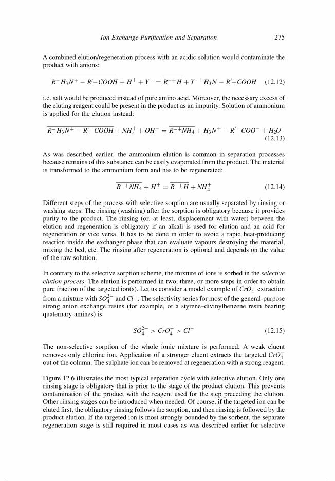
Figure 12.6 illustrates the most typical separation cycle with selective elution. Only onerinsing stage is obligatory that is prior to the stage of the product elution. This preventscontamination of the product with the reagent used for the step preceding the elution.Other rinsing stages can be introduced when needed. Of course, if the targeted ion can beeluted first, the obligatory rinsing follows the sorption, and then rinsing is followed by theproduct elution. If the targeted ion is most strongly bounded by the sorbent, the separateregeneration stage is still required in most cases as was described earlier for selective
276 Ion Exchange Materials: Properties and Applications
Purifiedsolvent
Rem
oval
of
wea
kly
boun
d io
ns
Rins
ing
Sorp
tion
of
ioni
c m
ixtu
re
Mixtureof ions
Firsteluent Water
Mixture of ionsweakly interactingwith the exchanger
Residual offirst eluent
Elut
ion
of
targ
et i
on
Secondeluent
Product
Rem
oval
of
stro
ngly
boun
d io
nsan
d re
gene
rati
on
Regenerant
Regenerationwastes
Rins
ing
Water
Residuals ofregenerant
Fig. 12.6. Extraction of ions with selective elution scheme. Only obligatory steps are shown.
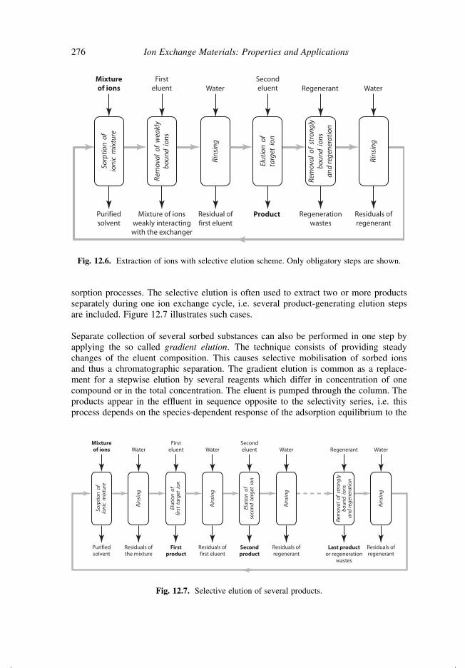
sorption processes. The selective elution is often used to extract two or more productsseparately during one ion exchange cycle, i.e. several product-generating elution stepsare included. Figure 12.7 illustrates such cases.
Separate collection of several sorbed substances can also be performed in one step byapplying the so called gradient elution. The technique consists of providing steadychanges of the eluent composition. This causes selective mobilisation of sorbed ionsand thus a chromatographic separation. The gradient elution is common as a replace-ment for a stepwise elution by several reagents which differ in concentration of onecompound or in the total concentration. The eluent is pumped through the column. Theproducts appear in the effluent in sequence opposite to the selectivity series, i.e. thisprocess depends on the species-dependent response of the adsorption equilibrium to the
Purifiedsolvent
Rins
ing
Elut
ion
of
first
tar
get
ion
Sorp
tion
of
ioni
c m
ixtu
re
Mixtureof ions Water
Firsteluent
Residuals ofthe mixture
Firstproduct
Rins
ing
Water
Residuals offirst eluent
Elut
ion
of
seco
nd t
arge
t io
n
Secondeluent
Secondproduct
Rins
ing
Water
Residuals ofregenerant
Rem
oval
of
stro
ngly
boun
d io
nsan
d re
gene
rati
on
Regenerant
Last productor regeneration
wastes
Rins
ing
Water
Residuals ofregenerant
Fig. 12.7. Selective elution of several products.
Ion Exchange Purification and Separation 277
eluent concentration. It is perhaps the most widely used operating mode for proteinfractionation. A common example would be the addition of increasing amounts of saltin the feed of the ion exchange column [284,576–578]. One has to note that, like anychromatographic process, gradient elution is more reagent- and time-consuming in com-parison to multi-step separations while allowing simplicity of the operation. Thus, it ismore common in small-scale separations.
12.5 Multistep Deionisation
As was described earlier, ion exchange is widely used for the complete removal ofelectrolytes from solutions. The process is called deionisation or demineralisation or,in case of water treatment, water purification. Complete removal of electrolytes, unlessthey are acids or bases, requires the treatment with both cation and anion exchangeprocesses. Let us consider the simplest example first. The solution contains only dissolvedNaCl. H+ form of cation exchanger is used to replace sodium with hydrogen:
RSO−+3 H + Na+ + Cl− = RSO−+
3 Na + H+ + Cl− (12.16)
The hydrochloric acid produced is treated by OH− form of anion exchanger
RN+(CH3)3OH− + Cl− + H+ = RN+(CH3)3Cl− + H2O (12.17)
No ions (exclude H+ and OH− from the water dissociation) are present in the product.
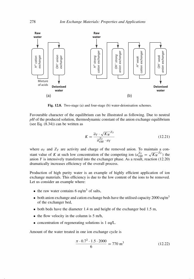
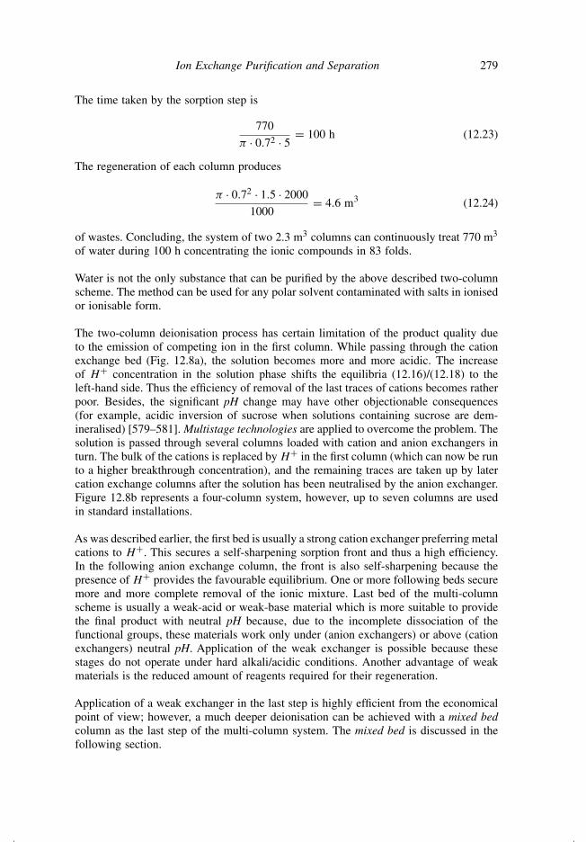
The general scheme of such two-stage deionisation process is presented in Fig. 12.8a. Thesolution is first passed through the cation exchange bed in H+ form and then through ananion exchange bed in OH− form. All cations (A1, A2, . . .) are removed in the first bed
A1 + A2 + · · · + H+ → A1 + A2 + · · · + H+ (12.18)
the anions (Y1, Y2, . . .) are removed in the second bed
Y1 + Y2 + · · · + OH− → Y1 + Y2 + · · · + OH− (12.19)
Equations (12.18) and (12.19) are general cases of (12.16) and (12.17).
In most of the cases, the cation exchanger treatment is performed first as illustratedby Fig. 12.8a. It provides a self-sharpening front with the use of most of the cationexchangers (for example, with styrene–divinylbenzene resins bearing −SO3H groups).The front in the following anion exchange column is self-sharpening because hydroxideions released by the anion exchanger immediately react with H+ (released from thecation exchanger in the previous stage)
H+ + OH− = H2O (12.20)
278 Ion Exchange Materials: Properties and Applications
Mixtureof acids
OH
− an
ion
exch
ange
r
H+
cati
onex
chan
ger
Rawwater
(a) (b)
Deionisedwater
OH
− str
ong
anio
n e
xcha
nger
H+
stro
ngca
tion
exc
hang
er
Rawwater
H+ w
eak
cati
on e
xcha
nger
OH
− w
eak
anio
n e
xcha
nger
Deionisedwater
Fig. 12.8. Two-stage (a) and four-stage (b) water-deionisation schemes.
Favourable character of the equilibrium can be illustrated as following. Due to neutralpH of the produced solution, thermodynamic constant of the anion exchange equilibrium(see Eq. (8.34)) can be written as
K = aY · √KW
ZY
aZY
OH · aY
(12.21)
where aY and ZY are activity and charge of the removed anion. To maintain a con-stant value of K at such low concentration of the competing ion (aZY
OH = √KW
ZY ) theanion Y is intensively transferred into the exchanger phase. As a result, reaction (12.20)dramatically increases efficiency of the overall process.
Production of high purity water is an example of highly efficient application of ionexchange materials. This efficiency is due to the low content of the ions to be removed.Let us consider an example where:
• the raw water contains 6 eq/m3 of salts,
• both anion exchange and cation exchange beds have the utilised capacity 2000 eq/m3
of the exchanger bed,
• both beds have the diameter 1.4 m and height of the exchanger bed 1.5 m,
• the flow velocity in the column is 5 m/h,
• concentration of regenerating solutions is 1 eq/L.
Amount of the water treated in one ion exchange cycle is
π · 0.72 · 1.5 · 2000
6= 770 m3 (12.22)
Ion Exchange Purification and Separation 279
The time taken by the sorption step is
770
π · 0.72 · 5= 100 h (12.23)
The regeneration of each column produces
π · 0.72 · 1.5 · 2000
1000= 4.6 m3 (12.24)
of wastes. Concluding, the system of two 2.3 m3 columns can continuously treat 770 m3
of water during 100 h concentrating the ionic compounds in 83 folds.
Water is not the only substance that can be purified by the above described two-columnscheme. The method can be used for any polar solvent contaminated with salts in ionisedor ionisable form.
The two-column deionisation process has certain limitation of the product quality dueto the emission of competing ion in the first column. While passing through the cationexchange bed (Fig. 12.8a), the solution becomes more and more acidic. The increaseof H+ concentration in the solution phase shifts the equilibria (12.16)/(12.18) to theleft-hand side. Thus the efficiency of removal of the last traces of cations becomes ratherpoor. Besides, the significant pH change may have other objectionable consequences(for example, acidic inversion of sucrose when solutions containing sucrose are dem-ineralised) [579–581]. Multistage technologies are applied to overcome the problem. Thesolution is passed through several columns loaded with cation and anion exchangers inturn. The bulk of the cations is replaced by H+ in the first column (which can now be runto a higher breakthrough concentration), and the remaining traces are taken up by latercation exchange columns after the solution has been neutralised by the anion exchanger.Figure 12.8b represents a four-column system, however, up to seven columns are usedin standard installations.
As was described earlier, the first bed is usually a strong cation exchanger preferring metalcations to H+. This secures a self-sharpening sorption front and thus a high efficiency.In the following anion exchange column, the front is also self-sharpening because thepresence of H+ provides the favourable equilibrium. One or more following beds securemore and more complete removal of the ionic mixture. Last bed of the multi-columnscheme is usually a weak-acid or weak-base material which is more suitable to providethe final product with neutral pH because, due to the incomplete dissociation of thefunctional groups, these materials work only under (anion exchangers) or above (cationexchangers) neutral pH. Application of the weak exchanger is possible because thesestages do not operate under hard alkali/acidic conditions. Another advantage of weakmaterials is the reduced amount of reagents required for their regeneration.
Application of a weak exchanger in the last step is highly efficient from the economicalpoint of view; however, a much deeper deionisation can be achieved with a mixed bedcolumn as the last step of the multi-column system. The mixed bed is discussed in thefollowing section.
280 Ion Exchange Materials: Properties and Applications
12.6 Mixed Bed Deionisation
The deepest degree of deionisation can be obtained with a single column containing anintimate mixture of cation and anion exchanger beads, called the mixed bed [5,582].The technique is widely used in the preparation of highly pure water.162 As a result ofthe close distances between beads belonging to two types of ion exchangers, the cationand anion exchange reactions take place in close proximity to each other. The overallreaction can be written as
R− +H + R+ −OH + A+ + Y− = R−+A + R+ −Y + H2O (12.25)
where R− and R+ represent two different ion exchange materials. The disappearanceof H+ and OH− ions due to the water formation shifts the equilibrium to the right-hand side. All interactions described by reaction (12.25) take place locally; the solutionremains neutral. This secures a highly favourable equilibria of both processes involvedand thus almost a perfect utilisation of the capacity and the highest degree of deionisation.Mixed bed provides ultra-pure water which is used in many industries with the majorusers being in nuclear power and electronics.
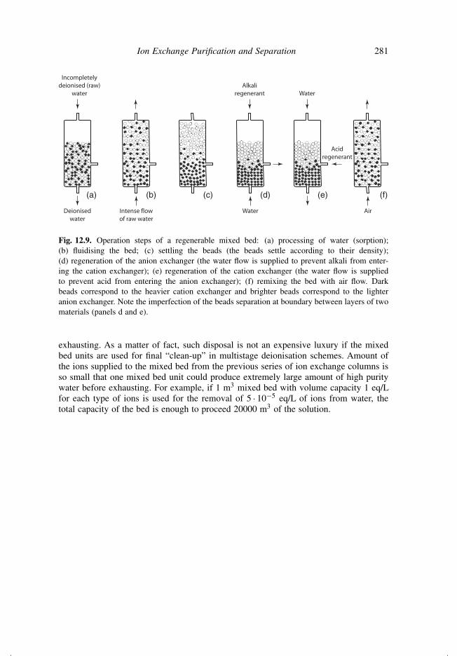
Significant drawback in the practical use of mixed bed systems is the difficulty of regen-eration. No perfect solution has been found yet. In most of the cases two ion exchangersare separated, individually regenerated, and remixed again. The separation of two mate-rials can be performed by pumping water upward through the column [5,582]. Aftercutting off the water flow, the heavier cation exchanger settles below the lighter anionexchanger (density of conventionally used cation exchangers is ≈1.26; density of theanion exchangers is ≈1.07). A typical operation for the regenerable mixed bed column ispresented in Fig. 12.9 [5]. After the sorption step the bed is fluidised with water. When thewater flow is cut off the anion exchange resin settles on top of the cation exchange resin.The two layers are regenerated in sequence. First, alkaline solution is fed downward andremoved through an outlet positioned at the interface of the two materials. After a rinseremoving the alkaline solution, the acidic regeneration is performed by pumping theacid at the interface and collecting the effluent at the bottom of the column. The residualacid is rinsed out and finally the bed is remixed (e.g. with air agitation). Feeding theregenerating solutions is accompanied by water pumping through “idle” layers. This isdone to prevent the regenerants from entering the “wrong” ion exchangers.
Unfortunately, the complete separation is difficult to achieve. Remains of the foreignexchangers, undesirably involved in the separate regeneration procedures affect qualityof the water produced in the following cycle. Thus, the main problem of the mixed bedreuse is mechanical in origin and arises from the need to separate the exchangers forregeneration. Cross-contamination of the individual materials with the wrong regenerantis a common outcome of incomplete separation of the cation and anion exchangers priorto the regeneration stage [583]. As a result, non-regenerable mixed bed units are used incases of high demand for the product quality. The mixture of exchangers is disposed after
162Deionisation of water is the most common but only one of the many applications of the mixed bed approach.The same ideas and principles are successfully used in other separation applications as well as in analyticaltechniques.
Ion Exchange Purification and Separation 281
Alkaliregenerant
Water
Acidregenerant
Water
Air
Incompletelydeionised (raw)
water
Deionisedwater
Intense flowof raw water
(a) (b) (c) (d) (e) (f)
Fig. 12.9. Operation steps of a regenerable mixed bed: (a) processing of water (sorption);(b) fluidising the bed; (c) settling the beads (the beads settle according to their density);(d) regeneration of the anion exchanger (the water flow is supplied to prevent alkali from enter-ing the cation exchanger); (e) regeneration of the cation exchanger (the water flow is suppliedto prevent acid from entering the anion exchanger); (f) remixing the bed with air flow. Darkbeads correspond to the heavier cation exchanger and brighter beads correspond to the lighteranion exchanger. Note the imperfection of the beads separation at boundary between layers of twomaterials (panels d and e).
exhausting. As a matter of fact, such disposal is not an expensive luxury if the mixedbed units are used for final “clean-up” in multistage deionisation schemes. Amount ofthe ions supplied to the mixed bed from the previous series of ion exchange columns isso small that one mixed bed unit could produce extremely large amount of high puritywater before exhausting. For example, if 1 m3 mixed bed with volume capacity 1 eq/Lfor each type of ions is used for the removal of 5 · 10−5 eq/L of ions from water, thetotal capacity of the bed is enough to proceed 20000 m3 of the solution.