Embed Size (px)
Citation preview
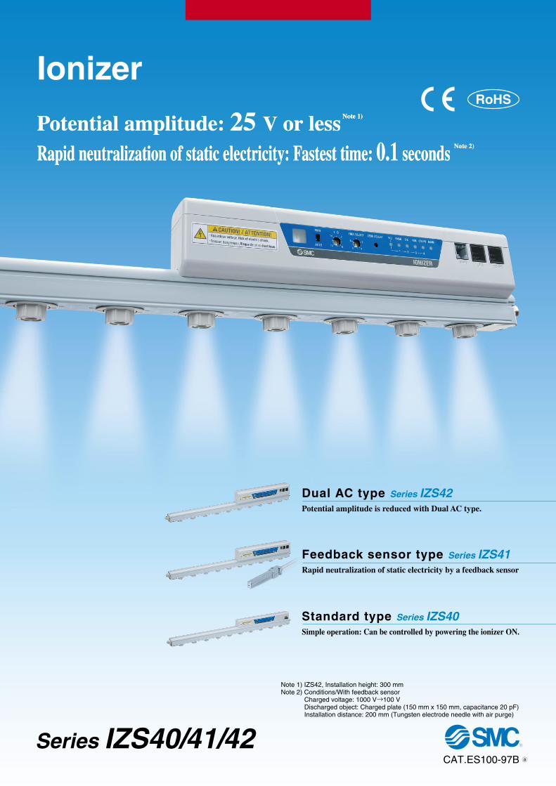
Potential amplitude: 25 V or less Note 1)
Rapid neutralization of static electricity: Fastest time: 0.1 seconds Note 2)
Potential amplitude: 25 V or less Note 1)
Rapid neutralization of static electricity: Fastest time: 0.1 seconds Note 2)
Potential amplitude is reduced with Dual AC type.
Dual AC type Series IZS42
Rapid neutralization of static electricity by a feedback sensor
Feedback sensor type Series IZS41
Simple operation: Can be controlled by powering the ionizer ON.
Standard type Series IZS40
Note 1) IZS42, Installation height: 300 mmNote 2) Conditions/With feedback sensor Charged voltage: 1000 V→100 V Discharged object: Charged plate (150 mm x 150 mm, capacitance 20 pF) Installation distance: 200 mm (Tungsten electrode needle with air purge)
Ionizer
CAT.ES100-97B
Series IZS40/41/42
RoHS
a
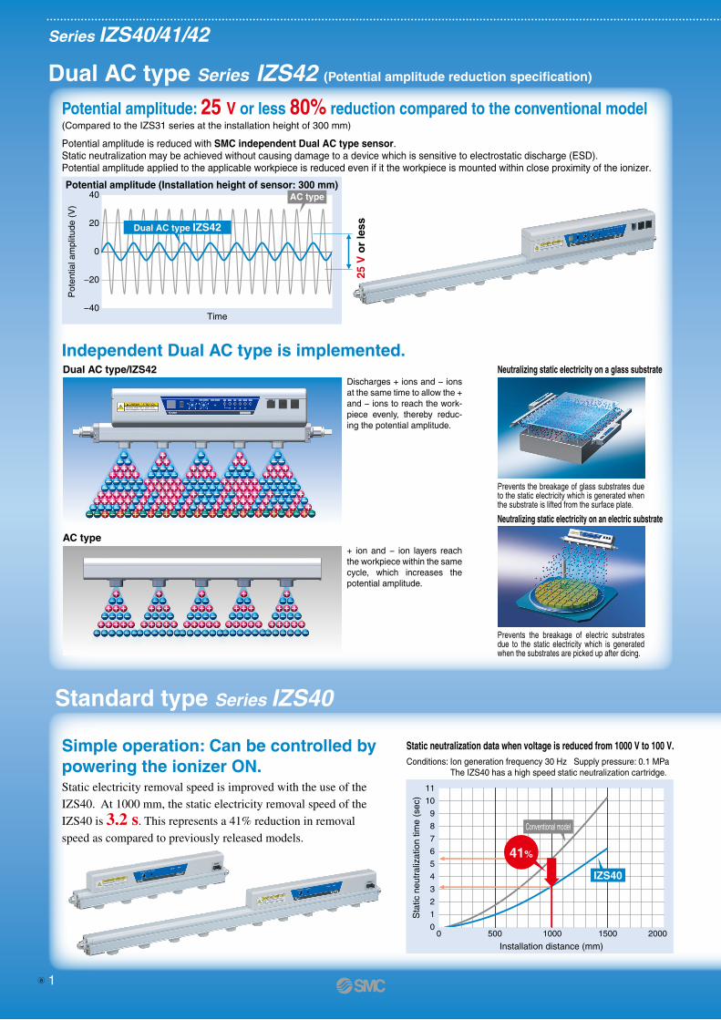
Potential amplitude is reduced with SMC independent Dual AC type sensor. Static neutralization may be achieved without causing damage to a device which is sensitive to electrostatic discharge (ESD).Potential amplitude applied to the applicable workpiece is reduced even if it the workpiece is mounted within close proximity of the ionizer.
Potential amplitude: 25 V or less 80% reduction compared to the conventional model(Compared to the IZS31 series at the installation height of 300 mm)
Simple operation: Can be controlled by powering the ionizer ON.
Independent Dual AC type is implemented. Dual AC type/IZS42
Discharges + ions and − ions at the same time to allow the + and − ions to reach the work-piece evenly, thereby reduc-ing the potential amplitude.
AC type+ ion and − ion layers reach the workpiece within the same cycle, which increases the potential amplitude.
Conditions: Ion generation frequency 30 Hz Supply pressure: 0.1 MPa The IZS40 has a high speed static neutralization cartridge.
Static electricity removal speed is improved with the use of the
IZS40. At 1000 mm, the static electricity removal speed of the
IZS40 is 3.2 s. This represents a 41% reduction in removal
speed as compared to previously released models.
Neutralizing static electricity on a glass substrate
Neutralizing static electricity on an electric substrate
Dual AC type Series IZS42 (Potential amplitude reduction specification)
Standard type Series IZS40
Series IZS40/41/42
0
11
10
9
8
7
6
5
4
3
2
1
0 500 1000 1500 2000
Installation distance (mm)
Sta
tic n
eutr
aliz
atio
n tim
e (s
ec)
Static neutralization data when voltage is reduced from 1000 V to 100 V.
IZS40
41%
Prevents the breakage of glass substrates due to the static electricity which is generated when the substrate is lifted from the surface plate.
Prevents the breakage of electric substrates due to the static electricity which is generated when the substrates are picked up after dicing.
Ionizer
e-con connector is used.
Suitable for static neutralization of resin and rubberpieces (small parts).
e-con connector
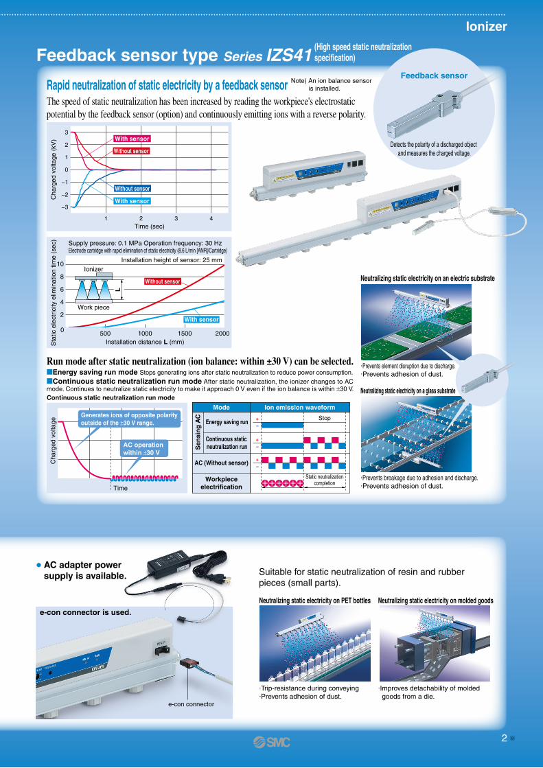
The speed of static neutralization has been increased by reading the workpiece's electrostaticpotential by the feedback sensor (option) and continuously emitting ions with a reverse polarity.
Run mode after static neutralization (ion balance: within ±30 V) can be selected.Energy saving run mode Stops generating ions after static neutralization to reduce power consumption. Continuous static neutralization run mode After static neutralization, the ionizer changes to AC mode. Continues to neutralize static electricity to make it approach 0 V even if the ion balance is within ±30 V.
Neutralizing static electricity on an electric substrate
·Prevents element disruption due to discharge.·Prevents adhesion of dust.
Neutralizing static electricity on PET bottles
·Trip-resistance during conveying·Prevents adhesion of dust.
Neutralizing static electricity on molded goods
·Improves detachability of molded goods from a die.
Neutralizing static electricity on a glass substrate
·Prevents breakage due to adhesion and discharge.·Prevents adhesion of dust.
Rapid neutralization of static electricity by a feedback sensor
Feedback sensor type Series IZS41
Feedback sensor
Detects the polarity of a discharged object and measures the charged voltage.
−+
−+
Stop
Ion emission waveformMode
Energy saving run
Continuous static neutralization run
−+
AC (Without sensor)
Workpieceelectrification
Static neutralizationcompletion
Time
Cha
rged
vol
tage
Generates ions of opposite polarity outside of the ±30 V range.
AC operation within ±30 V
3
2
1
0
−1
−2
−3
1 2 3 4Time (sec)
Cha
rged
vol
tage
(kV
) With sensor
Without sensor
With sensor
Without sensor
Continuous static neutralization run mode
Supply pressure: 0.1 MPa Operation frequency: 30 HzElectrode cartridge with rapid elimination of static electricity (8.6 L/min [ANR]/Cartridge)
Sta
tic e
lect
ricity
elim
inat
ion
time
(sec
)
10
8
6
4
2
0 500 1000 1500 2000Installation distance L (mm)
Installation height of sensor: 25 mmIonizer
Work piece
L
With sensor
Without sensor
Note) An ion balance sensor is installed.
AC adapter power supply is available.
Potential amplitude (Installation height of sensor: 300 mm)
−40
−20
0
20
40
Time
Pot
entia
l am
plitu
de (
V)
AC type
Dual AC type IZS42
25 V
or
less
Sen
sin
g A
C
Conventional model
(High speed static neutralization specification)
1 2a
Potential amplitude is reduced with SMC independent Dual AC type sensor. Static neutralization may be achieved without causing damage to a device which is sensitive to electrostatic discharge (ESD).Potential amplitude applied to the applicable workpiece is reduced even if it the workpiece is mounted within close proximity of the ionizer.
Potential amplitude: 25 V or less 80% reduction compared to the conventional model(Compared to the IZS31 series at the installation height of 300 mm)
Simple operation: Can be controlled by powering the ionizer ON.
Independent Dual AC type is implemented. Dual AC type/IZS42
Discharges + ions and − ions at the same time to allow the + and − ions to reach the work-piece evenly, thereby reduc-ing the potential amplitude.
AC type+ ion and − ion layers reach the workpiece within the same cycle, which increases the potential amplitude.
Conditions: Ion generation frequency 30 Hz Supply pressure: 0.1 MPa The IZS40 has a high speed static neutralization cartridge.
Static electricity removal speed is improved with the use of the
IZS40. At 1000 mm, the static electricity removal speed of the
IZS40 is 3.2 s. This represents a 41% reduction in removal
speed as compared to previously released models.
Neutralizing static electricity on a glass substrate
Neutralizing static electricity on an electric substrate
Dual AC type Series IZS42 (Potential amplitude reduction specification)
Standard type Series IZS40
Series IZS40/41/42
0
11
10
9
8
7
6
5
4
3
2
1
0 500 1000 1500 2000
Installation distance (mm)
Sta
tic n
eutr
aliz
atio
n tim
e (s
ec)
Static neutralization data when voltage is reduced from 1000 V to 100 V.
IZS40
41%
Prevents the breakage of glass substrates due to the static electricity which is generated when the substrate is lifted from the surface plate.
Prevents the breakage of electric substrates due to the static electricity which is generated when the substrates are picked up after dicing.
Ionizer
e-con connector is used.
Suitable for static neutralization of resin and rubberpieces (small parts).
e-con connector
The speed of static neutralization has been increased by reading the workpiece's electrostaticpotential by the feedback sensor (option) and continuously emitting ions with a reverse polarity.
Run mode after static neutralization (ion balance: within ±30 V) can be selected.Energy saving run mode Stops generating ions after static neutralization to reduce power consumption. Continuous static neutralization run mode After static neutralization, the ionizer changes to AC mode. Continues to neutralize static electricity to make it approach 0 V even if the ion balance is within ±30 V.
Neutralizing static electricity on an electric substrate
·Prevents element disruption due to discharge.·Prevents adhesion of dust.
Neutralizing static electricity on PET bottles
·Trip-resistance during conveying·Prevents adhesion of dust.
Neutralizing static electricity on molded goods
·Improves detachability of molded goods from a die.
Neutralizing static electricity on a glass substrate
·Prevents breakage due to adhesion and discharge.·Prevents adhesion of dust.
Rapid neutralization of static electricity by a feedback sensor
Feedback sensor type Series IZS41
Feedback sensor
Detects the polarity of a discharged object and measures the charged voltage.
−+
−+
Stop
Ion emission waveformMode
Energy saving run
Continuous static neutralization run
−+
AC (Without sensor)
Workpieceelectrification
Static neutralizationcompletion
Time
Cha
rged
vol
tage
Generates ions of opposite polarity outside of the ±30 V range.
AC operation within ±30 V
3
2
1
0
−1
−2
−3
1 2 3 4Time (sec)
Cha
rged
vol
tage
(kV
) With sensor
Without sensor
With sensor
Without sensor
Continuous static neutralization run mode
Supply pressure: 0.1 MPa Operation frequency: 30 HzElectrode cartridge with rapid elimination of static electricity (8.6 L/min [ANR]/Cartridge)
Sta
tic e
lect
ricity
elim
inat
ion
time
(sec
)
10
8
6
4
2
0 500 1000 1500 2000Installation distance L (mm)
Installation height of sensor: 25 mmIonizer
Work piece
L
With sensor
Without sensor
Note) An ion balance sensor is installed.
AC adapter power supply is available.
Potential amplitude (Installation height of sensor: 300 mm)
−40
−20
0
20
40
Time
Pot
entia
l am
plitu
de (
V)
AC type
Dual AC type IZS42
25 V
or
less
Sen
sin
g A
C
Conventional model
(High speed static neutralization specification)
1 2 a
Ion balance (image)150
100
50
0
−50
−100
−1500 300 600 900 1200 1500 1800 2100
Time (h)
Ion
bala
nce
(V)
Controlled ion balance
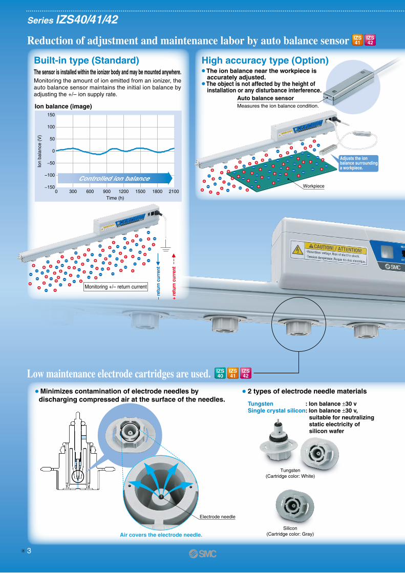
Monitoring the amount of ion emitted from an ionizer, the auto balance sensor maintains the initial ion balance by adjusting the +/– ion supply rate.
Reduction of adjustment and maintenance labor by auto balance sensor
Low maintenance electrode cartridges are used.
The sensor is installed within the ionizer body and may be mounted anywhere.
Built-in type (Standard) The ion balance near the workpiece is
accurately adjusted. The object is not affected by the height of
installation or any disturbance interference.
High accuracy type (Option)
Ions are transferred to the workpieces efficiently by using two pneumatic nozzles to improve the static neutraliza-tion performance.
Neutralization of static electricity with reduced air consumption through the use of one pneumatic nozzle.
Air covers the electrode needle.
Tungsten(Cartridge color: White)
Electrode needle
Silicon(Cartridge color: Gray)
+ re
turn
cur
rent
– re
turn
cur
rent
Monitoring +/– return current
Series IZS40/41/42
Minimizes contamination of electrode needles by discharging compressed air at the surface of the needles.
High speed static neutralization cartridges and energy saving static neutralization cartridges are available.
2 types of electrode needle materials
Tungsten : Ion balance ±30 vSingle crystal silicon: Ion balance ±30 v,
suitable for neutralizing static electricity ofsilicon wafer
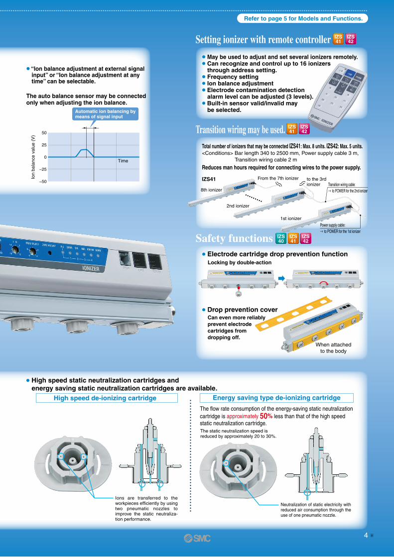
Setting ionizer with remote controller
Transition wiring may be used.
Automatic ion balancing bymeans of signal input
50
25
0
−25
−50
Ion
bala
nce
valu
e (V
)
Time
“Ion balance adjustment at external signalinput” or “Ion balance adjustment at anytime” can be selectable.
The auto balance sensor may be connectedonly when adjusting the ion balance.
May be used to adjust and set several ionizers remotely. Can recognize and control up to 16 ionizers
through address setting. Frequency setting Ion balance adjustment Electrode contamination detection
alarm level can be adjusted (3 levels). Built-in sensor valid/invalid may
be selected.
Total number of ionizers that may be connected IZS41: Max. 8 units. IZS42: Max. 5 units.<Conditions> Bar length 340 to 2500 mm, Power supply cable 3 m,
Transition wiring cable 2 m
Reduces man hours required for connecting wires to the power supply.
Safety functions Electrode cartridge drop prevention function
Locking by double-action
From the 7th ionizer to the 3rd ionizer Transition wiring cable:
→ to POWER for the 2nd ionizer
Drop prevention coverCan even more reliablyprevent electrodecartridges fromdropping off.
When attachedto the body
8th ionizer
2nd ionizer
1st ionizer
IZS41Workpiece
Adjusts the ion balance surrounding a workpiece.
Measures the ion balance condition.
Auto balance sensor
Refer to page 5 for Models and Functions.
Power supply cable: → to POWER for the 1st ionizer
IZS41
IZS42
IZS41
IZS42
IZS41
IZS42
IZS40
IZS41
IZS42
IZS40
IZS41
IZS42
High speed de-ionizing cartridge Energy saving type de-ionizing cartridge
The flow rate consumption of the energy-saving static neutralization cartridge is approximately 50% less than that of the high speed static neutralization cartridge.The static neutralization speed is reduced by approximately 20 to 30%.
3 4a
Ion balance (image)150
100
50
0
−50
−100
−1500 300 600 900 1200 1500 1800 2100
Time (h)
Ion
bala
nce
(V)
Controlled ion balance
Monitoring the amount of ion emitted from an ionizer, the auto balance sensor maintains the initial ion balance by adjusting the +/– ion supply rate.
Reduction of adjustment and maintenance labor by auto balance sensor
Low maintenance electrode cartridges are used.
The sensor is installed within the ionizer body and may be mounted anywhere.
Built-in type (Standard) The ion balance near the workpiece is
accurately adjusted. The object is not affected by the height of
installation or any disturbance interference.
High accuracy type (Option)
Ions are transferred to the workpieces efficiently by using two pneumatic nozzles to improve the static neutraliza-tion performance.
Neutralization of static electricity with reduced air consumption through the use of one pneumatic nozzle.
Air covers the electrode needle.
Tungsten(Cartridge color: White)
Electrode needle
Silicon(Cartridge color: Gray)
+ re
turn
cur
rent
– re
turn
cur
rent
Monitoring +/– return current
Series IZS40/41/42
Minimizes contamination of electrode needles by discharging compressed air at the surface of the needles.
High speed static neutralization cartridges and energy saving static neutralization cartridges are available.
2 types of electrode needle materials
Tungsten : Ion balance ±30 vSingle crystal silicon: Ion balance ±30 v,
suitable for neutralizing static electricity ofsilicon wafer
Setting ionizer with remote controller
Transition wiring may be used.
Automatic ion balancing bymeans of signal input
50
25
0
−25
−50
Ion
bala
nce
valu
e (V
)
Time
“Ion balance adjustment at external signalinput” or “Ion balance adjustment at anytime” can be selectable.
The auto balance sensor may be connectedonly when adjusting the ion balance.
May be used to adjust and set several ionizers remotely. Can recognize and control up to 16 ionizers
through address setting. Frequency setting Ion balance adjustment Electrode contamination detection
alarm level can be adjusted (3 levels). Built-in sensor valid/invalid may
be selected.
Total number of ionizers that may be connected IZS41: Max. 8 units. IZS42: Max. 5 units.<Conditions> Bar length 340 to 2500 mm, Power supply cable 3 m,
Transition wiring cable 2 m
Reduces man hours required for connecting wires to the power supply.
Safety functions Electrode cartridge drop prevention function
Locking by double-action
From the 7th ionizer to the 3rd ionizer Transition wiring cable:
→ to POWER for the 2nd ionizer
Drop prevention coverCan even more reliablyprevent electrodecartridges fromdropping off.
When attachedto the body
8th ionizer
2nd ionizer
1st ionizer
IZS41Workpiece
Adjusts the ion balance surrounding a workpiece.
Measures the ion balance condition.
Auto balance sensor
Refer to page 5 for Models and Functions.
Power supply cable: → to POWER for the 1st ionizer
IZS41
IZS42
IZS41
IZS42
IZS41
IZS42
IZS40
IZS41
IZS42
IZS40
IZS41
IZS42
High speed de-ionizing cartridge Energy saving type de-ionizing cartridge
The flow rate consumption of the energy-saving static neutralization cartridge is approximately 50% less than that of the high speed static neutralization cartridge.The static neutralization speed is reduced by approximately 20 to 30%.
3 4 a
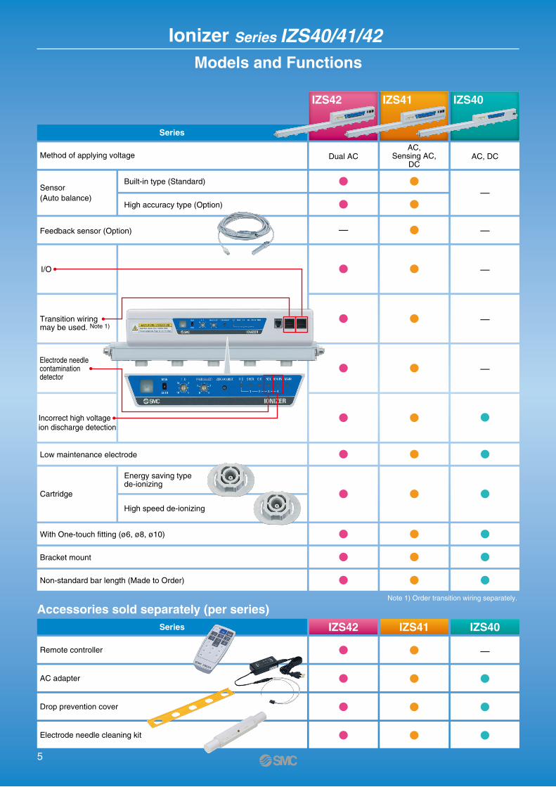
Ionizer Series IZS40/41/42 Models and Functions
Built-in type (Standard)
High accuracy type (Option)
Energy saving type de-ionizing
High speed de-ionizing
Note 1) Order transition wiring separately.
Method of applying voltage
Feedback sensor (Option)
With One-touch fitting (ø6, ø8, ø10)
Bracket mount
Non-standard bar length (Made to Order)
Low maintenance electrode
Cartridge
Remote controller
AC adapter
Drop prevention cover
Electrode needle cleaning kit
Series
AC, DC
IZS40
AC,Sensing AC,
DC
IZS41
Dual AC
IZS42
Series IZS40IZS41IZS42
Accessories sold separately (per series)
Sensor(Auto balance)
—
—
—
—
—
—
—
I/O
Transition wiring may be used. Note 1)
Incorrect high voltageion discharge detection
Electrode needlecontaminationdetector
5
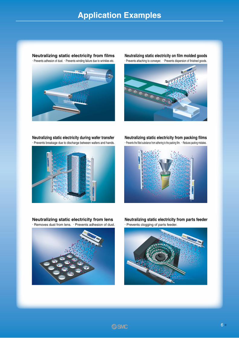
Application Examples
Neutralizing static electricity from films· Prevents adhesion of dust. · Prevents winding failure due to wrinkles etc.
Neutralizing static electricity on film molded goods· Prevents attaching to conveyer. · Prevents dispersion of finished goods.
Neutralizing static electricity during wafer transfer· Prevents breakage due to discharge between wafers and hands.
Neutralizing static electricity from packing films· Prevents the filled substance from adhering to the packing film. · Reduces packing mistakes.
Neutralizing static electricity from lens· Removes dust from lens. · Prevents adhesion of dust.
Neutralizing static electricity from parts feeder· Prevents clogging of parts feeder.
6 a
1 Hz
30 Hz
15 Hz10 Hz
5 Hz
(1 Hz)
Withfeedback
sensor
02468
101214161820
0 100 200 300 400 500
Sta
tic n
eutr
aliz
atio
n tim
e (s
ec)
Installation distance (mm)
0 500 1,000 1,500
0 500 1,000 1,500
Sta
tic n
eutr
aliz
atio
n tim
e (s
ec)
Installation distance (mm)
1 Hz
30 Hz
With feedback sensor0
2
4
6
8
10
12
0 500 1,000 1,500 2,000
30 Hz
1 Hz
With feedback sensor0
2
1
4
3
5
6
7
8
0
2
1
4
3
5
6
7
8
2,000
Sta
tic n
eutr
aliz
atio
n tim
e (s
ec)
Installation distance (mm)
1 Hz
30 Hz
2,000
Sta
tic n
eutr
aliz
atio
n tim
e (s
ec)
Installation distance (mm)
1 Hz
30 Hz
0
2
4
6
8
10
12
0 500 1,000 1,500
0 500 1,000 1,500
0 500 1,000 1,500
2,000
Sta
tic n
eutr
aliz
atio
n tim
e (s
ec)
Installation distance (mm)
30 Hz 1 Hz
2,000
Sta
tic n
eutr
aliz
atio
n tim
e (s
ec)
Installation distance (mm)
1 Hz30 Hz
0
2
1
4
5
3
6
0
2
1
4
5
3
6
2,000
Sta
tic n
eutr
aliz
atio
n tim
e (s
ec)
Installation distance (mm)
With feedback sensor With feedback sensor
With feedback sensor
With feedback sensor
Series IZS40/41/42 Technical Data
Feedback sensor installation distance: 25 mm
Feedback sensor installation distance: 25 mm
Feedback sensor installation distance: 25 mm
Feedback sensor installation distance: 25 mm
Feedback sensor installation distance: 25 mm
Feedback sensor installation distance: 25 mm
Feedback sensor installation distance: 25 mm
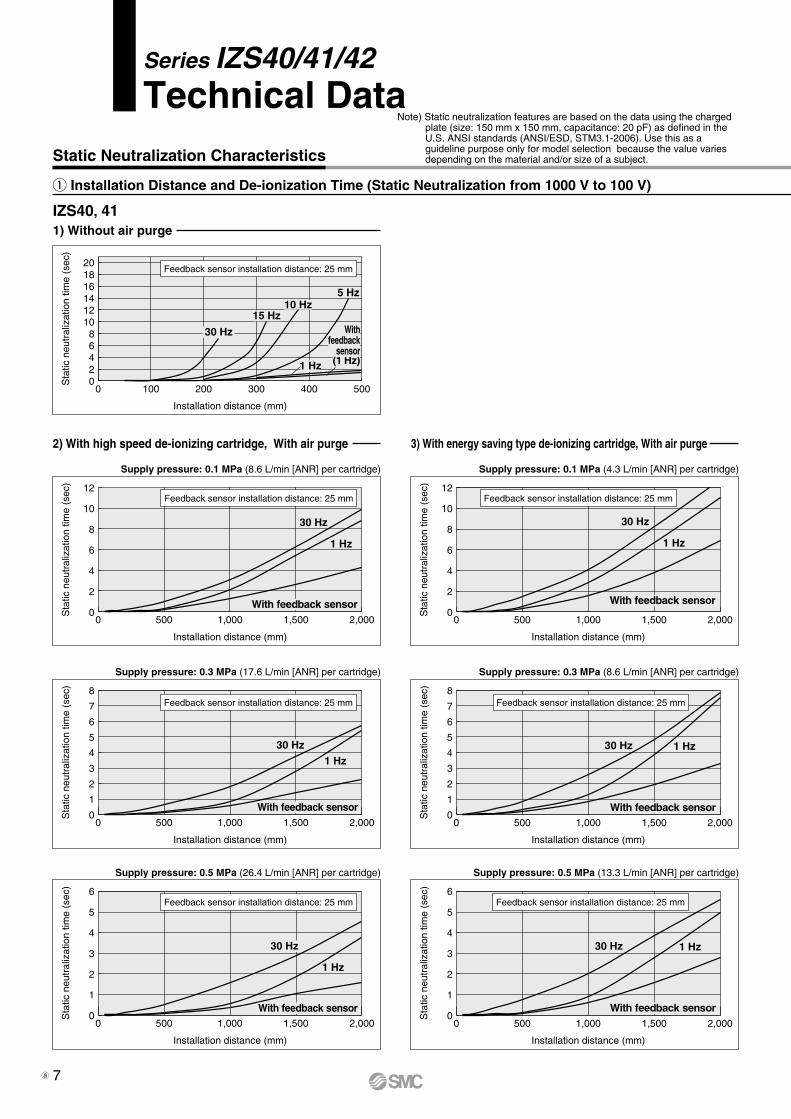
IZS40, 411) Without air purge
2) With high speed de-ionizing cartridge, With air purge 3) With energy saving type de-ionizing cartridge, With air purge
Supply pressure: 0.5 MPa (26.4 L/min [ANR] per cartridge)
Supply pressure: 0.3 MPa (17.6 L/min [ANR] per cartridge)
Supply pressure: 0.1 MPa (8.6 L/min [ANR] per cartridge) Supply pressure: 0.1 MPa (4.3 L/min [ANR] per cartridge)
Supply pressure: 0.3 MPa (8.6 L/min [ANR] per cartridge)
Supply pressure: 0.5 MPa (13.3 L/min [ANR] per cartridge)
q Installation Distance and De-ionization Time (Static Neutralization from 1000 V to 100 V)
Static Neutralization Characteristics
Note) Static neutralization features are based on the data using the charged plate (size: 150 mm x 150 mm, capacitance: 20 pF) as defined in the U.S. ANSI standards (ANSI/ESD, STM3.1-2006). Use this as a guideline purpose only for model selection because the value varies depending on the material and/or size of a subject.
7a
1 Hz
30 Hz
02468
101214161820
0 500 1,000 1,500 2,000
Sta
tic n
eutr
aliz
atio
n tim
e (s
ec)
Installation distance (mm)
30 Hz1 Hz
0
2
4
6
8
10
12
0 500 1,000 1,500 2,000
Sta
tic n
eutr
aliz
atio
n tim
e (s
ec)
Installation distance (mm)
1 Hz30 Hz
02468
101214161820
0 50 100 150 200 250 300
Sta
tic n
eutr
aliz
atio
n tim
e (s
ec)
Installation distance (mm)
30 Hz1 Hz
0
2
1
4
3
6
5
7
8
0 500 1,000 1,500 2,000
Sta
tic n
eutr
aliz
atio
n tim
e (s
ec)
Installation distance (mm)
1 Hz
30 Hz
02468
101214161820
0 500 1,000 1,500 2,000
Sta
tic n
eutr
aliz
atio
n tim
e (s
ec)
Installation distance (mm)
30 Hz 1 Hz
0
2
4
6
8
10
12
0 500 1,000 1,500 2,000
Sta
tic n
eutr
aliz
atio
n tim
e (s
ec)
Installation distance (mm)
1 Hz30 Hz
0
2
1
4
3
6
5
7
8
0 500 1,000 1,500 2,000
Sta
tic n
eutr
aliz
atio
n tim
e (s
ec)
Installation distance (mm)
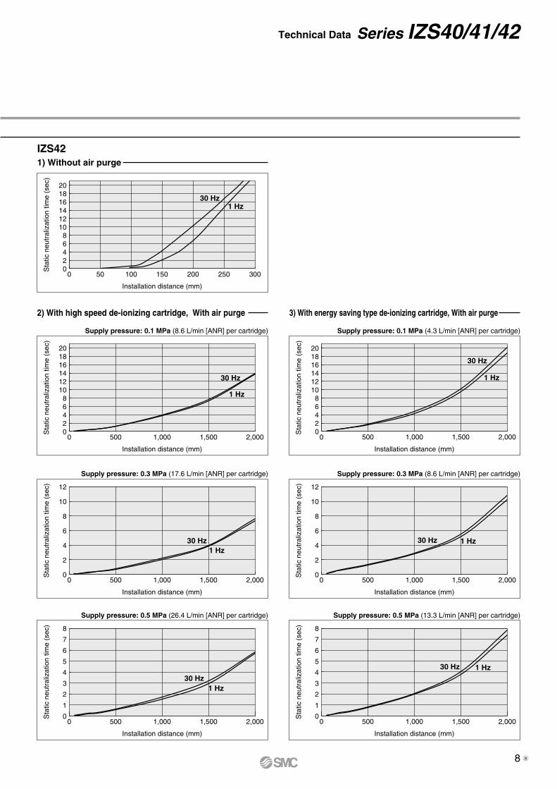
IZS421) Without air purge
2) With high speed de-ionizing cartridge, With air purge 3) With energy saving type de-ionizing cartridge, With air purge
Supply pressure: 0.5 MPa (26.4 L/min [ANR] per cartridge)
Supply pressure: 0.3 MPa (17.6 L/min [ANR] per cartridge) Supply pressure: 0.3 MPa (8.6 L/min [ANR] per cartridge)
Supply pressure: 0.5 MPa (13.3 L/min [ANR] per cartridge)
Supply pressure: 0.1 MPa (8.6 L/min [ANR] per cartridge) Supply pressure: 0.1 MPa (4.3 L/min [ANR] per cartridge)
Technical Data Series IZS40/41/42
8 a
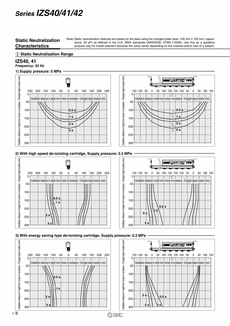
IZS40, 41Frequency: 30 Hz
2) With high speed de-ionizing cartridge, Supply pressure: 0.3 MPa
3) With energy saving type de-ionizing cartridge, Supply pressure: 0.3 MPa
1) Supply pressure: 0 MPa
w Static Neutralization Range
Static NeutralizationCharacteristics
0
50
100
150
200
250
300
050100150 50 100 150 150 100 50 0 50 100 150
Instal
lation
dista
nce i
n heig
ht fro
m ion
izer to
work
piece
- Cha
rged o
bject
locati
on (m
m)
Installation distance in width from ionizer to workpiece - Charged object location (mm)
5 s
2 s
1 s
0.5 s
0
50
100
150
200
250
300
250 200 150 100 50 0 50 100 150 200 250
Instal
lation
dista
nce i
n heig
ht fro
m ion
izer to
work
piece
- Cha
rged o
bject
locati
on (m
m)
Instal
lation
dista
nce i
n heig
ht fro
m ion
izer to
work
piece
- Cha
rged o
bject
locati
on (m
m)
Instal
lation
dista
nce i
n heig
ht fro
m ion
izer to
work
piece
- Cha
rged o
bject
locati
on (m
m)
Installation distance in depth from ionizer to workpiece - Charged object location (mm)
5 s
2 s
1 s
0.5 s
0
50
100
150
200
250
300
150 100 50 0 50 100 150 150 100 50 0 50 100 150
5 s
2 s
1 s
0.5 s
0
50
100
150
200
250
300
250 200 150 100 50 0 50 100 150 200 250
5 s
2 s
1 s
0.5 s
0
50
100
150
200
250
300
150 100 50 0 50 100 150 150 100 50 0 50 100 150
5 s
2 s1 s
0.5 s
0
50
100
150
200
250
300
250 200 150 100 50 0 50 100 150 200 250
5 s
2 s
1 s0.5 s
Note) Static neutralization features are based on the data using the charged plate (size: 150 mm x 150 mm, capaci-tance: 20 pF) as defined in the U.S. ANSI standards (ANSI/ESD, STM3.1-2006). Use this as a guideline purpose only for model selection because the value varies depending on the material and/or size of a subject.
Installation distance in width from ionizer to workpiece - Charged object location (mm)Installation distance in depth from ionizer to workpiece - Charged object location (mm)
Instal
lation
dista
nce i
n heig
ht fro
m ion
izer to
work
piece
- Cha
rged o
bject
locati
on (m
m)
Instal
lation
dista
nce i
n heig
ht fro
m ion
izer to
work
piece
- Cha
rged o
bject
locati
on (m
m)
Installation distance in width from ionizer to workpiece - Charged object location (mm)Installation distance in depth from ionizer to workpiece - Charged object location (mm)
Series IZS40/41/42
9a
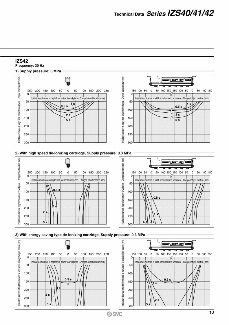
2) With high speed de-ionizing cartridge, Supply pressure: 0.3 MPa
3) With energy saving type de-ionizing cartridge, Supply pressure: 0.3 MPa
IZS42Frequency: 30 Hz
1) Supply pressure: 0 MPa
0
50
100
150
200
250
300
150 100 50 0 50 100 150 150 100 50 0 50 100 150
5 s
2 s
1 s0.5 s
0
50
100
150
200
250
300
250 200 150 100 50 0 50 100 150 200 250
5 s
2 s
1 s0.5 s
0
50
100
150
200
250
300
150 100 50 0 50 100 150 150 100 50 0 50 100 150
5 s2 s
1 s0.5 s
0
50
100
150
200
250
300
250 200 150 100 50 0 50 100 150 200 250
5 s
2 s
1 s
0.5 s
0
50
100
150
200
250
300
150 100 50 0 50 100 150 150 100 50 0 50 100 150
5 s 2 s
1 s
0.5 s
0
50
100
150
200
250
300
250 200 150 100 50 0 50 100 150 200 250
5 s
2 s
1 s
0.5 s
Instal
lation
dista
nce i
n heig
ht fro
m ion
izer to
work
piece
- Cha
rged o
bject
locati
on (m
m)
Installation distance in width from ionizer to workpiece - Charged object location (mm)
Instal
lation
dista
nce i
n heig
ht fro
m ion
izer to
work
piece
- Cha
rged o
bject
locati
on (m
m)
Installation distance in depth from ionizer to workpiece - Charged object location (mm)
Instal
lation
dista
nce i
n heig
ht fro
m ion
izer to
work
piece
- Cha
rged o
bject
locati
on (m
m)
Installation distance in width from ionizer to workpiece - Charged object location (mm)
Instal
lation
dista
nce i
n heig
ht fro
m ion
izer to
work
piece
- Cha
rged o
bject
locati
on (m
m)
Installation distance in depth from ionizer to workpiece - Charged object location (mm)
Technical Data Series IZS40/41/42
10
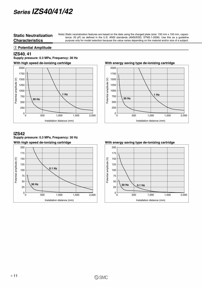
IZS40, 41
IZS42
With high speed de-ionizing cartridge
Supply pressure: 0.3 MPa, Frequency: 30 Hz
Supply pressure: 0.3 MPa, Frequency: 30 Hz
1 Hz
30 Hz
0
500
250
1000
750
1500
1250
1750
2000
0
500
250
1000
750
1500
1250
1750
2000
0 500 1,000 1,500 2,000
Pot
entia
l am
plitu
de (
V)
Installation distance (mm)
With high speed de-ionizing cartridge
0.1 Hz
30 Hz
0
50
25
100
75
150
125
175
200
0
50
25
100
75
150
125
175
200
0 500 1,000 1,500 2,000
Pot
entia
l am
plitu
de (
V)
Installation distance (mm)
With energy saving type de-ionizing cartridge
1 Hz30 Hz
0 500 1,000 1,500 2,000
Pot
entia
l am
plitu
de (
V)
Installation distance (mm)
With energy saving type de-ionizing cartridge
0.1 Hz30 Hz
0 500 1,000 1,500 2,000
Pot
entia
l am
plitu
de (
V)
Installation distance (mm)
e Potential Amplitude
Static NeutralizationCharacteristics
Note) Static neutralization features are based on the data using the charged plate (size: 150 mm x 150 mm, capaci-tance: 20 pF) as defined in the U.S. ANSI standards (ANSI/ESD, STM3.1-2006). Use this as a guideline purpose only for model selection because the value varies depending on the material and/or size of a subject.
Series IZS40/41/42
11a
Detection hole
Sensor head
Detection hole
Detection range
Inst
alla
tion
dist
ance
Detection range
45
100
180
Installation distance
10
25
50
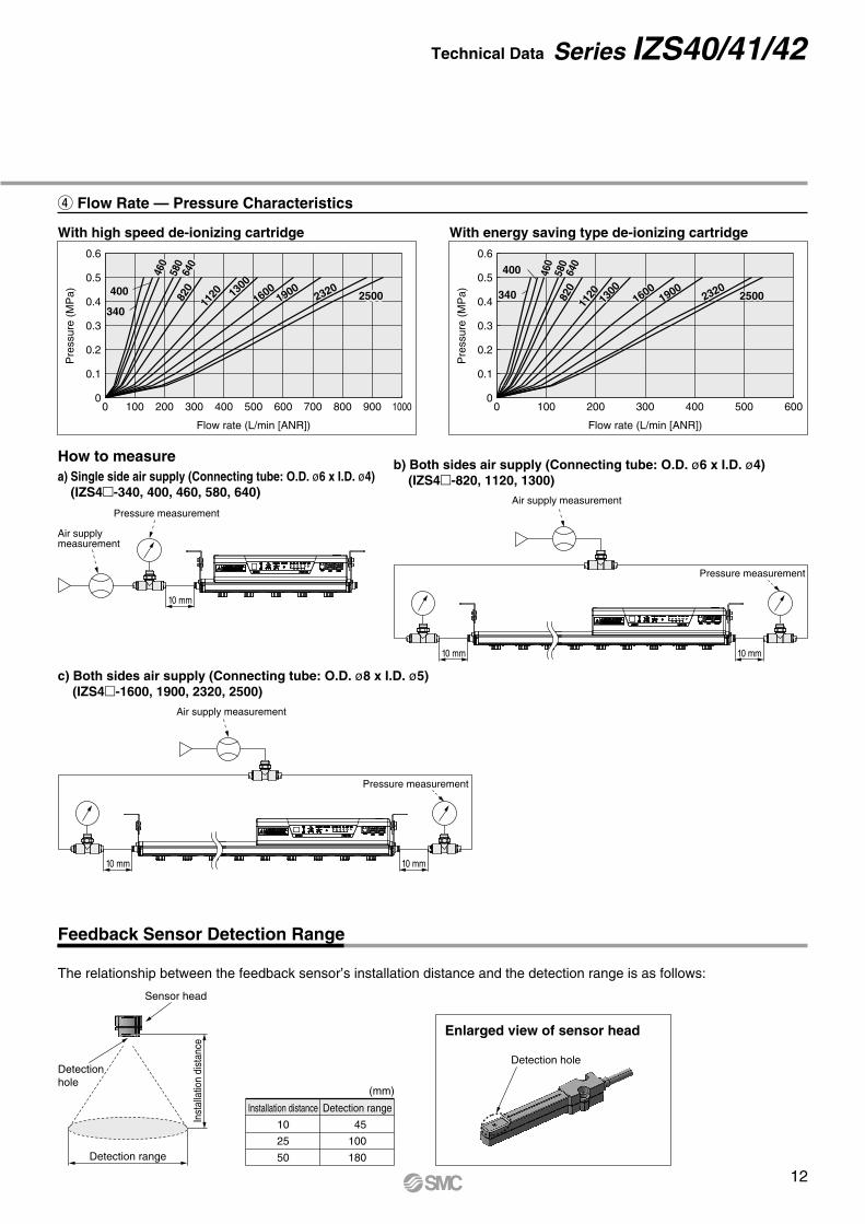
The relationship between the feedback sensor’s installation distance and the detection range is as follows:
How to measurea) Single side air supply (Connecting tube: O.D. ø6 x I.D. ø4) (IZS4-340, 400, 460, 580, 640)
Air supply measurement
Pressure measurement
Pressure measurement
Air supply measurement
10 mm
b) Both sides air supply (Connecting tube: O.D. ø6 x I.D. ø4) (IZS4-820, 1120, 1300)
c) Both sides air supply (Connecting tube: O.D. ø8 x I.D. ø5) (IZS4-1600, 1900, 2320, 2500)
r Flow Rate — Pressure Characteristics
Feedback Sensor Detection Range
(mm)
Enlarged view of sensor head
Pressure measurement
Air supply measurement
With high speed de-ionizing cartridge With energy saving type de-ionizing cartridge
0
0.1
0.2
0.3
0.4
0.5
0.6
0 100 200 300 400 500 600 700 800 900 1000
Flow rate (L/min [ANR])
Pre
ssur
e (M
Pa)
0
0.1
0.2
0.3
0.4
0.5
0.6
0 100 200 300 400 500 600
Flow rate (L/min [ANR])
Pre
ssur
e (M
Pa)
34025002320
19001600
112082
058
064
0
460
400 1300
250023201900
1600
1300
112082
064
058
0
460
400
340
10 mm
10 mm 10 mm
10 mm
Technical Data Series IZS40/41/42
12
RoHS
IZS 40IZS
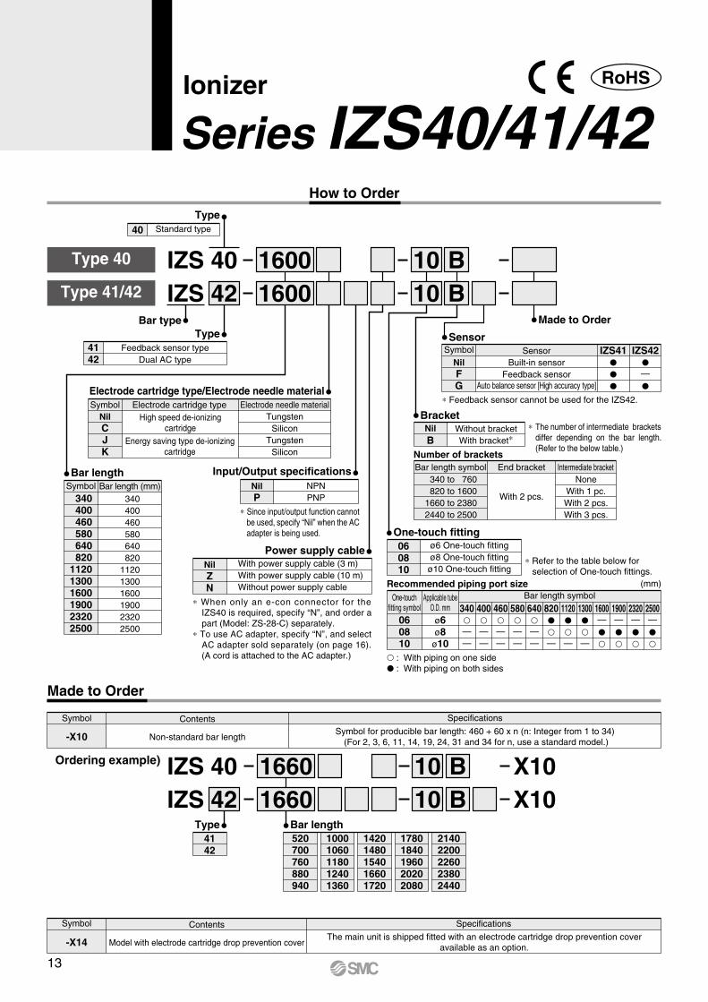
Bar typeType
4142
Feedback sensor typeDual AC type
Type40 Standard type
∗ Since input/output function cannot be used, specify “Nil” when the AC adapter is being used.
∗ When only an e-con connector for the IZS40 is required, specify “N”, and order a part (Model: ZS-28-C) separately.
∗ To use AC adapter, specify “N”, and select AC adapter sold separately (on page 16). (A cord is attached to the AC adapter.)
∗ The number of intermediate brackets differ depending on the bar length. (Refer to the below table.)
∗ Refer to the table below for selection of One-touch fittings.
∗ Feedback sensor cannot be used for the IZS42.
Made to Order
340 400 460 580 640 820112013001600190023202500
Bar length (mm) 340 400 460 580 640 820112013001600190023202500
SymbolBar length
Electrode cartridge type/Electrode needle materialSymbol
NilCJK
Electrode needle materialTungsten
SiliconTungsten
Silicon
Electrode cartridge typeHigh speed de-ionizing
cartridge
Energy saving type de-ionizingcartridge
Input/Output specificationsNilP
NPNPNP
NilZN
With power supply cable (3 m)With power supply cable (10 m)Without power supply cable
Power supply cable
NilFG
Symbol SensorBuilt-in sensor
Feedback sensorAuto balance sensor [High accuracy type]
—
IZS41 IZS42Sensor
BracketNilB
Without bracketWith bracket∗
340 to 760 820 to 16001660 to 23802440 to 2500
Bar length symbol End bracket Intermediate bracket
With 2 pcs.
NoneWith 1 pc.With 2 pcs.With 3 pcs.
Number of brackets
One-touch fitting060810
ø6 One-touch fittingø8 One-touch fittingø10 One-touch fitting
060810
Bar length symbolOne-touchfitting symbol
ø6ø8
ø10
Applicable tubeO.D. mm
——
340——
400——
460——
580——
640—
820—
1120—
1300—
1600—
1900—
2320—
2500
Recommended piping port size (mm)
Type 40
Type 41/42
X10X10
IZS 40IZS
Type4142
SpecificationsContents
Non-standard bar lengthSymbol for producible bar length: 460 + 60 x n (n: Integer from 1 to 34)
(For 2, 3, 6, 11, 14, 19, 24, 31 and 34 for n, use a standard model.)
Symbol
-X10
Ordering example)
520700760880940
10001060118012401360
14201480154016601720
17801840196020202080
21402200226023802440
Bar length
Made to Order
SpecificationsContents
Model with electrode cartridge drop prevention coverThe main unit is shipped fitted with an electrode cartridge drop prevention cover
available as an option.
Symbol
-X14
: With piping on one side : With piping on both sides
How to Order
4216001600
1010
BB
4216601660
1010
BB
Ionizer
Series IZS40/41/42
13
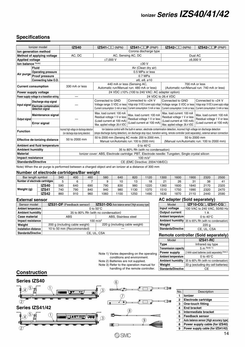
Specifications
Number of electrode cartridges/Bar weight
External sensor
Construction
Number of electrode cartridges
Weight (g)IZS40IZS41IZS42
Bar length symbol
Ambient temperatureAmbient humidityCase materialImpact resistanceWeightInstallation distanceStandards/Directive
0 to 50°C35 to 80% Rh (with no condensation)
ABS
200 g (including cable weight)10 to 50 mm (Recommended)
220 g (including cable weight)—
CE, UL, CSA
100 m/s2ABS, Stainless steel
340 5590740860
400 6640790910
460 7690840960
580 9 790 9401060
640 10 830 9801100
820 13 98011301250
1120 18122013701490
1300 21136015101630
1600 26160017501870
1900 31184019902110
2320 38217023202440
2500 41232024702590
Sensor model IZS31-DF (Feedback sensor) IZS31-DG (Auto balance sensor) [High accuracy type]
FluidOperating pressureProof pressureConnecting tube O.D.
Discharge stop signalElectrode contamination detection signal
Maintenance signal
Error signal
IZS41- (NPN) IZS41-P (PNP) IZS42- (NPN) IZS42-P (PNP)IZS40
AC, Sensing AC, DC
±30 VAir (Clean dry air)0.5 MPa or less
0.7 MPaø6, ø8, ø10
24 VDC ±10% (100 to 240 VAC: AC adapter option)
±7,000 V
—
—
—
Dual AC±6,000 V
AC, DCCorona discharge type
Ion balance control with the built-in sensor, electrode contamination detection, incorrect high voltage ion discharge detection(stops discharge during detection), ion discharge stop input, transition wiring, remote controller (sold separately), external sensor connection
0 to 40°C35 to 80% Rh (with no condensation)
Ionizer cover: ABS, Electrode cartridge: PBT, Electrode needle: Tungsten, Single crystal silicon100 m/s2
CE (EMC Directive: 2004/108/EC)
50 to 2000 mm (Sensing AC mode: 200 to 2000 mm,Manual run/Automatic run: 100 to 2000 mm)
50 to 2000 mm(Manual run/Automatic run: 100 to 2000 mm)
50 to 2000 mm
Incorrect high voltage ion discharge detection(Ion discharge stops during detection)
Ionizer model
Max. load current: 100 mAResidual voltage 1 V or less(Load current at 100 mA)Max. applied voltage: 26.4 VDC
Connected to GNDVoltage range: 5 VDC or lessCurrent consumption: 5 mA or less
Connected to +24 VVoltage range: 19 VDC to power supply voltageCurrent consumption: 5 mA or less
Connected to GNDVoltage range: 5 VDC or lessCurrent consumption: 5 mA or less
Connected to +24 VVoltage range: 19 VDC to power supply voltageCurrent consumption: 5 mA or less
Max. load current: 100 mAResidual voltage 1 V or less(Load current at 100 mA)
Max. load current: 100 mAResidual voltage 1 V or less(Load current at 100 mA)Max. applied voltage: 26.4 VDC
Max. load current: 100 mAResidual voltage 1 V or less(Load current at 100 mA)
Ion generation methodMethod of applying voltageApplied voltageIon balance Note)
Air purge
Current consumption
Power supply voltagePower supply voltage in a transition wiring
Effective de-ionizing distance
Ambient and fluid temperatureAmbient humidityMaterialImpact resistanceStandards/Directive
Input signal
Output signal
Function
440 mA or less (Sensing AC,Automatic run/Manual run: 480 mA or less)330 mA or less
700 mA or less(Automatic run/Manual run: 740 mA or less)
123456789
DescriptionNo.IonizerElectrode cartridgeOne-touch fittingEnd bracketIntermediate bracketFeedback sensorAuto balance sensor [High accuracy type]Power supply cable (for IZS40)Power supply cable (for IZS41/42)
Note) When the air purge is performed between a charged object and an ionizer at a distance of 300 mm
AC adapter (Sold separately)
Remote controller (Sold separately)
24 VDC to 26.4 VDC
Input voltageOutput currentAmbient temperatureAmbient humidityWeightStandards/Directive
TypeTransmission capacityPower supplyAmbient temperatureAmbient humidityWeightStandards/Directive
100 VAC to 240 VAC, 50/60 Hz1 A
0 to 40°C35 to 65% Rh (with no condensation)
220 gCE, UL, CSA
Infrared ray type5 m Note 1)
2 AAA sized batteries (sold separately) Note 2)
0 to 45°C35 to 80% Rh (with no condensation)33 g (excluding dry cell batteries)
CE
Model
Model
IZF10-CG, IZS41-CG
IZS41-RC
Series IZS41/42
Series IZS40
rt
w
qe
w
rt q
e
y
u
i
o
Note 1) Varies depending on the operating conditions and environment.
Note 2) Batteries are not supplied.Note 3) Refer to the operation manual for
handling of the remote controller.
Ionizer Series IZS40/41/42
14
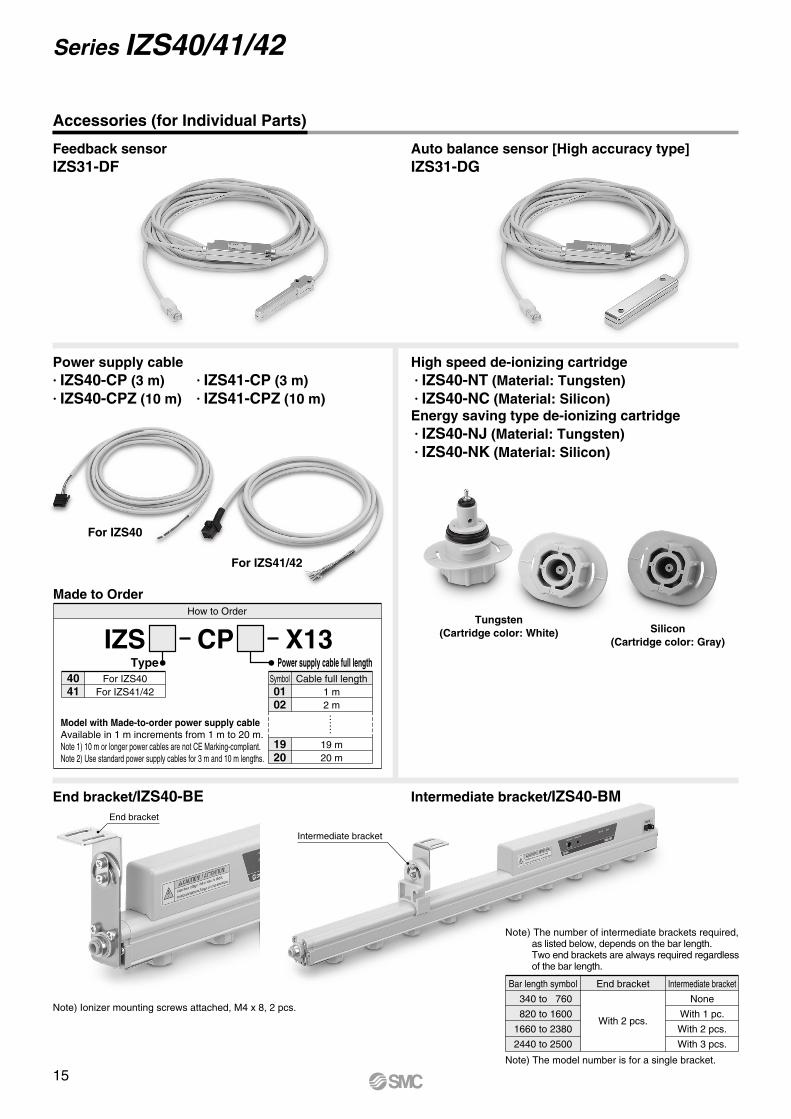
Feedback sensorIZS31-DF
Power supply cable· IZS40-CP (3 m) · IZS41-CP (3 m)· IZS40-CPZ (10 m) · IZS41-CPZ (10 m)
End bracket/IZS40-BE Intermediate bracket/IZS40-BM
Auto balance sensor [High accuracy type]IZS31-DG
End bracket
Intermediate bracket
Accessories (for Individual Parts)
High speed de-ionizing cartridge· IZS40-NT (Material: Tungsten)· IZS40-NC (Material: Silicon)Energy saving type de-ionizing cartridge· IZS40-NJ (Material: Tungsten)· IZS40-NK (Material: Silicon)
Note) The number of intermediate brackets required, as listed below, depends on the bar length.Two end brackets are always required regardless of the bar length.
Note) The model number is for a single bracket.
Note) Ionizer mounting screws attached, M4 x 8, 2 pcs.
For IZS41/42
For IZS40
Tungsten(Cartridge color: White) Silicon
(Cartridge color: Gray)
340 to 760
820 to 1600
1660 to 2380
2440 to 2500
Bar length symbol End bracket Intermediate bracket
With 2 pcs.
None
With 1 pc.
With 2 pcs.
With 3 pcs.
How to Order
Model with Made-to-order power supply cableAvailable in 1 m increments from 1 m to 20 m.Note 1) 10 m or longer power cables are not CE Marking-compliant.Note 2) Use standard power supply cables for 3 m and 10 m lengths.
Made to Order
Symbol0102
1920
Cable full length1 m2 m
19 m20 m
Power supply cable full length
IZS CP X13
……
4041
For IZS40For IZS41/42
Type
Series IZS40/41/42
15
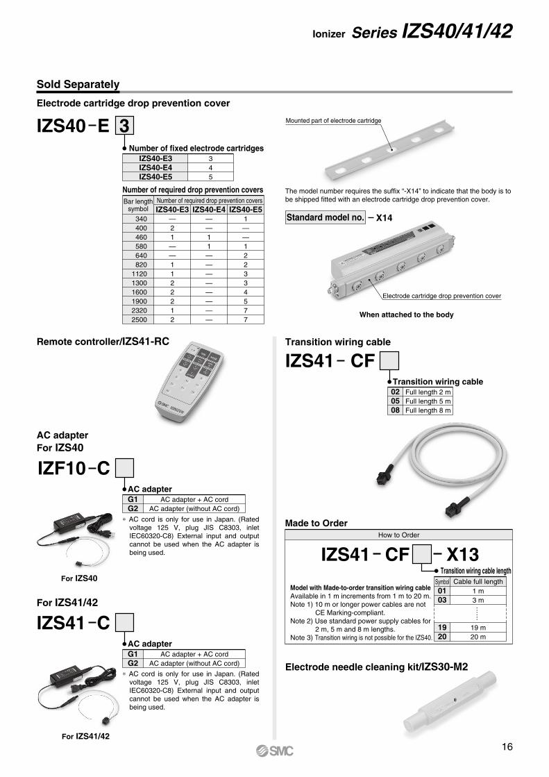
Electrode needle cleaning kit/IZS30-M2
The model number requires the suffix “-X14” to indicate that the body is to be shipped fitted with an electrode cartridge drop prevention cover.
X14
Number of fixed electrode cartridges345
IZS40-E3IZS40-E4IZS40-E5
Bar lengthsymbol
340400460580640820
112013001600190023202500
Number of required drop prevention covers
Number of required drop prevention covers
IZS40-E3 IZS40-E4 IZS40-E5—21——1122212
——11————————
1——122334577
Electrode cartridge drop prevention cover
When attached to the body
3IZS40 E
AC adapterFor IZS40
For IZS41/42
IZS41 CF020508
Full length 2 mFull length 5 mFull length 8 m
Transition wiring cable
Transition wiring cableRemote controller/IZS41-RC
G1G2
AC adapter + AC cordAC adapter (without AC cord)
AC adapter
IZF10 C
∗ AC cord is only for use in Japan. (Rated voltage 125 V, plug JIS C8303, inlet IEC60320-C8) External input and output cannot be used when the AC adapter is being used.
∗ AC cord is only for use in Japan. (Rated voltage 125 V, plug JIS C8303, inlet IEC60320-C8) External input and output cannot be used when the AC adapter is being used.
G1G2
AC adapter + AC cordAC adapter (without AC cord)
AC adapter
IZS41 C
Mounted part of electrode cartridge
Standard model no.
For IZS40
For IZS41/42
How to Order
Model with Made-to-order transition wiring cableAvailable in 1 m increments from 1 m to 20 m.Note 1) 10 m or longer power cables are not CE Marking-compliant.Note 2) Use standard power supply cables for 2 m, 5 m and 8 m lengths.Note 3) Transition wiring is not possible for the IZS40.
Made to Order
Symbol0103
1920
Cable full length1 m3 m
19 m20 m
Transition wiring cable length
IZS41 CF X13
……
Ionizer Series IZS40/41/42
Sold Separately
Electrode cartridge drop prevention cover
16
F.G.
Ionizer (IZS40)
+ Powersupply
24 VDCGND
Inte
rnal
cir
cuit 1
2
3
4 (Unused)
Shield
Brown
Blue
Green
A
F.G.
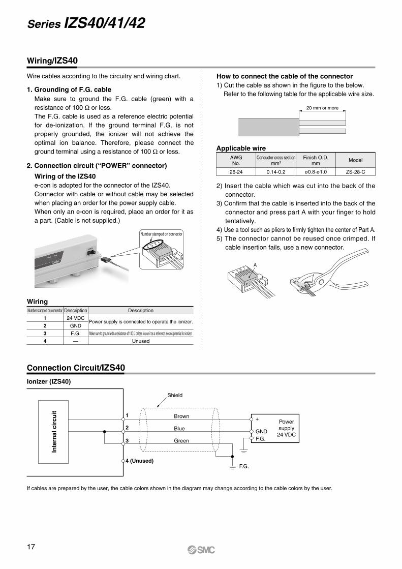
Make sure to ground the F.G. cable (green) with a resistance of 100 Ω or less.The F.G. cable is used as a reference electric potential for de-ionization. If the ground terminal F.G. is not properly grounded, the ionizer will not achieve the optimal ion balance. Therefore, please connect the ground terminal using a resistance of 100 Ω or less.
1. Grounding of F.G. cable
2. Connection circuit (“POWER” connector)
Wire cables according to the circuitry and wiring chart.
Wiring of the IZS40e-con is adopted for the connector of the IZS40.Connector with cable or without cable may be selected when placing an order for the power supply cable.When only an e-con is required, place an order for it as a part. (Cable is not supplied.)
How to connect the cable of the connector1) Cut the cable as shown in the figure to the below.
Refer to the following table for the applicable wire size.
2) Insert the cable which was cut into the back of the connector.
3) Confirm that the cable is inserted into the back of the connector and press part A with your finger to hold tentatively.
4) Use a tool such as pliers to firmly tighten the center of Part A.5) The connector cannot be reused once crimped. If
cable insertion fails, use a new connector.
Number stamped on connector
WiringDescription Description
Power supply is connected to operate the ionizer.
Make sure to ground with a resistance of 100 Ω or less to use it as a reference electric potential for ionizer.
Unused
24 VDC
GND
F.G.
—
Number stamped on connector
1
2
3
4
Applicable wireConductor cross section
mm2
0.14-0.2
Finish O.D.mm
ø0.8-ø1.0
Model
ZS-28-C
AWGNo.
26-24
20 mm or more
Wiring/IZS40
Connection Circuit/IZS40
If cables are prepared by the user, the cable colors shown in the diagram may change according to the cable colors by the user.
Series IZS40/41/42
17
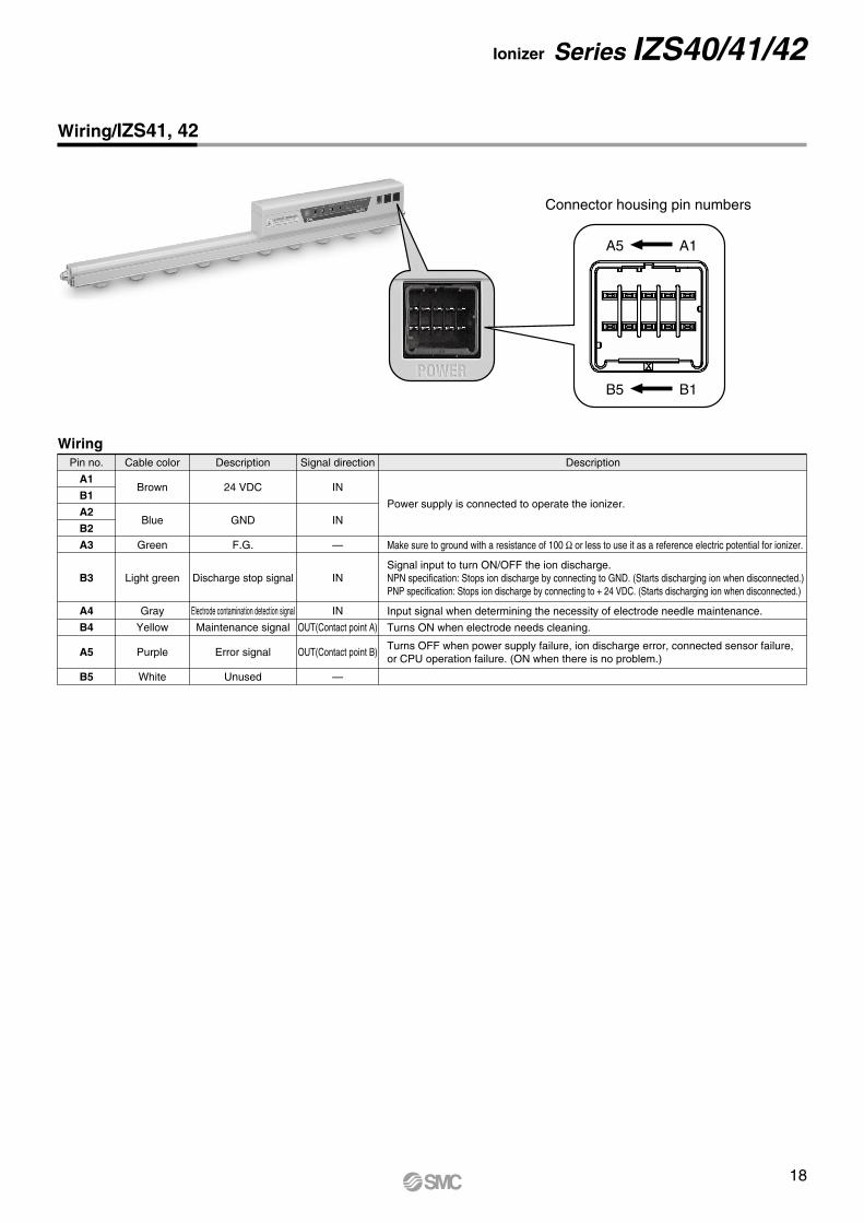
Wiring/IZS41, 42
Pin no. Cable color
Brown
Blue
Green
Light green
Gray
Yellow
Purple
White
Description
24 VDC
GND
F.G.
Discharge stop signal
Electrode contamination detection signal
Maintenance signal
Error signal
Unused
Signal direction
IN
IN
—
IN
IN
OUT(Contact point A)
OUT(Contact point B)
—
Description
Signal input to turn ON/OFF the ion discharge.NPN specification: Stops ion discharge by connecting to GND. (Starts discharging ion when disconnected.)PNP specification: Stops ion discharge by connecting to + 24 VDC. (Starts discharging ion when disconnected.)
Power supply is connected to operate the ionizer.
Make sure to ground with a resistance of 100 Ω or less to use it as a reference electric potential for ionizer.
Input signal when determining the necessity of electrode needle maintenance.
Turns ON when electrode needs cleaning.
Turns OFF when power supply failure, ion discharge error, connected sensor failure,or CPU operation failure. (ON when there is no problem.)
A1
B1
A2
B2
A3
B3
A4
B4
A5
B5
Wiring
Connector housing pin numbers
B5 B1
A5 A1
Ionizer Series IZS40/41/42
18
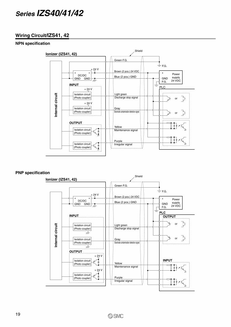
+ Powersupply
24 VDCGNDF.G.
+ +
GND GNDDC/DC
F.G.
PLCINPUT
Isolation circuit(Photo coupler)
Isolation circuit(Photo coupler)
Isolation circuit(Photo coupler)
Isolation circuit(Photo coupler)
OUTPUT
or
+ 24 V
+ 24 V
+ 24 V
Ionizer (IZS41, 42)
or
Brown (2 pcs.) 24 VDC
Green F.G.
Blue (2 pcs.) GND
Light green Discharge stop signal
Gray Electrode contamination detection signal
Yellow Maintenance signal
Purple Irregular signal
Inte
rnal
cir
cuit
Inte
rnal
cir
cuit
Shield
+ Powersupply
24 VDCGND
+ +
GND GNDDC/DC
F.G.
PLCINPUT
INPUT
Isolation circuit(Photo coupler)
Isolation circuit(Photo coupler)
Isolation circuit(Photo coupler)
Isolation circuit(Photo coupler)
OUTPUT
or
+ 24 V
Ionizer (IZS41, 42)
or
Brown (2 pcs.) 24 VDC
Green F.G.
Blue (2 pcs.) GND
Light greenDischarge stop signal
Gray Electrode contamination detection signal
Yellow Maintenance signal
Purple Irregular signal
Shield
+ 24 V
+ 24 V
OUTPUT
F.G.
NPN specification
PNP specification
Wiring Circuit/IZS41, 42
Series IZS40/41/42
19
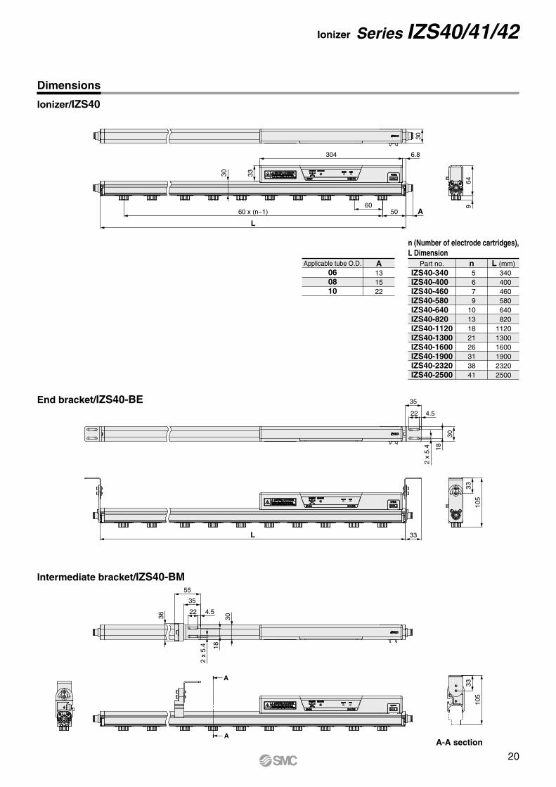
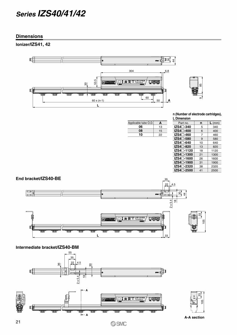
Part no. n 5 6 7 91013182126313841
340 400 460 580 640 820112013001600190023202500
L (mm)IZS40-340IZS40-400IZS40-460IZS40-580IZS40-640IZS40-820IZS40-1120IZS40-1300IZS40-1600IZS40-1900IZS40-2320IZS40-2500
A-A section
n (Number of electrode cartridges), L Dimension
Applicable tube O.D. A131522
060810
Dimensions
Ionizer/IZS40
End bracket/IZS40-BE
Intermediate bracket/IZS40-BM
A
A
30
304 6.8
605060 x (n−1)
L
33
A
649
35
22 4.5
30
18
2 x
5.4
L 33
105
33
36
30
55
35
22 4.5
30
2 x
5.4 18
105
33
Ionizer Series IZS40/41/42
20
A-A section
Dimensions
Ionizer/IZS41, 42
End bracket/IZS40-BE
Intermediate bracket/IZS40-BM
Part no. n 5 6 7 91013182126313841
340 400 460 580 640 820112013001600190023202500
L (mm)IZS4-340IZS4-400IZS4-460IZS4-580IZS4-640IZS4-820IZS4-1120IZS4-1300IZS4-1600IZS4-1900IZS4-2320IZS4-2500
n (Number of electrode cartridges), L Dimension
Applicable tube O.D. A131522
060810
A
A
4430
859
304 6.8
30 53.5
60 x (n-1)
L
6050 A
4430
18
2 x
5.4
35
22 4.5
105
33
L 33
36
55
35
22 4.5
30
18
2 x
5.4
105
33
Series IZS40/41/42
21
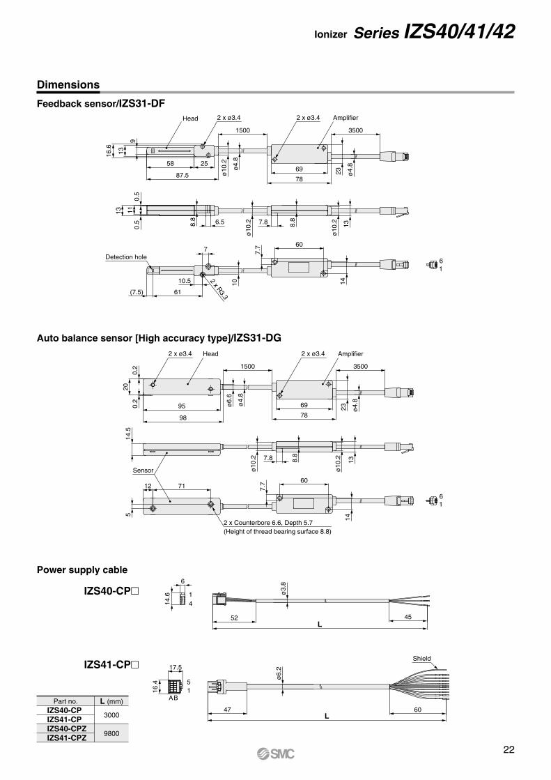
Dimensions
Feedback sensor/IZS31-DF
Auto balance sensor [High accuracy type]/IZS31-DG
Power supply cable
Part no.
3000
9800
L (mm)IZS40-CPIZS41-CPIZS40-CPZIZS41-CPZ
IZS40-CP
IZS41-CP
7
16
16
Head
SM
C
41
BA15
9
1316.6
2558
87.5
2 x ø3.4
1500
ø4.
8
ø10
.2
2 x ø3.4 Amplifier
3500
23 ø4.
8
69
78
1113
0.5
0.5
6.58.8 7.8
ø10
.2
ø10
.2 1314
8.8
Detection hole
61(7.5)
10.5 2 x R3.3
10
60
7.7
2 x ø3.4
20
98
950.2
0.2
Head
1500
ø4.
8
ø6.
6
2 x ø3.4 Amplifier
69
78
3500
ø4.
8
23
Sensor
14.5
5
7.8 8.8
ø10
.2 13
ø10
.2
14
60
7.7
2 x Counterbore 6.6, Depth 5.7(Height of thread bearing surface 8.8)
7112
14.6
6
17.5
16.4
52L
45
ø3.
8
Shield
60L
47
ø6.
2
Ionizer Series IZS40/41/42
22
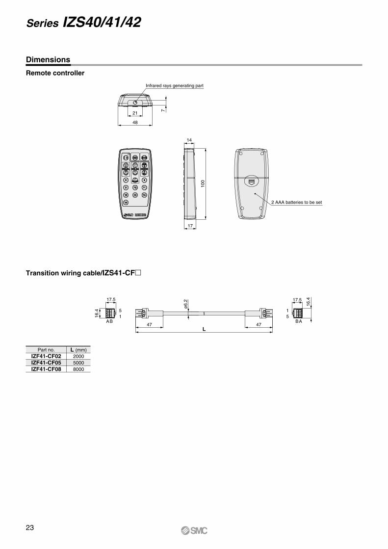
Dimensions
Remote controller
Transition wiring cable/IZS41-CF
Part no.200050008000
L (mm)IZF41-CF02IZF41-CF05IZF41-CF08
BA15
BA51
17.5
16.4
47L
47
ø6.
2 17.5
16.4
48
21
7
Infrared rays generating part
14
100
17
2 AAA batteries to be set
Series IZS40/41/42
23
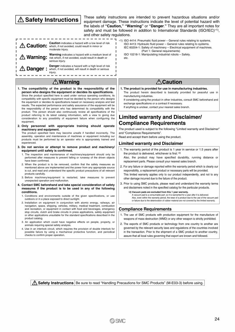
1. The compatibility of the product is the responsibility of the person who designs the equipment or decides its specifications.Since the product specified here is used under various operating conditions, its compatibility with specific equipment must be decided by the person who designs the equipment or decides its specifications based on necessary analysis and test results. The expected performance and safety assurance of the equipment will be the responsibility of the person who has determined its compatibility with the product. This person should also continuously review all specifications of the product referring to its latest catalog information, with a view to giving due consideration to any possibility of equipment failure when configuring the equipment.
2. Only personnel with appropriate training should operate machinery and equipment.The product specified here may become unsafe if handled incorrectly. The assembly, operation and maintenance of machines or equipment including our products must be performed by an operator who is appropriately trained and experienced.
3. Do not service or attempt to remove product and machinery/equipment until safety is confirmed.1. The inspection and maintenance of machinery/equipment should only be
performed after measures to prevent falling or runaway of the driven objects have been confirmed.
2. When the product is to be removed, confirm that the safety measures as mentioned above are implemented and the power from any appropriate source is cut, and read and understand the specific product precautions of all relevant products carefully.
3. Before machinery/equipment is restarted, take measures to prevent unexpected operation and malfunction.
4. Contact SMC beforehand and take special consideration of safety measures if the product is to be used in any of the following conditions. 1. Conditions and environments outside of the given specifications, or use
outdoors or in a place exposed to direct sunlight.2. Installation on equipment in conjunction with atomic energy, railways, air
navigation, space, shipping, vehicles, military, medical treatment, combustion and recreation, or equipment in contact with food and beverages, emergency stop circuits, clutch and brake circuits in press applications, safety equipment or other applications unsuitable for the standard specifications described in the product catalog.
3. An application which could have negative effects on people, property, or animals requiring special safety analysis.
4. Use in an interlock circuit, which requires the provision of double interlock for possible failure by using a mechanical protective function, and periodical checks to confirm proper operation.
Warning
Limited warranty and Disclaimer/Compliance Requirements The product used is subject to the following “Limited warranty and Disclaimer” and “Compliance Requirements”.Read and accept them before using the product.
1. The product is provided for use in manufacturing industries.The product herein described is basically provided for peaceful use in manufacturing industries. If considering using the product in other industries, consult SMC beforehand and exchange specifications or a contract if necessary. If anything is unclear, contact your nearest sales branch.
Caution
Limited warranty and Disclaimer1. The warranty period of the product is 1 year in service or 1.5 years after
the product is delivered, whichever is first.∗2)
Also, the product may have specified durability, running distance or replacement parts. Please consult your nearest sales branch.
2. For any failure or damage reported within the warranty period which is clearly our responsibility, a replacement product or necessary parts will be provided. This limited warranty applies only to our product independently, and not to any other damage incurred due to the failure of the product.
3. Prior to using SMC products, please read and understand the warranty terms and disclaimers noted in the specified catalog for the particular products.
∗2) Vacuum pads are excluded from this 1 year warranty.A vacuum pad is a consumable part, so it is warranted for a year after it is delivered. Also, even within the warranty period, the wear of a product due to the use of the vacuum pad or failure due to the deterioration of rubber material are not covered by the limited warranty.
Compliance Requirements1. The use of SMC products with production equipment for the manufacture of
weapons of mass destruction (WMD) or any other weapon is strictly prohibited.
2. The exports of SMC products or technology from one country to another are governed by the relevant security laws and regulations of the countries involved in the transaction. Prior to the shipment of a SMC product to another country, assure that all local rules governing that export are known and followed.
These safety instructions are intended to prevent hazardous situations and/or equipment damage. These instructions indicate the level of potential hazard with the labels of “Caution,” “Warning” or “Danger.” They are all important notes for safety and must be followed in addition to International Standards (ISO/IEC)∗1), and other safety regulations.
∗1) ISO 4414: Pneumatic fluid power – General rules relating to systems. ISO 4413: Hydraulic fluid power – General rules relating to systems. IEC 60204-1: Safety of machinery – Electrical equipment of machines. (Part 1: General requirements) ISO 10218-1: Manipulating industrial robots – Safety. etc.
Caution indicates a hazard with a low level of risk which, if not avoided, could result in minor or moderate injury.
Warning indicates a hazard with a medium level of risk which, if not avoided, could result in death or serious injury.
Caution:
Warning:
Danger :Danger indicates a hazard with a high level of risk which, if not avoided, will result in death or serious injury.
Safety Instructions
Safety Instructions Be sure to read “Handling Precautions for SMC Products” (M-E03-3) before using.
24
200 200 150 150
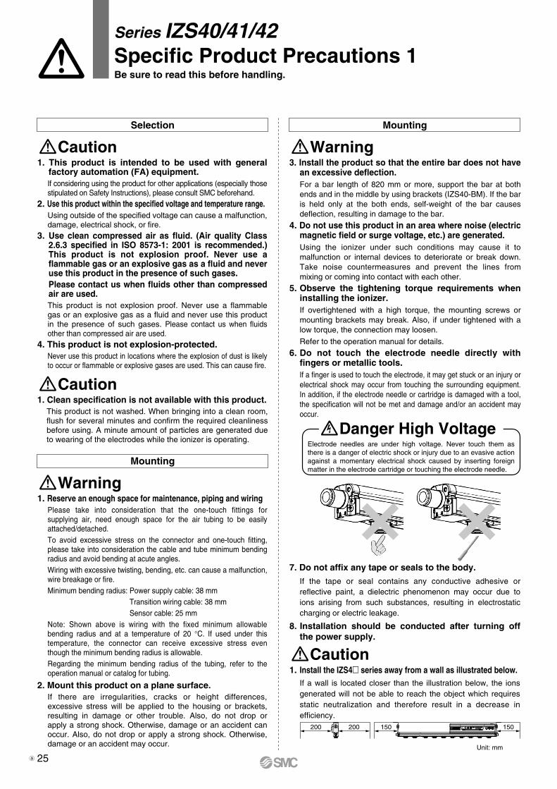
Electrode needles are under high voltage. Never touch them as there is a danger of electric shock or injury due to an evasive action against a momentary electrical shock caused by inserting foreign matter in the electrode cartridge or touching the electrode needle.
Series IZS40/41/42Specific Product Precautions 1Be sure to read this before handling.
Selection Mounting
Caution
Caution
Warning1. This product is intended to be used with general
factory automation (FA) equipment.If considering using the product for other applications (especially those stipulated on Safety Instructions), please consult SMC beforehand.
2. Use this product within the specified voltage and temperature range.Using outside of the specified voltage can cause a malfunction, damage, electrical shock, or fire.
3. Use clean compressed air as fluid. (Air quality Class 2.6.3 specified in ISO 8573-1: 2001 is recommended.) This product is not explosion proof. Never use a flammable gas or an explosive gas as a fluid and never use this product in the presence of such gases. Please contact us when fluids other than compressed air are used.This product is not explosion proof. Never use a flammable gas or an explosive gas as a fluid and never use this product in the presence of such gases. Please contact us when fluids other than compressed air are used.
4. This product is not explosion-protected.Never use this product in locations where the explosion of dust is likely to occur or flammable or explosive gases are used. This can cause fire.
1. Clean specification is not available with this product.This product is not washed. When bringing into a clean room, flush for several minutes and confirm the required cleanliness before using. A minute amount of particles are generated due to wearing of the electrodes while the ionizer is operating.
3. Install the product so that the entire bar does not have an excessive deflection.For a bar length of 820 mm or more, support the bar at both ends and in the middle by using brackets (IZS40-BM). If the bar is held only at the both ends, self-weight of the bar causes deflection, resulting in damage to the bar.
4. Do not use this product in an area where noise (electric magnetic field or surge voltage, etc.) are generated.Using the ionizer under such conditions may cause it to malfunction or internal devices to deteriorate or break down. Take noise countermeasures and prevent the lines from mixing or coming into contact with each other.
5. Observe the tightening torque requirements when installing the ionizer.If overtightened with a high torque, the mounting screws or mounting brackets may break. Also, if under tightened with a low torque, the connection may loosen.
Refer to the operation manual for details.
6. Do not touch the electrode needle directly with fingers or metallic tools.If a finger is used to touch the electrode, it may get stuck or an injury or electrical shock may occur from touching the surrounding equipment. In addition, if the electrode needle or cartridge is damaged with a tool, the specification will not be met and damage and/or an accident may occur.
Mounting
Warning1. Reserve an enough space for maintenance, piping and wiring
Please take into consideration that the one-touch fittings for supplying air, need enough space for the air tubing to be easily attached/detached.To avoid excessive stress on the connector and one-touch fitting, please take into consideration the cable and tube minimum bending radius and avoid bending at acute angles.Wiring with excessive twisting, bending, etc. can cause a malfunction, wire breakage or fire.Minimum bending radius: Power supply cable: 38 mm Transition wiring cable: 38 mm Sensor cable: 25 mmNote: Shown above is wiring with the fixed minimum allowable bending radius and at a temperature of 20 °C. If used under this temperature, the connector can receive excessive stress even though the minimum bending radius is allowable.Regarding the minimum bending radius of the tubing, refer to the operation manual or catalog for tubing.
2. Mount this product on a plane surface.If there are irregularities, cracks or height differences, excessive stress will be applied to the housing or brackets, resulting in damage or other trouble. Also, do not drop or apply a strong shock. Otherwise, damage or an accident can occur. Also, do not drop or apply a strong shock. Otherwise, damage or an accident may occur.
7. Do not affix any tape or seals to the body.
If the tape or seal contains any conductive adhesive or reflective paint, a dielectric phenomenon may occur due to ions arising from such substances, resulting in electrostatic charging or electric leakage.
8. Installation should be conducted after turning off the power supply.
Unit: mm
Caution1. Install the IZS4 series away from a wall as illustrated below.
If a wall is located closer than the illustration below, the ions generated will not be able to reach the object which requires static neutralization and therefore result in a decrease in efficiency.
Danger High Voltage
25a
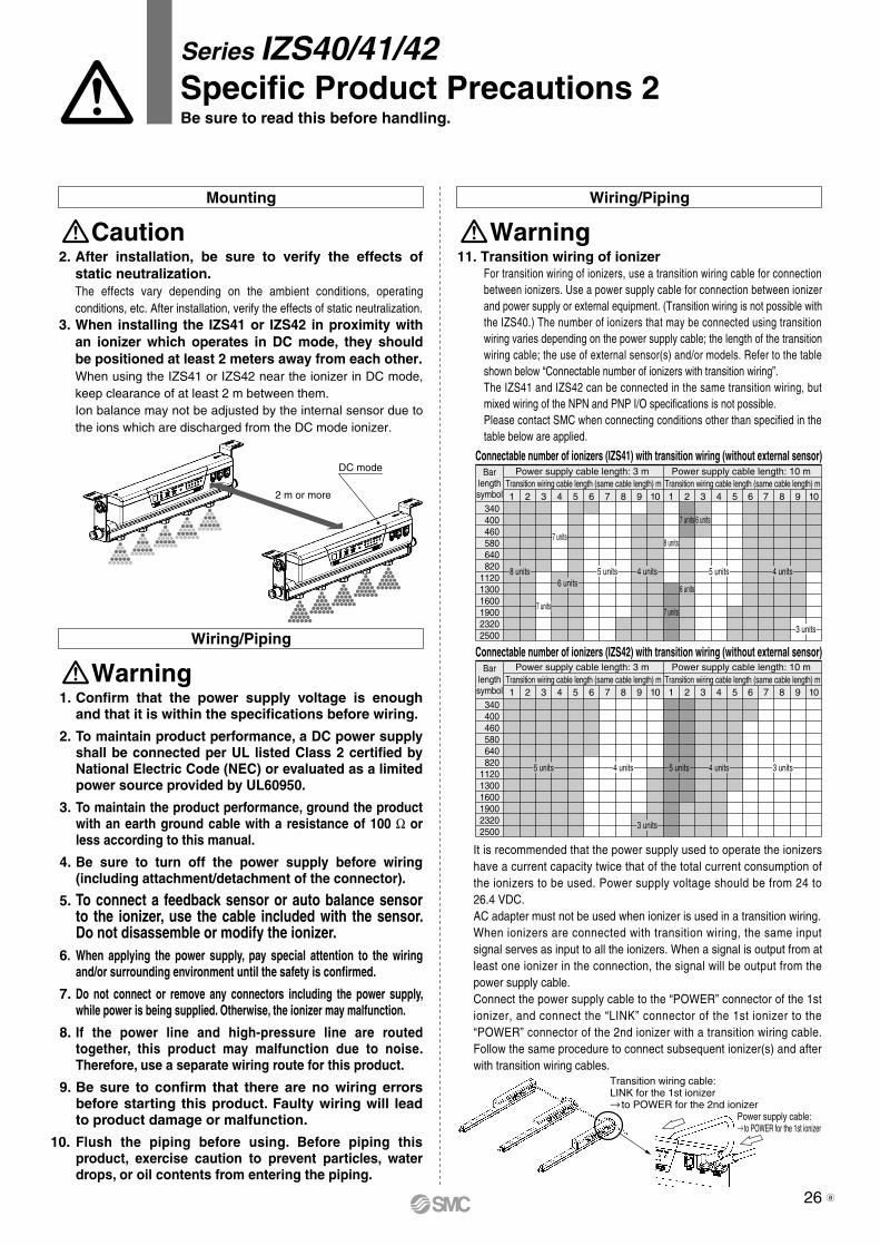
Power supply cable:→ to POWER for the 1st ionizer
Transition wiring cable:LINK for the 1st ionizer→ to POWER for the 2nd ionizer
2 m or more
DC mode
Series IZS40/41/42Specific Product Precautions 2Be sure to read this before handling.
Mounting Wiring/Piping
Caution Warning11. Transition wiring of ionizer
For transition wiring of ionizers, use a transition wiring cable for connection between ionizers. Use a power supply cable for connection between ionizer and power supply or external equipment. (Transition wiring is not possible with the IZS40.) The number of ionizers that may be connected using transition wiring varies depending on the power supply cable; the length of the transition wiring cable; the use of external sensor(s) and/or models. Refer to the table shown below “Connectable number of ionizers with transition wiring”.The IZS41 and IZS42 can be connected in the same transition wiring, but mixed wiring of the NPN and PNP I/O specifications is not possible.Please contact SMC when connecting conditions other than specified in the table below are applied.
It is recommended that the power supply used to operate the ionizers have a current capacity twice that of the total current consumption of the ionizers to be used. Power supply voltage should be from 24 to 26.4 VDC.AC adapter must not be used when ionizer is used in a transition wiring.When ionizers are connected with transition wiring, the same input signal serves as input to all the ionizers. When a signal is output from at least one ionizer in the connection, the signal will be output from the power supply cable.Connect the power supply cable to the “POWER” connector of the 1st ionizer, and connect the “LINK” connector of the 1st ionizer to the “POWER” connector of the 2nd ionizer with a transition wiring cable. Follow the same procedure to connect subsequent ionizer(s) and after with transition wiring cables.
2. After installation, be sure to verify the effects of static neutralization.The effects vary depending on the ambient conditions, operating conditions, etc. After installation, verify the effects of static neutralization.
3. When installing the IZS41 or IZS42 in proximity with an ionizer which operates in DC mode, they should be positioned at least 2 meters away from each other.When using the IZS41 or IZS42 near the ionizer in DC mode, keep clearance of at least 2 m between them.Ion balance may not be adjusted by the internal sensor due to the ions which are discharged from the DC mode ionizer.
Wiring/Piping
Warning1. Confirm that the power supply voltage is enough
and that it is within the specifications before wiring.
2. To maintain product performance, a DC power supply shall be connected per UL listed Class 2 certified by National Electric Code (NEC) or evaluated as a limited power source provided by UL60950.
3. To maintain the product performance, ground the product with an earth ground cable with a resistance of 100 Ω or less according to this manual.
4. Be sure to turn off the power supply before wiring (including attachment/detachment of the connector).
5. To connect a feedback sensor or auto balance sensor to the ionizer, use the cable included with the sensor. Do not disassemble or modify the ionizer.
6. When applying the power supply, pay special attention to the wiring and/or surrounding environment until the safety is confirmed.
7. Do not connect or remove any connectors including the power supply, while power is being supplied. Otherwise, the ionizer may malfunction.
8. If the power line and high-pressure line are routed together, this product may malfunction due to noise. Therefore, use a separate wiring route for this product.
9. Be sure to confirm that there are no wiring errors before starting this product. Faulty wiring will lead to product damage or malfunction.
10. Flush the piping before using. Before piping this product, exercise caution to prevent particles, water drops, or oil contents from entering the piping.
Barlengthsymbol
340 400 460 580 640 820112013001600190023202500
Connectable number of ionizers (IZS41) with transition wiring (without external sensor)
Barlengthsymbol
340 400 460 580 640 820112013001600190023202500
Connectable number of ionizers (IZS42) with transition wiring (without external sensor)
8 units 4 units6 units
5 units 5 units 4 units
3 units
7 units
7 units8 units
7 units 6 units
6 units
7 units
5 units
3 units
4 units 4 units5 units 3 units
1 2 3 4 5 6 7 8 9 10Transition wiring cable length (same cable length) m
Power supply cable length: 3 m
1 2 3 4 5 6 7 8 9 10Transition wiring cable length (same cable length) m
Power supply cable length: 10 m
1 2 3 4 5 6 7 8 9 10Transition wiring cable length (same cable length) m
Power supply cable length: 3 m
1 2 3 4 5 6 7 8 9 10Transition wiring cable length (same cable length) m
Power supply cable length: 10 m
26 a
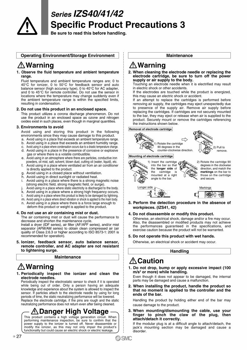
1) Rotate the cartridge90 degrees in thecounter-clockwise direction.
2) Pull toremove.
Longer side Markings
Removal of electrode cartridge
Mounting of electrode cartridge
1) Insert the cartridge into the bar so that the longer side of the cartridge is mounted at a right angle to the bar.
2) Rotate the cartridge 90 degrees in the clockwise direction, and match the markings on the bar to those on the cartridge and secure.
Series IZS40/41/42Specific Product Precautions 3Be sure to read this before handling.
Operating Environment/Storage Environment Maintenance
Warning Warning1. Observe the fluid temperature and ambient temperature
range.Fluid temperature and ambient temperature ranges are; 0 to 40°C for ionizer, 0 to 50°C for feedback sensor and auto balance sensor (high accuracy type), 0 to 40°C for AC adapter, and 0 to 45°C for remote controller. Do not use the sensor in locations where the temperature may change suddenly even if the ambient temperature range is within the specified limits, resulting in condensation.
2. Do not use this product in an enclosed space.This product utilizes a corona discharge phenomenon. Do not use the product in an enclosed space as ozone and nitrogen oxides exist in such places, even though in marginal quantities.
3. Environments to avoidAvoid using and storing this product in the following environments since they may cause damage to this product. a. Avoid using in a place that exceeds an ambient temperature range.b. Avoid using in a place that exceeds an ambient humidity range.c. Avoid using in a place where condensation occurs due to a drastic temperature change.d. Avoid using in a place in the presence of corrosive or explosive gas or where there is a volatile combustible.e. Avoid using in an atmosphere where there are particles, conductive iron powders, oil mist, salt, solvent, blown dust, cutting oil (water, liquid), etc.f. Avoid using in a place where ventilated air from an air conditioner is directly applied to the product.g. Avoid using in a closed place without ventilation.h. Avoid using in direct sunlight or radiated heat.i. Avoid using in a place where there is a strong magnetic noise (strong electric field, strong magnetic field, or surge).j. Avoid using in a place where static electricity is discharged to the body.k. Avoid using in a place where a strong high frequency occurs.l. Avoid using in a place where this product is likely to be damaged by lightning.m. Avoid using in a place where direct vibration or shock is applied to the main body.n. Avoid using in a place where there is a force large enough to deform this product or weight is applied to the product.
4. Do not use an air containing mist or dust.The air containing mist or dust will cause the performance to decrease and shorten the maintenance cycle.Install a dryer (IDF series), air filter (AF/AFF series), and/or mist separator (AFM/AM series) to obtain clean compressed air (air quality of Class 2.6.3 or higher according to ISO 8573-1: 2001 is recommended for operation).
5. Ionizer, feedback sensor, auto balance sensor, remote controller, and AC adapter are not resistant to lightening surge.
2. When cleaning the electrode needle or replacing the electrode cartridge, be sure to turn off the power supply or air supply to the body.Touching an electrode needle when it is electrified may result in electric shock or other accidents.If the electrodes are touched while the product is energized, this may cause an electric shock or accident.If an attempt to replace the cartridges is performed before removing air supply, the cartridges may eject unexpectedly due to presence of the supply air. Remove air supply before replacing the cartridges. If cartridges are not securely mounted to the bar, they may eject or release when air is supplied to the product. Securely mount or remove the cartridges referencing the instructions shown below.
3. Perform the detection procedure in the absence of workpieces. (IZS41, 42)
4. Do not disassemble or modify this product.Otherwise, an electrical shock, damage and/or a fire may occur. Also, the disassembled or modified products may not achieve the performances guaranteed in the specifications, and exercise caution because the product will not be warranted.
5. Do not operate this product with wet hands.Otherwise, an electrical shock or accident may occur.
Handling
Caution1. Do not drop, bump or apply excessive impact (100
m/s2 or more) while handling.Even though it does not appear to be damaged, the internal parts may be damaged and cause a malfunction.
2. When installing the product, handle the product so that no moment is applied to the controller and the ends of the bar.Handling the product by holding either end of the bar may cause damage to the product.
3. When mounting/dismounting the cable, use your finger to pinch the claw of the plug, then attach/detach it correctly.If the modular plug is at a difficult angle to attach/detach, the jack’s mounting section may be damaged and cause a disorder.
Maintenance
Warning1. Periodically inspect the ionizer and clean the
electrode needles.Periodically inspect the electrostatic sensor to check if it is operated while being out of order. Only a person having an adequate knowledge and experience about the system is allowed to inspect the sensor. If particles attach to the electrode needle by using for long periods of time, the static neutralizing performance will be lowered.Replace the electrode cartridge, if the pins are rough and the static neutralizing performance does not return even after being cleaned.
This product contains a high voltage generation circuit. When performing maintenance inspection, be sure to confirm that the power supply to the ionizer is turned off. Never disassemble or modify the ionizer, as this may not only impair the product’s functionality but could cause an electric shock or electric leakage.
Danger High Voltage
27a

28

29
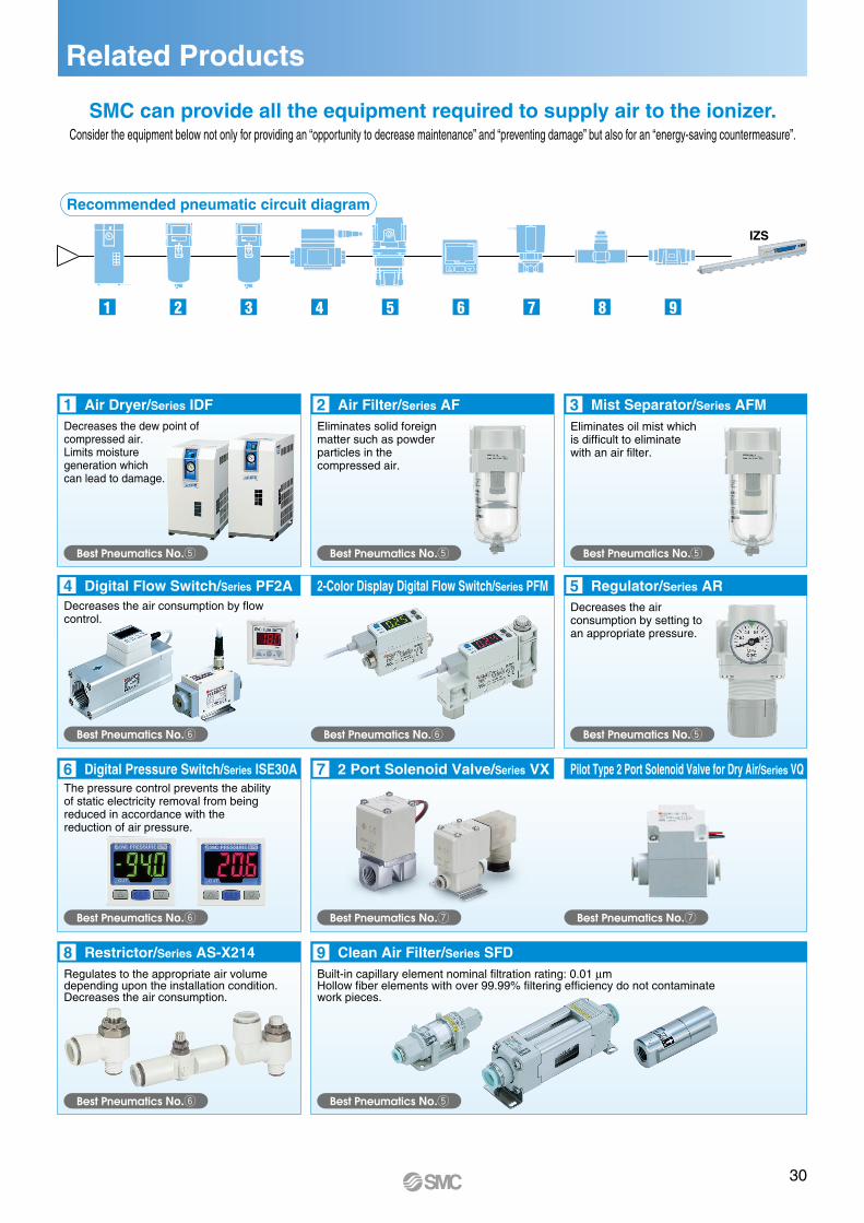
Related Products
1 2 3 4 5 6 7 8 9
IZS
4
9
6 7
8
5
SMC can provide all the equipment required to supply air to the ionizer.Consider the equipment below not only for providing an “opportunity to decrease maintenance” and “preventing damage” but also for an “energy-saving countermeasure”.
Air Dryer/Series IDFDecreases the dew point of compressed air. Limits moisture generation which can lead to damage.
Decreases the air consumption by flowcontrol.
Digital Flow Switch/Series PF2A 2-Color Display Digital Flow Switch/Series PFM
Pilot Type 2 Port Solenoid Valve for Dry Air/Series VQ
Regulator/Series AR
Digital Pressure Switch/Series ISE30AThe pressure control prevents the abilityof static electricity removal from beingreduced in accordance with thereduction of air pressure.
2 Port Solenoid Valve/Series VX
Restrictor/Series AS-X214Regulates to the appropriate air volumedepending upon the installation condition.Decreases the air consumption.
Clean Air Filter/Series SFDBuilt-in capillary element nominal filtration rating: 0.01 µmHollow fiber elements with over 99.99% filtering efficiency do not contaminatework pieces.
1 2 3Air Filter/Series AF Mist Separator/Series AFM
Decreases the airconsumption by setting toan appropriate pressure.
Eliminates solid foreignmatter such as powderparticles in thecompressed air.
Eliminates oil mist whichis difficult to eliminatewith an air filter.
Best Pneumatics No.t Best Pneumatics No.t Best Pneumatics No.t
Best Pneumatics No.tBest Pneumatics No.yBest Pneumatics No.y
Best Pneumatics No.y Best Pneumatics No.u Best Pneumatics No.u
Best Pneumatics No.tBest Pneumatics No.y
Recommended pneumatic circuit diagram
30
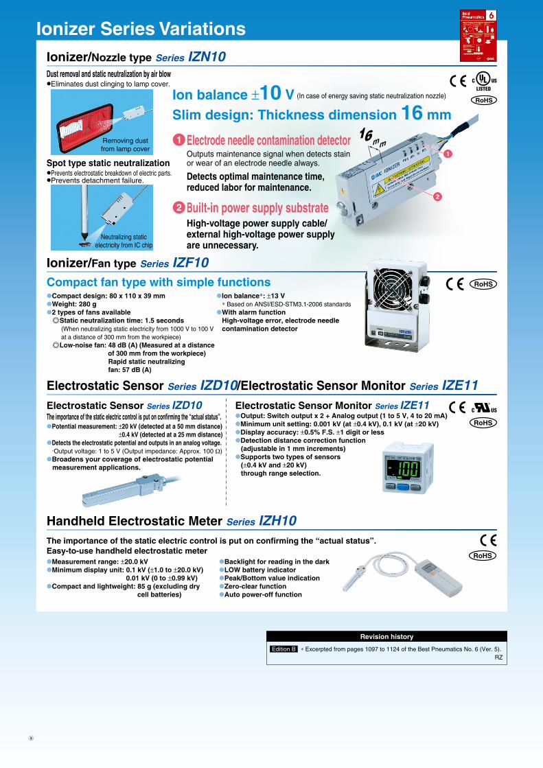
RoHS
®
RoHS
RoHS
RoHS
∗ Excerpted from pages 1097 to 1124 of the Best Pneumatics No. 6 (Ver. 5). RZ
Revision history
Edition B
Ionizer Series VariationsIonizer/Nozzle type Series IZN10
Ionizer/Fan type Series IZF10
16mm
2
1
Removing dustfrom lamp cover
Neutralizing staticelectricity from IC chip
Eliminates dust clinging to lamp cover.Dust removal and static neutralization by air blow
Prevents electrostatic breakdown of electric parts.Prevents detachment failure.
Spot type static neutralizationOutputs maintenance signal when detects stainor wear of an electrode needle always.
Detects optimal maintenance time,reduced labor for maintenance.
High-voltage power supply cable/external high-voltage power supplyare unnecessary.
Electrode needle contamination detector
Built-in power supply substrate
Ion balance ±10 VSlim design: Thickness dimension 16 mm
(In case of energy saving static neutralization nozzle)
1
2
Compact fan type with simple functionsCompact design: 80 x 110 x 39 mmWeight: 280 g2 types of fans available
Static neutralization time: 1.5 seconds(When neutralizing static electricity from 1000 V to 100 Vat a distance of 300 mm from the workpiece)
Low-noise fan: 48 dB (A) (Measured at a distance of 300 mm from the workpiece)
Rapid static neutralizingfan: 57 dB (A)
Ion balance∗: ±13 V∗ Based on ANSI/ESD-STM3.1-2006 standards
With alarm functionHigh-voltage error, electrode needlecontamination detector
Handheld Electrostatic Meter Series IZH10
Measurement range: ±20.0 kVMinimum display unit: 0.1 kV (±1.0 to ±20.0 kV)
0.01 kV (0 to ±0.99 kV)Compact and lightweight: 85 g (excluding dry cell batteries)
Backlight for reading in the darkLOW battery indicatorPeak/Bottom value indicationZero-clear functionAuto power-off function
The importance of the static electric control is put on confirming the “actual status”.Easy-to-use handheld electrostatic meter
Electrostatic Sensor Series IZD10/Electrostatic Sensor Monitor Series IZE11Electrostatic Sensor Series IZD10The importance of the static electric control is put on confirming the “actual status”.Potential measurement: ±20 kV (detected at a 50 mm distance)
±0.4 kV (detected at a 25 mm distance)Detects the electrostatic potential and outputs in an analog voltage.
·Output voltage: 1 to 5 V (Output impedance: Approx. 100 Ω)Broadens your coverage of electrostatic potential measurement applications.
Electrostatic Sensor Monitor Series IZE11Output: Switch output x 2 + Analog output (1 to 5 V, 4 to 20 mA)Minimum unit setting: 0.001 kV (at ±0.4 kV), 0.1 kV (at ±20 kV)Display accuracy: ±0.5% F.S. ±1 digit or lessDetection distance correction function (adjustable in 1 mm increments)Supports two types of sensors (±0.4 kV and ±20 kV) through range selection.
a