Embed Size (px)
Citation preview
MAN-BIOPUREHX2 (rev. E)
Biolab Equipment Ltd. o/a Mar Cor Purification
BioPure HX2® SYSTEM
System Operation Manual
Unit may not appear exactly as shown
MAN-BIOPUREHX2 (rev. E) page 2 of 141
BioPure HX2® System
INTENDED USE
CANADA
This device is intended to remove organic, inorganic, and microbial contaminants from water that is used to dilute dialysis concentrate to form dialysate, and to produce purified water for dialyzer reprocessing and equipment rinse and sterilization.
CAUTION: When used as a Medical Device, federal law restricts this device to sale by and or on the order of a physician.
UNITED STATES OF AMERICA
The BioPure HX2 Reverse Osmosis water purification system is designed to purify pre-treated water using reverse osmosis for making dialysate for hemodialysis applications. The device is intended to be a component in a complete water purification system. It must be preceded by pre-treatment devices, and may need to be followed by post-treatment devices as well to meet current AAMI and Federal (U.S.) standards. BioPure HX2 is intended for use in water rooms in a hospital, clinic, or dialysis center. The device includes an integrated heat disinfection process.
The BioPure HX2 is available two different double pass configurations that supply 5 gallons per minute (gpm) and 11 gpm. Version HX2P-05 is a double pass triple membrane RO that produces up to 5 gpm of product water. Version HX2P-11 is a double pass six membrane RO that produces up to 11 gpm of product water.
CAUTION: When used as a Medical Device, federal law restricts this device to sale by and or on the order of a physician.
This manual is intended to provide instructions to operate and provide basic maintenance instructions for the BioPure HX2® System.

MAN-BIOPUREHX2 (rev. E) page 3 of 141
BioPure HX2® System
BIOLAB SERIAL #:
DEVICE IDENTIFIER:
DATE MANUFACTURED:
MAN-BIOPUREHX2 (rev. E) page 4 of 141
BioPure HX2® System
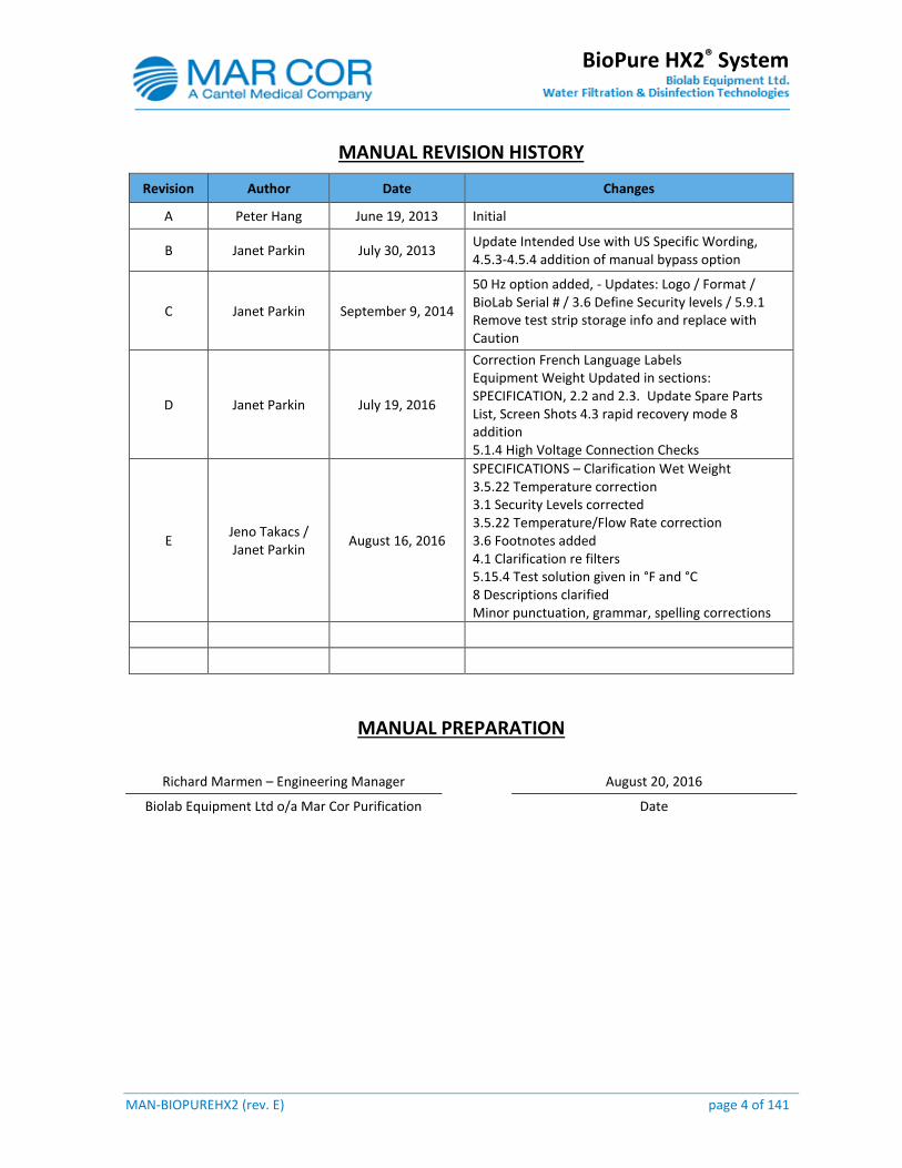
MANUAL REVISION HISTORY
Revision Author Date Changes
A Peter Hang June 19, 2013 Initial
B Janet Parkin July 30, 2013 Update Intended Use with US Specific Wording, 4.5.3-4.5.4 addition of manual bypass option
C Janet Parkin September 9, 2014
50 Hz option added, - Updates: Logo / Format / BioLab Serial # / 3.6 Define Security levels / 5.9.1 Remove test strip storage info and replace with Caution
D Janet Parkin July 19, 2016
Correction French Language Labels Equipment Weight Updated in sections: SPECIFICATION, 2.2 and 2.3. Update Spare Parts List, Screen Shots 4.3 rapid recovery mode 8 addition 5.1.4 High Voltage Connection Checks
E Jeno Takacs / Janet Parkin
August 16, 2016
SPECIFICATIONS – Clarification Wet Weight 3.5.22 Temperature correction 3.1 Security Levels corrected 3.5.22 Temperature/Flow Rate correction 3.6 Footnotes added 4.1 Clarification re filters 5.15.4 Test solution given in °F and °C 8 Descriptions clarified Minor punctuation, grammar, spelling corrections
MANUAL PREPARATION
Richard Marmen – Engineering Manager August 20, 2016
Biolab Equipment Ltd o/a Mar Cor Purification Date

MAN-BIOPUREHX2 (rev. E) page 5 of 141
BioPure HX2® System
TABLE OF CONTENTS
INTENDED USE .................................................................................................................................................. 2
SAFETY .............................................................................................................................................................. 8
DEFINITIONS ..................................................................................................................................................... 8
LABELS .............................................................................................................................................................. 9
SPECIFICATIONS .............................................................................................................................................. 10
GENERAL PRECAUTIONS ................................................................................................................................. 12
1.0 BIOPURE HX2® SYSTEM OVERVIEW ....................................................................................................... 15
2.0 INSTALLATION REQUIREMENTS ............................................................................................................. 17
3.0 SYSTEM CONTROL OVERVIEW ............................................................................................................... 18
SECURITY .................................................................................................................................................. 18 ALARM MANAGEMENT ............................................................................................................................ 19 3.2.1 Main Control Panel Status and Alarm Indicator Function .............................................................. 19 REMOTE NURSE`S STATION MONITOR AND ALARM INDICATOR ............................................................. 20 USB DRIVE AND PRINTER (OPTIONAL) ......................................................................................................... 20 THE HMI DISPLAY NAVIGATION ................................................................................................................ 21 3.5.1 Valve Indicator Positions ................................................................................................................ 22 3.5.2 Screen Layout.................................................................................................................................. 23 3.5.3 Screen Selection .............................................................................................................................. 25 3.5.4 Main Screen .................................................................................................................................... 27 3.5.5 System Mode Control...................................................................................................................... 28 3.5.6 Pre-treatment ................................................................................................................................. 29 3.5.7 Break Tank ...................................................................................................................................... 30 3.5.8 Heater ............................................................................................................................................. 31 3.5.9 RO Feed ........................................................................................................................................... 32 3.5.10 1st Pass Pump ............................................................................................................................. 33 3.5.11 1st Pass RO .................................................................................................................................. 34 3.5.12 2nd Pass Pump ............................................................................................................................ 35 3.5.13 2nd Pass RO ................................................................................................................................. 36 3.5.14 Overview .................................................................................................................................... 37 3.5.15 Status ......................................................................................................................................... 38 3.5.16 Loop Filter (Optional) ................................................................................................................. 40 3.5.17 Active Alarm ............................................................................................................................... 41 3.5.18 Alarm History ............................................................................................................................. 42 3.5.19 Heat Sanitization History ........................................................................................................... 43 3.5.20 Chemical Cleaning History ......................................................................................................... 44 3.5.21 Sequence History ........................................................................................................................ 45 3.5.22 Setpoint 1 ................................................................................................................................... 46 3.5.23 Setpoint 2 ................................................................................................................................... 49 3.5.24 Setpoint 3 ................................................................................................................................... 52 3.5.25 Setpoint 4 ................................................................................................................................... 55 3.5.26 Setpoint 5 ................................................................................................................................... 57 3.5.27 Production and Heat Sanitization Scheduler .............................................................................. 61 3.5.28 Program Revision ....................................................................................................................... 62
MAN-BIOPUREHX2 (rev. E) page 6 of 141
BioPure HX2® System
3.5.29 Time and Date ............................................................................................................................ 63 3.5.30 Users Password .......................................................................................................................... 64 3.5.31 Reset User Password .................................................................................................................. 65 3.5.32 Misc. Devices .............................................................................................................................. 66 3.5.33 Data Logging .............................................................................................................................. 67 3.5.34 Remote Nurses Station............................................................................................................... 68 SETPOINT REFERENCE TABLE .................................................................................................................... 69
4.0 SYSTEM OPERATION .............................................................................................................................. 73
SYSTEM VERIFICATION BEFORE STARTING UP .......................................................................................... 73 PANEL START-UP AND SHUT DOWN ......................................................................................................... 73 4.2.1 Panel Start-up ................................................................................................................................. 73 4.2.2 Panel Shut Down ............................................................................................................................. 73 MANUAL START-UP / SHUT DOWN PROCEDURE ...................................................................................... 74 HEAT SANITIZATION ................................................................................................................................. 74 4.4.1 Auto Heat Sanitization .................................................................................................................... 76 4.4.2 Manual Heat Sanitization ............................................................................................................... 76 4.4.3 Loop and Points of use Heat Sanitization ....................................................................................... 76 EMERGENCY BY-PASS OPERATION ........................................................................................................... 77 4.5.1 1st Pass By-Pass Operation ............................................................................................................. 77 4.5.2 2nd Pass By-Pass Operation ........................................................................................................... 78 4.5.3 Manual By-pass Operation ............................................................................................................. 78 4.5.4 Conductivity Transmitter Manual By-pass Setpoint Change .......................................................... 79 RO PERFORMANCE OVERVIEW................................................................................................................. 80 4.6.1 System Performance ....................................................................................................................... 80 4.6.2 Effects of Temperature on System Performance ............................................................................ 82 4.6.3 High Recovery Operation ................................................................................................................ 82
5.0 MAINTENANCE ...................................................................................................................................... 84
MAINTENANCE REQUIREMENTS .............................................................................................................. 84 5.1.1 RO System Shutdown Procedure ..................................................................................................... 85 5.1.2 RO Pre-filter Cartridge Replacement Procedure ............................................................................. 85 5.1.3 Log Sheet ........................................................................................................................................ 86 5.1.4 Service Schedule.............................................................................................................................. 88 5.1.5 Alarm ∕ Alert Log Sheet ................................................................................................................... 89 CLEANING OVERVIEW .............................................................................................................................. 90 SANITIZATION OVERVIEW ........................................................................................................................ 91 CHEMICAL SELECTION AND USE OF CLEANING CHEMICALS ..................................................................... 93 GENERAL PRECAUTIONS IN CLEANING CHEMICAL SELECTION AND USAGE ............................................. 93 CLEANING/SANITIZATION FREQUENCY .................................................................................................... 95 RO CLEANING/SANITIZATION CHEMICALS ............................................................................................... 95 RO CLEANING/SANITIZATION CHEMICALS CONCENTRATIONS ................................................................ 95 NEUTRALIZING CLEANING/SANITIZATION SOLUTIONS ............................................................................ 96
MINNCARE® DISINFECTANT USE.......................................................................................................... 96 5.10.1 MINNCARE® Test Strip Overview ............................................................................................... 99 5.10.2 Test Strip Instruction .................................................................................................................. 99
SEMI-AUTOMATIC CHEMICAL CLEANING AND SANITIZATION .......................................................... 100 5.11.1 Chemical Cleaning and Sanitization Preparation ..................................................................... 101
1ST PASS CHEMICAL CLEANING / SANITIZATION PROCEDURE ........................................................... 101 2ND PASS CHEMICAL CLEANING / SANITIZATION PROCEDURE .......................................................... 103 LOOP CHEMICAL CLEANING / SANITIZATION PROCEDURE ................................................................ 105
MAN-BIOPUREHX2 (rev. E) page 7 of 141
BioPure HX2® System
SERVICE / REPLACEMENT PROCEDURES FOR SYSTEM COMPONENTS ............................................... 107 5.15.1 RO Pre-filter cartridge replacement Procedure ........................................................................ 107 5.15.2 Loop filter Cartridge Replacement (Optional Component) ...................................................... 108 5.15.3 Compressor .............................................................................................................................. 109 5.15.4 Conductivity Transmitter Calibration Procedure ...................................................................... 112
6.0 SYSTEM TROUBLESHOOTING ............................................................................................................... 117
7.0 SYSTEM STATUS MESSAGES ................................................................................................................. 134
8.0 SPARE PARTS LIST ................................................................................................................................ 137
9.0 GENERAL LIMITED WARRANTY ............................................................................................................ 140
CONTACT INFORMATION ....................................................................................................................... 140
MAN-BIOPUREHX2 (rev. E) page 8 of 141
BioPure HX2® System
SAFETY
This Manual describes procedures necessary to operate and maintain the BioPure HX2® system. It may make references to the Component Manuals of other manufacturers.
Please read and follow the instructions in this manual carefully to operate the RO system. Pay particular attention to all danger and caution statements to avoid serious injury to the operator and damage to the system.
This equipment is approved by regulatory agencies. Changes to the design and substitution of components are performed only under design controls and shall be documented. Changes without design controls are in contravention to regulation(s).
Operation of this system outside of its intended use and/or without adequate pre-treatment/post-treatment that meets ISO 13959-11 standard guidelines is not allowed and is in contravention to regulation(s).
DEFINITIONS
WARNING Indicates a potentially hazardous situation which, if not avoided, could result in death or serious personal injury.
CAUTION Indicates a potentially hazardous situation which, if not avoided, could result in minor or moderate personal injury or possible damage to the system.
NOTE Information that requires special emphasis.
MAN-BIOPUREHX2 (rev. E) page 9 of 141
BioPure HX2® System
LABELS
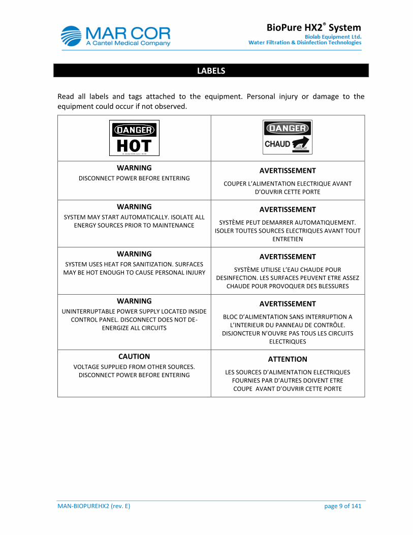
Read all labels and tags attached to the equipment. Personal injury or damage to the equipment could occur if not observed.
WARNING DISCONNECT POWER BEFORE ENTERING
AVERTISSEMENT
COUPER L’ALIMENTATION ELECTRIQUE AVANT D’OUVRIR CETTE PORTE
WARNING SYSTEM MAY START AUTOMATICALLY. ISOLATE ALL
ENERGY SOURCES PRIOR TO MAINTENANCE
AVERTISSEMENT
SYSTÈME PEUT DEMARRER AUTOMATIQUEMENT. ISOLER TOUTES SOURCES ELECTRIQUES AVANT TOUT
ENTRETIEN
WARNING SYSTEM USES HEAT FOR SANITIZATION. SURFACES
MAY BE HOT ENOUGH TO CAUSE PERSONAL INJURY
AVERTISSEMENT
SYSTÈME UTILISE L’EAU CHAUDE POUR DESINFECTION. LES SURFACES PEUVENT ETRE ASSEZ
CHAUDE POUR PROVOQUER DES BLESSURES
WARNING UNINTERRUPTABLE POWER SUPPLY LOCATED INSIDE
CONTROL PANEL. DISCONNECT DOES NOT DE-ENERGIZE ALL CIRCUITS
AVERTISSEMENT
BLOC D’ALIMENTATION SANS INTERRUPTION A L’INTERIEUR DU PANNEAU DE CONTRÔLE.
DISJONCTEUR N’OUVRE PAS TOUS LES CIRCUITS ELECTRIQUES
CAUTION VOLTAGE SUPPLIED FROM OTHER SOURCES.
DISCONNECT POWER BEFORE ENTERING
ATTENTION
LES SOURCES D’ALIMENTATION ELECTRIQUES FOURNIES PAR D’AUTRES DOIVENT ETRE COUPE AVANT D’OUVRIR CETTE PORTE
MAN-BIOPUREHX2 (rev. E) page 10 of 141
BioPure HX2® System
SPECIFICATIONS
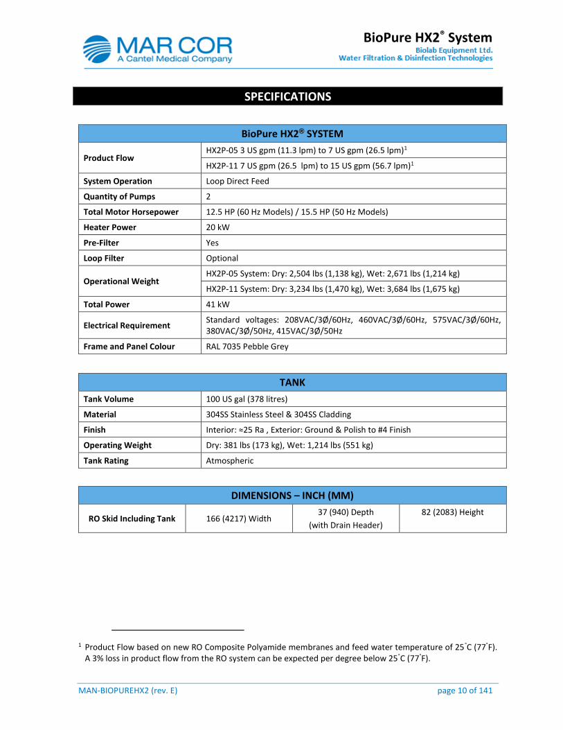
BioPure HX2® SYSTEM
Product Flow HX2P-05 3 US gpm (11.3 lpm) to 7 US gpm (26.5 lpm)1
HX2P-11 7 US gpm (26.5 lpm) to 15 US gpm (56.7 lpm)1
System Operation Loop Direct Feed
Quantity of Pumps 2
Total Motor Horsepower 12.5 HP (60 Hz Models) / 15.5 HP (50 Hz Models)
Heater Power 20 kW
Pre-Filter Yes
Loop Filter Optional
Operational Weight HX2P-05 System: Dry: 2,504 lbs (1,138 kg), Wet: 2,671 lbs (1,214 kg)
HX2P-11 System: Dry: 3,234 lbs (1,470 kg), Wet: 3,684 lbs (1,675 kg)
Total Power 41 kW
Electrical Requirement Standard voltages: 208VAC/3Ø/60Hz, 460VAC/3Ø/60Hz, 575VAC/3Ø/60Hz, 380VAC/3Ø/50Hz, 415VAC/3Ø/50Hz
Frame and Panel Colour RAL 7035 Pebble Grey
TANK
Tank Volume 100 US gal (378 litres)
Material 304SS Stainless Steel & 304SS Cladding
Finish Interior: ≈25 Ra , Exterior: Ground & Polish to #4 Finish
Operating Weight Dry: 381 lbs (173 kg), Wet: 1,214 lbs (551 kg)
Tank Rating Atmospheric
DIMENSIONS – INCH (MM)
RO Skid Including Tank 166 (4217) Width 37 (940) Depth
(with Drain Header)
82 (2083) Height
1 Product Flow based on new RO Composite Polyamide membranes and feed water temperature of 25°C (77°F). A 3% loss in product flow from the RO system can be expected per degree below 25°C (77°F).
MAN-BIOPUREHX2 (rev. E) page 11 of 141
BioPure HX2® System
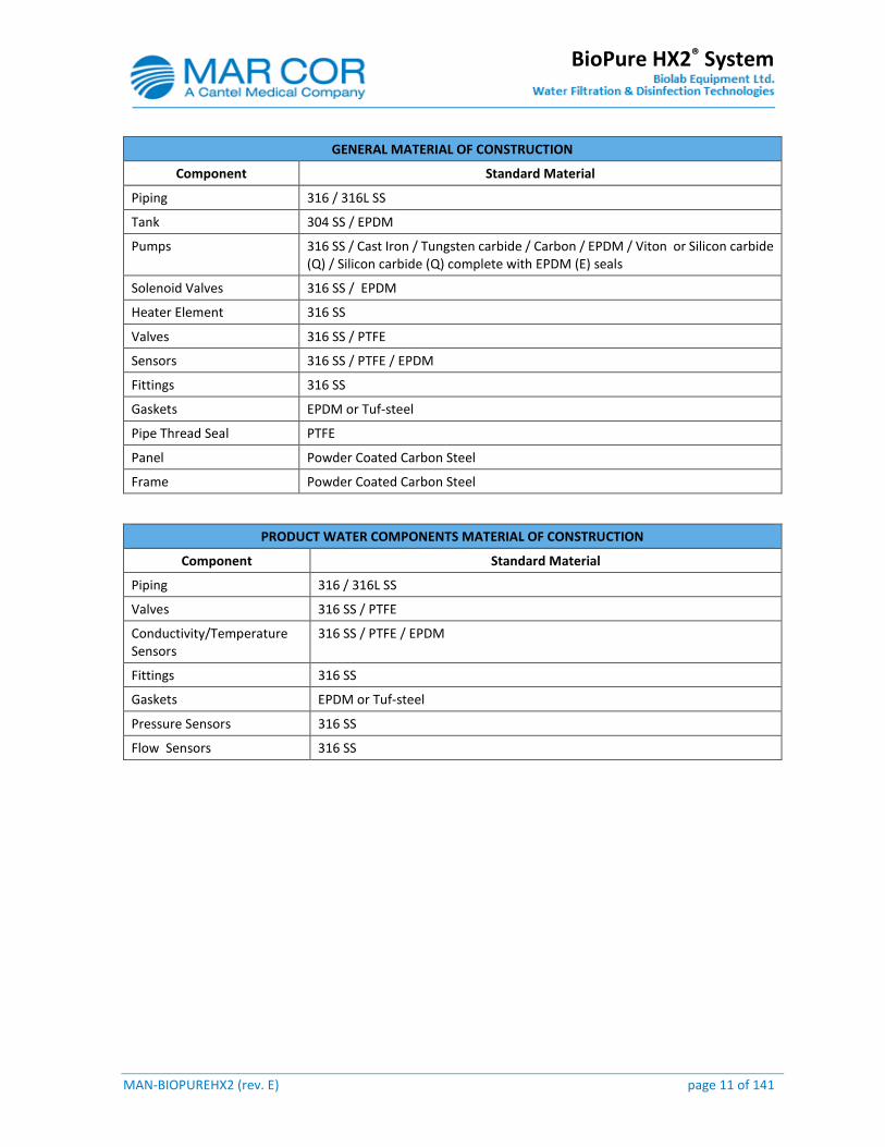
GENERAL MATERIAL OF CONSTRUCTION
Component Standard Material
Piping 316 / 316L SS
Tank 304 SS / EPDM
Pumps 316 SS / Cast Iron / Tungsten carbide / Carbon / EPDM / Viton or Silicon carbide (Q) / Silicon carbide (Q) complete with EPDM (E) seals
Solenoid Valves 316 SS / EPDM
Heater Element 316 SS
Valves 316 SS / PTFE
Sensors 316 SS / PTFE / EPDM
Fittings 316 SS
Gaskets EPDM or Tuf-steel
Pipe Thread Seal PTFE
Panel Powder Coated Carbon Steel
Frame Powder Coated Carbon Steel
PRODUCT WATER COMPONENTS MATERIAL OF CONSTRUCTION
Component Standard Material
Piping 316 / 316L SS
Valves 316 SS / PTFE
Conductivity/Temperature Sensors
316 SS / PTFE / EPDM
Fittings 316 SS
Gaskets EPDM or Tuf-steel
Pressure Sensors 316 SS
Flow Sensors 316 SS
MAN-BIOPUREHX2 (rev. E) page 12 of 141
BioPure HX2® System
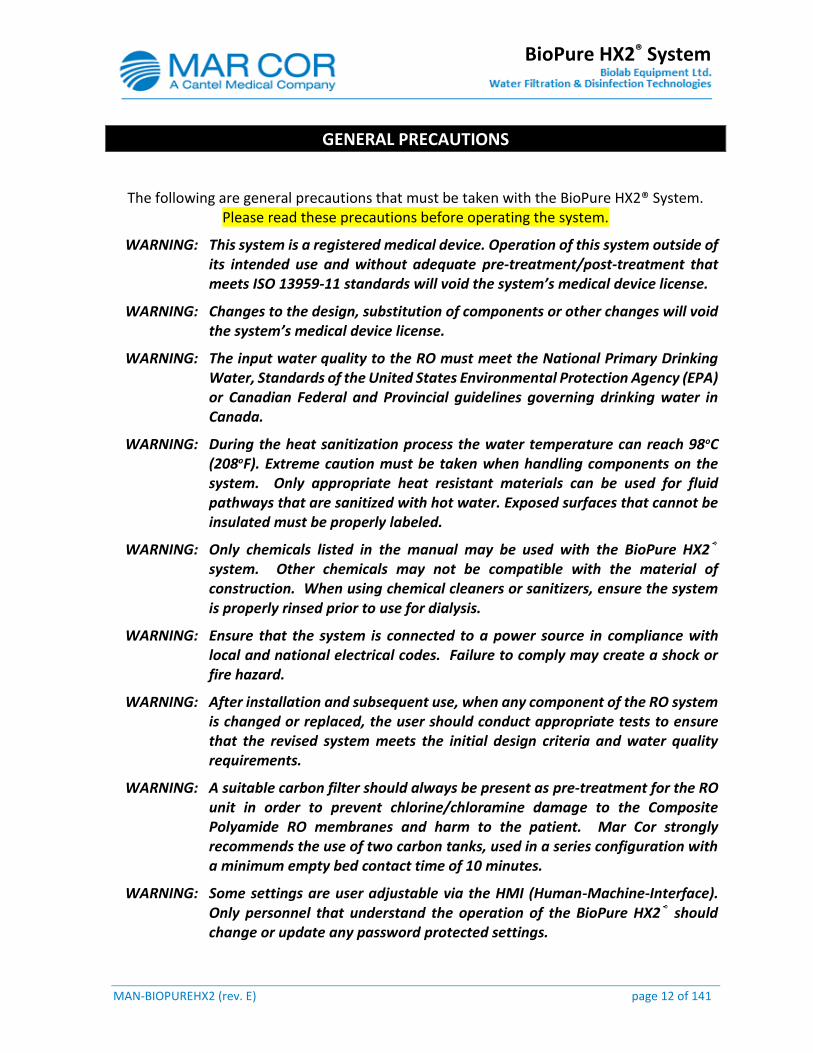
GENERAL PRECAUTIONS
The following are general precautions that must be taken with the BioPure HX2® System. Please read these precautions before operating the system.
WARNING: This system is a registered medical device. Operation of this system outside of its intended use and without adequate pre-treatment/post-treatment that meets ISO 13959-11 standards will void the system’s medical device license.
WARNING: Changes to the design, substitution of components or other changes will void the system’s medical device license.
WARNING: The input water quality to the RO must meet the National Primary Drinking Water, Standards of the United States Environmental Protection Agency (EPA) or Canadian Federal and Provincial guidelines governing drinking water in Canada.
WARNING: During the heat sanitization process the water temperature can reach 98oC (208oF). Extreme caution must be taken when handling components on the system. Only appropriate heat resistant materials can be used for fluid pathways that are sanitized with hot water. Exposed surfaces that cannot be insulated must be properly labeled.
WARNING: Only chemicals listed in the manual may be used with the BioPure HX2® system. Other chemicals may not be compatible with the material of construction. When using chemical cleaners or sanitizers, ensure the system is properly rinsed prior to use for dialysis.
WARNING: Ensure that the system is connected to a power source in compliance with local and national electrical codes. Failure to comply may create a shock or fire hazard.
WARNING: After installation and subsequent use, when any component of the RO system is changed or replaced, the user should conduct appropriate tests to ensure that the revised system meets the initial design criteria and water quality requirements.
WARNING: A suitable carbon filter should always be present as pre-treatment for the RO unit in order to prevent chlorine/chloramine damage to the Composite Polyamide RO membranes and harm to the patient. Mar Cor strongly recommends the use of two carbon tanks, used in a series configuration with a minimum empty bed contact time of 10 minutes.
WARNING: Some settings are user adjustable via the HMI (Human-Machine-Interface). Only personnel that understand the operation of the BioPure HX2® should change or update any password protected settings.
MAN-BIOPUREHX2 (rev. E) page 13 of 141
BioPure HX2® System
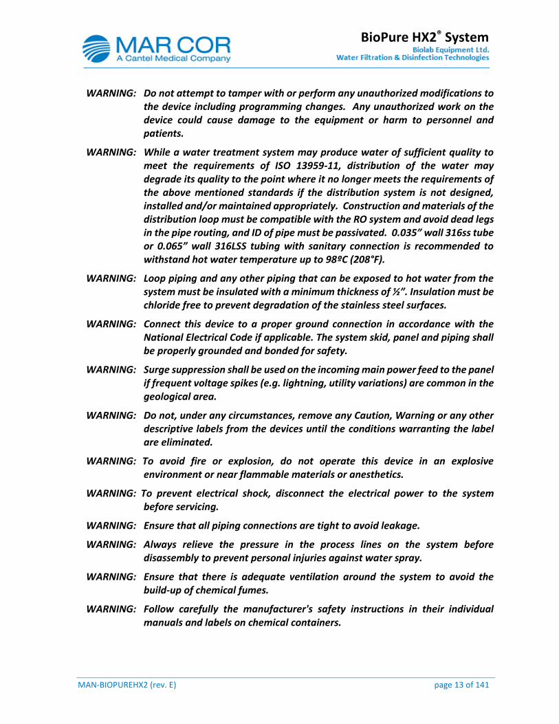
WARNING: Do not attempt to tamper with or perform any unauthorized modifications to the device including programming changes. Any unauthorized work on the device could cause damage to the equipment or harm to personnel and patients.
WARNING: While a water treatment system may produce water of sufficient quality to meet the requirements of ISO 13959-11, distribution of the water may degrade its quality to the point where it no longer meets the requirements of the above mentioned standards if the distribution system is not designed, installed and/or maintained appropriately. Construction and materials of the distribution loop must be compatible with the RO system and avoid dead legs in the pipe routing, and ID of pipe must be passivated. 0.035” wall 316ss tube or 0.065” wall 316LSS tubing with sanitary connection is recommended to withstand hot water temperature up to 98ºC (208°F).
WARNING: Loop piping and any other piping that can be exposed to hot water from the system must be insulated with a minimum thickness of ½”. Insulation must be chloride free to prevent degradation of the stainless steel surfaces.
WARNING: Connect this device to a proper ground connection in accordance with the National Electrical Code if applicable. The system skid, panel and piping shall be properly grounded and bonded for safety.
WARNING: Surge suppression shall be used on the incoming main power feed to the panel if frequent voltage spikes (e.g. lightning, utility variations) are common in the geological area.
WARNING: Do not, under any circumstances, remove any Caution, Warning or any other descriptive labels from the devices until the conditions warranting the label are eliminated.
WARNING: To avoid fire or explosion, do not operate this device in an explosive environment or near flammable materials or anesthetics.
WARNING: To prevent electrical shock, disconnect the electrical power to the system before servicing.
WARNING: Ensure that all piping connections are tight to avoid leakage.
WARNING: Always relieve the pressure in the process lines on the system before disassembly to prevent personal injuries against water spray.
WARNING: Ensure that there is adequate ventilation around the system to avoid the build-up of chemical fumes.
WARNING: Follow carefully the manufacturer's safety instructions in their individual manuals and labels on chemical containers.

MAN-BIOPUREHX2 (rev. E) page 14 of 141
BioPure HX2® System
CAUTION: To avoid physical and/or equipment harm, be cautious to use appropriate tools to move any components on the RO system (i.e. Use a mobile hoist to remove pump motor).
NOTE: The term ‘RO system’, “water system or “water purification system” used throughout this manual equally identify BioPure HX2® System.
NOTE: Use proper wiring and connection methods to satisfy hospital electrical codes if applicable.
NOTE: Use proper water and drain connections to prevent contamination of the RO and danger to the patient.
NOTE: The percent rejection is calculated based on feed water after mixing with some recycled reject water.
NOTE: Use a clean soft cloth with a mild soap or detergent to clean the HMI display. Dry the display with a chamois or moist cellulose sponge to avoid water spots. Remove fresh paint splashes and grease before drying by rubbing lightly with isopropyl alcohol (70% concentration). Afterward, wash using a mild soap or detergent. Rinse with clean water.
MAN-BIOPUREHX2 (rev. E) page 15 of 141
BioPure HX2® System
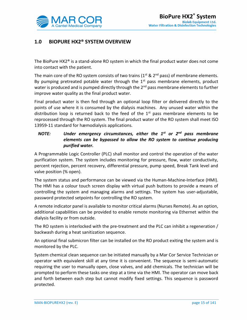
1.0 BIOPURE HX2® SYSTEM OVERVIEW
The BioPure HX2® is a stand-alone RO system in which the final product water does not come into contact with the patient.
The main core of the RO system consists of two trains (1st & 2nd pass) of membrane elements. By pumping pretreated potable water through the 1st pass membrane elements, product water is produced and is pumped directly through the 2nd pass membrane elements to further improve water quality as the final product water.
Final product water is then fed through an optional loop filter or delivered directly to the points of use where it is consumed by the dialysis machines. Any unused water within the distribution loop is returned back to the feed of the 1st pass membrane elements to be reprocessed through the RO system. The final product water of the RO system shall meet ISO 13959-11 standard for hæmodialysis applications.
NOTE: Under emergency circumstances, either the 1st or 2nd pass membrane elements can be bypassed to allow the RO system to continue producing purified water.
A Programmable Logic Controller (PLC) shall monitor and control the operation of the water purification system. The system includes monitoring for pressure, flow, water conductivity, percent rejection, percent recovery, differential pressure, pump speed, Break Tank level and valve position (% open).
The system status and performance can be viewed via the Human-Machine-Interface (HMI). The HMI has a colour touch screen display with virtual push buttons to provide a means of controlling the system and managing alarms and settings. The system has user-adjustable, password protected setpoints for controlling the RO system.
A remote indicator panel is available to monitor critical alarms (Nurses Remote). As an option, additional capabilities can be provided to enable remote monitoring via Ethernet within the dialysis facility or from outside.
The RO system is interlocked with the pre-treatment and the PLC can inhibit a regeneration / backwash during a heat sanitization sequence.
An optional final submicron filter can be installed on the RO product exiting the system and is monitored by the PLC.
System chemical clean sequence can be initiated manually by a Mar Cor Service Technician or operator with equivalent skill at any time it is convenient. The sequence is semi-automatic requiring the user to manually open, close valves, and add chemicals. The technician will be prompted to perform these tasks one step at a time via the HMI. The operator can move back and forth between each step but cannot modify fixed settings. This sequence is password protected.
MAN-BIOPUREHX2 (rev. E) page 16 of 141
BioPure HX2® System
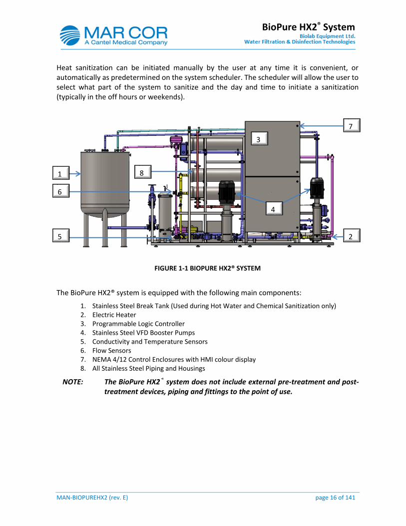
Heat sanitization can be initiated manually by the user at any time it is convenient, or automatically as predetermined on the system scheduler. The scheduler will allow the user to select what part of the system to sanitize and the day and time to initiate a sanitization (typically in the off hours or weekends).
FIGURE 1-1 BIOPURE HX2® SYSTEM
The BioPure HX2® system is equipped with the following main components:
1. Stainless Steel Break Tank (Used during Hot Water and Chemical Sanitization only) 2. Electric Heater 3. Programmable Logic Controller 4. Stainless Steel VFD Booster Pumps 5. Conductivity and Temperature Sensors 6. Flow Sensors 7. NEMA 4/12 Control Enclosures with HMI colour display 8. All Stainless Steel Piping and Housings
NOTE: The BioPure HX2® system does not include external pre-treatment and post-treatment devices, piping and fittings to the point of use.
1
6
5 2
8
3
4
7
MAN-BIOPUREHX2 (rev. E) page 17 of 141
BioPure HX2® System
2.0 INSTALLATION REQUIREMENTS
Refer to the BioPure HX2® “System Installation Manual” for instructions of the following:
UNPACKING THE SYSTEM
SPACE ∕ ROOM REQUIREMENTS
LOADING AND UNLOADING SYSTEM SKID
PIPING REQUIREMENTS
PIPING INSULATION
ELECTRICAL HOOK-UP
PRE-TREATED FEED WATER REQUIREMENTS
MAN-BIOPUREHX2 (rev. E) page 18 of 141
BioPure HX2® System
3.0 SYSTEM CONTROL OVERVIEW
The system is controlled by a Programmable Logic Controller (PLC) that sends and receives signals to and from various devices and sensors on the system. The status of selected devices and sensors, as well as the overall system performance can be viewed at various screens of the Human-Machine-Interface (HMI) display located on front of the control panel. Screens containing setpoint values are adjustable with password protection.
NOTE: There is a red emergency stop push button (E-Stop) on the front of the control panel that allows the users to terminate the system operation upon an emergency situation. Once E-Stop is activated, the system will transition to ‘Off’ mode and all output devices will stop.
NOTE: The remote monitoring HMI at the nursing station is strictly designed for monitoring purposes only. It has absolutely no access to make setpoints adjustment to alter the system performance.
SECURITY
Various screens can be viewed and accessed from the HMI display. Each screen serves a specific function to allow users to monitor system status, performance and/or adjust the system setpoints. Some of the screens and setpoints have security restrictions and require a password.
NOTE: Once the user has logged in and there is no HMI activity detected a 10 minute timer will count down and automatically log out the user. The user can also log out by pressing the icon if desired.
There are three levels of security and they can be accessed by pressing the login icon on the HMI and must enter the login user name followed by the password. Access levels are as follows:
Login Name: Operator and Default Password: 1 (Level 1)
Mode selection (“OFF”, “STANDBY”, “AUTOMATIC”)
Acknowledge alarms
Reset alarms
No access to setpoints
Login Name: Supervisor and Default Password: 2 (Level 2)
All of the above
Modify scheduler
Adjust setpoints with User Access Level = 2 or less.
Access MAINTENANCE Mode

MAN-BIOPUREHX2 (rev. E) page 19 of 141
BioPure HX2® System
Login Name: Administration and Default Password: 3 (Level 3)
All of the above
Adjust setpoints with User Access Level = 3 or less.
Security, change passwords
Time and date
ALARM MANAGEMENT
When an alarm has occurred the user may press the alarm silence button on the HMI panel to silence the alarm.
The user shall determine the corrective action by looking at the alarm banner on the HMI and correct the alarm condition(s). Once corrected, the alarm banner can be cleared and the reset button pressed on the HMI to restart the system.
When the alarm silence is pressed and no action is taken the horn will reactivate after 120 seconds. This cycle will repeat every time the alarm silence button is pressed and no action is taken.
The user will be able to view alarms, both current and historical. The user will be able to do the following;
Silence the alarm horn by pressing the “SILENCE ALARMS” button.
Reset all alarms/alerts allowing the system to be restarted by pressing the “ALARM RESET” button.
Acknowledge and date-stamp the current active alarm by pressing the “ACK” button.
Acknowledge and date-stamp all active alarms by pressing the “ACK ALL” button
3.2.1 Main Control Panel Status and Alarm Indicator Function
The system status is displayed on the local HMI screen.
The description and function is as follows:
Automatic Green Indicator (AU): The green indicator shall turn on when the system is in AUTOMATIC.
Maintenance Amber Indicator (M): The amber indicator shall turn on when the system is in MAINTENANCE. The indicator shall turn on for the following.
Pre-treatment Lockout (only if single filter pre-treatment devices are used – non-redundant systems)
RO Flush
Loop Flush
Heat Sanitization
Chemical Clean
MAN-BIOPUREHX2 (rev. E) page 20 of 141
BioPure HX2® System
When any device (control module) is not in auto mode on the HMI.
Alarm Red Indicator (AL): The indicator shall turn on when an alarm has occurred. An alarm banner will appear on the HMI, and will be logged in the alarm history.
Loss of communication between any of the HMI devices (Main or Remote Nurse’s Station or Remote Monitoring system) and the PLC will initial a local alert on the device with lost communication. Alert only.
NOTE: An optional 24VDC remote stack light can be installed if system status and alarm indicator is required.
REMOTE NURSE`S STATION MONITOR AND ALARM INDICATOR
The system status is displayed on a remotely mounted HMI display (Nurses Station). It shall be limited on view only information except for silencing the audible alarm. The description and function are as follows:
The remote HMI mimics the main screen on the central system. It will display the system status, operational information, alerts and alarms in real time. If a critical alarm occurs the remote audible alarm will activate. The user can silence the audible alarm from the remote HMI or from the main control panel. The user can only reset the alarm from the central system HMI. The remote nurse’s station monitor shall indicate loss of communication with the PLC as an alert. Alert only.
During a heat sanitization or chemical cleaning / sanitization the audible alarm will sound intermittently (every 15 seconds for approx. ½ a second).
The remote audible alarm, if silenced, will re-alarm in less than 120 seconds.
The maximum length for the Ethernet cable segment used to connect the nurse’s station to the control panel must not be longer than 300’. If the cable distance is greater than 300’ the use of active hardware such as a repeater, switch or router shall be necessary to boost the signal.
USB DRIVE AND PRINTER (optional)
The system is equipped with two (2) USB ports on the left side of the panel. Description and use of each port is as follows:
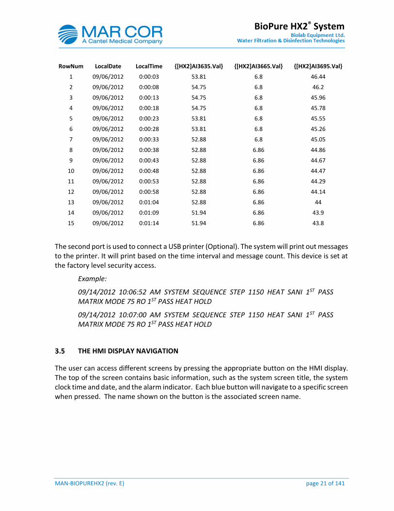
The first port is used to connect a USB drive (optional) to collect real time raw data from the HMI in a csv format that can be viewed using Microsoft Excel. When viewed the columns have tags and or descriptions that indicate what the values correspond to. The tags can be referenced on the process flow drawing. The data can be filtered using Excel to create system performance reports. This device is set at the factory level security access.
MAN-BIOPUREHX2 (rev. E) page 21 of 141
BioPure HX2® System
RowNum LocalDate LocalTime {[HX2]AI3635.Val} {[HX2]AI3665.Val} {[HX2]AI3695.Val}
1 09/06/2012 0:00:03 53.81 6.8 46.44
2 09/06/2012 0:00:08 54.75 6.8 46.2
3 09/06/2012 0:00:13 54.75 6.8 45.96
4 09/06/2012 0:00:18 54.75 6.8 45.78
5 09/06/2012 0:00:23 53.81 6.8 45.55
6 09/06/2012 0:00:28 53.81 6.8 45.26
7 09/06/2012 0:00:33 52.88 6.8 45.05
8 09/06/2012 0:00:38 52.88 6.86 44.86
9 09/06/2012 0:00:43 52.88 6.86 44.67
10 09/06/2012 0:00:48 52.88 6.86 44.47
11 09/06/2012 0:00:53 52.88 6.86 44.29
12 09/06/2012 0:00:58 52.88 6.86 44.14
13 09/06/2012 0:01:04 52.88 6.86 44
14 09/06/2012 0:01:09 51.94 6.86 43.9
15 09/06/2012 0:01:14 51.94 6.86 43.8
The second port is used to connect a USB printer (Optional). The system will print out messages to the printer. It will print based on the time interval and message count. This device is set at the factory level security access.
Example:
09/14/2012 10:06:52 AM SYSTEM SEQUENCE STEP 1150 HEAT SANI 1ST PASS MATRIX MODE 75 RO 1ST PASS HEAT HOLD
09/14/2012 10:07:00 AM SYSTEM SEQUENCE STEP 1150 HEAT SANI 1ST PASS MATRIX MODE 75 RO 1ST PASS HEAT HOLD
THE HMI DISPLAY NAVIGATION
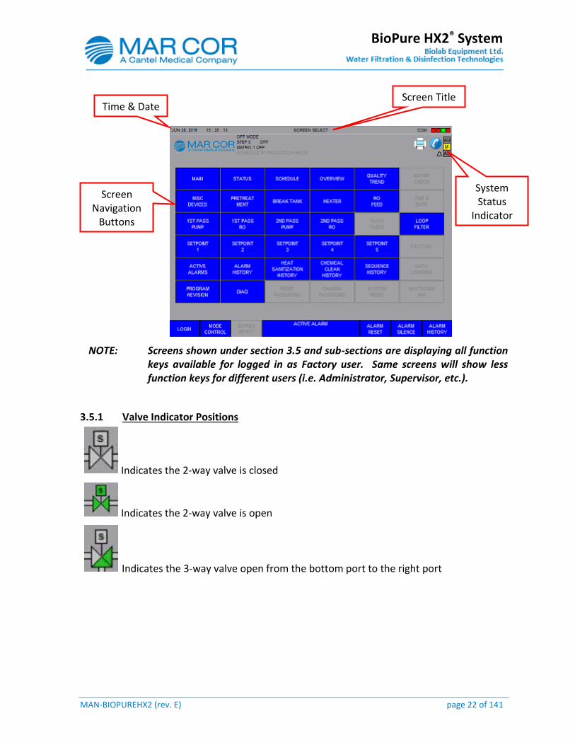
The user can access different screens by pressing the appropriate button on the HMI display. The top of the screen contains basic information, such as the system screen title, the system clock time and date, and the alarm indicator. Each blue button will navigate to a specific screen when pressed. The name shown on the button is the associated screen name.
MAN-BIOPUREHX2 (rev. E) page 22 of 141
BioPure HX2® System
NOTE: Screens shown under section 3.5 and sub-sections are displaying all function keys available for logged in as Factory user. Same screens will show less function keys for different users (i.e. Administrator, Supervisor, etc.).
3.5.1 Valve Indicator Positions
Indicates the 2-way valve is closed
Indicates the 2-way valve is open
Indicates the 3-way valve open from the bottom port to the right port
Time & Date Screen Title
System Status
Indicator
Screen Navigation
Buttons
MAN-BIOPUREHX2 (rev. E) page 23 of 141
BioPure HX2® System
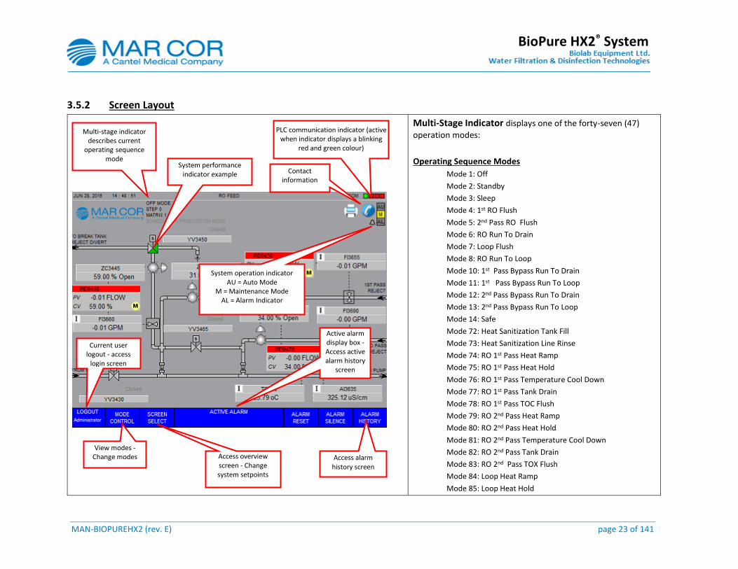
3.5.2 Screen Layout
Multi-Stage Indicator displays one of the forty-seven (47)
operation modes:
Operating Sequence Modes
Mode 1: Off
Mode 2: Standby
Mode 3: Sleep
Mode 4: 1st RO Flush
Mode 5: 2nd Pass RO Flush
Mode 6: RO Run To Drain
Mode 7: Loop Flush
Mode 8: RO Run To Loop
Mode 10: 1st Pass Bypass Run To Drain
Mode 11: 1st Pass Bypass Run To Loop
Mode 12: 2nd Pass Bypass Run To Drain
Mode 13: 2nd Pass Bypass Run To Loop
Mode 14: Safe
Mode 72: Heat Sanitization Tank Fill
Mode 73: Heat Sanitization Line Rinse
Mode 74: RO 1st Pass Heat Ramp
Mode 75: RO 1st Pass Heat Hold
Mode 76: RO 1st Pass Temperature Cool Down
Mode 77: RO 1st Pass Tank Drain
Mode 78: RO 1st Pass TOC Flush
Mode 79: RO 2nd Pass Heat Ramp
Mode 80: RO 2nd Pass Heat Hold
Mode 81: RO 2nd Pass Temperature Cool Down
Mode 82: RO 2nd Pass Tank Drain
Mode 83: RO 2nd Pass TOX Flush
Mode 84: Loop Heat Ramp
Mode 85: Loop Heat Hold
Multi-stage indicator describes current
operating sequence mode
System performance
indicator example
Access overview screen - Change system setpoints
PLC communication indicator (active when indicator displays a blinking
red and green colour)
System operation indicator AU = Auto Mode
M = Maintenance Mode AL = Alarm Indicator
Active alarm display box - Access active alarm history
screen
Access alarm history screen
Current user logout - access
login screen
View modes -Change modes
Contact information
MAN-BIOPUREHX2 (rev. E) page 24 of 141
BioPure HX2® System
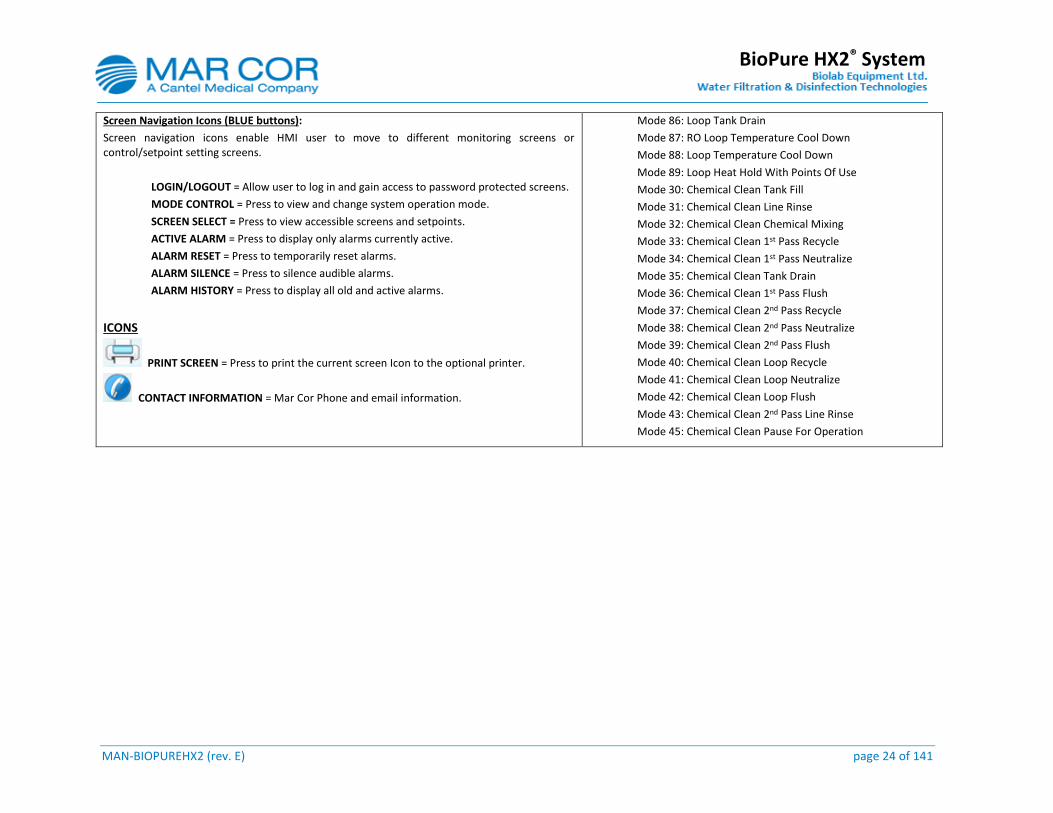
Screen Navigation Icons (BLUE buttons):
Screen navigation icons enable HMI user to move to different monitoring screens or control/setpoint setting screens.
LOGIN/LOGOUT = Allow user to log in and gain access to password protected screens.
MODE CONTROL = Press to view and change system operation mode.
SCREEN SELECT = Press to view accessible screens and setpoints.
ACTIVE ALARM = Press to display only alarms currently active.
ALARM RESET = Press to temporarily reset alarms.
ALARM SILENCE = Press to silence audible alarms.
ALARM HISTORY = Press to display all old and active alarms.
ICONS
PRINT SCREEN = Press to print the current screen Icon to the optional printer.
CONTACT INFORMATION = Mar Cor Phone and email information.
Mode 86: Loop Tank Drain
Mode 87: RO Loop Temperature Cool Down
Mode 88: Loop Temperature Cool Down
Mode 89: Loop Heat Hold With Points Of Use
Mode 30: Chemical Clean Tank Fill
Mode 31: Chemical Clean Line Rinse
Mode 32: Chemical Clean Chemical Mixing
Mode 33: Chemical Clean 1st Pass Recycle
Mode 34: Chemical Clean 1st Pass Neutralize
Mode 35: Chemical Clean Tank Drain
Mode 36: Chemical Clean 1st Pass Flush
Mode 37: Chemical Clean 2nd Pass Recycle
Mode 38: Chemical Clean 2nd Pass Neutralize
Mode 39: Chemical Clean 2nd Pass Flush
Mode 40: Chemical Clean Loop Recycle
Mode 41: Chemical Clean Loop Neutralize
Mode 42: Chemical Clean Loop Flush
Mode 43: Chemical Clean 2nd Pass Line Rinse
Mode 45: Chemical Clean Pause For Operation

MAN-BIOPUREHX2 (rev. E) page 25 of 141
BioPure HX2® System
3.5.3 Screen Selection
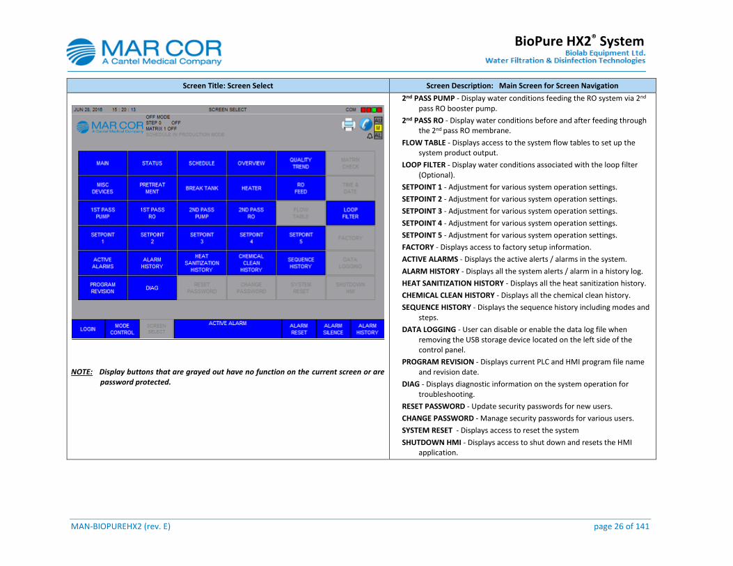
Screen Title: Screen Select Screen Description: Main Screen for Screen Navigation
The purpose of this screen is to allow the USER to navigate to different HMI screens.
Factory Access
User Screen (No Password)
Multi-Stage Indicator displays one of the forty-six (46) operation modes. See section 3.5.2 to review the list of modes and description on the HMI.
MONITORING SCREENS
MAIN - Displays system performance on 1st Pass RO water quality, 2nd Pass RO water quality and temperature, Loop Feed flow rate, and Loop Return flow rate.
STATUS - Control interface for current operation status and maintenance functions.
SCHEDULE - Displays the pre-set time scheduler for system operation in Normal Production and Heat Sanitization.
OVERVIEW - Displays real-time system performance.
QUALITY TREND - Displays Conductivity measurements versus Time on the system.
MATRIX CHECK - Displays the position indicator on the valve and determines its physical position.
MISC. DEVICES - Displays operation status of miscellaneous components: Remote Audible Alarm, Audible Alarm, System Alarm Relay, Water Leak, DI Alarm, DI Active, Auxiliary Input, Main Power, Main E-Stop, Alarm Silence, and Compressed Air.
PRE-TREATMENT - Displays operation status of automatic pre-treatment systems: Softeners, Media Filters, and Carbon Filters.
BREAK TANK - Displays component operation and system performance associated with the break tank. Break tank is strictly used for heat sanitization.
HEATER - Displays component operation and system performance associated with the heater. Heater is strictly used for heat sanitization.
RO FEED - Display water conditions feeding the RO system.
TIME & DATE - Adjustment for HMI time and date.
1ST PASS PUMP - Display water conditions feeding the RO system via 1st pass RO booster pump.
1ST PASS RO - Display water conditions before and after feeding through the 1st pass RO membrane.
Press icon to move to corresponding screen
Multi-Stage Indicator
MAN-BIOPUREHX2 (rev. E) page 26 of 141
BioPure HX2® System
Screen Title: Screen Select Screen Description: Main Screen for Screen Navigation
NOTE: Display buttons that are grayed out have no function on the current screen or are password protected.
2nd PASS PUMP - Display water conditions feeding the RO system via 2nd pass RO booster pump.
2nd PASS RO - Display water conditions before and after feeding through the 2nd pass RO membrane.
FLOW TABLE - Displays access to the system flow tables to set up the system product output.
LOOP FILTER - Display water conditions associated with the loop filter (Optional).
SETPOINT 1 - Adjustment for various system operation settings.
SETPOINT 2 - Adjustment for various system operation settings.
SETPOINT 3 - Adjustment for various system operation settings.
SETPOINT 4 - Adjustment for various system operation settings.
SETPOINT 5 - Adjustment for various system operation settings.
FACTORY - Displays access to factory setup information.
ACTIVE ALARMS - Displays the active alerts / alarms in the system.
ALARM HISTORY - Displays all the system alerts / alarm in a history log.
HEAT SANITIZATION HISTORY - Displays all the heat sanitization history.
CHEMICAL CLEAN HISTORY - Displays all the chemical clean history.
SEQUENCE HISTORY - Displays the sequence history including modes and steps.
DATA LOGGING - User can disable or enable the data log file when removing the USB storage device located on the left side of the control panel.
PROGRAM REVISION - Displays current PLC and HMI program file name and revision date.
DIAG - Displays diagnostic information on the system operation for troubleshooting.
RESET PASSWORD - Update security passwords for new users.
CHANGE PASSWORD - Manage security passwords for various users.
SYSTEM RESET - Displays access to reset the system
SHUTDOWN HMI - Displays access to shut down and resets the HMI application.
MAN-BIOPUREHX2 (rev. E) page 27 of 141
BioPure HX2® System
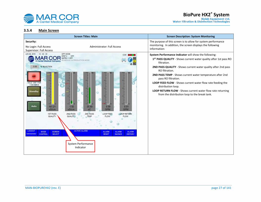
3.5.4 Main Screen
Screen Titles: Main Screen Description: System Monitoring
Security: The purpose of this screen is to allow for system performance monitoring. In addition, the screen displays the following information:
No Login: Full Access Supervisor: Full Access
Administrator: Full Access
System Performance Indicator will show the following:
1ST PASS QUALITY - Shows current water quality after 1st pass RO filtration.
2ND PASS QUALITY - Shows current water quality after 2nd pass RO filtration.
2ND PASS TEMP - Shows current water temperature after 2nd pass RO filtration.
LOOP FEED FLOW - Shows current water flow rate feeding the distribution loop.
LOOP RETURN FLOW - Shows current water flow rate returning from the distribution loop to the break tank.
System Performance Indicator
MAN-BIOPUREHX2 (rev. E) page 28 of 141
BioPure HX2® System
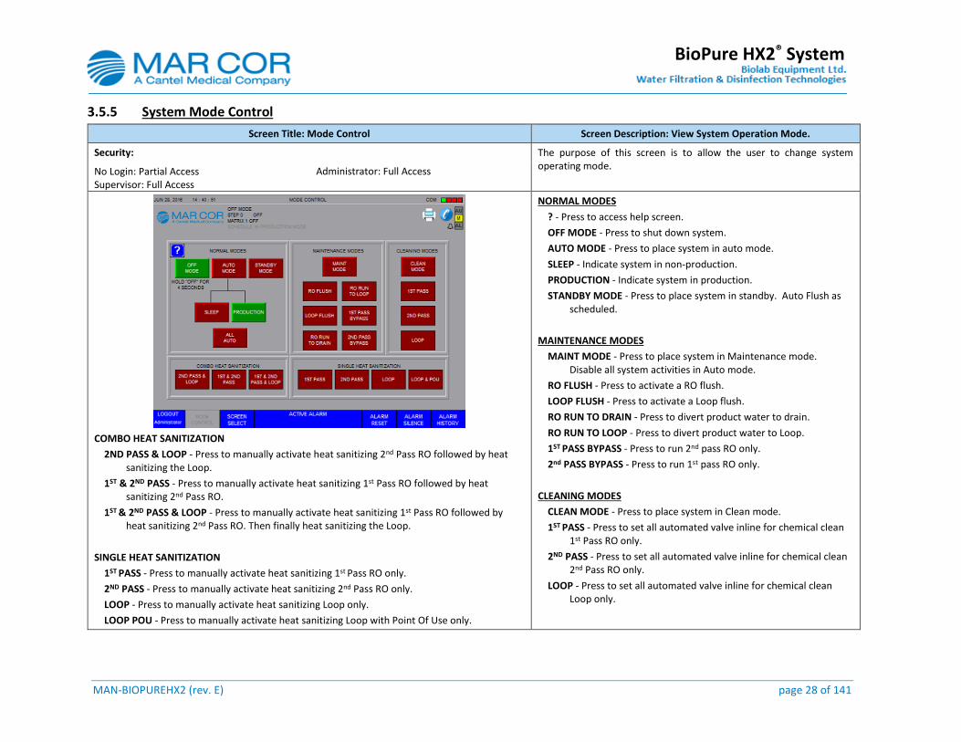
3.5.5 System Mode Control
Screen Title: Mode Control Screen Description: View System Operation Mode.
Security: The purpose of this screen is to allow the user to change system operating mode.
No Login: Partial Access Supervisor: Full Access
Administrator: Full Access
COMBO HEAT SANITIZATION
2ND PASS & LOOP - Press to manually activate heat sanitizing 2nd Pass RO followed by heat sanitizing the Loop.
1ST & 2ND PASS - Press to manually activate heat sanitizing 1st Pass RO followed by heat sanitizing 2nd Pass RO.
1ST & 2ND PASS & LOOP - Press to manually activate heat sanitizing 1st Pass RO followed by heat sanitizing 2nd Pass RO. Then finally heat sanitizing the Loop.
SINGLE HEAT SANITIZATION
1ST PASS - Press to manually activate heat sanitizing 1st Pass RO only.
2ND PASS - Press to manually activate heat sanitizing 2nd Pass RO only.
LOOP - Press to manually activate heat sanitizing Loop only.
LOOP POU - Press to manually activate heat sanitizing Loop with Point Of Use only.
NORMAL MODES
? - Press to access help screen.
OFF MODE - Press to shut down system.
AUTO MODE - Press to place system in auto mode.
SLEEP - Indicate system in non-production.
PRODUCTION - Indicate system in production.
STANDBY MODE - Press to place system in standby. Auto Flush as scheduled.
MAINTENANCE MODES
MAINT MODE - Press to place system in Maintenance mode. Disable all system activities in Auto mode.
RO FLUSH - Press to activate a RO flush.
LOOP FLUSH - Press to activate a Loop flush.
RO RUN TO DRAIN - Press to divert product water to drain.
RO RUN TO LOOP - Press to divert product water to Loop.
1ST PASS BYPASS - Press to run 2nd pass RO only.
2nd PASS BYPASS - Press to run 1st pass RO only.
CLEANING MODES
CLEAN MODE - Press to place system in Clean mode.
1ST PASS - Press to set all automated valve inline for chemical clean 1st Pass RO only.
2ND PASS - Press to set all automated valve inline for chemical clean 2nd Pass RO only.
LOOP - Press to set all automated valve inline for chemical clean Loop only.
MAN-BIOPUREHX2 (rev. E) page 29 of 141
BioPure HX2® System
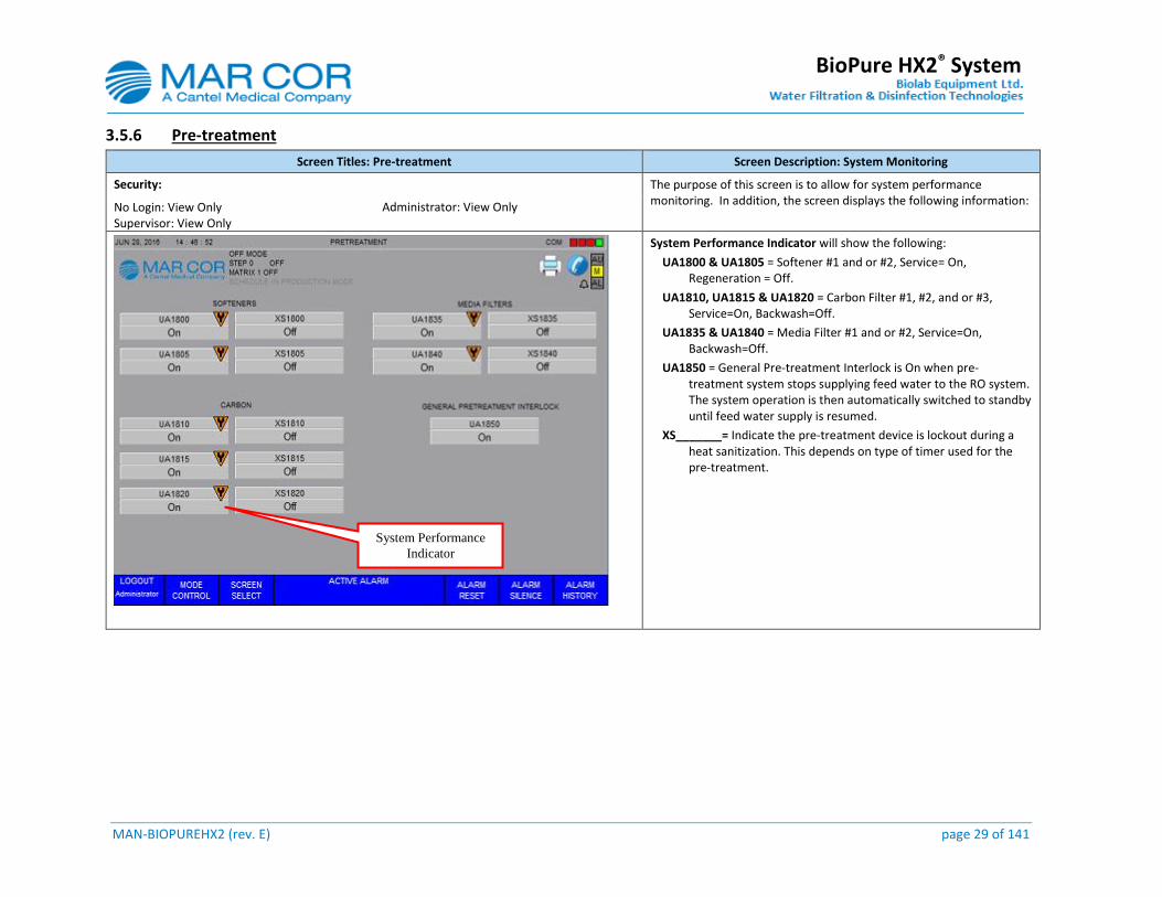
3.5.6 Pre-treatment
Screen Titles: Pre-treatment Screen Description: System Monitoring
Security: The purpose of this screen is to allow for system performance monitoring. In addition, the screen displays the following information:
No Login: View Only Supervisor: View Only
Administrator: View Only
System Performance Indicator will show the following:
UA1800 & UA1805 = Softener #1 and or #2, Service= On, Regeneration = Off.
UA1810, UA1815 & UA1820 = Carbon Filter #1, #2, and or #3, Service=On, Backwash=Off.
UA1835 & UA1840 = Media Filter #1 and or #2, Service=On, Backwash=Off.
UA1850 = General Pre-treatment Interlock is On when pre-treatment system stops supplying feed water to the RO system. The system operation is then automatically switched to standby until feed water supply is resumed.
XS_______= Indicate the pre-treatment device is lockout during a heat sanitization. This depends on type of timer used for the pre-treatment.
System Performance
Indicator
MAN-BIOPUREHX2 (rev. E) page 30 of 141
BioPure HX2® System
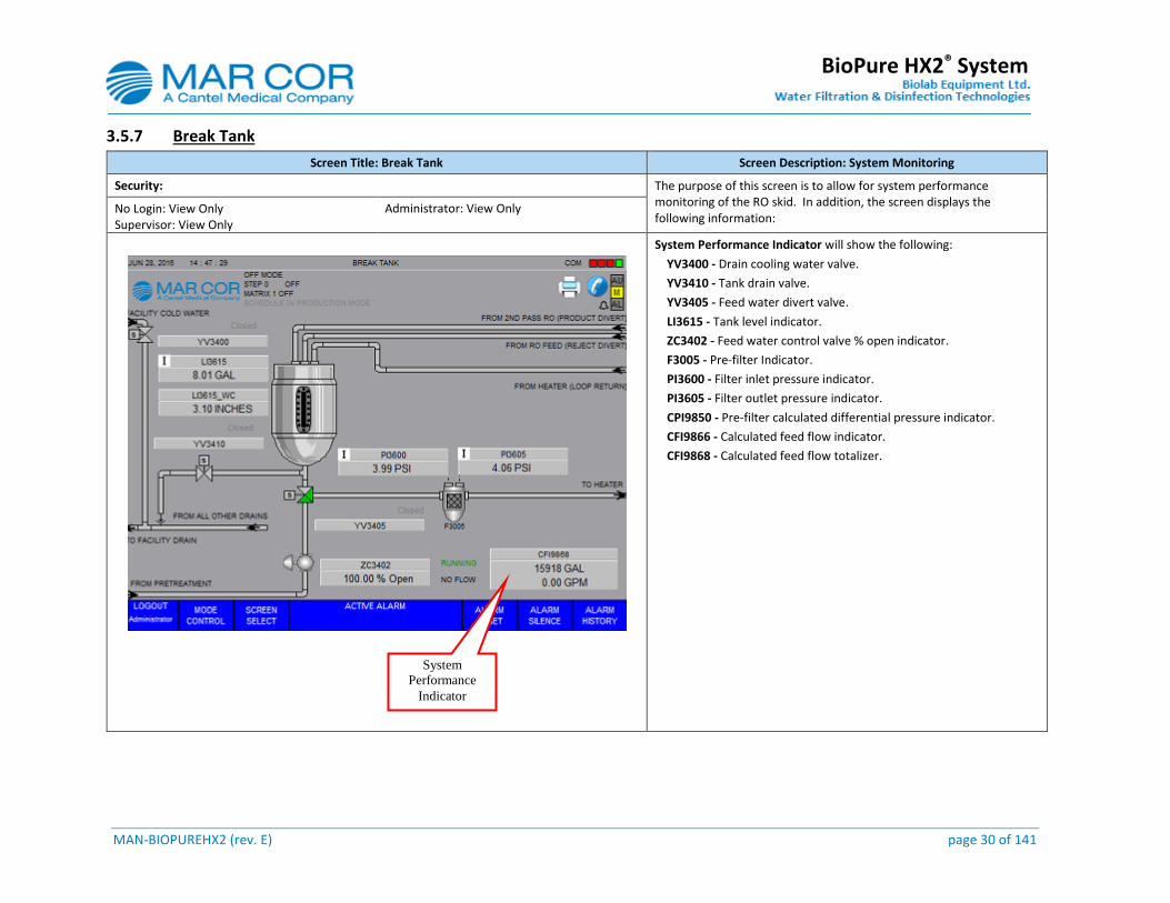
3.5.7 Break Tank
Screen Title: Break Tank Screen Description: System Monitoring
Security: The purpose of this screen is to allow for system performance monitoring of the RO skid. In addition, the screen displays the following information:
No Login: View Only Supervisor: View Only
Administrator: View Only
System Performance Indicator will show the following:
YV3400 - Drain cooling water valve.
YV3410 - Tank drain valve.
YV3405 - Feed water divert valve.
LI3615 - Tank level indicator.
ZC3402 - Feed water control valve % open indicator.
F3005 - Pre-filter Indicator.
PI3600 - Filter inlet pressure indicator.
PI3605 - Filter outlet pressure indicator.
CPI9850 - Pre-filter calculated differential pressure indicator.
CFI9866 - Calculated feed flow indicator.
CFI9868 - Calculated feed flow totalizer.
System
Performance
Indicator
MAN-BIOPUREHX2 (rev. E) page 31 of 141
BioPure HX2® System
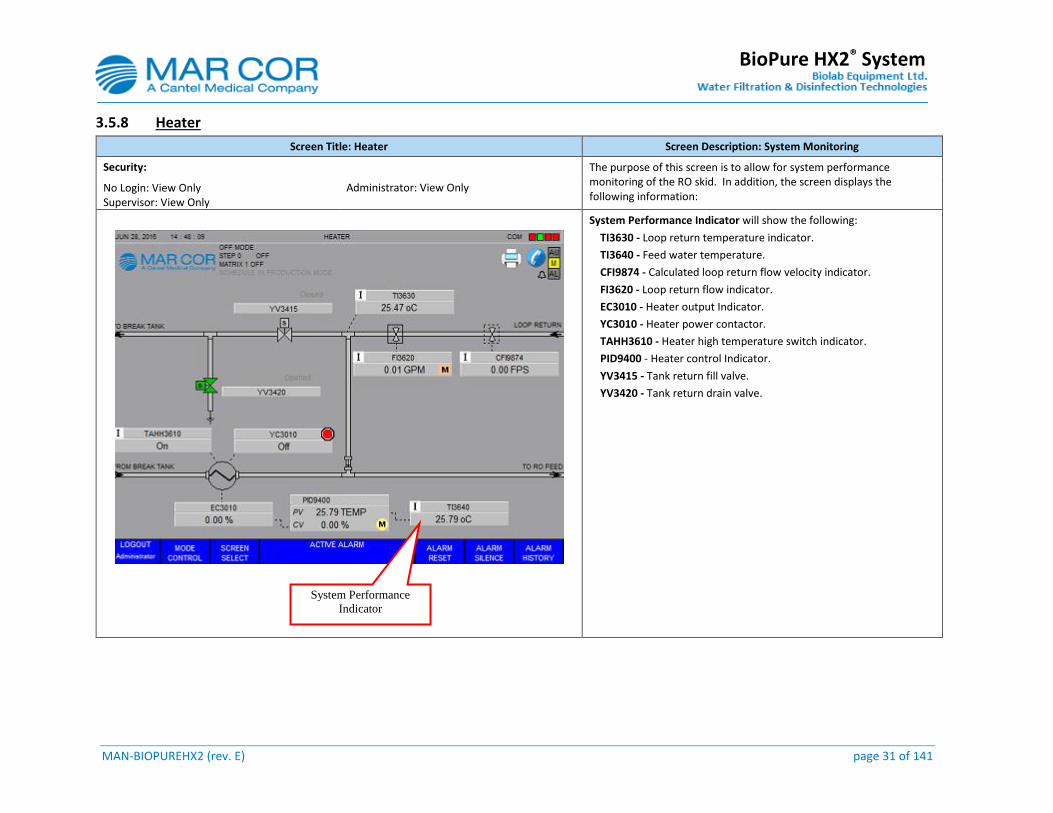
3.5.8 Heater
Screen Title: Heater Screen Description: System Monitoring
Security: The purpose of this screen is to allow for system performance monitoring of the RO skid. In addition, the screen displays the following information:
No Login: View Only Supervisor: View Only
Administrator: View Only
System Performance Indicator will show the following:
TI3630 - Loop return temperature indicator.
TI3640 - Feed water temperature.
CFI9874 - Calculated loop return flow velocity indicator.
FI3620 - Loop return flow indicator.
EC3010 - Heater output Indicator.
YC3010 - Heater power contactor.
TAHH3610 - Heater high temperature switch indicator.
PID9400 - Heater control Indicator.
YV3415 - Tank return fill valve.
YV3420 - Tank return drain valve.
System Performance
Indicator
MAN-BIOPUREHX2 (rev. E) page 32 of 141
BioPure HX2® System
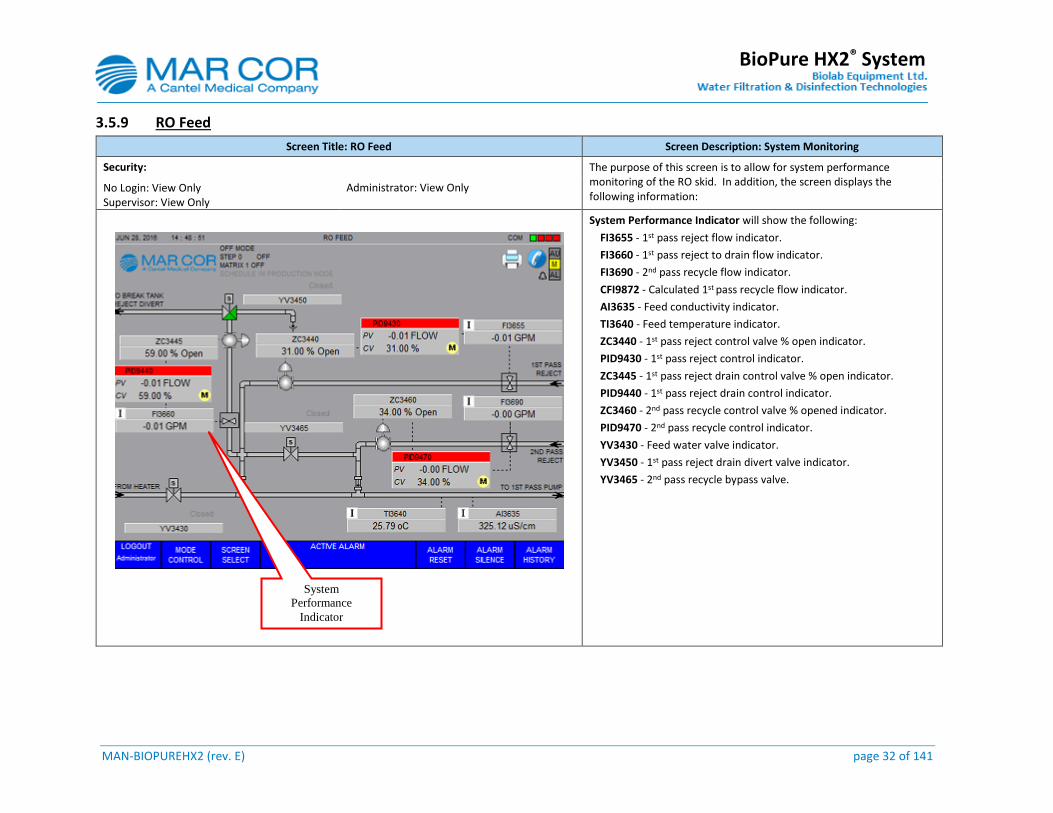
3.5.9 RO Feed
Screen Title: RO Feed Screen Description: System Monitoring
Security: The purpose of this screen is to allow for system performance monitoring of the RO skid. In addition, the screen displays the following information:
No Login: View Only Supervisor: View Only
Administrator: View Only
System Performance Indicator will show the following:
FI3655 - 1st pass reject flow indicator.
FI3660 - 1st pass reject to drain flow indicator.
FI3690 - 2nd pass recycle flow indicator.
CFI9872 - Calculated 1st pass recycle flow indicator.
AI3635 - Feed conductivity indicator.
TI3640 - Feed temperature indicator.
ZC3440 - 1st pass reject control valve % open indicator.
PID9430 - 1st pass reject control indicator.
ZC3445 - 1st pass reject drain control valve % open indicator.
PID9440 - 1st pass reject drain control indicator.
ZC3460 - 2nd pass recycle control valve % opened indicator.
PID9470 - 2nd pass recycle control indicator.
YV3430 - Feed water valve indicator.
YV3450 - 1st pass reject drain divert valve indicator.
YV3465 - 2nd pass recycle bypass valve.
System
Performance
Indicator
MAN-BIOPUREHX2 (rev. E) page 33 of 141
BioPure HX2® System
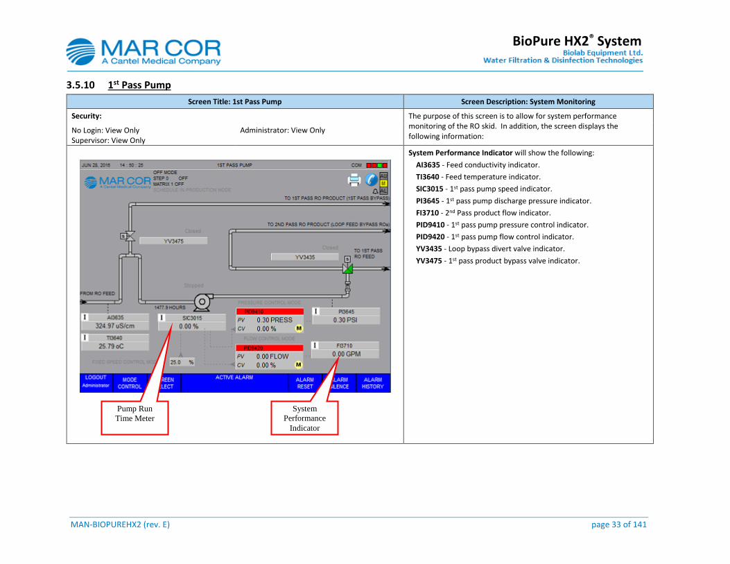
3.5.10 1st Pass Pump
Screen Title: 1st Pass Pump Screen Description: System Monitoring
Security: The purpose of this screen is to allow for system performance monitoring of the RO skid. In addition, the screen displays the following information:
No Login: View Only Supervisor: View Only
Administrator: View Only
System Performance Indicator will show the following:
AI3635 - Feed conductivity indicator.
TI3640 - Feed temperature indicator.
SIC3015 - 1st pass pump speed indicator.
PI3645 - 1st pass pump discharge pressure indicator.
FI3710 - 2nd Pass product flow indicator.
PID9410 - 1st pass pump pressure control indicator.
PID9420 - 1st pass pump flow control indicator.
YV3435 - Loop bypass divert valve indicator.
YV3475 - 1st pass product bypass valve indicator.
System
Performance
Indicator
Pump Run
Time Meter
MAN-BIOPUREHX2 (rev. E) page 34 of 141
BioPure HX2® System
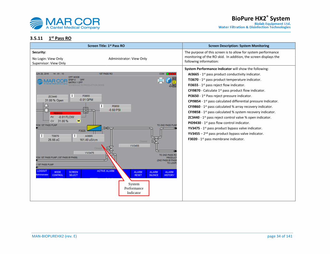
3.5.11 1st Pass RO
Screen Title: 1st Pass RO Screen Description: System Monitoring
Security: The purpose of this screen is to allow for system performance monitoring of the RO skid. In addition, the screen displays the following information:
No Login: View Only Supervisor: View Only
Administrator: View Only
System Performance Indicator will show the following:
AI3665 - 1st pass product conductivity indicator.
TI3670 - 1st pass product temperature indicator.
FI3655 - 1st pass reject flow indicator.
CFI9870 - Calculate 1st pass product flow indicator.
PI3650 - 1st Pass reject pressure indicator.
CPI9854 - 1st pass calculated differential pressure Indicator.
CFI9860 - 1st pass calculated % array recovery indicator.
CFI9858 - 1st pass calculated % system recovery indicator.
ZC3440 - 1st pass reject control valve % open indicator.
PID9430 - 1st pass flow control indicator.
YV3475 - 1st pass product bypass valve indicator.
YV3455 – 2nd pass product bypass valve indicator.
F3020 - 1st pass membrane indicator.
System
Performance
Indicator

MAN-BIOPUREHX2 (rev. E) page 35 of 141
BioPure HX2® System
3.5.12 2nd Pass Pump
Screen Title: 2nd Pass Pump Screen Description: System Monitoring
Security: The purpose of this screen is to allow for system performance monitoring of the RO skid. In addition, the screen displays the following information:
No Login: View Only Supervisor: View Only
Administrator: View Only
System Performance Indicator will show the following:
SIC3025 - 2nd pass pump speed indicator.
PID9440 - 2nd pass pump maximum flow control indicator.
PID9450 - 2nd pass pump pressure control indicator.
PID9460 - 2nd pass pump flow control indicator.
PI3675 - 2nd pass pump discharge pressure indicator.
FI3710 - 2nd pass product flow indicator.
YV3455 - 2nd pass product bypass valve indicator.
System Performance
Indicator Pump Run
Time Meter
MAN-BIOPUREHX2 (rev. E) page 36 of 141
BioPure HX2® System
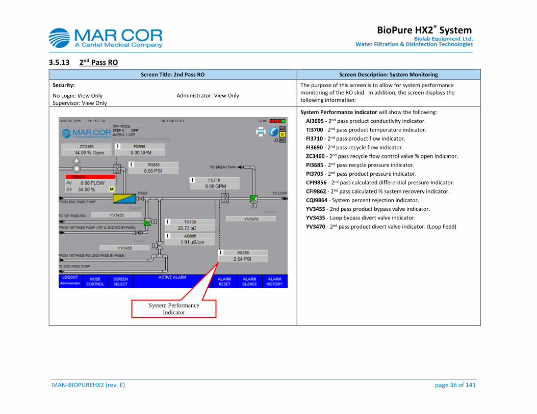
3.5.13 2nd Pass RO
Screen Title: 2nd Pass RO Screen Description: System Monitoring
Security: The purpose of this screen is to allow for system performance monitoring of the RO skid. In addition, the screen displays the following information:
No Login: View Only Supervisor: View Only
Administrator: View Only
System Performance Indicator will show the following:
AI3695 - 2nd pass product conductivity indicator.
TI3700 - 2nd pass product temperature indicator.
FI3710 - 2nd pass product flow indicator.
FI3690 - 2nd pass recycle flow indicator.
ZC3460 - 2nd pass recycle flow control valve % open indicator.
PI3685 - 2nd pass recycle pressure indicator.
PI3705 - 2nd pass product pressure indicator.
CPI9856 - 2nd pass calculated differential pressure Indicator.
CFI9862 - 2nd pass calculated % system recovery indicator.
CQI9864 - System percent rejection indicator.
YV3455 - 2nd pass product bypass valve indicator.
YV3435 - Loop bypass divert valve indicator.
YV3470 - 2nd pass product divert valve indicator. (Loop Feed)
System Performance
Indicator

MAN-BIOPUREHX2 (rev. E) page 37 of 141
BioPure HX2® System
3.5.14 Overview
Screen Title: Overview Screen Description: System Monitoring
Security: The purpose of this screen is to allow for system performance monitoring of the RO skid. In addition, the screen displays the following information:
No Login: View Only Supervisor: View Only
Administrator: View Only
NOTE: Due to the amount of information displayed most of the units of measure are not shown. Refer to the individual screens for more details.
System Performance Indicator will show the following information:
This is a general overview of the system piping and instrumentation. The previous screens provide details of each instrument and indicator as per section listed below:
Section: 3.5.7
Section: 3.5.8
Section: 3.5.9
Section: 3.5.10
Section: 3.5.11
Section: 3.5.12
Section: 3.5.13
System Performance
Indicator
MAN-BIOPUREHX2 (rev. E) page 38 of 141
BioPure HX2® System
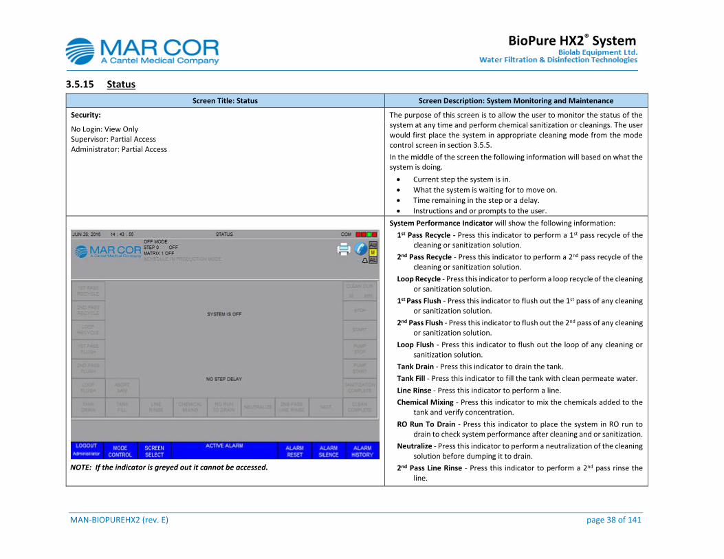
3.5.15 Status
Screen Title: Status Screen Description: System Monitoring and Maintenance
Security: The purpose of this screen is to allow the user to monitor the status of the system at any time and perform chemical sanitization or cleanings. The user would first place the system in appropriate cleaning mode from the mode control screen in section 3.5.5.
In the middle of the screen the following information will based on what the system is doing.
Current step the system is in.
What the system is waiting for to move on.
Time remaining in the step or a delay.
Instructions and or prompts to the user.
No Login: View Only Supervisor: Partial Access Administrator: Partial Access
NOTE: If the indicator is greyed out it cannot be accessed.
System Performance Indicator will show the following information:
1st Pass Recycle - Press this indicator to perform a 1st pass recycle of the cleaning or sanitization solution.
2nd Pass Recycle - Press this indicator to perform a 2nd pass recycle of the cleaning or sanitization solution.
Loop Recycle - Press this indicator to perform a loop recycle of the cleaning or sanitization solution.
1st Pass Flush - Press this indicator to flush out the 1st pass of any cleaning or sanitization solution.
2nd Pass Flush - Press this indicator to flush out the 2nd pass of any cleaning or sanitization solution.
Loop Flush - Press this indicator to flush out the loop of any cleaning or sanitization solution.
Tank Drain - Press this indicator to drain the tank.
Tank Fill - Press this indicator to fill the tank with clean permeate water.
Line Rinse - Press this indicator to perform a line.
Chemical Mixing - Press this indicator to mix the chemicals added to the tank and verify concentration.
RO Run To Drain - Press this indicator to place the system in RO run to drain to check system performance after cleaning and or sanitization.
Neutralize - Press this indicator to perform a neutralization of the cleaning solution before dumping it to drain.
2nd Pass Line Rinse - Press this indicator to perform a 2nd pass rinse the line.
MAN-BIOPUREHX2 (rev. E) page 39 of 141
BioPure HX2® System
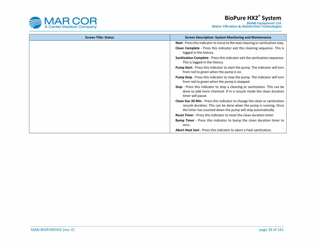
Screen Title: Status Screen Description: System Monitoring and Maintenance
Next - Press this indicator to move to the next cleaning or sanitization step.
Clean Complete - Press this indicator exit the cleaning sequence. This is logged in the history.
Sanitization Complete - Press this indicator exit the sanitization sequence. This is logged in the history.
Pump Start - Press this indicator to start the pump. The indicator will turn from red to green when the pump is on.
Pump Stop - Press this indicator to stop the pump. The indicator will turn from red to green when the pump is stopped.
Stop - Press this indicator to stop a cleaning or sanitization. This can be done to add more chemical. If in a recycle mode the clean duration timer will pause.
Clean Dur 20 Min - Press this indicator to change the clean or sanitization recycle duration. This can be done when the pump is running. Once the timer has counted down the pump will stop automatically.
Reset Timer - Press this indicator to reset the clean duration timer.
Bump Timer - Press this indicator to bump the clean duration timer to zero.
Abort Heat Sani - Press this indicator to abort a heat sanitization.
MAN-BIOPUREHX2 (rev. E) page 40 of 141
BioPure HX2® System
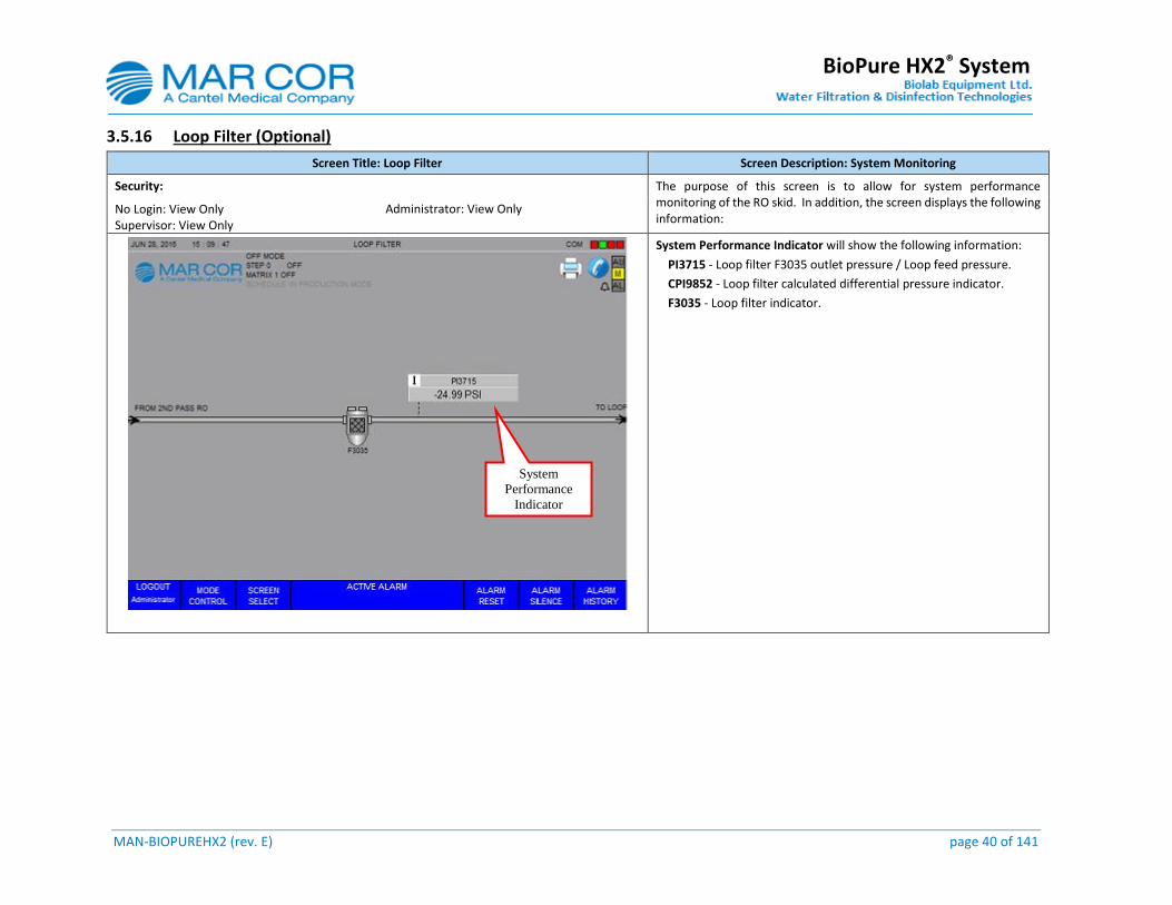
3.5.16 Loop Filter (Optional)
Screen Title: Loop Filter Screen Description: System Monitoring
Security: The purpose of this screen is to allow for system performance monitoring of the RO skid. In addition, the screen displays the following information:
No Login: View Only Supervisor: View Only
Administrator: View Only
System Performance Indicator will show the following information:
PI3715 - Loop filter F3035 outlet pressure / Loop feed pressure.
CPI9852 - Loop filter calculated differential pressure indicator.
F3035 - Loop filter indicator.
System
Performance
Indicator
MAN-BIOPUREHX2 (rev. E) page 41 of 141
BioPure HX2® System
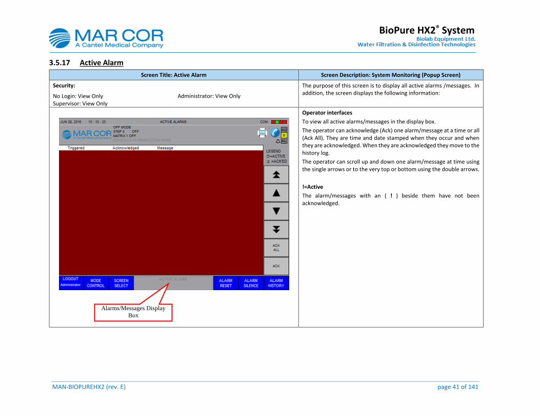
3.5.17 Active Alarm
Screen Title: Active Alarm Screen Description: System Monitoring (Popup Screen)
Security: The purpose of this screen is to display all active alarms /messages. In addition, the screen displays the following information:
No Login: View Only Supervisor: View Only
Administrator: View Only
Operator interfaces
To view all active alarms/messages in the display box.
The operator can acknowledge (Ack) one alarm/message at a time or all (Ack All). They are time and date stamped when they occur and when they are acknowledged. When they are acknowledged they move to the history log.
The operator can scroll up and down one alarm/message at time using the single arrows or to the very top or bottom using the double arrows.
!=Active
The alarm/messages with an ( ! ) beside them have not been acknowledged.
Alarms/Messages Display
Box

MAN-BIOPUREHX2 (rev. E) page 42 of 141
BioPure HX2® System
3.5.18 Alarm History
Screen Title: Alarm History Screen Description: System Monitoring (Popup Screen)
Security: The purpose of this screen is to display all the alarms/messages. In addition, the screen displays the following information:
No Login: View Only Supervisor: View Only
Administrator: View Only
NOTE: The recorded events cannot be erased manually.
Operator interfaces
To view all history alarm/message display box.
The operator can view the history of alarms/messages. They are time and date stamped when they occurred.
The operator can acknowledge (Ack) one alarm/message at a time or all (Ack All). They are time and date stamped when they occur and when they are acknowledged.
The operator can scroll up and down one alarm/message at time using the single arrows or to the very top or bottom using the double arrows.
!=Active
The alarm/messages with an ( ! ) beside them have not been acknowledged.
*=Ack’ed
The alarm/messages with a ( * ) beside them have been acknowledged.
Based on the HMI internal memory capacity the history log can record approximately 4,000 events including the heat sanitization and cleaning history. Once full, the next event recorded will in turn erase the oldest event recorded.
Alarms/Messages Display Box
MAN-BIOPUREHX2 (rev. E) page 43 of 141
BioPure HX2® System
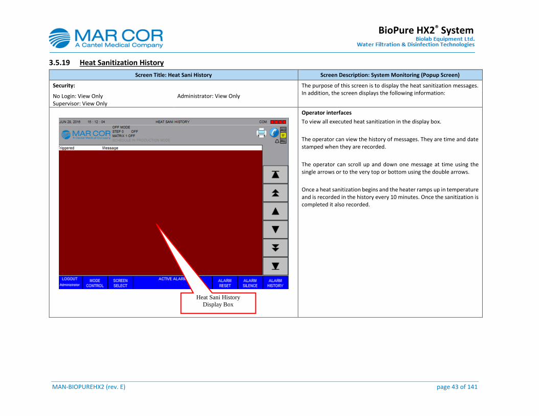
3.5.19 Heat Sanitization History
Screen Title: Heat Sani History Screen Description: System Monitoring (Popup Screen)
Security: The purpose of this screen is to display the heat sanitization messages. In addition, the screen displays the following information:
No Login: View Only Supervisor: View Only
Administrator: View Only
Operator interfaces
To view all executed heat sanitization in the display box.
The operator can view the history of messages. They are time and date stamped when they are recorded.
The operator can scroll up and down one message at time using the single arrows or to the very top or bottom using the double arrows.
Once a heat sanitization begins and the heater ramps up in temperature and is recorded in the history every 10 minutes. Once the sanitization is completed it also recorded.
Heat Sani History
Display Box

MAN-BIOPUREHX2 (rev. E) page 44 of 141
BioPure HX2® System
3.5.20 Chemical Cleaning History
Screen Title: Chem Clean History Screen Description: System Monitoring (Popup Screen)
Security: The purpose of this screen is to display all cleaning messages. In addition, the screen displays the following information:
No Login: View Only Supervisor: View Only
Administrator: View Only
Operator interfaces
To view all executed cleanings in the display box.
The operator can view the history of messages. They are time and date stamped when they are recorded.
The operator can scroll up and down one message at time using the single arrows or to the very top or bottom using the double arrows.
The start and completion of the chemical clean are recorded in the history.
Chemical Clean
Display Box
MAN-BIOPUREHX2 (rev. E) page 45 of 141
BioPure HX2® System
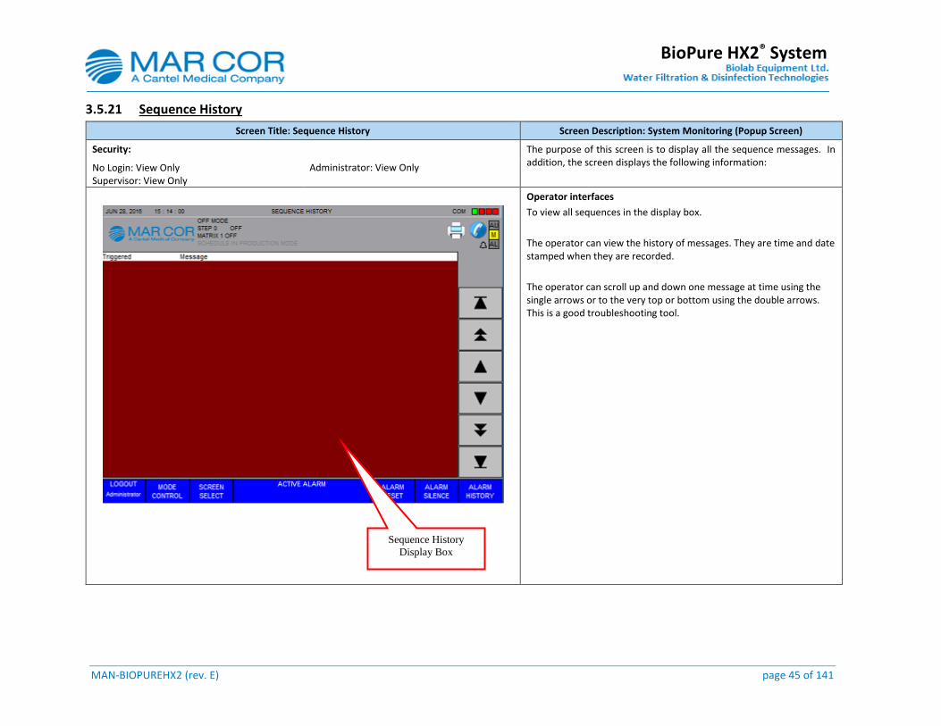
3.5.21 Sequence History
Screen Title: Sequence History Screen Description: System Monitoring (Popup Screen)
Security: The purpose of this screen is to display all the sequence messages. In addition, the screen displays the following information:
No Login: View Only Supervisor: View Only
Administrator: View Only
Operator interfaces
To view all sequences in the display box.
The operator can view the history of messages. They are time and date stamped when they are recorded.
The operator can scroll up and down one message at time using the single arrows or to the very top or bottom using the double arrows. This is a good troubleshooting tool.
Sequence History
Display Box

MAN-BIOPUREHX2 (rev. E) page 46 of 141
BioPure HX2® System
3.5.22 Setpoint 1
Screen Title: Setpoint 1 Screen Description: System Monitoring & Setpoint Adjustment
Security: The purpose of this screen is to allow for viewing or changing system setpoints. In addition, the screen displays the following information:
No Login: View Only Supervisor: View Only With Limited Access To Setpoint Administrator: View Only With Limited Access To Setpoint
Operator Interfaces
To adjust any setpoints on this screen, press the desired “Setpoint Box” and then change the entry as required. A numerical entry keypad will appear and it will only accept numbers with working range indicated at the top of keypad.
Softener Configuration
Choice between: Duplex (Parallel) and Single
Default: Single
If Duplex is selected the system will remain in operation if one of the softeners regenerates via an open signal (dry contact).
If Single is selected the system will go into off mode once the softener regeneration is complete it will go back into the mode it was in prior to the softener regenerating.
NOTE: This is set up at the factory or 1st time start-up.
UA1850 General Pre-treatment Interlock RO On/Off
Choice between: RO on and RO off
Default: RO Off
If RO On is selected the system will remain in operation if the general pre-treatment device sends an open signal (dry contact) indicating it is out of service, general interlock or an alarm.
If RO Off is selected the system will go into off mode if the general pre-treatment device sends an open signal (dry contact) and will go back into the mode it was in prior, once the signal closes.
NOTE: This is set up at the factory or the 1st time start-up. General pre-treatment devices could be a chemical feed pump or multi-layer filter…
Setpoint Boxes
MAN-BIOPUREHX2 (rev. E) page 47 of 141
BioPure HX2® System
Screen Title: Setpoint 1 Screen Description: System Monitoring & Setpoint Adjustment
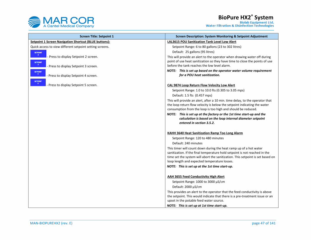
Setpoint 1 Screen Navigation Shortcut (BLUE buttons):
Quick access to view different setpoint setting screens.
- Press to display Setpoint 2 screen.
- Press to display Setpoint 3 screen.
- Press to display Setpoint 4 screen.
- Press to display Setpoint 5 screen.
LAL3615 POU Sanitization Tank Level Low Alert
Setpoint Range: 6 to 80 gallons (23 to 302 litres)
Default: 25 gallons (95 litres)
This will provide an alert to the operator when drawing water off during point of use heat sanitization so they have time to close the points of use before the tank reaches the low level alarm.
NOTE: This is set up based on the operator water volume requirement for a POU heat sanitization.
CAL 9874 Loop Return Flow Velocity Low Alert
Setpoint Range: 1.0 to 10.0 fts (0.305 to 3.05 mps)
Default: 1.5 fts (0.457 mps)
This will provide an alert, after a 10 min. time delay, to the operator that the loop return flow velocity is below the setpoint indicating the water consumption from the loop is too high and should be reduced.
NOTE: This is set up at the factory or the 1st time start-up and the calculation is based on the loop internal diameter setpoint entered in section 3.5.2.
KAHH 3640 Heat Sanitization Ramp Too Long Alarm
Setpoint Range: 120 to 480 minutes
Default: 240 minutes
This timer will count down during the heat ramp up of a hot water sanitization. If the final temperature hold setpoint is not reached in the time set the system will abort the sanitization. This setpoint is set based on loop length and expected temperature losses.
NOTE: This is set up at the 1st time start-up.
AAH 3655 Feed Conductivity High Alert
Setpoint Range: 1000 to 3000 µS/cm
Default: 2000 µS/cm
This provides an alert to the operator that the feed conductivity is above the setpoint. This would indicate that there is a pre-treatment issue or an upset in the potable feed water source.
NOTE: This is set up at 1st time start-up.

MAN-BIOPUREHX2 (rev. E) page 48 of 141
BioPure HX2® System
Screen Title: Setpoint 1 Screen Description: System Monitoring & Setpoint Adjustment
CAH 9854 1st Pass Membrane Pressure Differential High Alert
Setpoint Range: 5 to 60 psig
Default: 10 psig
This provides an alert to the operator the 1st pass membrane pressure differential is above the setpoint. This could indicate that a cleaning of the first pass membrane is required.
NOTE: This is set up at the 1st time start-up and after every cleaning. It is set to 15% above the normal operating 1st pass membrane pressure differential.
AAH 3665 1st Product Conductivity High Alert
Setpoint Range: 1.0 to 100.0 µS/cm
Default: 10.0 µS/cm
This provides an alert to the operator that the 1st pass product conductivity is above the setpoint. This could indicate that a cleaning of the first pass membrane is required or the membranes need to be replaced.
NOTE: This is set up at 1st time start-up, after a cleaning or as the membranes age.
CAH 9856 2nd Pass Membrane Pressure Differential High Alert
Setpoint Range: 5 to 60 psig
Default: 10 psig
This provides an alert to the operator the 2nd pass membrane pressure differential is above the setpoint. This could indicate that a cleaning of the first pass membrane is required.
NOTE: This is set up at 1st time start-up and after every cleaning. It is set to 15% above the normal operating 2nd pass membrane pressure differential
MAN-BIOPUREHX2 (rev. E) page 49 of 141
BioPure HX2® System
3.5.23 Setpoint 2
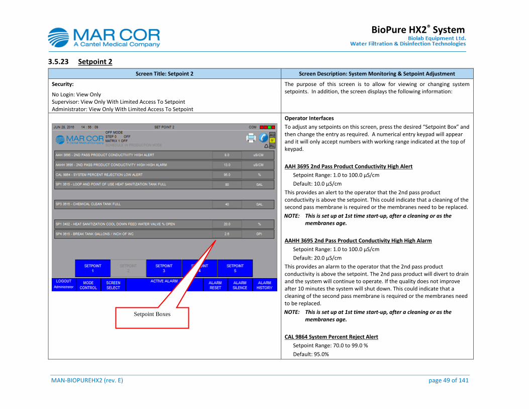
Screen Title: Setpoint 2 Screen Description: System Monitoring & Setpoint Adjustment
Security: The purpose of this screen is to allow for viewing or changing system setpoints. In addition, the screen displays the following information:
No Login: View Only Supervisor: View Only With Limited Access To Setpoint Administrator: View Only With Limited Access To Setpoint
Operator Interfaces
To adjust any setpoints on this screen, press the desired “Setpoint Box” and then change the entry as required. A numerical entry keypad will appear and it will only accept numbers with working range indicated at the top of keypad.
AAH 3695 2nd Pass Product Conductivity High Alert
Setpoint Range: 1.0 to 100.0 µS/cm
Default: 10.0 µS/cm
This provides an alert to the operator that the 2nd pass product conductivity is above the setpoint. This could indicate that a cleaning of the second pass membrane is required or the membranes need to be replaced.
NOTE: This is set up at 1st time start-up, after a cleaning or as the membranes age.
AAHH 3695 2nd Pass Product Conductivity High High Alarm
Setpoint Range: 1.0 to 100.0 µS/cm
Default: 20.0 µS/cm
This provides an alarm to the operator that the 2nd pass product conductivity is above the setpoint. The 2nd pass product will divert to drain and the system will continue to operate. If the quality does not improve after 10 minutes the system will shut down. This could indicate that a cleaning of the second pass membrane is required or the membranes need to be replaced.
NOTE: This is set up at 1st time start-up, after a cleaning or as the membranes age.
CAL 9864 System Percent Reject Alert
Setpoint Range: 70.0 to 99.0 %
Default: 95.0%
Setpoint Boxes
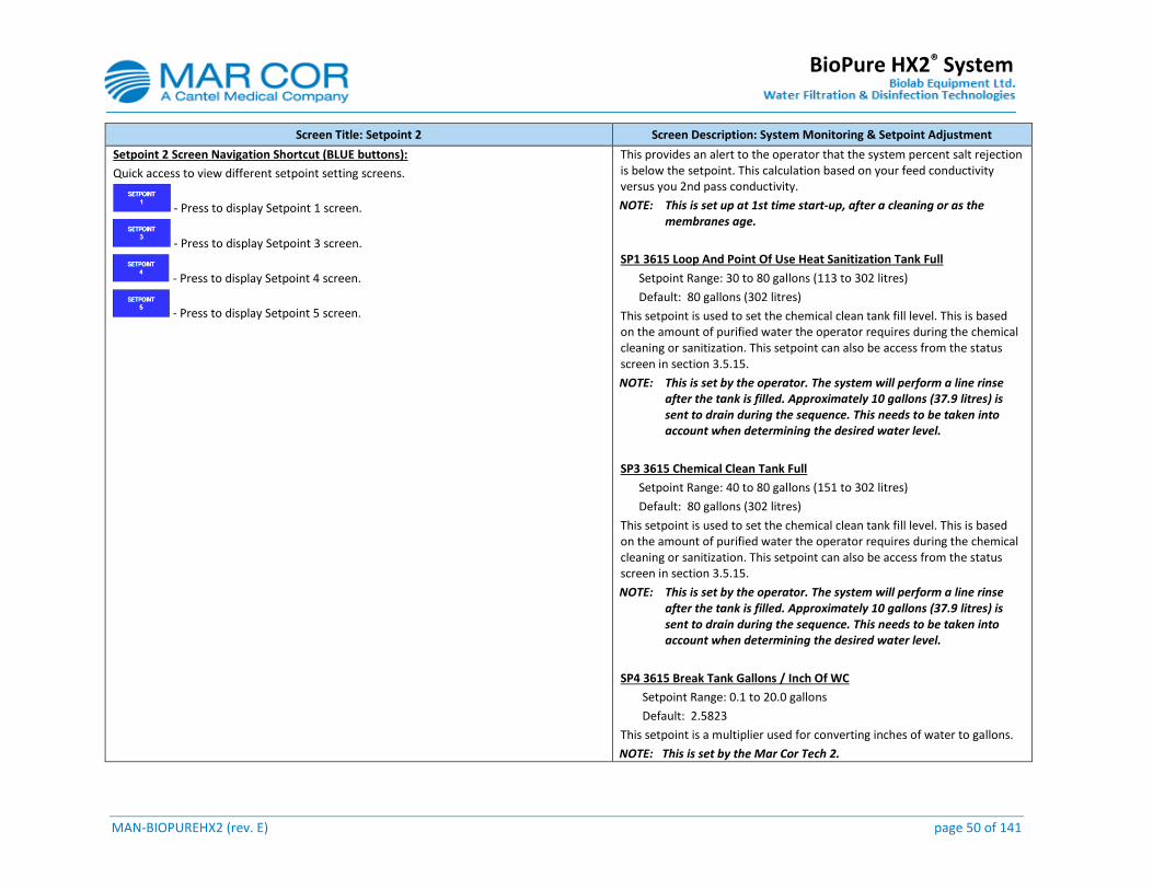
MAN-BIOPUREHX2 (rev. E) page 50 of 141
BioPure HX2® System
Screen Title: Setpoint 2 Screen Description: System Monitoring & Setpoint Adjustment
Setpoint 2 Screen Navigation Shortcut (BLUE buttons):
Quick access to view different setpoint setting screens.
- Press to display Setpoint 1 screen.
- Press to display Setpoint 3 screen.
- Press to display Setpoint 4 screen.
- Press to display Setpoint 5 screen.
This provides an alert to the operator that the system percent salt rejection is below the setpoint. This calculation based on your feed conductivity versus you 2nd pass conductivity.
NOTE: This is set up at 1st time start-up, after a cleaning or as the membranes age.
SP1 3615 Loop And Point Of Use Heat Sanitization Tank Full
Setpoint Range: 30 to 80 gallons (113 to 302 litres)
Default: 80 gallons (302 litres)
This setpoint is used to set the chemical clean tank fill level. This is based on the amount of purified water the operator requires during the chemical cleaning or sanitization. This setpoint can also be access from the status screen in section 3.5.15.
NOTE: This is set by the operator. The system will perform a line rinse after the tank is filled. Approximately 10 gallons (37.9 litres) is sent to drain during the sequence. This needs to be taken into account when determining the desired water level.
SP3 3615 Chemical Clean Tank Full
Setpoint Range: 40 to 80 gallons (151 to 302 litres)
Default: 80 gallons (302 litres)
This setpoint is used to set the chemical clean tank fill level. This is based on the amount of purified water the operator requires during the chemical cleaning or sanitization. This setpoint can also be access from the status screen in section 3.5.15.
NOTE: This is set by the operator. The system will perform a line rinse after the tank is filled. Approximately 10 gallons (37.9 litres) is sent to drain during the sequence. This needs to be taken into account when determining the desired water level.
SP4 3615 Break Tank Gallons / Inch Of WC
Setpoint Range: 0.1 to 20.0 gallons
Default: 2.5823
This setpoint is a multiplier used for converting inches of water to gallons.
NOTE: This is set by the Mar Cor Tech 2.

MAN-BIOPUREHX2 (rev. E) page 51 of 141
BioPure HX2® System
Screen Title: Setpoint 2 Screen Description: System Monitoring & Setpoint Adjustment
SP1 3402 Heat Sanitization Cool Down Feed Water Valve % Open
Setpoint Range: 0 to 100 % valve opened
Default: 20 %
This setpoint is used to set the valve opening to control cool. It is an upper limit setting.
NOTE: This is set by the supervisor.
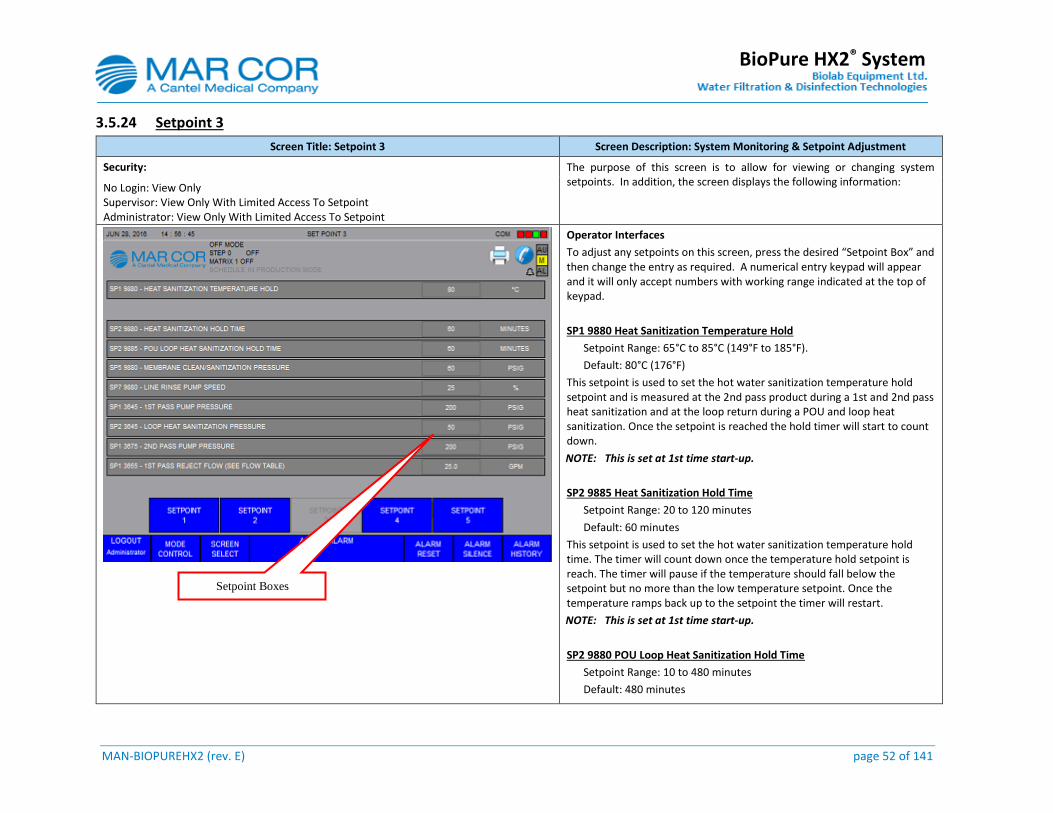
MAN-BIOPUREHX2 (rev. E) page 52 of 141
BioPure HX2® System
3.5.24 Setpoint 3
Screen Title: Setpoint 3 Screen Description: System Monitoring & Setpoint Adjustment
Security: The purpose of this screen is to allow for viewing or changing system setpoints. In addition, the screen displays the following information:
No Login: View Only Supervisor: View Only With Limited Access To Setpoint Administrator: View Only With Limited Access To Setpoint
Operator Interfaces
To adjust any setpoints on this screen, press the desired “Setpoint Box” and then change the entry as required. A numerical entry keypad will appear and it will only accept numbers with working range indicated at the top of keypad.
SP1 9880 Heat Sanitization Temperature Hold
Setpoint Range: 65°C to 85°C (149°F to 185°F).
Default: 80°C (176°F)
This setpoint is used to set the hot water sanitization temperature hold setpoint and is measured at the 2nd pass product during a 1st and 2nd pass heat sanitization and at the loop return during a POU and loop heat sanitization. Once the setpoint is reached the hold timer will start to count down.
NOTE: This is set at 1st time start-up.
SP2 9885 Heat Sanitization Hold Time
Setpoint Range: 20 to 120 minutes
Default: 60 minutes
This setpoint is used to set the hot water sanitization temperature hold time. The timer will count down once the temperature hold setpoint is reach. The timer will pause if the temperature should fall below the setpoint but no more than the low temperature setpoint. Once the temperature ramps back up to the setpoint the timer will restart.
NOTE: This is set at 1st time start-up.
SP2 9880 POU Loop Heat Sanitization Hold Time
Setpoint Range: 10 to 480 minutes
Default: 480 minutes
Setpoint Boxes
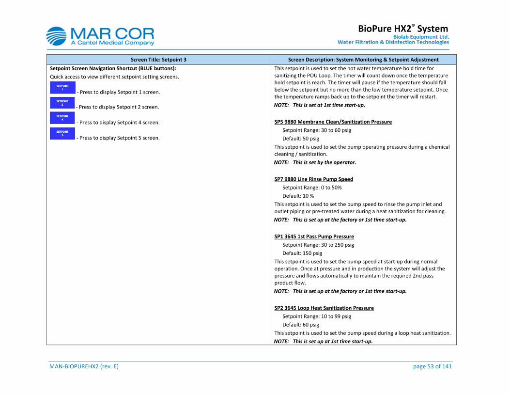
MAN-BIOPUREHX2 (rev. E) page 53 of 141
BioPure HX2® System
Screen Title: Setpoint 3 Screen Description: System Monitoring & Setpoint Adjustment
Setpoint Screen Navigation Shortcut (BLUE buttons):
Quick access to view different setpoint setting screens.
- Press to display Setpoint 1 screen.
- Press to display Setpoint 2 screen.
- Press to display Setpoint 4 screen.
- Press to display Setpoint 5 screen.
This setpoint is used to set the hot water temperature hold time for sanitizing the POU Loop. The timer will count down once the temperature hold setpoint is reach. The timer will pause if the temperature should fall below the setpoint but no more than the low temperature setpoint. Once the temperature ramps back up to the setpoint the timer will restart.
NOTE: This is set at 1st time start-up.
SP5 9880 Membrane Clean/Sanitization Pressure
Setpoint Range: 30 to 60 psig
Default: 50 psig
This setpoint is used to set the pump operating pressure during a chemical cleaning / sanitization.
NOTE: This is set by the operator.
SP7 9880 Line Rinse Pump Speed
Setpoint Range: 0 to 50%
Default: 10 %
This setpoint is used to set the pump speed to rinse the pump inlet and outlet piping or pre-treated water during a heat sanitization for cleaning.
NOTE: This is set up at the factory or 1st time start-up.
SP1 3645 1st Pass Pump Pressure
Setpoint Range: 30 to 250 psig
Default: 150 psig
This setpoint is used to set the pump speed at start-up during normal operation. Once at pressure and in production the system will adjust the pressure and flows automatically to maintain the required 2nd pass product flow.
NOTE: This is set up at the factory or 1st time start-up.
SP2 3645 Loop Heat Sanitization Pressure
Setpoint Range: 10 to 99 psig
Default: 60 psig
This setpoint is used to set the pump speed during a loop heat sanitization.
NOTE: This is set up at 1st time start-up.
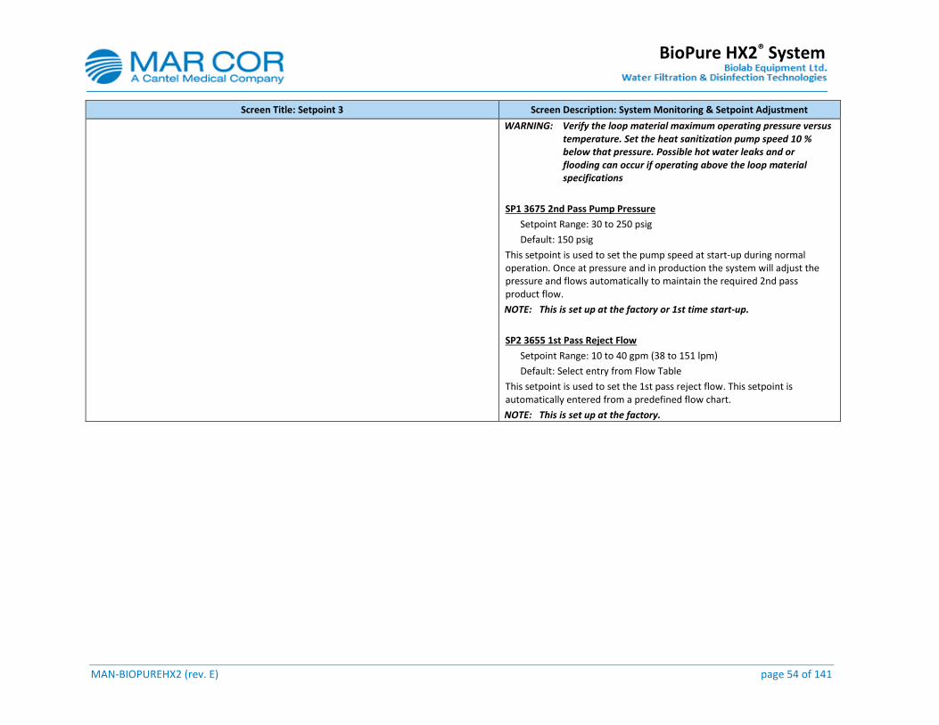
MAN-BIOPUREHX2 (rev. E) page 54 of 141
BioPure HX2® System
Screen Title: Setpoint 3 Screen Description: System Monitoring & Setpoint Adjustment
WARNING: Verify the loop material maximum operating pressure versus temperature. Set the heat sanitization pump speed 10 % below that pressure. Possible hot water leaks and or flooding can occur if operating above the loop material specifications
SP1 3675 2nd Pass Pump Pressure
Setpoint Range: 30 to 250 psig
Default: 150 psig
This setpoint is used to set the pump speed at start-up during normal operation. Once at pressure and in production the system will adjust the pressure and flows automatically to maintain the required 2nd pass product flow.
NOTE: This is set up at the factory or 1st time start-up.
SP2 3655 1st Pass Reject Flow
Setpoint Range: 10 to 40 gpm (38 to 151 lpm)
Default: Select entry from Flow Table
This setpoint is used to set the 1st pass reject flow. This setpoint is automatically entered from a predefined flow chart.
NOTE: This is set up at the factory.

MAN-BIOPUREHX2 (rev. E) page 55 of 141
BioPure HX2® System
3.5.25 Setpoint 4
Screen Title: Setpoint 4 Screen Description: System Monitoring & Setpoint Adjustment
Security: The purpose of this screen is to allow for monitoring of system setpoints. In addition, the screen displays the following information:
No Login: View Only Supervisor: View Only With Limited Access To Setpoint Administrator: View Only With Limited Access To Setpoint
Operator Interfaces
To adjust any setpoints on this screen, press the desired “Setpoint Box” and then change the entry as required. A numerical entry keypad will appear and it will only accept numbers with working range indicated at the top of keypad.
SP1 3660 1st Pass Reject Drain Flow
Setpoint Range: 1 to 20 gpm (4 to 76 lpm)
Default: Select entry from Flow Table
This setpoint is used to set the 1st pass reject drain flow at initial start-up. This setpoint is automatically entered from a predefined flow chart.
NOTE: This is set up at the factory.
SP1 3690 2nd Pass Recycle Flow
Setpoint Range: 1 to 20 gpm (4 to 76 lpm)
Default: Select entry from Flow Table
This setpoint is used to set the 2nd pass recycle flow at initial start-up. This setpoint is automatically entered from a predefined flow chart.
NOTE: This is set up at the factory.
SP1 3710 2nd Pass Maximum Product Flow
This setpoint is used to set the 1st pass maximum product flow. This setpoint is automatically entered from a predefined flow chart.
NOTE: This is set up at the factory.
Feed Low Pressure Auto Retry
Setpoint Range: 0 to 5
Default: 0
Setpoint Boxes
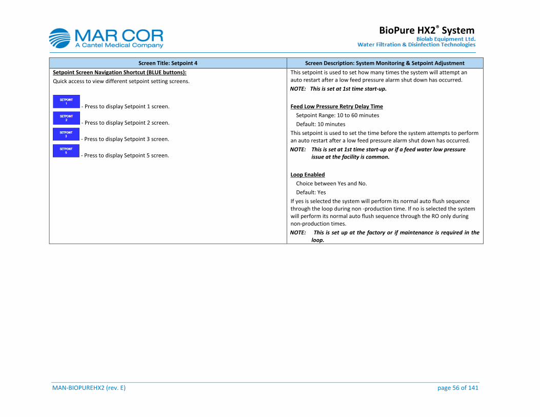
MAN-BIOPUREHX2 (rev. E) page 56 of 141
BioPure HX2® System
Screen Title: Setpoint 4 Screen Description: System Monitoring & Setpoint Adjustment
Setpoint Screen Navigation Shortcut (BLUE buttons):
Quick access to view different setpoint setting screens.
- Press to display Setpoint 1 screen.
- Press to display Setpoint 2 screen.
- Press to display Setpoint 3 screen.
- Press to display Setpoint 5 screen.
This setpoint is used to set how many times the system will attempt an auto restart after a low feed pressure alarm shut down has occurred.
NOTE: This is set at 1st time start-up.
Feed Low Pressure Retry Delay Time
Setpoint Range: 10 to 60 minutes
Default: 10 minutes
This setpoint is used to set the time before the system attempts to perform an auto restart after a low feed pressure alarm shut down has occurred.
NOTE: This is set at 1st time start-up or if a feed water low pressure issue at the facility is common.
Loop Enabled
Choice between Yes and No.
Default: Yes
If yes is selected the system will perform its normal auto flush sequence through the loop during non -production time. If no is selected the system will perform its normal auto flush sequence through the RO only during non-production times.
NOTE: This is set up at the factory or if maintenance is required in the loop.
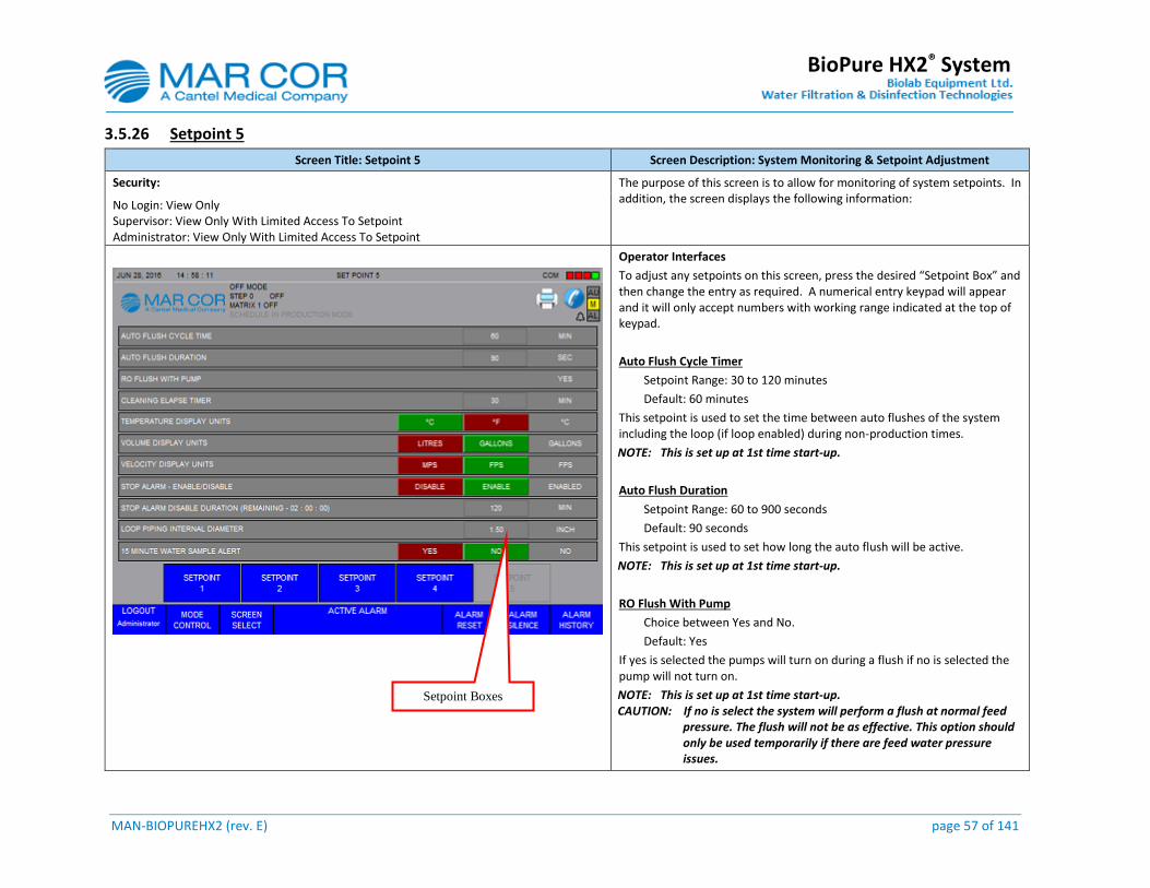
MAN-BIOPUREHX2 (rev. E) page 57 of 141
BioPure HX2® System
3.5.26 Setpoint 5
Screen Title: Setpoint 5 Screen Description: System Monitoring & Setpoint Adjustment
Security: The purpose of this screen is to allow for monitoring of system setpoints. In addition, the screen displays the following information:
No Login: View Only Supervisor: View Only With Limited Access To Setpoint Administrator: View Only With Limited Access To Setpoint
Operator Interfaces
To adjust any setpoints on this screen, press the desired “Setpoint Box” and then change the entry as required. A numerical entry keypad will appear and it will only accept numbers with working range indicated at the top of keypad.
Auto Flush Cycle Timer
Setpoint Range: 30 to 120 minutes
Default: 60 minutes
This setpoint is used to set the time between auto flushes of the system including the loop (if loop enabled) during non-production times.
NOTE: This is set up at 1st time start-up.
Auto Flush Duration
Setpoint Range: 60 to 900 seconds
Default: 90 seconds
This setpoint is used to set how long the auto flush will be active.
NOTE: This is set up at 1st time start-up.
RO Flush With Pump
Choice between Yes and No.
Default: Yes
If yes is selected the pumps will turn on during a flush if no is selected the pump will not turn on.
NOTE: This is set up at 1st time start-up. CAUTION: If no is select the system will perform a flush at normal feed
pressure. The flush will not be as effective. This option should only be used temporarily if there are feed water pressure issues.
Setpoint Boxes
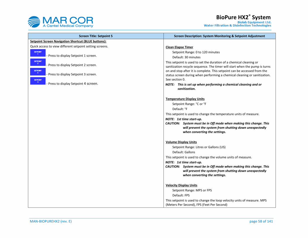
MAN-BIOPUREHX2 (rev. E) page 58 of 141
BioPure HX2® System
Screen Title: Setpoint 5 Screen Description: System Monitoring & Setpoint Adjustment
Setpoint Screen Navigation Shortcut (BLUE buttons):
Quick access to view different setpoint setting screens.
- Press to display Setpoint 1 screen.
- Press to display Setpoint 2 screen.
- Press to display Setpoint 3 screen.
- Press to display Setpoint 4 screen.
Clean Elapse Timer
Setpoint Range: 0 to 120 minutes
Default: 30 minutes
This setpoint is used to set the duration of a chemical cleaning or sanitization recycle sequence. The timer will start when the pump is turns on and stop after it is complete. This setpoint can be accessed from the status screen during when performing a chemical cleaning or sanitization. See section 0.
NOTE: This is set up when performing a chemical cleaning and or sanitization.
Temperature Display Units
Setpoint Range: °C or °F
Default: °F
This setpoint is used to change the temperature units of measure.
NOTE: 1st time start-up. CAUTION: System must be in Off mode when making this change. This
will prevent the system from shutting down unexpectedly when converting the settings.
Volume Display Units
Setpoint Range: Litres or Gallons (US)
Default: Gallons
This setpoint is used to change the volume units of measure.
NOTE: 1st time start-up. CAUTION: System must be in Off mode when making this change. This
will prevent the system from shutting down unexpectedly when converting the settings.
Velocity Display Units
Setpoint Range: MPS or FPS
Default: FPS
This setpoint is used to change the loop velocity units of measure. MPS (Meters Per Second), FPS (Feet Per Second)
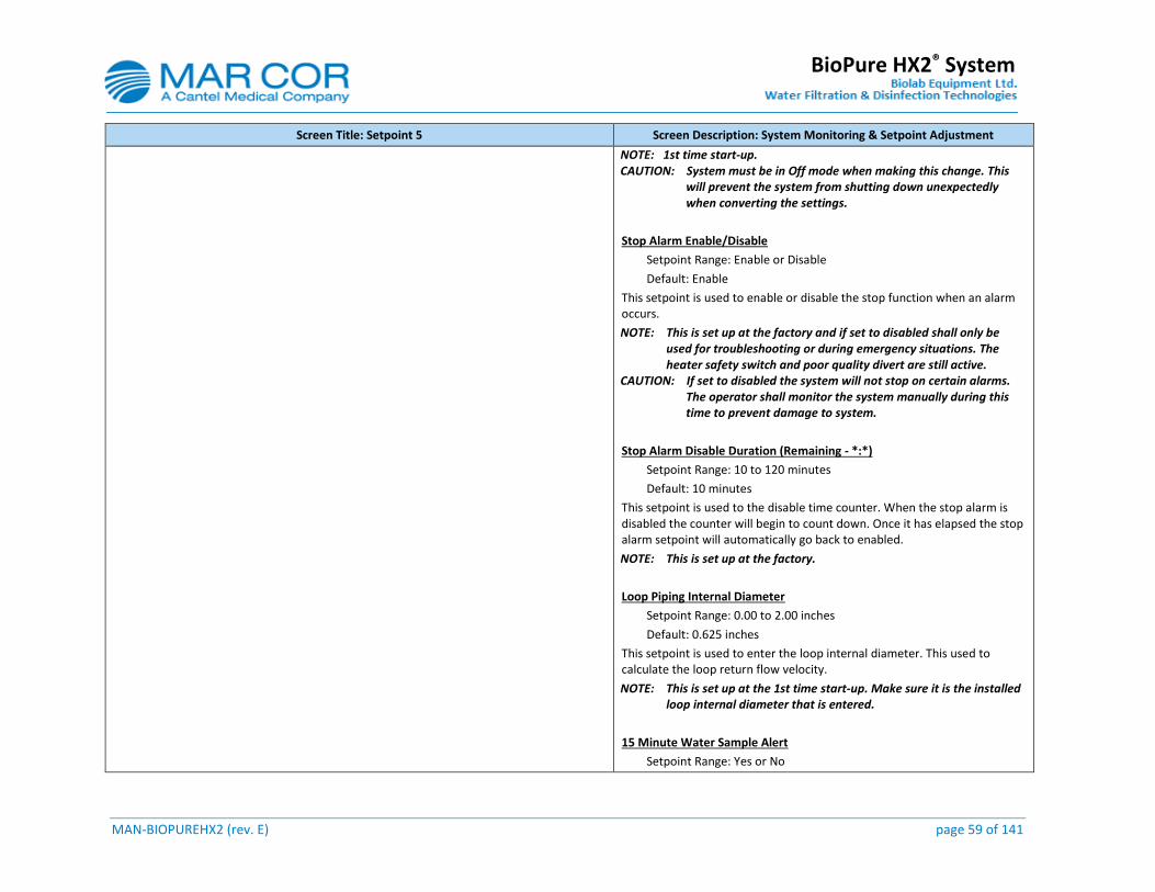
MAN-BIOPUREHX2 (rev. E) page 59 of 141
BioPure HX2® System
Screen Title: Setpoint 5 Screen Description: System Monitoring & Setpoint Adjustment
NOTE: 1st time start-up. CAUTION: System must be in Off mode when making this change. This
will prevent the system from shutting down unexpectedly when converting the settings.
Stop Alarm Enable/Disable
Setpoint Range: Enable or Disable
Default: Enable
This setpoint is used to enable or disable the stop function when an alarm occurs.
NOTE: This is set up at the factory and if set to disabled shall only be used for troubleshooting or during emergency situations. The heater safety switch and poor quality divert are still active.
CAUTION: If set to disabled the system will not stop on certain alarms. The operator shall monitor the system manually during this time to prevent damage to system.
Stop Alarm Disable Duration (Remaining - *:*)
Setpoint Range: 10 to 120 minutes
Default: 10 minutes
This setpoint is used to the disable time counter. When the stop alarm is disabled the counter will begin to count down. Once it has elapsed the stop alarm setpoint will automatically go back to enabled.
NOTE: This is set up at the factory.
Loop Piping Internal Diameter
Setpoint Range: 0.00 to 2.00 inches
Default: 0.625 inches
This setpoint is used to enter the loop internal diameter. This used to calculate the loop return flow velocity.
NOTE: This is set up at the 1st time start-up. Make sure it is the installed loop internal diameter that is entered.
15 Minute Water Sample Alert
Setpoint Range: Yes or No
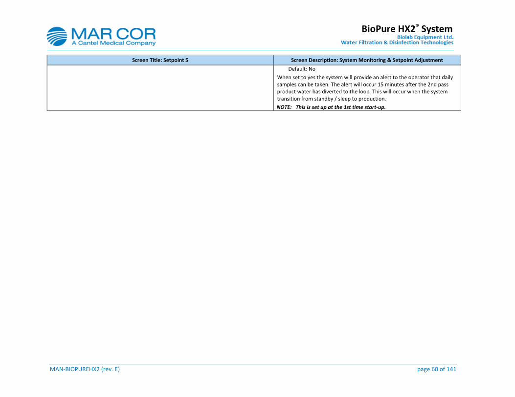
MAN-BIOPUREHX2 (rev. E) page 60 of 141
BioPure HX2® System
Screen Title: Setpoint 5 Screen Description: System Monitoring & Setpoint Adjustment
Default: No
When set to yes the system will provide an alert to the operator that daily samples can be taken. The alert will occur 15 minutes after the 2nd pass product water has diverted to the loop. This will occur when the system transition from standby / sleep to production.
NOTE: This is set up at the 1st time start-up.

MAN-BIOPUREHX2 (rev. E) page 61 of 141
BioPure HX2® System
3.5.27 Production and Heat Sanitization Scheduler
Screen Title: Schedule Screen Description: Production and Heat Sanitization Schedule Setting
Security: The purpose of this screen is to allow user to pre-set automatic system production and heat sanitization schedules.
No Login: View Only Supervisor: Full Access
Administrator: Full Access
CAUTION: System must be in Off mode when making changes to the schedule. This will prevent the system from shutting down unexpectedly.
NOTE: If the stop production time is changed while the system is running and the time set is before the original stop time the system will continue to operate until the next stop time in the next day.
Scheduling Procedure
Place the system in Off mode when making schedule changes.
Press the desired Schedule Indicator to:
Select DAY of the week to ENABLED or DISABLED production schedule and heat sanitization schedule.
Set time of the day to start production and heat sanitization (i.e. Enter hour and minute).
Set time of the day to stop production and heat sanitization (i.e. Enter hour and minute).
Only ONE sanitization sequence can be executed in a day. Available sequences are as follow:
= Heat sanitize 1st pass RO only
= Heat sanitize 2nd pass RO only
= Heat sanitize loop only
= Heat sanitize 1st pass RO, 2nd pass RO
= Heat sanitize loop and point of use.
= Heat sanitize 1st pass RO, 2nd pass RO, loop.
If multiple sequences are set, only one sequence will heat sanitize at a time followed by the next one.
System must be in Sleep (Non-Production) or Standby for a heat sanitization to occur.
Multi-selection Button Schedule Indicator
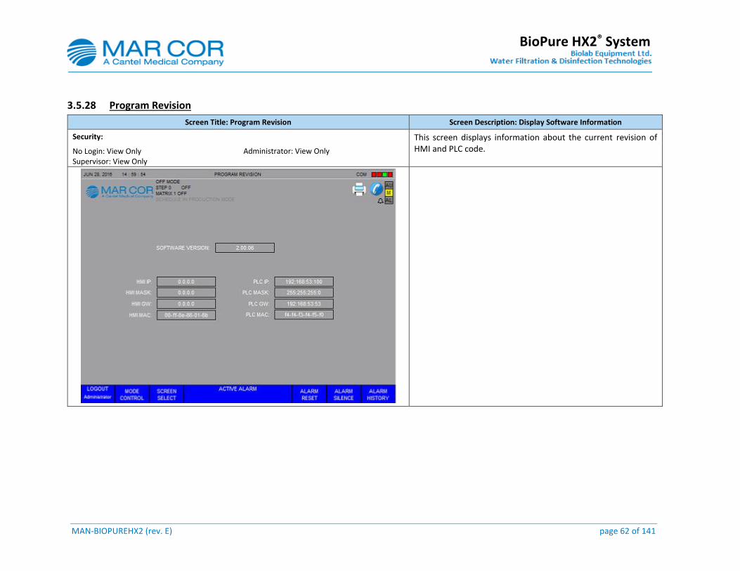
MAN-BIOPUREHX2 (rev. E) page 62 of 141
BioPure HX2® System
3.5.28 Program Revision
Screen Title: Program Revision Screen Description: Display Software Information
Security: This screen displays information about the current revision of HMI and PLC code. No Login: View Only
Supervisor: View Only Administrator: View Only
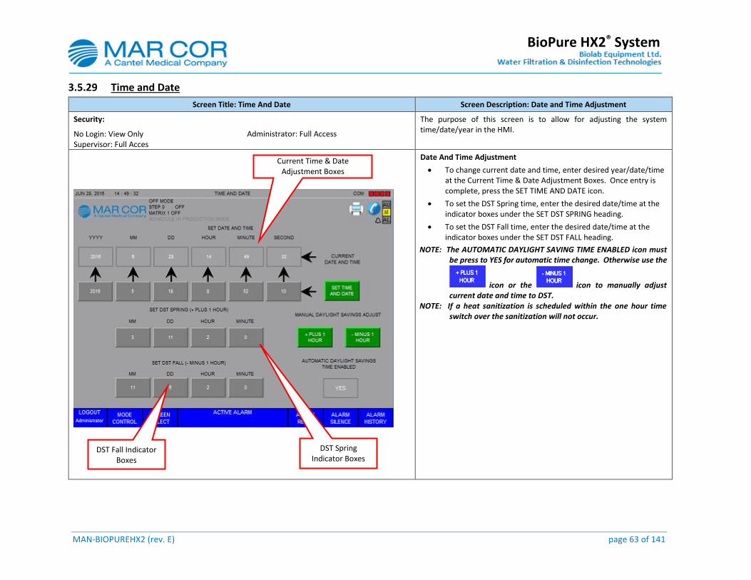
MAN-BIOPUREHX2 (rev. E) page 63 of 141
BioPure HX2® System
3.5.29 Time and Date
Screen Title: Time And Date Screen Description: Date and Time Adjustment
Security: The purpose of this screen is to allow for adjusting the system time/date/year in the HMI.
No Login: View Only Supervisor: Full Acces
Administrator: Full Access
Date And Time Adjustment
To change current date and time, enter desired year/date/time at the Current Time & Date Adjustment Boxes. Once entry is complete, press the SET TIME AND DATE icon.
To set the DST Spring time, enter the desired date/time at the indicator boxes under the SET DST SPRING heading.
To set the DST Fall time, enter the desired date/time at the indicator boxes under the SET DST FALL heading.
NOTE: The AUTOMATIC DAYLIGHT SAVING TIME ENABLED icon must be press to YES for automatic time change. Otherwise use the
icon or the icon to manually adjust current date and time to DST.
NOTE: If a heat sanitization is scheduled within the one hour time switch over the sanitization will not occur.
DST Spring Indicator Boxes
DST Fall Indicator Boxes
Current Time & Date Adjustment Boxes
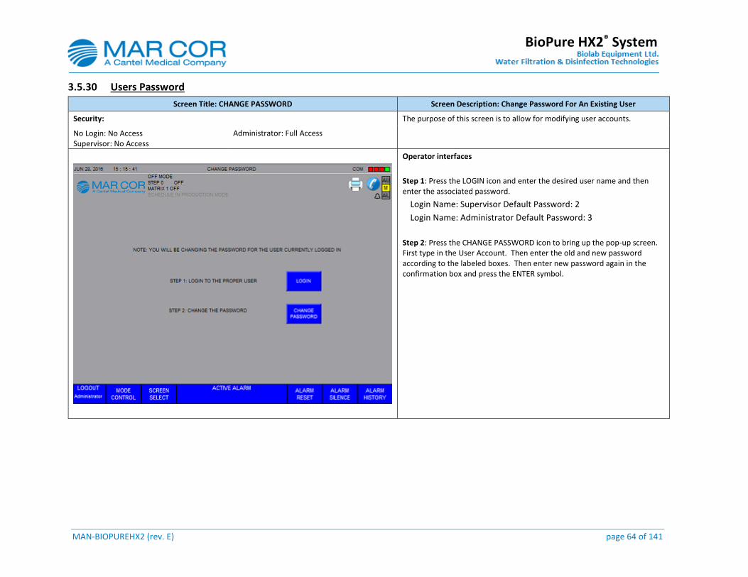
MAN-BIOPUREHX2 (rev. E) page 64 of 141
BioPure HX2® System
3.5.30 Users Password
Screen Title: CHANGE PASSWORD Screen Description: Change Password For An Existing User
Security: The purpose of this screen is to allow for modifying user accounts.
No Login: No Access Supervisor: No Access
Administrator: Full Access
Operator interfaces
Step 1: Press the LOGIN icon and enter the desired user name and then enter the associated password.
Login Name: Supervisor Default Password: 2
Login Name: Administrator Default Password: 3
Step 2: Press the CHANGE PASSWORD icon to bring up the pop-up screen. First type in the User Account. Then enter the old and new password according to the labeled boxes. Then enter new password again in the confirmation box and press the ENTER symbol.

MAN-BIOPUREHX2 (rev. E) page 65 of 141
BioPure HX2® System
3.5.31 Reset User Password
Screen Title: RESET PASSWORD Screen Description: Reset Password For A New User
Security: The purpose of this screen is to allow for resetting password for new user accounts.
No Login: No Access Supervisor: No Access
Administrator: Full Access
0perator interfaces
Step 1: Enter the desired user name in the User Account box.
User Names: Supervisor; Administrator.
Step 2: Enter new password and re-enter to confirm new password entry.
Step 3: Press the CHANGE PASSWORD icon. The RESULT box will report the results of the reset operation as one of the following:
Success.
Internal error, cannot access security component.
Internal error, cannot update MER File with new password.
User %s credentials are incorrect.
%s is replaced with specified user account.
User %s account has been disabled.
%s is replaced with specified user account.
Password cannot exceed %d characters.
%d is read from FactoryTalk Security policy.
"The password cannot be changed.
FactoryTalk Security policy is preventing the operation from succeeding.
Password must be active for over %d days before it can be changed.
%d is read from FactoryTalk Security policy settings.
The password has already been used.
FactoryTalk Security policy is preventing the operation from succeeding.
Password must be at more than %d characters long.
%d is read from FactoryTalk Security policy settings.
Password does not meet complexity requirements.
FactoryTalk Security policy is preventing the operation from succeeding.
Windows-Linked user account password can only be changed in Windows.
Password cannot be changed. Access denied.
FactoryTalk Security is preventing the operation from succeeding.
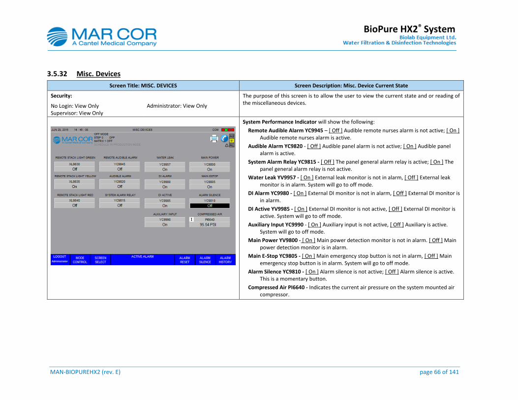
MAN-BIOPUREHX2 (rev. E) page 66 of 141
BioPure HX2® System
3.5.32 Misc. Devices
Screen Title: MISC. DEVICES Screen Description: Misc. Device Current State
Security: The purpose of this screen is to allow the user to view the current state and or reading of the miscellaneous devices.
No Login: View Only Supervisor: View Only
Administrator: View Only
System Performance Indicator will show the following:
Remote Audible Alarm YC9945 – [ Off ] Audible remote nurses alarm is not active; [ On ] Audible remote nurses alarm is active.
Audible Alarm YC9820 - [ Off ] Audible panel alarm is not active; [ On ] Audible panel alarm is active.
System Alarm Relay YC9815 - [ Off ] The panel general alarm relay is active; [ On ] The panel general alarm relay is not active.
Water Leak YV9957 - [ On ] External leak monitor is not in alarm, [ Off ] External leak monitor is in alarm. System will go to off mode.
DI Alarm YC9980 - [ On ] External DI monitor is not in alarm, [ Off ] External DI monitor is in alarm.
DI Active YV9985 - [ On ] External DI monitor is not active, [ Off ] External DI monitor is active. System will go to off mode.
Auxiliary Input YC9990 - [ On ] Auxiliary input is not active, [ Off ] Auxiliary is active. System will go to off mode.
Main Power YV9800 - [ On ] Main power detection monitor is not in alarm. [ Off ] Main power detection monitor is in alarm.
Main E-Stop YC9805 - [ On ] Main emergency stop button is not in alarm, [ Off ] Main emergency stop button is in alarm. System will go to off mode.
Alarm Silence YC9810 - [ On ] Alarm silence is not active; [ Off ] Alarm silence is active. This is a momentary button.
Compressed Air PI6640 - Indicates the current air pressure on the system mounted air compressor.
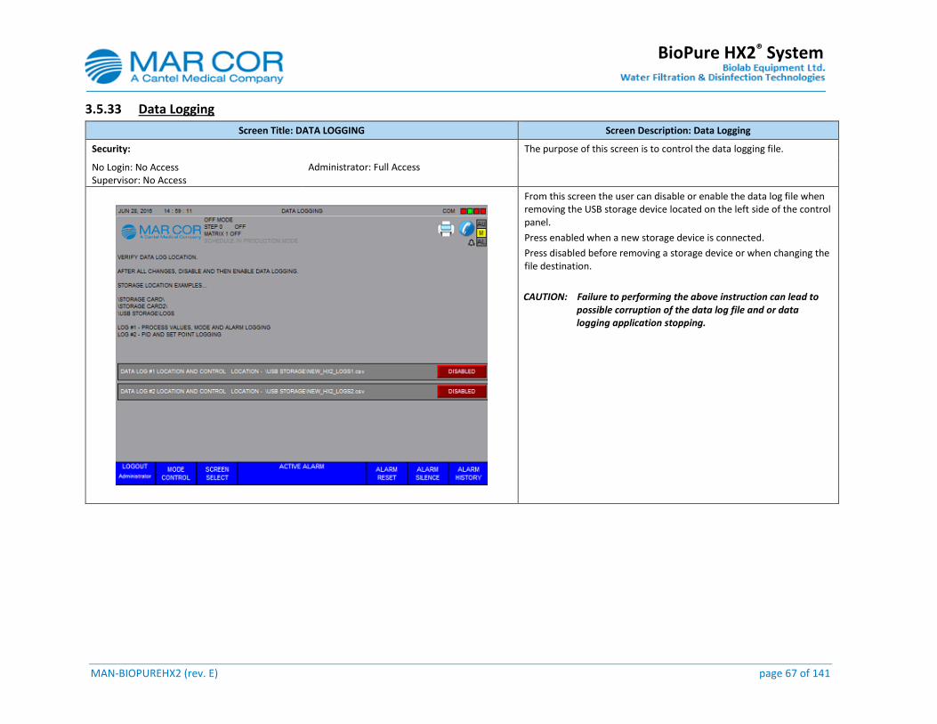
MAN-BIOPUREHX2 (rev. E) page 67 of 141
BioPure HX2® System
3.5.33 Data Logging
Screen Title: DATA LOGGING Screen Description: Data Logging
Security: The purpose of this screen is to control the data logging file.
No Login: No Access Supervisor: No Access
Administrator: Full Access
From this screen the user can disable or enable the data log file when removing the USB storage device located on the left side of the control panel.
Press enabled when a new storage device is connected.
Press disabled before removing a storage device or when changing the file destination.
CAUTION: Failure to performing the above instruction can lead to possible corruption of the data log file and or data logging application stopping.
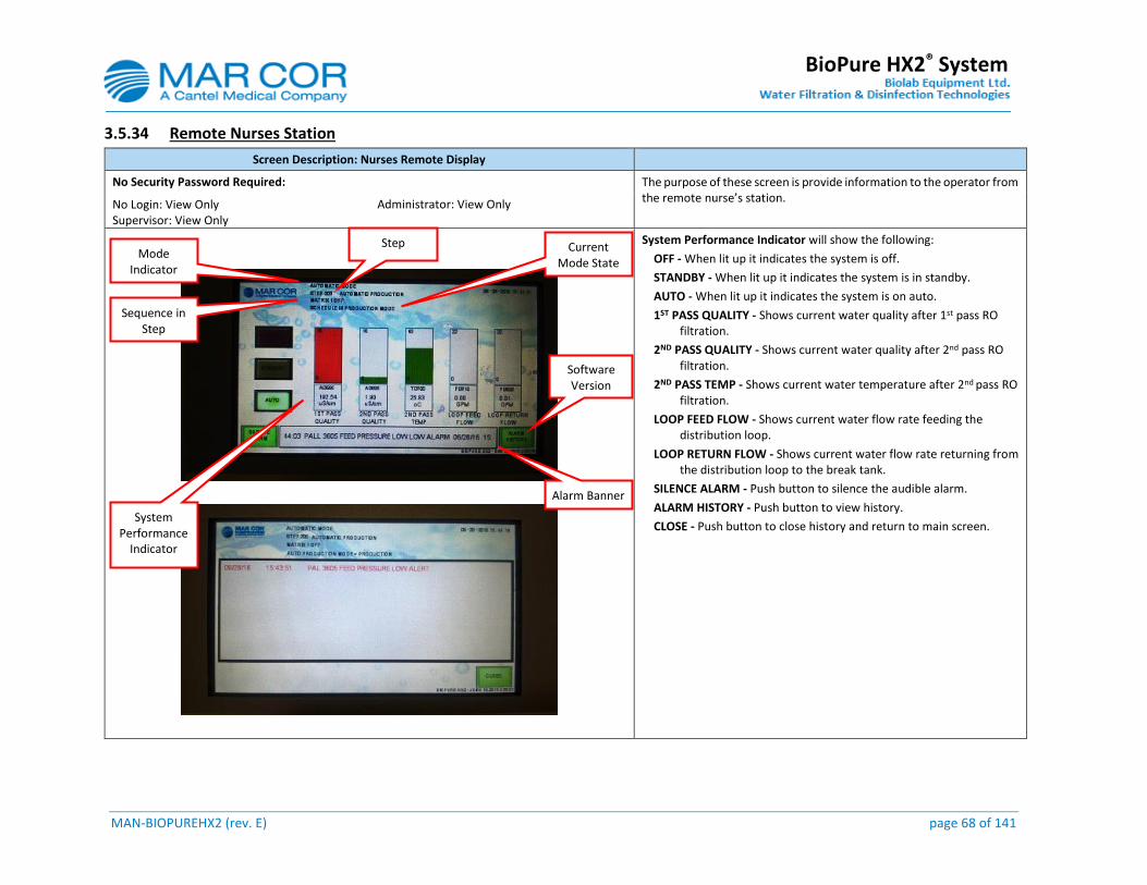
MAN-BIOPUREHX2 (rev. E) page 68 of 141
BioPure HX2® System
3.5.34 Remote Nurses Station
Screen Description: Nurses Remote Display
No Security Password Required: The purpose of these screen is provide information to the operator from the remote nurse’s station.
No Login: View Only Supervisor: View Only
Administrator: View Only
System Performance Indicator will show the following:
OFF - When lit up it indicates the system is off.
STANDBY - When lit up it indicates the system is in standby.
AUTO - When lit up it indicates the system is on auto.
1ST PASS QUALITY - Shows current water quality after 1st pass RO filtration.
2ND PASS QUALITY - Shows current water quality after 2nd pass RO filtration.
2ND PASS TEMP - Shows current water temperature after 2nd pass RO filtration.
LOOP FEED FLOW - Shows current water flow rate feeding the distribution loop.
LOOP RETURN FLOW - Shows current water flow rate returning from the distribution loop to the break tank.
SILENCE ALARM - Push button to silence the audible alarm.
ALARM HISTORY - Push button to view history.
CLOSE - Push button to close history and return to main screen.
System Performance
Indicator
Alarm Banner
Software Version
Mode Indicator
Step
Sequence in Step
Current Mode State
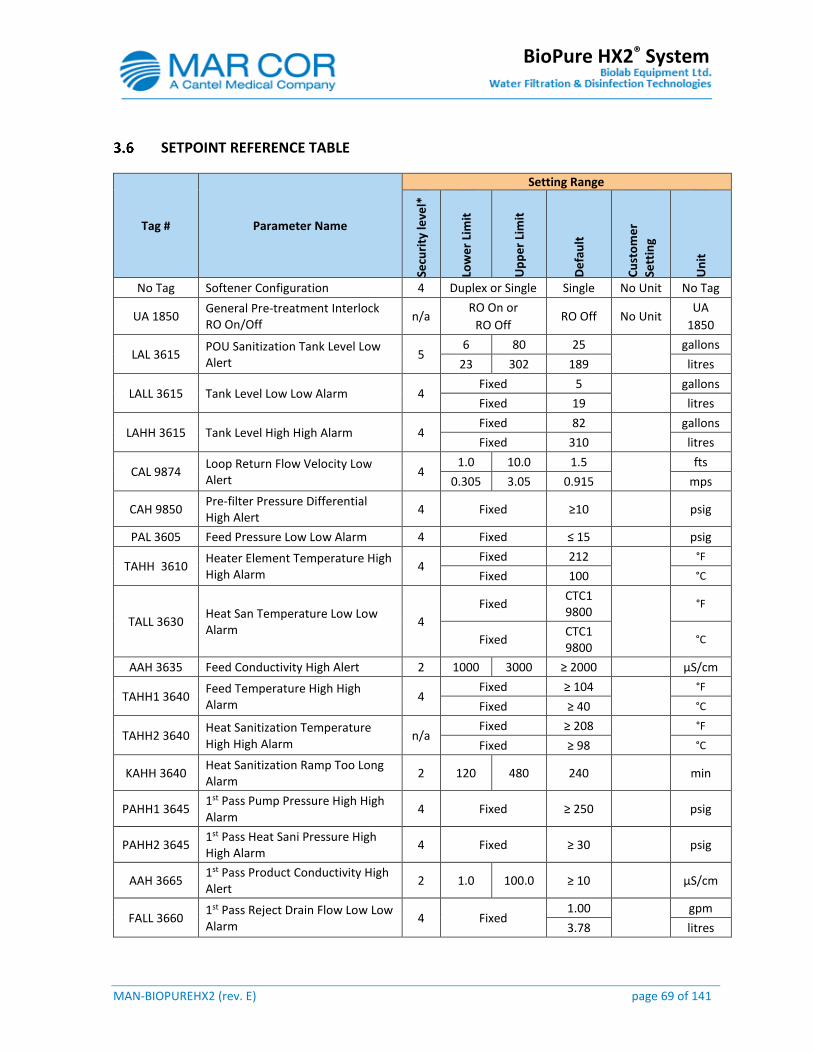
MAN-BIOPUREHX2 (rev. E) page 69 of 141
BioPure HX2® System
SETPOINT REFERENCE TABLE
Tag # Parameter Name
Setting Range
Secu
rity
leve
l*
Low
er
Lim
it
Up
pe
r Li
mit
De
fau
lt
Cu
sto
me
r
Sett
ing
Un
it
No Tag Softener Configuration 4 Duplex or Single Single No Unit No Tag
UA 1850 General Pre-treatment Interlock RO On/Off
n/a RO On or
RO Off RO Off No Unit
UA
1850
LAL 3615 POU Sanitization Tank Level Low Alert
5 6 80 25
gallons
23 302 189 litres
LALL 3615 Tank Level Low Low Alarm 4 Fixed 5
gallons
Fixed 19 litres
LAHH 3615 Tank Level High High Alarm 4 Fixed 82
gallons
Fixed 310 litres
CAL 9874 Loop Return Flow Velocity Low Alert
4 1.0 10.0 1.5
fts
0.305 3.05 0.915 mps
CAH 9850 Pre-filter Pressure Differential High Alert
4 Fixed ≥10 psig
PAL 3605 Feed Pressure Low Low Alarm 4 Fixed ≤ 15 psig
TAHH 3610 Heater Element Temperature High High Alarm
4 Fixed 212
°F
Fixed 100 °C
TALL 3630 Heat San Temperature Low Low Alarm
4
Fixed CTC1 9800
°F
Fixed CTC1 9800
°C
AAH 3635 Feed Conductivity High Alert 2 1000 3000 ≥ 2000 µS/cm
TAHH1 3640 Feed Temperature High High Alarm
4 Fixed ≥ 104
°F
Fixed ≥ 40 °C
TAHH2 3640 Heat Sanitization Temperature High High Alarm
n/a Fixed ≥ 208
°F
Fixed ≥ 98 °C
KAHH 3640 Heat Sanitization Ramp Too Long Alarm
2 120 480 240 min
PAHH1 3645 1st Pass Pump Pressure High High Alarm
4 Fixed ≥ 250 psig
PAHH2 3645 1st Pass Heat Sani Pressure High High Alarm
4 Fixed ≥ 30 psig
AAH 3665 1st Pass Product Conductivity High Alert
2 1.0 100.0 ≥ 10 µS/cm
FALL 3660 1st Pass Reject Drain Flow Low Low Alarm
4 Fixed 1.00
gpm
3.78 litres
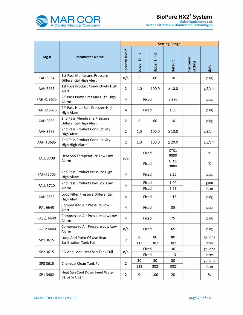
MAN-BIOPUREHX2 (rev. E) page 70 of 141
BioPure HX2® System
Tag # Parameter Name
Setting Range
Secu
rity
leve
l*
Low
er
Lim
it
Up
pe
r Li
mit
De
fau
lt
Cu
sto
me
r
Sett
ing
Un
it
CAH 9854 1st Pass Membrane Pressure Differential High Alert
n/a 5 60 10 psig
AAH 3665 1st Pass Product Conductivity High Alert
2 1.0 100.0 ≥ 10.0 µS/cm
PAHH1 3675 2nd Pass Pump Pressure High High Alarm
4 Fixed ≥ 280 psig
PAHH2 3675 2nd Pass Heat Sani Pressure High High Alarm
4 Fixed ≥ 30 psig
CAH 9856 2nd Pass Membrane Pressure Differential High Alert
2 5 60 10 psig
AAH 3695 2nd Pass Product Conductivity High Alert
2 1.0 100.0 ≥ 10.0 µS/cm
AAHH 3695 2nd Pass Product Conductivity High High Alarm
2 1.0 100.0 ≥ 20.0 µS/cm
TALL 3700 Heat San Temperature Low Low Alarm
n/a
Fixed CTC1 9880
°F
Fixed CTC1 9880
°C
PAHH 3705 2nd Pass Product Pressure High High Alarm
4 Fixed ≥ 95 psig
FALL 3710 2nd Pass Product Flow Low Low Alarm
4 Fixed 1.00
gpm
Fixed 3.78 litres
CAH 9852 Loop Filter Pressure Differential High Alert
4 Fixed ≥ 15 psig
PAL 6640 Compressed Air Pressure Low Alert
4 Fixed 85 psig
PALL1 6440 Compressed Air Pressure Low Low Alarm
4 Fixed 75 psig
PALL2 6440 Compressed Air Pressure Low Low Alarm
n/a Fixed 65 psig
SP1 3615 Loop And Point Of Use Heat Sanitization Tank Full
2 30 80 80
gallons
113 302 302 litres
SP2 3615 RO And Loop Heat San Tank Full n/a Fixed 30
gallons
Fixed 113 litres
SP3 3615 Chemical Clean Tank Full 2 30 80 80
gallons
113 302 302 litres
SP1 3402 Heat San Cool Down Feed Water Valve % Open
2 0 100 20 %
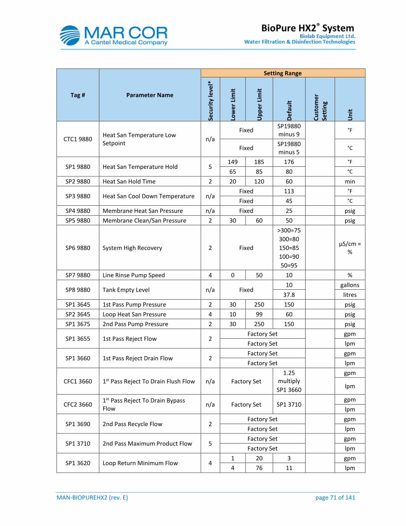
MAN-BIOPUREHX2 (rev. E) page 71 of 141
BioPure HX2® System
Tag # Parameter Name
Setting Range
Secu
rity
leve
l*
Low
er
Lim
it
Up
pe
r Li
mit
De
fau
lt
Cu
sto
me
r
Sett
ing
Un
it
CTC1 9880 Heat San Temperature Low Setpoint
n/a
Fixed SP19880 minus 9
°F
Fixed SP19880 minus 5
°C
SP1 9880 Heat San Temperature Hold 5 149 185 176
°F
65 85 80 °C
SP2 9880 Heat San Hold Time 2 20 120 60 min
SP3 9880 Heat San Cool Down Temperature n/a Fixed 113
°F
Fixed 45 °C
SP4 9880 Membrane Heat San Pressure n/a Fixed 25 psig
SP5 9880 Membrane Clean/San Pressure 2 30 60 50 psig
SP6 9880 System High Recovery 2 Fixed
>300=75
300=80
150=85
100=90
50=95
µS/cm =
%
SP7 9880 Line Rinse Pump Speed 4 0 50 10 %
SP8 9880 Tank Empty Level n/a Fixed 10
gallons
37.8 litres
SP1 3645 1st Pass Pump Pressure 2 30 250 150 psig
SP2 3645 Loop Heat San Pressure 4 10 99 60 psig
SP1 3675 2nd Pass Pump Pressure 2 30 250 150 psig
SP1 3655 1st Pass Reject Flow 2 Factory Set
gpm
Factory Set lpm
SP1 3660 1st Pass Reject Drain Flow 2 Factory Set
gpm
Factory Set lpm
CFC1 3660 1st Pass Reject To Drain Flush Flow n/a Factory Set
1.25 multiply
SP1 3660
gpm
lpm
CFC2 3660 1st Pass Reject To Drain Bypass Flow
n/a Factory Set SP1 3710 gpm
lpm
SP1 3690 2nd Pass Recycle Flow 2 Factory Set
gpm
Factory Set lpm
SP1 3710 2nd Pass Maximum Product Flow 5 Factory Set
gpm
Factory Set lpm
SP1 3620 Loop Return Minimum Flow 4 1 20 3
gpm
4 76 11 lpm
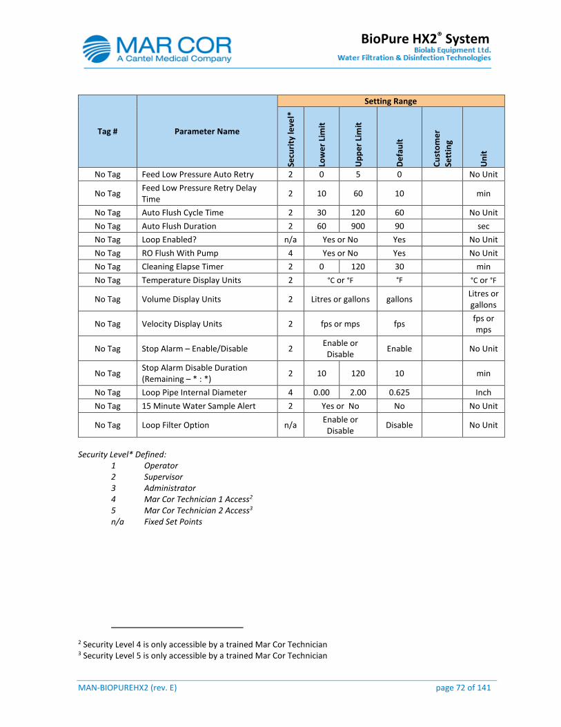
MAN-BIOPUREHX2 (rev. E) page 72 of 141
BioPure HX2® System
Tag # Parameter Name
Setting Range
Secu
rity
leve
l*
Low
er
Lim
it
Up
pe
r Li
mit
De
fau
lt
Cu
sto
me
r
Sett
ing
Un
it
No Tag Feed Low Pressure Auto Retry 2 0 5 0 No Unit
No Tag Feed Low Pressure Retry Delay Time
2 10 60 10 min
No Tag Auto Flush Cycle Time 2 30 120 60 No Unit
No Tag Auto Flush Duration 2 60 900 90 sec
No Tag Loop Enabled? n/a Yes or No Yes No Unit
No Tag RO Flush With Pump 4 Yes or No Yes No Unit
No Tag Cleaning Elapse Timer 2 0 120 30 min
No Tag Temperature Display Units 2 °C or °F °F °C or °F
No Tag Volume Display Units 2 Litres or gallons gallons Litres or gallons
No Tag Velocity Display Units 2 fps or mps fps fps or mps
No Tag Stop Alarm – Enable/Disable 2 Enable or Disable
Enable No Unit
No Tag Stop Alarm Disable Duration (Remaining – * : *)
2 10 120 10 min
No Tag Loop Pipe Internal Diameter 4 0.00 2.00 0.625 Inch
No Tag 15 Minute Water Sample Alert 2 Yes or No No No Unit
No Tag Loop Filter Option n/a Enable or Disable
Disable No Unit
Security Level* Defined:
1 Operator 2 Supervisor 3 Administrator 4 Mar Cor Technician 1 Access2 5 Mar Cor Technician 2 Access3 n/a Fixed Set Points
2 Security Level 4 is only accessible by a trained Mar Cor Technician 3 Security Level 5 is only accessible by a trained Mar Cor Technician
MAN-BIOPUREHX2 (rev. E) page 73 of 141
BioPure HX2® System
4.0 SYSTEM OPERATION
SYSTEM VERIFICATION BEFORE STARTING UP
Prior to starting the BioPure HX2® system, verify the following is complete. Once the system has been flooded with pretreated water it must be placed into operation within a day.
1. Temperature blending valve is installed, flushed and temperature is set to 77°F (25°C). 2. Softener(s) are installed, programmed, flushed and outlet water hardness tested. 3. A minimum of two carbon filters are installed in series, programmed (if automatic), flushed
and outlet water tested for chlorine. 4. Pressure regulator after the last pre-treatment step is installed and set to between 16 and
30 psig. 5. Pre-treatment electrical interlocks are installed and verified. 6. Electrical supply is connected and power is adequate to support the RO system. 7. Interconnect and loop piping including drains are complete and verified. 8. All system pipelines are pressure tested for leaks and flushed to remove debris. 9. RO pre-filter cartridges and/or optional loop filter cartridges are installed. 10. All other accessories are installed and ready to receive water.
NOTE: Other pre-treatment devices (Media filter, Chemical Injection, Iron Filter……) may be required depending on the potable feed water analysis. Please consult with a Mar Cor sales representative.
PANEL START-UP AND SHUT DOWN
The panel is equipped with a 120VAC uninterruptable power supply (UPS) located in the upper control cabinet. It will provide approximately 20 minutes of control power to the system. You must turn off the main power and UPS to remove power from the system.
4.2.1 Panel Start-up
1. Open the top control panel and press and hold the UPS power button for 3 seconds to turn it on. The UPS is located in the top left hand corner.
2. Turn the main power disconnect to the ON position. It is located on the top right hand corner of the lower panel.
3. Close the top panel and secure door. 4. Allow the panel to initialize for 5 minutes.
4.2.2 Panel Shut Down
1. Turn the main power disconnect to the OFF position. It is located on the top right hand corner of the lower panel.
2. Open the top control panel and press and hold the UPS power button for 3 seconds to turn it off. The UPS is located in the top left hand corner.

MAN-BIOPUREHX2 (rev. E) page 74 of 141
BioPure HX2® System
WARNING: Uninterruptible power supply located inside control panel. Main disconnect does not de-energize all circuits.
WARNING: Use proper safety procedures when working in the electrical panel. Disconnect and/or lock-out the power supply to the system and tag it out. The system must be properly grounded to prevent personal injury or damage to the system.
MANUAL START-UP / SHUT DOWN PROCEDURE
After the system has been placed in operation for the 1st time it will not require any user input to operate normally with the condition that the system is controlled based on the scheduled time programmed in the calendar. If desired the nurse / operator (no password) can start the system when required and place the system in standby at the end of the day:
1. From the SCHEDULE screen (security level Supervisor or higher), disable the production schedule for each day.
2. From the MAIN screen press the AUTO icon to place the system into production when required.
3. From the MAIN screen press the STANDBY icon to place the system into standby when required. Placing the system in standby will allow the scheduled heat sanitization to initiate as programmed.
WARNING: Do not place the system in OFF unless maintenance is required for facility issues. Placing the system if OFF mode for more than 24 hours can result in excessive bacterial growth. Should this occur; a full system heat sanitization and water quality sampling must be performed prior to use.
NOTE: When the system is in full production (Mode #8) and a power failure should occur the system will attempt to perform a rapid recovery but only if the main power to the panel is restored in less than 5 minutes. If the power is restored the system will restart in Mode #8 in less than 5 seconds and ramp up to the last production flow rate in less than 15 seconds. If the power is restored after 5 minutes the system will perform the normal start-up flushes to assure the water and microbiological quality is met.
HEAT SANITIZATION
Heat sanitization can be initiated manually by the user at any time in Standby or automatically based on the system scheduler when in Standby, or in Automatic Mode, during Sleep.
The system scheduler will allow the user to select what part of the system to sanitize, the day and hour to initiate a sanitization, typically in the off hours or weekends.

MAN-BIOPUREHX2 (rev. E) page 75 of 141
BioPure HX2® System
The sequence is password protected requiring a security level Supervisor or higher. The scheduler will allow a single heat sanitization cycle per day, and can be one of the following choices:
Heat Sanitization Selection Type Approximate Duration
1st Pass Manual or Auto ≈ 4 hrs
2nd Pass Manual or Auto ≈ 4 hrs
Loop Manual or Auto ≈ 4 hrs
Loop And Points of Use Manual User Aborted or Programmable Timer
1st Pass → 2nd Pass Manual or Auto ≈ 8 hrs
2nd Pass → Loop Manual or Auto ≈ 8 hrs
1st Pass → 2nd Pass → Loop Manual or Auto ≈ 12 hrs
NOTE: Duration time will vary depending on loop length, hold temperature, hold time, ambient temperature, insulation type and site installation. Times indicated above include a hold temperature of 80°C (176°F), hold time of 60 minutes and loop length of 305 meters (1,000 ft.) partially insulated.
The typical RO membrane sanitization frequency is once a month to a maximum of once a week. A loop sanitization can be performed on a daily basis. If more frequent sanitizations are required it will affect the normal life span or calibration frequency of critical components on the system.
The schedulers within the system are monitored by the PLC. The PLC will close a digital output to delay the regeneration and/or backwash initiation sequence of the pre-treatment (if equipped) during heat sanitization modes. Once the sanitization is completed the PLC will open the digital output.
During a heat sanitization the horn will sound every 15 seconds for 0.5 seconds. Every 10 minutes the following message will appear on the HMI and recorded in the history.
XXXXX Heat Sanitization In Progress. Temperature XX.X °C
Once a heat sanitization is complete the following message will appear on the HMI and recorded in the history.
XXXXX Heat Sanitization Completed. XXX Minutes at XX.X °C
Started HH:MM:SS YYYY/MM/DD Completed HH:MM:SS YYYY/MM/DD
If for some reason the sanitization should abort the following message will appear on the HMI and recorded in the history.
XXXXX Heat Sanitization Aborted. Started HH:MM:SS YYYY/MM/DD
MAN-BIOPUREHX2 (rev. E) page 76 of 141
BioPure HX2® System
Aborted HH:MM:SS YYYY/MM/DD
WARNING: During the heat sanitization process the water temperature can reach 98°C (208°F). Extreme caution must be taken when handling components on the system.
WARNING: Verify the loop material maximum operating pressure versus temperature. Set the heat sanitization pump speed at least 10 % below that pressure. Possible hot water leaks and or flooding can occur if operating above the loop material specifications.
4.4.1 Auto Heat Sanitization
An auto heat sanitization can be scheduled during non-usage periods. It is important to leave enough time for the heat sanitization to complete. If pre-treatment devices used have a regeneration or backwash schedule, ensure they do not conflict with the auto heat sanitization schedule unless they are equipped with a lock-out input connected to the panel. An auto heat sanitization will only occur if the system is in Standby or Auto (Sleep).
Refer to section 3.5.29 for instructions on how to set the time schedule for auto heat sanitizations.
4.4.2 Manual Heat Sanitization
A manual heat sanitization can be scheduled during non-usage periods. It is important to leave enough time for the heat sanitization to complete. If pre-treatment devices used have a regeneration or backwash schedule, ensure they do not conflict with the auto heat sanitization schedule unless they are equipped with a lock-out input connected to the panel.
1. From the Mode Control screen, log in with username and password. 2. Press the Standby mode icon if the system is operating. 3. Press the desired heat sani icon in the single heat sanitization headline and allow the
system to complete its cycle. The sequence of heat sani process is displayed in the Status screen for monitoring purpose.
4. Once sani is complete the system will return to STANDBY mode.
The heat sanitization is logged in the HMI as complete.
4.4.3 Loop and Points of use Heat Sanitization
A manual heat sanitization of the loop and points of use can be scheduled during non- usage periods. It is important to leave enough time for the heat sanitization to complete. If pre-treatment devices used have a regeneration or backwash schedule, ensure they do not conflict with the auto heat sanitization schedule unless they are equipped with a lock-out input connected to the panel.
1. From the Mode Control screen, log in with username and password. 2. Press the Standby Mode icon if the system is normally operating. 3. Press the Loop & POU icon under the heading for single heat sanitization and allow the
system water temperature to ramp to the set temperature.
MAN-BIOPUREHX2 (rev. E) page 77 of 141
BioPure HX2® System
4. Once the temperature is reached the PLC will provide an HMI indication that the temperature is reached and hot water can be drawn from the points of use.
The system will maintain the temperature and display the tank level in real time throughout the hold period.
An alert on the HMI and horn will activate once the tank reaches the adjustable low level setpoint.
At the beginning of the mode an adjustable counter will start. Should the counter reach zero before any other alarm, the sanitization sequence will abort and begin a cool down sequence.
5. If the user does not press Sanitization Complete button and the Break Tank level reaches the low low level alarm, the 1st pass RO pump will stop along with the heater.
6. Once the low level alert setpoint is reached the operator shall close all the points of use and press the Sanitization Complete icon. The system will transition to the cool down sequence and the heat sanitization is logged in the HMI as complete.
7. Once the cool down sequence is complete the system will return to Standby mode. 8. The sequence of heat sani process is displayed in the Status screen for monitoring
purpose.
EMERGENCY BY-PASS OPERATION
In an emergency situation the system can be operated in either first pass by-pass or second pass by-pass. When placed in either mode the 2nd pass quality alert setpoint will automatically change to 10 µS/cm and the 2nd pass quality divert setpoint will automatically change to 20 µS/cm. The reason for this is because in by-pass mode the system operates as a single pass RO producing lower quality water.
NOTE: An optional by-pass circuit can be added to the panel to allow for manual operation of the system if for some reason the PLC or HMI should fail.
4.5.1 1st Pass By-Pass Operation
1. Determine and record the issue. 2. Place the system in OFF mode from the Mode Control screen. 3. Close valve V3230 on the inlet to the 1st pass pump P3015. 4. Log in with username and password. 5. Press the Maintenance Mode icon and then press the 1st Pass Bypass icon. 6. Press the Screen Select icon. 7. Press the Status icon. 8. Read the Message and then press the Next icon. The system will automatically restart
and operate at a programmed product flow rate. The recovery is automatically adjusted to 50%.
9. Contact Mar Cor service with the issue to arrange a service call.
NOTE: No heat sanitization can be performed when in emergency by-pass operation.
MAN-BIOPUREHX2 (rev. E) page 78 of 141
BioPure HX2® System
CAUTION: The system should only operate in either by-pass modes for no more than a week.
WARNING: The system must be shut down when performing service work on the system in by-pass operation.
4.5.2 2nd Pass By-Pass Operation
1. Determine and record the issue. 2. Place the system in OFF mode from the Mode Control screen. 3. Close valve V3260 on the inlet to the 2nd pass pump P3025. 4. Log in with username and password. 5. Press the Maintenance Mode icon and then press the 2nd Pass Bypass icon. The system
will automatically restart and operate at a programmed product flow rate. The recovery is automatically adjusted to 50%.
6. Press the Screen Select icon. 7. Press the Status icon. 8. Read the Message and then press the Next icon. The system will automatically restart
and operate at a programmed product flow rate. The recovery is automatically adjusted to 50%.
9. Contact Mar Cor service with the issue to arrange a service call.
NOTE: No heat sanitization can be performed when in emergency by-pass operation.
CAUTION: The system should only operate in either by-pass modes for no more than a week.
WARNING: The system must be shut down when performing service work on the system in by-pass operation.
4.5.3 Manual By-pass Operation
If the PLC and or HMI should fail the system can be place into manual operation.
1. Push the emergency stop red button on front of panel and wait for 10 seconds then reset the emergency stop push button.
2. Open the top control panel and locate the manual by pass key switch. With the key installed turn the switch to manual. The following will occur.
Feed water valve YV3430 will open and 1st pass pump P3015 will start and ramp to the pre-set speed programmed in the variable speed drive.
After a time delay the 2nd pass pump P3025 will start and ramp to the pre-set speed programmed in the variable speed drive.
Once the conductivity quality setpoint (10µS/cm) is met on the second pass product outlet AE3695 the 2nd pass product divert valve YV3470 will divert to the loop feed. The conductivity setpoint is programmed in the quality meter AIT9600 located inside the top control panel.
3. Monitor feed water pressure and pre-treatment devices during this time to prevent running the pump without water.
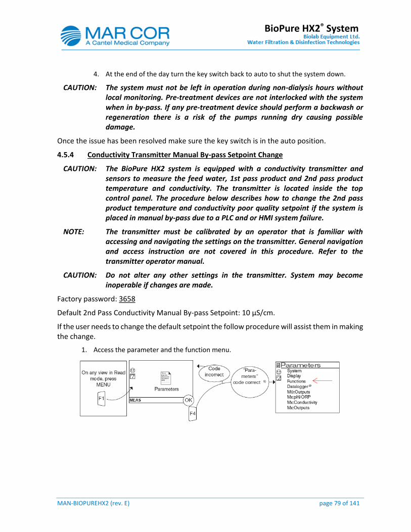
MAN-BIOPUREHX2 (rev. E) page 79 of 141
BioPure HX2® System
4. At the end of the day turn the key switch back to auto to shut the system down.
CAUTION: The system must not be left in operation during non-dialysis hours without local monitoring. Pre-treatment devices are not interlocked with the system when in by-pass. If any pre-treatment device should perform a backwash or regeneration there is a risk of the pumps running dry causing possible damage.
Once the issue has been resolved make sure the key switch is in the auto position.
4.5.4 Conductivity Transmitter Manual By-pass Setpoint Change
CAUTION: The BioPure HX2 system is equipped with a conductivity transmitter and sensors to measure the feed water, 1st pass product and 2nd pass product temperature and conductivity. The transmitter is located inside the top control panel. The procedure below describes how to change the 2nd pass product temperature and conductivity poor quality setpoint if the system is placed in manual by-pass due to a PLC and or HMI system failure.
NOTE: The transmitter must be calibrated by an operator that is familiar with accessing and navigating the settings on the transmitter. General navigation and access instruction are not covered in this procedure. Refer to the transmitter operator manual.
CAUTION: Do not alter any other settings in the transmitter. System may become inoperable if changes are made.
Factory password: 3658
Default 2nd Pass Conductivity Manual By-pass Setpoint: 10 µS/cm.
If the user needs to change the default setpoint the follow procedure will assist them in making the change.
1. Access the parameter and the function menu.
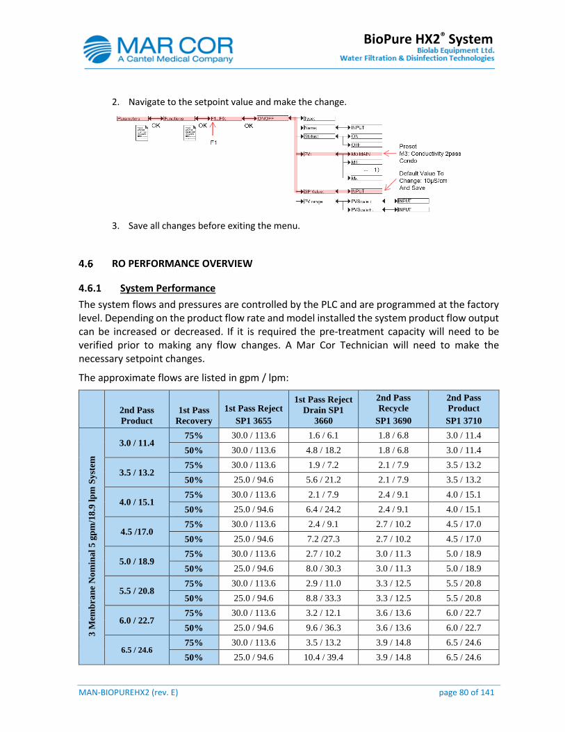
MAN-BIOPUREHX2 (rev. E) page 80 of 141
BioPure HX2® System
2. Navigate to the setpoint value and make the change.
3. Save all changes before exiting the menu.
RO PERFORMANCE OVERVIEW
4.6.1 System Performance
The system flows and pressures are controlled by the PLC and are programmed at the factory level. Depending on the product flow rate and model installed the system product flow output can be increased or decreased. If it is required the pre-treatment capacity will need to be verified prior to making any flow changes. A Mar Cor Technician will need to make the necessary setpoint changes.
The approximate flows are listed in gpm / lpm:
2nd Pass
Product
1st Pass
Recovery
1st Pass Reject
SP1 3655
1st Pass Reject
Drain SP1
3660
2nd Pass
Recycle
SP1 3690
2nd Pass
Product
SP1 3710
3 M
emb
ran
e N
om
ina
l 5
gp
m/1
8.9
lp
m S
yst
em
3.0 / 11.4 75% 30.0 / 113.6 1.6 / 6.1 1.8 / 6.8 3.0 / 11.4
50% 30.0 / 113.6 4.8 / 18.2 1.8 / 6.8 3.0 / 11.4
3.5 / 13.2 75% 30.0 / 113.6 1.9 / 7.2 2.1 / 7.9 3.5 / 13.2
50% 25.0 / 94.6 5.6 / 21.2 2.1 / 7.9 3.5 / 13.2
4.0 / 15.1 75% 30.0 / 113.6 2.1 / 7.9 2.4 / 9.1 4.0 / 15.1
50% 25.0 / 94.6 6.4 / 24.2 2.4 / 9.1 4.0 / 15.1
4.5 /17.0 75% 30.0 / 113.6 2.4 / 9.1 2.7 / 10.2 4.5 / 17.0
50% 25.0 / 94.6 7.2 /27.3 2.7 / 10.2 4.5 / 17.0
5.0 / 18.9 75% 30.0 / 113.6 2.7 / 10.2 3.0 / 11.3 5.0 / 18.9
50% 25.0 / 94.6 8.0 / 30.3 3.0 / 11.3 5.0 / 18.9
5.5 / 20.8 75% 30.0 / 113.6 2.9 / 11.0 3.3 / 12.5 5.5 / 20.8
50% 25.0 / 94.6 8.8 / 33.3 3.3 / 12.5 5.5 / 20.8
6.0 / 22.7 75% 30.0 / 113.6 3.2 / 12.1 3.6 / 13.6 6.0 / 22.7
50% 25.0 / 94.6 9.6 / 36.3 3.6 / 13.6 6.0 / 22.7
6.5 / 24.6 75% 30.0 / 113.6 3.5 / 13.2 3.9 / 14.8 6.5 / 24.6
50% 25.0 / 94.6 10.4 / 39.4 3.9 / 14.8 6.5 / 24.6

MAN-BIOPUREHX2 (rev. E) page 81 of 141
BioPure HX2® System
7.0 / 26.5 75% 30.0 / 113.6 3.3 / 12.5 3.0 / 11.4 7.0 / 26.5
50% 25.0 / 94.6 10.0 / 37.9 3.0 / 11.4 7.0 / 26.5
2nd Pass
Product
1st Pass
Recovery
1st Pass Reject
SP1 3655
1st Pass Reject
Drain SP1
3660
2nd Pass
Recycle
SP1 3690
2nd Pass
Product
SP1 3710
6 M
emb
ran
e N
om
ina
l 1
1 g
pm
/14
.6 l
pm
Sy
stem
7.0 / 26.5 75% 30.0 / 113.6 3.7 / 14.0 3.0 / 11.4 7.0 / 26.5
50% 20.0 / 75.7 11.2 / 42.4 3.0 / 11.4 7.0 / 26.5
7.5 / 28.4 75% 30.0 / 113.6 4.0 / 15.1 4.5 / 17.0 7.5 / 28.4
50% 20.0 / 75.7 12.0 / 45.4 4.5 / 17.0 7.5 / 28.4
8.0 / 30.3 75% 30.0 / 113.6 4.3 / 16.3 4.8 / 18.2 8.0 / 30.3
50% 20.0 / 75.7 12.8 / 48.5 4.8 /18.2 8.0 / 30.3
8.5 / 32.2 75% 30.0 / 113.6 4.5 / 17.0 5.1 / 19.3 8.5 / 32.2
50% 20.0 / 75.7 13.6 / 51.5 5.1 / 19.3 8.5 / 32.2
9.0 / 34.1 75% 30.0 / 113.6 4.8 / 18.2 5.4 / 20.4 9.0 / 34.1
50% 20.0 / 75.7 14.4 / 54.5 5.4 / 20.4 9.0 / 34.1
9.5 / 35.9 75% 30.0 / 113.6 5.1 / 19.3 5.7 / 21.6 9.5 / 35.9
50% 15.0 / 56.7 15.2 / 57.5 5.7 / 21.6 9.5 / 35.9
10.0 / 37.9 75% 25.0 / 94.6 5.3 / 20.1 6.0 / 22.7 10.0 / 37.9
50% 15.0 / 56.7 16.0 / 60.6 6.0 / 22.7 10.0 / 37.9
10.5 / 39.7 75% 25.0 / 94.6 5.6 / 21.2 6.3 / 23.8 10.5 / 39.7
50% 15.0 / 56.7 16.8 / 63.6 6.3 / 23.8 10.5 / 39.7
11.0 / 41.6 75% 25.0 / 94.6 5.9 / 22.3 6.6 / 25.0 11.0 / 41.6
50% 15.0 / 56.7 17.6 / 66.6 6.6 / 25.0 11.0 / 41.6
11.5 / 43.5 75% 25.0 / 94.6 6.1 / 23.1 6.9 / 26.1 11.5 / 43.5
50% 15.0 / 56.7 18.4 / 69.7 6.9 / 26.1 11.5 / 43.5
12.0 / 45.4 75% 25.0 / 94.6 6.4 / 24.2 7.2 / 27.3 12.0 / 45.4
50% 15.0 / 56.7 19.1 / 72.3 7.2 / 27.3 12.0 / 45.4
12.5 / 47.3 75% 25.0 / 94.6 6.7 / 25.4 7.5 / 28.4 12.5 / 47.3
50% 15.0 / 56.7 20.0 / 75.7 7.5 / 28.4 12.5 / 47.3
13.0 / 49.2 75% 25.0 / 94.6 6.2 / 23.5 5.6 / 21.2 13.0 / 49.2
50% 15.0 / 56.7 18.6 / 70.4 5.6 / 21.2 13.0 / 49.2
13.5 / 51.1 75% 25.0 / 94.6 6.4 / 24.2 5.8 / 22.0 13.5 / 51.1
50% 15.0 / 56.7 19.3 / 73.1 5.8 / 22.0 13.5 / 51.1
14.0 / 53.0 75% 25.0 / 94.6 6.7 / 25.4 6.0 / 22.7 14.0 / 53.0
50% 10.0 / 37.9 20.0 / 75.7 6.0 / 22.7 14.0 / 53.0
14.5 / 54.9 75% 25.0 / 94.6 6.4 / 24.2 4.8 / 18.2 14.5 / 54.9
50% 15.0 / 56.7 19.3 / 73.1 4.8 / 18.2 14.5 / 54.9
15.0 / 56.8 75% 25.0 / 94.6 6.7 / 25.4 5.0 / 18.9 15.0 / 56.8
50% 30.0 / 113.6 3.7 / 14.0 3.0 / 11.4 7.0 / 26.5
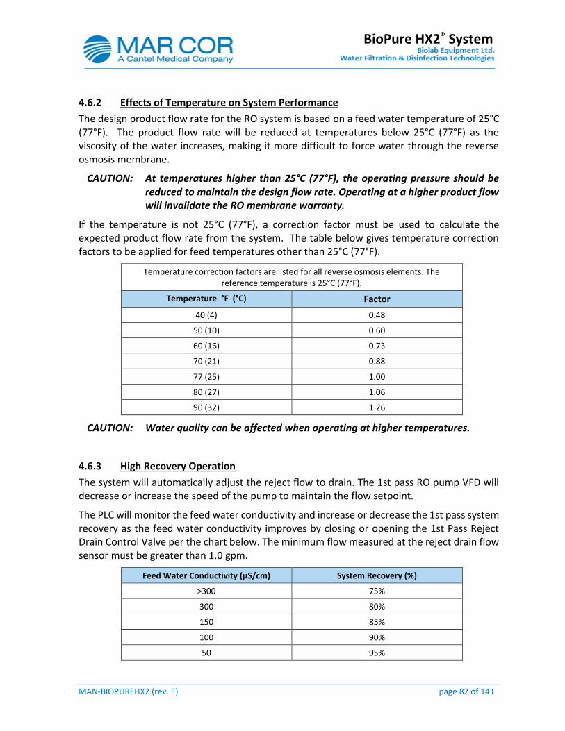
MAN-BIOPUREHX2 (rev. E) page 82 of 141
BioPure HX2® System
4.6.2 Effects of Temperature on System Performance
The design product flow rate for the RO system is based on a feed water temperature of 25°C (77°F). The product flow rate will be reduced at temperatures below 25°C (77°F) as the viscosity of the water increases, making it more difficult to force water through the reverse osmosis membrane.
CAUTION: At temperatures higher than 25°C (77°F), the operating pressure should be reduced to maintain the design flow rate. Operating at a higher product flow will invalidate the RO membrane warranty.
If the temperature is not 25°C (77°F), a correction factor must be used to calculate the expected product flow rate from the system. The table below gives temperature correction factors to be applied for feed temperatures other than 25°C (77°F).
Temperature correction factors are listed for all reverse osmosis elements. The reference temperature is 25°C (77°F).
Temperature °F (°C) Factor
40 (4) 0.48
50 (10) 0.60
60 (16) 0.73
70 (21) 0.88
77 (25) 1.00
80 (27) 1.06
90 (32) 1.26
CAUTION: Water quality can be affected when operating at higher temperatures.
4.6.3 High Recovery Operation
The system will automatically adjust the reject flow to drain. The 1st pass RO pump VFD will decrease or increase the speed of the pump to maintain the flow setpoint.
The PLC will monitor the feed water conductivity and increase or decrease the 1st pass system recovery as the feed water conductivity improves by closing or opening the 1st Pass Reject Drain Control Valve per the chart below. The minimum flow measured at the reject drain flow sensor must be greater than 1.0 gpm.
Feed Water Conductivity (µS/cm) System Recovery (%)
>300 75%
300 80%
150 85%
100 90%
50 95%

MAN-BIOPUREHX2 (rev. E) page 83 of 141
BioPure HX2® System
NOTE: If the system is set to operate at 50% recovery the high recovery operation is disabled.
MAN-BIOPUREHX2 (rev. E) page 84 of 141
BioPure HX2® System
5.0 MAINTENANCE
MAINTENANCE REQUIREMENTS
After the BioPure HX2® system has been commissioned; it will require scheduled maintenance at a defined frequency. Regular maintenance is necessary in order to ensure:
The product water quality meets or exceeds the ISO 13959-11 water quality for hæmodialysis applications.
Efficiency of RO performance.
Maximum membrane life.
Section 5.1.3 (log sheet) lists the operating data that needs to be monitored and recorded on the RO system at a specified frequency. Alerts and Alarms are automatically recorded in the PLC history to provide indication when maintenance is required.
All readings and samples must be taken when the system is in normal operation (RO Run To Loop).
Section 5.1.4 includes a list of the recommend service schedule of the system.
A 15 minute water sample alert can be activated on the HMI to provide an audible alert to the nurse / technicians that readings and water samples can be taken. The timer will begin to count once the system has transition to RO Run To Loop mode.
An alarm / alert log in section 5.1.5 is provided to record any alarms / alerts that could occur during maintenance.
All alarms / alerts / messages are recorded in the history on the HMI.
CAUTION: Any changes in feed water chemistry must be dealt with immediately to prevent system poor performance and or system failure.
CAUTION: The log sheet does not cover any parameters that need to be monitored on the pre-treatment or post treatment of the system. Please consult with you Mar Cor representative.
NOTE: Maintenance of the BioPure HX2® system following its installation is the responsibility of the end users to ensure that product water is tested periodically. Appropriate hot water sanitization at scheduled frequency and/or use of chemical sanitization must be performed to maintain acceptable product water quality.
NOTE: Use this system only with the specified feed water and pre-treatment chemicals determined by a Mar Cor representative. Use all sanitizing and cleaning agents according to the instructions in this Manual.
MAN-BIOPUREHX2 (rev. E) page 85 of 141
BioPure HX2® System
5.1.1 RO System Shutdown Procedure
If the RO system is not being used for less than one week, it is usually sufficient to rely on the Auto Flush feature for flushing the system automatically at a pre-set time interval to minimize biological growth. Place the system in Standby to allow the system to perform its auto flush sequence.
If the RO system is not being used for more than one week, it is recommend that the heat sanitization schedule be programmed to perform a heat cycle at a minimum of once a week along with its normal Auto Flush cycles. Place the system in Standby to allow the system to perform its scheduled heat cycles and flush sequences.
If the system must be shut down for an extended time (greater than one week) without water and or power, a preservative solution (1% Sodium Bisulfate) should be added to the system to reduce biological growth. The solution will have to be pumped through the system manually and must be performed by a Mar Cor representative. Membranes shall be flushed with pre-treated water and re-preserved every three months.
WARNING: Placing the system in ‘Off’ mode for greater than 24 hours can result in excessive bacterial growth. A full system heat sanitization and water quality sampling must be performed prior to use.
5.1.2 RO Pre-filter Cartridge Replacement Procedure
NOTE: As with any water system, water spillage on the ground or on the equipment when servicing the equipment is expected. Make sure proper equipment in on hand to dry up excess water during maintenance.
1. Press the Mode Control icon followed by the Off Mode icon. 2. Fully close manual valve (customer installed) to isolate feed water supply. 3. Open vent valve V3210 to depressurize filter chamber. 4. Open sample valve V3205 to drain off water in the housing. 5. Close valve V3205. 6. Unlock the V-clamp to remove filter top cover. 7. Remove the hold-down plate after turning the knob loose. The knob keeps the plate
firmly against the filter cartridges. 8. Remove and discard old filter cartridges. 9. Inspect and replace o-ring if signs of cracking or degrading are found on the housing. 10. Wear clean gloves and install new filter cartridges. 11. Return the hold-down plate and make sure it is set flat on the cartridges. 12. Reinstall knob to keep hold-down plate firmly against the cartridges. 13. Install filter housing top cover and V-clamp. 14. Slowly open the manual feed water valve (customer installed). 15. Once a steady stream of water is seen exiting the vent valve V3210, close the valve. 16. Check for leaks and repair if any are found.
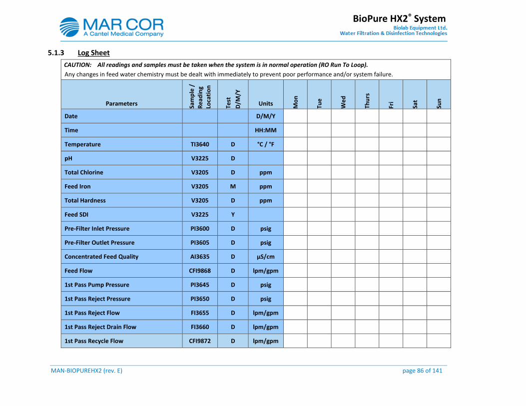
MAN-BIOPUREHX2 (rev. E) page 86 of 141
BioPure HX2® System
5.1.3 Log Sheet
CAUTION: All readings and samples must be taken when the system is in normal operation (RO Run To Loop).
Any changes in feed water chemistry must be dealt with immediately to prevent poor performance and/or system failure.
Parameters Sam
ple
/
Re
adin
g Lo
cati
on
Test
D/M
/Y
Units Mo
n
Tue
We
d
Thu
rs
Fri
Sat
Sun
Date D/M/Y
Time HH:MM
Temperature TI3640 D °C / °F
pH V3225 D
Total Chlorine V3205 D ppm
Feed Iron V3205 M ppm
Total Hardness V3205 D ppm
Feed SDI V3225 Y
Pre-Filter Inlet Pressure PI3600 D psig
Pre-Filter Outlet Pressure PI3605 D psig
Concentrated Feed Quality AI3635 D µS/cm
Feed Flow CFI9868 D lpm/gpm
1st Pass Pump Pressure PI3645 D psig
1st Pass Reject Pressure PI3650 D psig
1st Pass Reject Flow FI3655 D lpm/gpm
1st Pass Reject Drain Flow FI3660 D lpm/gpm
1st Pass Recycle Flow CFI9872 D lpm/gpm
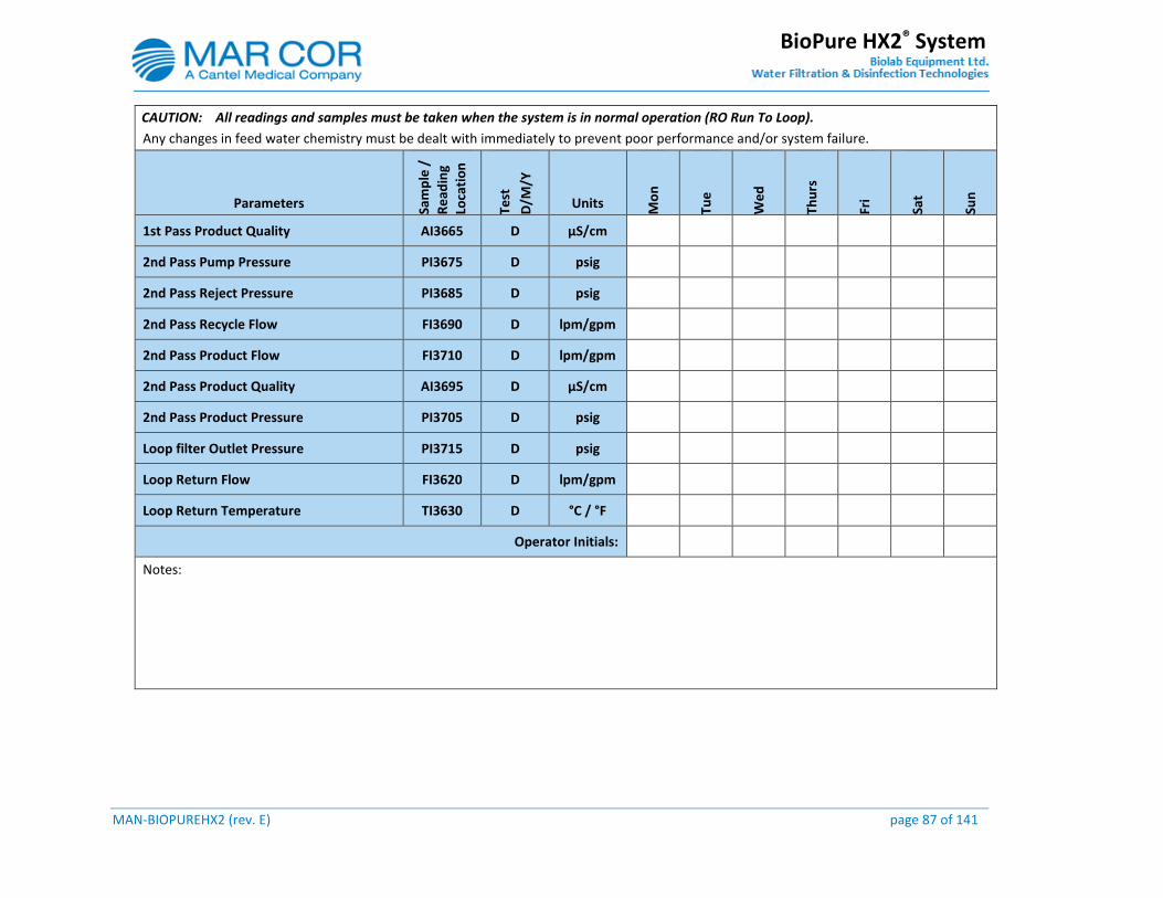
MAN-BIOPUREHX2 (rev. E) page 87 of 141
BioPure HX2® System
CAUTION: All readings and samples must be taken when the system is in normal operation (RO Run To Loop).
Any changes in feed water chemistry must be dealt with immediately to prevent poor performance and/or system failure.
Parameters Sam
ple
/
Re
adin
g Lo
cati
on
Test
D/M
/Y
Units Mo
n
Tue
We
d
Thu
rs
Fri
Sat
Sun
1st Pass Product Quality AI3665 D µS/cm
2nd Pass Pump Pressure PI3675 D psig
2nd Pass Reject Pressure PI3685 D psig
2nd Pass Recycle Flow FI3690 D lpm/gpm
2nd Pass Product Flow FI3710 D lpm/gpm
2nd Pass Product Quality AI3695 D µS/cm
2nd Pass Product Pressure PI3705 D psig
Loop filter Outlet Pressure PI3715 D psig
Loop Return Flow FI3620 D lpm/gpm
Loop Return Temperature TI3630 D °C / °F
Operator Initials:
Notes:
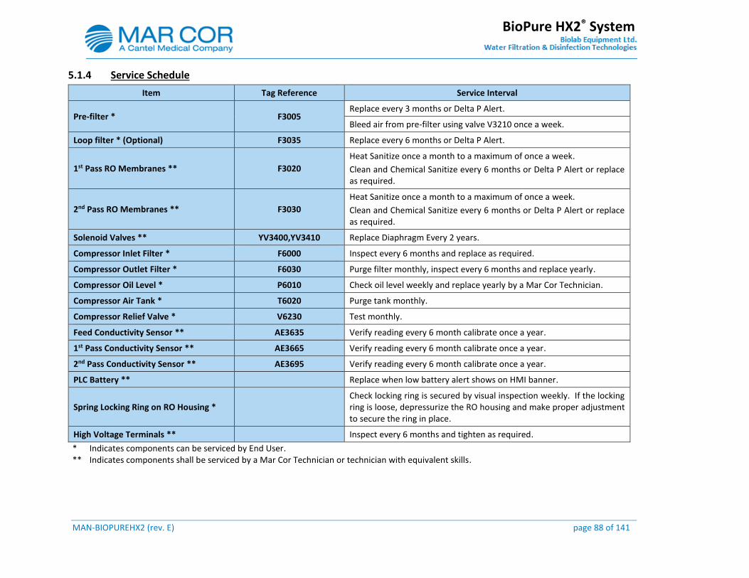
MAN-BIOPUREHX2 (rev. E) page 88 of 141
BioPure HX2® System
5.1.4 Service Schedule
Item Tag Reference Service Interval
Pre-filter * F3005 Replace every 3 months or Delta P Alert.
Bleed air from pre-filter using valve V3210 once a week.
Loop filter * (Optional) F3035 Replace every 6 months or Delta P Alert.
1st Pass RO Membranes ** F3020
Heat Sanitize once a month to a maximum of once a week.
Clean and Chemical Sanitize every 6 months or Delta P Alert or replace as required.
2nd Pass RO Membranes ** F3030
Heat Sanitize once a month to a maximum of once a week.
Clean and Chemical Sanitize every 6 months or Delta P Alert or replace as required.
Solenoid Valves ** YV3400,YV3410 Replace Diaphragm Every 2 years.
Compressor Inlet Filter * F6000 Inspect every 6 months and replace as required.
Compressor Outlet Filter * F6030 Purge filter monthly, inspect every 6 months and replace yearly.
Compressor Oil Level * P6010 Check oil level weekly and replace yearly by a Mar Cor Technician.
Compressor Air Tank * T6020 Purge tank monthly.
Compressor Relief Valve * V6230 Test monthly.
Feed Conductivity Sensor ** AE3635 Verify reading every 6 month calibrate once a year.
1st Pass Conductivity Sensor ** AE3665 Verify reading every 6 month calibrate once a year.
2nd Pass Conductivity Sensor ** AE3695 Verify reading every 6 month calibrate once a year.
PLC Battery ** Replace when low battery alert shows on HMI banner.
Spring Locking Ring on RO Housing * Check locking ring is secured by visual inspection weekly. If the locking ring is loose, depressurize the RO housing and make proper adjustment to secure the ring in place.
High Voltage Terminals ** Inspect every 6 months and tighten as required.
* Indicates components can be serviced by End User. ** Indicates components shall be serviced by a Mar Cor Technician or technician with equivalent skills.
MAN-BIOPUREHX2 (rev. E) page 89 of 141
BioPure HX2® System
5.1.5 Alarm ∕ Alert Log Sheet
Alarm Log
Time Alarm Condition Corrective Measure
MAN-BIOPUREHX2 (rev. E) page 90 of 141
BioPure HX2® System
CLEANING OVERVIEW
This overview provides general information about the usual foulants affecting the performance of Composite Polyamide Reverse Osmosis (RO) membrane elements and the removal of these foulants.
NOTE: The Composite Polyamide type of RO membrane elements may not be exposed to chlorinated water under any circumstances. Any such exposure will cause irreparable damage to the membrane. Absolute care must be taken following any disinfection of piping or equipment or the preparation of cleaning or storage solutions to ensure that no trace of chlorine is present in the feed water to the RO membrane elements.
NOTE: It is recommended that all RO membrane cleaning operations should be closely coordinated with Mar Cor during the RO membrane element warranty period. Mar Cor field service personnel are available to be on site for cleaning assistance, should the need arise. Please contact Mar Cor for current charges for this service.
NOTE: The use of cationic surfactant should be avoided in cleaning solutions, since irreversible fouling of the membrane elements may occur.
During normal operation over a period of time, RO membrane elements are subject to fouling by suspended or sparingly soluble materials that may be present in the feed water. Common examples of foulants are:
1. Calcium carbonate scale 2. Sulfate scale of calcium, barium or strontium 3. Metal oxides (iron, manganese, copper, nickel, aluminum, etc.) 4. Polymerized silica scale 5. Inorganic colloidal deposits 6. Mixed inorganic/organic colloidal deposits 7. NOM (Natural Organic Matter) 8. Man-made organic material (e.g. antiscalant/dispersants, cationic polyelectrolytes) 9. Biological (bacterial bioslime, algae, mold, or fungi)
The nature and rapidity of fouling depends on a number of factors, such as the quality of the feed water and the system recovery rate. Typically, fouling is progressive, and if not controlled early, will impair the RO membrane element performance in a relatively short time. Cleaning should occur when the RO shows evidence of fouling, just prior to a long-term shutdown, or as a matter of scheduled routine maintenance. The elements shall be maintained in a clean or “nearly clean” condition to prevent excessive fouling by the foulants listed above. Some fouling is allowed as long as:
1. Normalized permeate flow decrease is less than 10%. 2. Normalized permeate quality decrease is less than 10%. 3. Normalized pressure drop, as measured between the feed and concentrate headers, increase
is less than 15%.
MAN-BIOPUREHX2 (rev. E) page 91 of 141
BioPure HX2® System
Cleaning should be carried out before these values are exceeded to maintain the elements in a clean or “nearly clean” condition. Effective cleaning is evidenced by the return of the normalized parameters to their initial, Start-up, value. In the event you do not normalize your operating data, the above values still apply if you do not have major changes in critical operating parameters. The operating parameters that have to stay constant are permeate flow, permeate back-pressure, recovery, temperature, and feed TDS. If these operating parameters fluctuate, then it is highly recommended that you normalize the data to determine if fouling is occurring or if the RO is actually operating normally based on the change in a critical operating parameter.
Monitoring overall plant performance on a regular basis is an essential step in recognizing when membrane elements are becoming fouled. Performance is affected progressively and in varying degrees, depending on the nature of the foulants.
RO cleaning frequency due to fouling will vary by site. A rough rule of thumb as to an acceptable cleaning frequency is once every 3 to 12 months. If you have to clean more than once a month, you should be able to justify further capital expenditures for improved RO pre-treatment or a re-design of the system, contact Mar Cor. If the cleaning frequency is every one to three months, you may want to focus on improving the operation of your existing equipment but further capital expenditure may be harder to justify.
It is important to clean the membranes when they are only lightly fouled, not heavily fouled. Heavy fouling can impair the effectiveness of the cleaning chemical by impeding the penetration of the chemical deep into the foulant and in the flushing of the foulant out of the elements. If normalized membrane performance drops 30 to 50%, it may be impossible to fully restore the performance back to baseline conditions.
One RO design feature that is commonly overlooked in reducing RO cleaning frequency is the use of RO permeate water for flushing foulants from the system. Soaking the RO elements during standby with permeate can help dissolve scale and loosen precipitates, reducing the frequency of chemical cleaning.
What you clean for can vary from site to site depending on the foulant. Complicating the situation frequently is that more than one foulant can be present, which explains why cleanings frequently require a low pH and high pH cleaning regiment.
NOTE: The membrane elements shall not be exposed to feed water containing oil, grease, or other foreign matter which proves to chemically or physically damage the integrity of the membrane.
SANITIZATION OVERVIEW
The performance requirement of purified water equipment is generally based on measurement of conductivity and total organic carbon (TOC) in the product water. An additional requirement for the medical, biotechnical, and pharmaceutical industries is the monitoring of viable microbes and endotoxins limits. In order to meet these limits, specific sanitization processes are used to
MAN-BIOPUREHX2 (rev. E) page 92 of 141
BioPure HX2® System
disinfect and maintain the purified water equipment, allowing the product water to consistently meet requirements set by ISO 13959-11 standards. Therefore, from a regulatory perspective, the end user of the purified water equipment is obligated to ensure these processes are set in place in order to ensure these requirements are met. Today, it is common for end user protocols to stipulate very low, viable microbe and endotoxin levels in their product water.
In general, ambient operating temperatures and the absence of chlorine or other disinfectants in the water can create a microbe breeding environment on the surface of RO membranes. To attain better system control over microbe levels, end users have employed routine chemical sanitization processes where the cleaning frequency is often based on the bacterial level measured in the product water.
Chemicals used in RO membrane cleaning procedures include low and high pH-based cleaners for the primary purpose of removing hardness scale and organic deposits that may build up on the membrane surface. Some microbiological control is also achieved as a secondary benefit.
NOTE: The RO system must be chemical cleaned or chemical sanitized by highly skilled personnel. Contact Mar Cor representative for assistance to perform appropriate cleaning procedures in the field.
Bacteria counts taken from water streams are typically representative of the “loose” microbes in the stream and not necessarily of microbes that may exist in a biofilm within the water system. Biofilms are a complex organization of microbes formed by one of many common species, which adhere to a surface and cover themselves from the fluid stream in a somewhat protective polysaccharide boundary layer.
Biofilms form naturally but the growth may be mitigated with appropriate fluid velocity, smooth sanitary pipe designs, and periodic and appropriate sanitization processes. However biofilm has proven to be quite resilient to many chemical sanitization processes due to their protective boundary layer. Studies demonstrate biofilms may survive even after 60 minutes of exposure to chlorine-based sanitizing chemicals. Preventing the formation of biofilms, therefore, is a primary goal with respect to “regular and periodic” sanitization processes.
Although many chemical sanitization processes may be somewhat ineffective against biofilms, based on specific chemicals, exposure time and frequency of application, the sub-boundary layer bacterial colony cannot escape exposure to sanitizing temperatures during a hot water sanitization process.
Effective sanitization with hot water is accomplished through an appropriate combination of exposure time and temperature. While not officially established, the industry has “standardized’ 80oC (176oF) for 30 to 60 minutes as the optimum sanitization target point.
A primary use for hot water sanitization is to inactivate viable microbes. However, it must be noted that endotoxin reduction is not achieved as a direct result of the hot water sanitization process. Based on the feed water source, system operating conditions and the end user’s preventative maintenance practices, traditional chemical cleaning processes may still be
MAN-BIOPUREHX2 (rev. E) page 93 of 141
BioPure HX2® System
required. Generally, hot water cleanings are performed more frequently than chemical cleanings, based on microbe counts and/or regular sanitization schedule.
CHEMICAL SELECTION AND USE OF CLEANING CHEMICALS
There are a number of factors involved in the selection of a suitable cleaning chemical (or chemicals) and proper cleaning protocol. The first time you have to perform a cleaning, it is recommended to contact the manufacturer of the equipment, the RO element manufacturer, or a RO specialty chemical and service supplier. Once the suspected foulant(s) are identified, one or more cleaning chemicals will be recommended. These cleaning chemical(s) can be generic or can be private-labeled proprietary chemicals. Typically, the generic chemicals can be of technical grades and are available from local chemical supply companies. The proprietary RO cleaning chemicals can be more expensive, but may be easier to use and one cannot rule out the advantage of the intellectual knowledge supplied by these companies. Some independent RO service companies can determine the proper chemicals and cleaning protocol for your situation by testing a fouled element pulled from your system at their facility.
It is not unusual to use a number of different cleaning chemicals in a specific sequence to achieve the optimum cleaning. Typically, a high pH cleaning is used first to remove foulants like oil or biological matter, followed by a low pH cleaning to remove foulants like mineral scale or metal oxides/hydroxides fouling. There are times that order of high and low pH cleaning solutions is reversed or one solution only is required to clean the membranes. Some cleaning solutions have detergents added to aid in the removal of heavy biological and organic debris, while others have a chelating agent like EDTA added to aid in the removal of colloidal material, organic and biological material, and sulfate scale. An important thing to remember is that the improper selection of a cleaning chemical, or the sequence of chemical introduction, can make the foulant worse.
Mar Cor recommends that the membrane system operator thoroughly investigate the signs of fouling before they select a cleaning chemical and a cleaning protocol. Some forms of fouling (iron deposits and scaling commonly associated with well waters) may require only a simple low pH cleaning. However, for most complex fouling phenomena, a multi-step solution is often required.
NOTE: The RO system must be chemical cleaned or chemical sanitized by highly skilled personnel. Contact Mar Cor representative for assistance to perform appropriate cleaning procedures in the field.
GENERAL PRECAUTIONS IN CLEANING CHEMICAL SELECTION AND USAGE
NOTE: When using a proprietary chemical, make sure the chemical has been qualified for use with your membrane by the chemical supplier. The chemical supplier’s
MAN-BIOPUREHX2 (rev. E) page 94 of 141
BioPure HX2® System
instructions should not be in conflict with the manufacturer’s recommended cleaning parameters and limits listed in this overview.
NOTE: When using generic chemicals, make sure the chemical has been qualified for use with your membrane in this overview.
NOTE: Use the least harsh cleaning regiment to get the job done. This includes the cleaning parameters of pH, temperature, and contact time. This will optimize the useful life of the membrane.
NOTE: Clean at the recommended target temperatures to optimize cleaning efficiency and membrane life.
NOTE: Use the minimum amount of chemical contact time to optimize membrane life.
NOTE: Be prudent in the adjustment of pH at the low and high pH range to extend the useful life of the membrane. A “gentle” pH range is 4 to 10, while the harshest is 2 to 4 and 10 to 12.
NOTE: Oil and biologically-fouled membranes should not use a low pH clean-up first as the oil and biological matter will congeal.
NOTE: Cleaning and flushing flows should be in the same direction as the normal feed flow to avoid potential telescoping and element damage.
NOTE: When cleaning a multi-stage RO, the most effective cleaning is one stage at a time so cleaning flow velocities can be optimized and foulants from upstream stages do not have to pass through downstream stages.
NOTE: Flushing out detergents with higher pH permeate water can reduce foaming problems.
NOTE: Verify that proper disposal requirements for the cleaning solution are followed.
NOTE: If the system has been fouled biologically, you may want to consider the extra step of introducing a sanitizing biocide chemical before and after a successful cleaning. Biocides can be introduced before and immediately after cleaning, periodically (e.g. once a week), or continuously during service. User must be sure that the biocide is compatible with the membrane, does not create any health risks, is effective in controlling biological activity, and is not cost prohibitive.
CAUTION: For safety reasons, make sure all hoses and piping can handle the temperatures, pressures and pH’s encountered during a cleaning.
CAUTION: For safety reasons, always add chemicals slowly to an agitated batch of make-up water.
CAUTION: For safety reasons, always wear safety glasses and protective gear when working with chemicals.
MAN-BIOPUREHX2 (rev. E) page 95 of 141
BioPure HX2® System
CAUTION: For safety reasons, do not mix acids with caustics. Thoroughly rinse any cleaning solution from the RO system before introducing the next solution.
CAUTION: When performing a cleaning/sanitization it is very important to use the proper safety apparatus. Refer to the Material Safety Data Sheet (MSDS) provided with the sanitant or cleaner before using it. Carefully follow the manufacturer’s safety instructions on the labels affixed to the chemical containers.
NOTE: After each batch of solution is used, the local municipality may require it to be neutralized before discharging. Check the local municipality for waste discharge regulations.
CLEANING/SANITIZATION FREQUENCY
It is recommended that a cleaning be performed every 6 month on the first pass membrane or anytime a pre-treatment upset has occurred. A full system (1st pass, 2nd pass, and loop) sanitization with MINNCARE® Disinfectant should also be performed every 6 months.
NOTE: The RO system must be chemical cleaned or chemical sanitized by highly skilled personnel. Contact Mar Cor representative to provide assistance to perform appropriate cleaning in the field.
RO CLEANING/SANITIZATION CHEMICALS
The following cleaners have been evaluated and found to be compatible with the membrane elements. In addition to the generic cleaners listed below, there are many chemical companies that market membrane cleaners. For best results, use Mar Cor’s recommended brands for antiscalants and cleaners for your specific elements.
Type of Foulant Chemical
Mineral scale and metal precipitates HCl or citric acid, pH 2
Organics, silt, bacterial slime Sodium hydroxide, pH 12.5
Bacteria MINNCARE® Disinfectant, 1%
RO CLEANING/SANITIZATION CHEMICALS CONCENTRATIONS
The following cleaners have been evaluated and found to be compatible with the membrane element.
Chemical Used Quantity When Diluted In 189.3 Litres (50 Gallons) Of RO Quality Water Or Better
12N Hydrochloric Acid 1 litre (0.25 gallons), pH 2.5
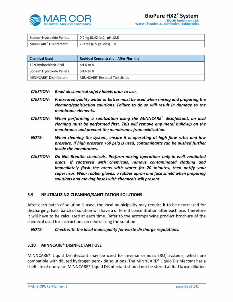
MAN-BIOPUREHX2 (rev. E) page 96 of 141
BioPure HX2® System
Sodium Hydroxide Pellets 0.2 Kg (0.42 lbs), pH 12.5
MINNCARE® Disinfectant 2 litres (0.5 gallons), 1%
Chemical Used Residual Concentration After Flushing
12N Hydrochloric Acid pH 6 to 8
Sodium Hydroxide Pellets pH 6 to 8
MINNCARE® Disinfectant MINNCARE® Residual Test Strips
CAUTION: Read all chemical safety labels prior to use.
CAUTION: Pretreated quality water or better must be used when rinsing and preparing the cleaning/sanitization solutions. Failure to do so will result in damage to the membrane elements.
CAUTION: When performing a sanitization using the MINNCARE® disinfectant, an acid cleaning must be performed first. This will remove any metal build-up on the membranes and prevent the membranes from oxidization.
NOTE: When cleaning the system, ensure it is operating at high flow rates and low pressure. If high pressure >60 psig is used, contaminants can be pushed further inside the membranes.
CAUTION: Do Not Breathe chemicals. Perform mixing operations only in well ventilated areas. If spattered with chemicals, remove contaminated clothing and immediately flush the areas with water for 20 minutes, then notify your supervisor. Wear rubber gloves, a rubber apron and face shield when preparing solutions and moving hoses with chemicals still present.
NEUTRALIZING CLEANING/SANITIZATION SOLUTIONS
After each batch of solution is used, the local municipality may require it to be neutralized for discharging. Each batch of solution will have a different concentration after each use. Therefore it will have to be calculated at each time. Refer to the accompanying product brochure of the chemical used for instructions on neutralizing the solution.
NOTE: Check with the local municipality for waste discharge regulations.
MINNCARE® DISINFECTANT USE
MINNCARE® Liquid Disinfectant may be used for reverse osmosis (RO) systems, which are compatible with diluted hydrogen peroxide solutions. The MINNCARE® Liquid Disinfectant has a shelf life of one year. MINNCARE® Liquid Disinfectant should not be stored at its 1% use dilution
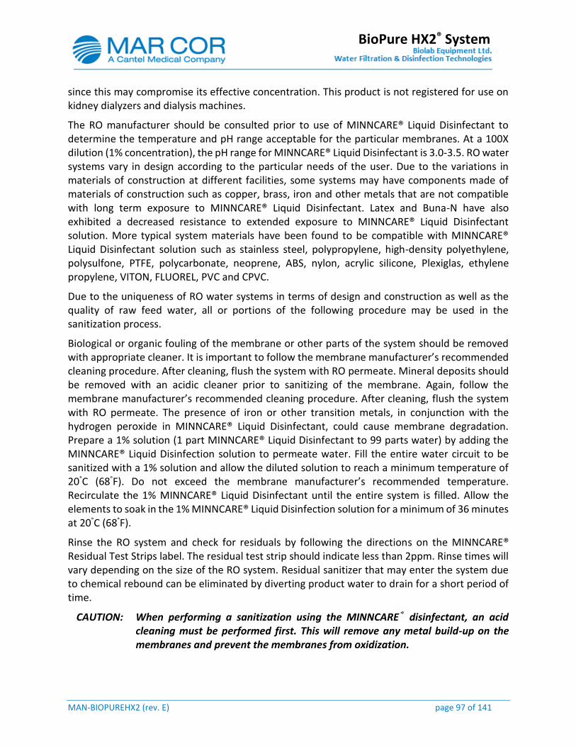
MAN-BIOPUREHX2 (rev. E) page 97 of 141
BioPure HX2® System
since this may compromise its effective concentration. This product is not registered for use on kidney dialyzers and dialysis machines.
The RO manufacturer should be consulted prior to use of MINNCARE® Liquid Disinfectant to determine the temperature and pH range acceptable for the particular membranes. At a 100X dilution (1% concentration), the pH range for MINNCARE® Liquid Disinfectant is 3.0-3.5. RO water systems vary in design according to the particular needs of the user. Due to the variations in materials of construction at different facilities, some systems may have components made of materials of construction such as copper, brass, iron and other metals that are not compatible with long term exposure to MINNCARE® Liquid Disinfectant. Latex and Buna-N have also exhibited a decreased resistance to extended exposure to MINNCARE® Liquid Disinfectant solution. More typical system materials have been found to be compatible with MINNCARE® Liquid Disinfectant solution such as stainless steel, polypropylene, high-density polyethylene, polysulfone, PTFE, polycarbonate, neoprene, ABS, nylon, acrylic silicone, Plexiglas, ethylene propylene, VITON, FLUOREL, PVC and CPVC.
Due to the uniqueness of RO water systems in terms of design and construction as well as the quality of raw feed water, all or portions of the following procedure may be used in the sanitization process.
Biological or organic fouling of the membrane or other parts of the system should be removed with appropriate cleaner. It is important to follow the membrane manufacturer’s recommended cleaning procedure. After cleaning, flush the system with RO permeate. Mineral deposits should be removed with an acidic cleaner prior to sanitizing of the membrane. Again, follow the membrane manufacturer’s recommended cleaning procedure. After cleaning, flush the system with RO permeate. The presence of iron or other transition metals, in conjunction with the hydrogen peroxide in MINNCARE® Liquid Disinfectant, could cause membrane degradation. Prepare a 1% solution (1 part MINNCARE® Liquid Disinfectant to 99 parts water) by adding the MINNCARE® Liquid Disinfection solution to permeate water. Fill the entire water circuit to be sanitized with a 1% solution and allow the diluted solution to reach a minimum temperature of 20°C (68°F). Do not exceed the membrane manufacturer’s recommended temperature. Recirculate the 1% MINNCARE® Liquid Disinfectant until the entire system is filled. Allow the elements to soak in the 1% MINNCARE® Liquid Disinfection solution for a minimum of 36 minutes at 20°C (68°F).
Rinse the RO system and check for residuals by following the directions on the MINNCARE® Residual Test Strips label. The residual test strip should indicate less than 2ppm. Rinse times will vary depending on the size of the RO system. Residual sanitizer that may enter the system due to chemical rebound can be eliminated by diverting product water to drain for a short period of time.
CAUTION: When performing a sanitization using the MINNCARE® disinfectant, an acid cleaning must be performed first. This will remove any metal build-up on the membranes and prevent the membranes from oxidization.

MAN-BIOPUREHX2 (rev. E) page 98 of 141
BioPure HX2® System
MINNCARE® Liquid Disinfectant may be used for reverse osmosis (RO) systems, which are compatible with diluted hydrogen peroxide solutions. The MINNCARE® Liquid Disinfectant has a shelf life of one year. MINNCARE® Liquid Disinfectant should not be stored at its 1% use dilution since this may compromise its effective concentration. This product is not registered for use on kidney dialyzers and dialysis machines.
The RO manufacturer should be consulted prior to use of MINNCARE® Liquid Disinfectant to determine the temperature and pH range acceptable for the particular membranes. At a 100X dilution (1% concentration), the pH range for MINNCARE® Liquid Disinfectant is 3.0-3.5. RO water systems vary in design according to the particular needs of the user. Due to the variations in materials of construction at different facilities, some systems may have components made of materials of construction such as copper, brass, iron and other metals that are not compatible with long term exposure to MINNCARE® Liquid Disinfectant. Latex and Buna-N have also exhibited a decreased resistance to extended exposure to MINNCARE® Liquid Disinfectant solution. More typical system materials have been found to be compatible with MINNCARE® Liquid Disinfectant solution such as stainless steel, polypropylene, high-density polyethylene, polysulfone, PTFE, polycarbonate, neoprene, ABS, nylon, acrylic silicone, Plexiglas, ethylene propylene, VITON, FLUOREL, PVC and CPVC.
Due to the uniqueness of RO water systems in terms of design and construction as well as the quality of raw feed water, all or portions of the following procedure may be used in the sanitization process.
Biological or organic fouling of the membrane or other parts of the system should be removed with appropriate cleaner. It is important to follow the membrane manufacturer’s recommended cleaning procedure. After cleaning, flush the system with RO permeate. Mineral deposits should be removed with an acidic cleaner prior to sanitizing of the membrane. Again, follow the membrane manufacturer’s recommended cleaning procedure. After cleaning, flush the system with RO permeate. The presence of iron or other transition metals, in conjunction with the hydrogen peroxide in MINNCARE® Liquid Disinfectant, could cause membrane degradation. Prepare a 1% solution (1 part MINNCARE® Liquid Disinfectant to 99 parts water) by adding the MINNCARE® Liquid Disinfection solution to permeate water. Fill the entire water circuit to be sanitized with a 1% solution and allow the diluted solution to reach a minimum temperature of 20°C (68°F). Do not exceed the membrane manufacturer’s recommended temperature. Recirculate the 1% MINNCARE® Liquid Disinfectant until the entire system is filled. Allow the elements to soak in the 1% MINNCARE® Liquid Disinfection solution for a minimum of 36 minutes at 20°C (68°F).
Rinse the RO system and check for residuals by following the directions on the MINNCARE® Residual Test Strips label. The residual test strip should indicate less than 2ppm. Rinse times will vary depending on the size of the RO system. Residual sanitizer that may enter the system due to chemical rebound can be eliminated by diverting product water to drain for a short period of time.
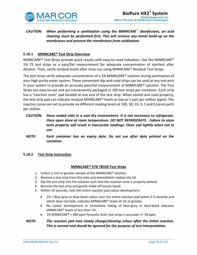
MAN-BIOPUREHX2 (rev. E) page 99 of 141
BioPure HX2® System
CAUTION: When performing a sanitization using the MINNCARE® disinfectant, an acid cleaning must be performed first. This will remove any metal build-up on the membranes and prevent the membranes from oxidization.
5.10.1 MINNCARE® Test Strip Overview
MINNCARE® Test Strips provide quick results with easy-to-read indicators. Use the MINNCARE® 1% TS test strips as a pass/fail measurement for adequate concentration of sterilant after dilution. Then, verify residual levels after rinse-out using MINNCARE® Residual Test Strips.
The test strips verify adequate concentration of a 1% MINNCARE® solution during sanitization of your high purity water system. These convenient dip-and-read strips can be used at any test port in your system to provide an accurate pass/fail measurement of MINNCARE® solution. The Test Strips are easy-to-use and are conveniently packaged in 100 test strips per container. Each strip has a “reaction zone” pad located at one end of the test strip. When stored and used properly, the test strip pad can indicate residual MINNCARE® levels as low as 1 part per million (ppm). The reaction zones are set to provide six different reading levels at 100, 30, 10, 3, 1 and 0 (zero) parts per million.
CAUTION: Store sealed vials in a cool dry environment. It is not necessary to refrigerate. Once open store at room temperature. DO NOT REFRIGERATE. Failure to store tests property will result in inaccurate readings. Close vial tightly when not in use.
NOTE: Each container has an expiry date. Do not use after date printed on the container.
5.10.2 Test Strip Instruction
MINNCARE® P/N 78339 Test Strips
1. Collect a 1ml or greater sample of the MINNCARE® solution. 2. Remove a test strip from the tube and immediately replace the lid. 3. Dip the test strip into the solution such that the reaction zone is properly wetted. 4. Remove the test strip and gently shake off excess liquid. 5. Within 10 seconds, note the entire reaction pad colour development.
1% = Blue-grey or blue-black colour over the entire reaction pad within 2-5 seconds and which does not fade, indicates MINNCARE® levels of 1% or greater.
No colour development or immediate fading of blue-grey or blue-black indicates MINNCARE® levels of less than 1%.
1% MINNCARE® = 400 ppm Peracetic Acid, test strips is accurate +/- 50 ppm.
NOTE: The reaction pad may slowly change/develop colour after the initial reaction. This is normal and should be ignored for the purpose of test interpretation.
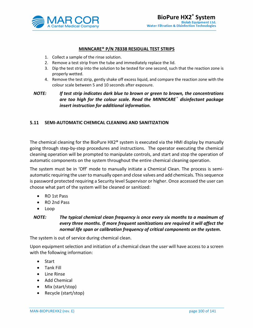
MAN-BIOPUREHX2 (rev. E) page 100 of 141
BioPure HX2® System
MINNCARE® P/N 78338 RESIDUAL TEST STRIPS
1. Collect a sample of the rinse solution. 2. Remove a test strip from the tube and immediately replace the lid. 3. Dip the test strip into the solution to be tested for one second, such that the reaction zone is
properly wetted. 4. Remove the test strip, gently shake off excess liquid, and compare the reaction zone with the
colour scale between 5 and 10 seconds after exposure.
NOTE: If test strip indicates dark blue to brown or green to brown, the concentrations are too high for the colour scale. Read the MINNCARE® disinfectant package insert instruction for additional information.
SEMI-AUTOMATIC CHEMICAL CLEANING AND SANITIZATION
The chemical cleaning for the BioPure HX2® system is executed via the HMI display by manually going through step-by-step procedures and instructions. The operator executing the chemical cleaning operation will be prompted to manipulate controls, and start and stop the operation of automatic components on the system throughout the entire chemical cleaning operation.
The system must be in ‘Off’ mode to manually initiate a Chemical Clean. The process is semi-automatic requiring the user to manually open and close valves and add chemicals. This sequence is password protected requiring a Security level Supervisor or higher. Once accessed the user can choose what part of the system will be cleaned or sanitized:
RO 1st Pass
RO 2nd Pass
Loop
NOTE: The typical chemical clean frequency is once every six months to a maximum of every three months. If more frequent sanitizations are required it will affect the normal life span or calibration frequency of critical components on the system.
The system is out of service during chemical clean.
Upon equipment selection and initiation of a chemical clean the user will have access to a screen with the following information:
Start
Tank Fill
Line Rinse
Add Chemical
Mix (start/stop)
Recycle (start/stop)

MAN-BIOPUREHX2 (rev. E) page 101 of 141
BioPure HX2® System
Neutralize (start/stop)
Tank Drain
Flush (start/stop)
RO Run To Drain (start/stop)
RO Run to Loop Drain (start/stop)
Complete
Recycle Timer 0-120 minutes (default 30)
Timer reset
The Chemical Clean process mode shall be displayed and the last chemical clean shall be recorded in the history.
XXXXX Chemical Clean Completed Started HH:MM:SS YYYY/MM/DD
Completed HH:MM:SS YYYY/MM/DD
5.11.1 Chemical Cleaning and Sanitization Preparation
Prior to performing a chemical cleaning or sanitization verify the following is completed.
1. Chemical quantities and types required are on hand and expiry dates are checked. 2. All chemical warnings and precautions labels are read and understood. 3. Appropriate personal safety equipment is on hand and worn during the execution of the
procedures. 4. Flow rates, pressures and water quality readings are recorded to determine if the cleaning
has improved the system performance. 5. Set the break tank level setpoint to the desired level. Add 37.9 litres (10 gallons) more to the
setpoint to compensate for the line rinse sequence. 6. Set the cleaning recycle timer to the desired time.
1ST PASS CHEMICAL CLEANING / SANITIZATION PROCEDURE
Security level Supervisor or higher is required to perform the following procedure. The HMI has built-in delays between each icon push to allow the system to transition smoothly. The time delay is shown on the status screen.
1. Press the Mode Control icon. 2. Place the system in OFF mode. 3. Press the Clean Mode icon. Press the 1st Pass icon. 4. Press the Screen Select icon. 5. Press the Status icon. 6. Press the Tank Fill icon:
a. Wait for the flows to equalize. b. Wait for the flush duration finish.
MAN-BIOPUREHX2 (rev. E) page 102 of 141
BioPure HX2® System
c. 2nd Pass quality check. 7. Wait for tank to fill to 35 gal. 8. Press the Line Rinse icon:
a. Tank level drains from 35 gal to 25 gal. 9. Press the Next icon. 10. Remove the 6”cap on top of the break tank and add the desired chemical. Then close the cap
when finished.
CAUTION: If performing a sanitization using the MINNCARE® disinfectant, an acid cleaning must be performed first. This will remove any metal build-up on the membranes and prevent oxidization on the membranes.
11. Press the Next icon. 12. Press the Chemical Mix followed by the Start Pump icon. After 5 minutes test the solution
concentration at sample valve V3205: a. If concentration is not within limits press the Stop Pump Icon and add more chemical. b. Press the Start Pump icon to continue mixing and check the solution concentration
again at sample valve V3205. 13. Allow the chemical mix timer to complete. 14. Press the Next icon. 15. Close the 2nd pass pump P3025 bypass valve V3260. 16. Press the Next icon. 17. Press the 1st Pass Recycle icon followed by the Start Pump icon. After 5 minutes test the
solution concentration at sample valve V3280: a. If concentration is not within limits press the Stop Pump icon and more chemical. b. Press the Start Pump icon to continue recycling and check the solution concentration
after 5-10 minutes at sample valve V3280. 18. The pump will stop once the cleaning counter elapses or the Pump Stop icon is pressed. 19. Press the Next icon. 20. Remove the 6” cap on top of the break tank and add chemical to the break tank to neutralize
the solution. Close the cap when finished. 21. Press the Next icon. 22. Press the Neutralization icon. After 5 minutes test the solution concentration at sample valve
V3205. Allow time run out: a. If concentration is not within limits press the Stop Pump icon and add more chemical. b. Press the Start Pump icon to continue neutralize and check the solution concentration
again at sample valve V3205. 23. Press the Next icon to confirm neutralization complete. 24. Press the Next icon to start tank drain. Allow drain cycle to complete. 25. Press the Next icon followed by the Flush icon. 26. Press the Screen Select icon followed by the Overview icon. Monitor the product water quality
AE3695. Once water quality begins to improve and stabilize, test for residual solution at sample valve V3280. If residual is not within limits allow the system to flush and re-check for residual in another 5 minutes.
27. Press the Screen Select icon. 28. Press the Status icon. 29. Press the Stop Pump icon once the residual is within limits.
MAN-BIOPUREHX2 (rev. E) page 103 of 141
BioPure HX2® System
30. Press the Next icon and open the 2nd pass pump P3025 bypass valve V3260. 31. Press the Next icon and wait for 5 minutes to allow system to settle. This will help dissipate
any hide out pockets of solution. 32. Press the RO Run To Drain icon. Then wait for:
a. The flows balance out. b. Flush duration finish. c. RO 2nd pass quality check.
33. Test for residual solution at sample valve V3280. If residual is not within limits, allow the system to run to drain and re-check for residual in another 5 minutes. Continue to run to drain until no residual is detected at sample valve V3280.
34. Press the Clean Complete icon. 35. Place the system back into normal operation or perform another cleaning / sanitization.
NOTE: After 15 minutes record the flow rates, pressures and water quality reading and determine if the cleaning has improved the system performance. If the performance has not improved, further cleanings / sanitizations could be required or membrane replacement.
36. The pre-filters F3005 are to be replaced after a cleaning is performed. Refer to section 5.15.1 for instructions.
NOTE: Once the system cleaning or sanitization is completed rinse the inside walls of the tank to flush away any residue using clean water.
2nd PASS CHEMICAL CLEANING / SANITIZATION PROCEDURE
Security level Supervisor or higher is required to perform the following procedure. The HMI has built in delays between each icon push to allow the system to transition smoothly. The time delay is shown on the Status screen
1. Press the Mode Control icon. 2. Place the system in OFF mode. 3. Please the Clean Mode icon. 4. Press the 2nd Pass icon. 5. Press the Screen Select icon. 6. Press the Status icon. 7. Press the Tank Fill icon:
a. Wait for the flows to equalize. b. Wait for the flush duration finish. c. 2nd Pass quality check.
8. Wait for tank to fill to 35 gal. 9. Press the Line Rinse icon:
a. Tank level drains from 35 gal to 25 gal. 10. Press the Next icon.

MAN-BIOPUREHX2 (rev. E) page 104 of 141
BioPure HX2® System
11. Remove the 6”cap on top of the break tank and add the desired chemical. Then close the cap when finished.
CAUTION: If performing a sanitization using the MINNCARE® disinfectant, an acid cleaning must be performed first. This will remove any metal build-up on the membranes and prevent oxidization on the membranes.
12. Press the Next icon. 13. Press the Chemical Mix followed by the Start Pump icon. After 5 minutes test the solution
concentration at sample valve V3205: a. If concentration is not within limits press the Stop Pump Icon and add more chemical. b. Press the Start Pump icon to continue mixing and check the solution concentration
again at sample valve V3205. 14. Allow the chemical mix timer to complete. 15. Press the Next icon. 16. Close the 1st pass feed valve V3230. 17. Press the Next icon. 18. Acknowledge that the valve 3230 is closed by pressing the Next icon. 19. Press the 2nd Pass Recycle icon followed by the Start Pump icon. After 5 minutes test the
solution concentration at sample valve V3280: a. If concentration is not within limits press the Stop Pump icon and add more chemical. b. Press the Start Pump icon to continue recycling and check the solution concentration
after 5-10 minutes at sample valve V3280. 20. The pump will stop once the cleaning counter elapses or the Stop Pump icon is pressed. 21. Press the Next icon. 22. Remove the 6”cap on top of the break tank and add chemical to the break tank to neutralize
the solution. Close the cap when finished. 23. Press the Next icon. 24. Press the Neutralization icon. 25. Press the Start Pump icon. 26. After 5 minutes test the solution concentration at sample valve V3205. Allow time run out:
a. If concentration is not within limits press the Stop Pump icon and add more chemical. b. Press the Start Pump icon to continue neutralize and check the solution concentration
again at sample valve V3205. 27. Press the Next icon to confirm neutralization complete. 28. Press the Next icon to start tank drain. Allow drain cycle to complete. 29. Press the Next icon followed by the Flush icon. 30. Press the Screen Select icon followed by the Overview icon. Monitor the product water quality
AE3695. Once water quality begins to improve and stabilize, test for residual solution at sample valve V3280. If residual is not within limits allow the system to flush and re-check for residual in another 5 minutes.
31. Press the Screen Select icon. 32. Press the Status icon. 33. Press the Stop Pump icon once the residual is within limits. 34. Press the Next icon and open the 2nd pass pump P3025 bypass valve V3260. 35. Press the Next icon and wait for 5 minutes to allow system to settle. This will help dissipate
any hide out pockets of solution.
MAN-BIOPUREHX2 (rev. E) page 105 of 141
BioPure HX2® System
36. Press the RO Run To Drain icon. Then wait for: a. The flows balance out. b. Flush duration finish. c. RO 2nd pass quality check.
37. Test for residual solution at sample valve V3280. If residual is not within limits, allow the system to run to drain and re-check for residual in another 5 minutes. Continue to run to drain until no residual is detected at sample valve V3280.
38. Press the Clean Complete icon.
NOTE: After 15 minutes record the flow rates, pressures and water quality reading and determine if the cleaning has improved the system performance. If the performance has not improved further cleanings / sanitizations could be required or membrane replacement.
39. The pre-filters F3005 are to be replaced after a cleaning is performed. Refer to section 5.15.1 for instructions.
40. Press Screen Select icon. 41. Place the system back into normal operation or perform another cleaning / sanitization.
NOTE: Once the system cleaning or sanitization is completed rinse the inside walls of the tank to flush away any residue using clean water.
LOOP CHEMICAL CLEANING / SANITIZATION PROCEDURE
Security level Supervisor or higher is required to perform the following procedure. The HMI has built in delays between each icon push to allow the system to transition smoothly. The time delay is shown on the Status screen.
1. Place the system in ‘Off’ mode. 2. Press the Mode Control icon. 3. Press the Loop icon under the clean mode heading. 4. Press the Screen Select icon. 5. Press the Status icon. 6. Press the Tank Fill icon and allow the tank to fill:
a. Wait for the flows to equalize. b. Wait for the flush duration finish. c. 2nd Pass quality check.
7. Wait for tank to fill to 35 gal. 8. Press the Line Rinse icon. 9. Tank level drains from 35 gal to 25 gal. 10. Press the Next Icon. 11. Remove the 6”cap on top of the break tank and add the desired chemical. Then close the cap
when finished. 12. Press the Next icon. 13. Press the Chemical Mix followed by the Start Pump icon. After 5 minutes test the solution
concentration at sample valve V3205: a. If concentration is not within limits press the Stop Pump Icon and add more chemical.
MAN-BIOPUREHX2 (rev. E) page 106 of 141
BioPure HX2® System
b. Press the Start icon to continue mixing and check the solution concentration again at sample valve V3205.
14. Allow the chemical mix timer to complete. 15. Press the Next icon. 16. Press the Next icon. 17. Press the Loop Recycle followed by the Pump Start icon. After 10 minutes test the solution
concentration at sample valve V3215: a. If concentration is not within limits press the Stop Pump Icon and add more chemical. b. Press the Start Pump icon to continue recycling and check the solution concentration
again after 5-10 minutes at sample valve V3215. c. Draw off a small amount of chemical solution at each point of use to make sure the
solution makes contact with each point. 18. The pump will stop once the cleaning counter elapses or Stop Pump icon is pressed. 19. Press the Next icon. 20. Remove the 6”cap on top of the break tank and add the desired chemical. Then close the cap
when finished. 21. Press Next icon. 22. Press the Loop Neutralization icon. After 10 minutes test the solution concentration at sample
valve V3205: a. If concentration is not within limits press the Stop Pump icon and more chemical. b. Press the Start icon to continue neutralize and check the solution concentration again
at sample valve V3205. 23. Press the Stop Pump icon if the solution concentration is within limits. 24. Press the Next icon. 25. Press the Next icon followed by the Tank Drain icon and allow the sequence to complete. 26. Press the Next icon followed by the Loop Flush icon.
NOTE: There is residual Minncare® solution in the feed water line of the system, and the system will indicate a bad quality alert while the Minncare® solution is flushing to drain. It will take approximately 10-15 minute before the water quality drops below setpoint and diverts to flush the loop.
27. After 15 minutes test for residual solution at sample valve V3215. Flush each point of use to drain and test for residual solution at those points. If residual is not within limits allow the system to flush and re-check for residual in another 5 minutes.
28. Press the Stop Pump icon once the residual is within limits. 29. Press the Clean Complete icon to finish the cleaning. At this point the system can be placed
back in operation or another cleaning / sanitization can be completed. 30. The pre-filters F3005 are to be replaced after a cleaning is performed. Refer to section 5.15.1
for instructions. 31. Press the Screen Select icon. 32. Press the Mode Control icon. 33. Place the system in normal operation.
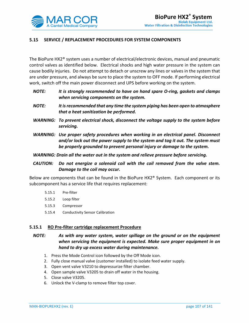
MAN-BIOPUREHX2 (rev. E) page 107 of 141
BioPure HX2® System
SERVICE / REPLACEMENT PROCEDURES FOR SYSTEM COMPONENTS
The BioPure HX2® system uses a number of electrical/electronic devices, manual and pneumatic control valves as identified below. Electrical shocks and high water pressure in the system can cause bodily injuries. Do not attempt to detach or unscrew any lines or valves in the system that are under pressure, and always be sure to place the system to OFF mode. If performing electrical work, switch off the main power disconnect and UPS before working on the system.
NOTE: It is strongly recommended to have on hand spare O-ring, gaskets and clamps when servicing components on the system.
NOTE: It is recommended that any time the system piping has been open to atmosphere that a heat sanitization be performed.
WARNING: To prevent electrical shock, disconnect the voltage supply to the system before servicing.
WARNING: Use proper safety procedures when working in an electrical panel. Disconnect and/or lock out the power supply to the system and tag it out. The system must be properly grounded to prevent personal injury or damage to the system.
WARNING: Drain all the water out in the system and relieve pressure before servicing.
CAUTION: Do not energize a solenoid coil with the coil removed from the valve stem. Damage to the coil may occur.
Below are components that can be found in the BioPure HX2® System. Each component or its subcomponent has a service life that requires replacement:
5.15.1 Pre-filter
5.15.2 Loop filter
5.15.3 Compressor
5.15.4 Conductivity Sensor Calibration
5.15.1 RO Pre-filter cartridge replacement Procedure
NOTE: As with any water system, water spillage on the ground or on the equipment when servicing the equipment is expected. Make sure proper equipment in on hand to dry up excess water during maintenance.
1. Press the Mode Control icon followed by the Off Mode icon. 2. Fully close manual valve (customer installed) to isolate feed water supply. 3. Open vent valve V3210 to depressurize filter chamber. 4. Open sample valve V3205 to drain off water in the housing. 5. Close valve V3205. 6. Unlock the V-clamp to remove filter top cover.
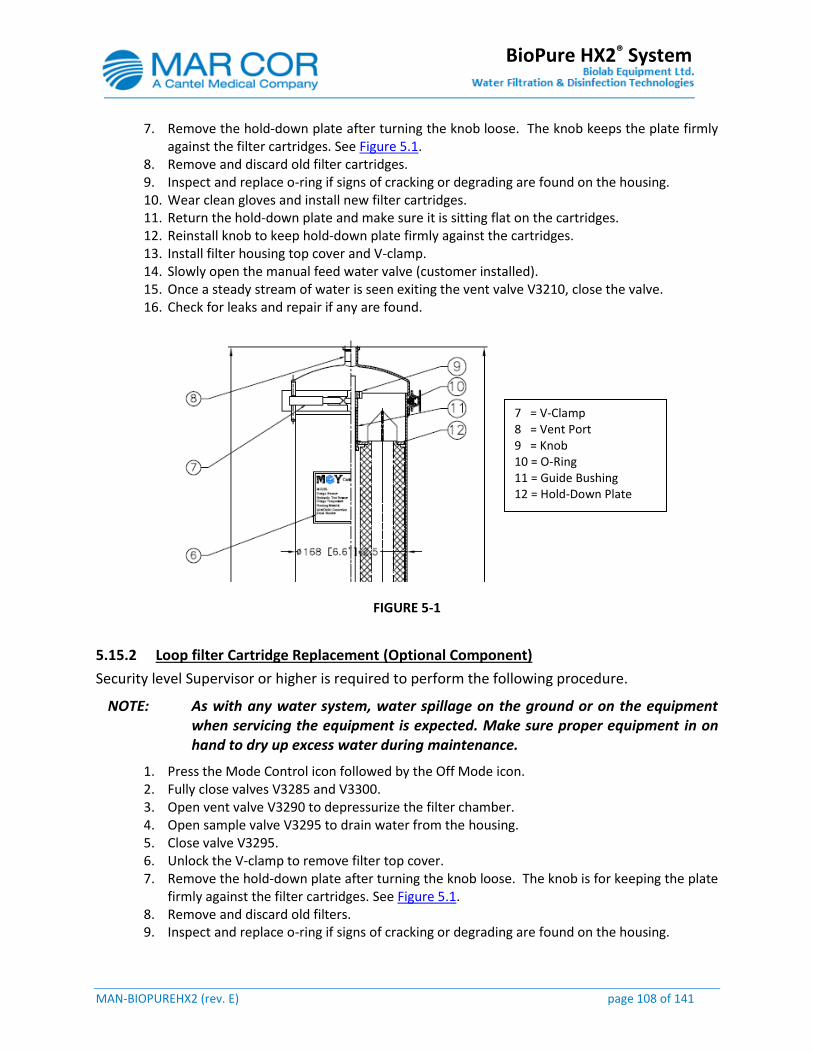
MAN-BIOPUREHX2 (rev. E) page 108 of 141
BioPure HX2® System
7. Remove the hold-down plate after turning the knob loose. The knob keeps the plate firmly against the filter cartridges. See Figure 5.1.
8. Remove and discard old filter cartridges. 9. Inspect and replace o-ring if signs of cracking or degrading are found on the housing. 10. Wear clean gloves and install new filter cartridges. 11. Return the hold-down plate and make sure it is sitting flat on the cartridges. 12. Reinstall knob to keep hold-down plate firmly against the cartridges. 13. Install filter housing top cover and V-clamp. 14. Slowly open the manual feed water valve (customer installed). 15. Once a steady stream of water is seen exiting the vent valve V3210, close the valve. 16. Check for leaks and repair if any are found.
FIGURE 5-1
5.15.2 Loop filter Cartridge Replacement (Optional Component)
Security level Supervisor or higher is required to perform the following procedure.
NOTE: As with any water system, water spillage on the ground or on the equipment when servicing the equipment is expected. Make sure proper equipment in on hand to dry up excess water during maintenance.
1. Press the Mode Control icon followed by the Off Mode icon. 2. Fully close valves V3285 and V3300. 3. Open vent valve V3290 to depressurize the filter chamber. 4. Open sample valve V3295 to drain water from the housing. 5. Close valve V3295. 6. Unlock the V-clamp to remove filter top cover. 7. Remove the hold-down plate after turning the knob loose. The knob is for keeping the plate
firmly against the filter cartridges. See Figure 5.1. 8. Remove and discard old filters. 9. Inspect and replace o-ring if signs of cracking or degrading are found on the housing.
7 = V-Clamp 8 = Vent Port 9 = Knob 10 = O-Ring 11 = Guide Bushing 12 = Hold-Down Plate

MAN-BIOPUREHX2 (rev. E) page 109 of 141
BioPure HX2® System
10. Wear clean gloves and install new filter cartridges. 11. Return the hold-down plate and make sure it is sitting flat on the cartridges. 12. Reinstall knob to keep hold-down plate firmly against the cartridges. 13. Install filter housing top cover and V-clamp. 14. Open valves V3285 and V3300. 15. Press the Maint Mode icon followed by the Loop Flush icon and allow the system to start-up. 16. Once a steady stream of water is seen exiting the vent valve V3290, close the valve. 17. Check for leaks and repair if any are found. 18. Press the Off Mode icon and then the Auto Mode icon followed by the Production icon. 19. Perform a loop heat sanitization. Refer to section 4.4
5.15.3 Compressor
The BioPure HX2 system is equipped with an air compressor that provides compressed air to the control valve and actuated valves. Periodic maintenance is required.
Purging the Compressor System of condensate:
This shall be performed once a month
1. Press the Mode Control icon followed by the Off Mode icon. 2. Locate the outlet filter F6030 and press the condensate drain push button valve V6260 to
drain out excess condensate.
3. Turn the compressor switch located on top of the tank to the off position. 4. Locate the tank T6020 purge valve V6275. Connect a small tube to the outlet and direct the
other end of the tube to a small plastic container.
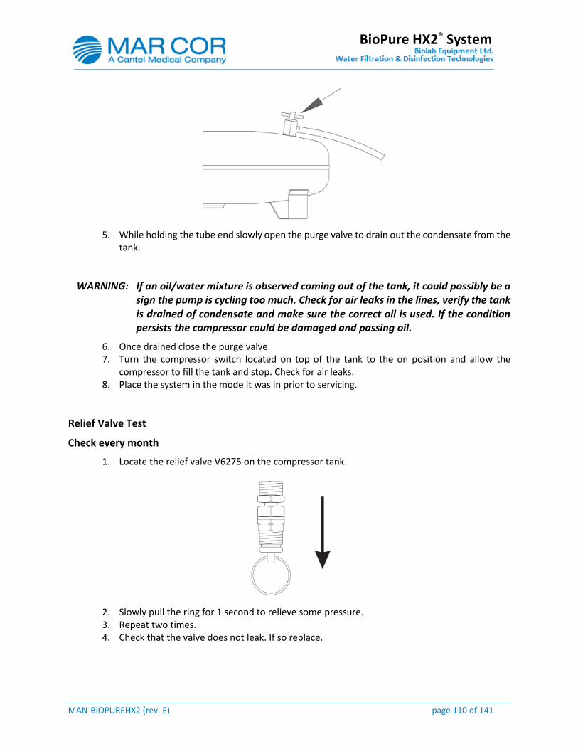
MAN-BIOPUREHX2 (rev. E) page 110 of 141
BioPure HX2® System
5. While holding the tube end slowly open the purge valve to drain out the condensate from the tank.
WARNING: If an oil/water mixture is observed coming out of the tank, it could possibly be a sign the pump is cycling too much. Check for air leaks in the lines, verify the tank is drained of condensate and make sure the correct oil is used. If the condition persists the compressor could be damaged and passing oil.
6. Once drained close the purge valve. 7. Turn the compressor switch located on top of the tank to the on position and allow the
compressor to fill the tank and stop. Check for air leaks. 8. Place the system in the mode it was in prior to servicing.
Relief Valve Test
Check every month
1. Locate the relief valve V6275 on the compressor tank.
2. Slowly pull the ring for 1 second to relieve some pressure. 3. Repeat two times. 4. Check that the valve does not leak. If so replace.
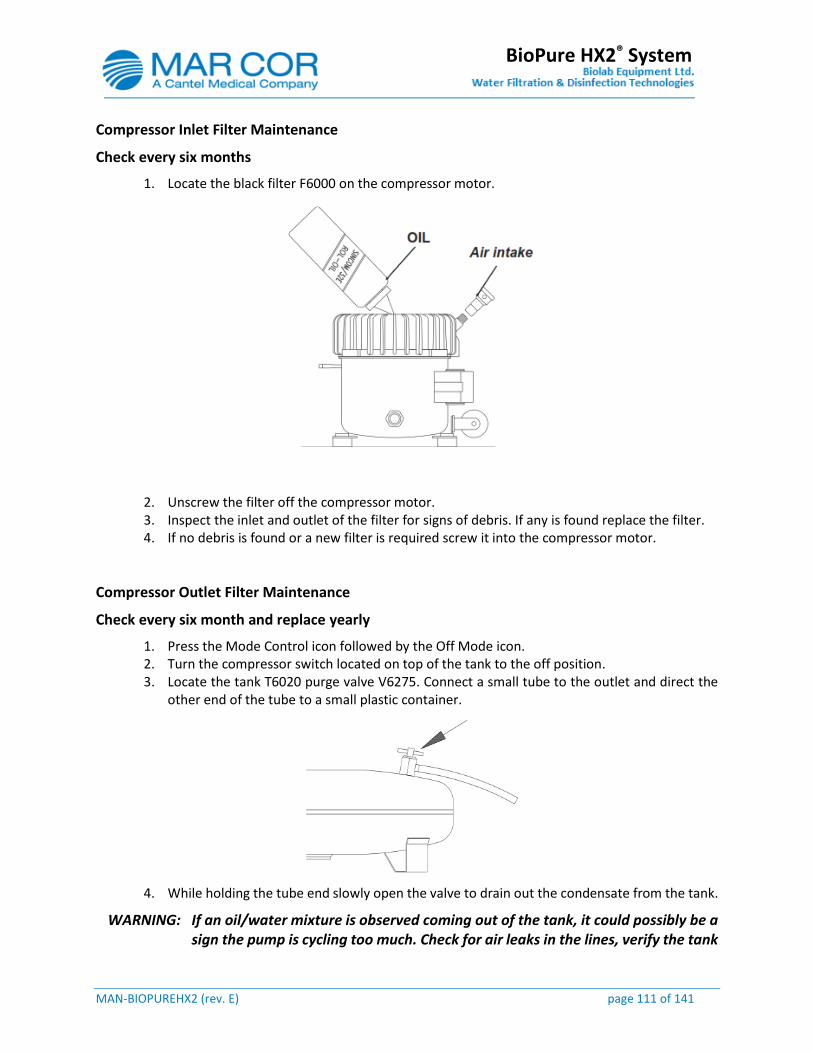
MAN-BIOPUREHX2 (rev. E) page 111 of 141
BioPure HX2® System
Compressor Inlet Filter Maintenance
Check every six months
1. Locate the black filter F6000 on the compressor motor.
2. Unscrew the filter off the compressor motor. 3. Inspect the inlet and outlet of the filter for signs of debris. If any is found replace the filter. 4. If no debris is found or a new filter is required screw it into the compressor motor.
Compressor Outlet Filter Maintenance
Check every six month and replace yearly
1. Press the Mode Control icon followed by the Off Mode icon. 2. Turn the compressor switch located on top of the tank to the off position. 3. Locate the tank T6020 purge valve V6275. Connect a small tube to the outlet and direct the
other end of the tube to a small plastic container.
4. While holding the tube end slowly open the valve to drain out the condensate from the tank.
WARNING: If an oil/water mixture is observed coming out of the tank, it could possibly be a sign the pump is cycling too much. Check for air leaks in the lines, verify the tank

MAN-BIOPUREHX2 (rev. E) page 112 of 141
BioPure HX2® System
is drained of condensate and make sure the correct oil is used. If the condition persists the compressor could be damaged and passing oil.
5. Close the purge valve V6275. 6. Unscrew the filter bowl F6030. Be careful not to lose the o-ring.
7. Look at the filter for signs of contamination without toughing it. Filter should be white. If signs of contamination unscrew the filter and replace with new one.
8. Screw in the filter bowl including the o-ring. 9. Turn the compressor switch located on top of the tank to the on position and allow the
compressor to fill the tank and stop. Check for air leaks. 10. Place the system in the mode it was in prior to servicing.
Ref. Werther P15-TC Man Rev 1.
5.15.4 Conductivity Transmitter Calibration Procedure
The BioPure HX2 system is equipped with a conductivity transmitter and sensors to measure the feed water, 1st pass product and 2nd pass product temperature and conductivity. The transmitter is located inside the top control panel. The procedure below describes the calibration of the conductivity meter. For maximum measurement accuracy the transmitter should be calibrated once every year.
NOTE: The transmitter must be calibrated by a Mar Cor Technician that is familiar with accessing and navigating the settings on the transmitter. General navigation and access instruction are not covered in this procedure. Refer to the transmitter operator manual.
NOTE: The sensors can be calibrated but only at the manufacturer. If sensor calibration is required it is recommended that spare sensors are purchased. Calibration certificates typically expire after one year so it the recommend that the spare sensor get calibrated close to the time when the sensor on the system calibration expires.
NOTE: Since the conductivity sensors used have a PT1000 RTD they do not need to be calibrated.
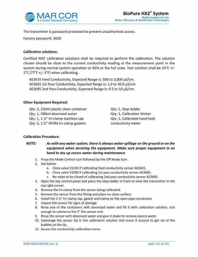
MAN-BIOPUREHX2 (rev. E) page 113 of 141
BioPure HX2® System
The transmitter is password protected to prevent unauthorized access.
Factory password: 3658
Calibration solutions:
Certified NIST calibration solutions shall be required to perform the calibration. The solution chosen should be close to the current conductivity reading at the measurement point in the system during normal system operation or 65% or the full scale. Test solution shall be 25°C +/- 2°C (77°F +/- 3°F) when calibrating.
AE3635 Feed Conductivity, Expected Range is: 500 to 3,000 µS/cm. AE3665 1st Pass Conductivity, Expected Range is: 1.0 to 50.0 µS/cm. AE3695 2nd Pass Conductivity, Expected Range is: 0.5 to 10 µS/cm.
Other Equipment Required:
Qty: 3, 250ml plastic clean container Qty: 1, 500ml deionized water Qty: 1, 1 ½” tri-clamp stainless cap Qty: 3, 1 ½” EPDM tri-clamp gaskets
Qty: 1, Step ladder Qty: 1, Calibration Sticker Qty: 1, Calibrated hand held conductivity meter
Calibration Procedure:
NOTE: As with any water system, there is always water spillage on the ground or on the equipment when servicing the equipment. Make sure proper equipment in on hand to dry up excess water during maintenance
1. Press the Mode Control icon followed by the Off Mode Icon. 2. See below:
a. Close valve V3230 if calibrating feed conductivity sensor AE3635. b. Close valve V3260 if calibrating 1st pass conductivity sensor AE3665. c. No valve to be closed of calibrating 2nd pass conductivity sensor AE3695.
3. Open the top control panel and place the step ladder in front to view the transmitter in the top right corner.
4. Remove the tri-clamp from the sensor being calibrated. 5. Remove the sensor from the fitting and place on clean surface. 6. Install the 1 ½” tri-clamp cap, gasket and clamp on the open pipe connection. 7. Inspect the sensor for signs of damage. 8. Rinse one of the containers with deionized water and fill it with calibration solution. Just
enough to submerse the 2” the sensor end. 9. Rinse the sensor with deionized water and give it shake to remove excess water. 10. Submerge the sensor tip in the calibration solution and move it around to get rid of the
bubbles at the tip. 11. Access the conductivity calibration menu.
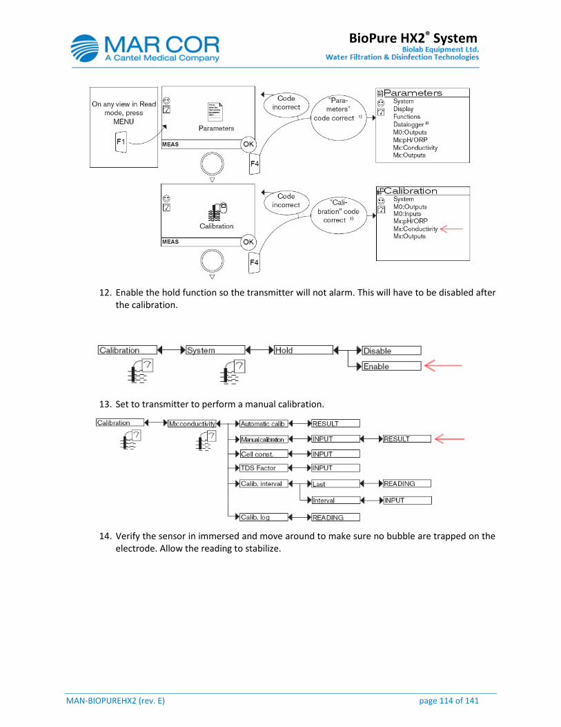
MAN-BIOPUREHX2 (rev. E) page 114 of 141
BioPure HX2® System
12. Enable the hold function so the transmitter will not alarm. This will have to be disabled after the calibration.
13. Set to transmitter to perform a manual calibration.
14. Verify the sensor in immersed and move around to make sure no bubble are trapped on the electrode. Allow the reading to stabilize.
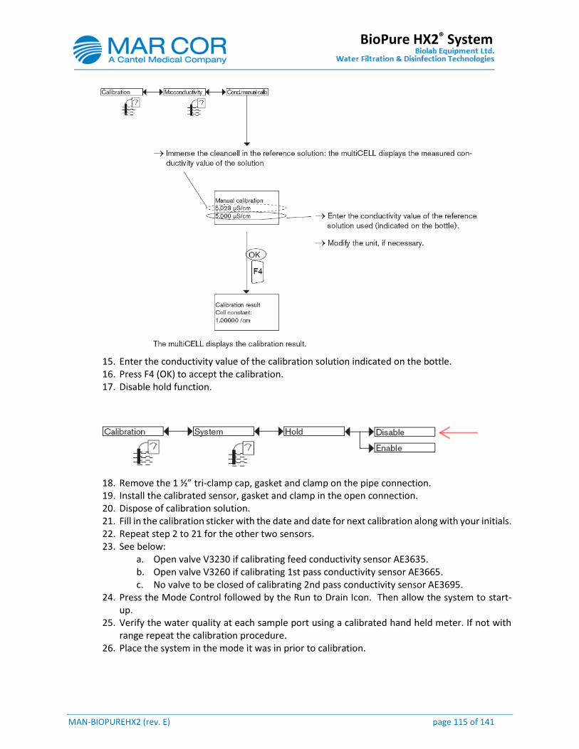
MAN-BIOPUREHX2 (rev. E) page 115 of 141
BioPure HX2® System
15. Enter the conductivity value of the calibration solution indicated on the bottle. 16. Press F4 (OK) to accept the calibration. 17. Disable hold function.
18. Remove the 1 ½” tri-clamp cap, gasket and clamp on the pipe connection. 19. Install the calibrated sensor, gasket and clamp in the open connection. 20. Dispose of calibration solution. 21. Fill in the calibration sticker with the date and date for next calibration along with your initials. 22. Repeat step 2 to 21 for the other two sensors. 23. See below:
a. Open valve V3230 if calibrating feed conductivity sensor AE3635. b. Open valve V3260 if calibrating 1st pass conductivity sensor AE3665. c. No valve to be closed of calibrating 2nd pass conductivity sensor AE3695.
24. Press the Mode Control followed by the Run to Drain Icon. Then allow the system to start-up.
25. Verify the water quality at each sample port using a calibrated hand held meter. If not with range repeat the calibration procedure.
26. Place the system in the mode it was in prior to calibration.

MAN-BIOPUREHX2 (rev. E) page 116 of 141
BioPure HX2® System
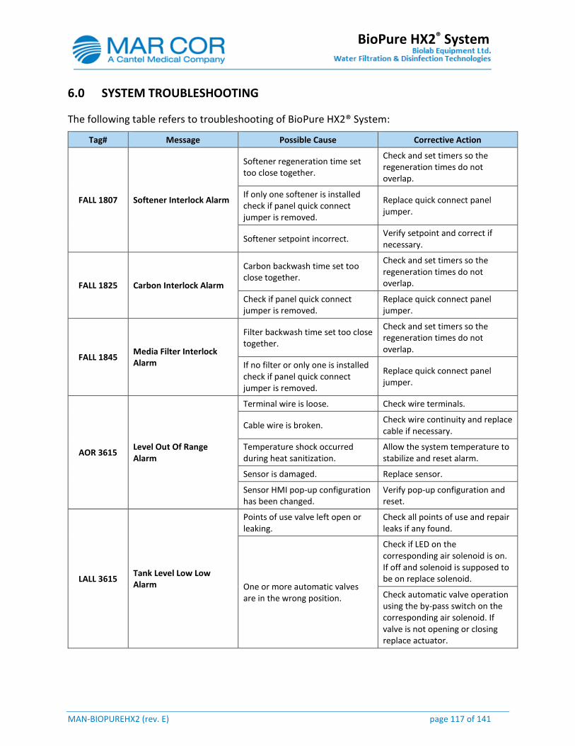
MAN-BIOPUREHX2 (rev. E) page 117 of 141
BioPure HX2® System
6.0 SYSTEM TROUBLESHOOTING
The following table refers to troubleshooting of BioPure HX2® System:
Tag# Message Possible Cause Corrective Action
FALL 1807 Softener Interlock Alarm
Softener regeneration time set too close together.
Check and set timers so the regeneration times do not overlap.
If only one softener is installed check if panel quick connect jumper is removed.
Replace quick connect panel jumper.
Softener setpoint incorrect. Verify setpoint and correct if necessary.
FALL 1825 Carbon Interlock Alarm
Carbon backwash time set too close together.
Check and set timers so the regeneration times do not overlap.
Check if panel quick connect jumper is removed.
Replace quick connect panel jumper.
FALL 1845 Media Filter Interlock Alarm
Filter backwash time set too close together.
Check and set timers so the regeneration times do not overlap.
If no filter or only one is installed check if panel quick connect jumper is removed.
Replace quick connect panel jumper.
AOR 3615 Level Out Of Range Alarm
Terminal wire is loose. Check wire terminals.
Cable wire is broken. Check wire continuity and replace cable if necessary.
Temperature shock occurred during heat sanitization.
Allow the system temperature to stabilize and reset alarm.
Sensor is damaged. Replace sensor.
Sensor HMI pop-up configuration has been changed.
Verify pop-up configuration and reset.
LALL 3615 Tank Level Low Low Alarm
Points of use valve left open or leaking.
Check all points of use and repair leaks if any found.
One or more automatic valves are in the wrong position.
Check if LED on the corresponding air solenoid is on. If off and solenoid is supposed to be on replace solenoid.
Check automatic valve operation using the by-pass switch on the corresponding air solenoid. If valve is not opening or closing replace actuator.
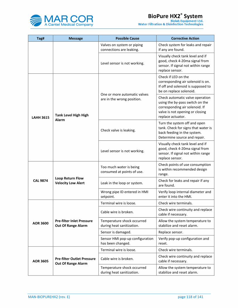
MAN-BIOPUREHX2 (rev. E) page 118 of 141
BioPure HX2® System
Tag# Message Possible Cause Corrective Action
Valves on system or piping connections are leaking.
Check system for leaks and repair if any are found.
Level sensor is not working.
Visually check tank level and if good, check 4-20ma signal from sensor. If signal not within range replace sensor.
LAHH 3615 Tank Level High High Alarm
One or more automatic valves are in the wrong position.
Check if LED on the corresponding air solenoid is on. If off and solenoid is supposed to be on replace solenoid.
Check automatic valve operation using the by-pass switch on the corresponding air solenoid. If valve is not opening or closing replace actuator.
Check valve is leaking.
Turn the system off and open tank. Check for signs that water is back feeding in the system. Determine source and repair.
Level sensor is not working.
Visually check tank level and if good, check 4-20ma signal from sensor. If signal not within range replace sensor.
CAL 9874 Loop Return Flow Velocity Low Alert
Too much water is being consumed at points of use.
Check points of use consumption is within recommended design range.
Leak in the loop or system. Check for leaks and repair if any are found.
Wrong pipe ID entered in HMI setpoint.
Verify loop internal diameter and enter it into the HMI.
AOR 3600 Pre-filter Inlet Pressure Out Of Range Alarm
Terminal wire is loose. Check wire terminals.
Cable wire is broken. Check wire continuity and replace cable if necessary.
Temperature shock occurred during heat sanitization.
Allow the system temperature to stabilize and reset alarm.
Sensor is damaged. Replace sensor.
Sensor HMI pop-up configuration has been changed.
Verify pop-up configuration and reset.
AOR 3605 Pre-filter Outlet Pressure Out Of Range Alarm
Terminal wire is loose. Check wire terminals.
Cable wire is broken. Check wire continuity and replace cable if necessary.
Temperature shock occurred during heat sanitization.
Allow the system temperature to stabilize and reset alarm.
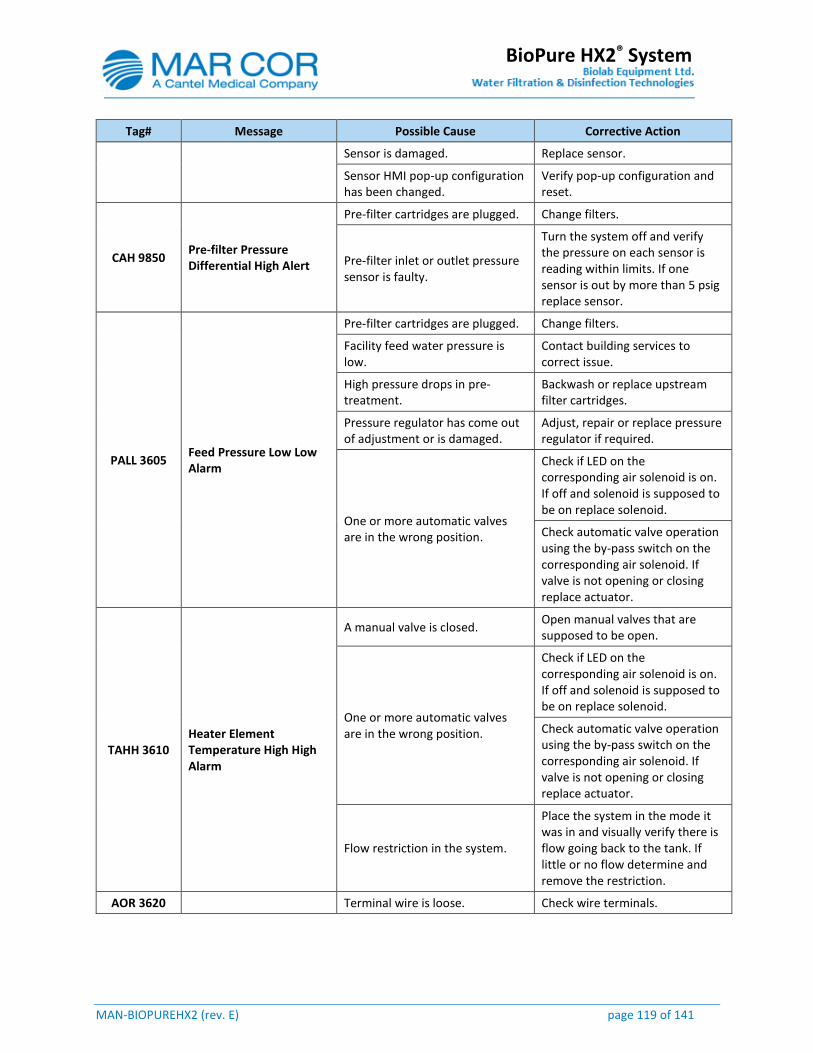
MAN-BIOPUREHX2 (rev. E) page 119 of 141
BioPure HX2® System
Tag# Message Possible Cause Corrective Action
Sensor is damaged. Replace sensor.
Sensor HMI pop-up configuration has been changed.
Verify pop-up configuration and reset.
CAH 9850 Pre-filter Pressure Differential High Alert
Pre-filter cartridges are plugged. Change filters.
Pre-filter inlet or outlet pressure sensor is faulty.
Turn the system off and verify the pressure on each sensor is reading within limits. If one sensor is out by more than 5 psig replace sensor.
PALL 3605 Feed Pressure Low Low Alarm
Pre-filter cartridges are plugged. Change filters.
Facility feed water pressure is low.
Contact building services to correct issue.
High pressure drops in pre-treatment.
Backwash or replace upstream filter cartridges.
Pressure regulator has come out of adjustment or is damaged.
Adjust, repair or replace pressure regulator if required.
One or more automatic valves are in the wrong position.
Check if LED on the corresponding air solenoid is on. If off and solenoid is supposed to be on replace solenoid.
Check automatic valve operation using the by-pass switch on the corresponding air solenoid. If valve is not opening or closing replace actuator.
TAHH 3610 Heater Element Temperature High High Alarm
A manual valve is closed. Open manual valves that are supposed to be open.
One or more automatic valves are in the wrong position.
Check if LED on the corresponding air solenoid is on. If off and solenoid is supposed to be on replace solenoid.
Check automatic valve operation using the by-pass switch on the corresponding air solenoid. If valve is not opening or closing replace actuator.
Flow restriction in the system.
Place the system in the mode it was in and visually verify there is flow going back to the tank. If little or no flow determine and remove the restriction.
AOR 3620 Terminal wire is loose. Check wire terminals.
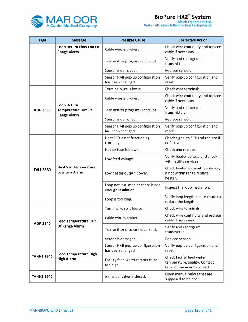
MAN-BIOPUREHX2 (rev. E) page 120 of 141
BioPure HX2® System
Tag# Message Possible Cause Corrective Action
Loop Return Flow Out Of Range Alarm
Cable wire is broken. Check wire continuity and replace cable if necessary.
Transmitter program is corrupt. Verify and reprogram transmitter.
Sensor is damaged. Replace sensor.
Sensor HMI pop-up configuration has been changed.
Verify pop-up configuration and reset.
AOR 3630 Loop Return Temperature Out Of Range Alarm
Terminal wire is loose. Check wire terminals.
Cable wire is broken. Check wire continuity and replace cable if necessary.
Transmitter program is corrupt. Verify and reprogram transmitter.
Sensor is damaged. Replace sensor.
Sensor HMI pop-up configuration has been changed.
Verify pop-up configuration and reset.
TALL 3630 Heat San Temperature Low Low Alarm
Heat SCR is not functioning correctly.
Check signal to SCR and replace if defective.
Heater fuse is blown. Check and replace.
Low feed voltage. Verify heater voltage and check with facility services.
Low heater output power. Check heater element resistance, if not within range replace heater.
Loop not insulated or there is not enough insulation.
Inspect the loop insulation.
Loop is too long. Verify loop length and re-route to reduce the length.
AOR 3640 Feed Temperature Out Of Range Alarm
Terminal wire is loose. Check wire terminals.
Cable wire is broken. Check wire continuity and replace cable if necessary.
Transmitter program is corrupt. Verify and reprogram transmitter.
Sensor is damaged. Replace sensor.
TAHH1 3640 Feed Temperature High High Alarm
Sensor HMI pop-up configuration has been changed.
Verify pop-up configuration and reset.
Facility feed water temperature too high.
Check facility feed water temperature/quality. Contact building services to correct.
TAHH2 3640 A manual valve is closed. Open manual valves that are supposed to be open.
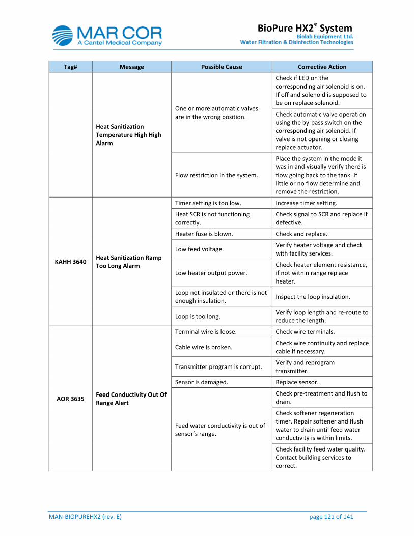
MAN-BIOPUREHX2 (rev. E) page 121 of 141
BioPure HX2® System
Tag# Message Possible Cause Corrective Action
Heat Sanitization Temperature High High Alarm
One or more automatic valves are in the wrong position.
Check if LED on the corresponding air solenoid is on. If off and solenoid is supposed to be on replace solenoid.
Check automatic valve operation using the by-pass switch on the corresponding air solenoid. If valve is not opening or closing replace actuator.
Flow restriction in the system.
Place the system in the mode it was in and visually verify there is flow going back to the tank. If little or no flow determine and remove the restriction.
KAHH 3640 Heat Sanitization Ramp Too Long Alarm
Timer setting is too low. Increase timer setting.
Heat SCR is not functioning correctly.
Check signal to SCR and replace if defective.
Heater fuse is blown. Check and replace.
Low feed voltage. Verify heater voltage and check with facility services.
Low heater output power. Check heater element resistance, if not within range replace heater.
Loop not insulated or there is not enough insulation.
Inspect the loop insulation.
Loop is too long. Verify loop length and re-route to reduce the length.
AOR 3635 Feed Conductivity Out Of Range Alert
Terminal wire is loose. Check wire terminals.
Cable wire is broken. Check wire continuity and replace cable if necessary.
Transmitter program is corrupt. Verify and reprogram transmitter.
Sensor is damaged. Replace sensor.
Feed water conductivity is out of sensor’s range.
Check pre-treatment and flush to drain.
Check softener regeneration timer. Repair softener and flush water to drain until feed water conductivity is within limits.
Check facility feed water quality. Contact building services to correct.
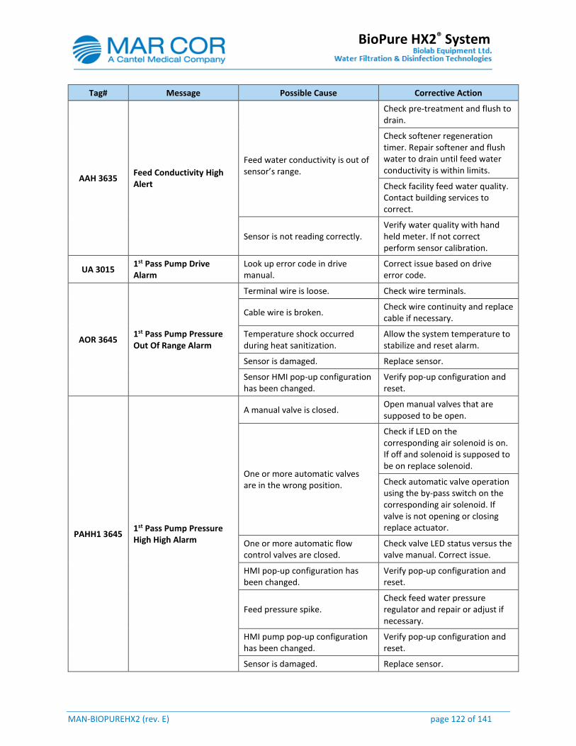
MAN-BIOPUREHX2 (rev. E) page 122 of 141
BioPure HX2® System
Tag# Message Possible Cause Corrective Action
AAH 3635 Feed Conductivity High Alert
Feed water conductivity is out of sensor’s range.
Check pre-treatment and flush to drain.
Check softener regeneration timer. Repair softener and flush water to drain until feed water conductivity is within limits.
Check facility feed water quality. Contact building services to correct.
Sensor is not reading correctly. Verify water quality with hand held meter. If not correct perform sensor calibration.
UA 3015 1st Pass Pump Drive Alarm
Look up error code in drive manual.
Correct issue based on drive error code.
AOR 3645 1st Pass Pump Pressure Out Of Range Alarm
Terminal wire is loose. Check wire terminals.
Cable wire is broken. Check wire continuity and replace cable if necessary.
Temperature shock occurred during heat sanitization.
Allow the system temperature to stabilize and reset alarm.
Sensor is damaged. Replace sensor.
Sensor HMI pop-up configuration has been changed.
Verify pop-up configuration and reset.
PAHH1 3645 1st Pass Pump Pressure High High Alarm
A manual valve is closed. Open manual valves that are supposed to be open.
One or more automatic valves are in the wrong position.
Check if LED on the corresponding air solenoid is on. If off and solenoid is supposed to be on replace solenoid.
Check automatic valve operation using the by-pass switch on the corresponding air solenoid. If valve is not opening or closing replace actuator.
One or more automatic flow control valves are closed.
Check valve LED status versus the valve manual. Correct issue.
HMI pop-up configuration has been changed.
Verify pop-up configuration and reset.
Feed pressure spike. Check feed water pressure regulator and repair or adjust if necessary.
HMI pump pop-up configuration has been changed.
Verify pop-up configuration and reset.
Sensor is damaged. Replace sensor.

MAN-BIOPUREHX2 (rev. E) page 123 of 141
BioPure HX2® System
Tag# Message Possible Cause Corrective Action
PAHH2 3645 1st Pass Heat Sani Pressure High High Alarm
A manual valve is closed. Open manual valves that are supposed to be open.
One or more automatic valves are in the wrong position.
Check if LED on the corresponding air solenoid is on. If off and solenoid is supposed to be on replace solenoid.
Check automatic valve operation using the by-pass switch on the corresponding air solenoid. If valve is not opening or closing replace actuator.
One or more automatic flow control valves are closed.
Check valve LED status versus the valve manual. Correct issue.
HMI valve pop-up configuration has been changed.
Verify pop-up configuration and reset.
Sensor is damaged. Replace sensor.
AOR 3650 1st Pass Reject Pressure Out Of Range Alert
Terminal wire is loose. Check wire terminals.
Cable wire is broken. Check wire continuity and replace cable if necessary.
Temperature shock occurred during heat sanitization.
Allow the system temperature to stabilize and reset alarm.
Sensor is damaged. Replace sensor.
Sensor HMI pop-up configuration has been changed.
Verify pop-up configuration and reset.
AOR 3655 1st Pass Reject Flow Out Of Range Alarm
Terminal wire is loose. Check wire terminals.
Cable wire is broken. Check wire continuity and replace cable if necessary.
Transmitter program is corrupt. Verify and reprogram transmitter.
Sensor is damaged. Replace sensor.
Sensor HMI pop-up configuration has been changed.
Verify pop-up configuration and reset.
AOR 3660 1st Pass Reject Drain Flow Out Of Range Alarm
Terminal wire is loose. Check wire terminals.
Cable wire is broken. Check wire continuity and replace cable if necessary.
Transmitter program is corrupt. Verify and reprogram transmitter.
Sensor is damaged. Replace sensor.
Sensor HMI pop-up configuration has been changed.
Verify pop-up configuration and reset.
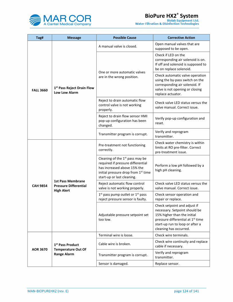
MAN-BIOPUREHX2 (rev. E) page 124 of 141
BioPure HX2® System
Tag# Message Possible Cause Corrective Action
FALL 3660 1st Pass Reject Drain Flow Low Low Alarm
A manual valve is closed. Open manual valves that are supposed to be open.
One or more automatic valves are in the wrong position.
Check if LED on the corresponding air solenoid is on. If off and solenoid is supposed to be on replace solenoid.
Check automatic valve operation using the by-pass switch on the corresponding air solenoid. If valve is not opening or closing replace actuator.
Reject to drain automatic flow control valve is not working properly.
Check valve LED status versus the valve manual. Correct issue.
Reject to drain flow sensor HMI pop-up configuration has been changed.
Verify pop-up configuration and reset.
Transmitter program is corrupt. Verify and reprogram transmitter.
CAH 9854 1st Pass Membrane Pressure Differential High Alert
Pre-treatment not functioning correctly.
Check water chemistry is within limits at RO pre-filter. Correct pre-treatment issue.
Cleaning of the 1st pass may be required if pressure differential has increased above 15% the initial pressure drop from 1st time start-up or last cleaning.
Perform a low pH followed by a high pH cleaning.
Reject automatic flow control valve is not working properly.
Check valve LED status versus the valve manual. Correct issue.
1st pass pump outlet or 1st pass reject pressure sensor is faulty.
Check sensor operation and repair or replace.
Adjustable pressure setpoint set too low.
Check setpoint and adjust if necessary. Setpoint should be 15% higher than the initial pressure differential at 1st time start-up run to loop or after a cleaning has occurred.
AOR 3670 1st Pass Product Temperature Out Of Range Alarm
Terminal wire is loose. Check wire terminals.
Cable wire is broken. Check wire continuity and replace cable if necessary.
Transmitter program is corrupt. Verify and reprogram transmitter.
Sensor is damaged. Replace sensor.
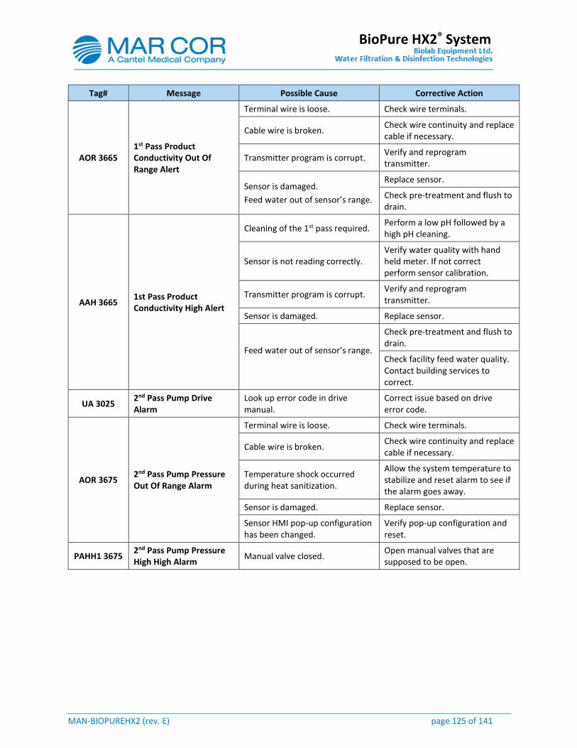
MAN-BIOPUREHX2 (rev. E) page 125 of 141
BioPure HX2® System
Tag# Message Possible Cause Corrective Action
AOR 3665 1st Pass Product Conductivity Out Of Range Alert
Terminal wire is loose. Check wire terminals.
Cable wire is broken. Check wire continuity and replace cable if necessary.
Transmitter program is corrupt. Verify and reprogram transmitter.
Sensor is damaged.
Feed water out of sensor’s range.
Replace sensor.
Check pre-treatment and flush to drain.
AAH 3665 1st Pass Product Conductivity High Alert
Cleaning of the 1st pass required. Perform a low pH followed by a high pH cleaning.
Sensor is not reading correctly. Verify water quality with hand held meter. If not correct perform sensor calibration.
Transmitter program is corrupt. Verify and reprogram transmitter.
Sensor is damaged. Replace sensor.
Feed water out of sensor’s range.
Check pre-treatment and flush to drain.
Check facility feed water quality. Contact building services to correct.
UA 3025 2nd Pass Pump Drive Alarm
Look up error code in drive manual.
Correct issue based on drive error code.
AOR 3675 2nd Pass Pump Pressure Out Of Range Alarm
Terminal wire is loose. Check wire terminals.
Cable wire is broken. Check wire continuity and replace cable if necessary.
Temperature shock occurred during heat sanitization.
Allow the system temperature to stabilize and reset alarm to see if the alarm goes away.
Sensor is damaged. Replace sensor.
Sensor HMI pop-up configuration has been changed.
Verify pop-up configuration and reset.
PAHH1 3675 2nd Pass Pump Pressure High High Alarm
Manual valve closed. Open manual valves that are supposed to be open.
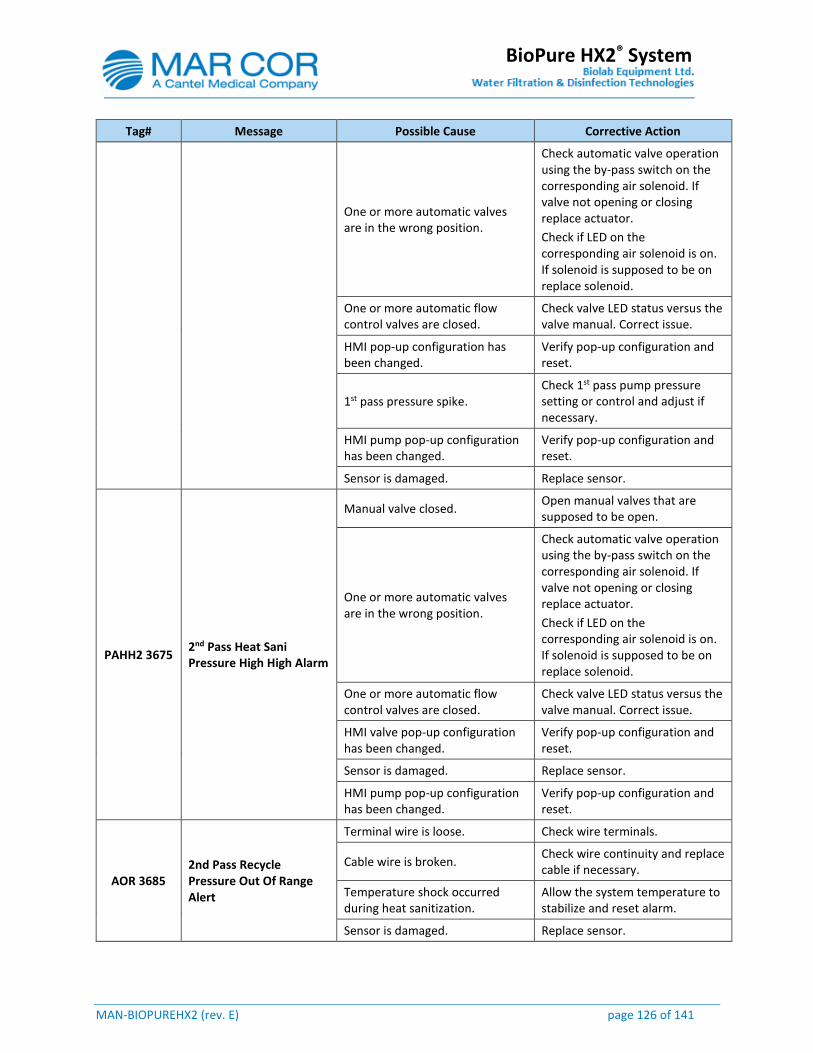
MAN-BIOPUREHX2 (rev. E) page 126 of 141
BioPure HX2® System
Tag# Message Possible Cause Corrective Action
One or more automatic valves are in the wrong position.
Check automatic valve operation using the by-pass switch on the corresponding air solenoid. If valve not opening or closing replace actuator.
Check if LED on the corresponding air solenoid is on. If solenoid is supposed to be on replace solenoid.
One or more automatic flow control valves are closed.
Check valve LED status versus the valve manual. Correct issue.
HMI pop-up configuration has been changed.
Verify pop-up configuration and reset.
1st pass pressure spike. Check 1st pass pump pressure setting or control and adjust if necessary.
HMI pump pop-up configuration has been changed.
Verify pop-up configuration and reset.
Sensor is damaged. Replace sensor.
PAHH2 3675 2nd Pass Heat Sani Pressure High High Alarm
Manual valve closed. Open manual valves that are supposed to be open.
One or more automatic valves are in the wrong position.
Check automatic valve operation using the by-pass switch on the corresponding air solenoid. If valve not opening or closing replace actuator.
Check if LED on the corresponding air solenoid is on. If solenoid is supposed to be on replace solenoid.
One or more automatic flow control valves are closed.
Check valve LED status versus the valve manual. Correct issue.
HMI valve pop-up configuration has been changed.
Verify pop-up configuration and reset.
Sensor is damaged. Replace sensor.
HMI pump pop-up configuration has been changed.
Verify pop-up configuration and reset.
AOR 3685 2nd Pass Recycle Pressure Out Of Range Alert
Terminal wire is loose. Check wire terminals.
Cable wire is broken. Check wire continuity and replace cable if necessary.
Temperature shock occurred during heat sanitization.
Allow the system temperature to stabilize and reset alarm.
Sensor is damaged. Replace sensor.
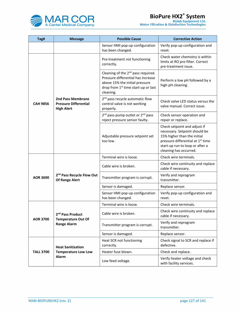
MAN-BIOPUREHX2 (rev. E) page 127 of 141
BioPure HX2® System
Tag# Message Possible Cause Corrective Action
Sensor HMI pop-up configuration has been changed.
Verify pop-up configuration and reset.
CAH 9856 2nd Pass Membrane Pressure Differential High Alert
Pre-treatment not functioning correctly.
Check water chemistry is within limits at RO pre-filter. Correct pre-treatment issue.
Cleaning of the 2nd pass required. Pressure differential has increase above 15% the initial pressure drop from 1st time start-up or last cleaning.
Perform a low pH followed by a high pH cleaning.
2nd pass recycle automatic flow control valve is not working properly.
Check valve LED status versus the valve manual. Correct issue.
2nd pass pump outlet or 2nd pass reject pressure sensor faulty.
Check sensor operation and repair or replace.
Adjustable pressure setpoint set too low.
Check setpoint and adjust if necessary. Setpoint should be 15% higher than the initial pressure differential at 1st time start-up run to loop or after a cleaning has occurred.
AOR 3690 2nd Pass Recycle Flow Out Of Range Alert
Terminal wire is loose. Check wire terminals.
Cable wire is broken. Check wire continuity and replace cable if necessary.
Transmitter program is corrupt. Verify and reprogram transmitter.
Sensor is damaged. Replace sensor.
Sensor HMI pop-up configuration has been changed.
Verify pop-up configuration and reset.
AOR 3700 2nd Pass Product Temperature Out Of Range Alarm
Terminal wire is loose. Check wire terminals.
Cable wire is broken. Check wire continuity and replace cable if necessary.
Transmitter program is corrupt. Verify and reprogram transmitter.
Sensor is damaged. Replace sensor.
TALL 3700 Heat Sanitization Temperature Low Low Alarm
Heat SCR not functioning correctly.
Check signal to SCR and replace if defective.
Heater fuse blown. Check and replace.
Low feed voltage. Verify heater voltage and check with facility services.
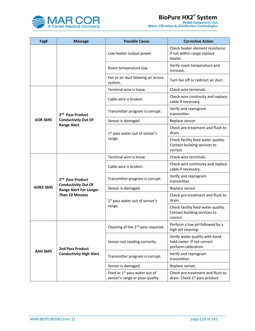
MAN-BIOPUREHX2 (rev. E) page 128 of 141
BioPure HX2® System
Tag# Message Possible Cause Corrective Action
Low heater output power. Check heater element resistance if not within range replace heater.
Room temperature low. Verify room temperature and increase.
Fan or air duct blowing air across system.
Turn fan off or redirect air duct.
AOR 3695 2nd Pass Product Conductivity Out Of Range Alert
Terminal wire is loose. Check wire terminals.
Cable wire is broken. Check wire continuity and replace cable if necessary.
Transmitter program is corrupt. Verify and reprogram transmitter.
Sensor is damaged. Replace sensor.
1st pass water out of sensor’s range.
Check pre-treatment and flush to drain.
Check facility feed water quality. Contact building services to correct.
AOR2 3695
2nd Pass Product Conductivity Out Of Range Alert For Longer Than 10 Minutes
Terminal wire is loose. Check wire terminals.
Cable wire is broken. Check wire continuity and replace cable if necessary.
Transmitter program is corrupt. Verify and reprogram transmitter.
Sensor is damaged. Replace sensor.
1st pass water out of sensor’s range.
Check pre-treatment and flush to drain.
Check facility feed water quality. Contact building services to correct.
AAH 3695 2nd Pass Product Conductivity High Alert
Cleaning of the 2nd pass required. Perform a low pH followed by a high pH cleaning.
Sensor not reading correctly. Verify water quality with hand held meter. If not correct perform calibration.
Transmitter program is corrupt. Verify and reprogram transmitter.
Sensor is damaged. Replace sensor.
Feed or 1st pass water out of sensor’s range or poor quality.
Check pre-treatment and flush to drain. Check 1st pass product.

MAN-BIOPUREHX2 (rev. E) page 129 of 141
BioPure HX2® System
Tag# Message Possible Cause Corrective Action
Check facility feed water or 1st pass quality. Contact building services to correct or perform a low pH followed by a high pH cleaning.
High CO² level in feed water. Check CO² level. Install pH adjust system on feed or degas module on 1st pass product line.
AAHH 3695 2nd Pass Product Conductivity High High Alarm
Cleaning of the 2nd pass required. Perform a low pH followed by a high pH cleaning.
Sensor not reading correctly. Verify water quality with hand held meter. If not correct perform calibration.
Transmitter program is corrupt. Verify and reprogram transmitter.
Sensor is damaged. Replace sensor.
Feed or 1st pass water out of sensor’s range or poor quality.
Check pre-treatment and flush to drain. Check 1st pass product
Check facility feed water or 1st pass quality. Contact building services to correct or perform a low pH followed by a high pH cleaning.
High CO² level in feed water. Check CO² level. Install pH adjust system on feed or degas module on 1st pass product line.
AAHH2 3695
2nd Pass Product Conductivity High High Alarm For Longer Than 10 Minutes While Running To Drain
Cleaning of the 2nd pass required. Perform a low pH followed by a high pH cleaning.
Sensor not reading correctly. Verify water quality with hand held meter. If not correct perform calibration.
Transmitter program is corrupt. Verify and reprogram transmitter.
Sensor is damaged. Replace sensor.
Feed or 1st pass water out of sensor’s range or poor quality.
Check pre-treatment and flush to drain. Check 1st pass product
Check facility feed water or 1st pass quality. Contact building services to correct or perform a low pH followed by a high pH cleaning.

MAN-BIOPUREHX2 (rev. E) page 130 of 141
BioPure HX2® System
Tag# Message Possible Cause Corrective Action
High CO² level in feed water. Check CO² level. Install pH adjust system on feed or degas module on 1st pass product line.
AOR 3705 2nd Pass Product Pressure Out Of Range Alarm
Terminal wire is loose. Check wire terminals.
Cable wire is broken. Check wire continuity and replace cable if necessary.
Temperature shock occurred during heat sanitization.
Allow the system temperature to stabilize and reset alarm to see if the alarm goes away.
Sensor is damaged. Replace sensor.
Sensor HMI pop-up configuration has been changed.
Verify pop-up configuration and reset.
PAHH 3705 2nd Pass Product Pressure High High Alarm
A manual valve is closed. Open manual valves that are supposed to be open.
One or more automatic valves are in the wrong position.
Check if LED on the corresponding air solenoid is on. If off and solenoid is supposed to be on replace solenoid.
Check automatic valve operation using the by-pass switch on the corresponding air solenoid. If valve is not opening or closing replace actuator.
Product flow is too high for the loop inside diameter and or length.
Calculate loop pressure drop (including elbows, tees and elevation). If close to setpoint a large diameter loop will need to be installed or re-roughed to reduce the length.
Feed water pressure too high. Check feed water pressure and adjust, repair or replace regulator.
HMI pop-up configuration has been changed.
Verify pop-up configuration and reset.
Factory product flow setting too high.
Verify flow what flow rate was specified and change settings.
2nd pass pressure spike. Check 2nd pass pump pressure setting or control and adjust if necessary.
HMI pump pop-up configuration has been changed.
Verify pop-up configuration and reset.
Sensor reading incorrectly on HMI.
Verify sensor operation and change or calibrate if required.
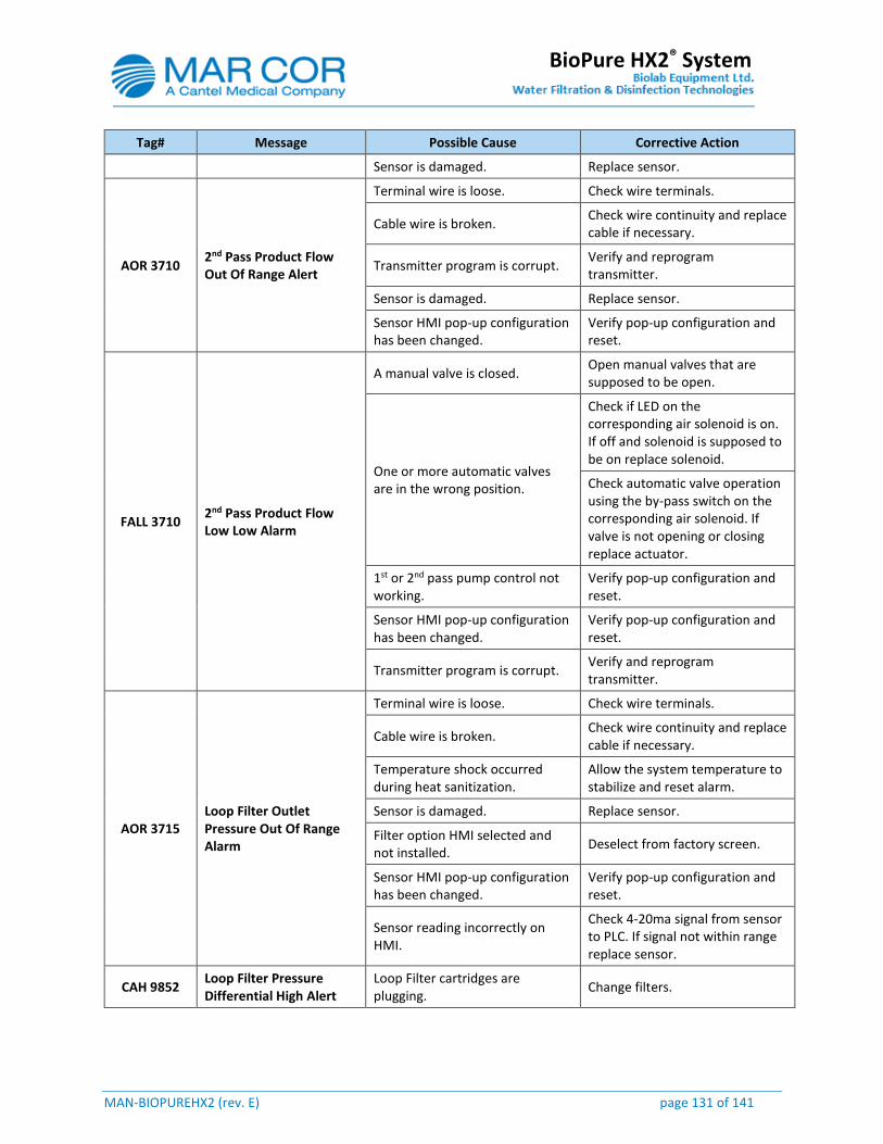
MAN-BIOPUREHX2 (rev. E) page 131 of 141
BioPure HX2® System
Tag# Message Possible Cause Corrective Action
Sensor is damaged. Replace sensor.
AOR 3710 2nd Pass Product Flow Out Of Range Alert
Terminal wire is loose. Check wire terminals.
Cable wire is broken. Check wire continuity and replace cable if necessary.
Transmitter program is corrupt. Verify and reprogram transmitter.
Sensor is damaged. Replace sensor.
Sensor HMI pop-up configuration has been changed.
Verify pop-up configuration and reset.
FALL 3710 2nd Pass Product Flow Low Low Alarm
A manual valve is closed. Open manual valves that are supposed to be open.
One or more automatic valves are in the wrong position.
Check if LED on the corresponding air solenoid is on. If off and solenoid is supposed to be on replace solenoid.
Check automatic valve operation using the by-pass switch on the corresponding air solenoid. If valve is not opening or closing replace actuator.
1st or 2nd pass pump control not working.
Verify pop-up configuration and reset.
Sensor HMI pop-up configuration has been changed.
Verify pop-up configuration and reset.
Transmitter program is corrupt. Verify and reprogram transmitter.
AOR 3715 Loop Filter Outlet Pressure Out Of Range Alarm
Terminal wire is loose. Check wire terminals.
Cable wire is broken. Check wire continuity and replace cable if necessary.
Temperature shock occurred during heat sanitization.
Allow the system temperature to stabilize and reset alarm.
Sensor is damaged. Replace sensor.
Filter option HMI selected and not installed.
Deselect from factory screen.
Sensor HMI pop-up configuration has been changed.
Verify pop-up configuration and reset.
Sensor reading incorrectly on HMI.
Check 4-20ma signal from sensor to PLC. If signal not within range replace sensor.
CAH 9852 Loop Filter Pressure Differential High Alert
Loop Filter cartridges are plugging.
Change filters.

MAN-BIOPUREHX2 (rev. E) page 132 of 141
BioPure HX2® System
Tag# Message Possible Cause Corrective Action
Filter inlet or outlet pressure sensor faulty.
Verify sensor operation and change or calibrate if required.
Filter option HMI selected and not installed.
Deselect from factory screen.
AOR 6640 Compressed Air Pressure Out Of Range Alarm
Terminal wire is loose. Check wire terminals.
Cable wire is broken. Check wire continuity and replace cable if necessary.
Sensor is damaged. Replace sensor.
Sensor HMI pop-up configuration has been changed.
Verify pop-up configuration and reset.
Sensor reading incorrectly on HMI.
Replace sensor.
PAL 6640 Compressed Air Pressure Low Alert
Air leak. Check for leaks and repair.
Compressor tank is full of water. Purge compressor tank.
Compressor outlet filter is plugged.
Check filter and replace.
Compressor outlet filter is full of water.
Purge compressor filter.
Compressor oil is low. Check oil level and fill if necessary.
PALL1 6440 Compressed Air Pressure Low Low Alarm
Air leak. Check for leaks and repair.
Compressor tank is full of water. Purge compressor tank.
Compressor outlet filter is plugged.
Check filter and replace.
Compressor outlet filter is full of water.
Purge compressor filter.
Compressor oil is low. Check oil level and fill if necessary.
PALL2 6440 Compressed Air Pressure Low Low Alarm
Air leak. Check for leaks and repair.
Compressor tank is full of water. Purge compressor tank.
Compressor outlet filter is plugged.
Check filter and replace.
Compressor outlet filter is full of water.
Purge compressor filter.
Compressor oil is low. Check oil level and fill if necessary.
Fuse blown. Check and replace if necessary.
Compressor pressure start /stop switch faulty.
Check switch and replace if faulty.
Compressor faulty. Check and replace if faulty.

MAN-BIOPUREHX2 (rev. E) page 133 of 141
BioPure HX2® System
Tag# Message Possible Cause Corrective Action
CAL 9864 System Percent Rejection Low Alert
2nd pass product water conductivity high.
Verify 2nd pass product water. Perform a low pH followed by a high pH cleaning.
Adjustable setpoint set too high. Adjust setpoint to lower setting.
EAL 9800 Main Power Failure Alarm
Main disconnect fuses are blown. Check fuse and replace.
No power is going to panel main disconnect.
Check voltage at the main disconnect. If no voltage is detected contact facility services.
Facility power outage. Wait for power to be restored.
YSA 9805 Emergency Stop Alarm
Main panel red push button is pressed.
Consult with facility employees to verify who pushed the button. Reset the push button only if no emergency situation exists.
Remotely wired red push button is pressed.
Consult with facility employees to verify who pushed the button. Reset the push button only if no emergency situation exists.
UA 9980 DI Alarm
DI tank is below quality setpoint. Replace DI tank(s).
If no DI used check if panel quick connect jumper is removed.
Replace quick connect panel jumper.
UA 9985 DI Active Alarm
DI back up panel switch turned on.
Consult with facility employees why the switch is enabled. If DI back up is not required turn switch off.
If no DI used check if panel quick connect jumper is removed.
Replace quick connect panel jumper.
UA 9957 Water Leak Alarm
Water leak detector in alarm. Verify if a water leak is active and fix leaks.
If no leak detector installed check if panel quick connect jumper is removed.
Replace quick connect panel jumper.
UA 9990 Auxiliary Alarm
Auxiliary device is in alarm. Verify if device is in alarm and correct issue.
If no auxiliary device installed check if panel quick connect jumper is removed.
Replace quick connect panel jumper.
PLC Battery Alarm Battery is low. Replace battery.
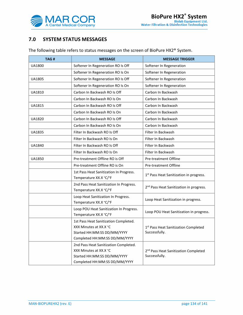
MAN-BIOPUREHX2 (rev. E) page 134 of 141
BioPure HX2® System
7.0 SYSTEM STATUS MESSAGES
The following table refers to status messages on the screen of BioPure HX2® System.
TAG # MESSAGE MESSAGE TRIGGER
UA1800 Softener In Regeneration RO Is Off Softener In Regeneration
Softener In Regeneration RO Is On Softener In Regeneration
UA1805 Softener In Regeneration RO Is Off Softener In Regeneration
Softener In Regeneration RO Is On Softener In Regeneration
UA1810 Carbon In Backwash RO Is Off Carbon In Backwash
Carbon In Backwash RO Is On Carbon In Backwash
UA1815 Carbon In Backwash RO Is Off Carbon In Backwash
Carbon In Backwash RO Is On Carbon In Backwash
UA1820 Carbon In Backwash RO Is Off Carbon In Backwash
Carbon In Backwash RO Is On Carbon In Backwash
UA1835 Filter In Backwash RO Is Off Filter In Backwash
Filter In Backwash RO Is On Filter In Backwash
UA1840 Filter In Backwash RO Is Off Filter In Backwash
Filter In Backwash RO Is On Filter In Backwash
UA1850 Pre-treatment Offline RO is Off Pre-treatment Offline
Pre-treatment Offline RO is On Pre-treatment Offline
1st Pass Heat Sanitization In Progress.
Temperature XX.X °C/°F 1st Pass Heat Sanitization in progress.
2nd Pass Heat Sanitization In Progress.
Temperature XX.X °C/°F 2nd Pass Heat Sanitization in progress.
Loop Heat Sanitization In Progress.
Temperature XX.X °C/°F Loop Heat Sanitization in progress.
Loop POU Heat Sanitization In Progress.
Temperature XX.X °C/°F Loop POU Heat Sanitization in progress.
1st Pass Heat Sanitization Completed.
XXX Minutes at XX.X °C
Started HH:MM:SS DD/MM/YYYY
Completed HH:MM:SS DD/MM/YYYY
1st Pass Heat Sanitization Completed Successfully.
2nd Pass Heat Sanitization Completed.
XXX Minutes at XX.X °C
Started HH:MM:SS DD/MM/YYYY
Completed HH:MM:SS DD/MM/YYYY
2nd Pass Heat Sanitization Completed Successfully.
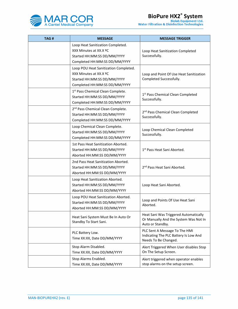
MAN-BIOPUREHX2 (rev. E) page 135 of 141
BioPure HX2® System
TAG # MESSAGE MESSAGE TRIGGER
Loop Heat Sanitization Completed.
XXX Minutes at XX.X ºC
Started HH:MM:SS DD/MM/YYYY
Completed HH:MM:SS DD/MM/YYYY
Loop Heat Sanitization Completed Successfully.
Loop POU Heat Sanitization Completed.
XXX Minutes at XX.X ºC
Started HH:MM:SS DD/MM/YYYY
Completed HH:MM:SS DD/MM/YYYY
Loop and Point Of Use Heat Sanitization Completed Successfully.
1st Pass Chemical Clean Complete.
Started HH:MM:SS DD/MM/YYYY
Completed HH:MM:SS DD/MM/YYYY
1st Pass Chemical Clean Completed Successfully.
2nd Pass Chemical Clean Complete.
Started HH:MM:SS DD/MM/YYYY
Completed HH:MM:SS DD/MM/YYYY
2nd Pass Chemical Clean Completed Successfully.
Loop Chemical Clean Complete.
Started HH:MM:SS DD/MM/YYYY
Completed HH:MM:SS DD/MM/YYYY
Loop Chemical Clean Completed Successfully.
1st Pass Heat Sanitization Aborted.
Started HH:MM:SS DD/MM/YYYY
Aborted HH:MM:SS DD/MM/YYYY
1st Pass Heat Sani Aborted.
2nd Pass Heat Sanitization Aborted.
Started HH:MM:SS DD/MM/YYYY
Aborted HH:MM:SS DD/MM/YYYY
2nd Pass Heat Sani Aborted.
Loop Heat Sanitization Aborted.
Started HH:MM:SS DD/MM/YYYY
Aborted HH:MM:SS DD/MM/YYYY
Loop Heat Sani Aborted.
Loop POU Heat Sanitization Aborted.
Started HH:MM:SS DD/MM/YYYY
Aborted HH:MM:SS DD/MM/YYYY
Loop and Points Of Use Heat Sani Aborted.
Heat Sani System Must Be In Auto Or Standby To Start Sani.
Heat Sani Was Triggered Automatically Or Manually And the System Was Not In Auto or Standby.
PLC Battery Low.
Time XX:XX, Date DD/MM/YYYY
PLC Sent A Message To The HMI Indicating The PLC Battery Is Low And Needs To Be Changed.
Stop Alarm Disabled.
Time XX:XX, Date DD/MM/YYYY
Alert Triggered When User disables Stop On The Setup Screen.
Stop Alarms Enabled.
Time XX:XX, Date DD/MM/YYYY
Alert triggered when operator enables stop alarms on the setup screen.

MAN-BIOPUREHX2 (rev. E) page 136 of 141
BioPure HX2® System
TAG # MESSAGE MESSAGE TRIGGER
Heat Sani Paused Due To Pre-treatment Regeneration or Backwash.
Time XX:XX, Date DD/MM/YYYY
A Pre-treatment Device Is In Regeneration Or Backwash. The Heat Sani Has Paused Until The Device Is Finished It’s Cycle.
Scheduled Heat Sani Could Not Be Completed.
Heat Sani Could Not Be Completed Due To An Alarm Or User Interruption.
DST MANUAL PLUS ONE HOUR
User presses the “+ Plus 1 hour” push button on the HMI “Time and Date” screen.
DST MANUAL MINUS ONE HOUR
User presses the “- Minus 1 hour” push button on the HMI “Time and Date” screen.
DST AUTO PLUS ONE HOUR
The time is automatically changed if the “Automatic Daylight Savings time Enabled” is set to yes, and the current time is greater than the “Set DST Spring (+ Plus 1 hour) and less than “Set DST Fall (- Minus 1 hour).
DST AUTO MINUS ONE HOUR
The time is automatically changed if the “Automatic Daylight Savings time Enabled” is set to yes, and the current time is less than the “Set DST Spring (+ Plus 1 hour) or greater than “Set DST Fall (- Minus 1 hour).
WATER SAMPLE REQUIRED
15 minutes after entering modes 8, 11 or 13 and setpoint is enabled.
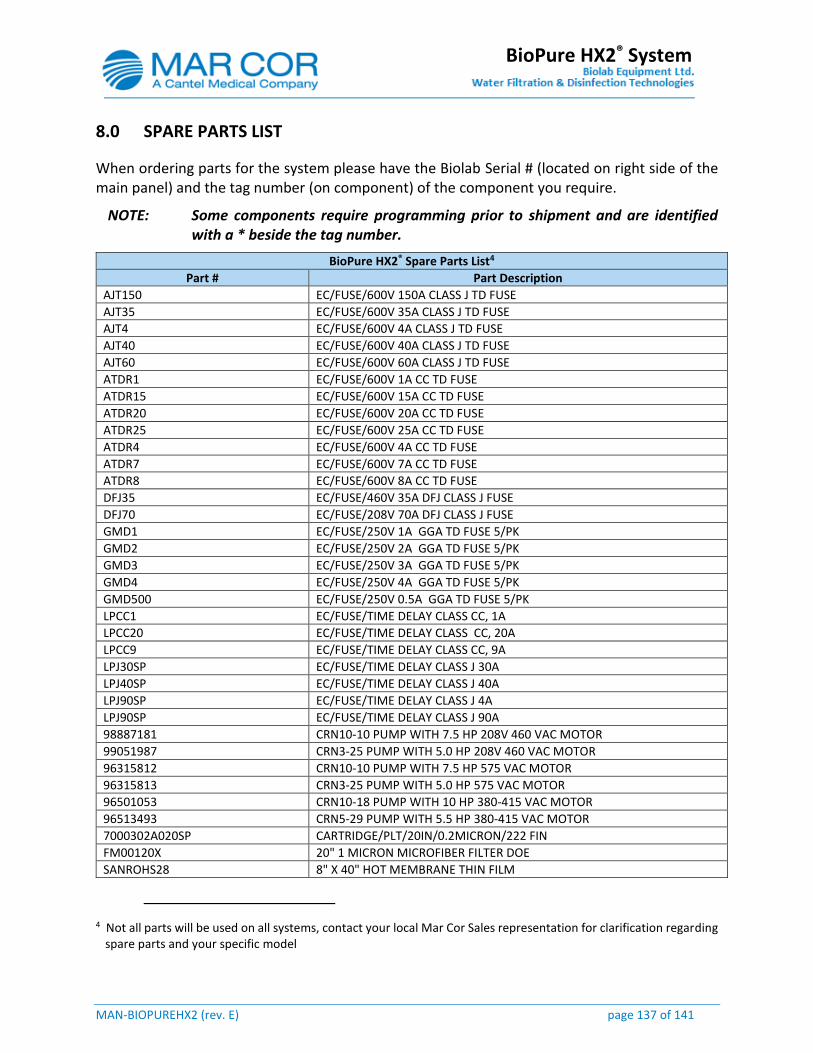
MAN-BIOPUREHX2 (rev. E) page 137 of 141
BioPure HX2® System
8.0 SPARE PARTS LIST
When ordering parts for the system please have the Biolab Serial # (located on right side of the main panel) and the tag number (on component) of the component you require.
NOTE: Some components require programming prior to shipment and are identified with a * beside the tag number.
BioPure HX2® Spare Parts List4
Part # Part Description
AJT150 EC/FUSE/600V 150A CLASS J TD FUSE
AJT35 EC/FUSE/600V 35A CLASS J TD FUSE
AJT4 EC/FUSE/600V 4A CLASS J TD FUSE
AJT40 EC/FUSE/600V 40A CLASS J TD FUSE
AJT60 EC/FUSE/600V 60A CLASS J TD FUSE
ATDR1 EC/FUSE/600V 1A CC TD FUSE
ATDR15 EC/FUSE/600V 15A CC TD FUSE
ATDR20 EC/FUSE/600V 20A CC TD FUSE
ATDR25 EC/FUSE/600V 25A CC TD FUSE
ATDR4 EC/FUSE/600V 4A CC TD FUSE
ATDR7 EC/FUSE/600V 7A CC TD FUSE
ATDR8 EC/FUSE/600V 8A CC TD FUSE
DFJ35 EC/FUSE/460V 35A DFJ CLASS J FUSE
DFJ70 EC/FUSE/208V 70A DFJ CLASS J FUSE
GMD1 EC/FUSE/250V 1A GGA TD FUSE 5/PK
GMD2 EC/FUSE/250V 2A GGA TD FUSE 5/PK
GMD3 EC/FUSE/250V 3A GGA TD FUSE 5/PK
GMD4 EC/FUSE/250V 4A GGA TD FUSE 5/PK
GMD500 EC/FUSE/250V 0.5A GGA TD FUSE 5/PK
LPCC1 EC/FUSE/TIME DELAY CLASS CC, 1A
LPCC20 EC/FUSE/TIME DELAY CLASS CC, 20A
LPCC9 EC/FUSE/TIME DELAY CLASS CC, 9A
LPJ30SP EC/FUSE/TIME DELAY CLASS J 30A
LPJ40SP EC/FUSE/TIME DELAY CLASS J 40A
LPJ90SP EC/FUSE/TIME DELAY CLASS J 4A
LPJ90SP EC/FUSE/TIME DELAY CLASS J 90A
98887181 CRN10-10 PUMP WITH 7.5 HP 208V 460 VAC MOTOR
99051987 CRN3-25 PUMP WITH 5.0 HP 208V 460 VAC MOTOR
96315812 CRN10-10 PUMP WITH 7.5 HP 575 VAC MOTOR
96315813 CRN3-25 PUMP WITH 5.0 HP 575 VAC MOTOR
96501053 CRN10-18 PUMP WITH 10 HP 380-415 VAC MOTOR
96513493 CRN5-29 PUMP WITH 5.5 HP 380-415 VAC MOTOR
7000302A020SP CARTRIDGE/PLT/20IN/0.2MICRON/222 FIN
FM00120X 20" 1 MICRON MICROFIBER FILTER DOE
SANROHS28 8" X 40" HOT MEMBRANE THIN FILM
4 Not all parts will be used on all systems, contact your local Mar Cor Sales representation for clarification regarding spare parts and your specific model
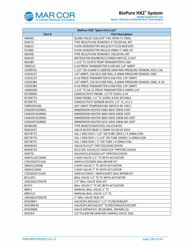
MAN-BIOPUREHX2 (rev. E) page 138 of 141
BioPure HX2® System
BioPure HX2® Spare Parts List4
Part # Part Description
466040 GLOBE VALVE 316L/3/4" FAIL OPEN TC ENDS
556575 TYPE 8012/FLOW SENSOR/1.5”/SS/20 RA, MT
556613 FLOW SENSOR/TYPE 8012/3/4"TC/SS BODY/EP
557065 FLOW SENSOR/TYPE 8012/4-20MA 1" AND UP
560766 TYPE 8012/FLOW SENSOR/1”/SS/20 RA, MT
563419 METER/CON,RES/8619/3 CONDO INPUTS, 2 OUT
992180 1-1/2" TC SS RTD TEMP TRANSMITTER 0-200
7093122 S-10 PRESS TRANSMITTER 0-100 WC 1/4" MNPT
13299701 1 1/2" TRI-CLAMP 0-100PSIG SANITARY PRESSURE TRANSM, M12, CAL
13333127 1/4" MNPT, 316 SS 0-100 PSIG, 4-20MA PRESSURE SENSOR, 100C
13333127 A-10 PRESS TRANSMITTER 0-100 PSIG 1/4" MNPT
13335384 1/4" MNPT, 316 SS 0-500 PSIG, 4-20MA PRESSURE SENSOR, 100C, A-10
13335384 A-10 PRESS TRANSMITTER 0-500 PSIG 1/4" MNPT
14020300 1-1/2" TC SA-11 PRESS TRANSMITTER 0-100PSI 1/4"
92709095 CONDUCTIVITY PROBE, 1.5"TC 316SS, 0.1K
92709773 COND PROBE, 1.5" TC 316SS, 0.01K 20'CABLE
92709775 CONDUCTIVITY SENSOR W/ATC 1.5" TC, K=1 C
TWR5202100 3/4" MNPT TEMPERATURE SWITCH NC 100 C
CXS620F332R001 IMMERSION HEATER 208V 60HZ 20KW CERT
CXS620F332R002 IMMERSION HEATER 460V 60HZ 20KW CERT
CXS620F332R005 IMMERSION HEATER 380V 50HZ 20KW NO CERT
CXS620F332R007 IMMERSION HEATER 415V 50HZ 20KW NO CERT
00186260 TYPE 8640/3/2WAY/SOL VALV/24VDC
00241627 VALVE BLOCK 8640 11 BANK 10 VALVE 6524
00278773 VAL / ANG SEAT / 1/2" OD TUBE /DN15 / 4-20MA CON
00278774 VAL / ANG SEAT / 1-1/2" OD TUBE /DN40 / 4-20MA CON
00278775 VAL / ANG SEAT / 1" OD TUBE / 4-20MA CON
00456443 VALVE/SV/1/2” FNPT/6213/NC/24VDC
00458732 6213 SOL VALVE/2/2 WAY/1/4" FNPT/NC/24VAC
458776 VALVE/6213/316SS/1/4" FPNT/NC/24VDC
3WAY112CCWSR 3 WAY VALVE 1.5” TC WITH ACTUATOR
1701502271154J 3WAY112CCWSR SEAL REPAIR KIT
3WAY1CCWSR 3 WAY VALVE 1” TC WITH ACTUATOR
3WAY1CWSR 3 WAY VALVE 1“ TC WITH ACTUATOR
1701002271154J 3WAY1CCWSR / 3WAY1CWST SEAL REPAIR KIT
BV112FC BALL VALVE 1.5” TC FC WITH ACTUATOR
14015022703578 1.5” BALL VALVE SEAL KIT
BV1FC BALL VALVE 1” TC NC WITH ACTUATOR
MBV1 MANUAL BALL VALVE 1” TC
MBV112 MANUAL BALL VALVE 1.5” TC
14010022703578 1” BALL VALVE SEAL KIT
OFSV90F1 VALVE/PV,90/316/1”-1.5" TC/90/25RA/EP
OFSV90F34 VALVE/PV,90/316/3/4” TC/90/25RA/EP/COC/MT
OFSV90RK VALVE REPAIR KIT, 90 DEGREE, REPAIRS (2)
OFSVILF 1/2"TCx3/8"HB SANITARY SAMPLE VALVE 316L
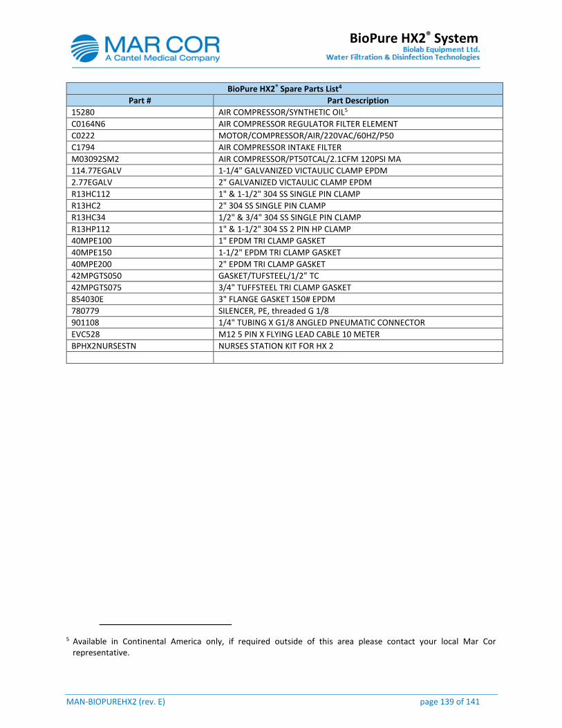
MAN-BIOPUREHX2 (rev. E) page 139 of 141
BioPure HX2® System
BioPure HX2® Spare Parts List4
Part # Part Description
15280 AIR COMPRESSOR/SYNTHETIC OIL5
C0164N6 AIR COMPRESSOR REGULATOR FILTER ELEMENT
C0222 MOTOR/COMPRESSOR/AIR/220VAC/60HZ/P50
C1794 AIR COMPRESSOR INTAKE FILTER
M03092SM2 AIR COMPRESSOR/PT50TCAL/2.1CFM 120PSI MA
114.77EGALV 1-1/4" GALVANIZED VICTAULIC CLAMP EPDM
2.77EGALV 2" GALVANIZED VICTAULIC CLAMP EPDM
R13HC112 1" & 1-1/2" 304 SS SINGLE PIN CLAMP
R13HC2 2" 304 SS SINGLE PIN CLAMP
R13HC34 1/2" & 3/4" 304 SS SINGLE PIN CLAMP
R13HP112 1" & 1-1/2" 304 SS 2 PIN HP CLAMP
40MPE100 1" EPDM TRI CLAMP GASKET
40MPE150 1-1/2" EPDM TRI CLAMP GASKET
40MPE200 2" EPDM TRI CLAMP GASKET
42MPGTS050 GASKET/TUFSTEEL/1/2” TC
42MPGTS075 3/4" TUFFSTEEL TRI CLAMP GASKET
854030E 3" FLANGE GASKET 150# EPDM
780779 SILENCER, PE, threaded G 1/8
901108 1/4" TUBING X G1/8 ANGLED PNEUMATIC CONNECTOR
EVC528 M12 5 PIN X FLYING LEAD CABLE 10 METER
BPHX2NURSESTN NURSES STATION KIT FOR HX 2
5 Available in Continental America only, if required outside of this area please contact your local Mar Cor representative.

MAN-BIOPUREHX2 (rev. E) page 140 of 141
BioPure HX2® System
9.0 GENERAL LIMITED WARRANTY
Mar Cor Purification and Biolab Equipment Ltd. (“Mar Cor®”) warrants all products manufactured by Mar Cor® to be free from defects in material and workmanship under normal use for a period of one year from date of shipment. Warranty is only provided when the equipment is properly maintained in accordance with Mar Cor® instructions. Our obligation shall be limited to the repair or replacement at our option of any parts we deem defective. Consequential damages due to the failure of any part or system are not provided. Mar Cor® provides no other warranty, expressed or implied. There is no warranty of merchantability or fitness for a particular purpose. Other manufacturer’s equipment offered, as part of any proposal shall carry the manufacturer’s warranty. On site, labour is covered for the first 90 days. Travel time and expenses are not covered.
CONTACT INFORMATION
For further information regarding the operation or maintenance of the Mar Cor® water system and for ordering, please contact your local Mar Cor Purification office. When ordering replacement parts, please provide the Biolab Serial # located on the right side of the control panel.
CANADA
Manufactured by: Biolab Equipment Ltd o/a Mar Cor Purification. 3250 Harvester Rd - Unit 6 Burlington, ON L7N 3W9 Tel: (905) 639-7025 Toll Free: (800) 268-5035 Fax: (905) 639-0425
UNITED STATES OF AMERICA
Distributed By: Mar Cor Purification 4450 Township Line Rd Skippack, PA 19474-1429 Tel: (484) 991-0220 Toll Free: (800) 346-0365 Fax: (484) 991-0230 [email protected]
WORLD WIDE WEB
www.mcpur.com

MAN-BIOPUREHX2 (rev. E) page 141 of 141
BioPure HX2® System
This Page Has Intentionally Been Left Blank


![mpr tender schedule 124 new e - cr.indianrailways.gov.in · as per IS 737/1986 or latest GRADE 40800 conditional Hx2 [Nature of Item - Non Safety] CWM(S&T) WS BYCULLA 4300.000Kgs.WITHIN](https://img.pdfslide.net/doc/110x75/5e937f4fac05644afd3c5558/mpr-tender-schedule-124-new-e-cr-as-per-is-7371986-or-latest-grade-40800-conditional.jpg)