Embed Size (px)
Citation preview
Informador Técnico 85(2) Julio - Diciembre 2021: 146 - 159 e-ISSN 2256-5035 http://doi.org/10.23850/22565035.3363
146
IoT high-frequency electronic transformer with dimmable output
voltage using PWM signalsTransformador electrónico de alta frecuencia IoT con voltaje de
salida regulable mediante señales PWM
Received: 23-11-2020 Accepted: 22-06-2021
How to quote: Trillo-León, Nelson; Barrero-Pérez, Jaime; Jaimes-Flórez, Julián; Rojas, David (2021) IoT high-frequency electronic transformer with dimmable output voltage using PWM signals. Informador Técnico, 85(2), 146 -159. https://doi.org/10.23850/22565035.3363
AbstractThis work presents the design, simulation, and implementation of a low-power electronic transformer, which output effective voltage can be controlled wirelessly through WIFI, via a user interface on a mobile phone. The methodology used in this project consists of 4 stages, a rectifier, an inverter, the inverter’s control system, and a ferrite reducer. The inverter has a full-bridge design and was implemented using MOSFET. The control system can vary the frequency and duty cycle of the output signals, by phase shifting the control signals, thus achieving the functionality of reducing the effective output voltage. Circuit design simulations were performed using PsPice Orcad. The implementation and the mathematical model of the built electronic transformer are carried out. The designed transformer operates with a maximum input voltage of 120 Vrms at 60 Hz at frequencies between 20 kHz and 30 kHz, which are controlled through the user interface; can reduce a 120 Vrms 60 Hz input signal to an effective voltage between 10 Vrms and 20 Vrms at a maximum power of 50 W. This project presents the feasibility of developing electronic transformers with variable output voltage, remotely controlled using IoT technology.
Keywords: control system; electronic transformer; full-bridge inverter; PWM; rectifier; remote control.
ResumenEste trabajo presenta el diseño, simulación e implementación de un transformador electrónico de baja potencia, cuya salida de voltaje efectivo se puede controlar de forma inalámbrica a través de WIFI, por medio de una interfaz de usuario en un teléfono móvil. La metodología usada en este proyecto está conformada por 4 etapas, un rectificador, un inversor, un sistema de control de los inversores y un reductor de ferrita. El inversor tiene un diseño de puente completo y se implementó utilizando MOSFET. El sistema de control puede variar la
1 Universidad Industrial de Santander (Colombia). Email: [email protected]: https://orcid.org/0000-0002-9292-2461
2 Universidad Industrial de Santander (Colombia). Email: [email protected]: https://orcid.org/0000-0003-2443-8608
3 Universidad Industrial de Santander (Colombia). Email: [email protected]: https://orcid.org/0000-0003-3328-5180
4 Universidad Industrial de Santander (Colombia). Email: [email protected]: https://orcid.org/0000-0002-1662-3822
Nelson Trillos-León1
Jaime Barrero-Pérez2
Julián Jaimes-Flórez3
David Rojas4
Informador Técnico 85(2) Julio - Diciembre 2021: 146 - 159
147
frecuencia y el ciclo de trabajo de las señales a la salida, cambiando de fase las señales de control, logrando así la funcionalidad de reducir el voltaje eficaz de salida. Se realizaron simulaciones del diseño circuital utilizando PsPice Orcad. Se realizó la implementación y el modelo matemático del transformador electrónico construido. El transformador diseñado opera con voltaje de entrada máximo de 120 Vrms a 60 Hz a frecuencias entre 20 kHz y 30 kHz, las cuales son controladas a través de la interfaz de usuario; puede reducir una señal de entrada de 120 Vrms 60 Hz a un voltaje eficaz entre 10 Vrms y 20 Vrms a una potencia máxima de 50 W. Este proyecto presenta la viabilidad de desarrollar transformadores electrónicos con voltaje de salida variable, controlados de forma remota por medio de tecnología IoT.
Palabras clave: control remoto; inversor de puente complete; PWM; rectificador; sistema de control; transformador electrónico.
1. IntroductionThe electronic transformers convert voltage levels to another, depending on the spiral winding’s ratio, components, circuit topology, and design. Principally, an electronic transformer is made for two insolated coils that are winding in a core of ferromagnetic material. Once an alternating current (AC) is applied to one of the coils, this induces current into the secondary coil. In transformer design theory, the operation frequency of a transformer is inversely proportional to its size and weight, better explained by Keke and Lin (2014), which means that if the electronic transformers work to high frequency, the size and weight are reduced (Battal; Balci; Sefa, 2021). This property of transformers is quite desirable and is being expanded in many different industries, some of such advancements are presented by Dujic, Kieferndorf, Canales and Drofeni (2012).
Electronic transformers are power circuits that combine a rectifier, an inverter, and a high-frequency transformer to convert voltage. First, the rectifier converts the power grid AC to DC; then the inverter commutes this input to the right frequency for the transformer, which does the voltage conversion in the end.
Firstly, the power coming from the electrical grid is rectified, transforming the AC input into DC. This current is then fed into the main block of the electronic transformer, the inverter, where through a play of switching (in this case MOSFET), the current converts into a high-frequency AC, which is then fed into a ferrite transformer that converts the effective voltage of the circuit to the desired value. The inverter has a control system (microcontroller) attached to it, which is isolated from the main circuit via a “protection circuit” that prevents power from the power grid to damage the control system. The control system determines the frequency of the inverter (usually greater than 20 kHz), which should be appropriate for the transformer used. Further, the control system can alter the duty cycle (DC) of the pulses that the inverter sends to the transformer, this equals to a variation of the effective voltage of the electronic transformer.
Firstly, the power from the grid is rectified, transforming the AC input to DC. These current supplies the main block of the electronic transformer, the inverter, which by doing a play with the switches (in this case MOSFET), transforms the current to high-frequency AC, which then connects to ferrite transformer, converting to the desired effective voltage. A ferrite block is used for cores of high-frequency transformers due to its electromagnetic properties, which are topic of extensive research. Zhang and Tseng (2006) study the dielectric effects of ferrite, He, Zhang, Zhang and Xie (2018) study the parasite current loss, Keke and Lin (2014) give a theoretical solution to the ratio between operative frequency and transformers power capacity, and Kumar (2016) tackles a design strategy step by step for high-frequency transformers, including core selection, several windings and wire width, losses, stored energy, and safety advice.
An inverter is a device that transforms an input DC voltage to asymmetric AC output voltage, for which it requires a control system. This control system (microcontroller) is isolated from the main circuit by a “protection circuit” that averts the current from the electrical grid to damage the control system. The inverter’s
Trillos-León, Barrero-Pérez, Jaimes-Flórez, Rojas. PIoT high-frequency electronic transformer with dimmable output voltage using PWM signals
148
commutation frequency is dictated by the control system, which should be close to the operating frequency of the ferrite transformer. Furthermore, the control system can vary the duty cycle of the output voltage, which equals to varying the output effective voltage. The topologies used in the control implement pulse width modulation (PWM) (Basu; Mohan, 2014), as shown in the work of Mishima and Nakaoka (2009) where a half-bridge DC-DC converter is controlled by an asymmetric PWM scheme; in the work of York, Yu and Lai (2013) modulation is used to extend the resonating converters input range. On their part, Jain and Ayyanar (2011) use pulse modulation for an H-bridge control system, and Ismail Al-Saffar, Sabzali and Fardoun (2008) show a family of DC-DC converters, all using PWM.
Electronic transformers have been the topic of multiple studies for their small size, low cost, and high efficiency. Jirasereeamornkul, Boonyaroonate and Chamnongthai (2003) present an electronic transformer with an efficiency of 92 %, operating at 55 kHz for a halogen lamp. In Trillos-León, Barrero-Pérez and Gómez-Pinto (2020), a programmable electronic transformer with Half-Bridge inverter topology was developed, that is controlled with a microcontroller, and Nerone and Trevino (2001) present a self-oscillating electronic transformer with efficiency greater than 93 %. These works present great developments on the field and pretend to add by introducing variable outputs.
On the other hand, the inclusion of IoT systems is slowly becoming a common sight on transformers, especially on the topic of monitoring and safety such as in the works of Zhang, He, Du, Yuan, Li and Jiang (2020) and Dhanraj, Krishnamurthy, Ramanathan, Saravanan and Raman (2020). Also, for such ends, the use of BLYNK has gained certain popularity for prototype making and IoT implementation, as shown in Sutanto, Putra, Kuncahyojat and Agustin (2020).
This paper presents a low power, full-bridge, electronic transformer design, using MOSFET, similar to the works of Jirasereeamornkul et al. (2003), but using a full-bridge inverter like Ashour (2008), controlled in such a way that the output can be varied; supported with simulations and prototype results. The electronic transformer operates at 120 Vrms input and converts to a variable output voltage between 10 Vrms and 20 Vrms, which can be changed through Wi-Fi, via an app.
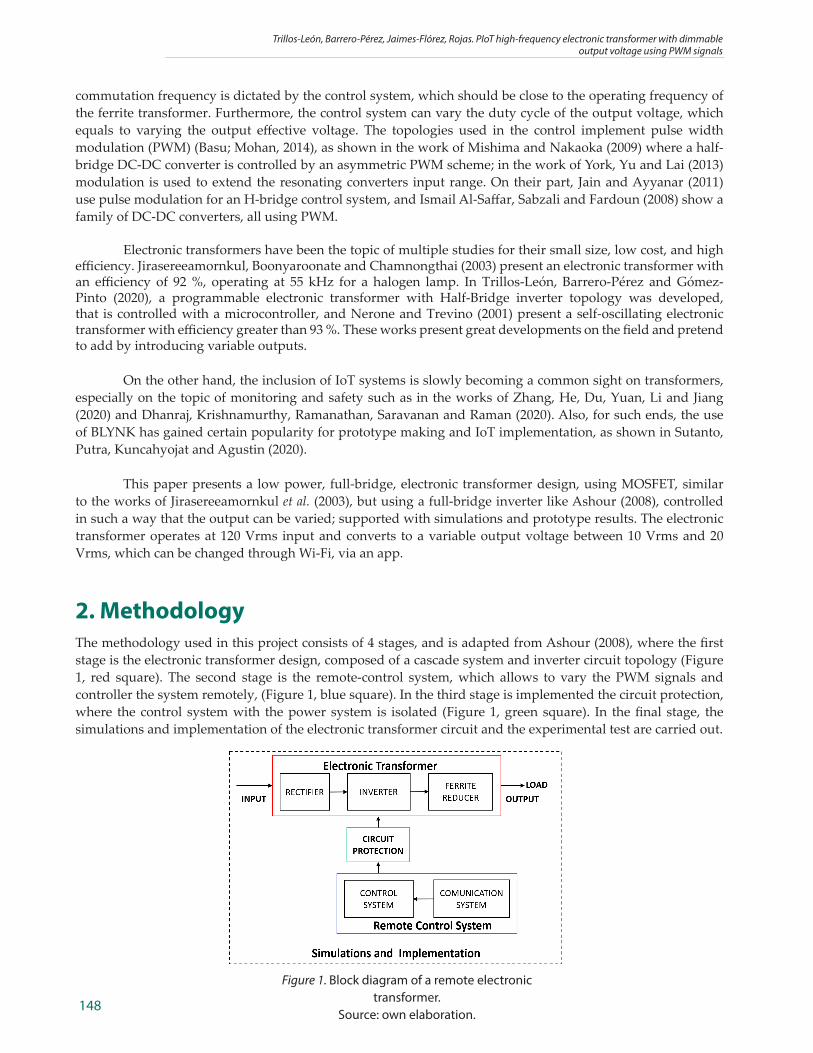
2. MethodologyThe methodology used in this project consists of 4 stages, and is adapted from Ashour (2008), where the first stage is the electronic transformer design, composed of a cascade system and inverter circuit topology (Figure 1, red square). The second stage is the remote-control system, which allows to vary the PWM signals and controller the system remotely, (Figure 1, blue square). In the third stage is implemented the circuit protection, where the control system with the power system is isolated (Figure 1, green square). In the final stage, the simulations and implementation of the electronic transformer circuit and the experimental test are carried out.
Figure 1. Block diagram of a remote electronic transformer.
Source: own elaboration.
Informador Técnico 85(2) Julio - Diciembre 2021: 146 - 159
149
2.1. Electronic Transformer DesignElectronic transformers are power electronic devices that convert an alternating voltage level to other, conserving the power (Mora, 2005). These transformers increase the frequency of operation through an inverter circuit, the inverter commutes the frequency according to the programming. These frequencies range between kHz to MHz.
Figure 1 shows the block diagram of the different stages of a remote electronic transformer. The signal input is alternating current (AC) of 60 Hz, this signal is adjusted for the cascade hardware of the electronic transformer according to the control signal proving of the remote-control system. The circuit protection is responsible for isolating the system control of the power circuit and giving strength to the control signals.
In this module, the cascade hardware will be treated; it is composed of a rectifier, an inverter, and a ferrite reducer. The rectifier adapts the AC input signal to the requirement of the inverter circuit, the inverter circuit is responsible for carrying out the high-frequency power switching process.
2.2. RectifierThe electronic transformer has a rectifier with a small capacitor on its output, thus the rectified (but not filtered) voltage, which period is half of the main voltage, feeds the inverter (Polonskii, 2004). In this project, a full-wave rectifier circuit and a polyester condenser were used.
A series of simulations were carried out to determine the better value of the capacitor, to analyze the behavior of the input current when the prototype has a load of 50 W (maximum load). First, a large capacitor (1000[μF]) and a very small capacitor (without C) gave high current peaks; but then with capacitors of 470[nF] and 100[nF] small current peaks were obtained. The capacitor 470[nF] was chosen because it has current peaks (IP) in the form of milliamps.
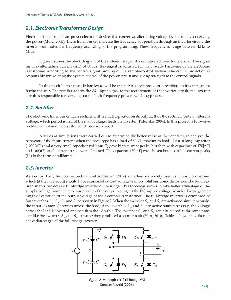
2.3. InverterAs said by Triki, Bechouche, Seddiki and Abdeslam (2019), inverters are widely used as DC-AC converters, which (if they are good) should have sinusoidal output voltage and low total harmonic distortion. The topology used in this project is a full-bridge inverter or H-Bridge. This topology allows to take better advantage of the supply voltage, since the maximum value of the output voltage is the DC supply voltage, which allows a greater range of variation of the output voltage of the electronic transformer. The full-bridge inverter is composed of four switches, S1+, S2+, S1- and S2- as shown in Figure 2. When the switches S1+ and S2- are activated simultaneously, the input voltage Vi appears across the load, if the switches S2+ and S1- are active simultaneously, the voltage across the load is inverted and acquires the -Vi value. The switches S1+ and S1- can’t be closed at the same time, just like the switches S2+ and S2-, because they produced a short-circuit (Hart, 2010). Table 1 shows the different activation stages of the full-bridge inverter.
Figure 2. Monophasic full-bridge VSI.Source: Rashid (2006).
Trillos-León, Barrero-Pérez, Jaimes-Flórez, Rojas. PIoT high-frequency electronic transformer with dimmable output voltage using PWM signals
150
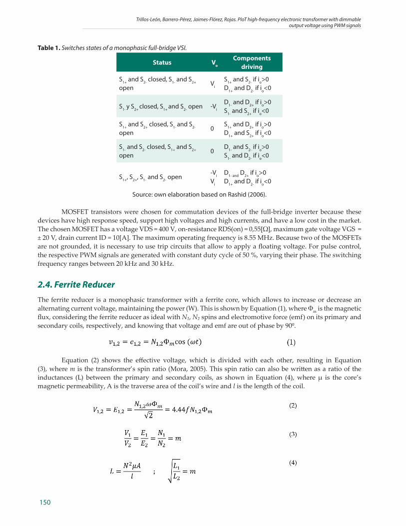
Table 1. Switches states of a monophasic full-bridge VSI.
Status Vo
Components driving
S1+ and S2- closed, S1- and S2+
openVi
S1+ and S2- if io>0D1+ and D2- if io<0
S1- y S2+ closed, S1+ and S2- open -Vi
D1- and D2+ if io>0S1- and S2+ if io<0
S1+ and S2+ closed, S1- and S2-
open0
S1+ and D2+ if io>0D1+ and S2+ if io<0
S1- and S2- closed, S1+ and S2+ open
0D1- and S2- if io>0S1- and D2- if io<0
S1+, S2+, S1- and S2- open-Vi
Vi
D1- and D2+ if io>0D1+ and D2- if io<0
Source: own elaboration based on Rashid (2006).
MOSFET transistors were chosen for commutation devices of the full-bridge inverter because these devices have high response speed, support high voltages and high currents, and have a low cost in the market. The chosen MOSFET has a voltage VDS = 400 V, on-resistance RDS(on) = 0,55[Ω], maximum gate voltage VGS = ± 20 V, drain current ID = 10[A]. The maximum operating frequency is 8.55 MHz. Because two of the MOSFETs are not grounded, it is necessary to use trip circuits that allow to apply a floating voltage. For pulse control, the respective PWM signals are generated with constant duty cycle of 50 %, varying their phase. The switching frequency ranges between 20 kHz and 30 kHz.
2.4. Ferrite ReducerThe ferrite reducer is a monophasic transformer with a ferrite core, which allows to increase or decrease an alternating current voltage, maintaining the power (W). This is shown by Equation (1), where Φm is the magnetic flux, considering the ferrite reducer as ideal with N₁, N₂ spins and electromotive force (emf) on its primary and secondary coils, respectively, and knowing that voltage and emf are out of phase by 90º.
Equation (2) shows the effective voltage, which is divided with each other, resulting in Equation (3), where m is the transformer’s spin ratio (Mora, 2005). This spin ratio can also be written as a ratio of the inductances (L) between the primary and secondary coils, as shown in Equation (4), where μ is the core’s magnetic permeability, A is the traverse area of the coil’s wire and l is the length of the coil.
Informador Técnico 85(2) Julio - Diciembre 2021: 146 - 159
151
This project used a transformer extracted from a halogen lamp CD00003902, that was characterized in the laboratory to obtain the range of work frequency with a test without load; the optimal work frequency was found to be between 10 kHz and 1 Mhz. Furthermore, the spin ratio was determined using Equation (4), with L1= 9,6 [mH] and L2 = 456 [μH] resulting in m = 4.58831.
2.5. Remote Control SystemTraditionally, the control of the bridge gates is done with self-oscillating switching systems, which are also being worked on nowadays by Zotov, Razinkin and Atuchin (2017). But to have more control over the prototype, a different approach was taken, using a microcontroller (μC) to coordinate the gates. To control the full-bridge commutation, an ESP32 microcontroller is used, due to its low cost and energy consumption. The control is done using 4 PWM signals with a max DC of 50 %, and a variable phase. Further, the ESP32 possesses a Wi-Fi module, which connects the control system to a local Wi-Fi network that communicates via an app to a mobile device, to allow better control during testing.
2.5.1. Control SystemThe ESP32 possesses a PWM module for motor control (MCPWM). This module can create three timers, which can create over six PWM signals that can be synchronized or offset by a certain degree (Espressif, 2018).
To control the full-bridge, four PWM signals were generated, one for each MOSFET, with an offset of π[rad] between, S1- , S2+ and between S1+ , S2-, so the inverter does not short circuit; this is done using function mcpwm_set_duty_type(). All signals have a duty cycle lesser than 50%, such that the dead time Td = 2[μs], this is done using the function mcpwm_set_duty_in_us(). To keep all signals synchronized to the same time frame, a fifth PWM signal was generated as an anchor for the other four, using function mcpwm_sync_enable() (Espressif, 2018).
The resulting output (Vo) signal is equal to (S1+∩ S2-) ∪ (S2+ ∩ S1-). The duty cycle of this signal is controlled in the user interface using the function mcpwm_deadtime_enable(). Further, a 2[μs] offset is given to S1+ and S2- to achieve the dead time on both sides of the pulses; 3π/4 to π.
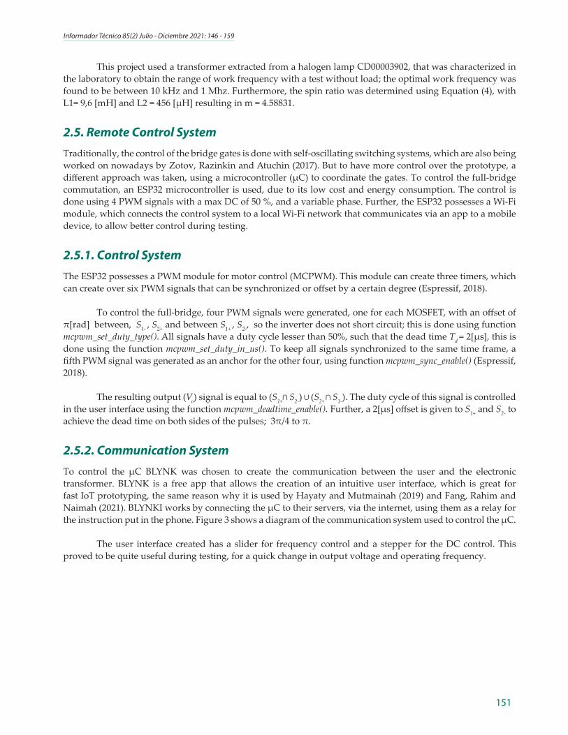
2.5.2. Communication SystemTo control the μC BLYNK was chosen to create the communication between the user and the electronic transformer. BLYNK is a free app that allows the creation of an intuitive user interface, which is great for fast IoT prototyping, the same reason why it is used by Hayaty and Mutmainah (2019) and Fang, Rahim and Naimah (2021). BLYNKI works by connecting the μC to their servers, via the internet, using them as a relay for the instruction put in the phone. Figure 3 shows a diagram of the communication system used to control the μC.
The user interface created has a slider for frequency control and a stepper for the DC control. This proved to be quite useful during testing, for a quick change in output voltage and operating frequency.
Trillos-León, Barrero-Pérez, Jaimes-Flórez, Rojas. PIoT high-frequency electronic transformer with dimmable output voltage using PWM signals
152
Figure 3. Communication system block.Source: own elaboration.
2.6. Circuit ProtectionTo protect the transistors, a TLP driver (TLP250) was used, one connected to each MOSFET, which receives the PWM signal from the μC and adjusts it to the right voltage to switch on and off the MOSFETs. The TLP is a component that can protect the control system, due to its electrical isolation. Because two of the MOSFETs are not grounded, it is necessary to use trip circuits that allow applying a floating voltage, for this purpose, an unregulated DC/DC module is used (DCP010515B), followed by a regulation step using an LM (LM78L12); a set of these is connected to every MOSFET. Moreover, each converter has its input electrically isolated from its output, creating three power sources. This setup is powered by an external source.
3. Simulations and prototypingPSpice (Orcad) was the software used for simulations. The input voltage was 120 Vrms, 60 Hz (the same as the electrical grid). For the control signal, a dead time of Tm= 2 [μs] was chosen; and the ratio of the transformer was chosen to be m = 4.59.
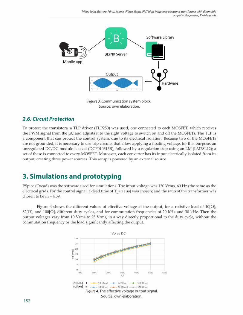
Figure 4 shows the different values of effective voltage at the output, for a resistive load of 10[Ω], 82[Ω], and 100[Ω], different duty cycles, and for commutation frequencies of 20 kHz and 30 kHz. Then the output voltages vary from 10 Vrms to 25 Vrms, in a way directly proportional to the duty cycle, without the commutation frequency or the load significantly affecting the output.
Figure 4. The effective voltage output signal.Source: own elaboration.
Informador Técnico 85(2) Julio - Diciembre 2021: 146 - 159
153
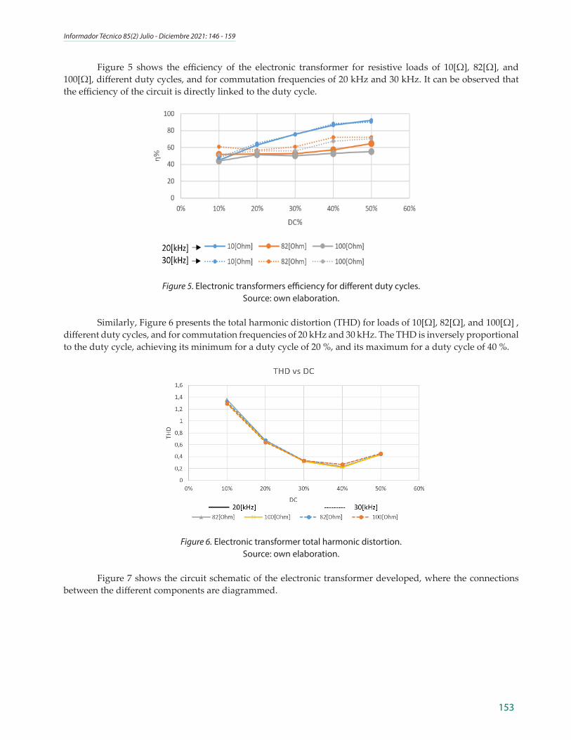
Figure 5 shows the efficiency of the electronic transformer for resistive loads of 10[Ω], 82[Ω], and 100[Ω], different duty cycles, and for commutation frequencies of 20 kHz and 30 kHz. It can be observed that the efficiency of the circuit is directly linked to the duty cycle.
Figure 5. Electronic transformers efficiency for different duty cycles.Source: own elaboration.
Similarly, Figure 6 presents the total harmonic distortion (THD) for loads of 10[Ω], 82[Ω], and 100[Ω] , different duty cycles, and for commutation frequencies of 20 kHz and 30 kHz. The THD is inversely proportional to the duty cycle, achieving its minimum for a duty cycle of 20 %, and its maximum for a duty cycle of 40 %.
Figure 6. Electronic transformer total harmonic distortion.Source: own elaboration.
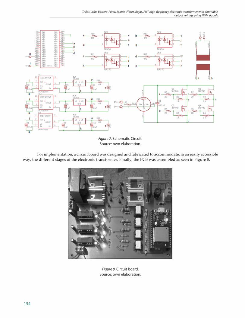
Figure 7 shows the circuit schematic of the electronic transformer developed, where the connections between the different components are diagrammed.
Trillos-León, Barrero-Pérez, Jaimes-Flórez, Rojas. PIoT high-frequency electronic transformer with dimmable output voltage using PWM signals
154
Figure 7. Schematic Circuit.Source: own elaboration.
For implementation, a circuit board was designed and fabricated to accommodate, in an easily accessible way, the different stages of the electronic transformer. Finally, the PCB was assembled as seen in Figure 8.
Figure 8. Circuit board.Source: own elaboration.
Informador Técnico 85(2) Julio - Diciembre 2021: 146 - 159
155
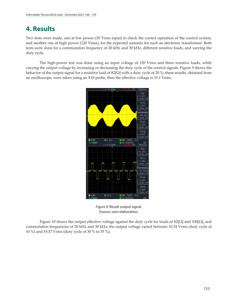
4. ResultsTwo tests were made, one at low power (30 Vrms input) to check the correct operation of the control system, and another one at high power (120 Vrms), for the expected scenario for such an electronic transformer. Both tests were done for a commutation frequency of 20 kHz and 30 kHz, different resistive loads, and varying the duty cycle.
The high-power test was done using an input voltage of 120 Vrms and three resistive loads, while varying the output voltage by increasing or decreasing the duty cycle of the control signals. Figure 9 shows the behavior of the output signal for a resistive load of 82[Ω] with a duty cycle of 20 %; these results, obtained from an oscilloscope, were taken using an X10 probe, then the effective voltage is 15.1 Vrms.
Figure 9. Result output signal.Source: own elaboration.
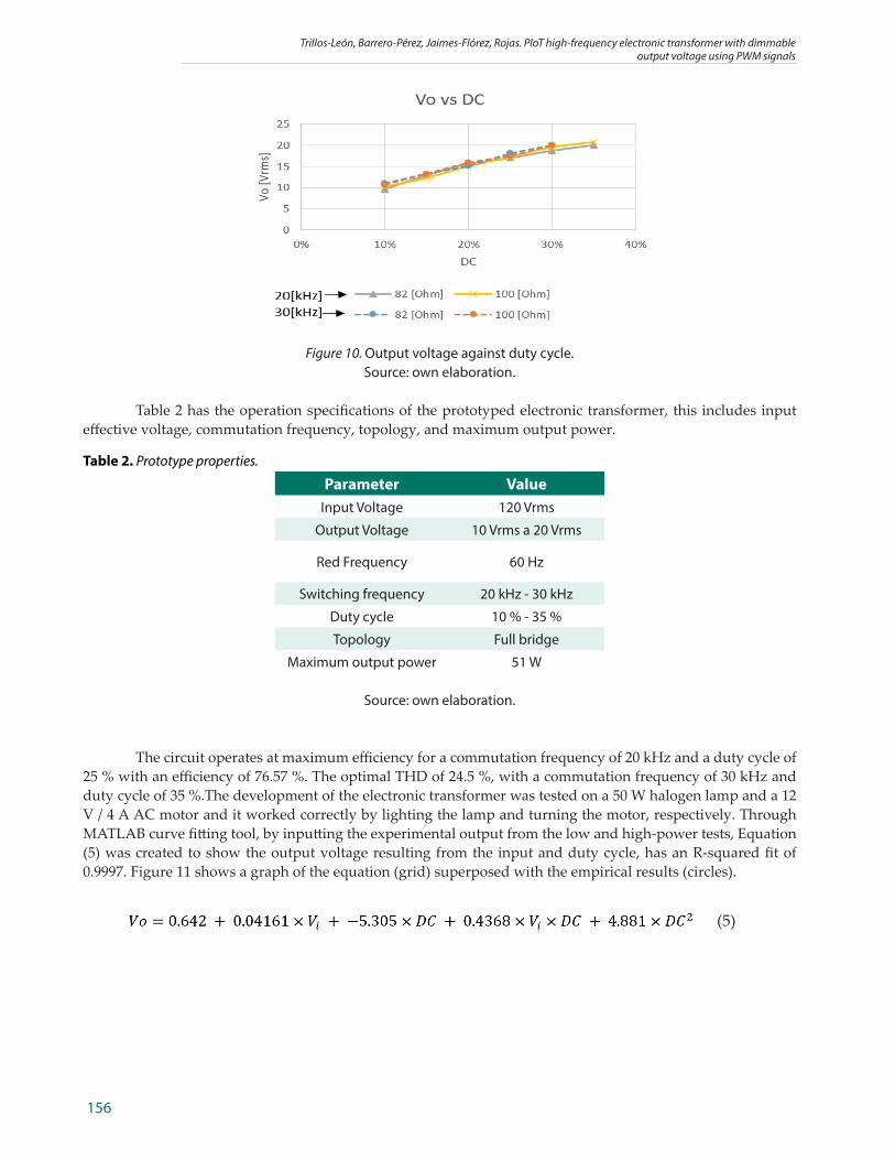
Figure 10 shows the output effective voltage against the duty cycle for loads of 82[Ω] and 100[Ω], and commutation frequencies of 20 kHz and 30 kHz; the output voltage varied between 10,34 Vrms (duty cycle of 10 %) and 19,57 Vrms (duty cycle of 30 % to 35 %).
Trillos-León, Barrero-Pérez, Jaimes-Flórez, Rojas. PIoT high-frequency electronic transformer with dimmable output voltage using PWM signals
156
Figure 10. Output voltage against duty cycle.Source: own elaboration.
Table 2 has the operation specifications of the prototyped electronic transformer, this includes input effective voltage, commutation frequency, topology, and maximum output power.
Table 2. Prototype properties.
Parameter ValueInput Voltage 120 Vrms
Output Voltage 10 Vrms a 20 Vrms
Red Frequency 60 Hz
Switching frequency 20 kHz - 30 kHz
Duty cycle 10 % - 35 %
Topology Full bridge
Maximum output power 51 W
Source: own elaboration.
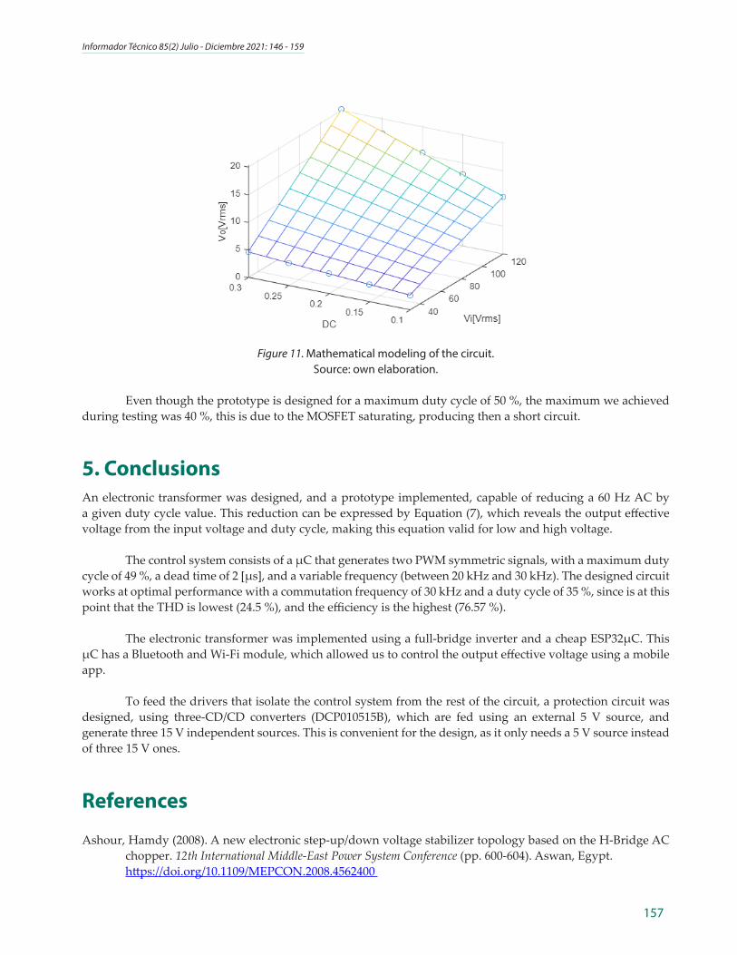
The circuit operates at maximum efficiency for a commutation frequency of 20 kHz and a duty cycle of 25 % with an efficiency of 76.57 %. The optimal THD of 24.5 %, with a commutation frequency of 30 kHz and duty cycle of 35 %.The development of the electronic transformer was tested on a 50 W halogen lamp and a 12 V / 4 A AC motor and it worked correctly by lighting the lamp and turning the motor, respectively. Through MATLAB curve fitting tool, by inputting the experimental output from the low and high-power tests, Equation (5) was created to show the output voltage resulting from the input and duty cycle, has an R-squared fit of 0.9997. Figure 11 shows a graph of the equation (grid) superposed with the empirical results (circles).
(5)
Informador Técnico 85(2) Julio - Diciembre 2021: 146 - 159
157
Figure 11. Mathematical modeling of the circuit.Source: own elaboration.
Even though the prototype is designed for a maximum duty cycle of 50 %, the maximum we achieved during testing was 40 %, this is due to the MOSFET saturating, producing then a short circuit.
5. ConclusionsAn electronic transformer was designed, and a prototype implemented, capable of reducing a 60 Hz AC by a given duty cycle value. This reduction can be expressed by Equation (7), which reveals the output effective voltage from the input voltage and duty cycle, making this equation valid for low and high voltage.
The control system consists of a μC that generates two PWM symmetric signals, with a maximum duty cycle of 49 %, a dead time of 2 [μs], and a variable frequency (between 20 kHz and 30 kHz). The designed circuit works at optimal performance with a commutation frequency of 30 kHz and a duty cycle of 35 %, since is at this point that the THD is lowest (24.5 %), and the efficiency is the highest (76.57 %).
The electronic transformer was implemented using a full-bridge inverter and a cheap ESP32μC. This μC has a Bluetooth and Wi-Fi module, which allowed us to control the output effective voltage using a mobile app.
To feed the drivers that isolate the control system from the rest of the circuit, a protection circuit was designed, using three-CD/CD converters (DCP010515B), which are fed using an external 5 V source, and generate three 15 V independent sources. This is convenient for the design, as it only needs a 5 V source instead of three 15 V ones.
References
Ashour, Hamdy (2008). A new electronic step-up/down voltage stabilizer topology based on the H-Bridge AC chopper. 12th International Middle-East Power System Conference (pp. 600-604). Aswan, Egypt.
https://doi.org/10.1109/MEPCON.2008.4562400
Trillos-León, Barrero-Pérez, Jaimes-Flórez, Rojas. PIoT high-frequency electronic transformer with dimmable output voltage using PWM signals
158
Basu, Kaushi; Mohan, Ned (2014). A Single-Stage Power Electronic Transformer for a Three-Phase PWM AC/AC Drive With Source-Based Commutation of Leakage Energy and Common-Mode Voltage Suppression. IEEE Transactions on Industrial Electronics, 61(11), 5881-5893.
https://doi.org/10.1109/TIE.2014.2311393
Battal, Funda; Balci, Selami; Sefa, Ibrahim (2021). Power electronic transformers: a review. Measurement, 171, 108848. https://doi.org/10.1016/j.measurement.2020.108848
Dhanraj, Joshuva; Krishnamurthy, Balachandar; Ramanathan, Kuppan; Saravanan, A. K.; Raman, Jeya (2020). Design on IoT Based Real Time Transformer Performance Monitoring System for Enhancing the Safety Measures. IOP Conference Series. Materials Science and Engineering, 988(1), 012076.
https://doi.org/10.1088/1757-899X/988/1/012076
Dujic, Drazen; Kieferndorf, Frederick; Canales, Francisco; Drofeni, Uwe (2012). Power electronic traction transformer technology. Proceedings of The 7th International Power Electronics and Motion Control Conference (pp. 636-642). Harbin, China.
https://doi.org/10.1109/IPEMC.2012.6258820
Espressif (2018). Espressif. Retrieved from https://docs.espressif.com/projects/esp-idf/en/latest/esp32/api-reference/peripherals/mcpwm.html
Fang, Liew; Rahim, Resemi; Naimah, Siti (2021). Design of artificial piezo-leaf wind energy harvesting system monitoring based on Blynk apps. AIP Conference Proceedings, 2339(1), 20005.
https://doi.org/10.1063/5.0044292
Hart, Daniel (2010). Power Electronics. Valparaiso, IN, USA: McGraw Hill.
Hayaty, Mardhiya; Mutmainah, Ade (2019). IoT-Based electricity usage monitoring and controlling system using Wemos and Blynk application. Jurnal Teknologi Dan Sistem Komputer, 7(4), 161-165.
https://doi.org/10.14710/jtsiskom.7.4.2019.161-165
He, Rongzhen; Zhang, Yanli; Zhang, Dianhai; Xie, Dexin (2018). An Improvement of Core Losses Estimation Model in Power Electronic Transformer. IEEE Student Conference on Electric Machines and Systems (pp. 1-5). Huzhou, China.
https://doi.org/10.1109/SCEMS.2018.8624711
Ismail, Esan; Al-Saffar, Mustafa; Sabzali, Ahmad; Fardoun, Abbas (2008). A Family of Single-Switch PWM Converters With High Step-Up Conversion Ratio. IEEE Transactions on Circuits and Systems I: Regular Papers, 55(4), 1159-1171.
https://doi.org/10.1109/TCSI.2008.916427
Jain, Amit; Ayyanar, Raja (2011). Pwm control of dual active bridge: Comprehensive analysis and experimental verification. IEEE Transactions on Power Electronics, 26(4), 1215-1227.
https://doi.org/10.1109/TPEL.2010.2070519
Jirasereeamornkul, Kamon; Boonyaroonate, Itsda; Chamnongthai, Kosin (2003). High-efficiency electronic transformer for low. IEEE International Symposium on Circuits and Systems (ISCAS) (p. 3). Bangkok, Thailand. https://doi.org/10.1109/ISCAS.2003.1205029
Keke, Liu; Lin, Li (2014). Analysis of favored design frequency of high-frequency transformer with different power capacities. International Conference on Power System Technology (POWERCON) (pp. 2272-2278). Chengdu, China.
https://doi.org/10.1109/POWERCON.2014.6993764

Informador Técnico 85(2) Julio - Diciembre 2021: 146 - 159
159
Kumar, Seshasai (2016). Design of high frequency power transformer for switched mode power supplies. International Conference on Emerging Trends in Engineering, Technology and Science (ICETETS) (pp. 1-5). Pudukkottai, India.
https://doi.org/10.1109/ICETETS.2016.7603076
Mishima, Tomokazu; Nakaoka, Mutsuo (2009). A Novel High-Frequency Transformer-Linked Soft-Switching Half-Bridge DC–DC Converter With Constant-Frequency Asymmetrical PWM Scheme. IEEE Transactions on Industrial Electronics, 56(8), 2961-2969.
https://doi.org/10.1109/TIE.2009.2013692
Mora, Jesús (2005). Maquinas Electricas. Madrid, España: McGraw Hill.
Nerone, Louis R.; Trevino, B. (2001). A new halogen electronic transformer. Sixteenth Annual IEEE Applied Power Electronics Conference and Exposition (pp. 461-466). Anaheim, CA, USA.
https://doi.org/10.1109/APEC.2001.911687
Polonskii, M. (2004). Design procedure for dimmable electronic transformer. IEEE International Conference on Industrial Technology (pp. 695-700). Hammamet, Tunisia.
https://doi.org/10.1109/ICIT.2004.1490159
Rashid, Muhammad (2006). Power Electronics. Circuits, Devices and Applications. New Jersey, NJ, USA: Pearson Prentice Hall.
Sutanto, Erwin; Putra, Tomy; Kuncahyojat, Anindriyo; Agustin, Eva (2020). IoT based electricity leakage current monitoring using Blynk app. AIP Conference Proceedings, 2314(1), 40004.
https://doi.org/10.1063/5.0034352
Triki, Yacine; Bechouche, Ali; Seddiki, Hamid; Abdeslam, Djaffar (2019). High Performance Control of Single-Phase Full Bridge Inverters Under Linear and Nonlinear Loads. IECON 2019 - 45th Annual Conference of the IEEE Industrial Electronics Society (pp. 400-405). Lisbon, Portugal.
https://doi.org/10.1109/IECON.2019.8927102
Trillos-León, Nelson-Enrique; Barrero-Pérez, Jaime-Guillermo; Gómez Pinto, Jorge-Eliecer (2020). Diseño y construcción de un transformador electrónico 12 Vrms 50 W con control de frecuencia de conmutación programable. Scientia et Technica, 25(3), 358-366.
https://doi.org/10.22517/23447214.24251
York, Ben; Yu, Wensong; Lai, Jason (2013). Hybrid-Frequency Modulation for PWM-Integrated Resonant Converters. IEEE Transactions on Power Electronics, 28(2), 985-994.
https://doi.org/10.1109/TPEL.2012.2201960
Zhang, Chaolong; He, Yigang; Du, Bolun; Yuan, Lifen; Li, Bing; Jiang, Shanhe (2020). Transformer fault diagnosis method using IoT based monitoring system and ensemble machine learning. Future Generation Computer Systems, 108, 533–545.
https://doi.org/https://doi.org/10.1016/j.future.2020.03.008
Zhang, Darning; Tseng, King-Jet (2006). Effect of high permittivity and core dimensions on the permeability measurement for Mn-Zn ferrite cores used in high-frequency transformer. Third IEEE International Workshop on Electronic Design, Test and Applications (DELTA’06) (p. 378). Kuala Lumpur, Malaysia. https://doi.org/10.1109/DELTA.2006.40
Zotov, Leonid-Grigoryevich; Razinkin, Vladimir P.; Atuchin, Victor V. (2017). Controllable electronic transformer based on the resonance structure with switching capacitor for low-rise buildings residential area power supply stabilization systems. International Journal of Electrical Power & Energy Systems, 91, 117-120. https://doi.org/https://doi.org/10.1016/j.ijepes.2017.03.004