Embed Size (px)
Citation preview
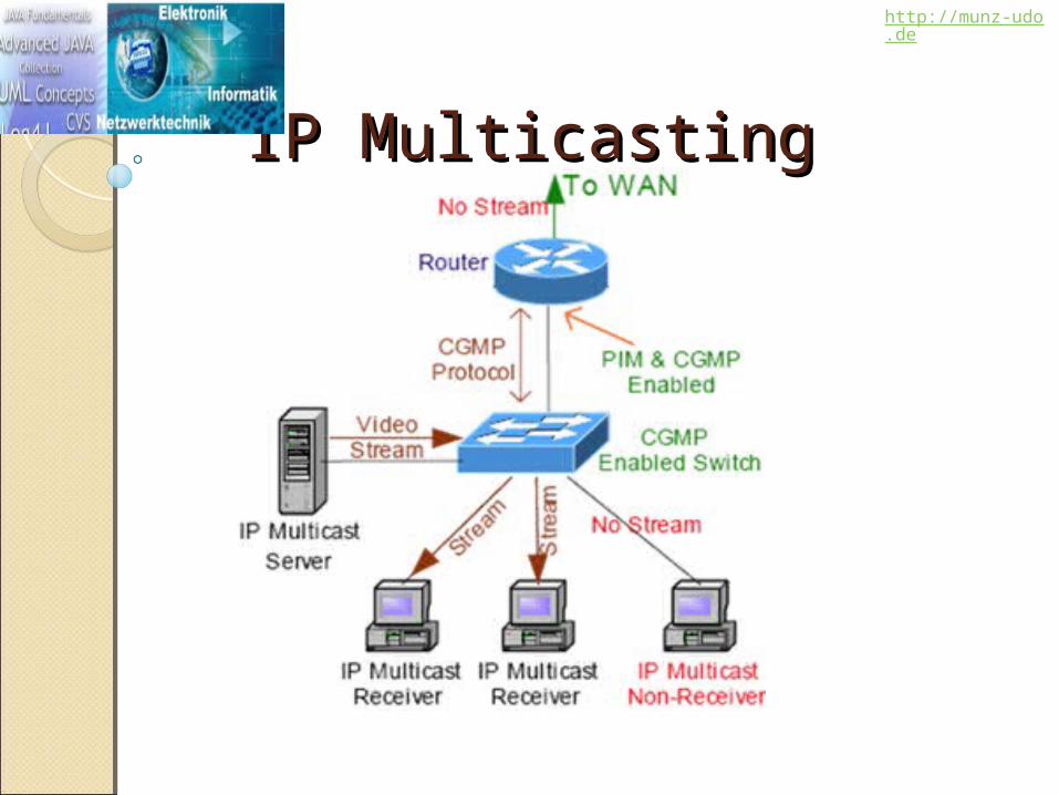
IP MulticastingIP Multicasting
http://munz-udo.de
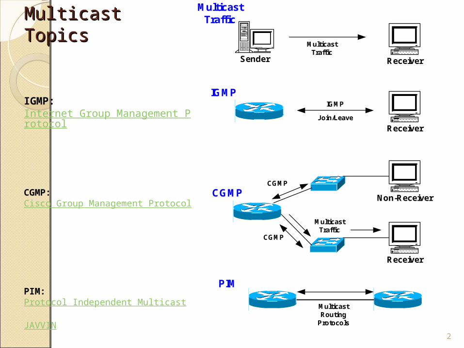
Multicast TopicsMulticast Topics
2
Sender Receiver
Receiver
Non-Receiver
Receiver
CGMP
CGMP
MulticastTraffic
MulticastTraffic
Join/Leave
IGMP
IGMP
CGMP
MulticastTraffic
MulticastRouting
Protocols
PIM
IGMP: Internet Group Management Protocol
CGMP: Cisco Group Management Protocol
PIM: Protocol Independent Multicast
JAVVIN
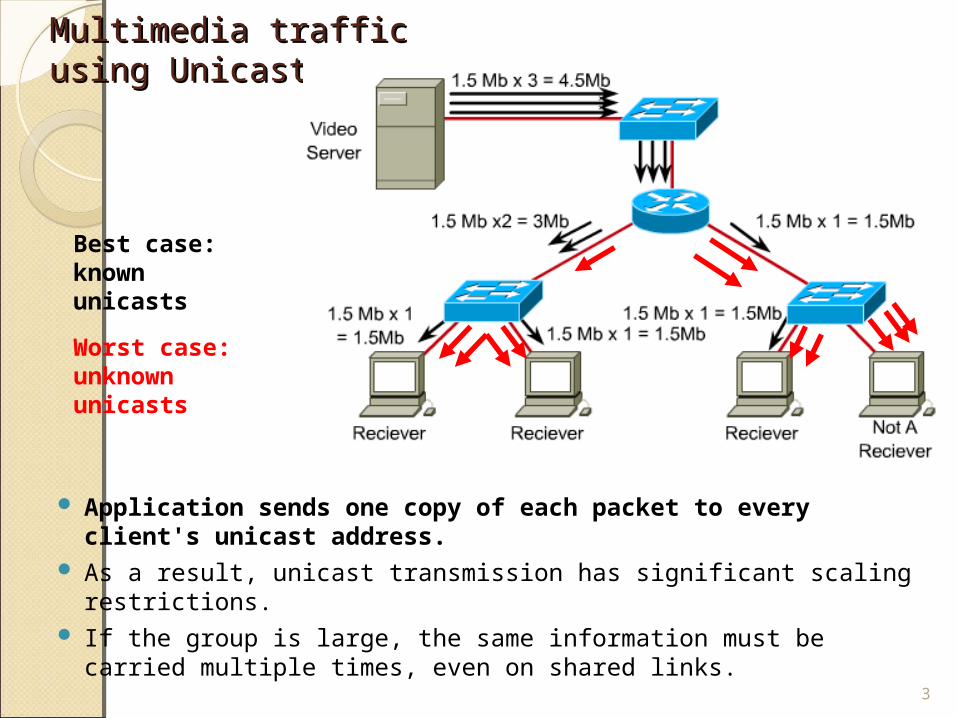
Multimedia traffic using Multimedia traffic using UnicastUnicast
Application sends one copy of each packet to every client's unicast address.
As a result, unicast transmission has significant scaling restrictions.
If the group is large, the same information must be carried multiple times, even on shared links.
3
Best case: known unicasts
Worst case: unknown unicasts
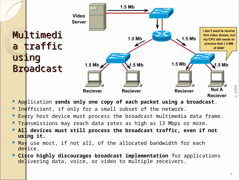
Multimedia Multimedia traffic traffic using using BroadcastBroadcast
Application sends only one copy of each packet using a broadcast.
Inefficient, if only for a small subset of the network. Every host device must process the broadcast multimedia data frame. Transmissions may reach data rates as high as 13 Mbps or more. All devices must still process the broadcast traffic, even if not
using it. May use most, if not all, of the allocated bandwidth for each device. Cisco highly discourages broadcast implementation for
applications delivering data, voice, or video to multiple receivers.4
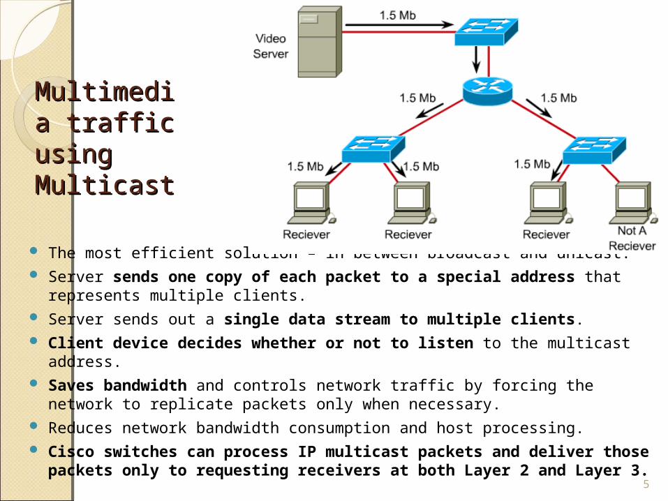
MultimediMultimedia traffic a traffic using using MulticastMulticast
The most efficient solution – in between broadcast and unicast. Server sends one copy of each packet to a special address that
represents multiple clients. Server sends out a single data stream to multiple clients. Client device decides whether or not to listen to the multicast
address. Saves bandwidth and controls network traffic by forcing the network to
replicate packets only when necessary. Reduces network bandwidth consumption and host processing. Cisco switches can process IP multicast packets and deliver those
packets only to requesting receivers at both Layer 2 and Layer 3.5
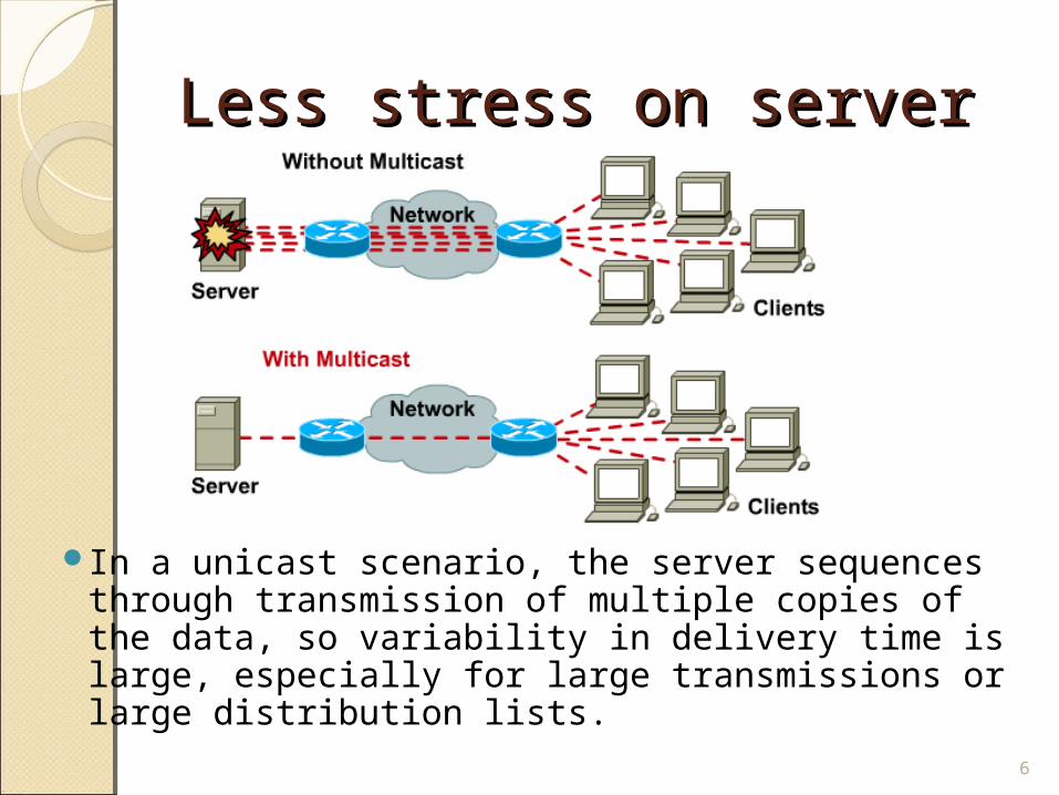
Less stress on serverLess stress on server
In a unicast scenario, the server sequences through transmission of multiple copies of the data, so variability in delivery time is large, especially for large transmissions or large distribution lists.
6
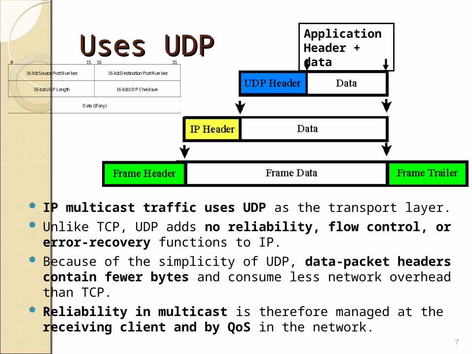
Uses UDPUses UDP
IP multicast traffic uses UDP as the transport layer. Unlike TCP, UDP adds no reliability, flow control, or error-
recovery functions to IP. Because of the simplicity of UDP, data-packet headers
contain fewer bytes and consume less network overhead than TCP.
Reliability in multicast is therefore managed at the receiving client and by QoS in the network.
7
Application Header + data
0 15 16 31
16-bit Source Port Number
16-bit Destination Port Number
16-bit UDP Length
16-bit UDP Checksum
Data (if any)
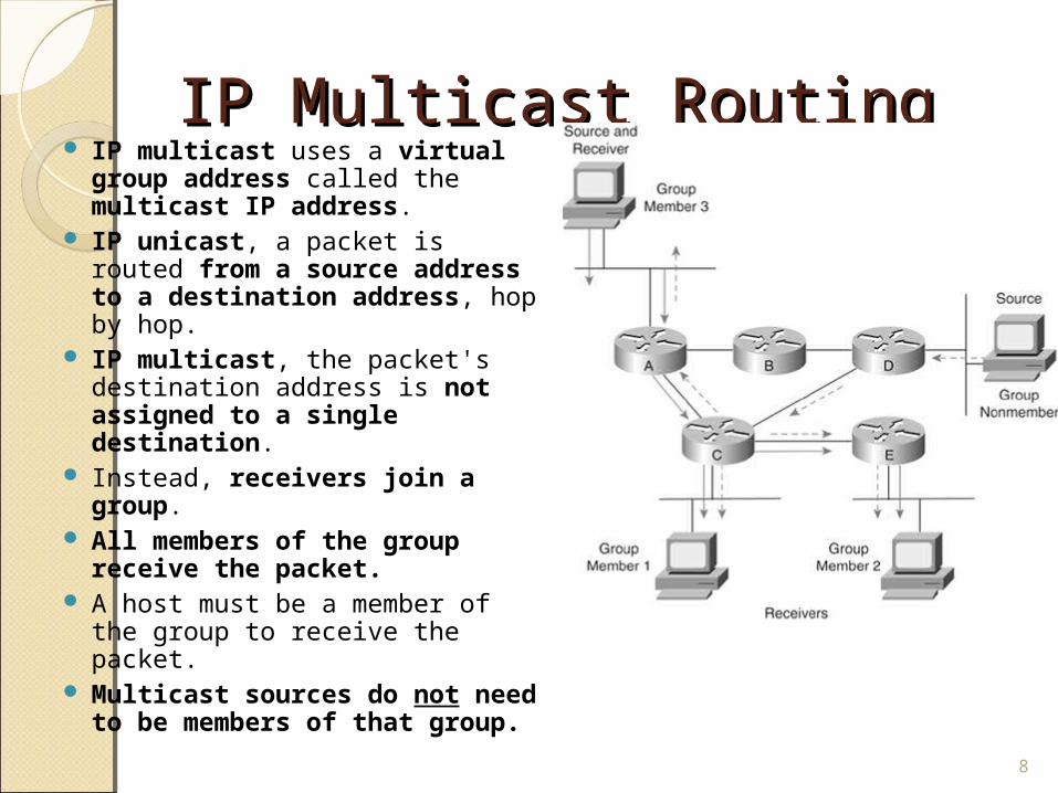
IP Multicast RoutingIP Multicast Routing IP multicast uses a virtual
group address called the multicast IP address.
IP unicast, a packet is routed from a source address to a destination address, hop by hop.
IP multicast, the packet's destination address is not assigned to a single destination.
Instead, receivers join a group.
All members of the group receive the packet.
A host must be a member of the group to receive the packet.
Multicast sources do not need to be members of that group. 8
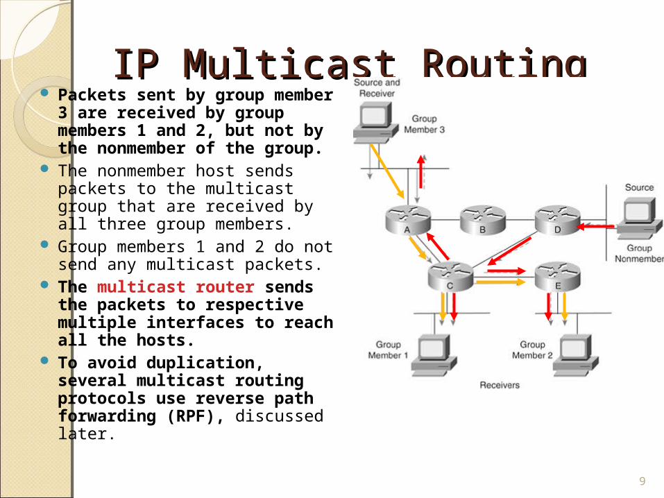
IP Multicast RoutingIP Multicast Routing Packets sent by group
member 3 are received by group members 1 and 2, but not by the nonmember of the group.
The nonmember host sends packets to the multicast group that are received by all three group members.
Group members 1 and 2 do not send any multicast packets.
The multicast router sends the packets to respective multiple interfaces to reach all the hosts.
To avoid duplication, several multicast routing protocols use reverse path forwarding (RPF), discussed later.
9
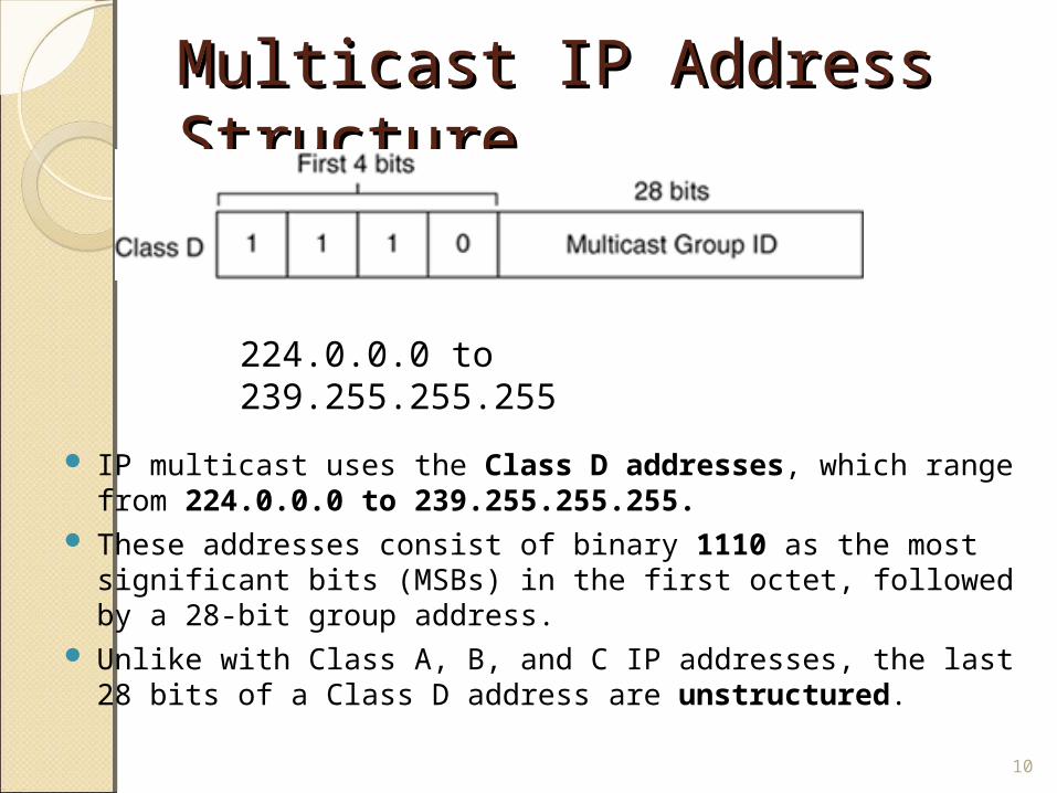
Multicast IP Address Multicast IP Address Structure Structure
IP multicast uses the Class D addresses, which range from 224.0.0.0 to 239.255.255.255.
These addresses consist of binary 1110 as the most significant bits (MSBs) in the first octet, followed by a 28-bit group address.
Unlike with Class A, B, and C IP addresses, the last 28 bits of a Class D address are unstructured.
10
224.0.0.0 to 239.255.255.255
Multicast IP Address Multicast IP Address Structure Structure
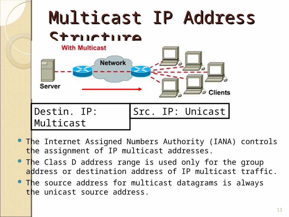
The Internet Assigned Numbers Authority (IANA) controls the assignment of IP multicast addresses.
The Class D address range is used only for the group address or destination address of IP multicast traffic.
The source address for multicast datagrams is always the unicast source address.
11
Destin. IP: Multicast Src. IP: Unicast
Multicast IP Address Multicast IP Address Structure Structure
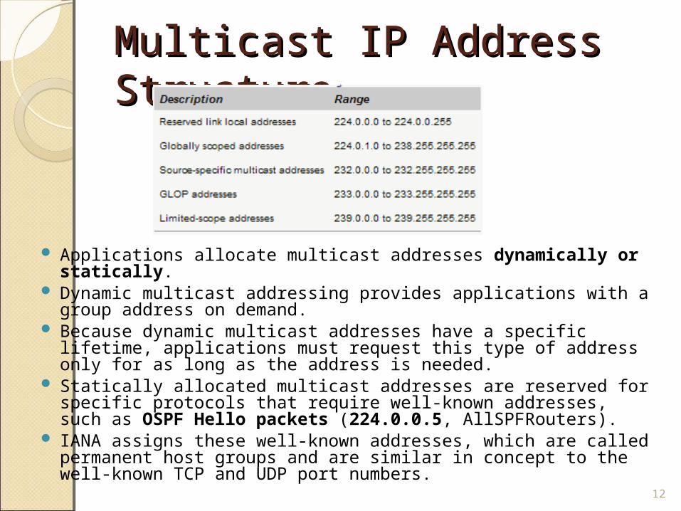
Applications allocate multicast addresses dynamically or statically.
Dynamic multicast addressing provides applications with a group address on demand.
Because dynamic multicast addresses have a specific lifetime, applications must request this type of address only for as long as the address is needed.
Statically allocated multicast addresses are reserved for specific protocols that require well-known addresses, such as OSPF Hello packets (224.0.0.5, AllSPFRouters).
IANA assigns these well-known addresses, which are called permanent host groups and are similar in concept to the well-known TCP and UDP port numbers.
12
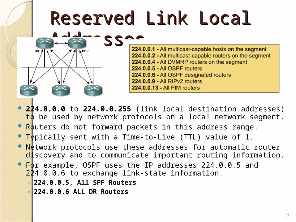
Reserved Link Local Reserved Link Local Addresses Addresses
224.0.0.0 to 224.0.0.255 (link local destination addresses) to be used by network protocols on a local network segment.
Routers do not forward packets in this address range. Typically sent with a Time-to-Live (TTL) value of 1. Network protocols use these addresses for automatic router
discovery and to communicate important routing information. For example, OSPF uses the IP addresses 224.0.0.5 and
224.0.0.6 to exchange link-state information. ◦ 224.0.0.5, All SPF Routers◦ 224.0.0.6 ALL DR Routers
13
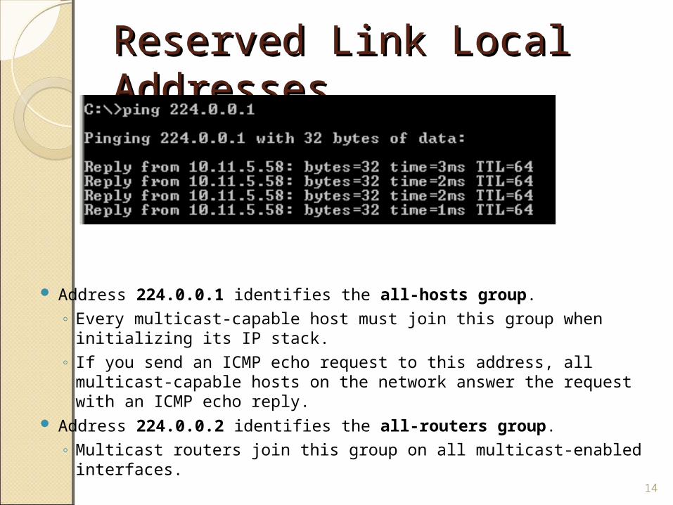
Reserved Link Local Reserved Link Local Addresses Addresses
Address 224.0.0.1 identifies the all-hosts group. ◦ Every multicast-capable host must join this group when initializing
its IP stack. ◦ If you send an ICMP echo request to this address, all multicast-
capable hosts on the network answer the request with an ICMP echo reply.
Address 224.0.0.2 identifies the all-routers group. ◦ Multicast routers join this group on all multicast-enabled
interfaces.14
mping – A simple mping – A simple demonstrationdemonstration
Use mping on two or more hosts to show how multicast hosts send and receive multicast traffic.
Mping is a little different, in that both hosts are senders and receivers.
http://research.microsoft.com/barc/mbone/mping.aspx
Hosts: mping <IP address> [port] [TTL] [time in msec between pings]
Example, both hosts: mping 224.10.10.10 When it sends a packet: "Sent packet" When it receives a packet: RCV: XX bytes from XXX.XXX.XXX.XXX
15
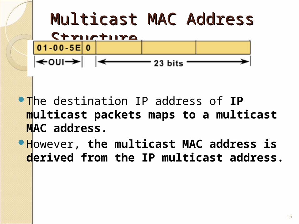
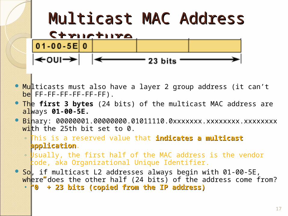
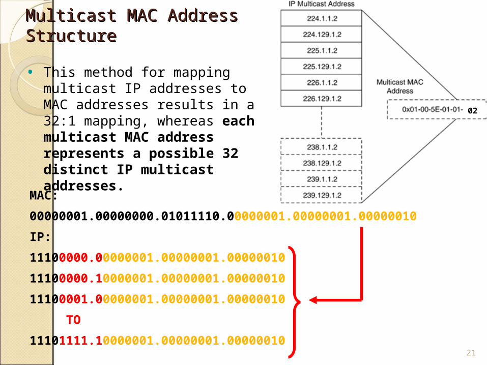
Multicast MAC Address Multicast MAC Address Structure Structure
The destination IP address of IP multicast packets maps to a multicast MAC address.
However, the multicast MAC address is derived from the IP multicast address.
16
Multicast MAC Address Multicast MAC Address Structure Structure
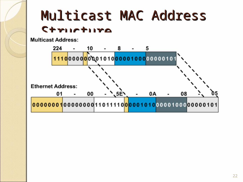
Multicasts must also have a layer 2 group address (it can’t be FF-FF-FF-FF-FF-FF).
The first 3 bytes (24 bits) of the multicast MAC address are always 01-00-5E.
Binary: 00000001.00000000.01011110.0xxxxxxx.xxxxxxxx.xxxxxxxx with the 25th bit set to 0. ◦ This is a reserved value that indicates a multicast indicates a multicast
applicationapplication. ◦ Usually, the first half of the MAC address is the vendor code,
aka Organizational Unique Identifier. So, if multicast L2 addresses always begin with 01-00-5E, where
does the other half (24 bits) of the address come from?• ““00”” + 23 bits (copied from the IP address) + 23 bits (copied from the IP address)
17
Multicast MAC Address Multicast MAC Address Structure Structure
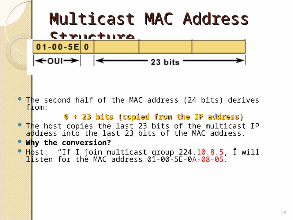
The second half of the MAC address (24 bits) derives from:0 + 23 bits (copied from the IP address)0 + 23 bits (copied from the IP address)
The host copies the last 23 bits of the multicast IP address into the last 23 bits of the MAC address.
Why the conversion? Host: “If I join multicast group 224.10.8.5, I will listen for the
MAC address 01-00-5E-0A-08-05.”
18
Multicast MAC Address Multicast MAC Address Structure Structure
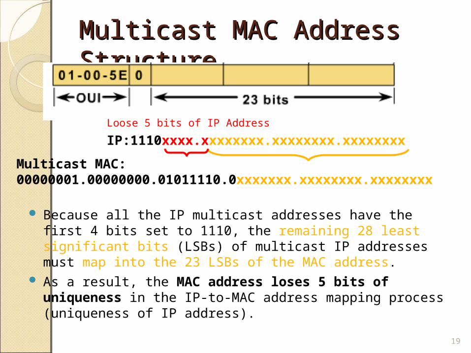
Because all the IP multicast addresses have the first 4 bits set to 1110, the remaining 28 least significant bits (LSBs) of multicast IP addresses must map into the 23 LSBs of the MAC address.
As a result, the MAC address loses 5 bits of uniqueness in the IP-to-MAC address mapping process (uniqueness of IP address).
19
Multicast MAC: 00000001.00000000.01011110.0xxxxxxx.xxxxxxxx.xxxxxxxx
IP:1110xxxx.xxxxxxxx.xxxxxxxx.xxxxxxxxLoose 5 bits of IP Address
Multicast MAC Address Multicast MAC Address Structure Structure
20
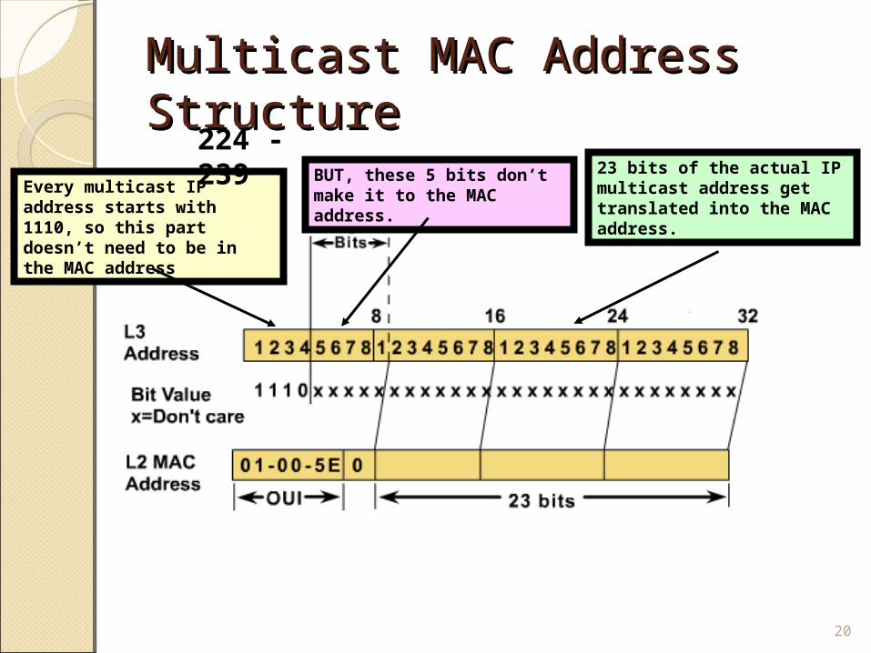
Every multicast IP address starts with 1110, so this part doesn’t need to be in the MAC address
23 bits of the actual IP multicast address get translated into the MAC address.
BUT, these 5 bits don’t make it to the MAC address.
224 - 239
Multicast MAC Address Multicast MAC Address Structure Structure
MAC:
00000001.00000000.01011110.00000001.00000001.00000010
IP:
11100000.00000001.00000001.00000010
11100000.10000001.00000001.00000010
11100001.00000001.00000001.00000010
TO
11101111.10000001.00000001.0000001021
• This method for mapping multicast IP addresses to MAC addresses results in a 32:1 mapping, whereas each multicast MAC address represents a possible 32 distinct IP multicast addresses.
02
Multicast MAC Address Multicast MAC Address Structure Structure
22
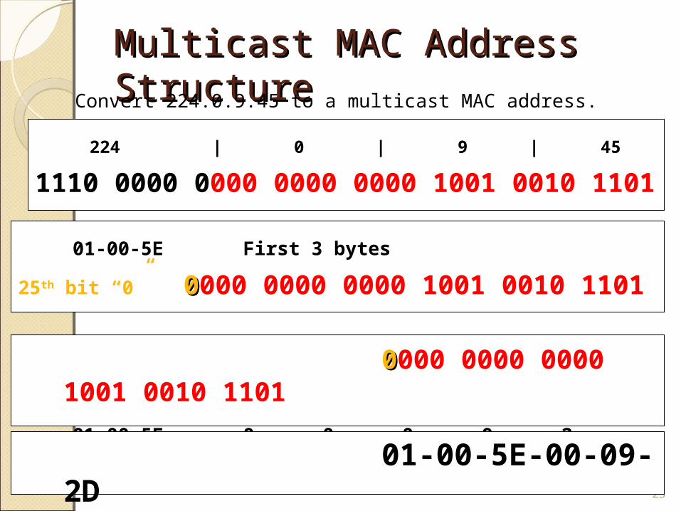
Multicast MAC Address Multicast MAC Address Structure Structure Convert 224.0.9.45 to a multicast MAC address.
23
224 | 0 | 9 | 451110 0000 0000 0000 0000 1001 0010 1101
01-00-5E First 3 bytes25th bit “0” 00000 0000 0000 1001 0010 1101
00000 0000 0000 1001 0010 1101 01-00-5E- 0 0 - 0 9 - 2 D(13)
01-00-5E-00-09-2D
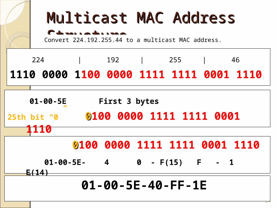
Multicast MAC Address Multicast MAC Address Structure Structure Convert 224.192.255.44 to a multicast MAC address.
24
224 | 192 | 255 | 461110 0000 1100 0000 1111 1111 0001 1110
01-00-5E First 3 bytes25th bit “0” 00100 0000 1111 1111 0001 1110
00100 0000 1111 1111 0001 1110
01-00-5E- 4 0 - F(15) F - 1 E(14)
01-00-5E-40-FF-1E
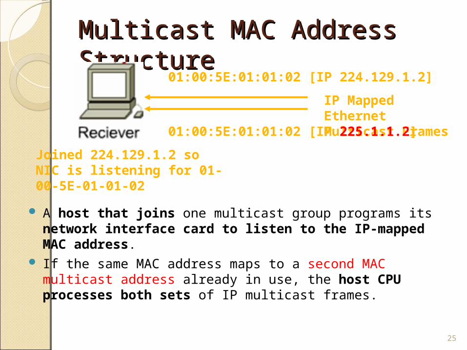
Multicast MAC Address Multicast MAC Address Structure Structure
A host that joins one multicast group programs its network interface card to listen to the IP-mapped MAC address.
If the same MAC address maps to a second MAC multicast address already in use, the host CPU processes both sets of IP multicast frames.
25
IP Mapped Ethernet Multicast Frames
01:00:5E:01:01:02 [IP 224.129.1.2]
Joined 224.129.1.2 so NIC is listening for 01-00-5E-01-01-02
01:00:5E:01:01:02 [IP 225.1.1.2]
Multicast MAC Address Multicast MAC Address Structure Structure
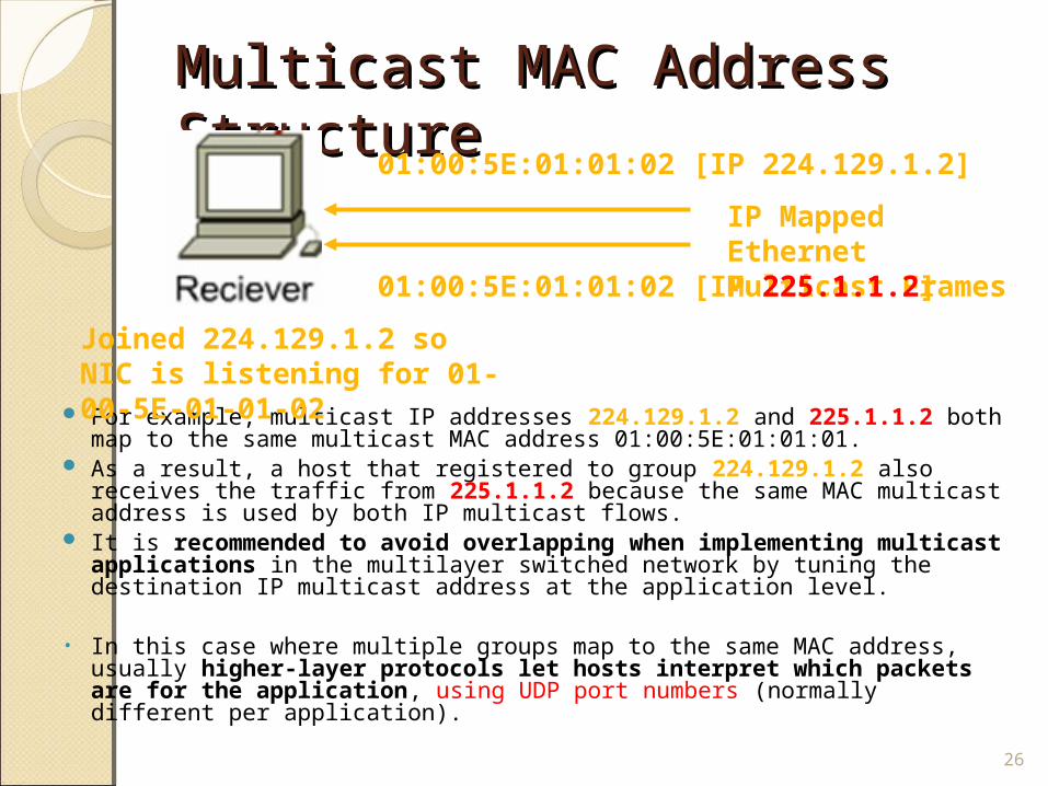
For example, multicast IP addresses 224.129.1.2 and 225.1.1.2 both map to the same multicast MAC address 01:00:5E:01:01:01.
As a result, a host that registered to group 224.129.1.2 also receives the traffic from 225.1.1.2 because the same MAC multicast address is used by both IP multicast flows.
It is recommended to avoid overlapping when implementing multicast applications in the multilayer switched network by tuning the destination IP multicast address at the application level.
• In this case where multiple groups map to the same MAC address, usually higher-layer protocols let hosts interpret which packets are for the application, using UDP port numbers (normally different per application).
26
IP Mapped Ethernet Multicast Frames
01:00:5E:01:01:02 [IP 224.129.1.2]
Joined 224.129.1.2 so NIC is listening for 01-00-5E-01-01-02
01:00:5E:01:01:02 [IP 225.1.1.2]
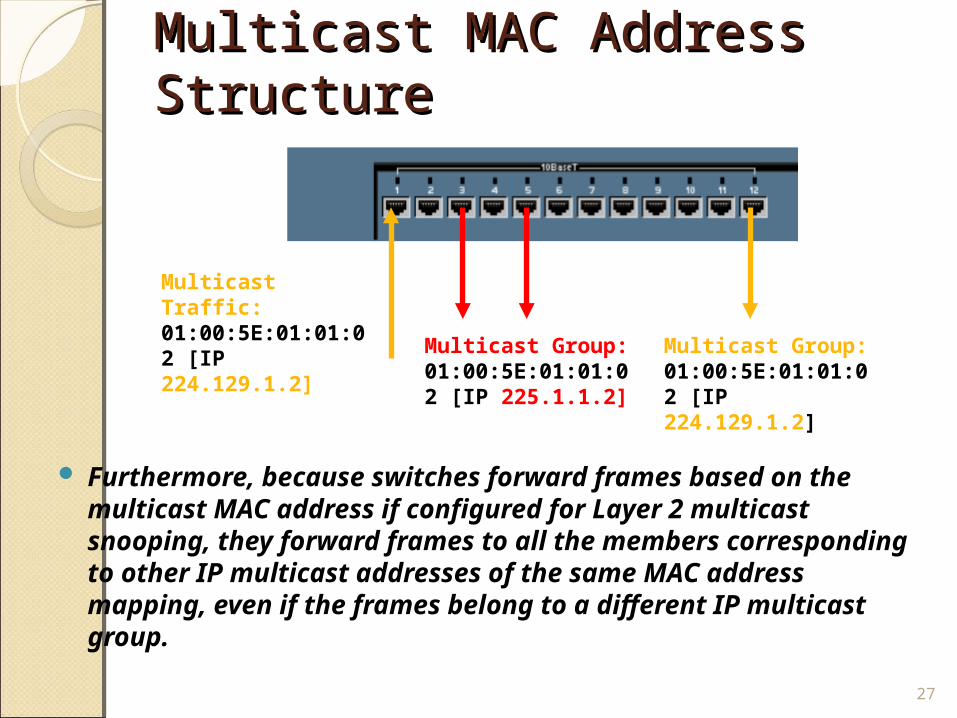
Multicast MAC Address Multicast MAC Address Structure Structure
Furthermore, because switches forward frames based on the multicast MAC address if configured for Layer 2 multicast snooping, they forward frames to all the members corresponding to other IP multicast addresses of the same MAC address mapping, even if the frames belong to a different IP multicast group.
27
Multicast Traffic: 01:00:5E:01:01:02 [IP 224.129.1.2]
Multicast Group: 01:00:5E:01:01:02 [IP 224.129.1.2]
Multicast Group: 01:00:5E:01:01:02 [IP 225.1.1.2]
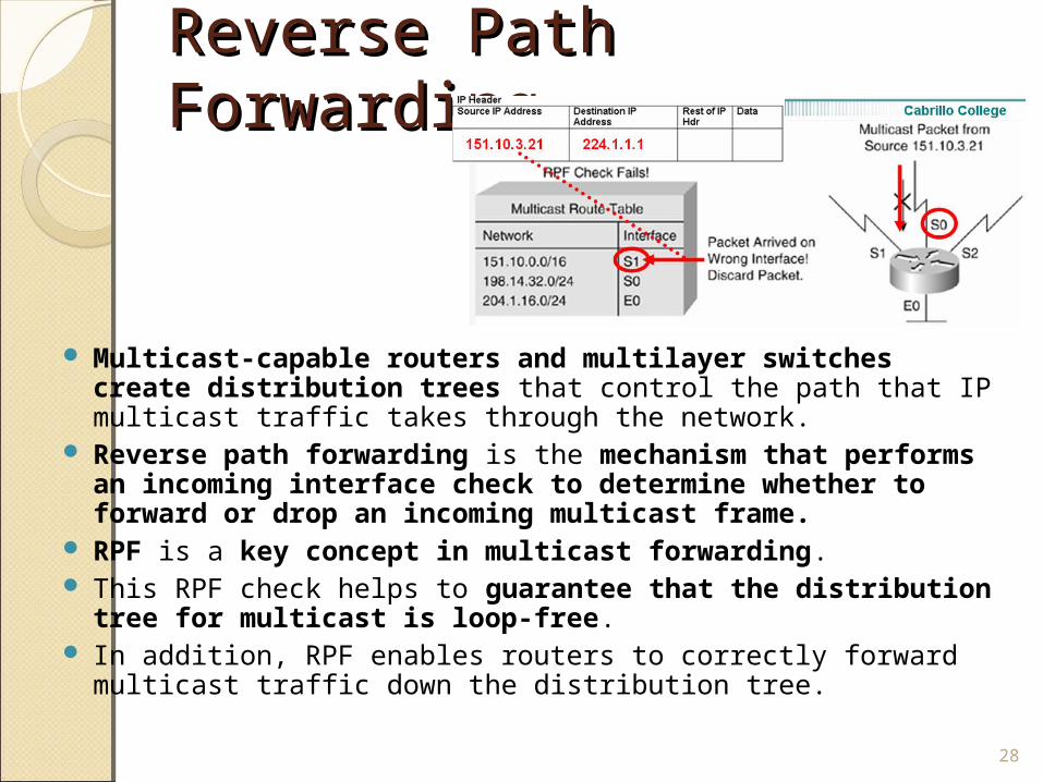
Reverse Path Forwarding Reverse Path Forwarding
Multicast-capable routers and multilayer switches create distribution trees that control the path that IP multicast traffic takes through the network.
Reverse path forwarding is the mechanism that performs an incoming interface check to determine whether to forward or drop an incoming multicast frame.
RPF is a key concept in multicast forwarding. This RPF check helps to guarantee that the distribution
tree for multicast is loop-free. In addition, RPF enables routers to correctly forward multicast
traffic down the distribution tree.28
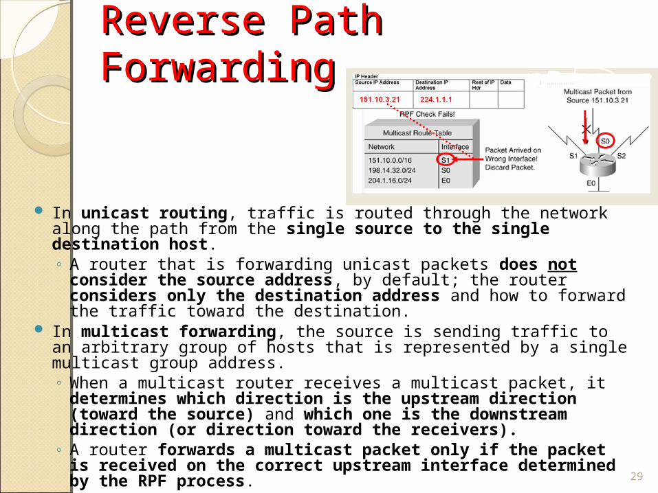
Reverse Path ForwardingReverse Path Forwarding
In unicast routing, traffic is routed through the network along the path from the single source to the single destination host. ◦ A router that is forwarding unicast packets does not consider
the source address, by default; the router considers only the destination address and how to forward the traffic toward the destination.
In multicast forwarding, the source is sending traffic to an arbitrary group of hosts that is represented by a single multicast group address. ◦ When a multicast router receives a multicast packet, it
determines which direction is the upstream direction (toward the source) and which one is the downstream direction (or direction toward the receivers).
◦ A router forwards a multicast packet only if the packet is received on the correct upstream interface determined by the RPF process. 29
Reverse Path Forwarding Reverse Path Forwarding
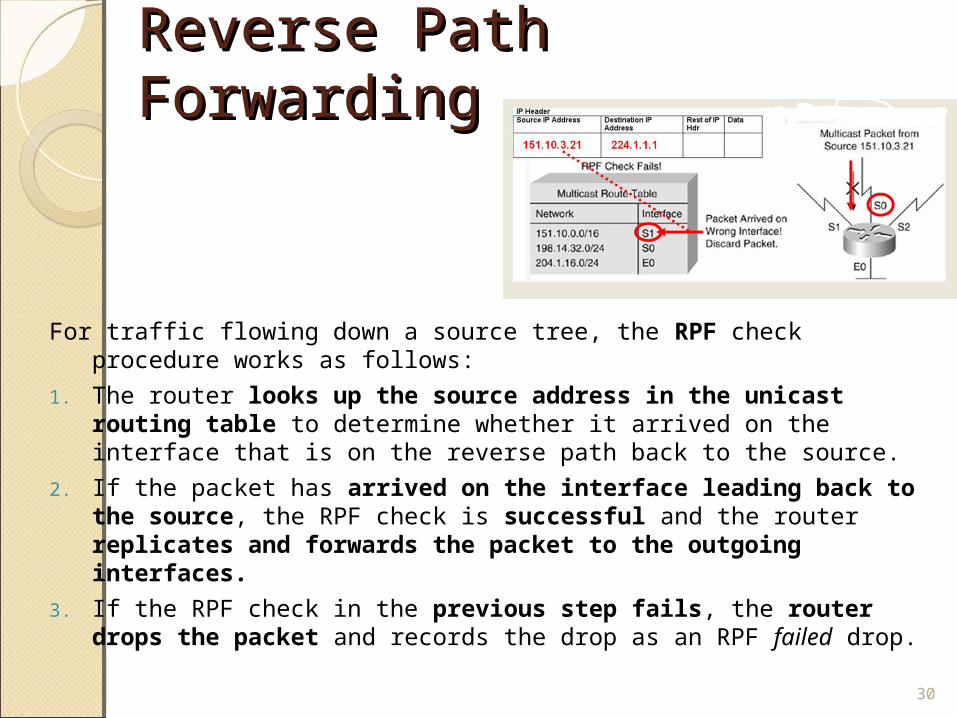
For traffic flowing down a source tree, the RPF check procedure works as follows:
1. The router looks up the source address in the unicast routing table to determine whether it arrived on the interface that is on the reverse path back to the source.
2. If the packet has arrived on the interface leading back to the source, the RPF check is successful and the router replicates and forwards the packet to the outgoing interfaces.
3. If the RPF check in the previous step fails, the router drops the packet and records the drop as an RPF failed drop.
30
RPF check failsRPF check fails
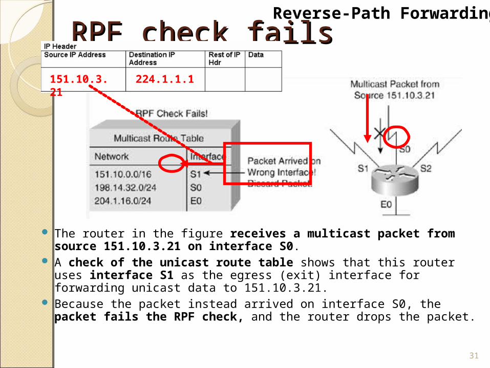
The router in the figure receives a multicast packet from source 151.10.3.21 on interface S0.
A check of the unicast route table shows that this router uses interface S1 as the egress (exit) interface for forwarding unicast data to 151.10.3.21.
Because the packet instead arrived on interface S0, the packet fails the RPF check, and the router drops the packet.
31
151.10.3.21 224.1.1.1
Reverse-Path Forwarding
RPF check succeedsRPF check succeeds
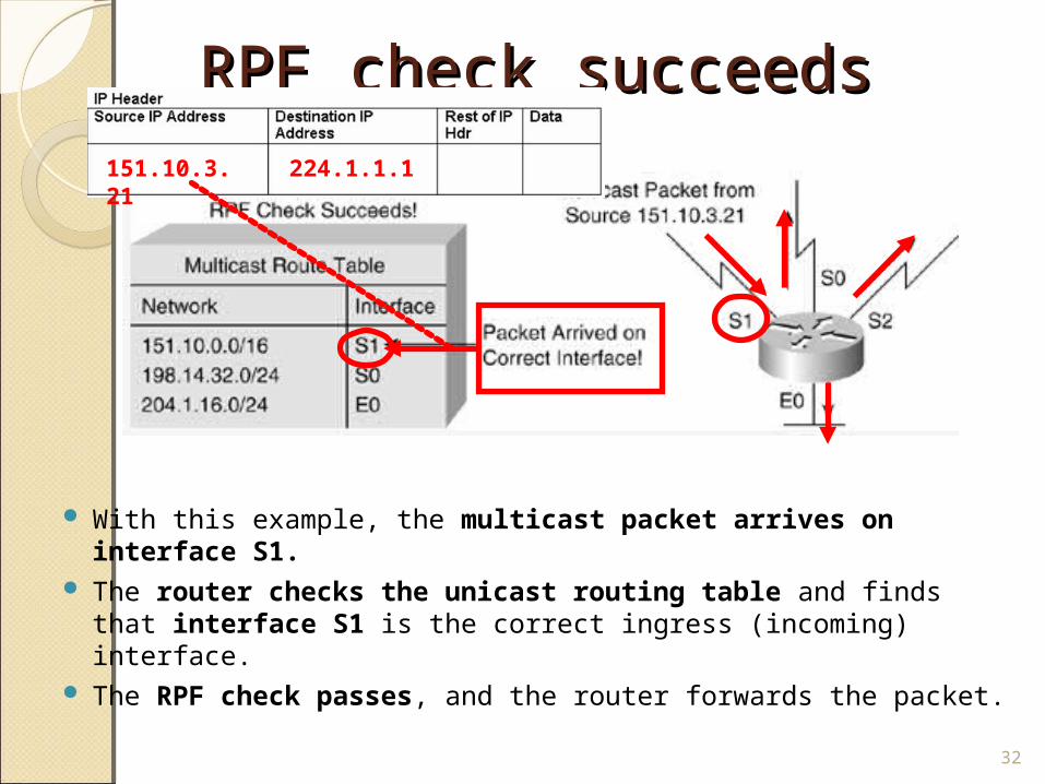
With this example, the multicast packet arrives on interface S1.
The router checks the unicast routing table and finds that interface S1 is the correct ingress (incoming) interface.
The RPF check passes, and the router forwards the packet.
32
151.10.3.21 224.1.1.1
Non-RPF Non-RPF TrafficTraffic
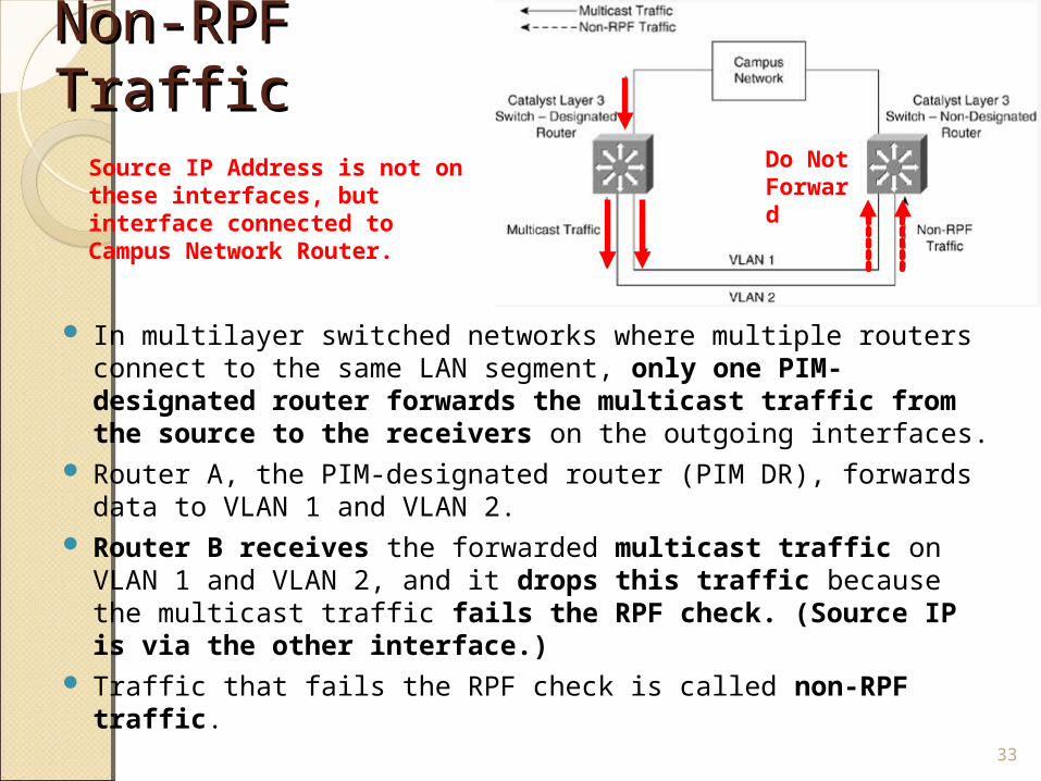
In multilayer switched networks where multiple routers connect to the same LAN segment, only one PIM-designated router forwards the multicast traffic from the source to the receivers on the outgoing interfaces.
Router A, the PIM-designated router (PIM DR), forwards data to VLAN 1 and VLAN 2.
Router B receives the forwarded multicast traffic on VLAN 1 and VLAN 2, and it drops this traffic because the multicast traffic fails the RPF check. (Source IP is via the other interface.)
Traffic that fails the RPF check is called non-RPF traffic.
33
Do Not Forward
Source IP Address is not on these interfaces, but interface connected to Campus Network Router.
Multicast Forwarding Tree Multicast Forwarding Tree
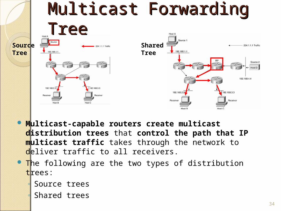
Multicast-capable routers create multicast distribution trees that control the path that IP multicast traffic takes through the network to deliver traffic to all receivers.
The following are the two types of distribution trees:◦ Source trees◦ Shared trees
34
Source Tree
Shared Tree
Source Trees Source Trees
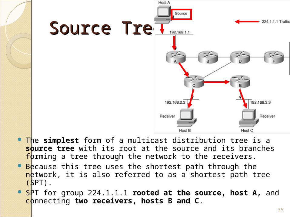
The simplest form of a multicast distribution tree is a source tree with its root at the source and its branches forming a tree through the network to the receivers.
Because this tree uses the shortest path through the network, it is also referred to as a shortest path tree (SPT).
SPT for group 224.1.1.1 rooted at the source, host A, and connecting two receivers, hosts B and C.
35
Source Trees Source Trees
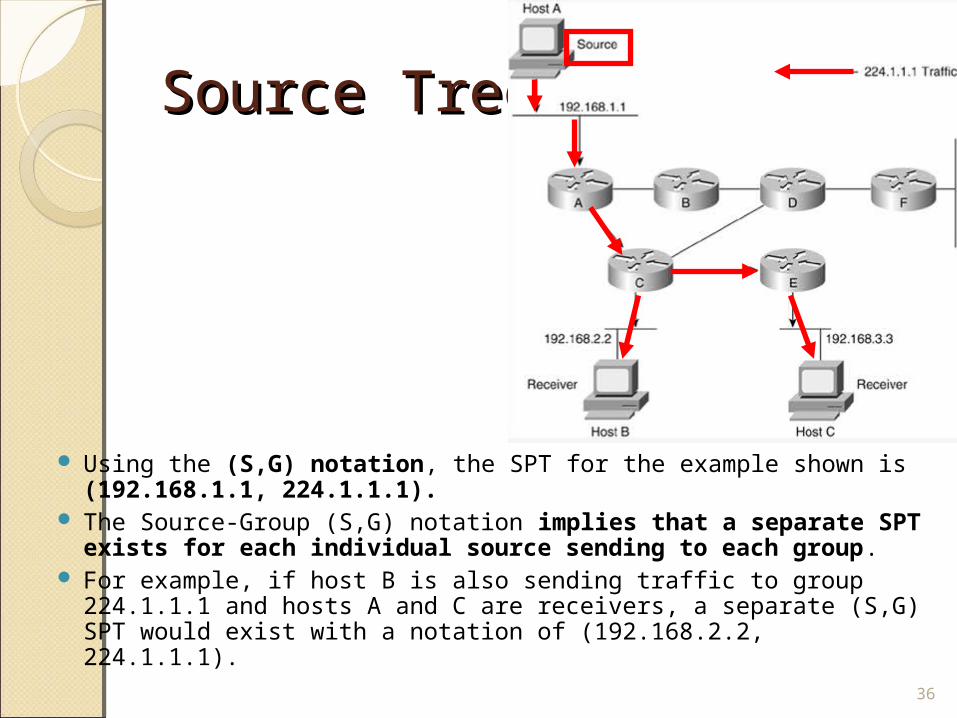
Using the (S,G) notation, the SPT for the example shown is (192.168.1.1, 224.1.1.1).
The Source-Group (S,G) notation implies that a separate SPT exists for each individual source sending to each group.
For example, if host B is also sending traffic to group 224.1.1.1 and hosts A and C are receivers, a separate (S,G) SPT would exist with a notation of (192.168.2.2, 224.1.1.1).
36
Shared Trees Shared Trees
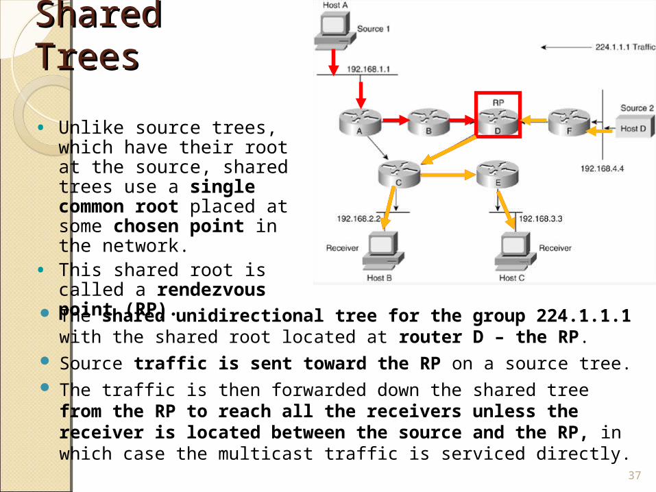
The shared unidirectional tree for the group 224.1.1.1 with the shared root located at router D – the RP.
Source traffic is sent toward the RP on a source tree. The traffic is then forwarded down the shared tree from the
RP to reach all the receivers unless the receiver is located between the source and the RP, in which case the multicast traffic is serviced directly.
37
• Unlike source trees, which have their root at the source, shared trees use a single common root placed at some chosen point in the network.
• This shared root is called a rendezvous point (RP).
Shared Trees Shared Trees
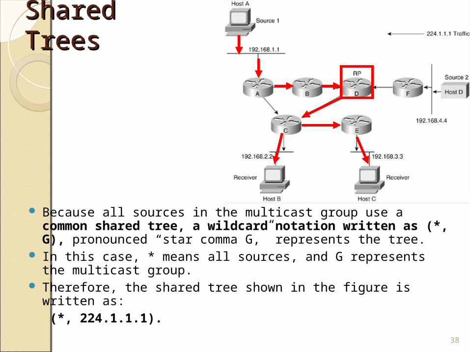
Because all sources in the multicast group use a common shared tree, a wildcard notation written as (*, G), pronounced “star comma G,” represents the tree.
In this case, * means all sources, and G represents the multicast group.
Therefore, the shared tree shown in the figure is written as: (*, 224.1.1.1).
38
Comparing:Comparing:Source TreesSource Trees
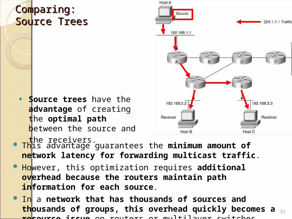
This advantage guarantees the minimum amount of network latency for forwarding multicast traffic.
However, this optimization requires additional overhead because the routers maintain path information for each source.
In a network that has thousands of sources and thousands of groups, this overhead quickly becomes a resource issue on routers or multilayer switches.
39
• Source trees have the advantage of creating the optimal path between the
source and the receivers.
Comparing:Comparing:Shared TreesShared Trees
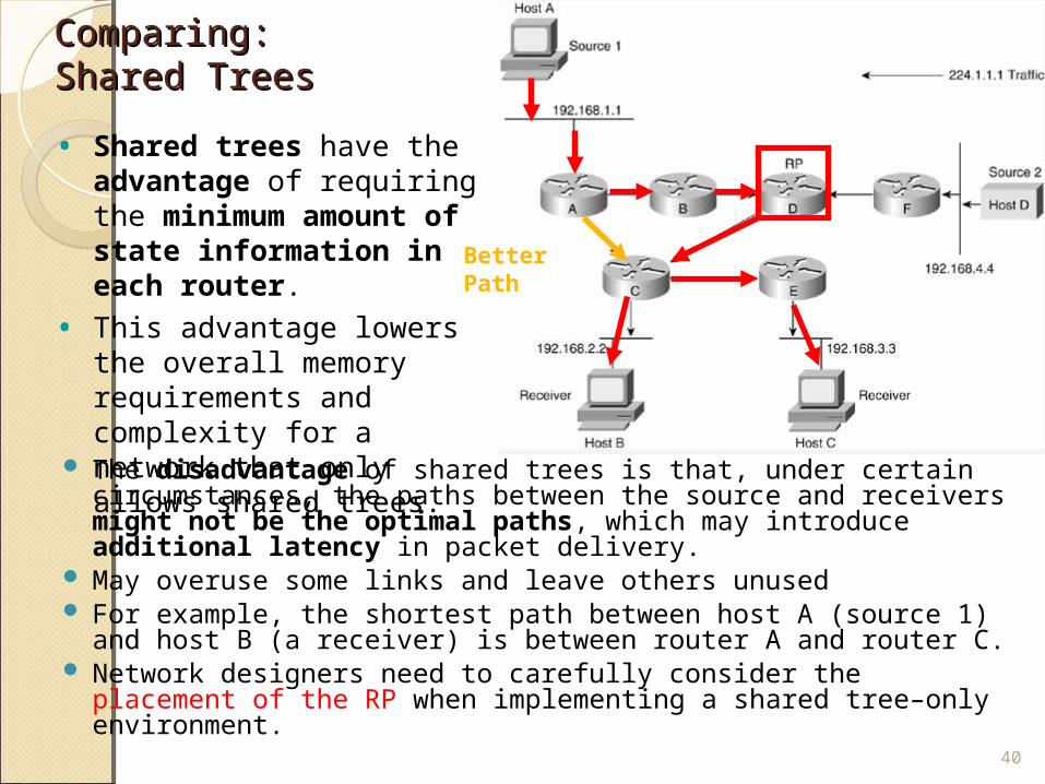
The disadvantage of shared trees is that, under certain circumstances, the paths between the source and receivers might not be the optimal paths, which may introduce additional latency in packet delivery.
May overuse some links and leave others unused For example, the shortest path between host A (source 1) and
host B (a receiver) is between router A and router C. Network designers need to carefully consider the placement
of the RP when implementing a shared tree–only environment. 40
• Shared trees have the advantage of requiring the minimum amount of state information in each router.
• This advantage lowers the overall memory requirements and complexity for a network that only allows shared trees.
Better Path
IP Multicast RoutingIP Multicast Routing
IP Multicast IP Multicast Routing Routing
http://de.wikipedia.org/wiki/Protocol_Independent_Multicast
Similar to IP unicast, IP multicast uses its own routing, management, and Layer 2 protocols.
The following are two important multicast protocols:◦ Protocol Independent Multicast (PIM)
PIM Dense Mode PIM Sparse Mode (Sparse-dense mode is most common in
large enterprise networks.)◦ Internet Group Management Protocol (IGMP)
42
PIM Dense Mode(dicht)
PIM Sparse Mode (spärlich)
PIM PIM
A multicast routing protocol is responsible for the construction of multicast delivery trees and enabling multicast packet forwarding.
Different IP multicast routing protocols use different techniques to construct multicast trees and to forward packets.
The PIM routing protocol leverages whichever unicast routing protocols are used to populate the unicast routing table to make multicast forwarding decisions.
43
PIM Dense Mode
PIM Sparse Mode
PIM PIM
Routers use the PIM neighbor discovery mechanism to establish PIM neighbors using hello messages to the ALL-PIM-Routers (224.0.0.13) multicast address for building and maintaining PIM multicast distribution trees.
In addition, routers use PIM hello messages to elect the designated router (DR) for a multicast LAN network.
Two distinct versions: PIM version 1 and PIM version 2.
44
PIM Dense Mode
PIM Sparse Mode
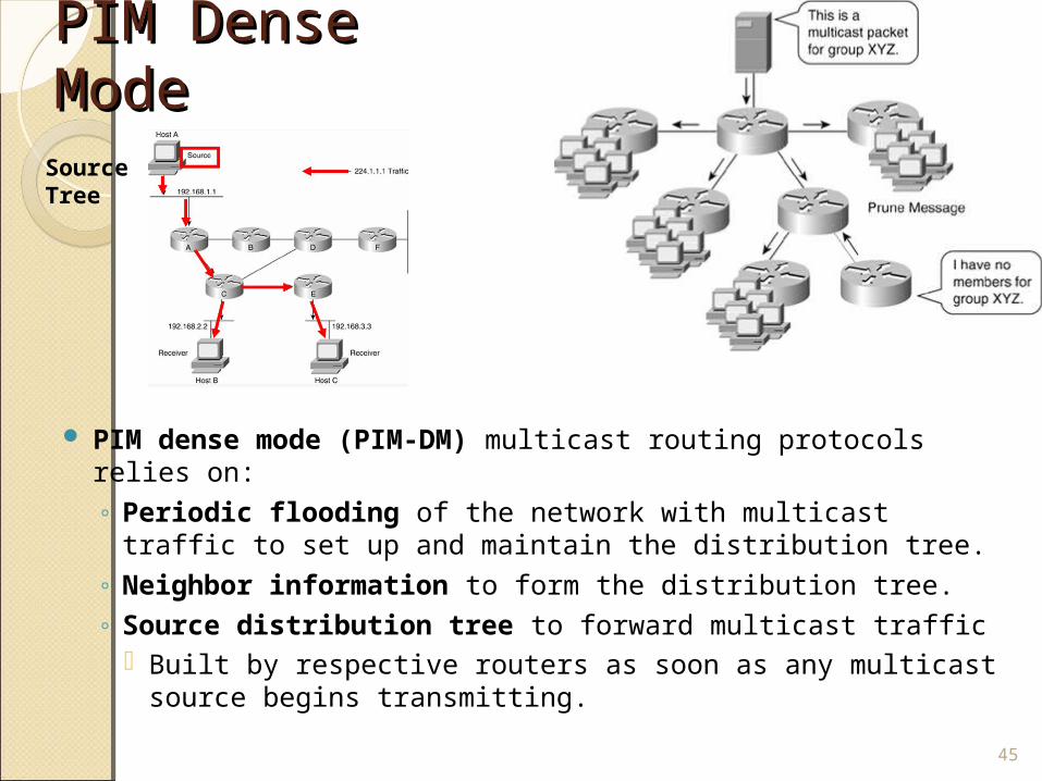
PIM Dense PIM Dense Mode Mode
PIM dense mode (PIM-DM) multicast routing protocols relies on:◦ Periodic flooding of the network with multicast traffic to
set up and maintain the distribution tree. ◦ Neighbor information to form the distribution tree. ◦ Source distribution tree to forward multicast traffic
Built by respective routers as soon as any multicast source begins transmitting.
45
Source Tree
PIM Dense PIM Dense Mode Mode
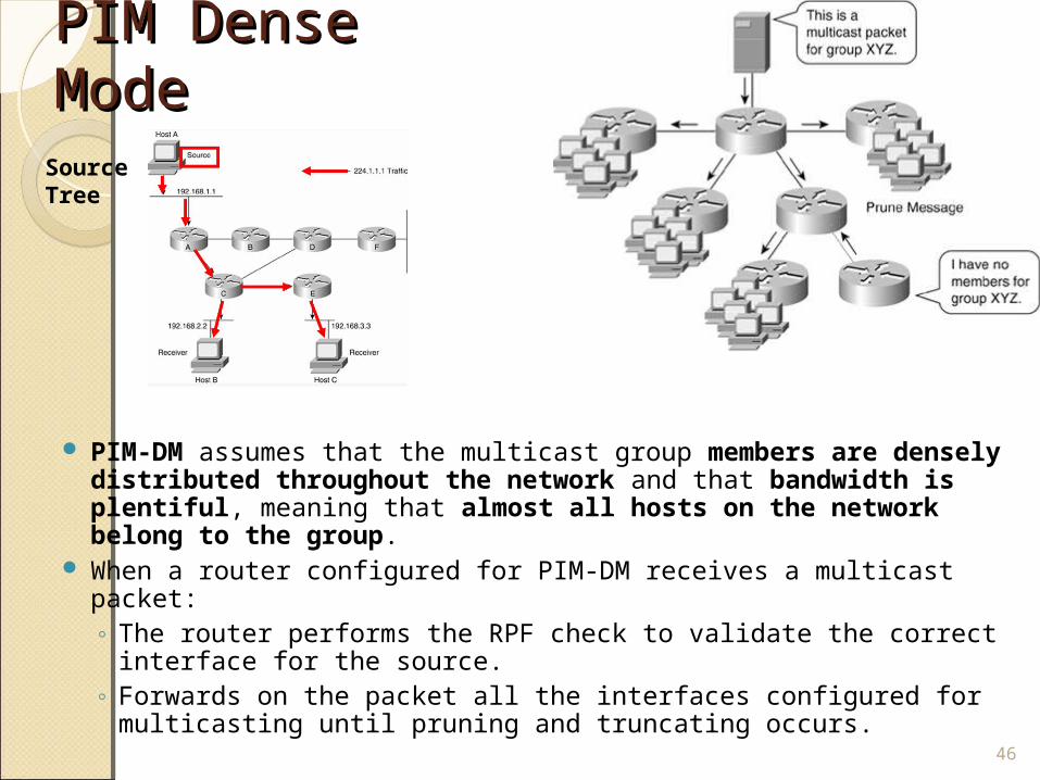
PIM-DM assumes that the multicast group members are densely distributed throughout the network and that bandwidth is plentiful, meaning that almost all hosts on the network belong to the group.
When a router configured for PIM-DM receives a multicast packet:◦ The router performs the RPF check to validate the correct
interface for the source. ◦ Forwards on the packet all the interfaces configured for
multicasting until pruning and truncating occurs.
46
Source Tree
PIM Dense PIM Dense Mode Mode
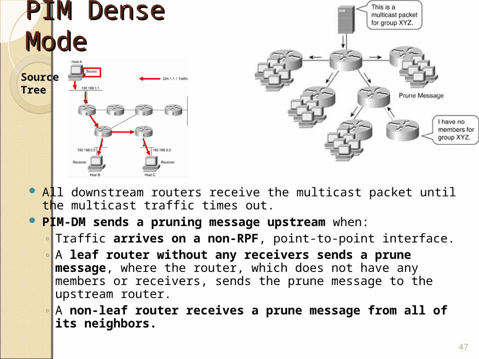
All downstream routers receive the multicast packet until the multicast traffic times out.
PIM-DM sends a pruning message upstream when:◦ Traffic arrives on a non-RPF, point-to-point interface.◦ A leaf router without any receivers sends a prune
message, where the router, which does not have any members or receivers, sends the prune message to the upstream router.
◦ A non-leaf router receives a prune message from all of its neighbors.
47
Source Tree
PIM Dense Mode PIM Dense Mode In summary, PIM-DM works best when numerous members
belong to each multimedia group. PIM floods the multimedia packet to all routers in the network
and then prunes routers that do not service members of that particular multicast group.
PIM-DM is most useful in the following cases:◦ Senders and receivers are in close proximity to one another.◦ There are few senders and many receivers.◦ The volume of multicast traffic is high.◦ The stream of multicast traffic is constant.
Nevertheless, PIM-DM is not the method of choice for enterprise and service provider customers because of its scalability and flooding properties.
48
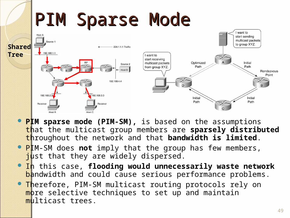
PIM Sparse Mode PIM Sparse Mode
PIM sparse mode (PIM-SM), is based on the assumptions that the multicast group members are sparsely distributed throughout the network and that bandwidth is limited.
PIM-SM does not imply that the group has few members, just that they are widely dispersed.
In this case, flooding would unnecessarily waste network bandwidth and could cause serious performance problems.
Therefore, PIM-SM multicast routing protocols rely on more selective techniques to set up and maintain multicast trees.
49
Shared Tree
PIM Sparse Mode PIM Sparse Mode
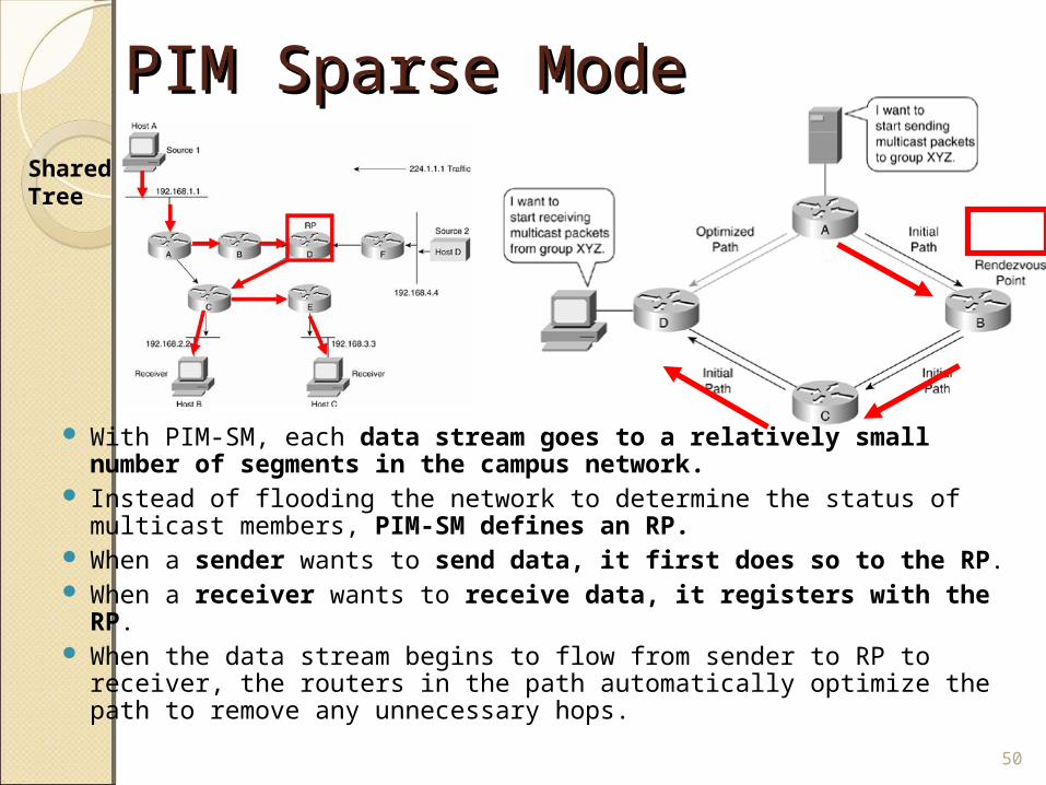
With PIM-SM, each data stream goes to a relatively small number of segments in the campus network.
Instead of flooding the network to determine the status of multicast members, PIM-SM defines an RP.
When a sender wants to send data, it first does so to the RP. When a receiver wants to receive data, it registers with the
RP. When the data stream begins to flow from sender to RP to receiver,
the routers in the path automatically optimize the path to remove any unnecessary hops.
50
Shared Tree
PIM Sparse Mode PIM Sparse Mode
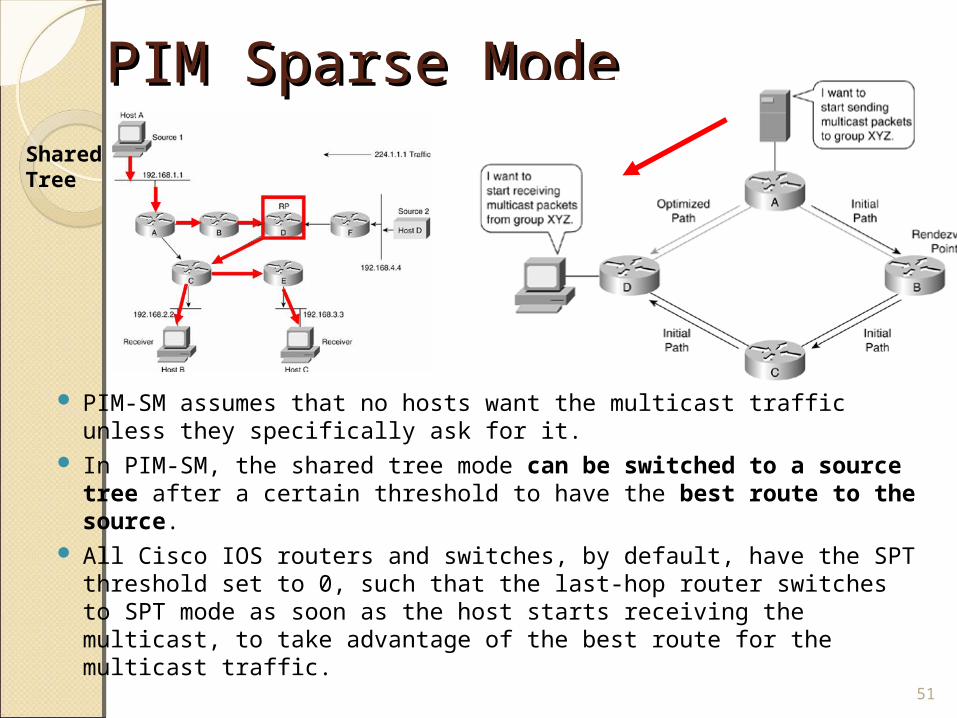
PIM-SM assumes that no hosts want the multicast traffic unless they specifically ask for it.
In PIM-SM, the shared tree mode can be switched to a source tree after a certain threshold to have the best route to the source.
All Cisco IOS routers and switches, by default, have the SPT threshold set to 0, such that the last-hop router switches to SPT mode as soon as the host starts receiving the multicast, to take advantage of the best route for the multicast traffic.
51
Shared Tree
PIM Sparse Mode PIM Sparse Mode
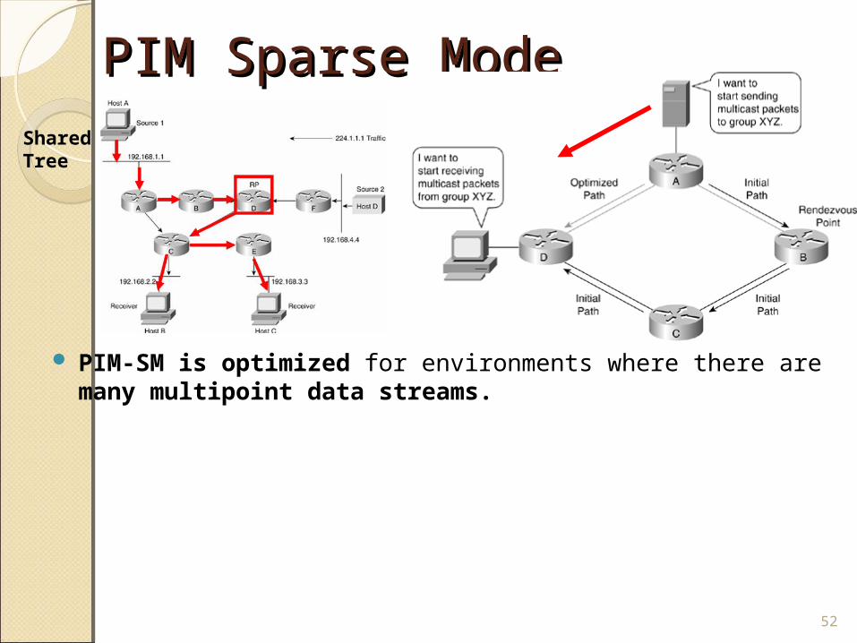
PIM-SM is optimized for environments where there are many multipoint data streams.
52
Shared Tree
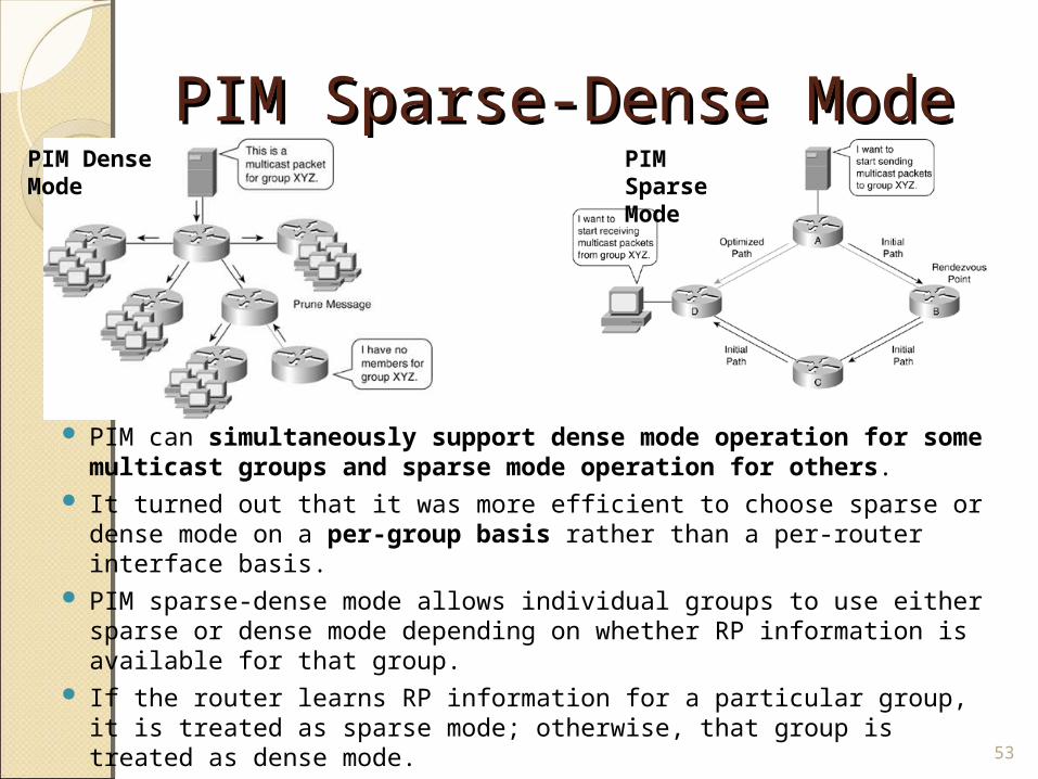
PIM Sparse-Dense Mode PIM Sparse-Dense Mode
PIM can simultaneously support dense mode operation for some multicast groups and sparse mode operation for others.
It turned out that it was more efficient to choose sparse or dense mode on a per-group basis rather than a per-router interface basis.
PIM sparse-dense mode allows individual groups to use either sparse or dense mode depending on whether RP information is available for that group.
If the router learns RP information for a particular group, it is treated as sparse mode; otherwise, that group is treated as dense mode.
53
PIM Dense Mode
PIM Sparse Mode
Automating Distribution of Automating Distribution of RP RP
PIM-SM and PIM sparse-dense modes use various methods, discussed in this section, to automate the distribution of the RP.
This mechanism has the following benefits:◦ It eliminates the need to manually configure RP information in
every router and switch in the network.◦ It is easy to use multiple RPs within a network to serve different group
ranges.◦ It allows load-splitting among different RPs and allows the arrangement
of RPs according to the location of group participants.◦ It avoids inconsistency; manual RP configurations may cause
connectivity problems, if not configured properly. PIM uses the following mechanisms to automate the distribution of the
RP:◦ Auto-RP◦ Bo◦ Auto-RP is a Cisco proprietary protocol for automatically advertising RP-
to-group mappings to routers in your PIM network.otstrap router (BSR)
54
Auto-Auto-RP RP
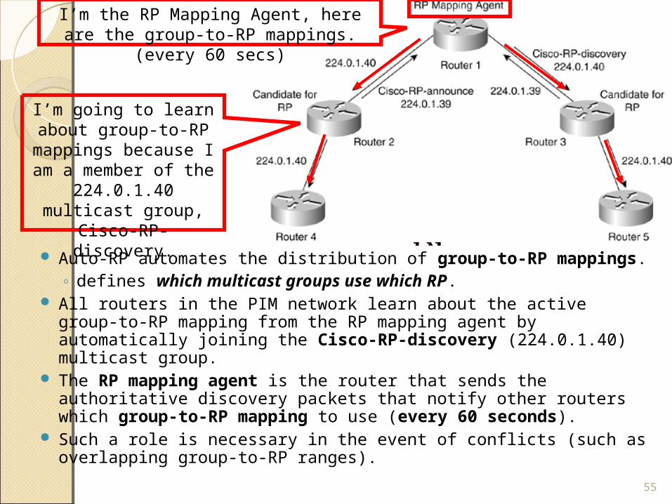
Auto-RP automates the distribution of group-to-RP mappings. ◦ defines which multicast groups use which RP.
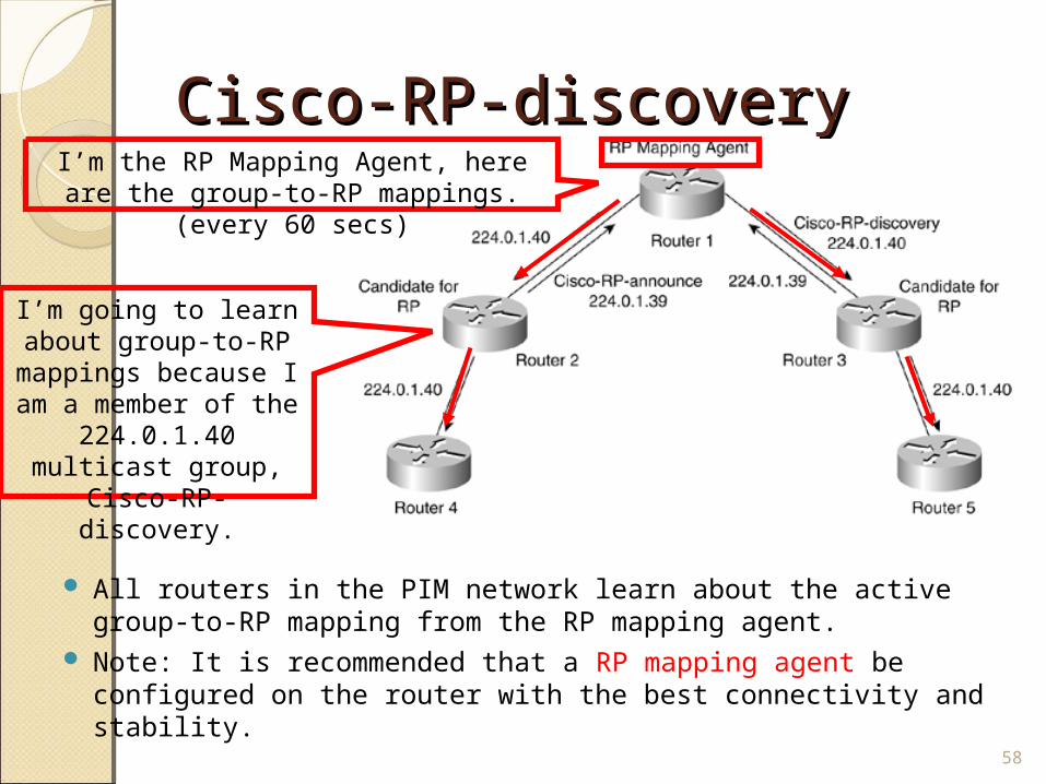
All routers in the PIM network learn about the active group-to-RP mapping from the RP mapping agent by automatically joining the Cisco-RP-discovery (224.0.1.40) multicast group.
The RP mapping agent is the router that sends the authoritative discovery packets that notify other routers which group-to-RP mapping to use (every 60 seconds).
Such a role is necessary in the event of conflicts (such as overlapping group-to-RP ranges).
55
I’m going to learn about group-to-RP mappings
because I am a member of the 224.0.1.40
multicast group, Cisco-RP-discovery.
I’m the RP Mapping Agent, here are the group-to-RP mappings. (every 60 secs)
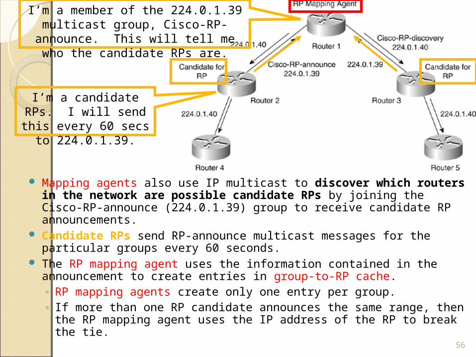
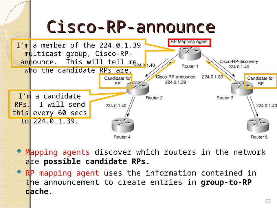
Mapping agents also use IP multicast to discover which routers in the network are possible candidate RPs by joining the Cisco-RP-announce (224.0.1.39) group to receive candidate RP announcements.
Candidate RPs send RP-announce multicast messages for the particular groups every 60 seconds.
The RP mapping agent uses the information contained in the announcement to create entries in group-to-RP cache. ◦ RP mapping agents create only one entry per group. ◦ If more than one RP candidate announces the same range, then the
RP mapping agent uses the IP address of the RP to break the tie.
56
I’m a member of the 224.0.1.39 multicast group, Cisco-RP-announce. This will tell
me who the candidate RPs are.
I’m a candidate RPs. I will send this every 60
secs to 224.0.1.39.
Cisco-RP-announce Cisco-RP-announce
Mapping agents discover which routers in the network are possible candidate RPs.
RP mapping agent uses the information contained in the announcement to create entries in group-to-RP cache.
57
I’m a member of the 224.0.1.39 multicast group, Cisco-RP-announce. This will tell
me who the candidate RPs are.
I’m a candidate RPs. I will send this every 60
secs to 224.0.1.39.
Cisco-RP-discoveryCisco-RP-discovery
All routers in the PIM network learn about the active group-to-RP mapping from the RP mapping agent.
Note: It is recommended that a RP mapping agent be configured on the router with the best connectivity and stability.
58
Auto-RP
I’m going to learn about group-to-RP mappings
because I am a member of the 224.0.1.40
multicast group, Cisco-RP-discovery.
I’m the RP Mapping Agent, here are the group-to-RP mappings. (every 60 secs)
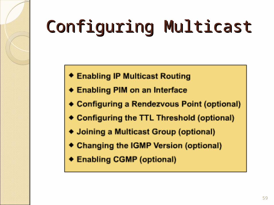
Configuring MulticastConfiguring Multicast
59
Configuring PIM DM/SMConfiguring PIM DM/SM
First, enable multicast routing (disabled by default):Router(config)#ip multicast-
routing
Next, enable PIM on an interface. It is best to enable PIM on every
interface in every router in the network, using the following interface command:
Router(config-if)#ip pim {dense-mode | sparse mode | sparse-
dense-mode}
60
Configuring PIM DM/SMConfiguring PIM DM/SM The recommended method for enabling multicast on
an interface is the use of the ip pim sparse-dense-mode command.
This command allows the router to use either dense or sparse mode, depending on the existence of RP information for each multicast group. ◦ This makes it much easier to switch the entire
network from dense mode to sparse mode (or vice versa) as needed.
61
Configuring PIM DM/SMConfiguring PIM DM/SM
PIM SM only:• Because PIM SM uses a shared tree, you must also specify
the rendezvous point address.• The RP doesn’t need to know it is the RP.• A PIM router can be an RP for more than one group.• To designate the RP on a leaf router:
Router(config)#ip pim rp-address <address>
62
Bootstrap Bootstrap Router Router
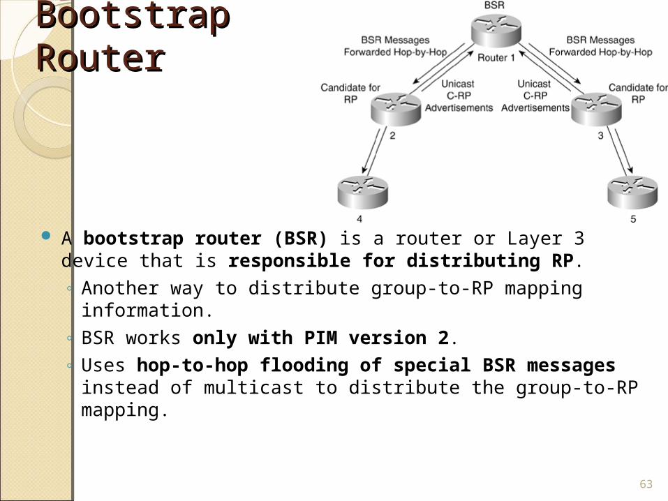
A bootstrap router (BSR) is a router or Layer 3 device that is responsible for distributing RP. ◦ Another way to distribute group-to-RP mapping information. ◦ BSR works only with PIM version 2. ◦ Uses hop-to-hop flooding of special BSR messages
instead of multicast to distribute the group-to-RP mapping.
63
BSR ElectionBSR Election
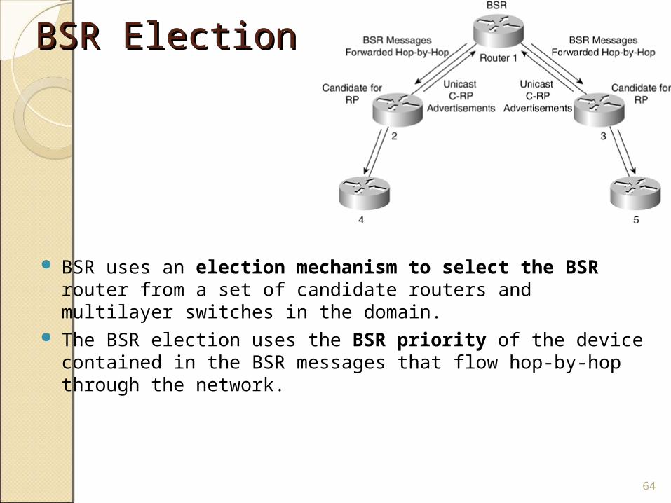
BSR uses an election mechanism to select the BSR router from a set of candidate routers and multilayer switches in the domain.
The BSR election uses the BSR priority of the device contained in the BSR messages that flow hop-by-hop through the network.
64
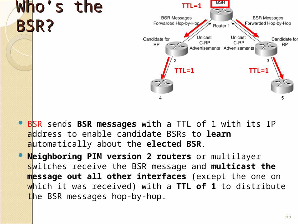
Who’s the Who’s the BSR?BSR?
BSR sends BSR messages with a TTL of 1 with its IP address to enable candidate BSRs to learn automatically about the elected BSR.
Neighboring PIM version 2 routers or multilayer switches receive the BSR message and multicast the message out all other interfaces (except the one on which it was received) with a TTL of 1 to distribute the BSR messages hop-by-hop.
65
TTL=1
TTL=1 TTL=1
Candidate Candidate RPsRPs
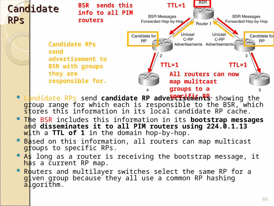
Candidate RPs send candidate RP advertisements showing the group range for which each is responsible to the BSR, which stores this information in its local candidate RP cache.
The BSR includes this information in its bootstrap messages and disseminates it to all PIM routers using 224.0.1.13 with a TTL of 1 in the domain hop-by-hop.
Based on this information, all routers can map multicast groups to specific RPs.
As long as a router is receiving the bootstrap message, it has a current RP map.
Routers and multilayer switches select the same RP for a given group because they all use a common RP hashing algorithm.
66
TTL=1
TTL=1 TTL=1
Candidate RPs send advertisement to BSR with groups they are responsible for.
BSR sends this info to all PIM routers
All routers can now map mulitcast groups to a specific RP.
Comparison and Compatibility of PIM Comparison and Compatibility of PIM Version 1 and Version 2 Version 1 and Version 2
PIM version 2 is a standards-based multicast protocol in the Internet Engineering Task Force (IETF).
Cisco highly recommends using PIM version 2 in the entire multilayer switched network.
Cisco's PIM version 2 implementation allows interoperability and transition between version 1 and version 2, although there are a few caveats.
67
IGMP - Internet Group Management IGMP - Internet Group Management ProtocolProtocol
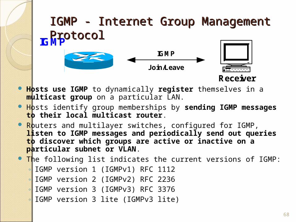
Hosts use IGMP to dynamically register themselves in a multicast group on a particular LAN.
Hosts identify group memberships by sending IGMP messages to their local multicast router.
Routers and multilayer switches, configured for IGMP, listen to IGMP messages and periodically send out queries to discover which groups are active or inactive on a particular subnet or VLAN.
The following list indicates the current versions of IGMP:◦ IGMP version 1 (IGMPv1) RFC 1112◦ IGMP version 2 (IGMPv2) RFC 2236◦ IGMP version 3 (IGMPv3) RFC 3376◦ IGMP version 3 lite (IGMPv3 lite)
68
ReceiverJoin/Leave
IGMP
IGMP
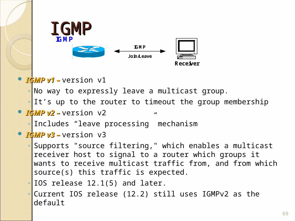
IGMPIGMP
IGMP v1 – IGMP v1 – version v1 ◦ No way to expressly leave a multicast group. ◦ It’s up to the router to timeout the group membership
IGMP v2 – IGMP v2 – version v2 ◦ Includes “leave processing” mechanism
IGMP v3 – IGMP v3 – version v3 ◦ Supports "source filtering," which enables a multicast
receiver host to signal to a router which groups it wants to receive multicast traffic from, and from which source(s) this traffic is expected.
◦ IOS release 12.1(5) and later.◦ Current IOS release (12.2) still uses IGMPv2 as the default
69
ReceiverJoin/Leave
IGMP
IGMP
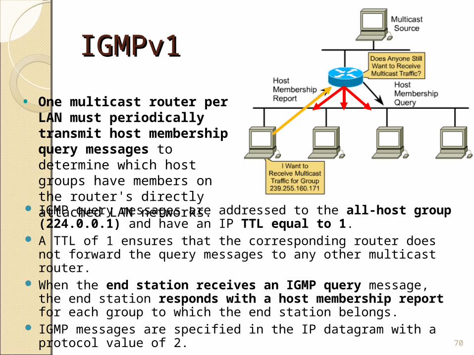
IGMPv1 IGMPv1
IGMP query messages are addressed to the all-host group (224.0.0.1) and have an IP TTL equal to 1.
A TTL of 1 ensures that the corresponding router does not forward the query messages to any other multicast router.
When the end station receives an IGMP query message, the end station responds with a host membership report for each group to which the end station belongs.
IGMP messages are specified in the IP datagram with a protocol value of 2.
70
• One multicast router per LAN must periodically transmit host membership query messages to determine which host groups have members on the router's directly attached LAN networks.
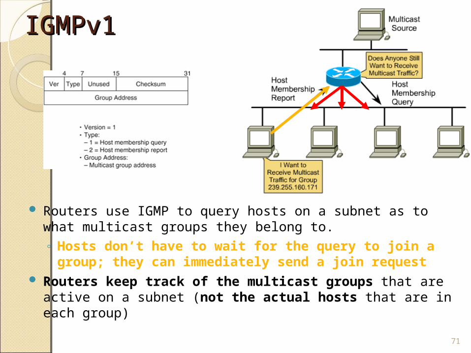
IGMPv1 IGMPv1
Routers use IGMP to query hosts on a subnet as to what multicast groups they belong to.◦ Hosts don’t have to wait for the query to join a
group; they can immediately send a join request Routers keep track of the multicast groups that are
active on a subnet (not the actual hosts that are in each group)
71
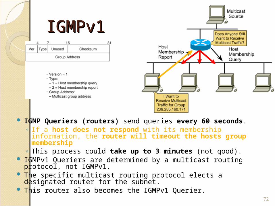
IGMPv1IGMPv1
IGMP Queriers (routers) send queries every 60 seconds.◦ If a host does not respond with its membership information,
the router will timeout the hosts group membership◦ This process could take up to 3 minutes (not good).
IGMPv1 Queriers are determined by a multicast routing protocol, not IGMPv1.
The specific multicast routing protocol elects a designated router for the subnet.
This router also becomes the IGMPv1 Querier.
72
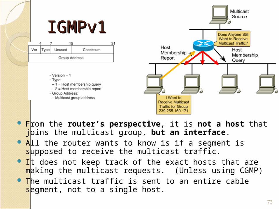
IGMPv1IGMPv1
From the router’s perspective, it is not a host that joins the multicast group, but an interface.
All the router wants to know is if a segment is supposed to receive the multicast traffic.
It does not keep track of the exact hosts that are making the multicast requests. (Unless using CGMP)
The multicast traffic is sent to an entire cable segment, not to a single host.
73
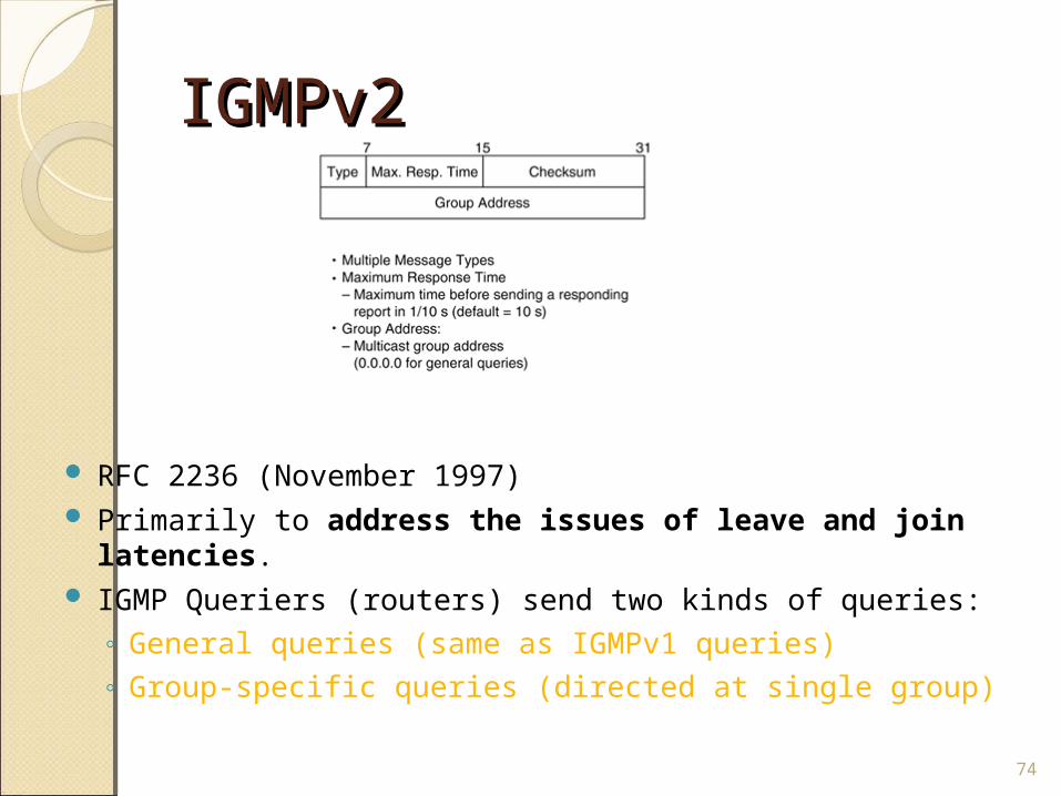
IGMPv2 IGMPv2
RFC 2236 (November 1997) Primarily to address the issues of leave and join
latencies. IGMP Queriers (routers) send two kinds of queries:
◦ General queries (same as IGMPv1 queries)◦ Group-specific queries (directed at single group)
74
IGMPv2 - JoinIGMPv2 - Join
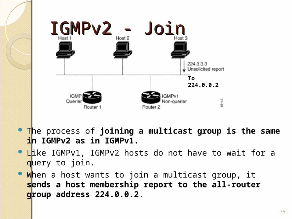
The process of joining a multicast group is the same in IGMPv2 as in IGMPv1.
Like IGMPv1, IGMPv2 hosts do not have to wait for a query to join.
When a host wants to join a multicast group, it sends a host membership report to the all-router group address 224.0.0.2.
75
To 224.0.0.2
IGMPv2 - JoinIGMPv2 - Join
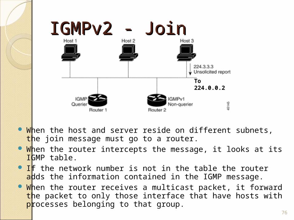
When the host and server reside on different subnets, the join message must go to a router.
When the router intercepts the message, it looks at its IGMP table.
If the network number is not in the table the router adds the information contained in the IGMP message.
When the router receives a multicast packet, it forward the packet to only those interface that have hosts with processes belonging to that group.
76
To 224.0.0.2
IGMPv2 - JoinIGMPv2 - Join
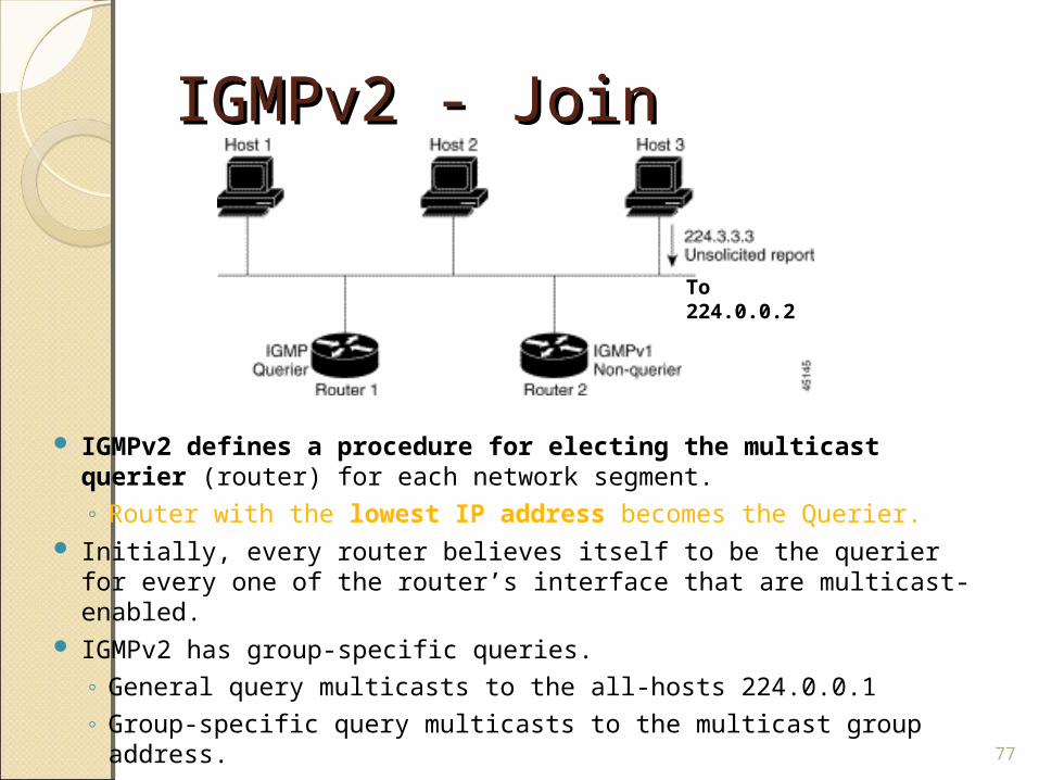
IGMPv2 defines a procedure for electing the multicast querier (router) for each network segment.◦ Router with the lowest IP address becomes the Querier.
Initially, every router believes itself to be the querier for every one of the router’s interface that are multicast-enabled.
IGMPv2 has group-specific queries.◦ General query multicasts to the all-hosts 224.0.0.1◦ Group-specific query multicasts to the multicast group
address. 77
To 224.0.0.2
IGMPv2 - JoinIGMPv2 - Join
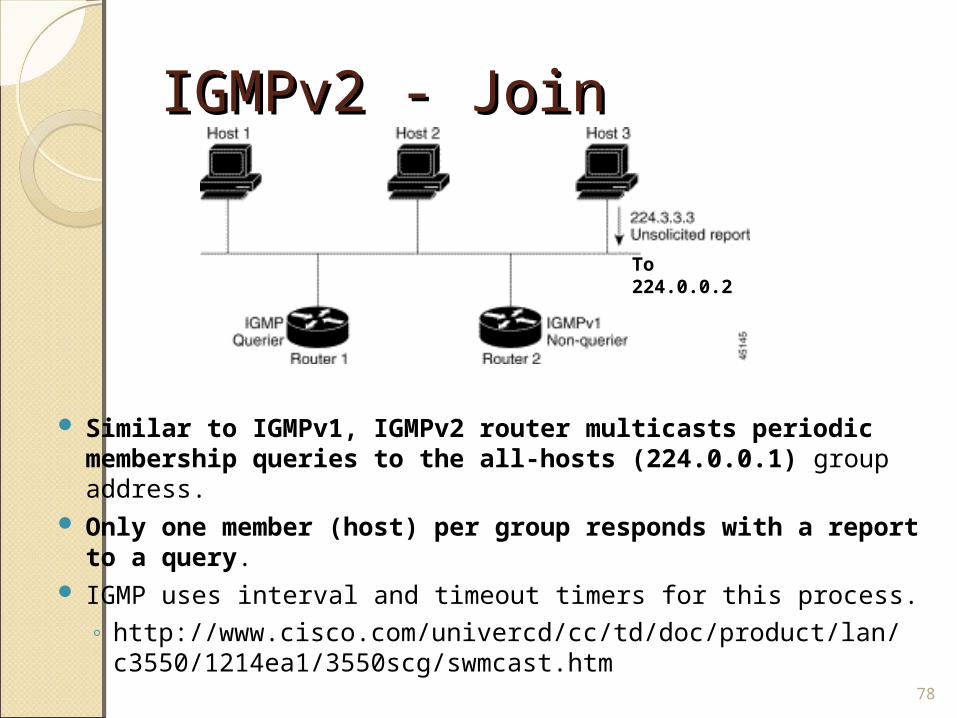
Similar to IGMPv1, IGMPv2 router multicasts periodic membership queries to the all-hosts (224.0.0.1) group address.
Only one member (host) per group responds with a report to a query.
IGMP uses interval and timeout timers for this process.◦ http://www.cisco.com/univercd/cc/td/doc/product/lan/
c3550/1214ea1/3550scg/swmcast.htm78
To 224.0.0.2
IGMPv2 - LeaveIGMPv2 - Leave
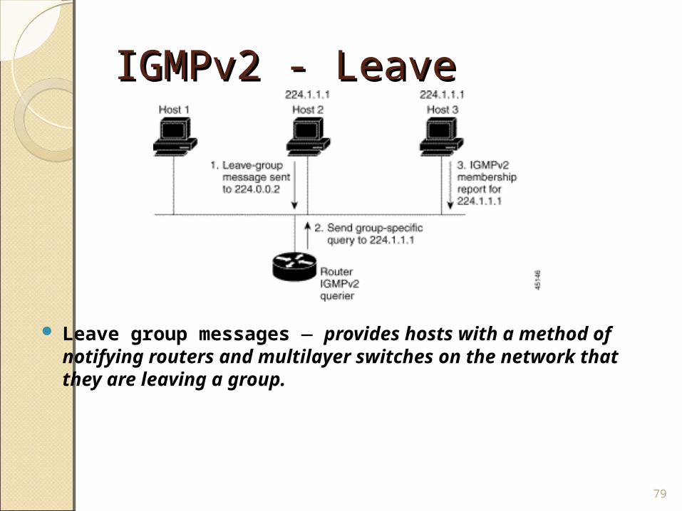
Leave group messages — provides hosts with a method of notifying routers and multilayer switches on the network that they are leaving a group.
79
IGMPv2 - IGMPv2 - LeaveLeave
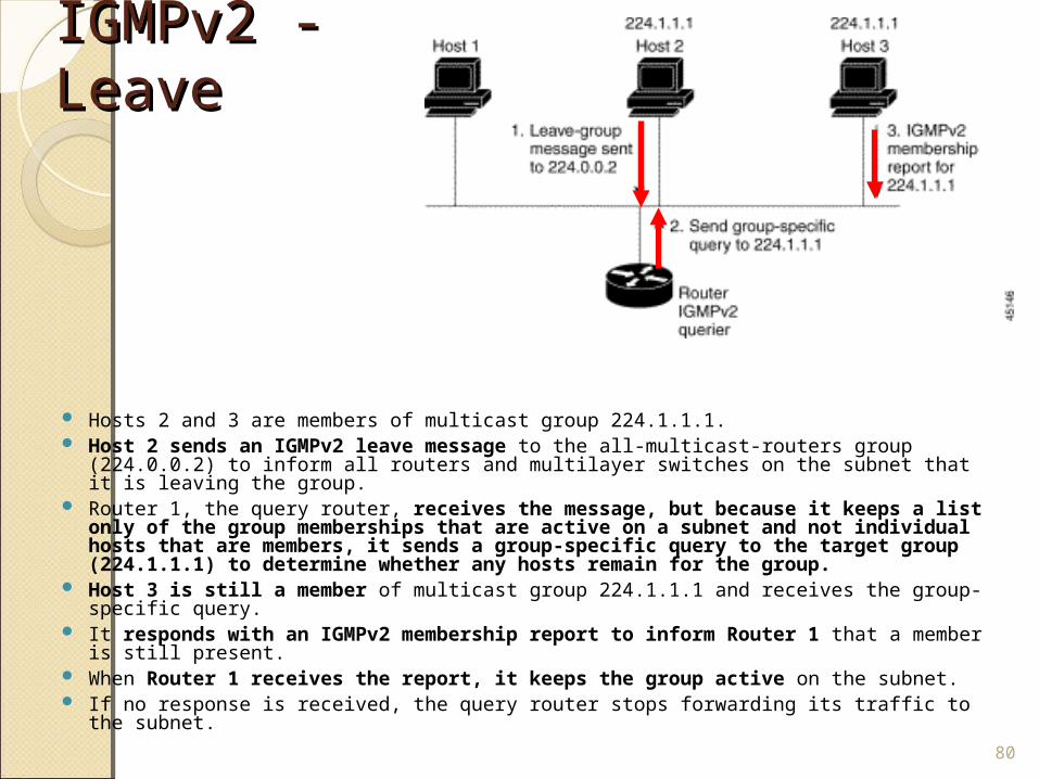
Hosts 2 and 3 are members of multicast group 224.1.1.1. Host 2 sends an IGMPv2 leave message to the all-multicast-routers group
(224.0.0.2) to inform all routers and multilayer switches on the subnet that it is leaving the group.
Router 1, the query router, receives the message, but because it keeps a list only of the group memberships that are active on a subnet and not individual hosts that are members, it sends a group-specific query to the target group (224.1.1.1) to determine whether any hosts remain for the group.
Host 3 is still a member of multicast group 224.1.1.1 and receives the group-specific query.
It responds with an IGMPv2 membership report to inform Router 1 that a member is still present.
When Router 1 receives the report, it keeps the group active on the subnet. If no response is received, the query router stops forwarding its traffic to the subnet.
80
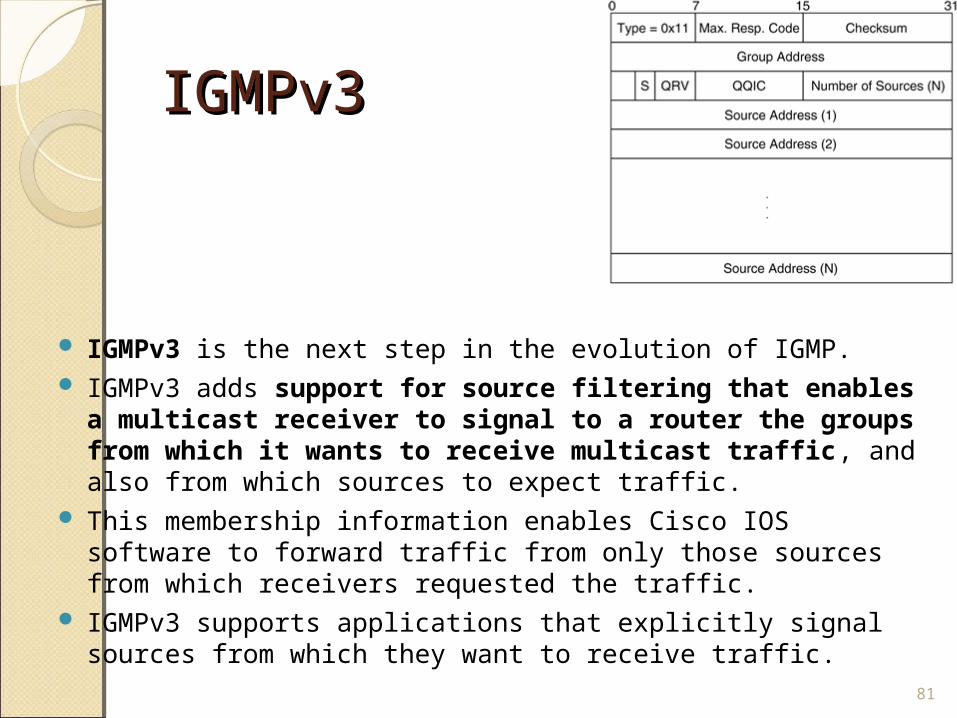
IGMPv3 IGMPv3
IGMPv3 is the next step in the evolution of IGMP. IGMPv3 adds support for source filtering that enables a
multicast receiver to signal to a router the groups from which it wants to receive multicast traffic, and also from which sources to expect traffic.
This membership information enables Cisco IOS software to forward traffic from only those sources from which receivers requested the traffic.
IGMPv3 supports applications that explicitly signal sources from which they want to receive traffic.
81
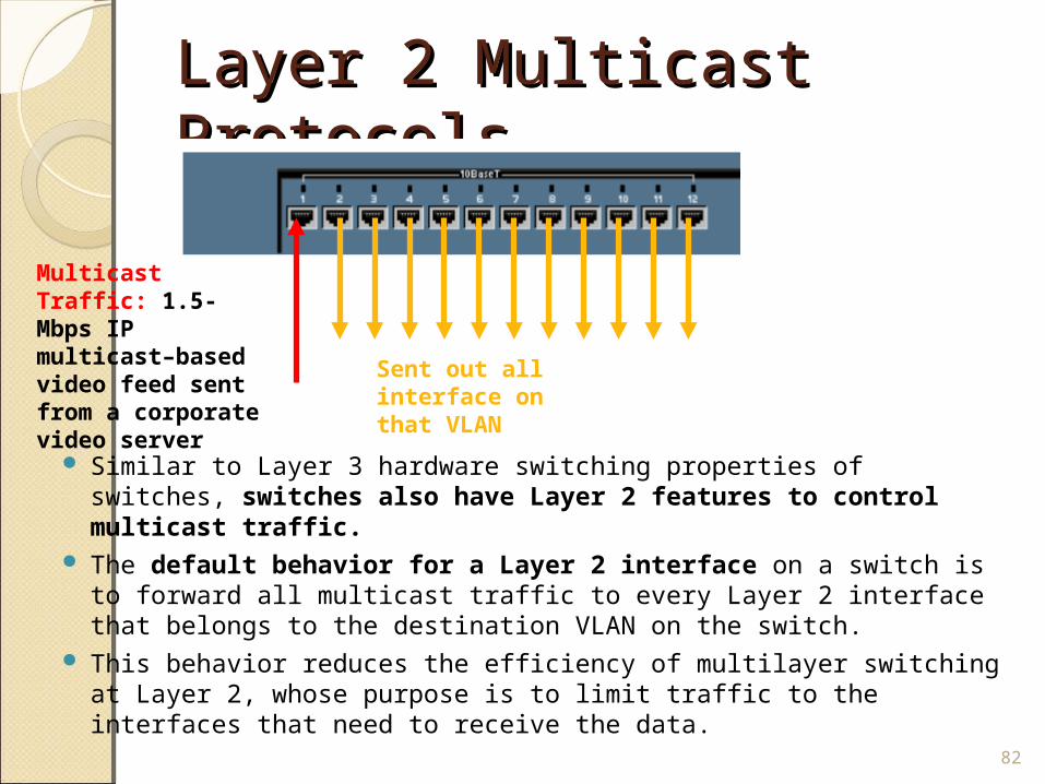
Layer 2 Multicast Layer 2 Multicast Protocols Protocols
Similar to Layer 3 hardware switching properties of switches, switches also have Layer 2 features to control multicast traffic.
The default behavior for a Layer 2 interface on a switch is to forward all multicast traffic to every Layer 2 interface that belongs to the destination VLAN on the switch.
This behavior reduces the efficiency of multilayer switching at Layer 2, whose purpose is to limit traffic to the interfaces that need to receive the data.
82
Multicast Traffic: 1.5-Mbps IP multicast–based video feed sent from a corporate video server
Sent out all interface on that VLAN
Layer 2 Multicast Layer 2 Multicast Protocols Protocols
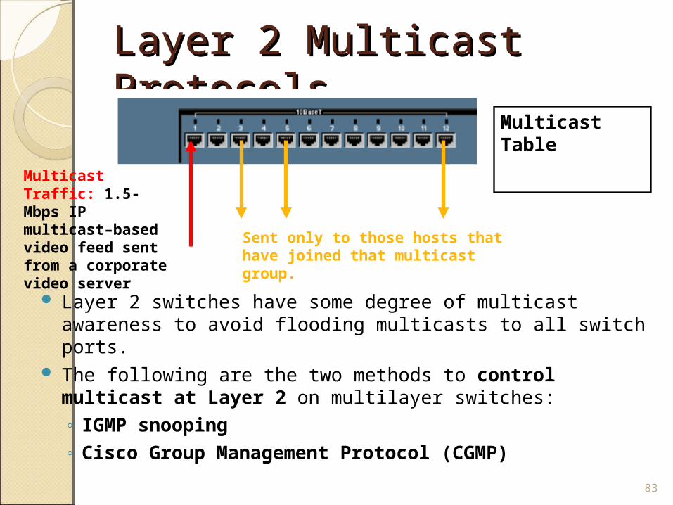
Layer 2 switches have some degree of multicast awareness to avoid flooding multicasts to all switch ports.
The following are the two methods to control multicast at Layer 2 on multilayer switches:◦ IGMP snooping◦ Cisco Group Management Protocol (CGMP)
83
Multicast Traffic: 1.5-Mbps IP multicast–based video feed sent from a corporate video server
Sent only to those hosts that have joined that multicast group.
Multicast Table
IGMP IGMP SnoopingSnooping
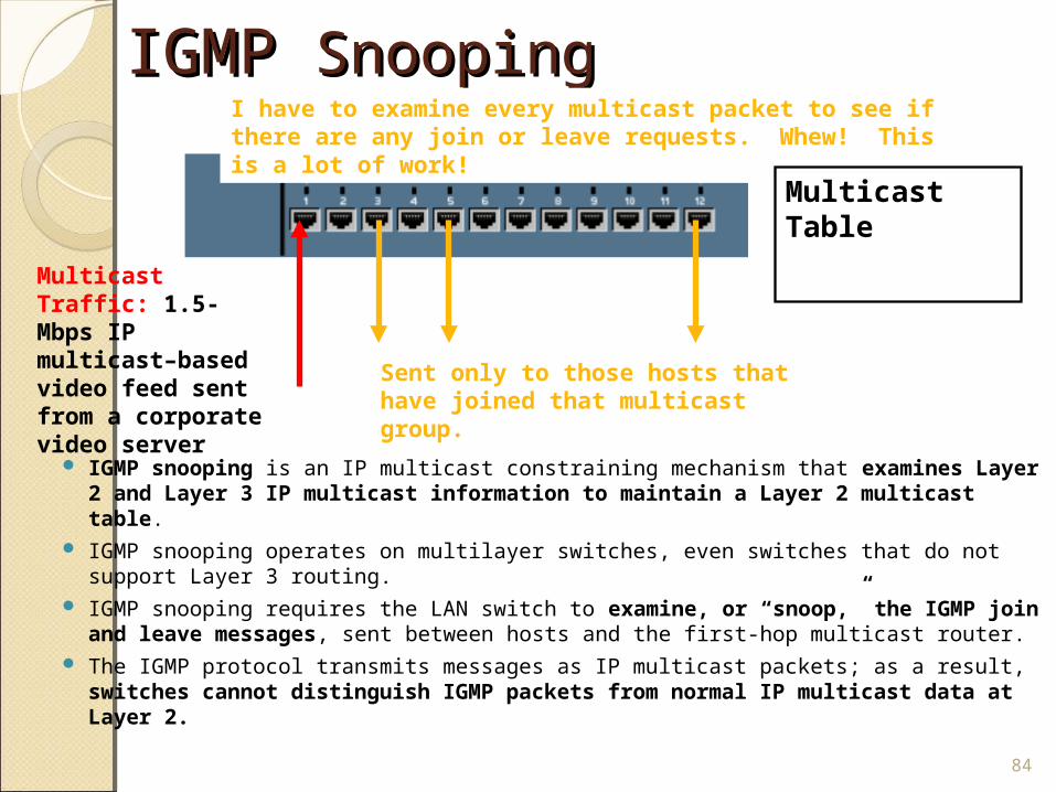
IGMP snooping is an IP multicast constraining mechanism that examines Layer 2 and Layer 3 IP multicast information to maintain a Layer 2 multicast table.
IGMP snooping operates on multilayer switches, even switches that do not support Layer 3 routing.
IGMP snooping requires the LAN switch to examine, or “snoop,” the IGMP join and leave messages, sent between hosts and the first-hop multicast router.
The IGMP protocol transmits messages as IP multicast packets; as a result, switches cannot distinguish IGMP packets from normal IP multicast data at Layer 2.
84
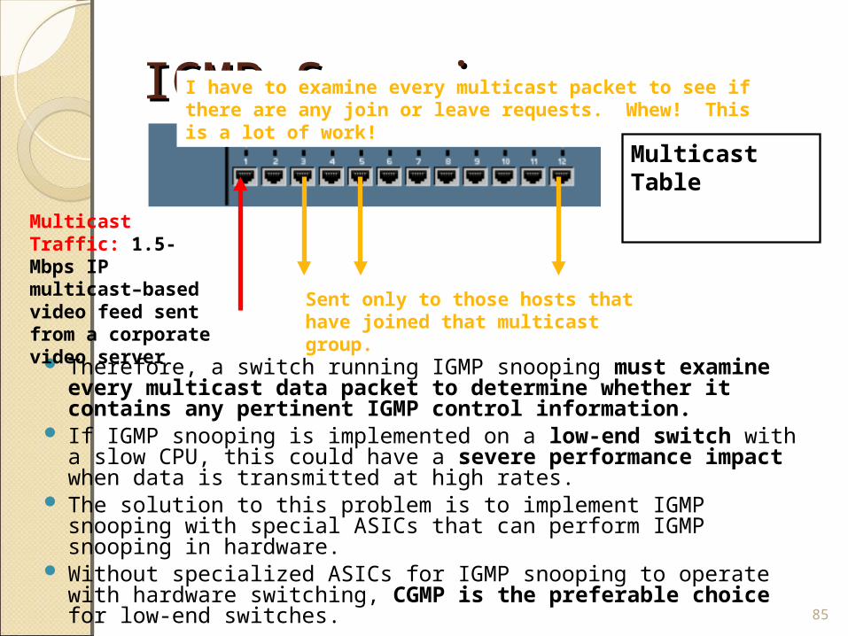
Multicast Traffic: 1.5-Mbps IP multicast–based video feed sent from a corporate video server
Sent only to those hosts that have joined that multicast group.
I have to examine every multicast packet to see if there are any join or leave requests. Whew! This is a lot of work!
Multicast Table
IGMP Snooping IGMP Snooping
Therefore, a switch running IGMP snooping must examine every multicast data packet to determine whether it contains any pertinent IGMP control information.
If IGMP snooping is implemented on a low-end switch with a slow CPU, this could have a severe performance impact when data is transmitted at high rates.
The solution to this problem is to implement IGMP snooping with special ASICs that can perform IGMP snooping in hardware.
Without specialized ASICs for IGMP snooping to operate with hardware switching, CGMP is the preferable choice for low-end switches. 85
Multicast Traffic: 1.5-Mbps IP multicast–based video feed sent from a corporate video server
Sent only to those hosts that have joined that multicast group.
I have to examine every multicast packet to see if there are any join or leave requests. Whew! This is a lot of work!
Multicast Table
CGMP CGMP
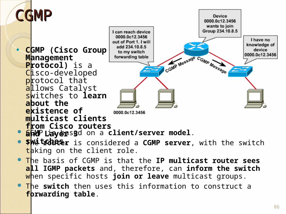
CGMP is based on a client/server model. The router is considered a CGMP server, with the switch taking
on the client role. The basis of CGMP is that the IP multicast router sees all
IGMP packets and, therefore, can inform the switch when specific hosts join or leave multicast groups.
The switch then uses this information to construct a forwarding table.
86
• CGMP (Cisco Group Management Protocol) is a Cisco-developed protocol that allows Catalyst switches to learn about the existence of multicast clients from Cisco routers and Layer 3 switches.
CGMPCGMP
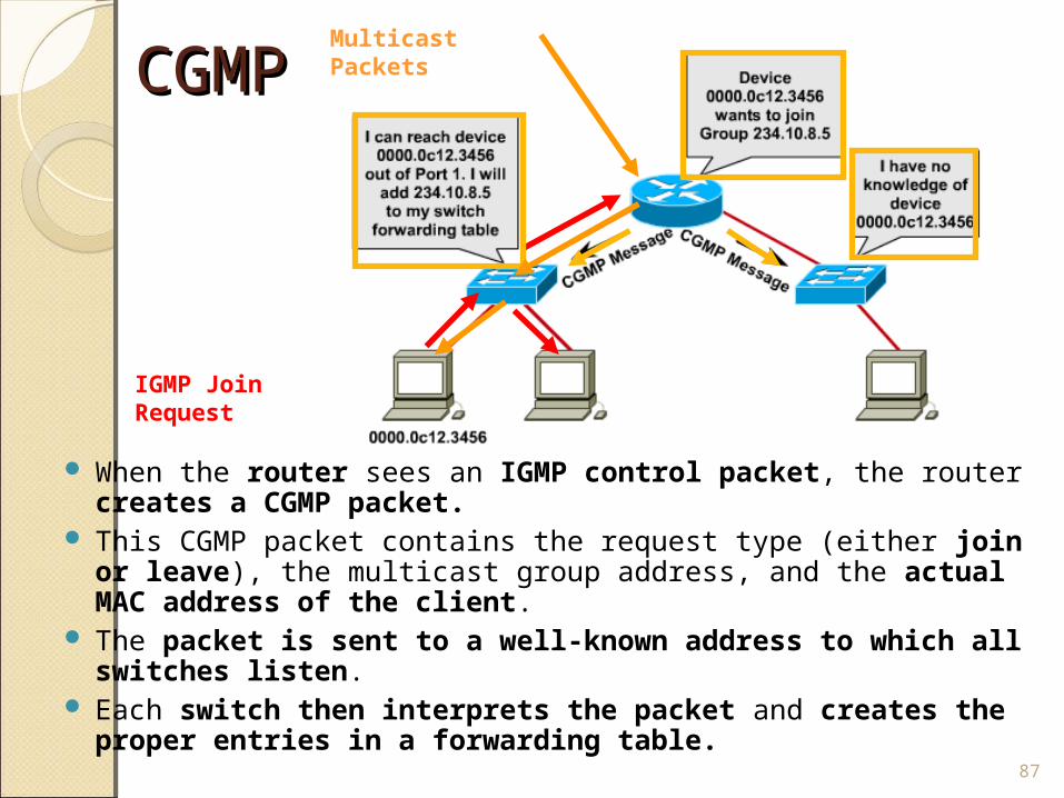
When the router sees an IGMP control packet, the router creates a CGMP packet.
This CGMP packet contains the request type (either join or leave), the multicast group address, and the actual MAC address of the client.
The packet is sent to a well-known address to which all switches listen.
Each switch then interprets the packet and creates the proper entries in a forwarding table.
87
IGMP Join Request
Multicast Packets
CGMPCGMP
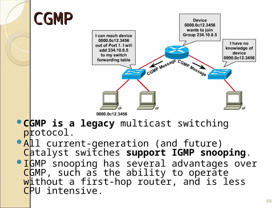
CGMP is a legacy multicast switching protocol.
All current-generation (and future) Catalyst switches support IGMP snooping.
IGMP snooping has several advantages over CGMP, such as the ability to operate without a first-hop router, and is less CPU intensive.
88
Configuring IGMPConfiguring IGMP
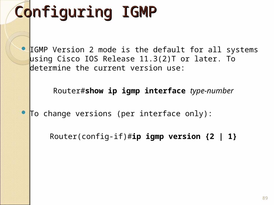
IGMP Version 2 mode is the default for all systems using Cisco IOS Release 11.3(2)T or later. To determine the current version use:
Router#show ip igmp interface type-number
To change versions (per interface only):
Router(config-if)#ip igmp version {2 | 1}
89
Configuring IGMP joinsConfiguring IGMP joins
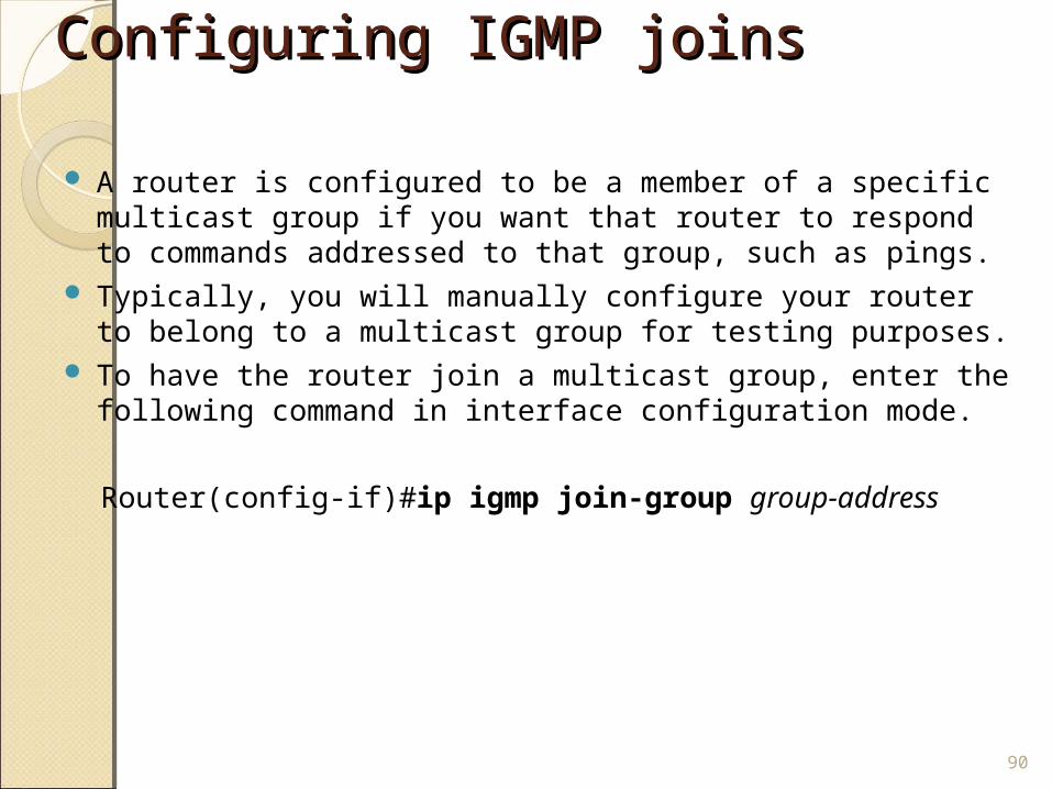
A router is configured to be a member of a specific multicast group if you want that router to respond to commands addressed to that group, such as pings.
Typically, you will manually configure your router to belong to a multicast group for testing purposes.
To have the router join a multicast group, enter the following command in interface configuration mode.
Router(config-if)#ip igmp join-group group-address
90
Configuring CGMPConfiguring CGMP
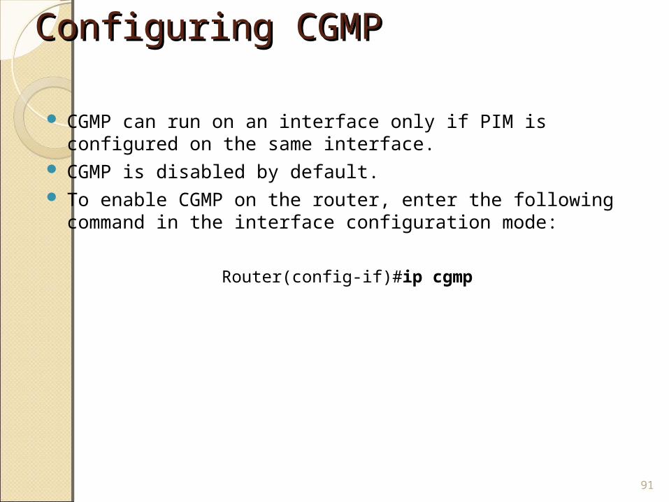
CGMP can run on an interface only if PIM is configured on the same interface.
CGMP is disabled by default. To enable CGMP on the router, enter the following command
in the interface configuration mode:
Router(config-if)#ip cgmp
91
Configuring CGMPConfiguring CGMP
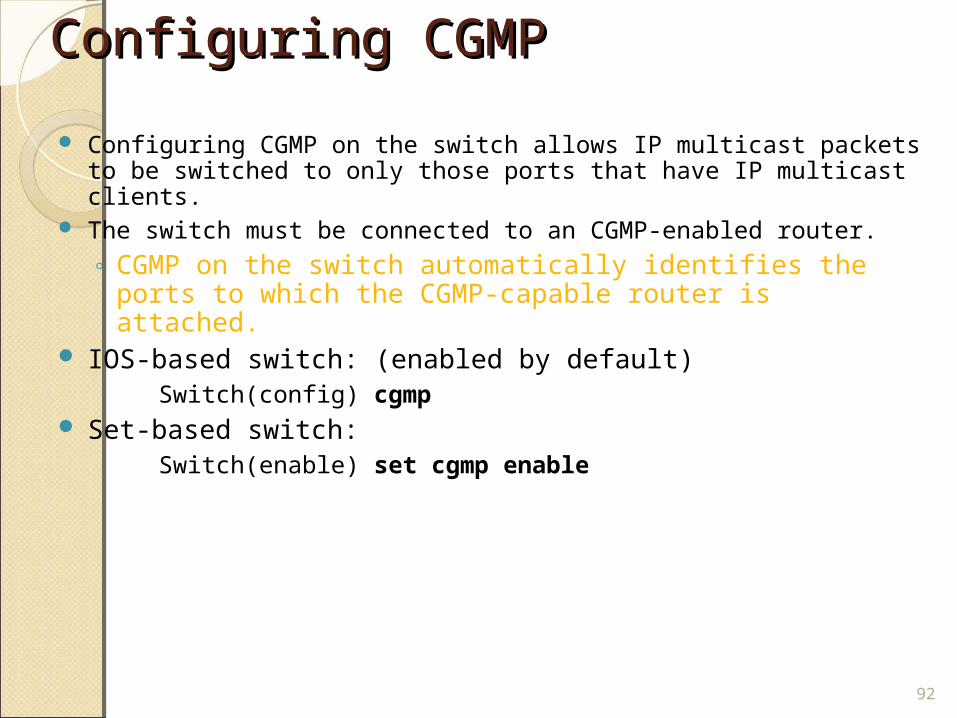
Configuring CGMP on the switch allows IP multicast packets to be switched to only those ports that have IP multicast clients.
The switch must be connected to an CGMP-enabled router.◦ CGMP on the switch automatically identifies the ports to
which the CGMP-capable router is attached. IOS-based switch: (enabled by default) Switch(config) cgmp Set-based switch: Switch(enable) set cgmp enable
92
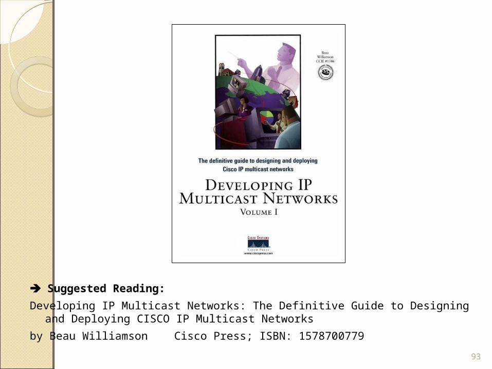
Suggested Reading:
Developing IP Multicast Networks: The Definitive Guide to Designing and Deploying CISCO IP Multicast Networks
by Beau Williamson Cisco Press; ISBN: 1578700779
93