Embed Size (px)
Citation preview
8/13/2019 Ip111 Munoz e
http://slidepdf.com/reader/full/ip111-munoz-e 1/16
1IP111-MUÑOZ-E
BEHAVIOR OF HYPERESTATIC BEAMS CORRODED AND REAPIRED WITH
MORTAR
A. Muñoz-Noval.Comision Estatal de Caminos, Queretaro, Mexico.
C. Andrade-Perdrix.Eduardo Torroja Construction Science Institute, Madrid, Spain.
D. Izquierdo-López.SANDO, Madrid, Spain.
ABSTRACT
One of the main causes of the concrete structures premature deterioration is the reinforcecorrosion. This process supposes the anodic regions metal dissolution, the reinforce crosssection loss will be the immediate effect of the corrosion. This work reaches a betterknowledge on the corrosion influence on hyperstatic reinforced concrete structuresdamaged by corrosion.
Seven hyperstatic reinforced concrete beams (3000 mm long, 15x20 mm cross section, 25mm cover) were made with 25 MPa concrete compressive strength, 3% of NaCl wereadded to the mix in order to induce corrosion in the bottom of mid span and top of middlesupport. A galvanostatic corrosion system was employed to accelerate the corrosionprocess. During all the tests, the beams were instrumented with strain gauges and loadcells to evaluate the strains and load bearing capacity by the beams during the tests. Afterthe steel cross sections loss (estimated with faradays law), the beams damaged zoneswere repaired with mortar only to carry out ultimate load test.
Study results demonstrated that the beams reparation was successful; despite just repairthe beams with mortar without steel addition, showing a repaired cross sections stiffnessincrease and bearing the same efforts that bore the control beam.
1. INTRODUCTION
Reinforce corrosion is one of the principal damage over the reinforced concrete structuresdesigned. This damage, reduce the safety and functionality of these structures.
Corrosion is a complex electrochemical phenomenon in its nature, evolution andcharacteristics which depend of many factors. Determining the initiation and corrosion rateof the process, the heterogeneity of attack morphology on the reinforce surface, are
additional complications for understanding the real state and the future behavior ofstructures damaged by reinforcement corrosion.
In this situation, many authors have focused their research on issues related to theinfluence of corrosion on the structural behavior in recent years.
There are three types of corrosion (Figure 1) that can occur in reinforced concretestructures:
8/13/2019 Ip111 Munoz e
http://slidepdf.com/reader/full/ip111-munoz-e 2/16
2IP111-MUÑOZ-E
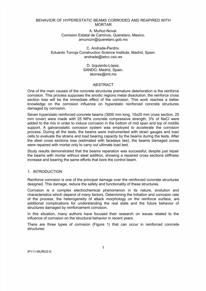
1.- Carbonation corrosion occurs when high enough concentrations of carbon dioxidereach and saturate the concrete cover and corrosion initiate in the area where thepH is reduced.
2.- Chloride corrosion is generated when high enough concentrations of chloride ionreach and saturate the concrete cover and begins the reinforce depassivation,causing pitting of the steel.
3.- Stress corrosion in reinforcement under stress.
Figure 1 - Different concrete structures corrosion types.
When the steel embedded in concrete corrode, dissolve the passive layer of steel andcorrosion products are formed whose volume occupied by the oxide (or hydroxide) isgreater than that occupied the original steel, creating pressure against the concrete coverof the steel, cracking and spalling of the cover. These cracks and / or detachment of theconcrete cover, besides being unsightly, can reduce the bond of steel and, potentially, thebehavior of structural elements.
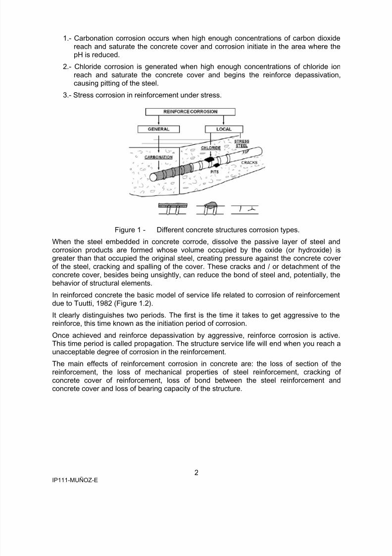
In reinforced concrete the basic model of service life related to corrosion of reinforcementdue to Tuutti, 1982 (Figure 1.2).
It clearly distinguishes two periods. The first is the time it takes to get aggressive to thereinforce, this time known as the initiation period of corrosion.
Once achieved and reinforce depassivation by aggressive, reinforce corrosion is active.This time period is called propagation. The structure service life will end when you reach aunacceptable degree of corrosion in the reinforcement.
The main effects of reinforcement corrosion in concrete are: the loss of section of thereinforcement, the loss of mechanical properties of steel reinforcement, cracking ofconcrete cover of reinforcement, loss of bond between the steel reinforcement and
concrete cover and loss of bearing capacity of the structure.
8/13/2019 Ip111 Munoz e
http://slidepdf.com/reader/full/ip111-munoz-e 3/16
3IP111-MUÑOZ-E
Figure 2 - Service life diagram, Tuutti, 1982.
The specific objective of this work is to obtain information about the nonlinear behavior ofstructures damaged by corrosion hyperstatic in their most vulnerable areas (the mid spanand the central support area) and repaired with mortar, by laboratory tests and finiteelement modeling.
2. STATE OF THE ART
The mass concrete has very good compressive strength but low tensile strength. If placingreinforcing bars, the resulting material (reinforced concrete) is able to resist the efforts ofthe buildings. Therefore, the structural concrete is based on combining the concretecompressive strength and steel tensile strength work.
The behavior of the repair mortar is very similar to normal concrete only increase theirtensile and compressive strengths and modulus of elasticity. Such materials are used for
patching repairs (REHABCON, REPCOR) whose objective is the restoration of physical,chemical and mechanical to acceptable conditions to the durability of the repair. In thosecases where the reinforcement corrosion is severe (loss of cross section) where due to anincreased load force a strengthening of the structure, the patch would not be enough andshould be strengthened with reinforced concrete structure.
When the stresses in the concrete exceed the value of the tensile strength then crackingoccurs. Due to its discrete nature, between two consecutive cracks of a reinforcedconcrete tension members, there is a concrete part that contributes to the resistance of thepart due to the bond stresses to steel. This collaboration between the cracks of concretepulled causes a tension stiffening effect.
The first publication found by McLeish, 1987, which summarized and highlight the different
effects of reinforcement corrosion in reinforced concrete elements, such as loss ofreinforcement area, loss of ductility of the reinforcement, cracking of concrete cover, lossof concrete cover on the compressed area of the element, tensile reinforcement coverdelamination, buckling of reinforcement subject to compression, reducing the bondbetween the concrete and steel, among others. The findings of this study were to corrosionand its consequences affect significantly the behavior of structures.
Okada et al. 1988, presents a study on the influence of longitudinal cracks due toreinforcement corrosion on reinforced concrete elements. Their conclusions were that theservice capacity and ultimate load of the repaired beams was higher than that of beams
8/13/2019 Ip111 Munoz e
http://slidepdf.com/reader/full/ip111-munoz-e 4/16
4IP111-MUÑOZ-E
without corrosion. The beams cracked have no significant reduction in carrying capacitywith respect to the beams without corrosion.
Cairns, 1993a, b, c, d performed experimental studies and presented a numerical modelfor concrete beams without reinforcement concrete cover. With these studies, highlightedthe factors that influence the behavior of concrete beams with unbonded reinforcement.
Cairns et al. concluded that the neutral axis depth decreases in the section of maximum
moment and, therefore, increases the maximum shortening of the concrete. On the otherhand, in sections outside the zone of maximum moment, the depth of the neutral axisincreases. They may become enlarged in the supposedly compressed beam, if the lengthof the exposed frame is wide enough.
Rodriguez et al. 1996 made a complex study on the influence of the corrosion behavior ofconcrete, making tests with reinforced beams and columns corroded and in service andultiamte load conditions. Studied different corrosion degrees, cross sections and theinteraction between corrosion and load.
The results of Rodriguez et al. allowed developing some models to assess the effects ofcorrosion of reinforcing steel in reinforced concrete. With these computational models canpredict a conservative value of the ultimate bending moment corroded (and ultimate shear)
by using conventional models of reinforced concrete, as specified in Eurocode 2, andconsidering the reduced sections of steel and concrete. These models have been used inthe calculation of structures that has damage caused by corrosion of reinforcing bars andwere able to calibrate (with real data and laboratory tests) to lead to the development ofguides or manuals, assessment, rehabilitation, repair and maintenance of existingstructures (CONTECVET, REHABCON, REPCOR, etc.)..
Mangat et al. 1999a, b studied the behavior of reinforced concrete beams with and withoutstirrups, damaged by corrosion of reinforcing steel (Mangat et al. 1999a) and beamsdamaged by corrosion and repaired (Mangat et al. 1999b).
From the results we can see that the rate of corrosion is also a parameter to study due tothe beams that have the same steel cross section loss due to corrosion present higher
reduction of ultimate moment capacity for beams for which a rate was applied 4 mA/cm2corrosion compared with the moment reduction of the beams to which they were given acorrosion rate of 1 mA/cm2.
In his second work, Mangat et al. 1999b studied the behavior of three materials used torepair damaged concrete beams due to corrosion of reinforcement (beams withoutstirrups). Analyzing the results and comparing the results obtained in other studies onrepaired beams is concluded that the behavior of the repaired structures depends on thematerial used in the repair.
Izquierdo et al 2002 studied the service performance of reinforced concrete structuresrepaired by patching. They made 11 reinforced concrete beams. The central part of thebeams was designed without stirrups to prevent corrosion-induced longitudinal
reinforcement could affect the stirrups and the concrete in the area. They were given anaccelerated corrosion system so that un10 lost ~ 15% section. The repair of the beamswas made with a commercial pre-mixed repair mortar
Izquierdo et al. modeled the beams with finite elements (2D and 3D) and nonlinearanalysis. The results of modeling of the beams are similar to those obtained in the testsand could predict the increased stiffness of the beams repaired with respect to the beamwithout damage, and ultimate load, location, inclination and opening cracks measured inthe tests. However, they had trouble getting the convergence of the model under a plasticregime.
8/13/2019 Ip111 Munoz e
http://slidepdf.com/reader/full/ip111-munoz-e 5/16
5IP111-MUÑOZ-E
Ballim et al. 2003 made tests on concrete beams damaged by corrosion of reinforcing stelin tension with two load levels. The study results show that the beams of series 2 showeddeterioration from corrosion 15% more than the beams of Series 1, possibly due toincreased cracking generated by the load level. On the third day of application of load andspeed up the process of corrosion found, as Rodriguez et al. 1996, with losses of around0.6% of the area of reinforcement corrosion, the deflection of the beams was 27% higher.
Similarly, Ballim et al. measure of crack width in beams during the test and found in someconcrete cover areas of the tension zone of the beams of series 2, the effect of spalling,contrary to Okada et al. 1988 and other authors, argue in their work, the longitudinalcracks have little effect in reducing the behavior of concrete elements corroded andcracked. The Ballim et al. argument is very reasonable, most measures of crackingperformed in previous works are performed when the applied load has been removed andthe crack widths are not generated and given that the actual maximum measured crackwidth are less, we can deduce that these crack widths do not affect the behavior ofcorroded elements.
3. EXPERIMENTAL
The variables on which the experiment was performed as follows:− The desired section loss of steel bars (10 and 20%)
− Areas of corrosion (lower bars of the central part of the span and top bars of theupper area of the central support)
− The behavior of the structure (with stirrups isolated and uninsulated)
The constants used in the trials were:
− The amount of current supplied to corrode the steel was constant for all specimens(200 μ A/cm2).
− The load imposed on the beams to measure their behavior and stiffness (100 kg.).
− The corrosion length (600 mm)
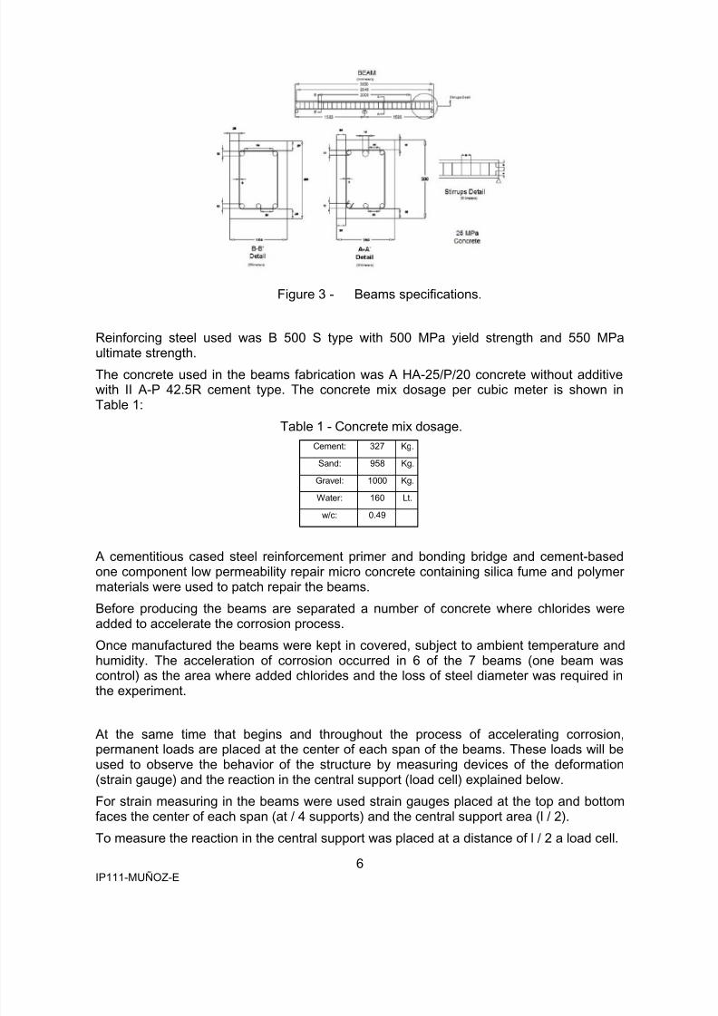
7 concrete beams specimens were fabricated with 3000 mm long, 150 x 200 mm crosssection, with a reinforced area of the mid span of two bars of 12 mm in diameter at the topand three on the bottom, and in the central support of two bars of 12 mm and 16 mm at thetop and three bars of 12 mm at the bottom with 25 mm cover (Figure 3.3). The stirrupswere 8 mm in diameter and were placed each 100 mm.
8/13/2019 Ip111 Munoz e
http://slidepdf.com/reader/full/ip111-munoz-e 6/16
6IP111-MUÑOZ-E
Figure 3 - Beams specifications.
Reinforcing steel used was B 500 S type with 500 MPa yield strength and 550 MPa
ultimate strength.The concrete used in the beams fabrication was A HA-25/P/20 concrete without additivewith II A-P 42.5R cement type. The concrete mix dosage per cubic meter is shown inTable 1:
Table 1 - Concrete mix dosage.
Cement: 327 Kg.
Sand: 958 Kg.
Gravel: 1000 Kg.
Water: 160 Lt.
w/c: 0.49
A cementitious cased steel reinforcement primer and bonding bridge and cement-basedone component low permeability repair micro concrete containing silica fume and polymermaterials were used to patch repair the beams.
Before producing the beams are separated a number of concrete where chlorides wereadded to accelerate the corrosion process.
Once manufactured the beams were kept in covered, subject to ambient temperature andhumidity. The acceleration of corrosion occurred in 6 of the 7 beams (one beam wascontrol) as the area where added chlorides and the loss of steel diameter was required inthe experiment.
At the same time that begins and throughout the process of accelerating corrosion,permanent loads are placed at the center of each span of the beams. These loads will beused to observe the behavior of the structure by measuring devices of the deformation(strain gauge) and the reaction in the central support (load cell) explained below.
For strain measuring in the beams were used strain gauges placed at the top and bottomfaces the center of each span (at / 4 supports) and the central support area (l / 2).
To measure the reaction in the central support was placed at a distance of l / 2 a load cell.
8/13/2019 Ip111 Munoz e
http://slidepdf.com/reader/full/ip111-munoz-e 7/16
7IP111-MUÑOZ-E
The device used to apply the corrosion current, strain gauges used to measure thedeformation and load cells used to measure the reaction is connected to a data acquisitionunit to take measurements every hour throughout the test accelerated corrosion (andsubsequently load testing of the beams every 6 seconds throughout the test) of device,gauges and load cells.
Throughout the accelerated corrosion and ultimate load test was performed cracks widthsin all elements.
Once the corrosion process finish, retired on cracked concrete cover using a chisel andhammer to avoid damaging the area of concrete and reinforcing steel, cleaning thecorrosion product of reinforcing steel and take measurements of the residual diameterssteel bars.
After performing the measurements of the residual diameters of reinforcing bars andlongitudinal with a digital caliper, we proceeded to clean the surface of concrete and applya coating layer 610 Sika MonoTop to allow better bond between the concrete substrateand repair mortar. While still fresh in the applied coating proceeded to empty the repairmortar mix Sika MonoTop 612 to complete the repair process.
Once past 28 days and setting repair mortar was conducted to ultimate load test. The load
test was the same for all specimens and was performed in a universal machine with twoloaded pistons with a capacity of 20 tons (200 kN) each and the rate of load applicationwas 1000 kg / min.
To measure the applied load, load cells placed between the pistons and metal profiles thatI helped to spread the load. Among the profiles and support beams were placed at 1 / 6the length of the beam. In the center of each span were placed deflection digital meters. Atthe center of the beam was placed a load cell to measure the reaction in the "support"central and placed strain gauges to measure the deformation is placed in the same way asdiscussed in the accelerated corrosion test.
4. RESULTS AND DISCUSSION
4.1 Accelerated corrosion process
In the present study, an analysis of the beams tested is made in the development of whichhave been taken into account the equilibrium equations and compatibility, taking intoaccounts the behavior of materials defined by their constitutive equations.
In the general approach of the work we have considered the following hypotheses:
• It assumes the beam embedded in the central support to reach the yielding of the area.Usually occurs earlier in the support than in the span, due to the highest moment in thisapplied in this section, except in cases where corrosion attacks take place in the midspan.
• It is recognized that there is reinforce in the sections analyzed, with enough anchoragelength and covering the displacements of bending the law.
• When you reach the plasticization on the central support, it supports the formation of akneecap, and can cause depletion of the beam by the lack of rotation capacity in thecentral support or depletion in the section of the span. These effects may occur sooneror later, if the depletion zone has a section loss due to corrosion and is repaired.
8/13/2019 Ip111 Munoz e
http://slidepdf.com/reader/full/ip111-munoz-e 8/16
8IP111-MUÑOZ-E
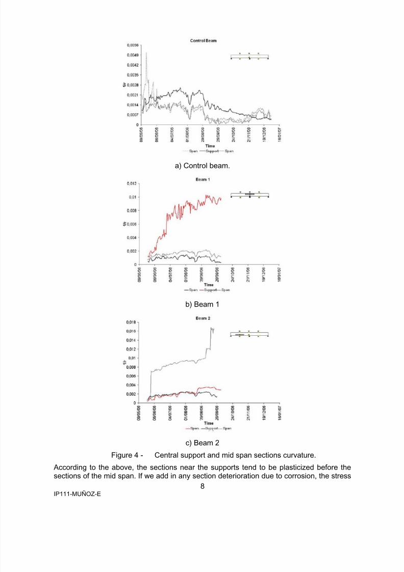
a) Control beam.
b) Beam 1
c) Beam 2
Figure 4 - Central support and mid span sections curvature.
According to the above, the sections near the supports tend to be plasticized before thesections of the mid span. If we add in any section deterioration due to corrosion, the stress
8/13/2019 Ip111 Munoz e
http://slidepdf.com/reader/full/ip111-munoz-e 9/16
9IP111-MUÑOZ-E
redistribution along the beam and corroded sections plasticize will occur earlier. If corrodecentral support section, this section plasticize before and begins to support the mid spanefforts of the support section cannot bear to plasticizing and the beam is broken.Otherwise, when corrosion occurs on the section of mid span, the support section and thesection of plasticized mid span cannot bear all the efforts that the support section and failsto support the beam breaks. The placement of strain gauges and permanent loads foraccelerated corrosion tests provide direct information to confirm this and, in turn, this is
confirmed by the diagrams moment - curvature obtained with the test data. Reactionsmeasured in the beams 2, 4 and 6 load cells tended to increase as the trial proceeded,while the reactions of the beams 1, 3 and 5 were stabilized after a while, remainingunchanged. The reactions of beams 1, 3 and 5 are slightly lower than that of the controlbeam, while the reactions of the beams 2, 4 and 6 are slightly higher. This confirms thehypothesis of redistribution efforts, as seen in the measurements of the gauges.
Upon completion of the accelerated corrosion test measured the cracks along the entirebeam and the cracks generated by corrosion of reinforcement in the defined area. Thelongitudinal cracks generated in the beams 1 to 4 due to the acceleration of corrosionthickness were expected while the widths of longitudinal cracks in beams 5 and 6 werelower than expected. The lengths of the cracks are almost equal to the corrosion of thebeams 1 to 4 lost 10% of the reinforce section, while the lengths of cracks in beams 5 and6 are up to a meter due to 20 % loss of section. Because of this, the crack widthsgenerated in the beams with a 20% section loss was minor.
4.2 Ultimate test load.
During the ultimate load test was observed that the gauge G3, placed in the supportsection, and gauges G2 and G6, placed in the bottom of each span of the beams is thatmeasured greater deformation depending on the corrosion-damaged area because theywere placed in the tensile zone. G4 and G5 gauges measured in some cases thedeformation of the compressed area of the support section and mid span in some beamsrespectively.
In terms of deflections, it was observed that generated in the mid spans of beams Control,
1, 3 and 5 are very similar because the corrosion damage was generated in the centralsupport area, while the deflections beams 2, 4 and 6 are different because the generationof corrosion damage in one of the mid span and deflection was greater.
Reactions measured by load cells placed on the beams were kept constant and there weresome pending changes that indicate the plasticizing of the sections and the behavior of thebeams. In the case of the Control beam the reaction remains linear while for beams 1, 3and 5 the slope of the line has a slight increase once the yielding of the section damagedby corrosion and beams 2, 4 and 6, the slope of the line has a slight decrease once theplasticizing of the area damaged by corrosion.
Once you completed the process of accelerated corrosion and taken measures lossessection of the reinforcement, it was observed that the efficiency of corrosion was
approximately 77%. This may be because the test lasted more than three months to thebeams and it is possible that the device employee was unable to keep current lossesestimated. Another important factor to consider in the tests was that these took placeduring the summer where the temperatures were very high and low humidity, so it is notkept moist at all times and lost contact, the applied current decreased considerably.
Losses section of reinforcement beams 1 to 4 (10% loss of section approx.) were uniformin bars, while losses on some stirrups of beams 1 and 2 were localized. The beams 5 and6 losses (20% loss of section approx.) were more localized, coming to have losses of up to60% section. However, in general, the results of corrosion section loss were lower than
8/13/2019 Ip111 Munoz e
http://slidepdf.com/reader/full/ip111-munoz-e 10/16
10IP111-MUÑOZ-E
estimated and gravimetric losses were higher than those estimated there were at most ofthe stirrups and some points of the main bars.
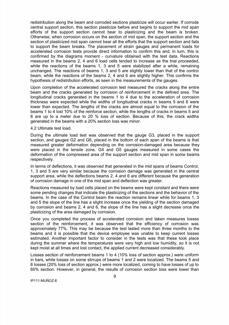
a) Control beam
b) Beam 1
c) Beam 2
Figure 5 - Ultimate load test theoretical and experimental reaction comparison.
8/13/2019 Ip111 Munoz e
http://slidepdf.com/reader/full/ip111-munoz-e 11/16
11IP111-MUÑOZ-E
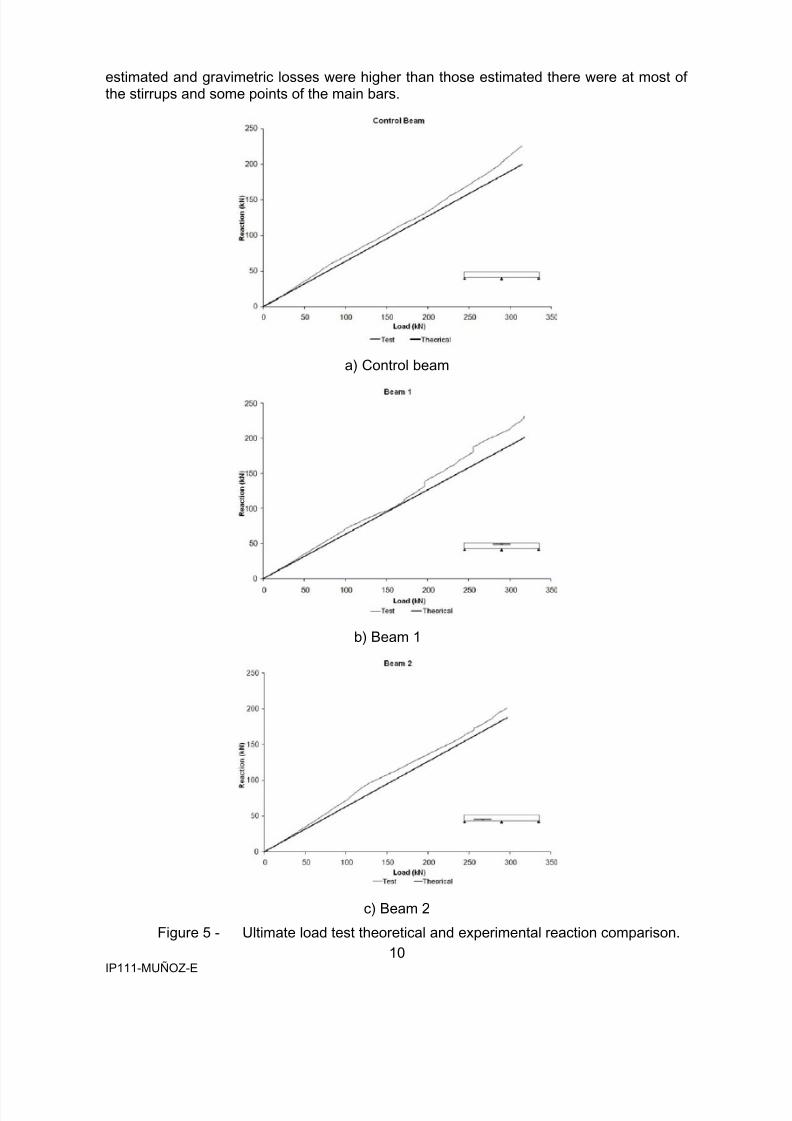
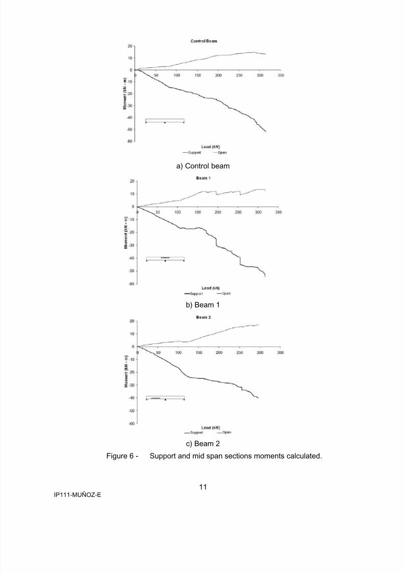
a) Control beam
b) Beam 1
c) Beam 2
Figure 6 - Support and mid span sections moments calculated.
8/13/2019 Ip111 Munoz e
http://slidepdf.com/reader/full/ip111-munoz-e 12/16
8/13/2019 Ip111 Munoz e
http://slidepdf.com/reader/full/ip111-munoz-e 13/16
13IP111-MUÑOZ-E
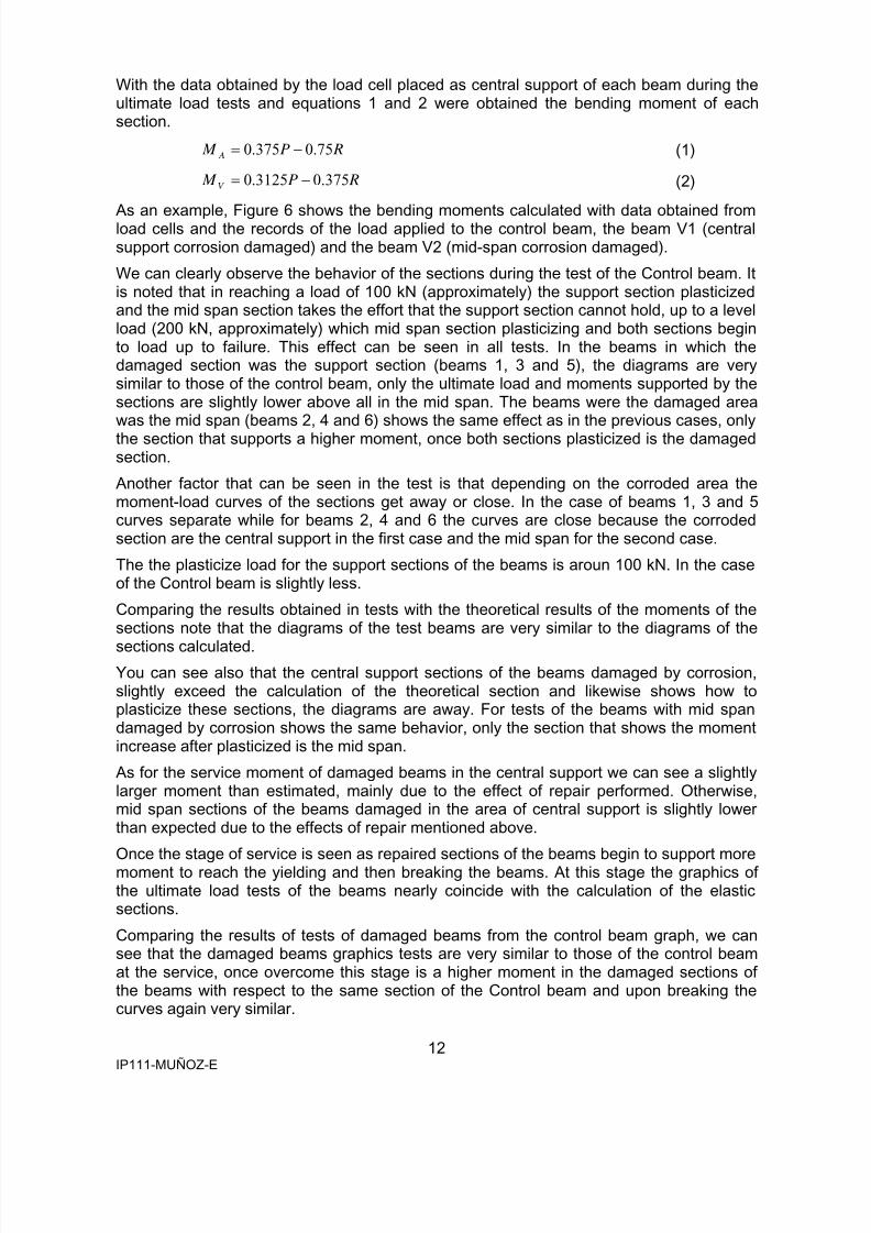
a) Control beam
b) Beam 1
c) Beam 2
Figure 7 - Theoretical and experimental moments comparison of ultimate loadtest.
8/13/2019 Ip111 Munoz e
http://slidepdf.com/reader/full/ip111-munoz-e 14/16
14IP111-MUÑOZ-E
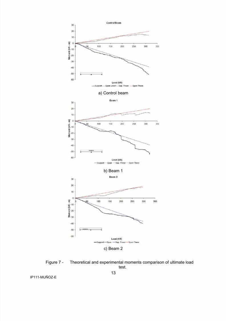
a) Beam 1 vs. Control beam
b) Beam 2 vs. Control beam
Figure 8 - Control beam and corroded beams moments resulting from ultimateload test comparison.
The purpose of structure repair is to restore its original properties. For this work the patchrepairs of the beams was chosen and observe their behavior, especially the effortsredistribution along the beams during the ultimate load tests.
The patch repair of the beams change their behavior to ductile due to the reinforced crosssection loss was not enough to change the beams behavior and increase their fragility.This confirms what has been said about the behavior of the damaged sections of thebeams compared with the control beam.
In the figure above you can see the sections stiffness change of the beams, especially thesections that were repaired. This confirms that the repair mortar was adequate and, ingeneral, be able to restore the stiffness lost due to corrosion damage to that of the samesection without damaging of the control beam. In some cases sections repaired restoreand increase the stiffness with respect to the control beam.
8/13/2019 Ip111 Munoz e
http://slidepdf.com/reader/full/ip111-munoz-e 15/16
15IP111-MUÑOZ-E
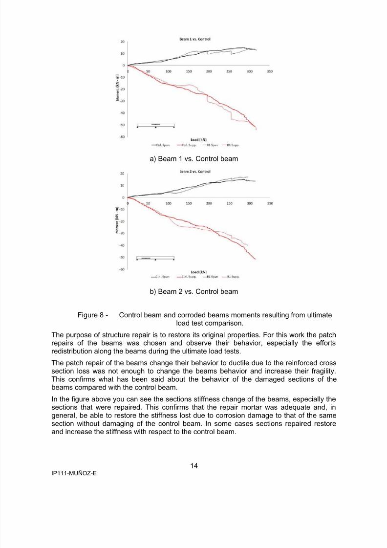
Figure 9 shows schematically the effect achieved by the patch repair made to the beamstaking into account that only repaired the concrete cover and did not recover the reinforcedcross section loss due to corrosion to strengthen the beams.
Figure 9 - Repair effect over the beams.
5. CONCLUSSIONS
The most relevant conclusions drawn from the results of tests of the beams are:
1.- There are not found in the literature a study about hyperstatic structures and lessdamaged by corrosion. This work is the first to study the behavior of hyperstaticreinforce concrete elements damaged by reinforce corrosion, with loads appliedduring the corrosion process, repaired and loaded until failure.
2.- In most cases, the data obtained in accelerated corrosion tests and ultimate load
tests have confirmed the efforts redistribution hypothesis startup raised in thispaper.
3.- Although that the static load applied during the corrosion process of the sections ofthe beams was small it has been possible to detect changes in the curvature ofdifferent sections of the beams and measuring the reactions of the load cells placedas support in the central part of the beams.
4.- The beams behavior during loading tests was very similar to that estimated with theequations of elastic sections.
5.- With respect to the control beam most of the beams damaged by corrosion andrepaired showed an increase in stiffness in the service stage and the ultimate loadtension stiffening effect with respect to the control beam due to patch repair ofdamaged sections by corrosion with mortar due to higher properties of repairmaterial than those of the original concrete beams.
REFERENCES
1. Tuutti, K. 1982. Corrosion of steel in concrete.2. REHABCON, 2004. EC DG ENTR-C-2, Innovation and SME Program, IPS-2000-0063.3. REPCOR. I+D en Estrategias para la Reparación de Estructuras de Hormigón,
Proyecto PROFIT FIT – 380000-2004-21.
8/13/2019 Ip111 Munoz e
http://slidepdf.com/reader/full/ip111-munoz-e 16/16
16IP111-MUÑOZ-E
4. McLeish, A. 1987. Structural assessment. manual for lyfe cycle aspects of concrete inbuildings and structures. Taywood Engineering Limited: B4.1-B4.22.
5. Okada, K., Kobayashi, K., & Miyagawa, T. 1988. Influence of longitudinal cracking dueto reinforcement corrosion on characteristics of reinforced concrete members. ACIStructural Journal, 85(2): 134-140.
6. Cairns, J. 1993. Changes in reinforced concrete beams behavior induced byreinforcement corrosion. Proceedings of 4th International Conference on Structural
Failure, Durability and Retrofitting: 447-454.7. Cairns, J. 1993. Consequences of bond loss for behavior of reinforced concretebeams. Proceedings of 5th International Conference on Structural Faults and Repairs,3: 149-154.
8. Cairns, J., & Watson, D. 1993. Structural behavior of concrete repairs: Behavior ofbeams with exposed aggregates. Proceedings of 5th International Conference onDeterioration and Repairs of Reinforced Concrete in the Arabian Gulf.
9. Cairns, J., & Zhao, Z. 1993. Structural behavior of concrete beams with exposedreinforcement. Proceedings of the Institution of Civil Engineers, Structures andBuildings, 99(2): 141-154.
10. Rodriguez, J., Ortega, L. M., & Casal, J. July 1996. Load bearing capacity of concretecolumns with corroded reinforcement. Proc., 4th Int. Symp. on Corrosion of
Reinforcement in Concrete Construction.11. Rodríguez, J., Ortega, L. M., Casal, J., & Diez, J. M. 1996. Comportamiento
estructural de vigas de hormigón con armaduras corroídas. Hormigón y Acero, 837 - 8- 23: 113-131.
12. Rodríguez, J., Ortega, L. M., Casal, J., & Díez, J. M. June 1996. Corrosion ofreinforcement and service life of concrete structures. 7th Int. Conference on Durabilityof Building Materials and Components, 7(1): 117-126.
13. Eurocode 2: Design of concrete structures - part 1: General rules and rules forbuildings. Brussels: prEN 1992-1-1. CEN. European Committee for Standardization.April 2003.
14. CONTECVET. Manual EC Innovation Program IN30902I15. Mangat, P. S., & Elgarf, M. S. 1999. Flexural strength of concrete beams with
corroding reinforcement. ACI Structural Journal, 96(1).16. Mangat, P. S., & Elgarf, M. S. April 1999. Strength and serviceability of repaired
reinforced concrete beams undergoing reinforcement corrosion. Magazine of ConcreteResearch, 51(2): 97-112.
17. Izquierdo et al 2002Izquierdo, D., Río, O., Andrade, C., & Alonso, C. Noviembre, 2002.Comportamiento en servicio de estructuras de hormigón armado reparadas porparcheo superficial: Modelización numérica. Comunicaciones II Congreso de laAsociación Científico-Técnica del Hormigón Estructural, 2: 755.
18. Ballim, Y., & Reid, J. C. 2003. Reinforcement corrosion and the deflection of RCbeams––an experimental critique of current test methods. Cement and ConcreteComposites, 25(6): 625-632.
19. Asociación Española de Normalización. 1994. Barras corrugadas de acero soldablepara armaduras de hormigón armado. Madrid, España: AENOR.