Embed Size (px)
Citation preview

Explosion-protectedThree-Phase Low-Voltage Squirrel-Cage
Motors, flameproof enclosurefrom 0.12 to 630 kW
M1.23e · 2001
ELECTRICAL MACHINES, DRIVE SYSTEMS AND SYSTEM ENGINEERING
IP55
Frame size 63-45055II 2 G EExd(e) IIC(B) T455

Three-phase low-voltagesquirrel-cage motors, IP55II 2 G EExd(e) IIC(B) T4Flameproof enclosure “d“Shaft centre heights 63-450
� Single speed motors� Change pole motors� Motors for frequency converter supply
Technical Catalouge M1.23 e ✦ 2001Supersedes: � Technische Liste M1.23 e ✦ 2000
RevisionsAll technical data, outputs, dimensions and weights, stated in this catalogue, are subject to change without notice. Illustrations do not purport to show constructional details.08.01
U2_g.fm Seite 1 Montag, 17. September 2001 9:51 09
Gen
eral
info
rmat
ion
1
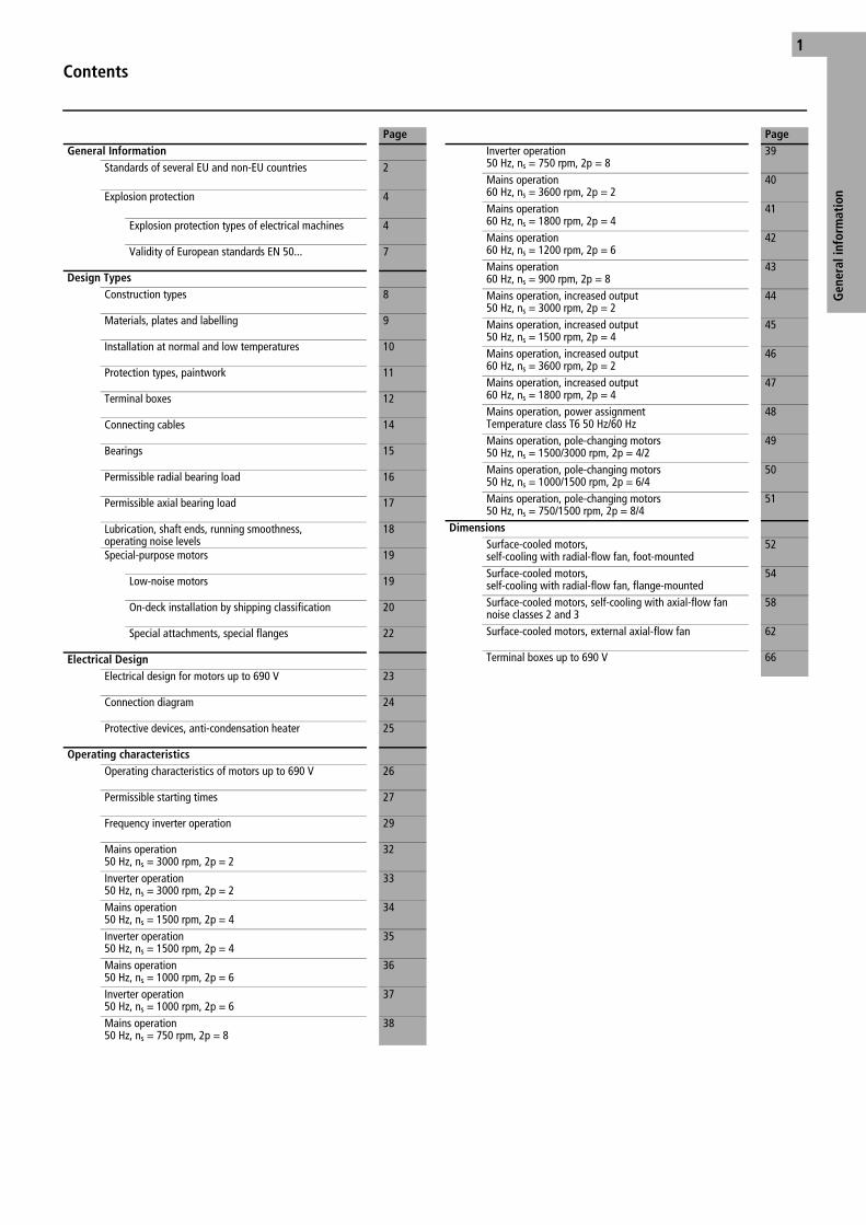
Contents
PageGeneral Information
Standards of several EU and non-EU countries 2
Explosion protection 4
Explosion protection types of electrical machines 4
Validity of European standards EN 50... 7
Design TypesConstruction types 8
Materials, plates and labelling 9
Installation at normal and low temperatures 10
Protection types, paintwork 11
Terminal boxes 12
Connecting cables 14
Bearings 15
Permissible radial bearing load 16
Permissible axial bearing load 17
Lubrication, shaft ends, running smoothness, operating noise levels
18
Special-purpose motors 19
Low-noise motors 19
On-deck installation by shipping classification 20
Special attachments, special flanges 22
Electrical DesignElectrical design for motors up to 690 V 23
Connection diagram 24
Protective devices, anti-condensation heater 25
Operating characteristicsOperating characteristics of motors up to 690 V 26
Permissible starting times 27
Frequency inverter operation 29
Mains operation50 Hz, ns = 3000 rpm, 2p = 2
32
Inverter operation50 Hz, ns = 3000 rpm, 2p = 2
33
Mains operation50 Hz, ns = 1500 rpm, 2p = 4
34
Inverter operation50 Hz, ns = 1500 rpm, 2p = 4
35
Mains operation50 Hz, ns = 1000 rpm, 2p = 6
36
Inverter operation50 Hz, ns = 1000 rpm, 2p = 6
37
Mains operation50 Hz, ns = 750 rpm, 2p = 8
38
Inverter operation50 Hz, ns = 750 rpm, 2p = 8
39
Mains operation60 Hz, ns = 3600 rpm, 2p = 2
40
Mains operation60 Hz, ns = 1800 rpm, 2p = 4
41
Mains operation60 Hz, ns = 1200 rpm, 2p = 6
42
Mains operation60 Hz, ns = 900 rpm, 2p = 8
43
Mains operation, increased output50 Hz, ns = 3000 rpm, 2p = 2
44
Mains operation, increased output50 Hz, ns = 1500 rpm, 2p = 4
45
Mains operation, increased output60 Hz, ns = 3600 rpm, 2p = 2
46
Mains operation, increased output60 Hz, ns = 1800 rpm, 2p = 4
47
Mains operation, power assignmentTemperature class T6 50 Hz/60 Hz
48
Mains operation, pole-changing motors50 Hz, ns = 1500/3000 rpm, 2p = 4/2
49
Mains operation, pole-changing motors50 Hz, ns = 1000/1500 rpm, 2p = 6/4
50
Mains operation, pole-changing motors50 Hz, ns = 750/1500 rpm, 2p = 8/4
51
DimensionsSurface-cooled motors, self-cooling with radial-flow fan, foot-mounted
52
Surface-cooled motors, self-cooling with radial-flow fan, flange-mounted
54
Surface-cooled motors, self-cooling with axial-flow fannoise classes 2 and 3
58
Surface-cooled motors, external axial-flow fan 62
Terminal boxes up to 690 V 66
Page
INHALT_G.FM Seite 1 Montag, 17. September 2001 9:41 09

Standards Of Several EU and Non-EU Countries
Gen
eral
Info
rmat
ion
2
Country International Europe Germany Great Britain
Title IEC – International Electrotechnical Commission
EN – CENELEC European Committee for Electrotechnical Standardisation
DIN/VDE – German Industrial Standard/Association of German Electrotechni-cians
BS – British Standards
Electrical rotating machines Rated operation and technical data
IEC 60 034-1,IEC 60 085
EN 60 034-1 DIN EN 60 034-1/VDE 0530 Part 1
BS 4999: P1 BS 4999: P69
Protection types of rotating electrical machines IEC 60 034-5 EN 60 034-5 DIN IEC 34 Part 5/VDE 0530 Part 5
BS 4999: P20
Cooling methods of rotating electrical machines IEC 60 034-6 EN 60 034-6 DIN EN 60 034-6/VDE 0530 Part 6
BS 4999: P21
Construction types of rotating electrical machines IEC 60 034-7 EN 60 034-7 DIN EN 60 034-7/VDE 0530 Part 7
BS 4999: P22
Terminal markings and direction of rotation for electrical machines
IEC 60 034-8 – DIN/VDE 0530 Part 8 BS 4999: P3
Noise emission, limit values IEC 60 034-9 EN 60 034-9 DIN EN 60 034-9/VDE 0530 Part 9
BS 4999: P51
Startup behaviour of squirrel-cage motors at 50 Hz up to 690 V
IEC 60 034-12 EN 60 034-12 DIN EN 60 034-12VDE 0530 Part 12
–
Vibration severity of rotating electrical machines IEC 60 034-14 EN 60 034-14 DIN EN 60 034-14VDE 0530 Part 14
BS4999: P50
Mounting dimensions and ratings assignment for IM B3
IEC 60 0721) – DIN 42 673 Sh. 32) BS 4999: P101)
Mounting dimensions and ratings assignment for IM B5, IM B10 and IM B14
IEC 60 0721) – DIN 42 677 Sh. 32) BS 4999: P101)
Cylindrical shaft ends for electric machines IEC 60 0721) – DIN 748 Part 3 BS 4999: P101)
Electrical apparatus for explosive atmospheres,general provisions
IEC 60 079-0 EN 50 014 DIN EN 50 014/VDE 0170/0171 Part 1
BS EN 50 014
Electrical apparatus for explosive atmospheres,flameproof enclosure “d”
IEC 60 079-1 EN 50 018 DIN EN 50 018/VDE 0170/0171 Part 5
BS EN 50 018
Electrical apparatus for explosive atmospheres, increased safety “e”
IEC 60 079-7 EN 50 019 DIN EN 50 019/VDE 0171 Part 6
BS EN 50 019
Designation of explosion-proof electrical equipment IIA – IIC Part 1 – Part 4
II 2 G EEx d(e) IIA – IIC T1 – T6
m
m
Certificate, including symbol of inspection authority – – PTB ...ATEX...3)
BVS ...ATEX...AS No. Ex...3)
Symbol of inspection authority – – PTB BVS
BASEEFA
Notes Due to compliance with the IEC publications mentioned above, special adaptation to foreign regulations is not required in many cases.
1) Applies only to dimensions and frame sizes2) Applies only to single-speed motors of frame sizes 90L to 315M for temperature class T4 3) EU-approved inspection authorities, whose certification is valid and recognized in all EU countries.
Ff01a01g.fm Seite 2 Montag, 17. September 2001 9:41 09
3
Gen
eral
Info
rmat
ion
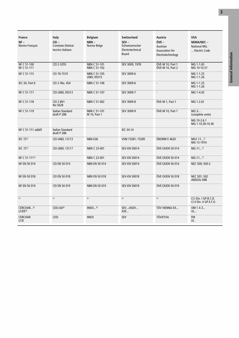
France Italy Belgium Switzerland Austria USA
NF – Norme Français
CEI – Comitato Elettrattecnico Italiano
NBN – Norme Belge
SEV –Schweizerischer Electrotechnical Board
ÖVE –Austrian Association forElectrotechnology
NEMA/NEC – National MG.- ... Electric Code
NF C 51-100 NF C 51-111
CEI 2-3355 NBN C 51-101 NBN C 51-102
SEV 3009, 1978 ÖVE-M 10, Part 1ÖVE-M 10, Part 2
MG 1-1.65 MG 10-10.37
NF C 51-115 CEI 70-1519 NBN C 51-105UNEL 05515
SEV 3009-6 MG 1-1.25 MG 1-1.26
IEC-34, Part 6 CEI 2-/No. 454 NBN C 51-106 SEV 3009-6 - MG 1-1.25 MG 1-1.26
NF C 51-117 CEI-UNEL 05513 NBN C 51-107 SEV 3009-7 - MG 1-4.03
NF C 51-118 CEI 2-8V1No 5628
NBN C 51-002 SEV 3009-8 ÖVE-M 1, Part 1 MG 1-2.61
NF C 51-119 Italian Standard draft P 288
NBN C 51-101M 10, Part 1
SEV 3009-9 ÖVE-M 10, Part 1 MG 3-... (complete units)
MG 10-2.6.1MG 1-10.30-10.36
NF C 51-111 addd1 Italian Standard draft P 288
IEC 34-14
IEC 721) CEI-UNEL 13113 NBN 636 VSM 15281; 15285 ÖNORM E 4620 MG1-11...1) MG 13-1974
IEC 721) CEI-UNEL 13117 NBN C 23-001 SEV-EN 50014 ÖVE EX/EN 50 014 MG-11...1)
NF C 51-1111) NBN C 23-001 SEV-EN 50014 ÖVE EX/EN 50 014 MG-11...1)
NF EN 50 014 CEI EN 50 014 NBN EN 50 014 SEV-EN 50014 ÖVE EX/EN 50 014 NEC 500; 500-2
NF EN 50 018 CEI EN 50 018 NBN EN 50 018 SEV-EN 50018 ÖVE EX/EN 50 018 NEC 501; 502 ANSI/UL-698
NF EN 50 019 CEI EN 50 019 NBN EN 50 019 SEV-EN 50019 ÖVE EX/EN 50 019
m
m
m
m
m CI.I Div. I GP.B.C.D. CI.II Div. II GP.E.F.G
CERCHAR...3) LCIEE3)
CESI-AD3) INIEX...3) SEV.../ASEV...ASE...
TÜV VIENNA EX... OM 1 A 3... UL...
CERCHAR LCIE
CESI INIEX SEV TÜV/ETVA FM UL
Ff01a01g.fm Seite 3 Montag, 17. September 2001 9:41 09

Explosion ProtectionExplosion Protection Types of Electrical Machines to DIN EN 50 014, VDE 0170/0171 Part 1
Gen
eral
Info
rmat
ion
4
Protection typeletter symbol
Constructional requirements Protection concept Application for type of electrical machine
Flameproof enclosure “d” DIN EN 50 018 VDE 0170/0171 Part 5
Apparatus for zones 1 and 21)
All potential ignition sources are housed inside a flameproof enclosure. Unavoid-able sealing surfaces are therefore designed as flameproof joints, so that, in case of ignition of an explosive atmosphere inside the enclosure, the explosive atmosphere is not transferred to the potentially explosive atmosphere surrounding the enclosure.
All types of motors, e.g. • squirrel-cage motors• slipring motors• commutator motors For all modes of operation (S1 to S9) for severe starting conditions and variable-speed drive units, e.g. by means of frequency inverters.
Increased safety “e” DIN EN 50 014, VDE 0170/0171 Part 6
Apparatus for zones 1 and 21)
Here, steps must be taken to ensure that the creation of sparks, electric arcs and inadmissible heating processes is pre-vented during proper operation of the apparatus.
Only squirrel-cage motors with adapted motor protection switch.
tE-time is a requirement.
Non-sparking “n” IEC 60 079-15DIN EN 50 021, VDE 0170/0171 Part 16
Electrical apparatus for explosive atmospheres. Protection type “n”
Apparatus for zone 21) (zone 2 – apparatus)
Under normal operating conditions, no sparks, electric arcs or inadmissible tem-peratures occur.
If sparks, electric arcs or inadmissible temperatures occur during normal operation, the enclosures, including the terminal box, must either be constructed to protection type IP54 (i.e. at an excess pressure of 4 mbar they must take more than 30 seconds to drop to 2 mbar [restricted breathing]) or both housing and terminal box must be pressurized by simple means.
Squirrel-cage motors of protection type IP20 for enclosed areas. For installation outdoors, protection type IP44 or IPW24 motor protection switch.All types of motors, e.g. • slipring motors• commutator motors with motor protection switches and overpressure monitoring.
Prevention of discharge of sparks created under normal operating condi-tions. Manufacturers’ information about these measures.
Notes 1) DIN EN 60 079-14, VDE 165 Part 1, Electrical Equipment for Hazardous Areas (except for mines)
The motors have been tested and certified in ac-cordance with the new European Directive 94/9/EC (ATEX 100a) by the German Federal Institute of Physics and Metrology (PTB). They therefore already comply with the latest European regula-tions that will continue to be valid after the year 2003. The Directive regulates the type of devices and protective systems suitable for use in haz-ardous areas and will be applicable from the 30.06.2003 throughout Europe for the market-ing of apparatus.
The three-phase motors are housed in a flame-proof enclosure to DIN EN 50 014 VDE 0170/0171 for all explosion protection groups and temperature classes.
The standard version of shaft centre heights 63-400 complies with the requirements of the highest explosion protection group (IIC) and temperature class (T4), which also cover all low-er groups and temperature classes. Motors with shaft centre height 450 comply with the
requirements of explosion protection group IIB and temperature class T4.
The issued test certification does not contain electrical data for the tested motor. It merely confirms that the motor is inherently protected against explosion due to its flameproof con-struction. The specification of electrical data is the sole responsibility of the manufacturer. The observation of temperature limits is certified by means of appropriate tests. The certification also covers design features that differ from the basic versions:
• Maximum coolant temperature ranging from –20 °C to +60 °C
• Different maximum altitude of installation• Different rated voltage and rated frequency• Motor protection through the use of tempera-
ture sensors• Use for operating modes S2 to S9 with tem-
perature sensor protection
• Use with inverter feed and temperature sen-sor protection
Motors of temperature class T4 have the same output as standard, non-explosion-proof motors of the same size. The rated output of tempera-ture class T5 and T6 motors must be adapted, taking into account the permissible enclosure temperatures.
The protection rating of the standard terminal box is “Increased safety” (motor designation e.g. EEx de IIC T4). To cater for the various instal-lation methods used in different countries, mo-tors can also be supplied with a terminal box with a flameproof enclosure (motor designation e.g. EEx d IIC T4). This terminal box is of the same explosion group as the motor.
Explosion protection of flameproof motors
Ff01a01g.fm Seite 4 Montag, 17. September 2001 9:41 09
Explosion ProtectionExplosion Protection Types of Electrical Machines to DIN EN 50 014, VDE 0170/0171 Part 1
5
Gen
eral
Info
rmat
ion
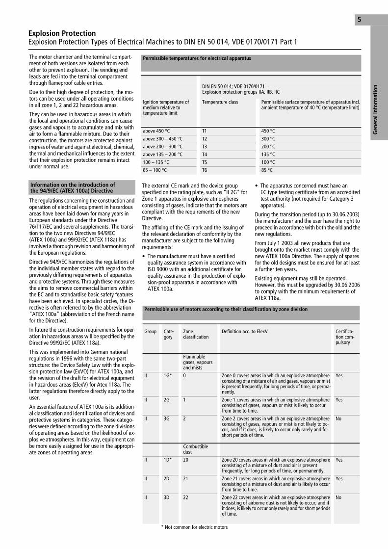
The motor chamber and the terminal compart-ment of both versions are isolated from each other to prevent explosion. The winding end leads are fed into the terminal compartment through flameproof cable entries.
Due to their high degree of protection, the mo-tors can be used under all operating conditions in all zone 1, 2 and 22 hazardous areas.
They can be used in hazardous areas in which the local and operational conditions can cause gases and vapours to accumulate and mix with air to form a flammable mixture. Due to their construction, the motors are protected against ingress of water and against electrical, chemical, thermal and mechanical influences to the extent that their explosion protection remains intact under normal use.
The regulations concerning the construction and operation of electrical equipment in hazardous areas have been laid down for many years in European standards under the Directive 76/117/EC and several supplements. The transi-tion to the two new Directives 94/9/EC (ATEX 100a) and 99/92/EC (ATEX 118a) has involved a thorough revision and harmonising of the European regulations.
Directive 94/9/EC harmonizes the regulations of the individual member states with regard to the previously differing requirements of apparatus and protective systems. Through these measures the aims to remove commercial barriers within the EC and to standardise basic safety features have been achieved. In specialist circles, the Di-rective is often referred to by the abbreviation “ATEX 100a” (abbreviation of the French name for the Directive).
In future the construction requirements for oper-ation in hazardous areas will be specified by the Directive 99/92/EC (ATEX 118a).
This was implemented into German national regulations in 1996 with the same two-part structure: the Device Safety Law with the explo-sion protection law (ExVO) for ATEX 100a, and the revision of the draft for electrical equipment in hazardous areas (ElexV) for Atex 118a. The latter regulations therefore directly apply to the user.
An essential feature of ATEX 100a is its addition-al classification and identification of devices and protective systems in categories. These catego-ries were defined according to the zone divisions of operating areas based on the likelihood of ex-plosive atmospheres. In this way, equipment can be more easily assigned for use in the appropri-ate zones of operating areas.
The external CE mark and the device group specified on the rating plate, such as “II 2G” for Zone 1 apparatus in explosive atmospheres consisting of gases, indicate that the motors are compliant with the requirements of the new Directive.
The affixing of the CE mark and the issuing of the relevant declaration of conformity by the manufacturer are subject to the following requirements:
• The manufacturer must have a certified quality assurance system in accordance with ISO 9000 with an additional certificate for quality assurance in the production of explo-sion-proof apparatus in accordance with ATEX 100a.
• The apparatus concerned must have an EC type testing certificate from an accredited test authority (not required for Category 3 apparatus).
During the transition period (up to 30.06.2003) the manufacturer and the user have the right to proceed in accordance with both the old and the new regulations.
From July 1 2003 all new products that are brought onto the market must comply with the new ATEX 100a Directive. The supply of spares for the old designs must be ensured for at least a further ten years.
Existing equipment may still be operated. However, this must be upgraded by 30.06.2006 to comply with the minimum requirements of ATEX 118a.
Information on the introduction ofthe 94/9/EC (ATEX 100a) Directive
Permissible temperatures for electrical apparatus
DIN EN 50 014; VDE 0170/0171Explosion protection groups IIA, IIB, IIC
Ignition temperature of medium relative to temperature limit
Temperature class Permissible surface temperature of apparatus incl. ambient temperature of 40 °C (temperature limit)
above 450 °C T1 450 °C
above 300 – 450 °C T2 300 °C
above 200 – 300 °C T3 200 °C
above 135 – 200 °C T4 135 °C
100 – 135 °C T5 100 °C
85 – 100 °C T6 85 °C
Permissible use of motors according to their classification by zone division
Group Cate-gory
Zoneclassification
Definition acc. to ElexV Certifica-tion com-pulsory
Flammable gases, vapours and mists
II 1G* 0 Zone 0 covers areas in which an explosive atmosphere consisting of a mixture of air and gases, vapours or mist is present frequently, for long periods of time, or perma-nently.
Yes
II 2G 1 Zone 1 covers areas in which an explosive atmosphere consisting of gases, vapours or mist is likely to occur from time to time.
Yes
II 3G 2 Zone 2 covers areas in which an explosive atmosphere consisting of gases, vapours or mist is not likely to oc-cur, and if it does, is likely to occur only rarely and for short periods of time.
No
Combustible dust
II 1D* 20 Zone 20 covers areas in which an explosive atmosphere consisting of a mixture of dust and air is present frequently, for long periods of time, or permanently.
Yes
II 2D 21 Zone 21 covers areas in which an explosive atmosphere consisting of a mixture of dust and air is likely to occur from time to time.
Yes
II 3D 22 Zone 22 covers areas in which an explosive atmosphere consisting of airborne dust is not likely to occur, and if it does, is likely to occur only rarely and for short periods of time.
No
* Not common for electric motors
Ff01a01g.fm Seite 5 Montag, 17. September 2001 9:41 09
Explosion ProtectionExplosion Protection Types of Electrical Machines to DIN EN 50 014, VDE 0170/0171 Part 1
Gen
eral
Info
rmat
ion
6
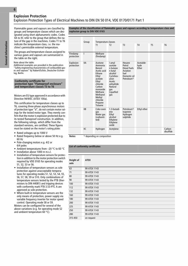
Flammable gases and vapours are classified by groups and temperature classes which are des-ignated using short alphanumeric codes. Codes IIA to IIC refer to the group that defines the na-ture of the gap in the machines. Codes T1 to T6 indicate the temperature class, i.e. the ma-chine’s permissible external temperature.
The groups and temperature classes assigned to various gases and vapours are summarized in the table on the right.
Note about the table:Additional examples are provided in the publication “Safety engineering characteristics of combustible gas-es and vapours” by Nabert/Schön, Deutscher Eichver-lag, Berlin.
Motors are EU type approved in accordance with Directive 94/9/EC (ATEX 100a).
This certification for temperature classes up to T6, covering three-phase asynchronous motors of protection type “d”, do not contain motor rat-ings for the tested motor type. They merely con-firm that the motor is explosion protected due to its tested flameproof construction. In addition, the following ratings, which differ from the standard versions, are certified. These figures must be stated on the motor’s rating plate:
• Rated voltages up to 1000 V• Rated frequency below or above 50 Hz e.g.
60 Hz• Pole-changing motors e.g. 4/2 or
6/4 poles• Ambient temperatures from –20 °C to 60 °C• Installation above 1000 m m.s.l.• Installation of temperature sensors for protec-
tion in addition to the motor protection switch required by VDE 0165 for operating modes S1, S2, S3 or S6.
• Installation of temperature sensors as sole protection against unacceptable tempera-tures for operating modes S1, S2, S3, S4, S5, S6, S7, S8, S9 or S10. Only combinations of temperature sensors tested by the PTB (ther-mistors to DIN 44081) and tripping devices with conformity mark PTB 3.53-PTC A are approved as sole protection.
• Where built-in temperature sensors are the only means of protection, power supply via variable frequency inverter for motor speed control. Operating mode S8 or S9.
Motors can be configured for several of the above variations (e.g. for operating mode S2 and ambient temperature 60 °C).
Examples of the classification of flammable gases and vapours according to temperature class and explosion group to DIN VDE 0165
Group Temperature classesT1 T2 T3 T4 T5 T6
Firedamp protection
I Methane(firedamp)
Explosion protection
IIA AcetoneAmmoniaBenzolAcetic acidEthaneEthyl acetateEthyl chlorideCarbon monoxideMethaneMethanolMethyl chloridePropaneToluene
I amyl acetaten butanen butyl alcoholCyclohex-anonAcetic anhydrideNatural gasLiquefied gas
HexanePetrolDiesel fuelsAviation fuelDomestic oilPetroleum1)
Acetalde-hydeEther
IIB Coke-oven gasWater gas(carburet-ted)
1.3-butadi-eneEthyl alcoholEthyleneEthylene oxide
Petroleum1)
IsopreneHydrogen sulphide
Ethyl ether
IIC Hydrogen Acetylene Carbon disulfide
Notes 1) depending on composition
Conformity certificate for protection type “Flameproof enclosure”and temperature classes T3 to T6
List of conformity certificates
Height of axle
ATEX
63 99 ATEX 1143
71 99 ATEX 1143
80 99 ATEX 1143
90 99 ATEX 1143
100 99 ATEX 1143
112 99 ATEX 1143
132 99 ATEX 1143
160 99 ATEX 1143
180 99 ATEX 1143
200 99 ATEX 1143
225 99 ATEX 1143
250 99 ATEX 1143
280 99 ATEX 1143
315-450 on request
Ff01a01g.fm Seite 6 Montag, 17. September 2001 9:41 09

Explosion ProtectionValidity of European Standard EN 50 014 and Others by Country
7
Gen
eral
Info
rmat
ion
Explosion protection to international specifications.The European standards EN 50 014 to 50 020 are accepted without any changes as a CENELEC standard by all CENELEC member countries. Conformity certificates awarded by the ap-proved testing authorities (in accordance with the EU general guideline for Ex apparatus) in the EU member states are mutually recognized by all other member countries in accordance with the provisions of the Treaty of Rome and the Maas-tricht treaty.
No separate certification from the respective national testing authorities in addition to the conformity certificate is required. Because the European standard is based on IEC publication 60 079, motors designed in accord-ance with EN requirements can also be used in many non-European countries, although some changes may be necessary, e.g. adaptation of the terminal box to specific installation methods.
See also the table of standards and regulations on page 2, 3.
EU Countries Approved EU Ex testing authorities
Germany PTB/BVS/IBExU/... According to the Treaty of Rome and the Maastricht Treaty, EN regulations must be valid in all EU member states, and the conformity certificates issued by EU-approved testing authorities must therefore be recognized by all EU members. Accordingly, electrical apparatus approved for use on the basis of conformity and EC type testing certificates can be supplied without restriction to the countries mentioned in the first column.
Greece
Luxembourg SEE
Portugal
Iceland
Great Britain & Northern Ireland EECS/SCS
Belgium ISSEP
France INERIS/LCIE
Ireland
The Netherlands KEMA
Italy CESI
Denmark DEMKO
Spain LOM
Finland VTT
Norway NEMKO
Austria TÜV-A/BVFA
Sweden SP
CENELEC countries National testing authority
Switzerland SEV The national regulations of the non-EU CENELEC countries are based on EN specifications so that the level of explosion protection of EN-compliant equipment is known in those countries. In many cases, the national testing authorities recognize the conformity certification and will issue national certification on its basis. In some cases, additional national requirements may have to be met, for example adaptation of the terminal box. Type approval certification based on Directive 94/9/EC is accepted without retesting.
Ff01a01g.fm Seite 7 Montag, 17. September 2001 9:41 09

Construction Types
Des
ign
Type
s8
Up to frame size 355 – any number of poles – the motor bearings are designed so that they can be used as described below without modifi-cation.
IM B3 as IM B6, IM B7, IM B8, IM V5*, IM V6*IM B5 as IM V1*, IM V3*IM B35 as IM V15*, IM V36*IM B14 as IM V18, IM V19
Exception: For the vertical design types marked *, protective devices must be fitted to provide protection against dripping water and to prevent foreign bodies from falling into the units.
H.V. (high-voltage) motors are available only in construction types IM B3, B35 and V1.
Available construction types to DIN IEC 34, Part 7 (replaces DIN 42950,04.64)Other construction types are available on request
IEC Code I IM B3 IM B35 IM B5 IM B6 IM B7
IEC Code II IM1001 IM2001 IM3001 IM1051 IM1061
Explanation Foot mounting, feet at bottom
Foot mounting, feet at bottom, with addi-tional flange mounting; access from housing side
Flange bearing plate on drive side, access from housing side
Foot mounting, feet on left side (viewed from drive side)
Foot mounting, feet on right side (viewed from drive side)
IEC Code I IM B8 IM V1 IM V3 IM V5 IM V6
IEC Code II IM1071 IM3011 IM3031 IM1011 IM1031
Explanation Foot mounting, feet on top Flange mounting on drive end of flange; access from housing side, drive shaft at bottom
Flange mounting on drive end of flange; access from housing side, drive shaft at top
Foot mounting, drive shaft at bottom
Foot mounting, drive shaft at top
IEC Code I IM B14 IM V18 IM V19 IM B34 IM V15/IM V36
IEC Code II IM3601 IM3611 IM3631 IM2101 IM2111/2131
Explanation Flange mounting on drive end of flange; no access from housing side
Flange mounting on drive end of flange; no access from housing side, drive shaft at bottom
Flange mounting on drive end of flange; no access from housing side, drive shaft at top
Foot mounting, feet at bot-tom, with additional flange mounting on drive end of flange. No access from housing side
Foot mounting with addi-tional flange mounting on drive end of flange. Drive shaft at bottom or top. With or without access from housing side.
Ff01a02g.fm Seite 8 Montag, 17. September 2001 9:44 09

Des
ign
Type
s
Materials, Plates and LabellingFor Casings, End Shields, Terminal Boxes and Fans
9
Rating and test information is contained on a single plate attached to the housing. A duplicate is attached to the inside of the EEx e terminal box lid. The plates are made of stainless steel (material 1.4300).
Materials for casings, end shields, terminal boxes and fans
Frame size Housing type End shield Terminal box Fan cowl Radial-flow fan Axial-flow fan
Material Feet EEx e EEx d 2-pole 4, 6, 8-pole
63 Grey cast iron Grey cast iron, bolted
Grey cast iron Grey cast iron, bolted
Grey cast iron, bolted
n/a n/a n/a
71 Sheet steel Plastic1) Plastic1)
80
90
100
112
132 Plastic
160
180
200
225 Cast alumini-um alloyHub in grey cast iron 20
Cast alumini-um alloyHub in grey cast iron 20
250
280
315
355 Steel, welded Steel, welded Steel, welded
400 Steel, welded Steel, welded
450
Notes 1) For special operating conditions (e.g. low temperatures) fans made of cast aluminium alloy can also be supplied for frame sizes 63 to 200.
Plates and labels
Ff01a02g.fm Seite 9 Montag, 17. September 2001 9:44 09

Installation at Normal and Low Temperatures
Des
ign
Type
s10
The standard motors are suitable for installation outdoors, in humid and dusty atmospheres (industrial climate) at temperatures of –20 °C to +40 °C.
Motors suitable for use at extremely low temperatures are designed in accordance with the table on the right.
The test certification from the German Federal Institute of Physics and Metrology (PTB) is a valid for below-zero temperatures down to –20 °C. At lower temperatures, anti-condensa-tion heaters must be used, for example to heat the motors from –40 °C to –20 °C.
Designs up to –55 °C without anti-condensation heating on request.
Motors intended for on-board or offshore installation conform to the regulations of the respective classification authorities. To ensure safe on-deck installation, the motors have a series of additional design features (see page 20). These motors are prototype test certified by Germanischer Lloyd.
Use at low temperatures
Component –20 °C –40 °C –55 °C
Bearing Normal Normal Normal
Bearing grease SRI2 SRI2 SRI2
Shaft seal Normal Normal Special
Fan Normal Aluminium fan Aluminium fan
Stator winding Normal Normal Normal
Anti-condensation heater No Required Required
Cast parts Grey cast iron 20 Grey cast iron 20 Grey cast iron 20
Fastening screws 8.8 8.8 8.8
Paintwork Normal Normal Special
Ff01a02g.fm Seite 10 Montag, 17. September 2001 9:44 09
Protection Types, Paintwork
Des
ign
Type
s
11
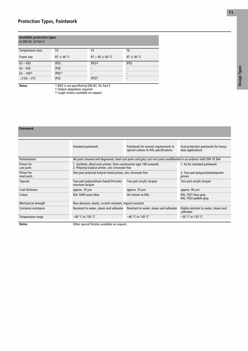
Available protection typesto DIN IEC 34 Part 5
Temperature class T4 T4 T6
Frame size RT
F 40 °C RT > 40
F 60 °C RT
F 40 °C
63 – 450 IP55 IP552) IP55
63 – 450 IP56 – –
63 – 1603) IP651) – –
...X 63 – 315 IP55 IP552) –
Notes 1) IP65 is not specified by DIN IEC 34, Part 52) Output adaptation required3) Larger motors available on request
Paintwork
Standard paintwork Paintwork for normal requirements in special colours to RAL specifications
Acid protection paintwork for heavy-duty applications
Pretreatment All parts cleaned and degreased, steel cast parts and grey cast iron parts sandblasted in accordance with DIN 18 364
Primer forcast parts
1. Synthetic alkyd resin primer, from construction type 160 onwards.2. Polyvinyl butyral primer, zinc chromate free
1. As for standard paintwork
Primer forsteel parts
One-part polyvinyl butyral metal primer, zinc chromate free 2. Two-part polyacrylate/polyester primer
Topcoat Two-part polyurethane based Percotex structure lacquer
Two-part acrylic lacquer Two-part acrylic lacquer
Coat thickness approx. 70
mm approx. 70
mm approx. 90
mm
Colour RAL 5009 azure blue All colours to RAL RAL 7031 blue-greyRAL 7032 pebble-grey
Mechanical strength Non-abrasive, elastic, scratch-resistant, impact-resistant
Corrosion resistance Resistant to water, steam and saltwater Resistant to water, steam and saltwater Highly resistant to water, steam and saltwater
Temperature range –40 °C to 130 °C –40 °C to 130 °C –50 °C to 130 °C
Notes Other special finishes available on request.
Ff01a02g.fm Seite 11 Montag, 17. September 2001 9:44 09

Terminal Boxes
Des
ign
Type
s12
The terminal boxes are protected to EEx d IIC as defined by EN 50 018 or to EEx e II (Increased safety) as defined by EN 50 019 and to IP56 as defined by DIN EN 60 034 Part 5.
The cable entries used on the terminal boxes conform to the respective protection type and are fitted with an oil-resistant cover seal. The cover fixing screws are corrosion-protected and captive (except on H.V. motors).
The terminal box is fitted to the top of the machine. From frame size 63, they can be rotated by 4
x 90 degrees to enable connection from all directions. From frame size 132, this can be achieved without rotating the connection plate.
The terminal boxes with version 8 cable glands are an exception, and can be rotated by 180°.
The winding end leads are fed into the terminal compartment through flameproof cable entries.
For L.V. motors, a multiple penetration or single penetration systems are used for AC voltages up to at least 690 V.
Special versions for 1000 V are also available at extra cost.
H.V. motors are fitted with single penetration systems according to the rated voltage.For frame sizes 315 – 450, the terminals for connection without cable lugs are placed directly on the penetration bolts.Where built-in temperature sensors are fitted, additional terminals are available in the terminal box.
H.V. motors have an additional terminal compartment.
the terminal boxes of the L.V. motors have metric threads to DIN 42 925 with cable entries to DIN EN 50 262.
For frame size 180 and above, the terminal boxes are equipped with a screw-on plate for optional installation of screw glands, cable glands or a split cable entry gland.
From frame size 250, longitudinally split terminal boxes are also available.
An additional terminal box for thermal monitoring or anti-condensation heaters is also available from frame size 180. It is bolted to the motor connection box or, on frame sizes 355 to 450, fitted to the housing.
The H.V. motor terminal boxes conform to DIN 42 962. On request, the star point can be located in a second terminal box. The terminal box is protected to EEx e II (Increased safety), as defined by EN 50 019 and are supplied in version 9.
The various cable entry components (extra-cost option) and their thread sizes are listed in the table on page 13.
Protection type
Position and rotatability
Power line bushings and terminals Terminal box – standard EEx e version
Frame sizes 63 – 112 Frame sizes 132 – 160 Frame sizes 180 – 280Frame size 315 with bolt-type gland
Frame sizes 250 – 450Frame sizes 250 and 280 with connection plate, as for frame sizes 180 – 280
Version 1Cable entryto DIN EN 50 014(screw gland)for fixed cables
Version 3Cable entry glands toEN 50 014, with strain relief, anti-rotation and anti-kink devices for cable of mobile apparatus
Version 8Split cable entry with internal strain relief clamp
Version 9Split terminal box with the internal strain relief clamp
Ff01a02g.fm Seite 12 Montag, 17. September 2001 9:44 09
Des
ign
Type
s
Terminal Boxes
13
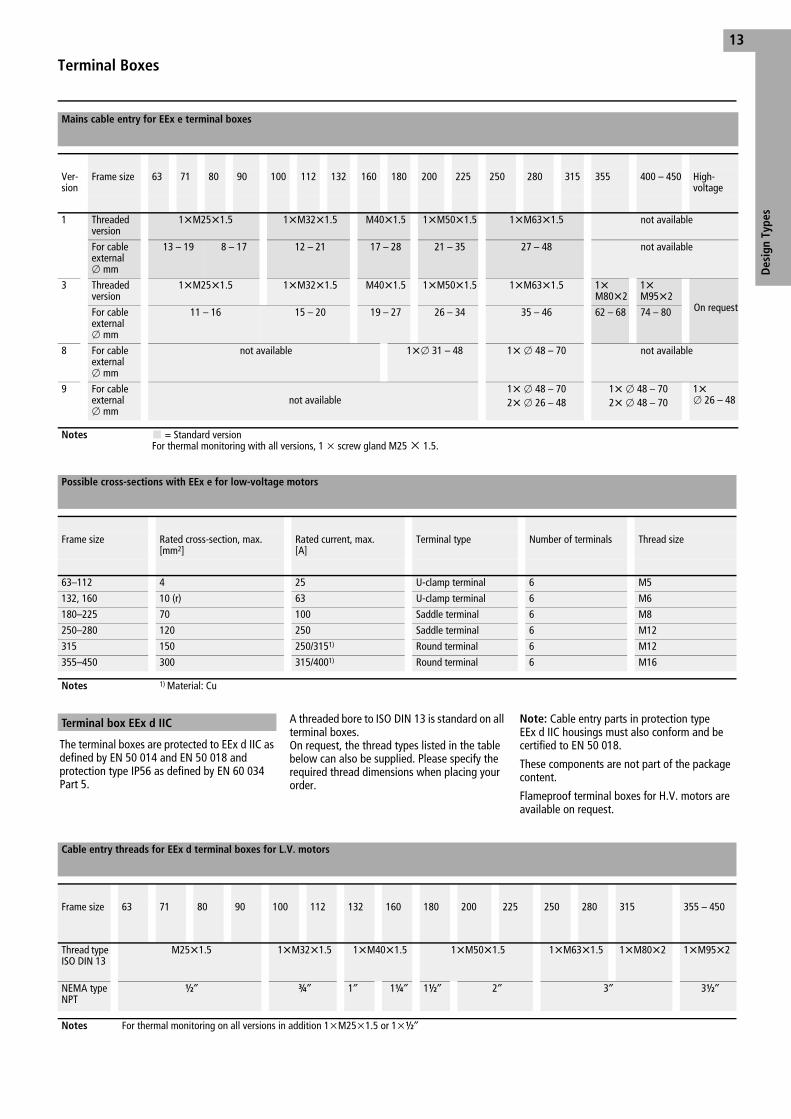
The terminal boxes are protected to EEx d IIC as defined by EN 50 014 and EN 50 018 and protection type IP56 as defined by EN 60 034 Part 5.
A threaded bore to ISO DIN 13 is standard on all terminal boxes.On request, the thread types listed in the table below can also be supplied. Please specify the required thread dimensions when placing your order.
Note: Cable entry parts in protection type EEx d IIC housings must also conform and be certified to EN 50 018.
These components are not part of the package content.
Flameproof terminal boxes for H.V. motors are available on request.
Mains cable entry for EEx e terminal boxes
Ver-sion
Frame size 63 71 80 90 100 112 132 160 180 200 225 250 280 315 355 400 – 450 High-voltage
1 Threaded version
1
XM25
X1.5 1
XM32
X1.5 M40
X1.5 1
XM50
X1.5 1
XM63
X1.5 not available
For cable external
o mm
13 – 19 8 – 17 12 – 21 17 – 28 21 – 35 27 – 48 not available
3 Threaded version
1
XM25
X1.5 1
XM32
X1.5 M40
X1.5 1
XM50
X1.5 1
XM63
X1.5 1
XM80
X21
XM95
X2On requestFor cable
external
o mm
11 – 16 15 – 20 19 – 27 26 – 34 35 – 46 62 – 68 74 – 80
8 For cable external
o mm
not available 1
X
o 31 – 48 1
X
o 48 – 70 not available
9 For cable external
o mmnot available
1
X
o 48 – 702
X
o 26 – 481
X
o 48 – 702
X
o 48 – 701
X
o 26 – 48
Notes = Standard versionFor thermal monitoring with all versions, 1
x screw gland M25
x 1.5.
Possible cross-sections with EEx e for low-voltage motors
Frame size Rated cross-section, max. [mm2]
Rated current, max.[A]
Terminal type Number of terminals Thread size
63–112 4 25 U-clamp terminal 6 M5
132, 160 10 (r) 63 U-clamp terminal 6 M6
180–225 70 100 Saddle terminal 6 M8
250–280 120 250 Saddle terminal 6 M12
315 150 250/3151) Round terminal 6 M12
355–450 300 315/4001) Round terminal 6 M16
Notes 1) Material: Cu
Terminal box EEx d IIC
Cable entry threads for EEx d terminal boxes for L.V. motors
Frame size 63 71 80 90 100 112 132 160 180 200 225 250 280 315 355 – 450
Thread type ISO DIN 13
M25
X1.5 1
XM32
X1.5 1
XM40
X1.5 1
XM50
X1.5 1
XM63
X1.5 1
XM80
X2 1
XM95
X2
NEMA type NPT
M
j
O
j 1
j 1
K
j 1
M
j 2
j 3
j 3
M
j
Notes For thermal monitoring on all versions in addition 1
xM25
x1.5 or 1
x
M
j
Ff01a02g.fm Seite 13 Montag, 17. September 2001 9:44 09
Connection CablesFor Motors With Direct Cable Connection
Des
ign
Type
s14
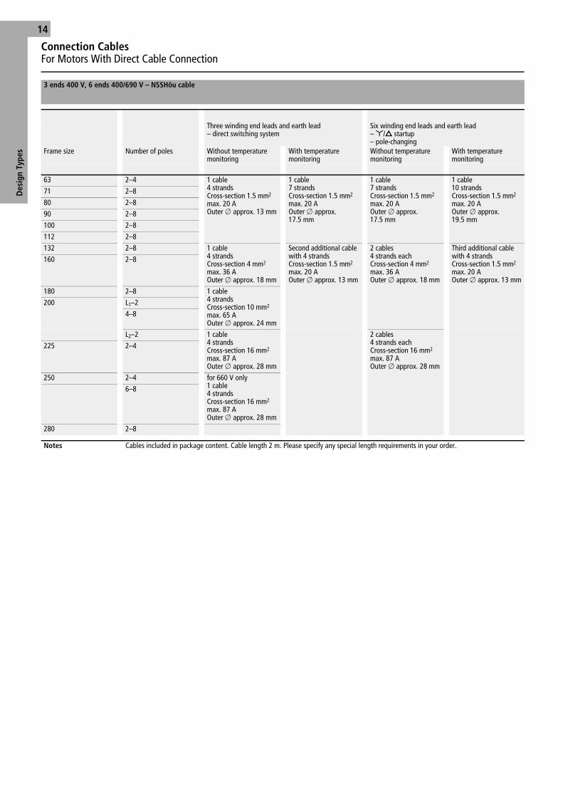
3 ends 400 V, 6 ends 400/690 V – NSSHöu cable
Three winding end leads and earth lead – direct switching system
Six winding end leads and earth lead–
Y/
D startup– pole-changing
Frame size Number of poles Without temperature monitoring
With temperature monitoring
Without temperature monitoring
With temperature monitoring
63 2–4 1 cable4 strandsCross-section 1.5 mm2
max. 20 AOuter
o approx. 13 mm
1 cable7 strandsCross-section 1.5 mm2
max. 20 AOuter
o approx. 17.5 mm
1 cable7 strandsCross-section 1.5 mm2
max. 20 AOuter
o approx. 17.5 mm
1 cable10 strandsCross-section 1.5 mm2
max. 20 AOuter
o approx. 19.5 mm
71 2–8
80 2–8
90 2–8
100 2–8
112 2–8
132 2–8 1 cable4 strandsCross-section 4 mm2
max. 36 AOuter
o approx. 18 mm
Second additional cable with 4 strandsCross-section 1.5 mm2
max. 20 AOuter
o approx. 13 mm
2 cables4 strands eachCross-section 4 mm2
max. 36 AOuter
o approx. 18 mm
Third additional cable with 4 strandsCross-section 1.5 mm2
max. 20 AOuter
o approx. 13 mm
160 2–8
180 2–8 1 cable4 strandsCross-section 10 mm2
max. 65 AOuter
o approx. 24 mm
200 L1–2
4–8
L2–2 1 cable4 strandsCross-section 16 mm2
max. 87 AOuter
o approx. 28 mm
2 cables4 strands eachCross-section 16 mm2
max. 87 AOuter
o approx. 28 mm
225 2–4
250 2–4 for 660 V only1 cable4 strandsCross-section 16 mm2
max. 87 AOuter
o approx. 28 mm
6–8
280 2–8
Notes Cables included in package content. Cable length 2 m. Please specify any special length requirements in your order.
Ff01a03g.fm Seite 14 Montag, 17. September 2001 9:45 09

Bearings
15
Des
ign
Type
s
The motors are fitted with external radial or axial seals. Vertical construction types with upward-facing shaft are fitted with a combined radial and axial seal. The seals prevent ingress of water along the shaft into the bearing housing. They have good abrasion resistance and thermal stability and are also resistant to mineral oils, saline solutions and diluted acids.Seals for media not listed above are available on request.
The bearings of motors up to frame size 280 have lifetime lubrication. The deep-groove ball bearings, which are sealed on both sides, are pre-packed with polyurea fibre grease by the bearing manufacturer. They are therefore maintenance-free for the time specified in the upper table on page 18.
From frame size 315, motors are equipped with relubrication devices with grease distributors. Relubrication devices are also fitted to motors from frame size 225 that are equipped with roller bearings for heavy loads.
Bearings with relubrication devices are packed with lithium-saponified grease. The relubrica-tion intervals are listed in the middle table on page 18.
For vertical construction types (V type), halve the relubrication times.
Always regrease bearings with the same grease type, i.e. grease with the same saponification component and the same consistency. We uses a lithium-saponified anti-friction roller bearing grease with a drop point above 185 °C (e.g. Esso Unirex N 3). See also information plate on mo-tor.
The collecting chamber in the bearing cover is large enough to contain the used grease accu-mulating during normal service life. Flat grease nipples to DIN 3404 with thread size M10
X 1 are used for lubrication.
Bearing-type codes:
Example: 6315.2ZR.L12.C3
6315 = Bearing size
2 ZR = Non-rubbing double seal
L12 = Polyurea fibre grease
C3 = Bearing clearance
Up to frame size 315, a locating bearing is used at the drive-end.
In pure coupling operation, the theoretical serv-ice life is more than 50,000 operating hours.
In the maximum permissible radial and axial loads are given in the tables on pages 16 and 17. The calculations are based on roller bearings with a service life of 20,000 hours. Drives with a higher radial load such as belt drives can be supplied with roller bearings for an additional charge. The minimum radial load specified must be maintained in order to ensure that the bearings roll correctly. For higher axial bearing loads such as occurring with helical gear, special solutions are available on request.
Bearing classification, frame sizes 63 – 450
Drive-end bearings All construction types
Non-drive-end bearing
Type Number of poles
Standard Reinforced bearings Min. load[N]
All construction types
63 2, 4 6202 2ZR – – 6004 2ZR
71 2, 4, 6, 8 6202 2ZR – – 6004 2ZR
80 2, 4, 6, 8 6204 2ZR – – 6204 2ZR
90 2, 4, 6, 8 6205 2ZR – – 6205 2ZR
100 2, 4, 6, 8 6206 2ZR C3 – – 6206 2ZR C3
112 2, 4, 6, 8 6306 2ZR C3 21306 CC/C3 1050 6206 2ZR C3
132 2, 4, 6, 8 6308 2ZR C3 21308 CC/C3 1580 6308 2ZR C3
160 2, 4, 6, 8 6309 2ZR C3 21309 E/C3 1880 6309 2ZR C3
180 2, 4, 6, 8 6310 2ZR C3 21310 E/C3 Explorer 2660 6310 2ZR C3
200 2, 4, 6, 8 6312 2ZR C3 21312 E/C3 Explorer 3310 6312 2ZR C3
225 2, 4, 6, 8 6313 2ZR C3 21313 E/C3 Explorer 3770 6313 2ZR C3
250 2, 4, 6, 8 6315 2ZR C3 21315 E/C3 Explorer 4860 6313 2ZR C3
280 2, 4, 6, 8 6316 2ZR C4 21316 E/C3 Explorer 5470 6315 2ZR C3
315 24, 6, 8
6316 C46318 C4
21316 E/C3 Explorer21318 E/C3 Explorer
54507470
6316 C46316 C4
355 2 6318 C4 NU 318 C3 3710 6318 C4
355 4, 6, 8 6320 C3 NU 320 4440 6320 C3
Construc- Construction typeB3, B5 V1, V3
400 2 6318 C4 NU 318 C3 4570 6318 C4 7316 B +6316 C4
400 4, 6, 8 6322 C3 NU 322 6420 6322 C3 7322 B +6322 C3
450 4, 6, 8 6324 C3 NU 324 7560 6322 C3 7322 B +6322 C3
Bearing seals
Lubrication
Relubrication device, relubrication intervals
Nominal service life
Ff01a03g.fm Seite 15 Montag, 17. September 2001 9:45 09
Permissible Radial Bearing Load
Des
ign
Type
s16
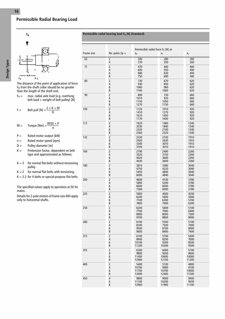
The distance of the point of application of force FR from the shaft collar should be no greater than the length of the shaft end.FR = max. radial axle load (e.g. overhung
belt load + weight of belt pulley) [N]
F = Belt pull [N] =
M = Torque [Nm] =
P = Rated motor output [kW]n = Rated motor speed [rpm]D = Pulley diameter [m]K = Pretension factor, dependent on belt
type and approximated as follows:
K = 3 for normal flat belts without tensioning pulley
K = 2 for normal flat belts with tensioning K = 2.2 for V-belts or special-purpose flat belts
The specified values apply to operation at 50 Hz mains.
Details for 2-pole motors of frame size 400 apply only to horizontal shafts.
Permissible radial bearing load FR [N] (Standard)
Permissible radial force FR [N] atFrame size No. poles 2p = x0 x1 x2
63 24
300370
280350
260260
71 2468
470600680750
440550630690
400400400400
80 2468
730930
10601160
670850960
1060
620620620620
90 2468
800101011501270
730920
10501150
660660660660
100 2468
1120141016101770
1010127014501600
920920920920
112 2468
1620203023202560
1460184021002320
1340134013401340
132 2468
2330292033403700
2100263030103010
1910191019101910
160 2468
2790352040204430
2490315036003600
2260226022602260
180 2468
3810475054506000
3380422048404840
3040304030403040
200 2468
4600580066007300
4100520060006000
3780378037803780
225 2468
5000620071007800
4600560063007000
4200500057006300
250 2468
6200770089009700
5600700080008800
5100640073008000
280 2468
6100820095009600
5500750087008400
5100700080007400
315 2468
61008900
1010011200
570082009200
10300
5400760085009500
355 2468
63009800
1140012900
60009200
1060012100
57008600
1000011300
400 2468
5400107001170013400
51009900
1070012400
48009100
1000011500
450 468
98001110012900
90001020011900
84009500
11100
2 K M××D
-----------------------
9550 P×n
--------------------
Ff01a03g.fm Seite 16 Montag, 17. September 2001 9:45 09

Des
ign
Type
s
Permissible Axial Bearing Load
17
Permissible axial bearing load FA [N] (Standard)
For construction types Frame size 3000 rpmLoad to
1500 rpmLoad to
1000 rpmLoad to
750 rpmLoad to
m N
l N
m N
l N
m N
l N
m N
l N
IM B3, IM B5, IM B35 63 170 300 200 350 – – – –
71 160 320 200 400 250 500 320 560
80 700 500 900 700 1000 800 1100 1000
90 700 500 900 800 1100 900 1200 1000
100 900 800 1200 1100 1400 1300 1600 1500
112 1300 1200 1800 1600 2100 1900 2300 2200
132 2100 1600 2600 2200 3100 2700 3500 3000
160 2600 2000 3400 2800 3900 3400 4400 3800
180 1900 2600 2330 3210 2900 3780 3340 4220
200 2500 3300 3150 4100 3850 4800 4350 5350
225 4000 2650 5000 3200 5650 3950 6300 4600
250 4100 5600 5700 7200 6800 8300 7700 9300
280 4700 6500 7100 8900 7200 9000 8100 9900
315 4900 6900 6400 8400 7600 9600 8800 10800
355 8100 4500 10200 6600 11700 8100 13200 9600
400 5000 1800 4700 4700 5400 5400 6300 6300
450 – – 4500 4500 4800 4800 5500 5500
L N
M N
L N
M N
L N
M N
L N
M N
IM V1, IM V5, IM V15 63 170 320 220 400 – – – –
71 240 360 190 460 250 530 300 570
80 600 500 800 700 1000 900 1100 1000
90 700 600 900 800 1000 1000 1200 1100
100 900 900 1200 1200 1400 1400 1500 1600
112 1300 1300 1600 1800 1900 2100 2200 2300
132 1900 1800 2400 2500 2900 3000 3300 3300
160 2300 2400 3000 3300 3500 3900 3900 4400
180 1650 2900 1890 3780 2390 4410 2840 4930
200 2100 3800 2500 4900 3150 5600 3600 6350
225 3500 3250 4050 4200 4700 5150 5300 5800
250 3200 6700 4500 8800 5500 10100 6200 11300
280 3600 8200 5300 11300 5400 11400 6000 12900
315 2700 9900 2900 13000 3400 15400 4300 16800
355 4000 10200 3900 15000 4900 17400 6300 18800
400 6800 1390 6600 20700 6500 24900 8200 26700
450 – – 5400 22700 3700 26500 4500 29100
L N
M N
L N
M N
L N
M N
L N
M N
IM V3, IM V6, IM V36 63 300 180 380 230 – – – –
71 340 170 430 220 490 290 540 340
80 500 700 700 900 800 1100 900 1200
90 500 800 700 1000 800 1200 1000 1300
100 800 1000 1000 1300 1200 1600 1400 1700
112 1100 1400 1500 1900 1800 2200 2100 2500
132 1500 2200 2000 2900 2400 3400 2800 3700
160 1800 3000 2500 3800 3000 4500 3400 4900
180 1650 2200 2770 2900 3280 3530 3660 4030
200 2850 3000 3450 3900 4150 4650 4600 5350
225 2100 4650 2250 5600 2950 7050 3600 7550
250 4800 5200 6000 7200 7000 8600 7800 9800
280 5400 6400 7100 9500 7200 9600 7800 11100
315 4700 7900 4900 11000 5400 13400 6300 14800
355 400 13800 300 18600 1300 21000 2700 22400
400 3600 13900 6600 20700 6500 24900 8200 26700
450 – – 5400 22700 3700 26600 4500 29100
Ff01a03g.fm Seite 17 Montag, 17. September 2001 9:45 09

Lubrication, Shaft Ends, Running Smoothness, Operating Noise Levels
Des
ign
Type
s18
The motors normally have a free shaft end whose dimensions conform to DIN 748 Part 3, DIN 42 672 and DIN 42 673.
From frame size 63, the shaft ends have an inter-nal thread to DIN 332 Form “D”. The feather-keys are designed to DIN 6885 Sh. 1.
Motors with special shafts and/or a second shaft end are available on request at extra cost (does not apply to motors with axial fan and motors with attachments at the non-drive end, e.g. tachometer).
The motors are dynamically balanced to vibra-tion intensity level “N” (normal) with half featherkeys to DIN VDE 0530 Part 14.
Special variants, balanced with a full featherkey are an extra-cost option.
In conformance with DIN ISO 8821, the motors’ shaft end faces are marked as follows:
H = Half-featherkey balancing
F = Full-featherkey balancing
For applications requiring exceptional mechani-cal running smoothness, a low-vibration variant “R” (reduced) or vibration intensity level “S” (special) is available at extra cost.
Noise measurements are performed in a dead room to DIN 45 635.
The sound pressure level Lp and the sound power level Lw in dB(A) for each frame size are listed on the operating data sheets.
These readings conform to DIN EN 21 680-1 and were taken at nominal load at 50 Hz plus the +3 dB(A) tolerance permitted by VDE 0530.
For available variants of low-noise motors, see page 19.
Maintenance-free service life with relubrication and coupling operation
Motors with standard outputcoupling operation
Motors with increased outputcoupling operation
Frame size Number of poles RT 40 °C Frame size Number of poles RT 40 °C
63 – 71 2 20000 h 63 – 71 2 20000 h
4, 6, 8 40000 h 4, 6, 8 40000 h
80 – 90 2 20000 h 80 – 90 2 15000 h
4, 6, 8 40000 h 4, 6, 8 30000 h
100 – 132 2 20000 h 100 – 132 2 10000 h
4, 6, 8 40000 h 4, 6, 8 20000 h
160 – 280 2 20000 h 160 – 280 2 7500 h
4, 6, 8 40000 h 4, 6, 8 15000 h
Relubrication intervals for horizontal construction type
Motors with standard outputRelubrication interval
Motors with increased outputRelubrication interval
Speed Speed
Room temperature up to 1800 rpm up to 3600 rpm up to 1800 rpm up to 3600 rpm
40 °C 5000 h 2500 h 5000 h 2500 h
50 °C 2500 h 1000 h 2500 h 1000 h
60 °C 2000 h 500 h - -
Shaft ends Balancing, running smoothness
Frame sizeLevel N 63 – 132 160 – 225 250 – 450veff [mm/s] 1.8 2.8 4.5
Operating noise levels
Ff01a03g.fm Seite 18 Montag, 17. September 2001 9:45 09

Special-Purpose MotorsLow-Noise Motors
19
Des
ign
Type
s
As result of extensive experience and intensive development work in the field of noise reduction for electrical machines, we have developed motors that contribute significantly to reducing noise levels. Focusing on low sound radiation, this aim has been achieved with design features such as a solid, low-vibration construction, an optimized magnetic layout, an effective cooling system and tight machining tolerances.
In the standard version, bi-directional radial-flow fans with broad, shallow blades are used. They are capable of conveying large volumes of air efficiently and at low noise levels.
For more exacting requirements, we recommend the low-noise variant with its unidirectional axial-flow fan. These fans can be fitted to 2-pole motors of frame size 132 and above and 4-pole motors of frame size 180 and above. For 2-pole motors, the aerodynamic shape and optimized angle of attack of the fan blades results in a noise reduction of up to 10 dB(A) compared to the standard version. At the same time, the motor’s efficiency is increased due to the fan’s reduced power consumption.
Low-noise motors Noise class 1Standard version
Noise class 2Axial-flow fans, low-noise
Ff01a03g.fm Seite 19 Montag, 17. September 2001 9:45 09
Special-Purpose MotorsOn-Deck Installation by Shipping Classification
Des
ign
Type
s20
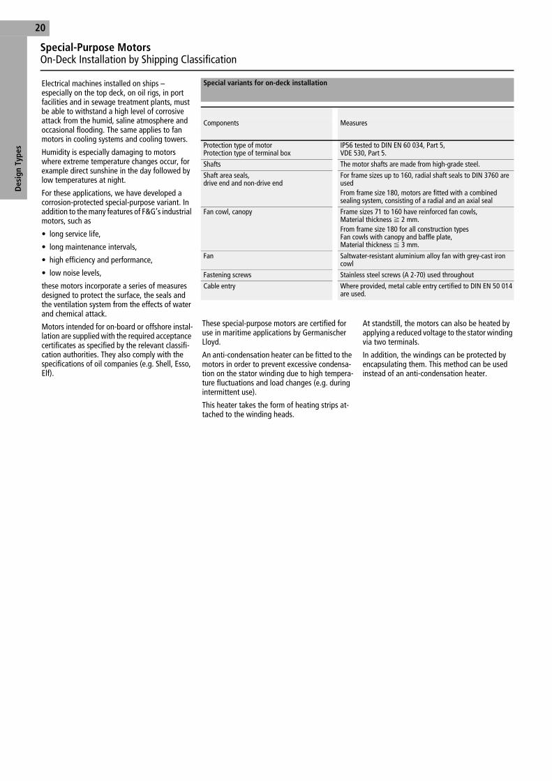
Electrical machines installed on ships – especially on the top deck, on oil rigs, in port facilities and in sewage treatment plants, must be able to withstand a high level of corrosive attack from the humid, saline atmosphere and occasional flooding. The same applies to fan motors in cooling systems and cooling towers.
Humidity is especially damaging to motors where extreme temperature changes occur, for example direct sunshine in the day followed by low temperatures at night.
For these applications, we have developed a corrosion-protected special-purpose variant. In addition to the many features of F&G’s industrial motors, such as
• long service life,
• long maintenance intervals,
• high efficiency and performance,
• low noise levels,
these motors incorporate a series of measures designed to protect the surface, the seals and the ventilation system from the effects of water and chemical attack.
Motors intended for on-board or offshore instal-lation are supplied with the required acceptance certificates as specified by the relevant classifi-cation authorities. They also comply with the specifications of oil companies (e.g. Shell, Esso, Elf).
These special-purpose motors are certified for use in maritime applications by Germanischer Lloyd.
An anti-condensation heater can be fitted to the motors in order to prevent excessive condensa-tion on the stator winding due to high tempera-ture fluctuations and load changes (e.g. during intermittent use).
This heater takes the form of heating strips at-tached to the winding heads.
At standstill, the motors can also be heated by applying a reduced voltage to the stator winding via two terminals.
In addition, the windings can be protected by encapsulating them. This method can be used instead of an anti-condensation heater.
Special variants for on-deck installation
Components Measures
Protection type of motorProtection type of terminal box
IP56 tested to DIN EN 60 034, Part 5,VDE 530, Part 5.
Shafts The motor shafts are made from high-grade steel.
Shaft area seals,drive end and non-drive end
For frame sizes up to 160, radial shaft seals to DIN 3760 are used From frame size 180, motors are fitted with a combined sealing system, consisting of a radial and an axial seal
Fan cowl, canopy Frame sizes 71 to 160 have reinforced fan cowls, Material thickness f 2 mm.From frame size 180 for all construction types Fan cowls with canopy and baffle plate,Material thickness F 3 mm.
Fan Saltwater-resistant aluminium alloy fan with grey-cast iron cowl
Fastening screws Stainless steel screws (A 2-70) used throughout
Cable entry Where provided, metal cable entry certified to DIN EN 50 014 are used.
Ff01a04g.fm Seite 20 Montag, 17. September 2001 9:45 09
Special-Purpose MotorsOn-Deck Installation by Shipping Classification
21
Des
ign
Type
s
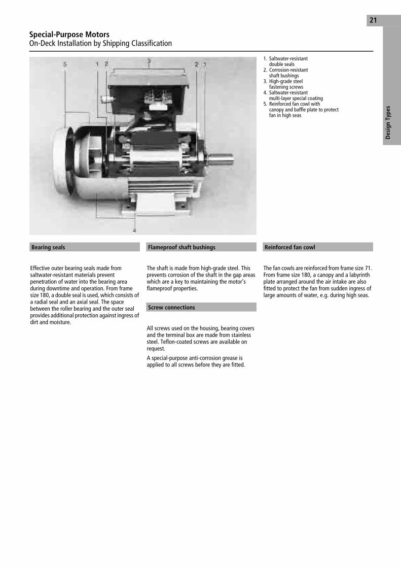
1. Saltwater-resistant double seals
2. Corrosion-resistant shaft bushings
3. High-grade steel fastening screws
4. Saltwater-resistant multi-layer special coating
5. Reinforced fan cowl with canopy and baffle plate to protect fan in high seas
Effective outer bearing seals made from saltwater-resistant materials prevent penetration of water into the bearing area during downtime and operation. From frame size 180, a double seal is used, which consists of a radial seal and an axial seal. The space between the roller bearing and the outer seal provides additional protection against ingress of dirt and moisture.
The shaft is made from high-grade steel. This prevents corrosion of the shaft in the gap areas which are a key to maintaining the motor’s flameproof properties.
All screws used on the housing, bearing covers and the terminal box are made from stainless steel. Teflon-coated screws are available on request.
A special-purpose anti-corrosion grease is applied to all screws before they are fitted.
The fan cowls are reinforced from frame size 71. From frame size 180, a canopy and a labyrinth plate arranged around the air intake are also fitted to protect the fan from sudden ingress of large amounts of water, e.g. during high seas.
Bearing seals Flameproof shaft bushings
Screw connections
Reinforced fan cowl
Ff01a04g.fm Seite 21 Montag, 17. September 2001 9:45 09

Special-Purpose MotorsSpecial Attachments, Special Flanges
Des
ign
Type
s22
Motors are designed to cover a wide range of applications. To meet the special requirements associated with each of these uses, a series of special attachments has been developed.
These attachments allow inexpensive fitting of brakes, tachometers, pulse generators and reverse running locks.
To ensure that its motors are suitable for a wide range of applications, we have a range of special flanges that goes far beyond of the mounting dimensions for construction types IM B5 and IM B14 as defined by DIN 42 677. The flanges listed can be supplied without any additional modifications of the motor. See table on the right. From frame size 180, the standard flanges (see page 54) are available. Intermediate rings are used for special mounting dimensions (on request).
x = Standard
k = Special flange (extra cost option)
All other versions require an intermediate ring (extra cost option).
Motors with special attachments and flanges
Available flanges
Frame size A flanges, o in mm C flanges, o in mm120 140 160 200 250 300 350 80 90 105 120 140 160 200
63 k x k k k k k k x k x k k k
71 k k x k k k k k x k x k k
80 k k k x k k k x k x k
90 k k x k k k x x k
100 k k x k k x x
112 k x k k k x
132 k x k k
160 k x
Special-purpose flanges
Ff01a04g.fm Seite 22 Montag, 17. September 2001 9:45 09
Elec
tric
al L
ayou
t
Electrical DesignFor Motors up to 690 V
23
The explosion-proof, flameproof three-phase asynchronous motors are generally available for standard voltages to DIN IEC 38 (5.87) with the following rated voltages:
All materials used for insulation of the winding and the winding end leads comply with insula-tion class F.
Utilization of the overtemperature limit in con-tinuous operation S1 corresponds to thermal class B for constant-speed motors.
Motors with increased performance and pole-switching motors are utilized in accordance with thermal class F.
The limit temperature thermal class F to VDE 0530 is 105 °C.
The limit overtemperature for the winding insu-lated to thermal class F, according to VDE 0530 is 105 K at an ambient temperature of RT 40 °C.
At utilization to thermal class B, the permissible winding temperature increase according to VDE 0530 is 80 K at an ambient temperature of RT 40 °C.
The high-grade materials used for the insulation system provide optimum protection against the influence of aggressive gases, vapours, dust, oil and air humidity.
Each motor has six winding end leads U1, V1, W1, U2, V2 and W2. Because the connection ter-minals have a current limit, motors with high output, delta circuit connection and a rated cur-rent of 400 A or higher, require two parallel mains supply lines each. For delta connection from 690 A and star connection from 400 A rat-ed current, duplicate winding ends are provided. The three motor connections to the six terminals are U, U; V, V; and W, W. Here also, two parallel mains connections are needed in each case.
Pole-changing motors have the same design and dimensions as the constant-speed three-phase asynchronous motors. The special features of the pole-changing motors are listed below.
The standard versions of the pole-changing mo-tors are configured for roughly the same torque ratings (see pp. 49). For motors with a Dahland-er circuit, this corresponds to the circuit
D/YY.
These motors are supplied for the standard rated voltages 400, 500 and 690 volts for a rated frequency of 50 Hz. With special windings, these motors can also be rated for any voltage within the voltage range 400 to 690 volts (additional certification may be required).
Other voltages and frequencies are available on request.
The thermal utilization of the motors corre-sponds to thermal class F.
Rated voltage
Rated voltage50 Hz 230/400 V Delta/star
(< 11 kW)400/690 V Delta/star500 V Star500 V Delta
60 Hz 266/460 V Delta/star460 V Delta
Voltage tolerance ± 10 %
Special voltages on request
Insulation
Winding end leads
Pole-changing motors
Frame sizes80 – 355 4/2-pole90 – 355 8/4-pole90 – 355 6/4-poleOther pole combinations are available on request.
Power, voltage, frequency
Insulation system
Frame size Thermal class to VDE 0530
Insulation systemWire/surface insulation
Impregnation
63 – 450 F Enamelled wires to DIN 46 416 Part 5 grade 2, temperature index 180, polyester and aromatic polya-mide surface insulation.
Thermal class F impregnating resins to VDE 0360 Part 2, applied in continuous impregnating process, from frame size 225 hardened by rolling.
Ff01e01g.fm Seite 23 Montag, 17. September 2001 9:46 09

Connection Diagram
Elec
tric
al L
ayou
t24
Single-speed
Y-connection ∆∆∆∆ connection
Pole-changing
Low-speed High-speed
Dahlander pole-changing circuit, normal operation
Low-speed High-speed
Dahlander pole-changing circuit, fan version
Low-speed High-speed
10 – 11 PTC thermistor, switch-off1) PTC thermistor, advance warning
12 – 13 PTC thermistor, switch-off1)
70 – 71 Anti-condensation heater
5 – 6 Tacho-generator
20
21 Pt100 RTD For further information, refer to circuit diagram enclosed with motor
22
23
Note 1) Tripping device requires PTB number
Ff01e01g.fm Seite 24 Montag, 17. September 2001 9:46 09
Elec
tric
al L
ayou
t
Protective Devices, Anti-Condensation Heater
25
According to DIN EN 60 079-14 VDE 0165, all poles of the motors must be protected with motor protection switches or equivalent protective equipment against excess heat build-up caused by overload.
“Equivalent protective equipment” means a winding temperature monitoring system using PTC thermistor temperature sensors. All motors from frame size 63 can be equipped with this protective facility as only or additional motor protection.
This protection method is especially recom-mended in operating modes other than S1, such as intermittent operation, switching operation, longs starting times, etc. It also provides protection in case of reduced cooling airflow and excessive ambient temperature.
Motors certified for operating modes S1 to S7 with PTC thermistor temperature sensors as only protection are therefore approved for use with the frequency inverters (see pages 33-39).
Temperature sensor protection consists of three series-connected PTC thermistors fitted to the winding head (warmest point) of the three phases of the stator winding.
In motors with up to three separate windings, three temperature sensors – all connected in series – are used on each winding. In the terminal box, the PTC thermistors are connected to terminals 10 and 11.
Versions with additional temperature sensors, e.g. for temperature alarms, are available on request.
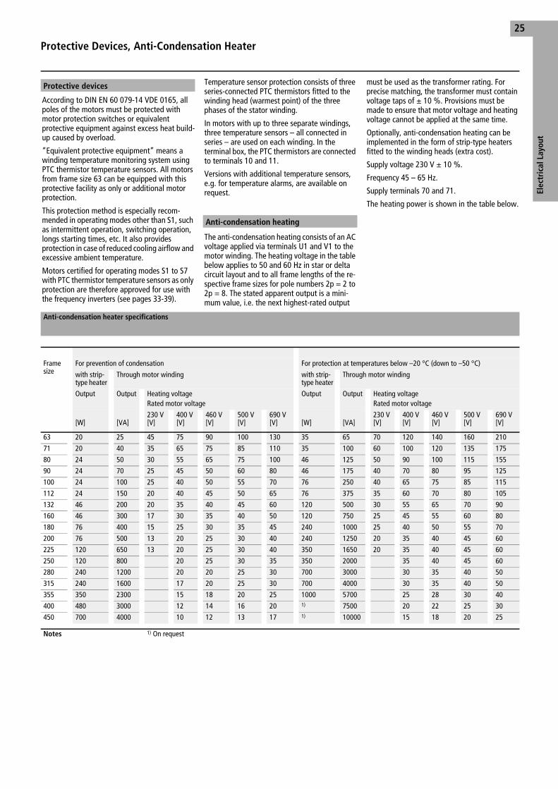
The anti-condensation heating consists of an AC voltage applied via terminals U1 and V1 to the motor winding. The heating voltage in the table below applies to 50 and 60 Hz in star or delta circuit layout and to all frame lengths of the re-spective frame sizes for pole numbers 2p = 2 to 2p = 8. The stated apparent output is a mini-mum value, i.e. the next highest-rated output
must be used as the transformer rating. For precise matching, the transformer must contain voltage taps of ± 10 %. Provisions must be made to ensure that motor voltage and heating voltage cannot be applied at the same time.
Optionally, anti-condensation heating can be implemented in the form of strip-type heaters fitted to the winding heads (extra cost).
Supply voltage 230 V ± 10 %.
Frequency 45 – 65 Hz.
Supply terminals 70 and 71.
The heating power is shown in the table below.
Protective devices
Anti-condensation heating
Anti-condensation heater specifications
Frame size
For prevention of condensation For protection at temperatures below –20 °C (down to –50 °C)
with strip-type heater
Through motor winding with strip-type heater
Through motor winding
Output Output Heating voltage Rated motor voltage
Output Output Heating voltage Rated motor voltage
[W] [VA]230 V[V]
400 V[V]
460 V[V]
500 V[V]
690 V[V] [W] [VA]
230 V[V]
400 V[V]
460 V[V]
500 V[V]
690 V[V]
63 20 25 45 75 90 100 130 35 65 70 120 140 160 210
71 20 40 35 65 75 85 110 35 100 60 100 120 135 175
80 24 50 30 55 65 75 100 46 125 50 90 100 115 155
90 24 70 25 45 50 60 80 46 175 40 70 80 95 125
100 24 100 25 40 50 55 70 76 250 40 65 75 85 115
112 24 150 20 40 45 50 65 76 375 35 60 70 80 105
132 46 200 20 35 40 45 60 120 500 30 55 65 70 90
160 46 300 17 30 35 40 50 120 750 25 45 55 60 80
180 76 400 15 25 30 35 45 240 1000 25 40 50 55 70
200 76 500 13 20 25 30 40 240 1250 20 35 40 45 60
225 120 650 13 20 25 30 40 350 1650 20 35 40 45 60
250 120 800 20 25 30 35 350 2000 35 40 45 60
280 240 1200 20 20 25 30 700 3000 30 35 40 50
315 240 1600 17 20 25 30 700 4000 30 35 40 50
355 350 2300 15 18 20 25 1000 5700 25 28 30 40
400 480 3000 12 14 16 20 1) 7500 20 22 25 30
450 700 4000 10 12 13 17 1) 10000 15 18 20 25
Notes 1) On request
Ff01e01g.fm Seite 25 Montag, 17. September 2001 9:46 09

Operating CharacteristicsFor Motors up to 690 V
Ope
rati
ng C
hara
cter
isti
cs26
Normally motors are supplied for the rated voltages listed on page 23 and for rated frequency of 50 Hz or 60 Hz. The rated output values are listed in the technical data tables.
The motors can be operated at their rated output in three-phase systems whose voltage deviates by ± 10 % from the rated voltage of the motor during operation, in accordance with IEC 38 and VDE 0530.
The efficiency values and power factors listed in the tables apply to operation at rated output, rated voltage and rated frequency. The efficiency values have been determined in accordance with VDE 0530 Part 2, Section 9 (lost-summation method), and the tolerances in accordance with VDE 0530 Part 1, table 8.
The output values in the tables apply at rated voltage and rated speed in continuous operation S1, a coolant temperature up to 40 °C and an altitude of up to 1000 m above m.s.l.
For higher ambient temperatures and altitudes above 1000 metres, output reductions become necessary. These are listed in the tables below:
The starting current values given as multiples of rated current in the operating data were ob-tained from a type test sample. The relationship between apparent starting power and the motor’s rated output is derived from the starting current relationship according to the following equation:
The motors have squirrel-cage rotors. On frame sizes 63 to 315, the cages are die-cast aluminium constructions with 2 to 8 poles; on larger sizes, they are hard-soldered copper deep bar constructions for direct actuation. The starting and stalling torques, expressed as multiples of the rated torques, are listed in the technical data tables. The figures are type sample readings.
If the voltage deviates from the rated value, the torques (starting torque, acceleration torque and stalling torque) change approximately as a square function of voltage.
In general, the motors can rotate in both directions. Only motors with self-driven axial-flow fans are unidirectional, the direction of rotation being indicated by an arrow on the fan cowl. Certified circuit diagrams are supplied with the motors.
If, for installation above 1000 m above m.s.l., the coolant temperature is reduced to the values shown in the table below (from VDE 0530 Part 1 Section 16.3.5 table 4), no power reduction is necessary.
Additional testing is required (incurring testing costs) for motors with a coolant temperature deviating from 40 °C, at an installation altitude other than 1000 m above sea level and whose outputs differ from the standard version.
Special acceptance tests are also required for operating modes other than S1 according to VDE 0530 Part 1. When making an inquiry, please provide the relevant information as required by paragraphs 4 and 11 of these regulations.
A winding temperature monitoring system ensures optimum utilization of the motor as well as overload protection (see page 25).
The motors can be overloaded in accordance with the requirements of VDE 0530. At operating temperature, they can run for two minutes at 1.5 times their rated current without incurring damage and can take 1.6 times their rated torque for 15 seconds.
The overcurrent relays that must be fitted according to the code of practice for electrical apparatus in hazardous areas allow only limited acceleration times. The resulting limited mass inertia moments are listed in the table on page 27. This means that up to two consecutive startups are possible up to frame size 315 and one startup from frame size 355.
Motors with PTC thermistor winding temperature monitoring can reach the starting times listed on page 27.
Voltage, frequency
Efficiency, power factor
Output, operating mode
Coolant temperature[°C]
Reduction of rated output to about
40 100 % see“Operating data”45 95 %
50 90 %55 85 %60 80 %
Height above m.s.l. [m]
Reduction of rated output to about
1000 100 % see“Operating data”1500 97 %
2000 94 %
Starting current, Apparent starting output
SA
P2----- IA/IN 1
η ϕcos×---------------------=
Torque
Direction of rotation
Height above m.s.l. [m]
Max. coolant temperature [°C]
0 to 1000 401000 1500 351500 2000 30
Overload, startup
Ff01e02g.fm Seite 26 Montag, 17. September 2001 9:46 09

Ope
rati
ng C
hara
cter
isti
cs
Permissible Startup Times for Air-Cooled Motors Without BrakeTemperature Class T4 – Protection By PTC Thermistor Sensors
27
lPermissible startup times
2p = 2 2p = 4 2p = 6 2p = 8Rated output Permissible starting time1) Permissible starting time1) Permissible starting time1) Permissible starting time1)
Cold Warm Cold Warm Cold Warm Cold WarmP2[kW]
t[s]
t[s]
t[s]
t[s]
t[s]
t[s]
t[s]
t[s]
0.12 – – 90 62 – – 100 59
0.18 60 40 90 62 – – 100 59
0.25 60 40 90 62 80 63 100 59
0.37 60 40 90 62 79 62 100 59
0.55 60 40 90 62 55 40 100 59
0.75 50 36 75 50 85 55 95 56
1.1 47 31 60 38 80 50 108 69
1.5 45 27 46 26 73 42 108 81
2.2 45 20 46 25 65 46 104 72
3.0 42 20 46 22 51 39 80 50
4.0 35 19 39 23 46 34 85 55
5.5 30 19 43 25 45 29 84 54
7.5 35 19 42 22 35 22 87 58
11 35 19 39 23 38 19 81 45
15 41 21 46 24 43 22 59 41
18.5 39 20 46 23 46 27 46 29
22 39 20 52 24 43 21 59 40
30 39 20 52 25 60 31 57 33
37 53 21 56 28 57 28 66 45
45 69 32 62 26 75 45 74 44
55 74 29 45 25 80 56 77 48
75 85 39 56 23 64 36 61 40
90 84 42 59 25 49 22 60 30
110 97 45 62 23 60 30 60 30
132 103 48 63 26 60 30 60 30
160 100 50 60 30 60 30 60 30
200 100 50 60 30 60 30 60 30
250 100 50 60 30 60 30 60 30
315 100 50 60 30 60 30 60 30
355 100 50 60 30 60 30 60 30
400 100 50 60 30 60 30 60 30
450 – – 60 30 60 30 – –
Notes 1) These times can be achieved only with winding temperature monitoring using PTC thermistor temperature sensors.
Ff01e02g.fm Seite 27 Donnerstag, 20. September 2001 11:42 11

Permissible Startups Per Hour for Air-Cooled Motors without BrakeTemperature Class T4
Ope
rati
ng C
hara
cter
isti
cs28
The number of permissible starts for the standard motor versions (temperature class T4), at thermal class F and with PC thermistor winding temperature monitoring are shown in the table on the right.
A distinction is made between:
1. Number of starts against constant load torque.
2. Number of starts against load torque rising to rated torque as a square of the speed.
The values given apply to inertia factor Fl = 1, i.e. they do not take the external moment of inertia into account. External moments of inertia can be included using the Fl factor according to the equation
The operating frequencies listed for motors under load are only accelerations, in contrast to the no-load operating frequencies. If the motors are decelerated with reverse current, these values must be divided by the K factor.
This K-factor is:K = 2.5 for constant load torqueK = 3.2 for quadratic rising load torque
The resulting relationship is:
[S/h] Operations per hour
Operating frequency
SSListe
Fl------------ [S/h]=
mit FlJZus. J+ Mot.
JMot.--------------------------=
Starts per hour
2p = 2 2p = 4 2p = 6 2p = 8Rated output Starts per hour,
FI = 1 Load torque
Starts per hour, FI = 1 Load torque
Starts per hour, FI = 1 Load torque
Starts per hour, FI = 1 Load torque
P2[kW]
const.[S/h]
squared[S/h]
const.[S/h]
squared[S/h]
const.[S/h]
squared[S/h]
const.[S/h]
squared[S/h]
0.12 11000 12000 6000 10200
0.18 8000 11000 11000 12000 6000 10200
0.25 8000 11000 11000 12000 10800 11450 6000 10200
0.37 8000 11000 11000 12000 10800 11450 5000 8500
0.55 8000 11000 10800 11550 10800 11450 5000 8500
0.75 7850 10500 10800 11550 6300 10590 4000 6800
1.1 5700 7560 6200 9550 5900 8880 6100 9900
1.5 3260 4410 3420 6480 2950 4580 9200 10500
2.2 1410 1960 2960 4400 2800 4100 4500 6930
3.0 980 1260 1930 2690 2600 3780 3900 5500
4.0 820 1200 2600 3490 2400 3460 2750 4530
5.5 610 880 1520 2050 2300 3150 2420 3480
7.5 780 1040 1000 1360 1340 1800 2190 3180
11 300 400 990 1360 720 1000 1100 1640
15 240 320 510 750 630 860 1330 1850
18.5 180 240 460 620 540 820 770 1040
22 130 170 130 180 400 540 1080 1430
30 65 100 300 400 290 380 410 560
37 55 75 230 310 170 240 370 560
45 50 65 110 170 200 280 205 305
55 40 55 95 130 220 310 270 305
75 30 45 70 100 100 170 220 330
90 25 35 40 65 90 150 120 180
110 18 27 23 30 80 125 170 230
132 16 25 30 55 70 100 150 190
160 12 22 30 45 55 85 150 190
200 8 20 22 35 50 75 150 190
250 8 18 18 30 40 60
315 8 18 18 30
Notes Frame sizes 355 to 450 available on requestOperating duty is possible only with winding temperature monitoringusing PTC thermistor temperature sensors.
SSListe[S/h]
Fl K×---------------------=
Ff01e02g.fm Seite 28 Montag, 17. September 2001 9:46 09
Ope
rati
ng C
hara
cter
isti
cs
Frequency Inverter Operation
29
If the frequency continues to increase beyond the drive’s rated value, the speed increases accordingly.
The speeds corresponding with the maximum frequencies must not exceed the motor’s speed limit. If a motor is operated above its rated frequency, its noise generation will increase.
To prevent excessive noise generation, the use of a motor with a separately driven external fan is recommended.
Two basic operating methods can be used for operation above the rated frequency (50 Hz):
If the motor is operated above its rated frequency at a voltage that increases in linear proportion with frequency, the magnetic flux remains constant.
Because the iron losses increase out of proportion to the frequency, the maximum torque is lower than it is at 50 Hz (figure 1, page 30).
The technical data tables list the output at 87 Hz or at the maximum frequency for 2-pole motors.
If voltage increase with frequency is linear, make sure that the voltage limits are not exceeded (see maximum permissible voltage load).
If the motor is operated above mains frequency at a constant voltage, the magnetic field is weakened.
The motor’s flux drops in inverse proportion to the frequency. In the range above the rated frequency (50 Hz to 87 Hz), the motor’s output remains approximately constant, i.e. the torque drops in inverse proportion to the frequency (figure 2, page 30).
The maximum frequency for two-pole motors is listed in the technical data tables.
Due to the harmonic oscillations, noise levels are higher in frequency inverter operation than they are at mains frequency. Without the use of a sinusoidal phase filter, the increase on the U-type inverter is about 7 – 15 dB(A); on the I-type inverter, it is about 3 dB(A).
If a filter is used with the U-type inverter, the noise levels at frequencies at or below 50 Hz do not exceed the values at mains operation.
The noise increase from self-ventilated motors at frequencies above 50 Hz is:
Guideline values for noise level increase due to increased fan noise.
Special motors are available for low-noise drives with inverter. These are listed on page 19.
Motors with separately driven external fans are recommended for drives with larger control ranges and constant load torque. These motors are also well-suited to operation above 50 Hz due to their low increase in noise generation at this frequency range.
The fan motor is housed in a flameproof enclosure.
The motor’s electrical control system must ensure that the main motor can only operate while the external fan is running.
If the current-limited inverter power output is not isolated from the mains, one of the following measures must be implemented to protect the earth conductor from overload as specified in DIN EN 50178, VDE 0160 (equipment of heavy-current installations with electrical apparatus).
The dimensioning of the protective device in the main poles must take into account that, in the event of a fault, the PE conductor current can be greater than the main pole current. The protective conductor must therefore be dimensioned for the fault current accordingly.
All the specifications of the inverter manu-facturer with regard to this fault must be observed.
Frequencies above the rated frequency 50 Hz
Three-phase motors, operated with a frequency inverter at constant flux up to 87 Hz
Three-phase motors, operated with a frequency inverter at constant voltage above 50 Hz
f [Hz]
D LP[dB(A)]
50 060
F 570
F 980
F 1287
F 15
Noise generation of three-phase motorsin frequency inverter operation
Motors with separately driven external fans
Installation note
Ff01e02g.fm Seite 29 Montag, 17. September 2001 9:46 09
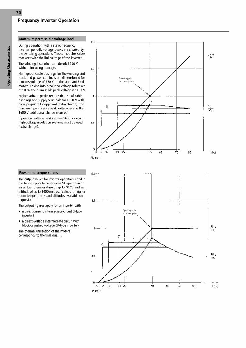
Frequency Inverter Operation
Ope
rati
ng C
hara
cter
isti
cs30
During operation with a static frequency inverter, periodic voltage peaks are created by the switching operations. This can require values that are twice the link voltage of the inverter.
The winding insulation can absorb 1600 V without incurring damage.
Flameproof cable bushings for the winding end leads and power terminals are dimensioned for a mains voltage of 750 V on the standard Ex d motors. Taking into account a voltage tolerance of 10 %, the permissible peak voltage is 1160 V.
Higher voltage peaks require the use of cable bushings and supply terminals for 1000 V with an appropriate Ex approval (extra charge). The maximum permissible peak voltage level is then 1600 V (additional charge incurred).
If periodic voltage peaks above 1600 V occur, high-voltage insulation systems must be used (extra charge).
Figure 1
The output values for inverter operation listed in the tables apply to continuous S1 operation at an ambient temperature of up to 40 °C and an altitude of up to 1000 metres. (Values for higher room temperatures and altitudes available on request.)
The output figures apply for an inverter with
• a direct-current intermediate circuit (I-type inverter)
• a direct-voltage intermediate circuit with block or pulsed voltage (U-type inverter)
The thermal utilization of the motors corresponds to thermal class F.
Figure 2
Maximum permissible voltage load
Operating pointon power system
Power and torque values
Operating pointon power system
Ff01e02g.fm Seite 30 Montag, 17. September 2001 9:46 09

Notes
31
Ff01e02g.fm Seite 31 Montag, 17. September 2001 9:46 09

Ope
rati
ng C
hara
cter
isti
cs32
Type3) Out-put
Rated current at
Speed Efficiency Power factor
Torque Start-ing torque
Start-ing cur-rent
Stall-ing torque
Mass inertia moment
Weight2) Noise values with radial-flow fan
Noise values with axial-flow fan Type ...A
KD1P2[kW]
400 V
I
[A]
500 V
I
[A]n [rpm]
η[%]
Classeff cos ϕ M[Nm]
MA/
MN
IA/
IN
MK/
MN J[kgm2]
m[kg]
Lp[dB(A)]
Lw[dB(A)]
Lp[dB(A)]
Lw[dB(A)]
067N-AA4.. 0.18 0.58 0.46 2905 66 0.68 0.59 4.6 6.8 6.5 0.00028 16 49 61
063N-AA4.. 0.25 0.67 0.54 2860 70 0.77 0.83 3.4 5.8 4.7 0.00028 16 49 61
077N-AA4.. 0.37 0.89 0.71 2800 71.5 0.84 1.26 2.7 5.2 3.5 0.00028 16 51 63
071N-AA4.. 0.55 1.29 1.04 2810 73 0.84 1.87 2.8 5.5 3.6 0.00039 17 51 63
087N-AA4.. 0.75 1.74 1.39 2790 74 0.84 2.57 2.7 4.8 3.3 0.00058 24 55 67
080N-AA4.. 1.1 2.4 1.92 2820 78 2 0.85 3.73 2.8 5.5 3.5 0.0008 25 55 67
097L-AA4.. 1.5 3.2 2.55 2840 79 2 0.86 5 2.7 5.5 3.2 0.0013 31 60 72
090L-AA4.. 2.2 4.5 3.6 2850 82 2 0.86 7.4 2.7 5.6 3.3 0.0018 35 60 72
100L-AA4.. 3 6.0 4.8 2850 83 2 0.87 10.1 2.7 6.8 3.3 0.0029 45 63 75
112M-AA4.. 4 7.7 6.2 2880 85 2 0.88 13.3 2.3 6.5 3.1 0.0051 53 63 75
137S-AA4.. 5.5 10.7 8.6 2880 85 3 0.87 18.2 2.5 6 3.3 0.0089 95 63 76 55 68
132S-AA4.. 7.5 14.4 11.5 2910 86.5 3 0.87 24.6 2.7 6.8 3.5 0.0125 100 63 76 55 68
167M-AA4.. 11 20 16.1 2925 88.5 2 0.89 36 2.8 6.6 3.2 0.032 163 66 79 56 69
160M-AA4.. 15 26.5 21 2920 89.5 2 0.92 49 2.8 6.8 3.2 0.043 173 66 79 56 69
160L-AA4.. 18.5 32 25.5 2925 91 2 0.92 60 2.6 6.8 3.1 0.052 188 66 79 56 69
180M-AA4.. 22 37.5 30 2925 91.7 2 0.92 72 2.5 6.9 3 0.075 196 69 82 58 71
207L-AA4.. 30 52 41.5 2955 92.5 2 0.9 97 2.6 7.2 2.9 0.13 254 71 85 60 74
200L-AA4.. 37 64 51 2955 93 2 0.9 120 2.7 7.2 3 0.16 278 71 85 60 74
225M-AA4.. 45 78 63 2960 93 2 0.89 145 2.5 7.1 3 0.24 400 72 86 60 74
250M-AA4.. 55 95 76 2970 93.8 2 0.89 177 2.4 7.1 2.8 0.4 545 75 89 64 78
280S-AA4.. 75 127 102 2970 94.5 2 0.9 241 2.2 6.8 2.7 0.65 700 76 90 66 80
280M-AA4.. 90 153 122 2970 94.5 2 0.9 289 2.4 6.6 2.8 0.78 762 76 90 66 80
315S-AA4.. 110 186 149 2975 95 0.9 353 2 6.3 2.4 1.4 960 79 94 66 81
315M-AA4.. 132 220 177 2975 95.5 0.9 424 2.1 6.8 2.5 1.6 1025 79 94 66 81
317L-AA4.. 160 270 215 2975 95.7 0.9 514 2.4 6.9 2.7 1.7 1065 79 94 66 81
315L-AA4.. 200 335 270 2980 95.8 0.9 641 2.3 6.9 2.6 2.2 1270 79 94 66 81
318L-AA4.. 250 4151) 330 2980 96.0 0.91 801 1.7 7.2 2.7 2.8 1420 79 94 66 81
357L-AA4.. 315 5101) 4101) 2980 96.6 0.92 1009 1.5 6.7 2.8 4.5 1900 81 97 68 84
355L-AA4.. 355 5701) 4551) 2985 96.8 0.93 1136 1.4 6.9 2.7 5 2050 81 97 68 84
400M-AA4.. 400 6351) 5051) 2990 96.9 0.94 1278 1.1 6.7 2.8 7.5 2500 81 97
Notes 1) Two parallel supply lines are required for each phase 2) Construction type B3 with terminal box3) For order the type of construction and the nominal voltage are to be given in clear.
Mains Operation; Operating Data, 50 HzTemperature Class T4, ns = 3000 rpm, 2p = 2
Ff01e02g.fm Seite 32 Montag, 17. September 2001 9:46 09

Ope
rati
ng C
hara
cter
isti
cs
33
Operation on the Mains Inverter
Ventilation Self-ventilation Separate
Torque character. – drop by square val. constant constant constant constant constantFrequency 50 Hz 5 – 50 Hz 20 – 50 Hz 10 – 50 Hz 5 – 50 Hz 50 – 87 Hz1) 5 – 87 Hz1)
Control range – 1:10 5 1:2.5 1:5 1:10Speed range – 300 – 3000 rpm 1200 – 3000 rpm 600 – 3000 rpm 300 – 3000 rpm 3000 – 5220 rpm 300 – 5220 rpmOutput/mom. P2[kW] Pu[kW] Mu[Nm] Pu[kW] Mu[Nm] Pu[kW] Mu[Nm] Pu[kW] Mu[Nm] Pu[kW] Mu[Nm] Pu[kW] Pu[kW]
50 Hz 50 Hz 50 Hz 50 Hz 87 Hz 50 Hz 87 Hz
KD1 067N-AA4.. 0.18 0.18 0.61 0.18 0.61 0.17 0.57 0.16 0.54 0.23 0.42 – –
KD1 063N-AA4.. 0.25 0.25 0.86 0.25 0.86 0.23 0.78 0.22 0.74 0.32 0.6 – –
KD1 077N-AA4.. 0.37 0.37 1.25 0.35 1.2 0.3 1 0.22 0.74 0.55 1 – –
KD1 071N-AA4.. 0.55 0.55 1.9 0.52 1.8 0.45 1.5 0.33 1.1 0.8 1.5 – –
KD1 087N-AA4.. 0.75 0.75 2.6 0.7 2.4 0.6 2 0.5 1.7 1.1 2 – –
KD1 080N-AA4.. 1.1 1.1 3.7 1 3.4 0.9 3 0.75 2.5 1.6 2.9 – –
KD1 097L-AA4.. 1.5 1.5 5 1.4 4.7 1.2 4 1 3.3 2.2 4 – –
KD1 090L-AA4.. 2.2 2.2 7.4 2 6.7 1.7 5.7 1.4 4.7 3.3 6 – –
KD1 100L-AA4.. 3 3 10 2.7 8.9 2.2 7.2 1.8 5.9 4.5 8.2 – –
KD1 112M-AA4.. 4 4 13 3.7 12 3.2 11 2.5 8.2 6 11 – –
KD1 137S-AA4.. 5.5 5.5 18 5 16 4.5 15 3.7 12 8 15 5.5 8
KD1 132S-AA4.. 7.5 7.5 25 7 23 6 20 5 16 11 20 7.5 10.5
KD1 167M-AA4.. 11 11 36 10 32 9 29 7.5 24 16 29 11 15
KD1 160M-AA4.. 15 14.52) 47 13 42 12 39 10 32 21 38 14.5 20
KD1 160L-AA4.. 18.5 17.52) 57 16 52 15 49 12.5 41 26 48 17.5 25
KD1 180M-AA4.. 22 212) 68 20 65 18 58 15 49 30 55 21 29
KD1 207L-AA4.. 30 282) 90 27 87 24 77 22 71 40 73 28 38
KD1 200L-AA4.. 37 322) 103 31 100 28 90 27 87 49 90 32 45
KD1 225M-AA4.. 45 382) 123 37 119 34 110 32 103 60 110 38 55
Frequency 50 – 60 Hz1) 5 – 60 Hz1)
Speed range 3000 – 600 rpm 300 – 3600 rpm
KD1 250M-AA4.. 55 472) 151 45 145 43 138 41 132 55 146 47 55
KD1 280S-AA4.. 75 622) 199 60 193 58 186 55 177 75 200 62 75
KD1 280M-AA4.. 90 752) 241 73 234 70 225 67 215 90 240 75 90
KD1 315S-AA4.. 110 952) 304 90 288 88 282 85 272 115 305 95 115
KD1 315M-AA4.. 132 115 369 110 353 105 336 100 320 135 358 115 135
KD1 317L-AA4.. 160 140 449 135 433 128 410 120 385 165 438 140 165
KD1 315L-AA4.. 200 175 560 165 528 160 512 150 480 210 557 175 210
KD1 318L-AA4.. 250 215 688 205 656 200 640 185 592 260 690 215 260
KD1 357L-AA4.. 315 270 865 260 832 250 800 235 752 325 862 270 325
KD1 355L-AA4.. 355 305 976 295 944 285 912 265 848 365 968 305 365
KD1 400M-AA4.. 400 345 1104 335 1072 320 1024 300 960 415 1100 345 415
Notes 1) Higher frequencies available on request 2) For inverter operation with output filter and virtually sinusoidal output voltage, output as for P2
Output for operation with inverter (reference values)Overload protection through temperature sensors
Inverter Operation; Operating Data, 50 HzTemperature Class T4 ns = 3000 rpm, 2p = 2
Ff01e02g.fm Seite 33 Montag, 17. September 2001 9:46 09

Ope
rati
ng C
hara
cter
isti
cs34
Type3) Out-put
Rated current at
Speed Efficiency Power factor
Torque
Start-ing torque
Start-ing cur-rent
Stall-ing torque
Mass inertia moment
Weight2) Noise values with radial-flow fan
Noise values with axial-flow fan Type ...A
KD1P2 [kW]
400 V
I
[A]
500 V
I
[A]n[rpm]
η[%]
Classeff cos ϕ M[Nm]
MA/
MN
IA/
IN
MK/
MN J[kgm2]
m[kg]
Lp[dB(A)]
Lw[dB(A)]
Lp[dB(A)]
Lw[dB(A)]
067N-BA4.. 0.12 0.43 0.34 1445 67 0.6 0.79 3.9 5.6 3.9 0.00046 16 44 56
063N-BA4.. 0.18 0.53 0.42 1415 70 0.7 1.2 2.7 4.7 2.7 0.00046 16 44 56
077N-BA4.. 0.25 0.68 0.55 1370 66 0.8 1.74 2 3.9 2.5 0.00046 16 45 57
071N-BA4.. 0.37 0.95 0.76 1380 70 0.8 2.56 2.2 3.9 2.6 0.00063 17 45 57
087N-BA4.. 0.55 1.36 1.09 1380 73 0.8 3.8 2 3.8 2.3 0.00092 24 46 58
080N-BA4.. 0.75 1.83 1.46 1400 75 0.79 5.1 2.1 4.2 2.5 0.0013 25 46 58
097L-BA4.. 1.1 2.5 2.0 1400 76 2 0.84 7.5 2.1 4.8 2.5 0.0021 31 49 61
090L-BA4.. 1.5 3.3 2.65 1405 79 2 0.83 10.2 2.3 5 2.7 0.0029 35 49 61
107L-BA4.. 2.2 4.95 3.95 1420 80 3 0.8 14.8 2.4 5.4 2.8 0.0046 44 52 64
100L-BA4.. 3 6.6 5.2 1415 80.5 3 0.82 20.2 2.3 5.5 2.7 0.0056 46 52 64
112M-BA4.. 4 8.1 6.5 1435 85 2 0.84 26.6 2.7 6.8 3.2 0.011 59 54 66
132S-BA4.. 5.5 10.7 8.5 1440 86.5 2 0.86 36.5 2.5 6.2 2.7 0.022 100 57 70
132M-BA4.. 7.5 14.3 11.4 1440 88 2 0.86 50 2.7 6.5 2.8 0.03 110 57 70
160M-BA4.. 11 21 16.7 1460 89.5 2 0.85 72 2.5 6.6 2.8 0.057 168 62 75
160L-BA4.. 15 28 22.5 1455 90 2 0.86 98 2.8 6.5 3.1 0.079 184 62 75
180M-BA4.. 18.5 35 28 1460 91 2 0.84 121 2.9 6.6 3 0.13 198 60 73 57 70
180L-BA4.. 22 41 32.5 1460 91.5 2 0.85 144 3 6.9 3 0.155 217 60 75 57 70
200L-BA4.. 30 53 42.5 1460 92.5 2 0.88 196 2.6 6.8 2.9 0.25 274 61 75 58 72
225S-BA4.. 37 65 52 1465 93 2 0.89 241 2.7 6.7 2.6 0.4 372 63 77 59 73
225M-BA4.. 45 78 63 1470 93 2 0.89 292 2.7 6.5 2.6 0.48 402 63 77 59 73
250M-BA4.. 55 95 76 1470 93.8 2 0.89 357 2.9 7.1 2.9 0.75 573 65 79 64 78
280S-BA4.. 75 133 107 1480 94.5 2 0.86 484 2.6 6.8 2.5 1.25 740 68 82 66 80
280M-BA4.. 90 160 128 1480 94.5 2 0.86 581 2.8 6.9 2.6 1.48 820 68 82 66 80
315S-BA4.. 110 194 155 1485 95.1 0.86 707 2.5 6.7 2.6 2.2 1040 70 85 66 81
315M-BA4.. 132 230 186 1485 95.3 0.86 849 2.5 6.8 2.7 2.7 1120 70 85 66 81
317L-BA4.. 160 280 220 1485 95.6 0.87 1029 2.6 6.9 2.6 3.1 1210 70 85 66 81
315L-BA4.. 200 345 275 1485 95.8 0.87 1286 2.6 6.9 2.6 3.9 1430 70 85 66 81
318L-BA4.. 250 4201) 340 1490 96.2 0.89 1602 1.7 7.3 2.7 4.6 1565 70 85 66 81
357L-BA4.. 315 5301) 4251) 1490 96.3 0.89 2019 1.5 6.9 2.7 6.1 2050 72 88 68 84
355L-BA4.. 355 5951) 4751) 1490 96.6 0.89 2275 1.6 6.9 2.8 6.7 2200 72 88 68 84
400S-BA4.. 400 6601) 5301) 1495 97 0.9 2555 1.3 6.7 2.8 16 2650 78 94
400M-BA4.. 450 7351) 5901) 1495 97 0.91 2875 1.1 6.5 2.7 18 2850 78 94
450S-BA4.. 500 8151) 6551) 1495 97.2 0.91 3194 1 6.9 2.7 23 3300 79 95
450M-BA4.. 560 7301) 1495 97.4 0.91 3577 1 6.8 2.7 26 3500 79 95
450L-BA4.. 630 8201) 1495 97.4 0.91 4024 1 6.8 2.7 31 3800 79 95
500 On request
Notes 1) Two parallel supply lines are required for each phase2) Construction type B3 with terminal box3) For order the type of construction and the nominal voltage are to be given in clear.
Mains Operation; Operating Data, 50 Hz Temperature Class T4 ns = 1500 rpm, 2p = 4
Ff01e02g.fm Seite 34 Montag, 17. September 2001 9:46 09

Ope
rati
ng C
hara
cter
isti
cs
35
Operation on the Mains Inverter
Ventilation Self-ventilation Separate
Torque character. – drop by square val. constant constant constant constant constantFrequency 50 Hz 5 – 50 Hz 20 – 50 Hz 10 – 50 Hz 5 – 50 Hz 50 – 87 Hz1) 5 – 87 Hz1)
Control range – 1:10 1:2.5 1:5 1:10Speed range – 150 – 1500 rpm 600 – 1500 rpm 300 – 1500 rpm 150 – 1500 rpm 1500 – 2610 rpm 150 – 2610 rpmOutput/mom. P2[kW] Pu[kW] Mu[Nm] Pu[kW] Mu[Nm] Pu[kW] Mu[Nm] Pu[kW] Mu[Nm] Pu[kW] Mu[Nm] Pu[kW] Pu[kW]
50 Hz 50 Hz 50 Hz 50 Hz 87 Hz 50 Hz 87 Hz
KD1 067N-BA4.. 0.12 0.12 0.83 0.12 0.83 0.11 0.75 0.11 0.75 0.16 0.59 – –
KD1 063N-BA4.. 0.18 0.18 1.25 0.18 1.25 0.17 1.18 0.16 1.1 0.23 0.84 – –
KD1 077N-BA4.. 0.25 0.25 1.7 0.22 1.5 0.19 1.25 0.15 1 0.37 1.4 – –
KD1 071N-BA4.. 0.37 0.37 2.5 0.33 2.2 0.28 1.9 0.22 1.5 0.55 2 – –
KD1 087N-BA4.. 0.55 0.55 3.8 0.52 3.5 0.45 3 0.33 2.2 0.8 2.9 – –
KD1 080N-BA4.. 0.75 0.75 5.2 0.7 4.8 0.6 4 0.5 3.3 1.1 4 – –
KD1 097L-BA4.. 1.1 1.1 7.5 1 6.7 0.9 6 0.75 5 1.6 5.9 – –
KD1 090L-BA4.. 1.5 1.5 10 1.4 9.5 1.2 8 1 6.7 2.2 8 – –
KD1 107L-BA4.. 2.2 2.2 15 2 13 1.7 11 1.4 9.3 3.3 12 – –
KD1 100L-BA4.. 31) 3 20 2.8 19 2.2 15 1.8 12 4.5 16 – –
KD1 112M-BA4.. 4 4 27 3.6 24 3 20 2.5 16 6 22 – –
KD1 132S-BA4.. 5.5 5.5 37 5 33 4.4 29 3.7 24 8 29 5.5 8
KD1 132M-BA4.. 7.5 7.5 50 7 46 6 39 5 33 11 40 7.5 10.5
KD1 160M-BA4.. 11 11 72 10 65 9 58 7.5 49 16 59 11 15
KD1 160L-BA4.. 15 15 98 13.5 88 12 78 10 65 21 79 15 20
KD1 180M-BA4.. 18.5 182) 118 17 111 15 97 12.5 81 26 95 18 25
KD1 180L-BA4.. 22 212) 137 20 130 18 117 15 97 30 110 21 29
KD1 200L-BA4.. 30 282) 183 27 176 24 156 21 136 40 146 28 37
KD1 225S-BA4.. 37 322) 208 31 201 29 188 26 168 49 179 32 45
KD1 225M-BA4.. 45 382) 247 37 240 35 227 32 207 60 220 38 55
KD1 250M-BA4.. 55 462) 298 45 291 43 278 41 265 70 256 46 65
KD1 280S-BA4.. 75 622) 400 60 386 58 373 55 354 95 348 62 88
KD1 280M-BA4.. 90 752) 482 73 470 70 450 66 424 110 402 75 105
KD1 315S-BA4.. 110 952) 610 90 577 88 564 83 532 140 512 95 130
KD1 315M-BA4.. 132 115 737 110 705 105 673 100 641 165 604 115 157
KD1 317L-BA4.. 160 140 897 135 865 128 820 120 769 200 732 140 190
KD1 315L-BA4.. 200 175 1122 165 1058 160 1026 150 961 250 915 175 240
KD1 318L-BA4.. 250 215 1378 205 1314 200 1282 185 1186 310 1134 215 305
KD1 357L-BA4.. 315 270 1731 260 1666 250 1602 235 1506 395 1445 270 385
KD1 355L-BA4.. 355 305 1955 295 1891 285 1827 265 1698 440 1610 305 425
KD1 400S-BA4.. 400 345 2211 335 2147 320 2051 300 1923 495 1811 345 480
KD1 400M-BA4.. 450 390 2500 375 2405 360 2307 340 2179 560 2050 390 540
Notes 1) Higher frequencies available on request 2) For inverter operation with output filter and virtually sinusoidal output voltage, output as for P2
Output for operation with inverter (reference values)Overload protection through temperature sensors
Inverter Operation; Operating Data, 50 Hz Temperature Class T4 ns = 1500 rpm, 2p = 4
Ff01e02g.fm Seite 35 Montag, 17. September 2001 9:46 09

Ope
rati
ng C
hara
cter
isti
cs36
Type3) Output Rated current at Speed Effi-ciency
Power factor
Torque Start-ing torque
Start-ing cur-rent
Stalling torque
Mass inertia moment
Weight2) Noise values with radial-flow fan
400 V 500 V
KD1P2 [kW]
I
[A]
I
[A]n[rpm]
η[%]
cos ϕ M[Nm]
MA/
MN
IA/
IN
MK/
MN J[kgm2]
m[kg]
Lp[dB(A)]
Lw[dB(A)]
071N-CA4.. 0.25 0.8 0.64 920 63.5 0.71 2.6 2.2 3.5 2.6 0.0012 17 44 56
087N-CA4.. 0.37 1.11 0.88 925 68 0.72 3.8 2.5 4.1 2.8 0.0019 24 44 56
080N-CA4.. 0.55 1.58 1.26 925 70 0.72 5.7 2.4 4 2.7 0.0025 25 44 56
097L-CA4.. 0.75 2.15 1.72 910 67 0.75 7.9 1.8 3.4 2.1 0.0033 31 47 59
090L-CA4.. 1.1 3.05 2.45 920 71 0.73 11.4 2 3.7 2.2 0.0046 35 47 59
100L-CA4.. 1.5 3.75 3 945 77 0.75 15.2 2.5 4.9 3 0.0095 46 50 62
112M-CA4.. 2.2 5.2 4.2 950 81 0.75 22.1 2.7 5.6 3.1 0.017 59 53 65
132S-CA4.. 3 6.6 5.3 965 84 0.78 29.7 2.7 6.3 3.1 0.031 100 56 69
137M-CA4.. 4 8.6 6.9 960 84.5 0.79 40 2.6 6 3 0.037 104 56 69
132M-CA4.. 5.5 11.3 9.1 960 85.5 0.82 55 2.6 6.4 3 0.043 112 56 69
160M-CA4.. 7.5 14.7 11.8 960 86.5 0.85 75 2.5 6.8 3.3 0.087 170 58 71
160L-CA4.. 11 21.5 17.1 965 87.5 0.85 109 2.5 6.7 3.2 0.12 190 58 71
180L-CA4.. 15 28.5 23 965 90 0.84 148 2.4 6.9 3.2 0.19 215 58 71
207L-CA4.. 18.5 35.0 28 975 90.5 0.84 181 1.9 6.2 2.7 0.28 270 58 71
200L-CA4.. 22 41.5 33 970 91 0.84 217 2.2 6.8 3 0.31 280 58 72
225M-CA4.. 30 56 45 975 92 0.84 294 2.8 6.6 2.5 0.69 404 58 72
250M-CA4.. 37 68 54 980 92.5 0.85 361 2.8 6.6 2.6 1.03 570 62 76
280S-CA4.. 45 85 68 985 93.3 0.82 436 2.8 5.8 2.4 1.35 720 63 77
280M-CA4.. 55 104 83 985 93.5 0.82 533 2.7 5.8 2.3 1.7 770 65 79
315S-CA4.. 75 132 106 990 94 0.87 723 2.6 6.4 2.4 4.3 995 65 79
315M-CA4.. 90 157 125 990 94.2 0.88 868 2.6 6.5 2.4 5.0 1050 69 84
317L-CA4.. 110 191 153 990 94.5 0.88 1061 2.7 6.5 2.5 6.0 1145 69 84
315L-CA4.. 132 230 183 990 94.7 0.88 1273 2.7 6.7 2.5 7.3 1265 69 84
355S-CA4.. 160 275 220 990 95 0.88 1543 2.6 6.8 2.5 8.3 1440 69 84
355M-CA4.. 200 345 275 990 95.6 0.88 1929 1.8 6.7 2.7 11.3 1750 74 90
355L-CA4.. 250 4301) 345 990 95.9 0.88 2411 1.8 6.7 2.7 13.8 1950 74 90
400S-CA4.. 315 5301) 4251) 993 96.3 0.89 3029 1 6.5 2.6 23 2650 78 94
400M-CA4.. 355 5951) 4751) 994 96.6 0.89 3411 1.1 6.6 2.7 27 2850 78 94
450S-CA4.. 400 6651) 5301) 995 96.8 0.9 3839 1 6.9 2.6 41 3300 78 94
450M-CA4.. 450 7551) 6051) 995 96.6 0.89 4319 1.2 6.8 2.8 46 3600 78 94
450L-CA4.. 500 6701) 995 97 0.89 4799 1.1 6.8 2.7 51 3800 78 94
500... On request
Notes 1) Two parallel supply lines are required for each phase 2) Construction type B3 with terminal box3) For order the type of construction and the nominal voltage are to be given in clear.
Mains Operation; Operating Data, 50 Hz Temperature Class T4 ns = 1000 rpm, 2p = 6
Ff01e02g.fm Seite 36 Montag, 17. September 2001 9:46 09
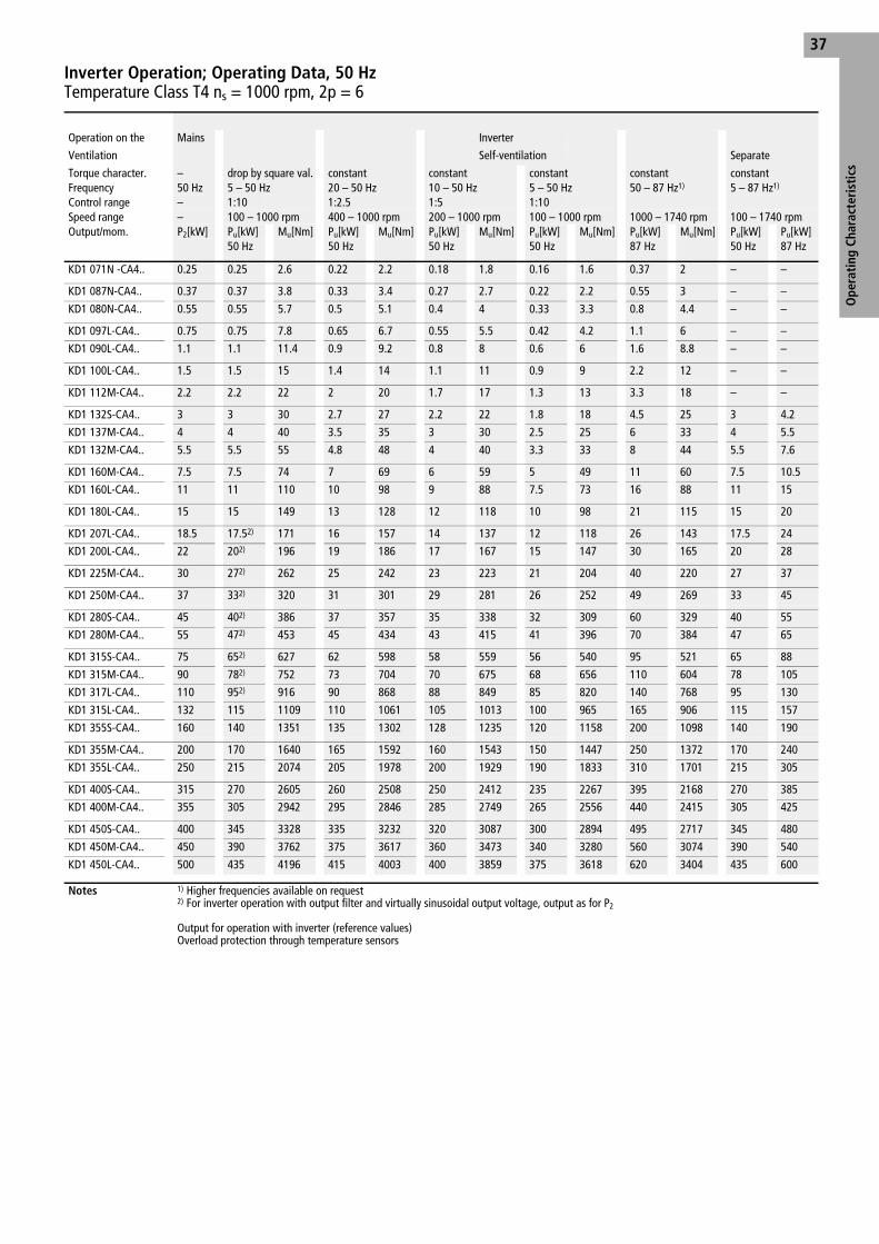
Ope
rati
ng C
hara
cter
isti
cs
37
Operation on the Mains Inverter
Ventilation Self-ventilation Separate
Torque character. – drop by square val. constant constant constant constant constantFrequency 50 Hz 5 – 50 Hz 20 – 50 Hz 10 – 50 Hz 5 – 50 Hz 50 – 87 Hz1) 5 – 87 Hz1)
Control range – 1:10 1:2.5 1:5 1:10Speed range – 100 – 1000 rpm 400 – 1000 rpm 200 – 1000 rpm 100 – 1000 rpm 1000 – 1740 rpm 100 – 1740 rpmOutput/mom. P2[kW] Pu[kW] Mu[Nm] Pu[kW] Mu[Nm] Pu[kW] Mu[Nm] Pu[kW] Mu[Nm] Pu[kW] Mu[Nm] Pu[kW] Pu[kW]
50 Hz 50 Hz 50 Hz 50 Hz 87 Hz 50 Hz 87 Hz
KD1 071N -CA4.. 0.25 0.25 2.6 0.22 2.2 0.18 1.8 0.16 1.6 0.37 2 – –
KD1 087N-CA4.. 0.37 0.37 3.8 0.33 3.4 0.27 2.7 0.22 2.2 0.55 3 – –
KD1 080N-CA4.. 0.55 0.55 5.7 0.5 5.1 0.4 4 0.33 3.3 0.8 4.4 – –
KD1 097L-CA4.. 0.75 0.75 7.8 0.65 6.7 0.55 5.5 0.42 4.2 1.1 6 – –
KD1 090L-CA4.. 1.1 1.1 11.4 0.9 9.2 0.8 8 0.6 6 1.6 8.8 – –
KD1 100L-CA4.. 1.5 1.5 15 1.4 14 1.1 11 0.9 9 2.2 12 – –
KD1 112M-CA4.. 2.2 2.2 22 2 20 1.7 17 1.3 13 3.3 18 – –
KD1 132S-CA4.. 3 3 30 2.7 27 2.2 22 1.8 18 4.5 25 3 4.2
KD1 137M-CA4.. 4 4 40 3.5 35 3 30 2.5 25 6 33 4 5.5
KD1 132M-CA4.. 5.5 5.5 55 4.8 48 4 40 3.3 33 8 44 5.5 7.6
KD1 160M-CA4.. 7.5 7.5 74 7 69 6 59 5 49 11 60 7.5 10.5
KD1 160L-CA4.. 11 11 110 10 98 9 88 7.5 73 16 88 11 15
KD1 180L-CA4.. 15 15 149 13 128 12 118 10 98 21 115 15 20
KD1 207L-CA4.. 18.5 17.52) 171 16 157 14 137 12 118 26 143 17.5 24
KD1 200L-CA4.. 22 202) 196 19 186 17 167 15 147 30 165 20 28
KD1 225M-CA4.. 30 272) 262 25 242 23 223 21 204 40 220 27 37
KD1 250M-CA4.. 37 332) 320 31 301 29 281 26 252 49 269 33 45
KD1 280S-CA4.. 45 402) 386 37 357 35 338 32 309 60 329 40 55
KD1 280M-CA4.. 55 472) 453 45 434 43 415 41 396 70 384 47 65
KD1 315S-CA4.. 75 652) 627 62 598 58 559 56 540 95 521 65 88
KD1 315M-CA4.. 90 782) 752 73 704 70 675 68 656 110 604 78 105
KD1 317L-CA4.. 110 952) 916 90 868 88 849 85 820 140 768 95 130
KD1 315L-CA4.. 132 115 1109 110 1061 105 1013 100 965 165 906 115 157
KD1 355S-CA4.. 160 140 1351 135 1302 128 1235 120 1158 200 1098 140 190
KD1 355M-CA4.. 200 170 1640 165 1592 160 1543 150 1447 250 1372 170 240
KD1 355L-CA4.. 250 215 2074 205 1978 200 1929 190 1833 310 1701 215 305
KD1 400S-CA4.. 315 270 2605 260 2508 250 2412 235 2267 395 2168 270 385
KD1 400M-CA4.. 355 305 2942 295 2846 285 2749 265 2556 440 2415 305 425
KD1 450S-CA4.. 400 345 3328 335 3232 320 3087 300 2894 495 2717 345 480
KD1 450M-CA4.. 450 390 3762 375 3617 360 3473 340 3280 560 3074 390 540
KD1 450L-CA4.. 500 435 4196 415 4003 400 3859 375 3618 620 3404 435 600
Notes 1) Higher frequencies available on request 2) For inverter operation with output filter and virtually sinusoidal output voltage, output as for P2
Output for operation with inverter (reference values)Overload protection through temperature sensors
Inverter Operation; Operating Data, 50 HzTemperature Class T4 ns = 1000 rpm, 2p = 6
Ff01e02g.fm Seite 37 Montag, 17. September 2001 9:46 09

Ope
rati
ng C
hara
cter
isti
cs38
Type3) Output Rated current at
Speed Effi-ciency
Power factor
Torque Starting torque
Starting current
Stalling torque
Mass inertia moment
Weight2) Noise values with radial-flow fan
KD1P2[kW]
400 V
I [A]
500 V
I
[A]n[rpm]
η[%]
cos ϕ M[Nm]
MA/
MN
IA/
IN
MK/
MN J[kgm2]
m[kg]
Lp[dB(A)]
Lw[dB(A)]
071N-DA4.. 0.12 0.50 0.40 680 52 0.67 1.7 1.9 2.4 2.4 0.0012 17 41 53
087N-DA4.. 0.18 0.66 0.52 690 61 0.65 2.5 2.2 3.2 2.6 0.0019 24 42 54
080N-DA4.. 0.25 0.91 0.73 690 62 0.64 3.5 2.2 3.2 2.5 0.0025 25 42 54
097L-DA4.. 0.37 1.32 1.06 690 64 0.63 5.1 1.8 3 2.2 0.0033 31 46 58
090L-DA4.. 0.55 1.88 1.50 690 65 0.65 7.6 1.8 3.1 2.2 0.0046 35 46 58
107L-DA4.. 0.75 2.3 1.82 710 71 0.67 10.1 2.4 4 2.6 0.008 44 49 61
100L-DA4.. 1.1 3.1 2.5 695 70 0.73 15.1 2 3.8 2.4 0.0095 46 49 61
112M-DA4.. 1.5 4.15 3.3 710 78 0.67 20.2 2.2 4.6 2.8 0.017 59 52 64
132S-DA4.. 2.2 4.95 3.95 695 81 0.79 30 2 4.1 2.3 0.029 97 53 66
132M-DA4.. 3 6.9 5.5 705 81.5 0.77 41 2.4 4.6 2.7 0.036 113 53 66
167M-DA4.. 4 8.8 7.0 715 84 0.78 53 1.8 4.6 2.3 0.071 157 54 67
160M-DA4.. 5.5 12.0 9.6 720 86 0.77 73 2.1 5.4 2.8 0.105 170 54 67
160L-DA4.. 7.5 16.3 13 720 86.5 0.77 99 2.2 5.6 2.9 0.136 190 54 67
180L-DA4.. 11 22.5 17.9 725 88.5 0.80 145 2.4 6.4 3 0.22 215 56 69
200L-DA4.. 15 31.0 24.5 730 89 0.79 196 2.7 6.9 3.2 0.4 280 56 70
225S-DA4.. 18.5 37.5 30.0 730 90.2 0.79 242 2.2 6.3 3 0.56 372 57 71
225M-DA4.. 22 44.0 35.0 730 90.5 0.80 288 2.2 6.6 3 0.69 404 57 71
250M-DA4.. 30 59 47 735 92.1 0.80 390 2 6.8 3 1.2 550 58 72
280S-DA4.. 37 70 56 735 92.8 0.82 481 2.1 6.2 2.8 1.9 740 61 75
280M-DA4.. 45 84 67 735 92.8 0.82 585 2 6.3 2.6 2.3 800 61 75
315S-DA4.. 55 103 82 740 92.8 0.83 710 2.5 6 2.6 4.3 995 68 83
315M-DA4.. 75 140 112 740 93 0.83 968 2.5 6.3 2.5 5.0 1050 68 83
317L-DA4.. 90 170 136 740 93.2 0.82 1161 2.6 6.6 2.6 6.0 1145 68 83
315L-DA4.. 110 210 166 740 93.2 0.82 1420 2.7 6.8 2.7 7.3 1265 68 83
355S-DA4.. 132 250 199 735 93.4 0.82 1715 2.5 6.3 2.5 8.3 1440 68 83
355M-DA4.. 160 295 235 740 95.1 0.83 2065 1.9 6.4 2.4 11.4 1750 70 86
355L-DA4.. 200 365 290 745 95.5 0.83 2564 1.7 6.6 2.5 13.9 1950 70 86
400S-DA4.. 250 4551) 360 745 96 0.83 3205 1.2 6.1 2.4 23 2650 73 89
400M-DA4.. 315 5651) 4501) 745 96.2 0.84 4038 1.2 6.2 2.4 30 3100 73 89
450S-DA4.. 355 6301) 5051) 745 96.5 0.84 4551 1 6.1 2.3 46 3450 74 90
450M-DA4.. 400 7101) 5701) 745 96.6 0.84 5128 1 6.1 2.2 51 3750 74 90
450L-DA4.. 450 8001) 6401) 745 96.7 0.84 5768 1 6.1 2.2 57 4050 74 90
500... On request
Notes 1) Two parallel supply lines are required for each phase 2) Construction type B3 with terminal box3) For order the type of construction and the nominal voltage are to be given in clear.
Mains Operation; Operating Data, 50 HzTemperature Class T4 ns = 750 rpm, 2p = 8
Ff01e02g.fm Seite 38 Montag, 17. September 2001 9:46 09

Ope
rati
ng C
hara
cter
isti
cs
39
Operation on the Mains Inverter
Ventilation Self-ventilation Separate
Torque character. – drop by square val. constant constant constant constant constantFrequency 50 Hz 5 – 50 Hz 20 – 50 Hz 10 – 50 Hz 5 – 50 Hz 50 – 87 Hz1) 5 – 87 Hz1)
Control range – 1:10 1:2.5 1:5 1:10Speed range – 75 – 7500 rpm 300 – 750 rpm 150 – 750 rpm 75 – 750 rpm 750 – 1305 rpm 75 – 1305 rpmOutput/mom. P2[kW] Pu[kW] Mu[Nm] Pu[kW] Mu[Nm] Pu[kW] Mu[Nm] Pu[kW] Mu[Nm] Pu[kW] Mu[Nm] Pu[kW] Pu[kW]
50 Hz 50 Hz 50 Hz 50 Hz 87 Hz 50 Hz 87 Hz
KD1 071N-DA4.. 0.12 0.12 1.7 0.11 1.5 0.1 1.4 0.08 1.1 0.18 1.3 – –
KD1 087N-DA4.. 0.18 0.18 2.5 0.16 2.2 0.13 1.7 0.11 1.5 0.25 1.8 – –
KD1 080N-DA4.. 0.25 0.25 3.4 0.22 3 0.18 2.4 0.16 2.2 0.37 2.7 – –
KD1 097L-DA4.. 0.37 0.37 5.1 0.33 4.4 0.27 3.6 0.22 3 0.55 4 – –
KD1 090L-DA4.. 0.55 0.55 7.5 0.5 6.7 0.4 5.4 0.33 4.4 0.8 5.9 – –
KD1 107L-DA4.. 0.75 0.75 10.2 0.65 8.7 0.55 7.4 0.42 5.6 1.1 8 – –
KD1 100L-DA4.. 1.1 1.1 15.1 0.9 12 0.8 11 0.6 8.1 1.6 12 – –
KD1 112M-DA4.. 1.5 1.5 20.2 1.4 19 1.1 15 0.9 12 2.2 16 – –
KD1 132S-DA4.. 2.2 2.2 30 2 27 1.7 23 1.3 17 3.3 24 2.2 3.1
KD1 132M-DA4.. 3 3 40.5 2.7 36 2.2 29 1.8 24 4.5 33 3 4.2
KD1 167M-DA4.. 4 4 53.5 3.5 46 3 40 2.5 33 6 44 4 5.5
KD1 160M-DA4.. 5.5 5.5 73 4.8 64 4 53 3.3 44 8 59 5.5 7.6
KD1 160L-DA4.. 7.5 7.5 100 7 92 5.5 72 4.5 59 11 80 7.5 10.5
KD1 180L-DA4.. 11 11 146 10 131 8 104 7 91 16 117 11 15
KD1 200L-DA4.. 15 15 195 13 170 11 143 10 130 21 154 15 20
KD1 225S-DA4.. 18.5 18.5 240 16 208 14 181 12 155 26 190 18.5 25
KD1 225M-DA4.. 22 22 286 19 245 17 219 15 194 30 220 22 29
KD1 250M-DA4.. 30 272) 348 25 323 23 297 21 271 40 293 27 37
KD1 280S-DA4.. 37 332) 426 31 400 29 374 26 336 49 359 33 45
KD1 280M-DA4.. 45 402) 516 37 478 35 452 32 413 60 439 40 55
KD1 315S-DA4.. 55 482) 619 45 581 43 555 41 529 70 512 48 65
KD1 315M-DA4.. 75 652) 839 62 800 58 749 56 723 95 695 65 88
KD1 317L-DA4.. 90 782) 1007 73 942 70 903 68 878 110 805 78 105
KD1 315L-DA4.. 110 952) 1226 90 1161 88 1136 85 1097 140 1025 95 130
KD1 355S-DA4.. 132 115 1484 110 1420 105 1309 100 1247 165 1027 115 157
KD1 355M-DA4.. 160 140 1807 135 1743 128 1596 120 1496 200 1464 140 190
KD1 355L-DA4.. 200 170 2194 165 2129 160 1994 150 1870 250 1830 170 240
KD1 400S-DA4.. 250 215 2775 205 2646 200 2493 190 2368 310 2269 215 305
KD1 400M-DA4.. 315 270 3484 260 3355 250 3116 235 2929 395 2891 270 385
KD1 450S-DA4.. 355 305 3935 295 3807 285 3553 265 3303 440 3220 305 425
KD1 450M-DA4.. 400 345 4452 335 4323 320 3989 300 3740 495 3622 345 480
KD1 450L-DA4.. 450 390 5033 375 4839 360 4488 340 4239 560 4098 390 540
Notes 1) Higher frequencies available on request 2) For inverter operation with output filter and virtually sinusoidal output voltage, output as for P2
Output for operation with inverter (reference values)Overload protection through temperature sensors
Inverter Operation; Operating DataTemperature Class T4 ns = 750 rpm, 2p = 8
Ff01e02g.fm Seite 39 Montag, 17. September 2001 9:46 09

Ope
rati
ng C
hara
cter
isti
cs40
Type2) Out-put
Rated current at
Speed Effi-ciency
Power factor
Torque Start-ing torque
Start-ing cur-rent
Stalling torque
Mass inertia moment
Weight1) Noise values with radial-flow fan
Noise values with axial-flow fanType ...A
KD1P2[kW]
460 V
I
[A]n[rpm]
η[%]
cos ϕ M[Nm]
MA/
MN
IA/
IN
MK/
MN J[kgm2]
m[kg]
Lp[dB(A)]
Lw[dB(A)]
Lp[dB(A)]
Lw[dB(A)]
067N-PA4.. 0.21 0.59 3485 66 0.68 0.58 4.6 6.8 6.5 0.00028 16 53 65
063N-PA4.. 0.29 0.68 3430 70 0.77 0.81 3.4 5.8 4.7 0.00028 16 53 65
077N-PA4.. 0.44 0.92 3360 71.5 0.84 1.25 2.7 5.2 3.5 0.00028 16 56 68 On request
071N-PA4.. 0.65 1.33 3370 73 0.84 1.83 2.8 5.5 3.6 0.00039 17 56 68
087N-PA4.. 0.86 1.74 3350 74 0.84 2.45 2.7 4.8 3.3 0.00058 24 60 72
080N-PA4.. 1.26 2.4 3385 78 0.85 3.55 2.8 5.5 3.5 0.0008 25 60 72
097L-PA4.. 1.8 3.35 3410 79 0.86 5 2.7 5.5 3.2 0.0013 31 65 77
090L-PA4.. 2.5 4.45 3420 82 0.86 7 2.7 5.6 3.3 0.0018 35 65 77
100L-PA4.. 3.6 6.3 3420 83 0.87 10.1 2.7 6.8 3.3 0.0029 45 68 80
112M-PA4.. 4.8 8.1 3455 85 0.88 13.3 2.3 6.5 3.1 0.0051 53 68 80
137S-PA4.. 6.6 11.2 3470 85 0.87 18.2 2.5 6 3.3 0.0089 95 68 81
132S-PA4.. 9 15.0 3490 86.5 0.87 24.6 2.7 6.8 3.5 0.0125 100 68 81
167M-PA4.. 12.8 20.5 3510 88.5 0.89 34.8 2.8 6.6 3.2 0.032 163 71 84
160M-PA4.. 17.5 26.5 3505 89.5 0.92 48 2.8 6.7 3.2 0.043 173 71 84
160L-PA4.. 22 33 3510 91 0.92 60 2.6 6.7 3.1 0.052 188 71 84
180M-PA4.. 26 39 3510 91.5 0.92 71 2.5 6.9 3 0.075 196 75 88
207L-PA4.. 36 54 3545 92.2 0.9 97 2.6 7.2 2.9 0.13 254 77 91
200L-PA4.. 43 65 3545 92.7 0.9 116 2.7 7.2 3 0.16 278 77 91
225M-PA4.. 52 79 3550 92.7 0.89 140 2.5 7.1 3 0.24 400 78 92
250M-PA4.. 64 97 3565 93.5 0.89 171 2.4 7.1 2.8 0.4 545 81 95
280S-PA4.. 87 129 3565 94 0.9 233 2.2 6.8 2.7 0.65 700 82 96
280M-PA4.. 105 156 3565 94 0.9 281 2.4 6.6 2.8 0.78 762 82 96
315S-PA4.. 121 179 3570 94.5 0.9 324 2.1 6.6 2.5 1.4 960 85 100
315M-PA4.. 145 215 3570 95 0.9 388 2.2 7.2 2.6 1.6 1025 85 100
317L-PA4.. 176 260 3570 95.2 0.9 471 2.5 7.3 2.8 1.7 1065 85 100
315L-PA4.. 220 320 3575 95.4 0.9 588 2.4 7.3 2.7 2.2 1270 85 100
318L-PA4.. 275 395 3575 95.5 0.91 735 1.8 7.6 2.8 2.8 1420 85 100
357L-PA4.. 345 On request
355L-PA4.. 390
400M-PA4.. 440 On request
Notes 1) Construction type B3 with terminal box2) For order the type of construction and the nominal voltage are to be given in clear.
Mains Operation; Operating Data, 60 HzTemperature Class T4, ns = 3600 rpm, 2p = 2
Ff01e03g.fm Seite 40 Montag, 17. September 2001 9:47 09

Ope
rati
ng C
hara
cter
isti
cs
41
Type3) Out-put
Rated currentat
Speed Effi-ciency
Power factor
Torque Start-ing torque
Start-ing cur-rent
Stalling torque
Mass inertia moment
Weight2) Noise values with radial-flow fan
Noise values with axial-flow fanType ...A
KD1P2[kW]
460 V
I
[A]n[rpm]
η[%]
cos ϕ M[Nm]
MA/
MN
IA/
IN
MK/
MN J[kgm2]
m[kg]
Lp[dB(A)]
Lw[dB(A)]
Lp[dB(A)]
Lw[dB(A)]
067N-QA4.. 0.14 0.44 1735 67 0.60 0.77 3.9 5.6 3.9 0.0002 13 48 60
063N-QA4.. 0.21 0.54 1700 70 0.70 1.18 2.7 4.7 2.7 0.00025 14 48 60
077N-QA4.. 0.3 0.71 1645 66 0.80 1.74 2 3.9 2.5 0.00046 16 49 61 On request
071N-QA4.. 0.44 0.99 1655 70 0.80 2.54 2.2 3.9 2.6 0.00063 17 49 61
087N-QA4.. 0.63 1.35 1655 73 0.80 3.6 2 3.8 2.3 0.00092 24 50 62
080N-QA4.. 0.86 1.85 1680 75 0.78 4.9 2.1 4.2 2.5 0.0013 25 50 62
097L-QA4.. 1.3 2.55 1680 76 0.84 7.4 2.1 4.8 2.5 0.0021 31 53 65
090L-QA4.. 1.8 3.45 1685 79 0.83 10.2 2.3 5 2.7 0.0029 35 53 65
107L-QA4.. 2.6 5.1 1705 80 0.80 14.6 2.4 5.4 2.8 0.0046 44 57 69
100L-QA4.. 3.6 6.8 1700 80.5 0.82 20.2 2.3 5.5 2.7 0.0056 46 57 69
112M-QA4.. 4.8 8.4 1720 85 0.84 26.7 2.7 6.8 3.2 0.011 59 59 71
132S-QA4.. 6.6 11.1 1730 86.5 0.86 36.4 2.5 6.2 2.7 0.022 100 62 75
132M-QA4.. 8.5 14.1 1730 88 0.86 47 2.7 6.5 2.8 0.03 110 62 75
160M-QA4.. 12.6 21 1750 89.5 0.85 69 2.5 6.6 2.8 0.057 168 67 80
160L-QA4.. 17.2 28 1745 90 0.86 94 2.8 6.5 3.1 0.079 184 67 80
180M-QA4.. 22 36 1750 91 0.84 120 2.9 6.6 3 0.13 198 65 78
180L-QA4.. 26 42 1750 91.5 0.85 142 3 6.9 3 0.155 217 65 78
200L-QA4.. 34.5 53 1750 92.5 0.88 188 2.6 6.8 2.9 0.25 274 66 80
225S-QA4.. 43 65 1760 93 0.89 233 2.7 6.7 2.6 0.4 372 68 82
225M-QA4.. 52 79 1765 93 0.89 281 2.7 6.5 2.6 0.48 402 68 82
250M-QA4.. 64 96 1765 93.8 0.89 346 2.9 7.1 2.9 0.75 573 70 84
280S-QA4.. 87 134 1775 94.5 0.86 468 2.6 6.8 2.5 1.25 740 74 88
280M-QA4.. 105 162 1775 94.5 0.86 565 2.8 6.9 2.6 1.48 820 74 88
315S-QA4.. 121 186 1780 95.1 0.86 649 2.6 7.1 2.7 2.2 1040 76 91
315M-QA4.. 145 220 1780 95.3 0.86 778 2.6 7.2 2.8 2.7 1120 76 91
317L-QA4.. 176 265 1780 95.6 0.87 944 2.7 7.3 2.7 3.1 1210 76 91
315L-QA4.. 220 330 1780 95.8 0.87 1180 2.7 7.3 2.7 3.9 1430 76 91
318L-QA4.. 275 4051) 1785 96.0 0.89 1471 1.8 7.7 2.8 4.6 1565 76 91
357L-QA4.. 345 5051) 1790 96.3 0.89 1841 1.6 7.3 2.8 6.1 2050 78 94
355L-QA4.. 390 5701) 1790 96.6 0.89 2081 1.7 7.3 3 6.7 2200 78 94
400S-QA4.. 440 6351) 1794 97 0.90 2342 1.4 7.1 3 16 2650 84 100
400M-QA4.. 495 7051) 1794 97 0.91 2635 1.15 6.9 2.8 18 2850 84 100
450S-QA4.. 550 7801) 1794 97.2 0.91 2928 1.05 7.3 2.8 23 3300 85 101
450M-QA4.. 610 1794 97.4 0.91 3247 1.05 7.2 2.8 26 3500 85 101
450L-QA4.. 690 1794 97.4 0.91 3673 1.05 7.2 2.8 26 3800 85 101
500... On request
Notes 1) Two parallel supply lines are required for each phase 2) Construction type B3 with terminal box3) For order the type of construction and the nominal voltage are to be given in clear.
Mains Operation; Operating Data, 50 HzTemperature Class T4, ns = 1800 rpm, 2p = 4
Ff01e03g.fm Seite 41 Montag, 17. September 2001 9:47 09

Ope
rati
ng C
hara
cter
isti
cs42
Type3) Output Rated current at
Speed Effi-ciency
Power factor
Torque Starting torque
Starting current
Stalling torque
Mass inertia moment
Weight2) Noise values with radial-flow fan
KD1P2[kW]
460 V
I
[A]n[rpm]
η[%]
cos ϕ M[Nm]
MA/
MN
IA/
IN
MK/
MN J[kgm2]
m[kg]
Lp[dB(A)]
Lw[dB(A)]
071N-RA4.. 0.3 0.84 1105 63.5 0.71 2.6 2.2 3.5 2.6 0.0012 17 48 60
087N-RA4.. 0.42 1.12 1110 68 0.71 3.7 2.5 4.1 2.8 0.0019 24 48 60
080N-RA4.. 0.64 1.59 1110 70 0.72 5.5 2.4 4 2.7 0.0025 25 48 60
097L-RA4.. 0.9 2.25 1090 67 0.75 7.9 1.8 3.4 2.1 0.0033 31 51 63
090L-RA4.. 1.3 3.15 1105 71 0.73 11.2 2 3.7 2.2 0.0046 35 51 63
100L-RA4.. 1.8 3.9 1135 77 0.75 15.1 2.54 4.9 3 0.0095 46 54 66
112M-RA4.. 2.6 5.4 1140 81 0.75 21.8 2.7 5.6 3.1 0.017 59 58 70
132S-RA4.. 3.6 6.9 1160 84 0.78 29.6 2.7 6.3 3.1 0.031 100 61 74
137M-RA4.. 4.8 9.0 1150 84.5 0.79 40 2.6 6 3 0.037 104 61 74
132M-RA4.. 6.6 11.8 1150 85.5 0.82 55 2.6 6.4 3 0.043 112 61 74
160M-RA4.. 8.6 14.7 1150 86.5 0.85 71 2.5 6.8 3.3 0.087 170 63 76
160L-RA4.. 12.6 21.5 1160 87.5 0.85 104 2.5 6.7 3.2 0.12 190 63 76
180L-RA4.. 18 30.0 1160 90 0.84 148 2.4 6.9 3.2 0.19 215 63 76
207L-RA4.. 21.3 35 1170 90.5 0.84 174 1.9 6.2 2.7 0.28 270 63 77
200L-RA4.. 26 42.5 1165 91 0.84 213 2.2 6.8 3 0.31 280 63 77
225M-RA4.. 35 57 1170 92 0.84 286 2.8 6.6 2.5 0.69 404 67 81
250M-RA4.. 44 70 1175 92.5 0.85 358 2.8 6.6 2.6 1.03 570 68 82
280S-RA4.. 52 85 1180 93.3 0.82 421 2.8 5.8 2.4 1.35 720 70 84
280M-RA4.. 64 105 1180 93.5 0.82 518 2.7 5.8 2.3 1.7 770 70 84
315S-RA4.. 87 134 1190 94 0.87 698 2.6 6.4 2.4 4.3 995 75 90
315M-RA4.. 105 159 1190 94.2 0.88 842 2.6 6.5 2.4 5.0 1050 75 90
317L-RA4.. 121 183 1190 94.5 0.88 971 2.8 6.9 2.6 6.0 1145 75 90
315L-RA4.. 145 220 1190 94.7 0.88 1164 2.8 7.1 2.6 7.3 1265 75 90
355S-RA4.. 176 265 1190 95 0.88 1412 2.7 7.2 2.6 8.3 1440 75 90
355M-RA4.. 220 330 1190 95.6 0.88 1766 1.9 7.1 2.8 11.3 1750 80 96
355L-RA4.. 275 4101) 1190 95.9 0.88 2207 1.9 7.1 2.8 13.8 1950 80 96
400S-RA4.. 345 5051) 1192 96.3 0.89 2764 1.05 6.9 2.7 23 2650 84 100
400M-RA4.. 390 5701) 1193 96.6 0.89 3122 1.15 7 2.8 27 2850 84 100
450S-RA4.. 440 6401) 1194 96.8 0.89 3519 1.05 7.3 2.7 41 3300 84 100
450M-RA4.. 495 7251) 1194 96.6 0.89 3959 1.3 7.2 3 46 3500 84 100
450L-RA4.. 550 8001) 1194 97 0.89 4399 1.15 7.2 2.8 51 3800 84 100
500... On request
Notes 1) Two parallel supply lines are required for each phase 2) Construction type B3 with terminal box3) For order the type of construction and the nominal voltage are to be given in clear.
Mains Operation; Operating Data, 60 HzTemperature Class T4, ns = 1200 rpm, 2p = 6
Ff01e03g.fm Seite 42 Montag, 17. September 2001 9:47 09
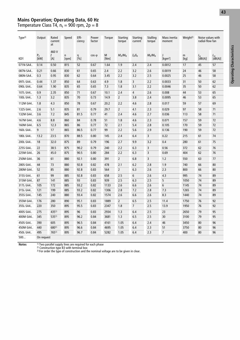
Ope
rati
ng C
hara
cter
isti
cs
43
Type3) Output Rated current at
Speed Effi-ciency
Power factor
Torque Starting torque
Starting current
Stalling torque
Mass inertia moment
Weight2) Noise values with radial-flow fan
KD1P2[kW]
460 V
I
[A]n[rpm]
η[%]
cos ϕ M[Nm]
MA/
MN
IA/
IN
MK/
MN J[kgm2]
m[kg]
Lp[dB(A)]
Lw[dB(A)]
071N-SA4.. 0.14 0.50 815 52 0.67 1.64 1.9 2.4 2.4 0.0012 17 45 57
087N-SA4.. 0.21 0.66 830 61 0.65 2.4 2.2 3.2 2.6 0.0019 24 46 58
080N-SA4.. 0.3 0.95 830 62 0.64 3.45 2.2 3.2 2.5 0.0025 25 46 58
097L-SA4.. 0.44 1.37 850 64 0.63 4.9 1.8 3 2.2 0.0033 31 50 62
090L-SA4.. 0.64 1.90 835 65 0.65 7.3 1.8 3.1 2.2 0.0046 35 50 62
107L-SA4.. 0.9 2.35 850 71 0.67 10.1 2.4 4 2.6 0.008 44 53 65
100L-SA4.. 1.3 3.2 835 70 0.73 14.9 2 3.8 2.4 0.0095 46 53 65
112M-SA4.. 1.8 4.3 850 78 0.67 20.2 2.2 4.6 2.8 0.017 59 57 69
132S-SA4.. 2.6 5.1 835 81 0.79 29.7 2 4.1 2.3 0.029 97 58 71
132M-SA4.. 3.6 7.2 845 81.5 0.77 41 2.4 4.6 2.7 0.036 113 58 71
167M-SA4.. 4.6 8.8 860 84 0.78 51 1.8 4.6 2.3 0.071 157 59 72
160M-SA4.. 6.5 12.3 865 86 0.77 72 2.1 5.4 2.8 0.105 170 59 72
160L-SA4.. 9 17 865 86.5 0.77 99 2.2 5.6 2.9 0.136 190 59 72
180L-SA4.. 13.2 23.5 870 88.5 0.80 145 2.4 6.4 3 0.22 215 61 74
200L-SA4.. 18 32.0 875 89 0.79 196 2.7 9.9 3.2 0.4 280 61 75
225S-SA4.. 22 38.5 875 90.2 0.79 240 2.2 6.3 3 0.56 372 62 76
225M-SA4.. 26 45.0 875 90.5 0.80 284 2.2 6.3 3 0.69 404 62 76
250M-SA4.. 36 61 880 92.1 0.80 391 2 6.8 3 1.2 550 63 77
280S-SA4.. 44 73 880 92.8 0.82 478 2.1 6.2 2.8 1.9 740 66 80
280M-SA4.. 52 85 880 92.8 0.83 564 2 6.3 2.6 2.3 800 66 80
315S-SA4.. 61 99 885 92.8 0.83 658 2.5 6 2.6 4.3 995 74 89
315M-SA4.. 87 141 885 93 0.83 939 2.5 6.3 2.5 5 1050 74 89
317L-SA4.. 105 172 885 93.2 0.82 1133 2.6 6.6 2.6 6 1145 74 89
315L-SA4.. 121 199 885 93.2 0.82 1306 2.8 7.2 2.8 7.3 1265 74 89
355S-SA4.. 145 240 880 93.4 0.82 1574 2.6 6.6 2.6 8.3 1440 74 89
355M-SA4.. 176 280 890 95.1 0.83 1889 2 6.5 2.5 11.4 1750 76 92
355L-SA4.. 220 350 895 95.5 0.83 2347 1.8 7 2.5 13.9 1950 76 92
400S-SA4.. 275 4351) 895 96 0.83 2934 1.3 6.4 2.5 23 2650 79 95
400M-SA4.. 345 5351) 895 96.2 0.84 3681 1.3 6.5 2.5 30 3100 79 95
450S-SA4.. 390 605 895 96.5 0.84 4161 1.05 6.4 2.4 46 3450 80 96
450M-SA4.. 440 6801) 895 96.6 0.84 4695 1.05 6.4 2.3 51 3750 80 96
450L-SA4.. 495 7651) 895 96.7 0.84 5282 1.05 6.4 2.3 7 400 80 96
500... On request
Notes 1) Two parallel supply lines are required for each phase 2) Construction type B3 with terminal box3) For order the type of construction and the nominal voltage are to be given in clear.
Mains Operation; Operating Data, 60 HzTemperature Class T4, ns = 900 rpm, 2p = 8
Ff01e03g.fm Seite 43 Montag, 17. September 2001 9:47 09

Ope
rati
ng C
hara
cter
isti
cs44
Ambient temperature 40 °C, increased winding temperature within thermal class F
Type2) Output Rated current at
Speed Effi-ciency
Power factor
Torque Starting moment
Starting current
Stalling torque
Mass inertia moment
Weight1) Noise values with radial-flow fan
KD1P2[kW]
400 V
I [A]
500 V
I [A]
n[rpm]
h
[%]cos
v M[Nm]
MA/
MN
IA/
IN
MK/
MN J[kgm2]
m[kg]
Lp[dB(A)]
Lw[dB(A)]
067N-AA4.. 0.25 0.78 0.62 2650 58 0.80 0.90 2 3 3.5 0.00028 16 54 66
063N-AA4.. 0.37 1.09 0.87 2660 60 0.82 1.33 2 3.1 3.5 0.00028 16 54 66
077N-AA4.. 0.46 1.43 1.15 2720 66 0.84 1.93 2.1 4.2 2.5 0.00028 16 57 69
071N-AA4.. 0.75 1.91 1.53 2730 70 0.81 2.62 2.7 4.7 3.2 0.00039 17 57 69
087N-AA4.. 1.0 2.65 2.1 2750 68 0.80 3.47 2.4 4.2 3 0.00058 24 59 71
080N-AA4.. 1.4 3.75 3.0 2790 72 0.75 4.8 2.8 4.7 3.4 0.0008 25 59 71
097L-AA4.. 1.9 4.2 3.35 2830 77.8 0.84 6.4 2.2 5.8 3.1 0.0013 31 60 72
090L-AA4.. 2.7 6.2 4.95 2830 78 0.81 9.1 2.5 5.5 3.5 0.0018 35 60 72
100L-AA4.. 3.4 7.5 6.0 2845 80 0.82 11.4 2.8 5.8 3.5 0.0029 45 64 76
112M-AA4.. 5.0 10.4 8.3 2875 82 0.85 16.6 2.7 6 2.9 0.0051 53 66 78
137S-AA4.. 6.6 14.3 11.4 2880 81.5 0.82 21.9 2.4 6 3.1 0.0089 95 69 82
132S-AA4.. 9.0 19.4 15.6 2900 83.5 0.80 29.6 2.7 6.5 3.5 0.0125 100 69 82
167M-AA4.. 13.5 26 21 2920 86 0.87 44 2.5 6.5 3.2 0.032 163 80 93
160M-AA4.. 18.5 34.5 27.5 2910 87.5 0.89 61 2.5 6.5 3.2 0.043 173 80 93
160L-AA4.. 22 39.5 31.5 2915 89 0.90 72 2.8 6.9 3.4 0.052 188 80 93
180M-AA4.. 30 55 44 2915 89.5 0.88 98 2.7 6.9 3.1 0.075 196 83 96
207L-AA4.. 37 66 53 2955 91.4 0.89 120 3 7.2 3.3 0.13 254 85 99
200L-AA4.. 45 81 65 2955 92 0.87 145 2.8 7.2 3.3 0.16 278 85 99
225M-AA4.. 55 103 83 2965 91.5 0.84 177 2.9 7.1 3.7 0.24 400 87 101
250M-AA4.. 70 134 107 2975 92.2 0.82 225 2.7 6.9 3.5 0.4 545 87 101
280S-AA4.. 90 159 127 2970 92 0.89 289 2 6.6 3 0.65 700 89 103
280M-AA4.. 110 195 156 2970 92.4 0.88 354 2.1 6.9 3.1 0.78 762 89 103
315S-AA4.. 132 235 187 2975 92.5 0.88 424 1.9 6.3 2.5 1.4 960 90 105
315M-AA4.. 160 280 225 2975 93 0.89 514 1.8 6.7 2.4 1.6 1025 90 105
317L-AA4.. 200 320 255 2975 93.5 0.89 594 2 6.9 2.6 1.9 1065 90 105
315L-AA4.. 230 400 320 2975 93.5 0.89 738 2 6.9 2.6 2.2 1270 90 105
Notes 1) Construction type B3 with terminal box2) For order the type of construction and the nominal voltage are to be given in clear.
Mains Operation; Operating Data, 50 Hz Increased OutputTemperature Class T4, ns = 3000 rpm, 2p = 2
Ff01e03g.fm Seite 44 Montag, 17. September 2001 9:47 09

Ope
rati
ng C
hara
cter
isti
cs
45
Ambient temperature 40 °C, increased winding temperature within thermal class F
Type3) Output Rated current at
Speed Effi-ciency
Power factor
Torque Starting moment
Starting current
Stalling torque
Mass inertia moment
Weight2) Noise values with radial-flow fan
KD1P2 [kW]
400 V
I
[A]
500 V
I [A]
n[rpm]
h
[%]cos
v M[Nm]
MA/
MN
IA/
IN
MK/
MN J[kgm2]
m[kg]
Lp[dB(A)]
Lw[dB(A)]
067N-BA4.. 0.18 0.62 0.50 1250 54 0.77 1.38 1.7 2.5 2.2 0.00046 16 45 57
063N-BA4.. 0.25 0.80 0.64 1280 58 0.78 1.87 1.7 2.8 2.5 0.00046 16 45 57
077N-BA4.. 0.37 1.17 0.93 1325 61 0.75 2.67 1.7 3 2.3 0.00046 16 46 58
071N-BA4.. 0.5 1.57 1.25 1310 65 0.78 4.0 1.7 3.3 2.3 0.00063 17 46 58
087N-BA4.. 0.7 1.99 1.59 1310 65 0.78 5.1 2 3.5 2.2 0.00092 24 47 59
080N-BA4.. 1.0 2.7 2.15 1350 70 0.77 7.1 2.3 4.1 2.5 0.0013 25 47 59
097L-BA4.. 1.4 3.35 2.7 1350 73.5 0.82 9.9 1.9 4.2 2.2 0.0021 31 49 61
090L-BA4.. 2.0 4.7 3.75 1360 74 0.83 14 2 4.2 2.2 0.0029 35 49 61
107L-BA4.. 2.5 6.2 4.9 1415 76 0.77 16.9 2.3 5.3 2.7 0.0046 44 52 64
100L-BA4.. 3.4 7.4 5.9 1400 78.8 0.85 23.2 2.1 5.1 2.8 0.0056 46 52 64
112M-BA4.. 5.0 11.1 8.9 1420 81 0.80 33.6 2.6 6.4 3 0.011 59 54 66
132S-BA4.. 6.6 13.3 10.5 1445 85.1 0.84 44 2.6 6.3 2.9 0.022 100 59 72
132M-BA4.. 9.0 18.3 14.6 1435 85.7 0.83 60 2.7 6.3 3 0.03 110 59 72
160M-BA4.. 13.5 29.5 23.5 1450 86.5 0.77 89 2.6 6.1 3 0.057 168 67 80
160L-BA4.. 17.5 34.0 27.0 1450 88.5 0.84 115 2.5 6.2 2.9 0.079 184 67 80
180M-BA4.. 22 43.5 35.0 1460 90 0.81 144 3.1 6.7 3.2 0.13 198 73 86
180L-BA4.. 27 52 42.0 1460 91 0.82 177 3 7.2 3.1 0.155 217 73 86
200L-BA4.. 37 68 55 1460 91 0.86 242 2.9 6.9 3 0.25 274 76 90
225S-BA4.. 45 81 65 1465 92 0.87 293 2.6 6.1 2.6 0.4 372 79 93
225M-BA4.. 55 100 80 1475 92.5 0.86 356 2.6 6.3 2.8 0.48 402 79 93
250M-BA4.. 70 127 102 1475 92.5 0.86 453 2.9 7.2 3.4 0.75 573 80 94
280S-BA4.. 90 164 131 1480 93.2 0.85 581 2.7 6.8 2.8 1.25 740 82 96
280M-BA4.. 110 200 161 1480 93.7 0.84 710 2.9 6.9 3.1 1.48 820 82 96
315S-BA4.. 132 235 190 1485 94.6 0.85 849 2.2 6.5 2.4 2.2 1040 84 99
315M-BA4.. 160 285 225 1485 94.5 0.86 1029 2.4 6.8 2.6 2.7 1120 84 99
317L-BA4.. 200 330 260 1485 94.7 0.86 1190 2.5 6.9 2.6 3.3 1210 84 99
315L-BA4.. 230 4101) 325 1485 94.7 0.86 1479 2.5 6.9 2.7 3.9 1430 84 99
Notes 1) Two parallel supply lines are required for each phase2) Construction type B3 with terminal box3) For order the type of construction and the nominal voltage are to be given in clear.
Mains Operation; Operating Data, 50 Hz Increased OutputTemperature Class T4 ns = 1500 rpm, 2p = 4
Ff01e03g.fm Seite 45 Montag, 17. September 2001 9:47 09

Ope
rati
ng C
hara
cter
isti
cs46
Ambient temperature 40 °C, increased winding temperature within thermal class F
Type2) Output Rated current at
Speed Effi-ciency
Power factor
Torque Starting moment
Starting current
Stalling torque
Mass inertia moment
Weight1) Noise values with radial-flow fan
KD1P2 [kW]
460 V
I
[A]n[rpm]
h
[%]cos
v M[Nm]
MA/
MN
IA/
IN
MK/
MN J[kgm2]
m[kg]
Lp[dB(A)]
Lw[dB(A)]
067N-PA4.. 0.29 0.78 3180 58 0.80 0.87 2 3 3.5 0.00028 16 57 69
063N-PA4.. 0.43 1.09 3190 60 0.82 1.29 2 3.1 3.5 0.00028 16 57 69
077N-PA4.. 0.53 1.45 3265 66 0.84 1.87 2.1 4.2 2.5 0.00028 16 61 73
071N-PA4.. 0.87 1.93 3375 70 0.81 2.46 2.7 4.7 3.2 0.00039 17 61 73
087N-PA4.. 1.16 2.7 3300 68 0.80 3.36 2.4 4.2 3 0.00058 24 63 75
080N-PA4.. 1.6 3.7 3350 72 0.75 4.6 2.8 4.7 3.4 0.0008 25 63 75
097L-PA4.. 2.2 4.25 3395 77.5 0.84 6.3 2.2 5.8 3.1 0.0013 31 64 76
090L-PA4.. 3.1 6.2 3395 78 0.81 8.7 2.5 5.5 3.5 0.0018 35 64 76
100L-PA4.. 3.9 7.5 3415 80 0.82 10.9 2.8 5.8 3.5 0.0029 45 68 80
112M-PA4.. 5.8 10.4 3450 82 0.85 16.1 2.7 6 2.9 0.0051 53 70 82
137S-PA4.. 7.6 14.3 3455 81.5 0.82 21 2.4 6 3.1 0.0089 95 73 86
132S-PA4.. 10.4 18.1 3505 84.5 0.86 28.5 2.7 6.5 3.5 0.0125 100 73 86
167M-PA4.. 15.5 26 3505 86 0.87 42 2.5 6.5 3.2 0.034 163 85 98
160M-PA4.. 22 35.5 3490 87.5 0.89 60 2.5 6.5 3.2 0.043 173 85 98
160L-PA4.. 26 41 3500 89 0.90 71 2.8 6.9 3.4 0.052 188 85 98
180M-PA4.. 35 56 3500 89.5 0.88 96 2.7 6.9 3.1 0.075 196 88 101
207L-PA4.. 43 67 3545 91 0.88 116 3 7.2 3.3 0.13 254 90 104
200L-PA4.. 52 82 3545 92 0.87 140 2.8 7.2 3.3 0.16 278 90 104
225M-PA4.. 64 105 3560 91.5 0.84 172 2.9 7.1 3.7 0.24 400 92 106
250M-PA4.. 81 135 3570 92 0.82 217 2.7 6.9 3.5 0.4 545 92 106
280S-PA4.. 105 161 3565 92 0.89 281 2 6.6 3 0.65 700 95 109
280M-PA4.. 121 187 3565 92.2 0.88 324 2 7.3 3.3 0.78 762 95 109
315S-PA4.. 145 225 3570 92.3 0.88 388 1.9 6.6 2.6 1.4 960 96 111
315M-PA4.. 176 265 3570 92.8 0.89 471 1.8 7.1 2.5 1.6 1025 96 111
317L-PA4.. 220 310 3570 93.2 0.89 548 2 7.3 2.7 1.9 1065 96 111
315L-PA4.. 255 385 3570 93.2 0.89 682 2 7.3 2.7 2.2 1270 96 111
Notes 1) Construction type B3 with terminal box2) For order the type of construction and the nominal voltage are to be given in clear.
Mains Operation; Operating Data, 60 Hz Increased OutputTemperature Class T4, ns = 3600 rpm, 2p = 2
Ff01e03g.fm Seite 46 Montag, 17. September 2001 9:47 09

Ope
rati
ng C
hara
cter
isti
cs
47
Ambient temperature 40 °C, increased winding temperature within thermal class F
Type2) Output Rated current at
Speed Effi-ciency
Power factor
Torque Starting moment
Starting current
Stalling torque
Mass inertia moment
Weight1) Noise values with radial-flow fan
KD1P2 [kW]
460 V
I
[A]n[rpm]
h
[%]cos
v M[Nm]
MA/
MN
IA/
IN
MK/
MN J[kgm2]
m[kg]
Lp[dB(A)]
Lw[dB(A)]
067N-QA4.. 0.21 0.63 1500 54 0.77 1.34 1.7 2.5 2.2 0.00046 16 48 60
063N-QA4.. 0.29 0.80 1535 58 0.78 1.8 1.7 2.8 2.5 0.00046 16 48 60
077N-QA4.. 0.43 1.18 1590 61 0.75 2.58 1.7 3 2.3 0.00046 16 49 61
071N-QA4.. 0.58 1.58 1570 65 0.78 3.9 1.7 3.3 2.3 0.00063 17 49 61
087N-QA4.. 0.81 2.0 1570 65 0.78 4.9 2 3.5 2.2 0.00092 24 50 62
080N-QA4.. 1.16 2.7 1620 70 0.77 6.8 2.3 4.1 2.5 0.0013 25 50 62
097L-QA4.. 1.6 3.35 1620 73.5 0.82 9.4 1.9 4.2 2.2 0.0021 31 52 64
090L-QA4.. 2.3 4.7 1630 74 0.83 13.5 2 4.2 2.2 0.0029 35 52 64
107L-QA4.. 2.9 6.2 1700 76 0.77 16.3 2.3 5.3 2.7 0.0046 44 55 67
100L-QA4.. 3.9 7.3 1680 78.8 0.85 22.2 2.1 5.1 2.8 0.0056 46 55 67
112M-QA4.. 5.8 11.2 1705 81 0.80 32.5 2.6 6.4 3 0.011 59 57 69
132S-QA4.. 7.6 13.3 1735 85.1 0.84 42 2.6 6.3 2.9 0.022 100 63 76
132M-QA4.. 10.4 18.4 1720 85.7 0.83 58 2.7 6.3 3 0.03 110 63 76
160M-QA4.. 15.5 29 1740 86.5 0.77 85 2.6 6.1 3 0.057 168 71 84
160L-QA4.. 20 34 1740 88.5 0.84 110 2.5 6.2 2.9 0.079 184 71 84
180M-QA4.. 26 45 1750 90 0.81 142 3.1 7 3.2 0.13 198 76 89
180L-QA4.. 31 52 1755 90.8 0.83 169 3 7.2 3.1 0.155 217 76 89
200L-QA4.. 43 69 1750 91 0.86 235 2.9 6.9 3 0.25 274 81 95
225S-QA4.. 52 82 1760 92 0.87 282 2.6 6.1 2.6 0.4 372 84 98
225M-QA4.. 64 102 1770 92 0.86 345 2.6 6.3 2.8 0.48 402 84 98
250M-QA4.. 81 128 1770 92.5 0.86 437 2.9 7.2 3.4 0.75 573 85 99
280S-QA4.. 105 167 1775 93 0.85 565 2.7 6.8 2.8 1.25 740 87 101
280M-QA4.. 121 193 1775 93.5 0.84 651 3.1 7.3 3.3 1.48 820 87 101
315S-QA4.. 145 235 1780 94.4 0.85 778 2.3 6.9 2.5 2.2 1040 89 104
315M-QA4.. 176 285 1780 94.3 0.86 944 2.5 7.2 2.7 2.7 1120 89 104
317L-QA4.. 220 315 1780 94.5 0.86 1100 2.6 7.3 2.7 3.3 1210 89 104
315L-QA4.. 255 395 1780 94.5 0.86 1368 2.6 7.3 2.8 3.9 1430 89 104
Notes 1) Construction type B3 with terminal box2) For order the type of construction and the nominal voltage are to be given in clear.
Mains Operation; Operating Data, 60 Hz Increased OutputTemperature Class T4, ns = 1800 rpm, 2p = 4
Ff01e03g.fm Seite 47 Montag, 17. September 2001 9:47 09

Mains Operation; Power Assignment, 50 Hz/60 HzTemperature Class T6
Ope
rati
ng C
hara
cter
isti
cs48
50 Hz 60 Hz
Type
KD1
2p = 23000 rpmP2[kW]
2p = 41500 rpmP2[kW]
2p = 61000 rpmP2[kW]
2p = 8750 rpmP2[kW]
2p = 23600 rpmP2[kW]
2p = 41800 rpmP2[kW]
2p = 61200 rpmP2[kW]
2p = 8900 rpmP2[kW]
067N-..6.. 0.18 0.12 0.21 0.14
063N-..6.. 0.25 0.18 0.29 0.21
077N-..6.. 0.37 0.25 0.44 0.3
071N-..6.. 0.55 0.37 0.25 0.12 0.65 0.44 0.25 0.14
087N-..6.. 0.75 0.55 0.37 0.18 0.86 0.63 0.42 0.21
080N-..6.. 1.1 0.75 0.55 0.25 1.26 0.86 0.64 0.29
097L-..6.. 1.5 1.1 0.65 0.37 1.8 1.3 0.75 0.43
090L-..6.. 2.2 1.4 0.85 0.55 2.5 1.6 1 0.64
107L-..6.. 2.5 1.8 1.3 0.75 2.9 2.1 1.5 0.87
100L-..6.. 2.2 0.95 2.3 1.1
112M-..6.. 3.5 3.5 2 1.3 4 4 2.3 1.5
137S-..6.. 5.5 5.8
132S-..6.. 6 5 3 1.9 7 5.5 3.5 2.2
137M-..6.. 6 4 2.5 6.5 4.6 2.9
132M-..6.. 4.7 5.4
167M-..6.. 9 3.5 10.5 4
160M-..6.. 12 9.5 6.5 5 14 11 7.5 5.8
160L-..6.. 13 11 8.5 6.5 15 12.5 9.8 7.5
180M-..6.. 16.5 14 19 16
180L-..6.. 15 10 9.5 17.5 11.5 11
207L-..6.. 22 22 15 12 25.5 25.5 17.5 14
200L-..6.. 27 18 31 21
225S-..6.. 30 15 34 17.5
225M-..6.. 35 35 22 19 40 40 29 22
250M-..6.. 39 39 33 27 45 45 38 31
280S-..6.. 60 60 40 33 69 69 46 38
280M-..6.. 75 70 45 40 87 81 52 46
315S-..6.. On request On request
315M-..6..
317L-..6..
315L-..6..
318L-..6..
355M-..6..
357L-..6.. On request On request
355L-..6..
Ff01e03g.fm Seite 48 Montag, 17. September 2001 9:47 09

Ope
rati
ng C
hara
cter
isti
cs
49
Ambient temperature 40°C, increased winding temperature within thermal class F
Type3) Output Rated current at
Speed Effi-ciency
Power factor
Torque Starting moment
Starting current
Stalling torque
Mass inertia moment
Weight2) Noise values with radial-flow fan
400 V
I [A]
500 V
I [A]KD1
P2 [kW]
n [rpm]
h
[%]cos
v M [Nm]
MA/
MN
IA/
IN
MK/
MN J[kgm2]
m[kg]
Lp[dB(A)]
Lw[dB(A)]
087N-GA4.. 0.5 1.43 1.14 1400 67.5 0.75 3.4 2 3.9 2.6 0.00111 23 47 590.65 1.66 1.33 2810 63.5 0.89 2.2 2.2 4.2 3 65 77
080N-GA4.. 0.7 1.92 1.54 1400 70 0.75 4.8 2.1 4 2.7 0.00148 24 47 590.85 2.15 1.71 2820 66 0.87 2.9 2.4 4.8 3.2 65 77
097L-GA4.. 1.1 2.7 2.15 1395 70 0.84 7.5 1.8 4.2 2.2 0.00238 27 52 641.4 3.15 2.5 2820 70 0.92 4.7 1.9 4.9 3 69 81
090L-GA4.. 1.5 3.55 2.8 1400 74 0.83 10.2 2 4.7 2.3 0.00318 30 52 641.9 4.1 3.25 2830 73 0.92 6.4 2.2 5.4 3 69 81
100L-GA4.. 2.6 5.9 4.7 1410 78 0.82 17.6 2 4.8 2.7 0.00608 37 55 673.2 6.5 5.2 2870 78 0.91 10.6 2.1 5.8 3 75 87
112M-GA4.. 3.7 7.6 6.1 1430 82.5 0.85 24.7 2.2 6 3 0.0122 53 56 684.4 8.9 7.1 2895 78.5 0.91 14.5 2.5 6.7 3.3 76 88
132S-GA4.. 5 10.4 8.3 1440 83 0.84 33 2.1 5 2.9 0.0238 100 62 756 12.0 9.6 2910 79 0.91 19.7 2.5 6.4 2.9 80 93
132M-GA4.. 7 14.2 11.3 1440 84 0.85 46 2.6 5.8 2.8 0.0323 110 62 759 17.3 13.6 2910 83 0.92 29.5 2.5 6.8 3 80 93
160M-GA4.. 9.5 18.7 14.9 1455 87.5 0.84 62 2.5 6 2.8 0.0625 153 57 7011 19.8 15.9 2930 87 0.92 36 2.7 6.8 3.1 68 81
160L-GA4.. 13 25.0 20.0 1455 88.5 0.84 85 2.3 6 2.8 0.085 168 57 7016 28.5 23.0 2930 87.5 0.92 52 2.6 6.8 3.2 68 81
180M-GA4.. 16.5 32.0 25.5 1460 89.5 0.83 108 2.8 6.5 2.7 0.13 185 58 7120 36.5 29.0 2930 88 0.90 65 2.8 6.9 3 69 82
180L-GA4.. 19 36.5 29.5 1465 90 0.83 124 3.1 6.5 2.9 0.155 195 58 7125 45.5 36.0 2940 88.5 0.90 81 3.1 6.8 3.2 69 82
200L-GA4.. 26 47.0 37.5 1470 91.5 0.87 169 2.8 6.6 3 0.25 270 60 7431 53 43.0 2955 90 0.93 100 2.7 7.1 3.5 73 87
225S-GA4.. 32 59 47.0 1470 91.5 0.86 208 2.6 6.5 2.5 0.4 369 61 7538 66 53 2955 90 0.92 123 2.6 7 3 74 88
225M-GA4.. 38 69 55 1470 92.5 0.86 247 2.8 6.5 2.7 0.48 400 61 7546 79 63 2955 91.5 0.92 149 2.8 7 3.2 74 88
250M-GA4.. 46 82 65 1470 92.5 0.88 299 2.7 6.5 2.8 0.75 570 63 77
55 94 75 2955 91 0.93 178 2.9 7.1 3.3 76 90
280S-GA4.. 63 113 90 1480 93.5 0.86 407 2.8 6.5 2.5 1.25 730 65 7975 129 103 2475 92 0.91 241 2.6 7 3.1 78 92
280M-GA4.. 73 131 105 1485 93.5 0.86 469 2.8 6.5 2.6 1.48 800 65 7987 150 120 2970 92 0.91 280 2.4 7.1 3.2 78 92
315S-GA4.. 85 155 124 1485 94 0.84 547 2.5 6.5 2.4 2.2 996 67 82100 174 139 2975 92 0.90 321 2.1 7 2.8 80 95
315M-GA4.. 100 179 143 1485 95 0.85 643 2.6 6.6 2.6 2.7 1096 67 82125 215 172 2975 92 0.91 401 2.3 7.1 3 80 95
317L-GA4.. 120 215 172 1485 95 0.85 772 2.6 6.5 2.4 3.3 1221 67 82150 260 205 2975 92 0.91 482 2.3 7 2.9 80 95
315L-GA4.. 145 260 205 1485 95 0.85 932 2.6 6.5 2.4 3.8 1290 67 82175 300 240 2975 92 0.91 562 2.3 7 2.9 80 95
355S-GA4.. 160 280 220 1485 95.5 0.87 1029 1.3 6.4 2.4 5.1 1800 70 86200 330 265 2980 94 0.93 641 1.4 6.9 2.7 82 98
357M-GA4.. 180 315 250 1485 95.5 0.87 1158 1.3 6.6 2.3 5.6 1900 70 86220 365 290 2980 94 0.93 705 1.3 7.1 2.6 82 98
355M-GA4.. 200 345 280 1485 95.5 0.87 1286 1.3 6.5 2.3 6 2050 70 86250 415 330 2985 94 0.93 800 1.3 7 2.6 82 98
355L-GA4.. 220 380 305 1485 96 0.87 1415 1.3 6.5 2.3 6.7 2200 70 86280 4601) 370 2985 94.5 0.93 896 1.3 7 2.6 82 98
Notes 1) Two parallel supply lines are required for each phase2) Construction type B3 with terminal box3) For order the type of construction and the nominal voltage are to be given in clear.
Mains Operation; Operating Data, 50 Hz Pole-Changing MotorsTemperature class T4, ns = 1500/3000 rpm, 2p = 4/2
Ff01e03g.fm Seite 49 Montag, 17. September 2001 9:47 09

Ope
rati
ng C
hara
cter
isti
cs50
Ambient temperature 40 °C, increased winding temperature within thermal class F
Type2) Output Rated current at
Speed Effi-ciency
Power factor
Torque Starting moment
Starting current
Stalling torque
Mass inertia moment
Weight1) Noise values with radial-flow fan
400 V
I [A]
500 V
I [A]KD1
P2 [kW]
n[rpm]
h
[%]cos
v M[Nm]
MA/
MN
IA/
IN
MK/
MN J[kgm2]
m[kg]
Lp[dB(A)]
Lw[dB(A)]
097L-JA4.. 0.45 1.40 1.12 930 62 0.75 4.6 1.6 3 2.3 0.0038 27 52 64
0.65 1.56 1.25 1430 75 0.80 4.3 1.8 4 2.4 55 67
090L-JA4.. 0.6 1.83 1.47 940 63 0.75 6.1 1.6 3.1 2.1 0.0051 30 52 64
0.9 2.15 1.72 1430 75.5 0.80 6 1.9 4.2 2.3 55 67
107L-JA4.. 0.9 2.55 2.05 945 67.5 0.76 9.2 1.7 3.9 2.2 0.008 39 53 65
1.3 3.05 2.45 1450 76.5 0.8 8.7 1.8 5.9 2.8 57 69
100L-JA4.. 1.1 3.10 2.5 950 69 0.74 11.3 1.9 4 2.3 0.0105 41 53 65
1.7 4.0 3.2 1445 76 0.81 11.3 1.9 5.5 2.4 57 69
112M-JA4.. 1.5 3.5 2.8 950 77.6 0.8 15.1 2 4.6 2.3 0.019 53 54 66
2.4 5.0 4.0 1430 79 0.88 15.8 1.8 4.8 2.4 59 71
132S-JA4.. 2.2 5.2 4.2 960 75 0.81 21.9 1.6 4.6 2.1 0.033 97 59 72
3.3 7.1 5.7 1450 78 0.86 21.7 1.7 5.9 2.3 62 75
132M-JA4.. 3 6.9 5.5 960 78 0.81 29.8 1.8 4.5 2.4 0.046 107 59 72
4.5 9.1 7.2 1445 81.5 0.88 29.4 1.6 5.8 2.7 62 75
160M-JA4.. 4.5 9.8 7.9 970 80.5 0.82 44.5 2.1 6.5 2.9 0.095 143 64 77
6.6 12.8 10.2 1445 82 0.91 43 1.8 6.4 2.7 70 83
160L-JA4.. 6.5 13.2 10.5 960 81 0.88 64 1.6 5.2 2.5 0.13 163 64 77
9.5 17.7 14.2 1465 86 0.90 62 2.1 6.9 2.7 70 83
180L-JA4.. 11 22.5 18.0 975 86 0.82 102 2.4 7 3.2 0.155 190 56 69
16 29.0 23.5 1465 88 0.90 104 2 6.9 2.6 63 76
200L-JA4.. 16 32.5 26 975 86.5 0.82 157 1.8 7 2.8 0.338 275 56 70
24 43.5 35 1475 89 0.89 156 1.6 7 3.1 63 77
225S-JA4.. 21 39.5 31.5 975 89 0.86 206 2.6 6.1 2.3 0.4 380 60 74
31 54 43.0 1470 90 0.92 201 2.1 6.6 2.8 67 81
225M-JA4.. 25 46.5 37.0 975 89.5 0.87 245 2.8 6 2.4 0.48 400 60 74
37 64 51 147 91 0.92 240 2.2 6.8 2.9 67 81
250M-JA4.. 32 59 47.0 975 90 0.87 313 2.7 6 2.5 0.75 570 61 75
47 81 65 1475 91 0.92 304 2.2 6.4 2 68 82
280S-JA4.. 45 88 70 980 91 0.81 439 2.8 6.3 2.7 1.02 730 62 76
66 108 86 1480 92.5 0.87 426 2.6 6.9 2.7 70 84
280M-JA4.. 54 107 86 980 91 0.80 526 2.8 6.7 2.7 1.27 800 62 76
80 142 113 1475 92.5 0.88 516 2.6 7 3 70 84
315S-JA4.. 60 112 90 985 92 0.84 582 2 6.5 2.3 2.2 996 63 78
85 147 117 1480 93 0.90 547 2.3 6.9 2.1 71 86
315M-6/4 70 130 104 985 92.5 0.84 679 2 6.5 2.3 2.7 1096 63 78
100 172 138 1480 93 0.90 643 2.3 6.9 2.2 71 86
317L-JA4.. 85 157 126 985 93 0.84 824 2.2 6.8 2.4 3.3 1221 63 78
120 205 164 1480 94 0.90 772 2.4 7 2.2 71 86
315L-JA4.. 100 182 145 985 93.5 0.85 970 2.2 6.8 2.4 3.9 1290 63 78
140 235 189 1485 95 0.90 900 2.4 7 2.2 71 86
355S-JA4.. 110 192 154 985 94 0.88 1067 1.7 6.5 2.2 8.9 1750 67 83
160 265 215 1485 95 0.91 1029 1.6 6.8 2 76 92
355M-JA4.. 130 225 181 985 94 0.88 1260 1.7 6.8 2.3 10.9 1950 67 83
180 300 240 1485 95 0.91 1152 1.6 7 2.1 76 92
355L-JA4.. 150 260 210 990 94.5 0.88 1454 1.6 6.5 2.2 12.6 2200 67 83
210 350 280 1485 95 0.91 1351 1.6 6.9 2.1 76 92
Notes 1) Construction type B3 with terminal box2) For order the type of construction and the nominal voltage are to be given in clear.
Mains Operation; Operating Data, 50 Hz Pole-Changing MotorsTemperature Class T4, ns = 1000/1500 rpm, 2p = 6/4
Ff01e03g.fm Seite 50 Montag, 17. September 2001 9:47 09

Ope
rati
ng C
hara
cter
isti
cs
51
Ambient temperature 40 °C, increased winding temperature within thermal class F
Type3) Output Rated current at
Speed Effi-ciency
Power factor
Torque Starting moment
Starting current
Stalling torque
Mass inertia moment
Weight2) Noise values with radial-flow fan
400 V
I [A]
500 V
I [A]KD1
P2 [kW]
n[rpm]
h
[%]cos
v M[Nm]
MA/
MN
IA/
IN
MK/
MN J[kgm2]
m[kg]
Lp[dB(A)]
Lw[dB(A)]
097L-HA4.. 0.4 1.48 1.18 675 56.5 0.69 5.7 1.5 2.7 2 0.0038 27 49 61
0.6 1.40 1.12 1400 70.5 0.88 4.1 2 4.4 2.5 52 64
090L-HA4.. 0.55 2.0 1.61 680 58 0.68 7.7 1.7 3.3 2.2 0.0051 30 49 61
0.8 1.87 1.50 1410 71 0.87 5.4 2 4.2 2.6 52 64
107L-HA4.. 0.9 3.05 2.45 690 60 0.71 12.5 1.6 3.1 2.1 0.008 36 52 64
1.3 3.1 2.45 1395 67.5 0.90 8.9 1.6 4.2 2.2 5 17
100L-HA4.. 1 3.1 2.5 700 65.5 0.71 13.6 1.7 3.5 2.2 0.011 39 52 64
1.6 3.5 2.8 1400 72 0.91 10.9 1.7 4.5 2.4 55 67
112M-HA4.. 1.5 4.6 3.65 710 72.6 0.65 20.2 2.1 4.2 2.2 0.019 53 52 64
2.5 4.85 3.85 1420 83 0.9 16.8 1.8 5.2 2.3 56 68
132S-HA4.. 2.3 6.8 5.4 715 74 0.66 30.7 1.7 4.2 2.6 0.0325 92 53 66
3.6 7.3 5.8 1435 80.5 0.89 24 1.8 5.3 2.5 62 75
132M-HA4.. 3 8.1 6.5 720 80 0.67 40 1.9 4.6 2.7 0.046 102 53 66
5 9.5 7.6 1435 84.5 0.90 33.3 1.9 5.8 2.6 62 75
167M-HA4.. 4.7 11.5 9.2 720 81 0.73 62 1.7 4.7 2.5 0.081 133 54 67
5.5 12.1 9.7 1445 76.5 0.86 36.3 2.1 5.7 3 66 79
160M-HA4.. 5.5 12.1 9.7 715 83 0.79 73 1.7 4.6 2.2 0.108 153 54 67
7.5 14.8 11.9 1440 81 0.90 50 2 6.1 2.8 66 79
160L-HA4.. 7 16.3 13.0 720 84 0.74 93 2 5.5 2.7 0.145 140 54 67
11 22.0 17.5 1445 81.5 0.89 73 2 6.6 3 66 79
180L-HA4.. 11 25.0 19.8 725 86.5 0.74 145 2.2 6 2.8 0.243 185 53 66
18 32.0 25.5 1460 88.5 0.92 118 2.1 6.9 3.2 63 76
200L-HA4.. 17 39.5 31.5 730 88.5 0.70 222 2.2 6.4 3.5 0.438 275 53 67
27 47.0 37.5 1470 91 0.91 175 2.2 7.1 3.8 63 77
225S-HA4.. 22 47.5 38.0 735 89.5 0.75 286 2.3 6.4 3.3 0.625 379 56 70
32 56 45.0 1475 90.5 0.91 207 2.1 7.2 3.5 67 81
225M-HA4.. 26 53 43.0 730 90 0.78 340 2.4 6.5 3.4 0.75 390 56 70
38 65 52 1470 91 0.93 247 2.5 7.2 3.6 67 81
250M-HA4.. 32 64 51 735 90.5 0.80 415 1.9 6.4 2.9 1.28 570 55 69
47 79 63 1475 92 0.93 304 2 7.1 3.3 68 82
280S-HA4.. 42 85 68 735 91.5 0.78 546 2.1 6.4 2.5 2.0 740 58 72
60 101 81 1475 92.5 0.93 388 2.1 6.8 3.1 70 84
280M-HA4.. 50 98 78 735 92 0.80 650 2.1 6.5 2.4 2.4 810 58 72
72 120 96 1475 93 0.93 466 2 6.9 3 70 84
315S-HA4.. 60 114 91 740 92.5 0.82 774 2.6 6.5 2.5 4.4 996 67 82
90 150 120 1480 93 0.93 581 2.5 7 2.7 79 94
315M-HA4.. 75 143 114 740 92.5 0.82 968 2.6 6.3 2.5 5.4 1096 67 82
110 184 147 1480 93 0.93 710 2.5 6.8 2.7 79 94
317L-HA4.. 90 170 136 740 93 0.82 1161 2.7 6.6 2.6 6.6 1221 67 82
132 220 175 1480 93.5 0.93 852 2.5 7.1 3 79 94
315L-HA4.. 115 215 173 740 92.5 0.83 1484 2.7 6.6 2.6 8.0 1320 67 82
160 265 215 1480 93 0.93 1032 2.6 7.1 3 79 94
355M-HA4.. 120 245 195 745 94 0.82 1666 1.3 6 2.2 8.9 1750 69 85
175 320 255 1485 94.5 0.93 1254 1.4 6.9 2.6 76 92
357L-HA4.. 140 300 240 745 94 0.82 2051 1.2 6.1 2 10.9 1950 69 85
215 395 315 1485 94.5 0.93 1543 1.3 7 2.5 76 92
355L-HA4.. 165 345 275 745 94.5 0.82 2371 1.2 6 2 12.6 2200 69 85
250 4551) 360 1490 95 0.94 1795 1.3 6.9 2.5 76 92
Notes 1) Two parallel supply lines are required for each phase 2) Construction type B3 with terminal box3) For order the type of construction and the nominal voltage are to be given in clear.
Mains Operation; Operating Data, 50 Hz Pole-Changing MotorsTemperature Class T4 ns = 750/1500 rpm, 2p = 8/4
Ff01e03g.fm Seite 51 Montag, 17. September 2001 9:47 09

Surface-Cooled Low-Voltage Motors, Self-Cooling With Radial Flow Fan
Dim
ensi
ons
52
Construction type IM B3, IM B6, IM B7, IM B8, IM V51), IM V6
Eye bolts from frame size 90Dimension AC measured across bolt headsTerminal box rotatable 4
x 90°
1) Canopy required for construction type IM V5. See dimension LE, page 55. Dimension LC increases by LE
Type A AA AB AC B BA BB C H-0.5 HA HD K K'KD1
06.N- 100 20 120 134 80 25 100 40 63 6 224 7 10
07.N- 112 30 139 145 90 25 110 45 71 10 232 7 10
08.N- 125 35 160 163 100 35 130 50 80 12 255 9.5 12
09.L- 140 40 180 183 125 40 155 56 90 12 268 9.5 12
10.L- 160 45 200 201 140 45 175 63 100 15 298 12 15
112M- 190 50 235 225 140 50 175 70 112 17 308 12 15
13.S- 216 60 266 265 140 60 187 89 132 20 411 12 1513.M- 178 225
16.M- 254 65 310 318 210 100 300 108 160 25 477 15 2016.L- 254
180M- 279 75 350 353 241 100 340 121 180 25 548 15 20180L- 279
20.L- 318 80 390 393 305 90 365 133 200 30 583 20 26
Type A AA AB AC B BA BB C H HA HD K K'KD1
225S- 356 85 450 455 286 90 370 149 225-0.5 35 633 20 26225M- 311
250M- 406 105 510 493 349 110 420 168 250-0.5 40 725 26 35
280S- 457 110 570 548 368 120 500 190 280-1 45 793 26 35280M- 419
315S- 508 150 630 635 406 210 615 216 315-1 40 899 39 30315M- 457317L- 508315L-318L-
355M- 610 130 720 725 560 150 650 254 355-1 30 1055 30 30357L- 630 720355L-
400S- 686 130 800 810 560 150 700 280 400-1 35 1095 35 35400M- 630 770
Type A AA AB AC B BA BB C H HA HD K K'KD1
450S- 760 150 900 910 630 180 790 280 450-1 36 1180 35 35450M- 710 870450L- 840 1000
GA
K
EA
Oo DC
o DB
BA
E
BC
BB
LDL
LC
F
DA
o D
AC
GC
FA
K'AAA
AB
HAHHD
Internal thread in accordance with DIN 322 D
Internal thread in accordance with DIN 322 D
Ff01f01g.fm Seite 52 Montag, 17. September 2001 9:49 09

53
Dim
ensi
ons
L LC Shaft endType No. poles No. poles LD OKD1 2 4 6.8 2 4 6.8 D, DA E, EA GA, GC F, FA DB, DC
06.N- 240 240 240 274 274 274 104 2
xM25
x1.5 11k6 23 12.5 4 M4
07.N- 276 276 276 334 334 334 111 2
xM25
x1.5 14k6 30 16 5 M5
08.N- 313 313 313 387 387 387 116 2
xM25
x1.5 19k6 40 21.5 6 M6
09.L- 364 364 364 445 445 445 137 2
xM25
x1.5 24k6 50 27 8 M8
10.L- 415 415 415 510 510 510 149 2
xM32
x1.5 28k6 60 31 8 M10
112M- 423 423 423 526 526 526 154 2
xM32
x1.5 28k6 60 31 8 M10
13.S- 529 529 529 645 645 645 226 2
xM32
x1.5 38k6 80 41 10 M1213.M-
16.M- 709 677 677 864 864 864 261 2
xM40
x1.5 42k6 110 45 12 M1616.L-
180M- 726 726 – 909 909 – 369 2
xM40
x1.5 48k6 110 51.5 14 M16180L- – 726 – 909
20.L- 789 983 390 2
xM50
x1.5 55m6 110 59 16 M20
L1) LC1) LD Shaft endType No. poles No. poles O D, DA2) E, EA2) GA, GC2) F, FA2) DB, DC2)
KD1 2 4 6 8 2 4 6, 8 2 4,6,8
2 4,6,8 2 4,6,8
2 4,6,8
2 4,6,8
2 4,6,8
225S- – 940 – 890 – 1175 1175 – 377 2
xM50
x1.5 – 60m6 – 140 – 64 – 18 – M20225M- 910 890 1115 347 55m6 110 59 16 M20
250M- 1000 1000 934 934 1250 1250 1250 482 482 2
xM63
x1.5 60m6 65m6 140 140 64 69 18 18 M20 M20
280S- 1110 1110 1110 1110 1375 1375 1375 483 483 2
xM63
x1.5 65m6 75m6 140 140 69 79.5 18 20 M20 M20280M-
315S- 1268 1298 1218 1218 1543 1573 1573 496 526 2
xM63
x1.5 65m6 80m6 140 170 69 85 18 22 M20 M20315M-317L- 1298315L- 1468 1498 1743 1773318L- 1418 1498 1773
355M- – – 1470 1470 – – 1665 526 556 2
xM80
x2 75m6 90m6 140 170 79.5 95 20 25 M20 M24357L- 1655 1685 1620 1620 1815 1865 1815355L-
400S – 1680 1680 1680 640 710 2
xM95
x2 75m6 100m6 140 210 79.5 106 20 28 M20 M24400M 1610 1760 1760 1760
L1) LC1) LD O Shaft endType No. poles No. poles D E GA F DBKD1 4 6.8 10.12 4 6 – 12 4 6 – 12
450S 1730 1730 1685 730 2
xM95
x2 100m6 110m6 210 10 116 28 M24450M 1805 1805 1765450L 1840 1840 1880
Notes 1) For V construction types: Type 400-4, 6, 8 size L, LC plus 40 mm; Type 450-4 to 12 size L, LC plus 40 mm2) For type 250 to 315-4, 6, 8, dimension DA, EA, GC, FA, DC, figures for two poles apply, from type 355 on request
Ff01f01g.fm Seite 53 Montag, 17. September 2001 9:49 09
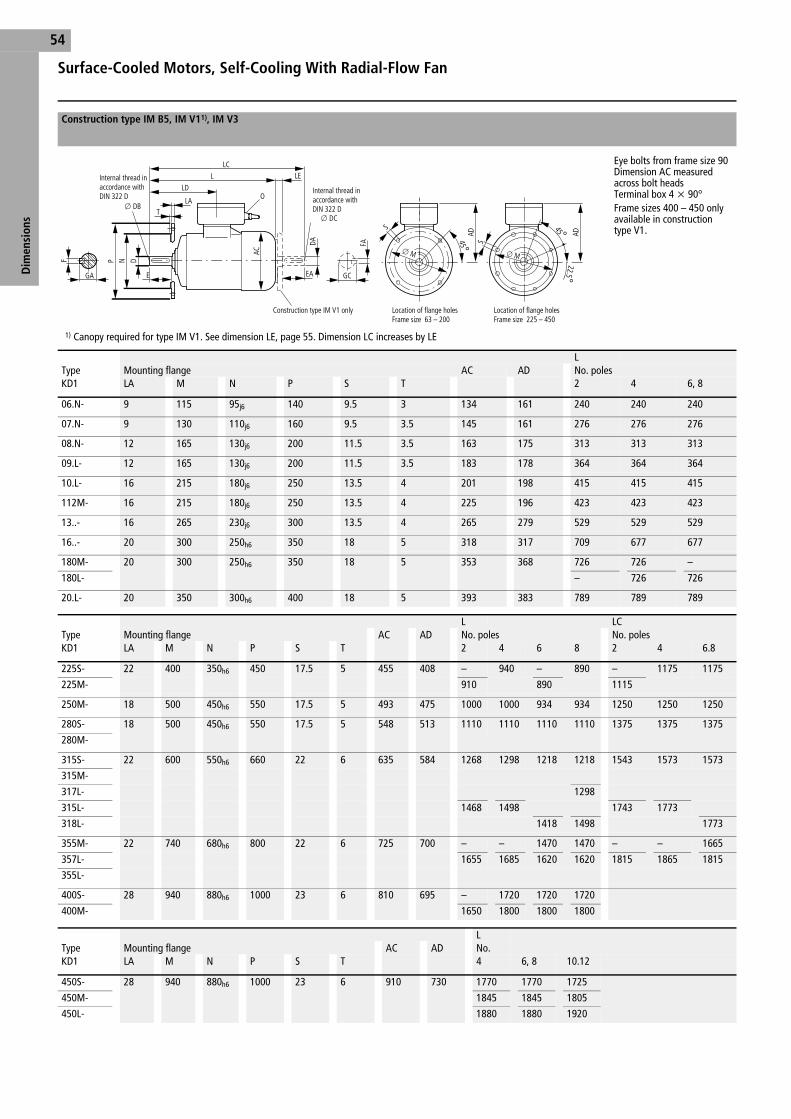
Surface-Cooled Motors, Self-Cooling With Radial-Flow Fan
Dim
ensi
ons
54
Construction type IM B5, IM V11), IM V3
Eye bolts from frame size 90Dimension AC measured across bolt headsTerminal box 4
x 90°Frame sizes 400 – 450 only available in construction type V1.
1) Canopy required for type IM V1. See dimension LE, page 55. Dimension LC increases by LE
LType Mounting flange AC AD No. polesKD1 LA M N P S T 2 4 6, 8
06.N- 9 115 95j6 140 9.5 3 134 161 240 240 240
07.N- 9 130 110j6 160 9.5 3.5 145 161 276 276 276
08.N- 12 165 130j6 200 11.5 3.5 163 175 313 313 313
09.L- 12 165 130j6 200 11.5 3.5 183 178 364 364 364
10.L- 16 215 180j6 250 13.5 4 201 198 415 415 415
112M- 16 215 180j6 250 13.5 4 225 196 423 423 423
13..- 16 265 230j6 300 13.5 4 265 279 529 529 529
16..- 20 300 250h6 350 18 5 318 317 709 677 677
180M- 20 300 250h6 350 18 5 353 368 726 726 –
180L- – 726 726
20.L- 20 350 300h6 400 18 5 393 383 789 789 789
L LCType Mounting flange AC AD No. poles No. polesKD1 LA M N P S T 2 4 6 8 2 4 6.8
225S- 22 400 350h6 450 17.5 5 455 408 – 940 – 890 – 1175 1175
225M- 910 890 1115
250M- 18 500 450h6 550 17.5 5 493 475 1000 1000 934 934 1250 1250 1250
280S- 18 500 450h6 550 17.5 5 548 513 1110 1110 1110 1110 1375 1375 1375
280M-
315S- 22 600 550h6 660 22 6 635 584 1268 1298 1218 1218 1543 1573 1573
315M-
317L- 1298
315L- 1468 1498 1743 1773
318L- 1418 1498 1773
355M- 22 740 680h6 800 22 6 725 700 – – 1470 1470 – – 1665
357L- 1655 1685 1620 1620 1815 1865 1815
355L-
400S- 28 940 880h6 1000 23 6 810 695 – 1720 1720 1720
400M- 1650 1800 1800 1800
LType Mounting flange AC AD No. KD1 LA M N P S T 4 6, 8 10.12
450S- 28 940 880h6 1000 23 6 910 730 1770 1770 1725
450M- 1845 1845 1805
450L- 1880 1880 1920
GA EA
O
o DC
o Mo M
o DB
E
LDL LE
LC
TLA
F
DA
P N D
AC
GC
FA
AD
45°
S
AD
45°22.5°
S
Internal thread in accordance with DIN 322 D
Internal thread in accordance with DIN 322 D
Construction type IM V1 only Location of flange holesFrame size 63 – 200
Location of flange holesFrame size 225 – 450
Ff01f01g.fm Seite 54 Montag, 17. September 2001 9:49 09

55
Dim
ensi
ons
LC LD LE 0Type No. poles No. poles Shaft endsKD1 2 4 6.8 2 4 6.8 D, DA E, EA GA, GC F, FA DB, DC
06.N- 274 274 274 104 – – – 2
xM25
x1.5 11k6 23 12.5 4 M4
07.N- 310 310 310 111 25 25 25 2
xM25
x1.5 14k6 30 16 5 M5
08.N- 387 387 387 116 25 25 25 2
xM25
x1.5 19k6 40 21.5 6 M6
09.L- 445 445 445 137 25 25 25 2
xM25
x1.5 24k6 50 27 8 M8
10.L- 510 510 510 149 30 30 30 2
xM32
x1.5 28k6 60 31 8 M10
112M- 526 526 526 154 30 30 30 2
xM32
x1.5 28k6 60 31 8 M10
13..- 645 645 645 226 30 30 30 2
xM32
x1.5 38k6 80 41 10 M12
16..- 864 864 864 261 35 35 35 2
xM40
x1.5 42k6 110 45 12 M16
180M- 909 909 – 369 63 63 – 2
xM40
x1.5 48k6 110 51.5 14 M16
180L- – 909 – 63
20.L- 983 983 983 396 74 74 74 2
xM50
x1.5 55m6 110 59 16 M20
LD LE 0 Shaft endsType No. poles No. poles D, DA1) E, EA1) GA, GC1) F, FA1) DB, DC1)
KD1 2 4,6,8 2 4 6.8 2 4,6,8 2 4,6,8 2 4,6,8 2 4,6,8 2 4,6,8
225S- – 377 – 85 85 2
xM50
x1.5 – 60m6 – 140 – 64 – 18 – M20
225M- 347 85 55m6 110 59 16 M20
250M- 482 482 94 94 94 2
xM63
x1.5 60m6 65m6 140 140 64 69 18 18 M20 M20
280S- 483 483 110 110 110 2
xM63
x1.5 65m6 75m6 140 140 69 79.5 18 20 M20 M20
280M-
315S- 496 526 115 115 115 2
xM63
x1.5 65m6 80m6 140 170 69 85 18 22 M20 M20
315M-
317L-
315L-
318L-
355M- 496 526 125 125 125 2
xM80
x2 75m6 90m6 140 170 79.5 95 20 25 M20 M24
357L-
355L-
400S- 640 710 125 125 125 2
xM 95
x2 75m6 100m6 140 210 79.5 106 20 28 M20 M24
400M-
LD LE 0 Shaft endsType No. poles No. poles D E G F DBKD1 2 4,6,8 2 4 6.8 4 6 – 12 4 6 – 12
450S- 730 730 125 125 125 2
xM95
x2 100m6 110m6 210 106 116 28 M24
450M-
450L-
Notes 1) For Type 250 to 315-4, 6, 8, dimension DA, EA, GC, FA, DC, figures for two poles apply, from type 355 on request
Ff01f01g.fm Seite 55 Montag, 17. September 2001 9:49 09

Surface-Cooled Motors, Self-Cooling With Radial-Flow Fan
Dim
ensi
ons
56
Construction type IM B14, IM V181), IM V19, IM B34, IM V151), IM V36
Eye bolts from frame size 90Dimension AC measured across bolt headsTerminal box rotatable 4
x 90°
1) Canopy required for construction types IM V18 and IM V15
Type A AA AB AC B BA BB C H-0.5 HA HD K K'
KD1
06.N- 100 20 120 134 80 25 100 40 63 6 224 7 10
07.N- 112 30 140 145 90 30 110 45 71 10 232 7 10
08.N- 125 35 160 163 100 35 130 50 80 12 255 9.5 12
09.L 140 40 180 183 125 40 155 56 90 12 268 9.5 12
10.L- 160 45 200 201 140 45 175 63 100 15 298 12 15
Type Shaft end
L LC LE LD O
KD1 D, DA E, EA GA, GC F, FA DB, DC
06.N- 240 274 – 104 2
xM25
x1.5 11k6 23 12.5 4 M4
07.N- 276 334 25 111 2
xM25
x1.5 14k6 30 16 5 M5
08.N- 313 387 25 116 2
xM25
x1.5 19k6 40 21.5 6 M6
09.L 364 445 25 137 2
xM25
x1.5 24k6 50 27 8 M8
10.L- 415 510 30 149 2
xM32
x1.5 28k6 60 31 8 M10
Type Mounting flangeKD1 LA M N P S T
06.N- 89
75100
60j680j6
90120
M5M6
2.53
07.N- 8 85115
70j695j6
105140
M6M8
2.53
08.N- 10 100130
80j6110j6
120160
M6M8
33.5
09.L 10 115130
95j6110j6
140160
M8 33.5
10.L- 12 130165
110j6130j6
160200
M8M10
3.5
GA
K
EA
O o DCo DB
BA
E
BCBB
LDL LE
LC
TLA
F
DA k6
o D
o N
j6o
P AC
GC
FA
K'AAA
AB
o M
HA
4 x 90°
45°
H-0.
5
HD
S
Internal thread in accordance with DIN 322 D
Internal thread in accordance with DIN 322 D
Construction type IM V15, IM V18 only
Construction type IM B14, IM V18, IM V19 without feet
Ff01f01g.fm Seite 56 Montag, 17. September 2001 9:49 09

Notes
57
Ff01f01g.fm Seite 57 Montag, 17. September 2001 9:49 09

Surface-Cooled Motors, Self-Cooling With Axial Flow FanNoise Class 2 and 3
Dim
ensi
ons
58
Construction type IM B3, IM B6, IM B7, IM B8, IM V51), IM V6
All motors fitted with eye bolts.Dimension AC measured across bolt heads.Terminal box rotatable 4
x 90°
1) Canopy required for construction type IM V5. See dimension LE, page 61
TypeKD1 A AA AB AC B BA BB C H-0.5 HA HD K K'
13.S- 216 60 266 265 140 60 187 89 132 20 411 12 15
13.M- 178 225
16.M- 254 65 310 318 210 100 300 108 160 25 477 15 20
16.L- 254
180M- 279 75 350 353 241 100 340 121 180 25 548 15 20
180L- 279
20.L- 318 80 390 393 305 90 365 133 200 30 583 20 26
TypeKD1 A AA AB AC B BA BB C H HA HD K K'
225S- 356 85 450 455 286 90 370 149 225-0.5 35 633 20 26
225M- 311
250M- 406 105 510 493 349 110 420 168 250-0.5 40 725 26 35
280S 457 110 570 548 368 120 500 190 280-1 45 793 26 35
280M 419
315S- 508 150 630 635 406 210 615 216 315-1 40 899 39 30
315M- 457
317L- 508
315L-
318L-
355M- 610 130 720 725 560 150 650 254 355-1 30 1055 30 30
357L- 630 720
355L-
GA
K
O
o DB BA
E
BCBB
LDL
F
o D
AC
K'AAA
AB
HA
H -0
.5
HD
LE
Internal thread in accordance with DIN 322 D
Construction type IM V15, IM V18 only
Ff01f01g.fm Seite 58 Montag, 17. September 2001 9:49 09

59
Dim
ensi
ons
Type L Shaft endKD1 No. poles LD O
2 4 D E GA F DB
13.S- 580 – 226 2
xM32
x1.5 38k6 80 41 10 M12
13.M-
16.M- 733 – 261 2
xM40
x1.5 42k6 110 45 12 M16
16.L-
180M- 725 757 369 2
xM40
x1.5 48k6 110 51.5 14 M16
180L-
20.L- 801 811 396 2
xM50
x1.5 55m6 110 59 16 M20
Type L LD Shaft endKD1 No. poles No. poles O D E GA F DB
2 4 2 4 2 4 2 4 2 4 2 4 2 4
225S- – 920 – 377 2
xM50
x1.5 – 60m6 – 140 – 64 – 18 – M20
225M- 890 347 55m6 110 59 16 M20
250M- 1000 1000 482 482 2
xM63
x1.5 60m6 65m6 140 140 64 69 18 18 M20 M20
280S 1100 1100 483 483 2
xM63
x1.5 65m6 75m6 140 140 69 79.5 18 20 M20 M20
280M
315S- 1239 1294 496 526 2
xM63
x1.5 65m6 80m6 140 170 69 85 18 22 M20 M20
315M-
317L-
315L- 1439 1494
318L-
355M- 1620 1665 526 556 2
xM80
x2 75m6 90m6 140 170 79.5 95 20 25 M20 M24
357L-
355L-
Ff01f01g.fm Seite 59 Montag, 17. September 2001 9:49 09

Surface-Cooled Motors, Self-Cooling With Axial Flow FanNoise Class 2 and 3
Dim
ensi
ons
60
Construction type IM B5, IM V11), IM V3
All motors fitted with eye bolts.Dimension AC measured across bolt heads.Terminal box rotatable 4
x 90°
Type L LDKD1 Mounting flange AC AD No. poles
LA M N P S T 2 4
13.S- 16 265 230j6 300 13.5 4 265 279 580 – 226
13.M-
16.M- 20 300 250h6 350 18 5 318 317 733 – 261
16.L-
180M- 20 300 250h6 350 18 5 353 368 725 757 369
180L-
20.L- 20 350 300h6 400 18 5 493 383 801 811 396
Type L1) LDKD1 Mounting flange AC AD No. poles No. poles
LA M N P S T 2 4 2 4
225S- 22 400 350h6 450 17.5 5 455 408 – 920 – 377
225M- 890 347
250M- 18 500 450h6 550 17.5 5 480 475 1000 1000 483 482
280S- 18 500 450h6 550 17.5 5 550 513 1100 1000 483 483
280M-
315S- 22 600 550h6 660 23 6 635 584 1239 1294 496 526
315M-
317L-
315L- 1439 1494
318L-
355M 25 740 680h6 800 23 6 725 700 1620 1665 526 556
357L-
355L-
Notes 1) Canopy required for construction type IM V1
GA
Oo DB
E
LDL LE
TLA
F
o P
o N
o D
AC
AD
S
AD
8 x 45°22.5°
S
o M o M 4 x 90°
45°
Internal thread inaccordance with DIN 322 D
Construction type IM V1 only Location of flange holesFrame size 132 – 200
Location of flange holesFrame size 225 – 355
Ff01f01g.fm Seite 60 Montag, 17. September 2001 9:49 09

61
Dim
ensi
ons
Type LE 0KD1 Shaft ends
D E GA F DB
13.S- 30 2
xM32
x1.5 38k6 80 41 10 M12
13.M-
16.M- 35 2
xM40
x1.5 42k6 110 45 12 M16
16.L-
180M- 63 2
xM40
x1.5 48k6 110 51.5 14 M16
180L-
20.L- 74 2
xM50
x1.5 55m6 110 59 16 M20
Type LE 0 Shaft endsKD1 D E GA, F DB
2 4 2 4 2 4 2 4 2 4
225S- 85 2
xM50
x1.5 – 60m6 – 140 – 64 – 18 – M20
225M- 55m6 110 59 16 M20
250M- 95 2
xM63
x1.5 60m6 65m6 140 140 64 69 18 18 M20 M20
280S- 110 2
xM63
x1.5 65m6 75m6 140 140 69 79.5 18 20 M20 M20
280M-
315S- 125 2
xM63
x1.5 65m6 80m6 140 170 69 85 18 22 M20 M20
315M-
317L-
315L-
318L-
355M 125 2
xM80
x2 75m6 90m6 140 170 79.5 95 20 25 M20 M24
357L-
355L-
Ff01f01g.fm Seite 61 Montag, 17. September 2001 9:49 09

Surface-Cooled Motors, External Axial-Flow Fan
Dim
ensi
ons
62
Construction type IM B3, IM B6, IM B7, IM B8, IM V51), IM V6
All motors fitted with eye bolts.Dimension AC measured across bolt headsTerminal box rotatable 4
x 90°6 and 8-pole version on request
1) Canopy required for construction type IM V5. See dimension LE, page 65
Type Fan motorA AA AB AC B BA BB C H-0.5 HA HD K K'
KD1 KD1
13.S- 067N-BA4 216 60 266 265 140 60 187 89 132 20 411 12 15
13.M- 178 225
16.M- 067N-BA4 254 65 310 318 210 100 300 108 160 25 477 15 20
16.L 254
180.M- 067N-BA4 279 75 350 358 241 100 340 121 180 25 548 15 20
180.L- 279
20.L- 067N-BA4 318 80 390 400 305 90 365 133 200 30 583 20 26
Type Fan motorA AA AB AC B BA BB C H HA HD K K'
KD1 KD1
225S- 067N-BA4 356 85 450 455 286 90 370 149 225-0.5 35 633 20 26
225M- 311
250M- 067N-BA4 406 105 510 493 349 110 420 168 250-0.5 40 725 26 35
280S- 071N-BA4 457 110 570 548 368 120 450 190 280-1 45 793 26 35
280M- 419 500
315S- 071N-BA4 508 150 630 635 406 210 615 216 315-1 40 899 39 30
315M- 457
317L- 508
315L-
318L-
355M- 071N-BA4 610 130 720 725 560 150 650 254 355-1 30 1055 30 30
357L- 630 720
355L-
400S- 080N-BA4 686 130 800 810 560 150 700 280 400-1 35 1065 35 35
400M- 630 770
Type Fan motorA AA AB AC B BA BB C H HA HD K K'
KD1 KD1
450S- 080N-BA4 760 150 900 910 630 180 790 280 450-1 36 1180 35 35
450M- 710 870
450L- 840 1000
GA
K
O
o DB
BA
E
BCBB
LDL
AC
Q
F
o D
K'AAA
AB
HAHHD
LE
Construction type IM V5 only
Internal thread in accordance with DIN 322 D
Ff01f02g.fm Seite 62 Montag, 17. September 2001 9:50 09

63
Dim
ensi
ons
Type L Q LD O Shaft endNo. poles No. poles
KD1 2, 4 2, 4 D E GA F DB
13.S- 599 820 226 2
xM32
x1.5 38k6 80 41 10 M12
13.M-
16.M- 763 984 261 2
xM40
x1.5 42k6 110 45 12 M16
16.L
180.M 748 964 369 2
xM40
x1.5 48k6 110 51.5 14 M16
180.L-
20.L- 802 1018 390 2
xM50
x1.5 55m6 110 59 16 M20
Type L1) Q1) LD Shaft endsNo. poles No. poles No. poles O D E GA F DB
KD1 2 4 2 4 2 4 2 4 2 4 2 4 2 4 2 4
225S- – 931 – 1151 – 377 2
xM50
x1.5 – 60m6 – 140 – 64 – 18 – M20
225M- 901 1121 347 55m6 110 59 16 M20
250M- 1000 1000 1237 1237 482 482 2
xM63
x1.5 60m6 65m6 140 140 64 69 18 18 M20 M20
280S- 1100 1100 1386 1386 483 482 2
xM63
x1.5 65m6 75m6 140 140 69 79.5 18 20 M20 M20
280M-
315S- 1268 1298 1520 1550 496 526 2
xM63
x1.5 65m6 80m6 140 170 69 85 18 22 M20 M20
315M-
317L-
315L- 1468 1498 1720 1750
318L-
355M- 1400 1430 1672 1702 526 556 2
xM80
x2 75m6 90m6 140 170 79.5 95 20 25 M20 M24
357L-
355L- 1600 1630 1872 1902
400S- – 1665 – 1940 640 710 2
xM95
x2 75m6 100m6 140 210 79.5 106 20 28 M20 M24
400M- 1595 1745 1870 2020
Type L1) Q1) LD O Shaft endsNo. poles No. poles D E GA F DB
KD1 4 – 12 4 – 12 4 6 – 12 4 6 – 12
450S- 1695 1970 730 2
xM95
x2 100m6 110m6 210 106 116 28 M24
450M- 1770 2045
450L- 1885 2160
Notes 1) For V construction types: Type 400-4 to 12, size L, Q plus 40 mm; Type 450-4 to 12 size L, Q plus 40 mm
Ff01f02g.fm Seite 63 Montag, 17. September 2001 9:50 09

Surface-Cooled Motors, External Axial-Flow Fan
Dim
ensi
ons
64
Construction type IM B5, IM V11), IM V3
All motors fitted with eye bolts.Mounting flange to DIN 42 948 form A. Dimension AC measured across bolt heads.Terminal box rotatable 4
x 90°6 and 8-pole version on requestFrame sizes 400 – 450 only available in construc-tion type V1.
1) Canopy required for construction type IM V1
Fan motor Mounting flange AC AD L QType No. No. polesKD1 KD1 LA M N P S T 2, 4 2, 4
13.S- 067N-BA4 16 265 230j6 300 13.5 4 265 279 599 820
13.M-
16.M- 067N-BA4 20 300 250j6 350 18 5 318 317 763 984
16.L-
180M- 067N-BA4 20 300 250h6 350 18 5 358 368 748 964
180L-
20.L- 067N-BA4 20 350 300h6 400 18 5 400 383 802 1018
Fan motor L QType Mounting flange AC AD No. No. polesKD1 KD1 LA M N P S T 2 4 2 4
225S- 067N-BA4 22 400 350h6 450 17.5 5 455 408 – 931 – 1151
225M- 901 1121
250M- 067N-BA4 18 500 450h6 550 17.5 5 493 475 1000 1000 1237 1237
280S 071N-BA4 18 500 450h6 550 17.5 5 548 513 1100 1100 1368 1368
280M-
315S- 071N-BA4 22 600 550h6 660 23 6 635 584 1268 1298 1520 1550
315M-
317L-
315L- 1468 1498 1720 1750
318L
355M- 071N-BA4 25 740 680h6 800 23 6 725 700 1400 1430 1672 1702
357L- 1600 1630 1872 1902
355L-
400S- 080N-BA4 28 940 880h6 1000 23 6 810 665 – 1705 – 1980
400M- 1635 1785 1910 2060
Fan motor L QType Mounting flange AC AD No. poles No. polesKD1 KD1 LA M N P S T 4 – 12 4 – 12
450S- 080N-BA4 28 940 880h6 1000 23 6 910 730 1735 2010
450M- 1810 2085
450L- 1925 2200
GA
Oo DB
E
LDL LE
TLA
Q
F
o P
o N
o D
AC
AD
S
AD
8 x 45°22.5°
S
o M o M
4 x 90°
45°
Location of flange holesFrame size 132 – 200
Location of flange holesFrame size 225 – 450
Construction type IM V1 only
Internal thread in accordance with DIN 322 D
Ff01f02g.fm Seite 64 Montag, 17. September 2001 9:50 09

65
Dim
ensi
ons
LD LE O Shaft endTypeKD1 D E GA F DB
13.S- 226 27 2
xM32
x1.5 38k6 80 41 10 M12
13.M-
16.M- 261 27 2
xM40
x1.5 42k6 110 45 12 M16
16.L-
180M- 369 27 2
xM40
x1.5 48k6 110 51.5 14 M16
180L-
20.L- 390 27 2
xM50
x1.5 55m6 110 59 16 M20
LD LE O Shaft endType D E GA F DBKD1 2 4 2 4 2 4 2 4 2 4 2 4
225S- – 377 27 2
xM50
x1.5 – 60m6 – 140 – 64 – 18 – M20
225M- 347 55m6 110 59 16 M20
250M- 482 482 27 2
xM63
x1.5 60m6 65m6 140 140 64 69 18 18 M20 M20
280S 483 483 30 2
xM63
x1.5 65m6 75m6 140 140 69 79.5 18 20 M20 M20
280M-
315S- 501 531 30 2
xM63
x1.5 65m6 80m6 140 170 69 85 18 22 M20 M20
315M-
317L-
315L-
318L
355M- 523 553 35 2
xM80
x2 75m6 90m6 140 170 79.5 95 20 25 M20 M24
357L-
355L-
400S- 640 710 35 2
xM95
x2 75m6 100m6 140 210 79.5 106 20 28 M20 M24
400M-
Shaft endLD LE O D E GA F DB
Type No. polesKD1 4 6 – 12 4 6 – 12
450S- 730 35 2
xM95
x2 100m6 110m6 210 106 116 28 M24
450M-
450L-
Ff01f02g.fm Seite 65 Montag, 17. September 2001 9:50 09

Terminal Boxes to 690 V
Dim
ensi
ons
66
Versions 1, 3 Version 8 Version 9 Version EEx d
Box type EEx e EEx e
Cable entry Versions 1, 3 Version 8
Frame size a b c d r g a b c d i k
63 145 145 88 53 179 185 – – – – – –
71 145 145 88 53 179 185 – – – – – –
80 145 145 88 53 179 185 – – – – – –
90 145 145 88 53 179 185 – – – – – –
100 145 145 88 53 185 200 – – – – – –
112 145 145 88 53 185 200 – – – – – –
132 220 220 117 110 260 275 – – – – – –
160 220 220 117 110 265 281 – – – – – –
180 280 340 152 140 385 401 280 340 152 140 351 140
200 280 340 152 140 390 420 280 340 152 140 351 156
225 280 340 154 140 390 420 280 340 154 140 351 188
250 340 422 196 155 474 512 340 422 196 155 459 185
280 340 422 196 155 474 512 340 422 196 155 459 225
315 340 422 198 155 474 512 340 422 198 155 458 216
355 472 512 245 216 – 617 – – – – – –
400 472 512 218 216 – 630 – – – – – –
450 472 512 218 216 – 630 – – – – – –
Box type EEx e EEx d
Cable entry Version 9 Without cable entry
Frame size a b c d r k a b c d
63 – – – – – – 145 145 70 53
71 – – – – – – 145 145 70 53
80 – – – – – – 145 145 70 53
90 – – – – – – 145 145 70 53
100 – – – – – – 145 145 70 53
112 – – – – – – 145 145 70 53
132 – – – – – – 220 220 110 110
160 – – – – – – 220 220 110 110
180 – – – – – – 265 270 162 133
200 – – – – – – 265 270 162 133
225 – – – – – – 380 380 202 190
250 354 500 172 174 326 318 380 380 202 190
280 354 500 172 174 326 358 380 380 202 190
315 354 500 172 174 326 423 380 380 202 190
355 415 606 220 210 396 485 583 489 253 242
400 415 606 220 210 396 505 583 489 253 242
450 415 606 220 210 396 570 583 489 253 242
d
ca
r
g
b
Type 1
Type 3
d
ca
k
ib
Motor axis
d
c
b
a
Ff01f02g.fm Seite 66 Montag, 17. September 2001 9:50 09

Notes
67
Ff01f02g.fm Seite 67 Montag, 17. September 2001 9:50 09

Electrical Machines, Drive Systems and System EngineeringRange of Supplies and Services
Rang
e of
Sup
plie
s an
d Se
rvic
es68
• Three-phase motors, 0.18 to 1,500 kW to relevant standards IEC, VDE, DIN, ISO. Degrees of protection IP23, IP55 and above, air- or water-cooled.
• Three-phase change-pole motors for constant torque and as fan drives• Explosion-protected three-phase motors, types of protection EEx e,
EEx de, and Ex n (IEC 79-15)• Three-phase brake motors, 0.18 to 18.5 kW• Single-phase motors, 0.25 to 2.0 kW• High-speed motors for speeds up to 12,000 rpm and outputs up to
500 kW• Energy-saving motors (optimized efficiency)• Three-phase motors for marine applications• Converter-controlled three-phase motors• Three-phase generators for windpower, small hydropower, and com-
bined heat and power stations• Built-in motors, motors for tunnel boring machines and fanducts, and
other special designs
Squirrel-cage or slipring motors, internally or surface-ventilated, for out-puts up to 25,000 kW, horizontal and vertical types of construction, with roller and sleeve bearings, for indoor, semi-outdoor and outdoor installa-tion, and for severe site conditions. Explosionprotected motors to types of protection EEx e, EEx de, EEx p.
• Complete drive systems consisting of transformer, converter, motor (Asynchronous, Synchronous), drive-related monitoring equipment
• 24-hour service• Problem analysis at site, project assessment and planning• Advice/diagnosis concerning our own and other products• Preparation of repair/inspection schedules• General repair and inspection service• Erection supervision of projects abroad• Assignment of service personnel for modifications, new installation,
repair, etc.• Operator training
Low-voltage asynchronous machines
High-voltage asynchronous machines
Synchronous Maschines up to 75,000 kW
DC Motors up to 15,000 kW
Drive Systems and System Engineering
Service
Ff01e04g.fm Seite 68 Montag, 17. September 2001 9:51 09

Larg
hi W
erbe
agen
tur,
Kor
sche
nbro
ich
ELECTRICAL MACHINES, DRIVE SYSTEMS AND SYSTEM ENGINEERING
Branch Offices and Agencies in G e r m a n y
Subsidiaries and Agencies in E u r o p e
Schorch Elektrische Maschinen und Antriebe GmbHBreite Straße 131D-41238 MönchengladbachTel.: (+49) 21 66 - 9 25 - 0Fax: (+49) 21 66 - 9 25 - 1 00E-mail: [email protected]: http://www.schorch.de O
rder
No.
XX
.X
Non European Subsidiaries and Agencies see overleaf
The NetherlandsSchorch Representative OfficeVendelier 3NL-3905 PB VeenendaalNetherlands
Tel. (+31) 3 18 -54 68 80Fax (+31) 3 18 -51 68 [email protected]
PolandSPIN S. A.ul.Dziadoszanska 10PL-61-248 PoznanPoland
Tel. (+48) 61-8 76 73 63Fax (+48) 61-8 79 03 05bí[email protected]
BelgiumSchorch Representative OfficeQuartum CenterHütte 79B-4700 EupenBelgiumTel. (+32) 87-74 31 94Fax. (+32) 87-74 46 [email protected]
Czech RepublicSchmachtl CZ s.r.o.Videnska 185CZ-252 42 Vestec- PrahyCzech Republic
Tel. (+4 20) 2-44 00 15 00Fax (+4 20) 2-44 91 07 [email protected]
DenmarkSchorch Representative OfficeKirketoften 2DK-2700 BrönshöjDenmark
Tel. (+45) 38 -28 28 84Fax (+45) 38 -28 29 [email protected]
FranceHelmke S.à.r.l.B.P.17 Z.I. Rue d´EnsisheimF-68840 PulversheimFrance
Tel. (+33) 3-89 83 25 25Fax (+33) 3-89 48 89 [email protected]
Great BritainSchorch Representative Office8, Duncans DriveFarehamHants, PO 14 3AYGreat BritainTel. (+44) 13 29-84 20 39Fax (+44) 13 29-84 20 [email protected]
AustriaSchmachtl KGPummererstraße 36A-4021 LinzAustria
Tel. (+43) 7 32-7 64 60Fax (+43) 7 32-78 50 [email protected]
GreeceTimoleon Kouvelis Ltd.Anastaseos street 23GR-15561 Holargos-AthensGreece
Tel. (+30) 210-3 62 44 31Fax (+30) 210-3 64 12 52
HungaryAerzen Hungária Kft.H-1036 BudapestBécsi út 52. III./4.Hungary
Tel. (+36) 1- 4 39 22 00Fax (+36) 1- 4 39 19 [email protected]
NorwayHallvard SlettevollN-6083 GjerdsvikaNorway
Tel. (+47) 7 00 - 2 88 84Fax (+47) 7 00 - 2 88 85
TurkeyCEFIP-MAKINA & ENDÜSTRIYELÜRÜNLER SAN. ve DIS TIC.LTD.STI.Perpa Ticaret Mrk. A Blok Kat:10-11-12, No: 1474TR-80270 Okmeydani/IstanbulTurkeyTel. (+90) 2 12 - 2 10 18 90 (pbx)Fax (+90) 2 12 - 2 10 15 [email protected]
The NetherlandsSchorch Representative OfficeDe Porterstraat 16NL-2597 CS The HagueNetherlands
Tel. (+31) 70 -3 28 25 58Fax (+31) 70 -3 24 91 [email protected]
Sales region northSchorch ElektrischeMaschinen und Antriebe GmbHVertriebsregion NordMattentwiete 6D-20457 Hamburg
Tel. (+49) 40-35 76 69 - 0Fax (+49) 40-35 76 69 - [email protected]
Sales region eastSchorch Elektrische Maschinen und Antriebe GmbHVertriebsregion OstZur Wetterwarte 50Gebäude 337D-01109 DresdenTel. (03 51) 8 87 11 -0Fax (03 51) 8 87 11 [email protected]
Sales region westSchorch Elektrische Maschinen und Antriebe GmbHVertriebsregion WestBreite Straße 131D-41238 Mönchengladbach
Tel. (0 21 66) 9 25 -5 63Fax (0 21 66) 9 25 -1 [email protected]
Sales region south-eastSchorch Elektrische Maschinen und Antriebe GmbHVertriebsregion SüdostFriedrichshafener Straße 1D-88131 Lindau B
Tel. (0 83 82) 28 01 43Fax (0 83 82) 28 01 [email protected]
Sales region southSchorch Elektrische Maschinen und Antriebe GmbHVertriebsregion SüdHanns-Klemm-Straße 5D-71034 Böblingen
Tel. (0 70 31} 46 26 -30Fax (0 70 31} 46 26 [email protected]
SwedenSchorch RepresentativeOfficeKarlshovsvägen 75S-60213 NorrköpingSwedenTel. (+46) 11-13 30 56Fax (+46) 11-13 30 [email protected]
SwitzerlandElektron AGRiedhofstraße 11CH-8804 Au/ZürichSwitzerland
Tel. (+41) 1-7 81 01 11Fax (+41) 1-7 81 02 [email protected]
SlovakiaSCHMACHTL SK s.r.o.Dumbierska 10/ASK-83101 Bratislava 37Slovakia
Tel. (+4 21) 7-54 77 74 84Fax (+4 21) 7-54 77 74 [email protected]
AgencyFritz Husemann Elektroindustriebedarf &AntriebstechnikDieselstraße 4833334 GüterslohTel. (0 52 41) 9 63-01Fax (0 52 41) 9 [email protected]
ItalyMazzeri S.R.L.Via Teodosio 65I-20131 MilanoItaly
Tel. (+39) 02-2 87 11 61Fax (+39) 02-2 82 86 [email protected]
FinlandSchorch Representative OfficeKarlshovsvägen 75S-60213 NorrköpingSweden
Tel. (+46)11 -13 30 56Fax (+46)11 -13 30 [email protected]

Subsidiaries and Agencies w o r l d w i d e
Branch Offices, Agencies in G e r m a n y and Subsidiaries and Agencies in E u r o p e see overleaf
ThailandENSYS CO. LTD.636/4 Soi Ramkhamhaeng 39(Thepleela 1)Pracha Uthit Road, KhwangWangthonglangKhet Wangthonlang, Bangkok 10310ThailandTel. (+66) 2 - 9 35-68 50-3Fax (+66) 2 - 9 35-68 [email protected]
AustraliaWestern Electric Head OfficeUnit 1, 78 Ferndell St. Granville N.S.W. P.O. Box 900, Granville, N.S.W.2142 Sydney (New South Wales)AustraliaTel. (+61) 2 - 97 21 88 88Fax (+61) 2 - 97 21 88 00
EgyptSystem EngineeringThe Eastern Engineering & Trading Co.Sharco22 Haron St Mesaha Sq.Cairo EgyptTel. (+20) 2 -3 38 56 47Fax (+20) 2 -3 38 56 [email protected]
IraqS. Al-AyoubiP.O. Box 13093 JadryaKaradah - Al-NadhmiahMahalah 925St. No. 35 House No. 16BaghdadIraqTel. (+96 4) 1-7 78 42 43Fax (+96 4) 1-7 76 01 [email protected]
MalaysiaWestern Electric Motors SDN. BHDLot 25 Jalan Delima 1/3Subang Hi-Tech Industrial Park40000 Shah Alam, SelangorP.O. Box 1036950712 Kuala LumpurMalaysia Tel. (+60) 3-56 36 38 10Fax (+60) 3-56 36 40 [email protected]
OmanOman Mechanical Services Co. Ltd. LLCP.O.B. 1199 Ruwi Postal Code 112Sultanate of Oman
Tel. (+9 68) 56 38 53Fax (+9 68) 56 26 [email protected]
SingaporeWestern Electric Asia Pte Ltd.238 A Thomson Road #24-06/08Novena Square Office Tower ASINGAPORE 307684
Tel. (+65) 383 42 48Fax (+65) 383 40 [email protected]
South KoreaTechno-Korea Co., Ltd.# 1807 Hanil O/T, 815Munhyun 4 DongNam-Ku, Pusan Korea
Tel. (+82) 51 -6 33 -23 53Fax (+82) 51 -6 47 -42 [email protected]
SyriaWSMContracting General Trading Co.P.O.Box 1330Homs-Syria
Tel. (+9 63) 31-22 91 25Fax (+9 63) 31-48 02 [email protected]
U.A.E.Al Mazroui Tradingand General Services L.L.C.P.O.B. 97Al Yasat TowerNajda StreetAbu DhabiU.A.E.Tel. (+9 71) 2 - 6 72 44 22Fax (+9 71) 2 -6 74 23 [email protected]
USASchorch USAThe Rosekrans Group, LLC2516 Bermuda LaneLonganville, Georgia 30052USA
Tel. (+1) 770 -5 54 -37 77Fax (+1) 8 01 -3 40 - 83 [email protected]
EgyptMechanical EngineeringTabouk Engineering andCommercial Agencies 28 Sayria St. El MahandseenGiza/Cairo EgyptTel. (+20) 2-7 49 35 65Fax (+20) 2-7 49 35 [email protected]