Embed Size (px)
Citation preview

1 Scope This test method details the dye and pull proce-dure (formerly known as dye and pry) utilizing dye penetrantanalysis of surface-mount technology (SMT) components toconfirm assembly process parameters and solder joint quality/integrity.
This Test Method is for observation only, to determine theexistence of dye indications.
2 Applicable Documents
IPC-7095 Design and Assembly Process Implementation forBall Grid Arrays (BGAs)
3 Test Specimens The specimen is a SMT part solderedto a board. Typically, this method is used on ball grid arrays(BGAs) to evaluate their solder joint quality/integrity; however,it also can be used on other SMT parts, such as bottom ter-mination components (BTCs) and connectors.
4 Apparatus or Material
4.1 Recommended dye: Red Steel Dykem® or equivalent
4.1.1 Oil-based dyes are not recommended for thisprocedure.
4.2 Vacuum pump and chamber (typically a mechanicalpump and bell jar)
4.2.1 Recommend metallurgical epoxy vacuum chamberwith vacuum gauge
4.3 Stereo microscope with digital camera
4.4 Baking oven capable of 100 °C
4.5 Cutting tool to section-out desired components from theboard without exerting excessive stress on the solder joints
4.5.1 Diamond sectioning saw recommended
4.6 JB Weld or equivalent structural adhesive strong enoughto bond the tee nut to the part package surface and withstandthe pull force
4.7 Tool to separate the component from the board
4.8 Compressed or canned air
4.9 Appropriate solvent (or solvent agreed upon betweenthe lab and the customer) for removal of flux residues remain-ing on the board
4.10 General/assorted lab equipment (e.g., tongs, glassbeaker, cut-down plastic beaker, funnel, etc.)
4.11 Recommended safety equipment (e.g., fume hood,gloves, eye protection, etc.)
4.12 Tee nuts appropriate to the size of the part
4.13 Sand paper (320 grit)
5 Procedure
5.1 Identify components to be dye and pull evaluated (con-sult test plan).
5.2 Perform an initial visual examination of the selected SMTpart.
5.2.1 The initial visual examination is used to detect signs ofmechanical damage/stress. If flux is present, examine forfractured/broken-up or disturbed flux around the SMT solderjoints (see Figure 1 and Figure 2).
5.2.2 If the SMT part required the use of corner-appliedadhesive and the adhesive is visible, examine and documentit per customer requirements to determine if dye and pull test-ing is applicable. See IPC-7095 for additional guidance on theproper use of corner-applied adhesive.
5.3 If the part has a heatsink, package metal heat spreaderor any other assembly that is attached, proceed as follows toavoid inducing any mechanical stress into the solder joint.
5.3.1 Remove the heatsink. If there is any concern with theproper method to remove an attached heatsink, it is highlyrecommended that it be left in place until after the dye-dryingstep (5.11).
3000 Lakeside Drive, Suite 105NBannockburn, IL 60015-1249
IPC-TM-650TEST METHODS MANUAL
Number2.4.53
SubjectDye and Pull Test Method (Formerly Known as Dyeand Pry)
Date8/2017
Revision
Originating Task GroupBottom Termination Components (5-22k)
Material in this Test Methods Manual was voluntarily established by Technical Committees of IPC. This material is advisory onlyand its use or adaptation is entirely voluntary. IPC disclaims all liability of any kind as to the use, application, or adaptation of thismaterial. Users are also wholly responsible for protecting themselves against all claims or liabilities for patent infringement.Equipment referenced is for the convenience of the user and does not imply endorsement by IPC.
Page 1 of 11

5.3.2 If there is a metal heat spreader on the BGA, it mustbe left in place until after the dye-drying step (5.11).
5.4 Section out the desired component area leaving about19 mm to 38 mm [0.75 in to 1.5 in] of board around the part.If the board is small enough to fit the pull fixture, leave theboard intact.
5.4.1 A diamond sectioning saw is recommended to per-form this step. Other sectioning equipment (e.g., diamondsaw, milling tool, water jet, etc.) can be used if it does notinduce stress on the sample area.
5.5 A detailed visual examination under stereomicroscope isrequired at this stage. If needed, clean the sectioned part withonly water and compressed air. It is important to not use sol-vent for this step.
5.5.1 A thorough visual examination can detect signs ofmechanical damage/stress, which are indicated by fractured/broken-up flux around the SMT solder joint (see Figure 1 andFigure 2).
5.5.2 If the SMT part utilizes corner-applied adhesive whichwas not easily visible before, examine it now. Document theglue coverage per IPC-7095 or as determined between thelab and the customer.
5.5.3 Document the findings in lab notes and with photos.
5.6 Clean any flux residue from around the SMT solder jointsusing the appropriate flux remover.
Note: Isopropyl alcohol is not acceptable due to its inability todissolve flux.
5.6.1 The sectioned part/board area should be submergedin liquid flux remover for at least one hour. The goal is to fullyremove the flux residue. The exact amount of time the part/board is submerged depends on the sample conditions.
5.6.1.1 Approximately two to three times during soak, gen-tly swirl the beaker containing the sectioned part for at least20 seconds. This will aid the flux solvent in removing the fluxring residue.
5.6.2 Reworked samples may require additional time in theliquid flux remover.
5.6.3 Examine the sample under a microscope to determineif additional time is needed to remove the flux ring.
5.6.4 After using the liquid flux remover, use a spray can fluxremover to thoroughly flush all four sides of the component.
5.6.4.1 Removing all flux residues and other particles/oilsenables the dye to penetrate the fractures.
5.6.4.2 Failure to completely remove the flux from aroundthe solder joint will prevent dye penetration and give false indi-cations of a good solder joint.
5.7 Use low-pressure compressed air to blow off excess fluxsolvent.
5.7.1 If desired, perform a final rinse with isopropyl alcoholor acetone at this time.
5.8 Pour the dye into a small tray until the sectioned sampleis completely immersed in the dye.
5.8.1 If dye is being reused, ensure it has sufficient viscos-ity. Viscosity is critical to the ability of the dye to penetrate intocracks within the parts being dyed. If there are any concernswith dye viscosity, discard the old dye and use fresh, newdye.
5.9 Place the tray containing the sectioned sample into avacuum chamber.
5.9.1 Draw a 67.7 kPa [20 in Hg] vacuum for three to fourminutes.
5.9.2 Partially vent and then reapply vacuum to the chamberto aid in dye penetration.
5.9.3 Leave the part submerged in dye for a minimum of 30minutes with a constant vacuum of 67.7 kPa [20 in Hg].
5.9.3.1 Do not exceed 67.7 kPa [20 in Hg] of vacuum at anytime, or the dye will start to boil off.
5.10 Vent the vacuum chamber slowly and remove thesample from the tray.
5.10.1 Allow the excess dye to drain off the sample.
IPC-TM-650
Number
2.4.53
Subject
Dye and Pull Test Method (Formerly Known as Dye and Pry)
Date
8/2017
Revision
Page 2 of 11

5.10.2 Use low-pressure compressed or canned air to gen-tly flush any remaining dye from under the part until no furtherdye runs out.
5.10.3 Dry the sample in an oven, not to exceed 100 °C oras appropriate for the sample. If possible, allow the part to dryovernight at ambient conditions. Wet dye can smear duringcomponent separation, resulting in false conclusions.
5.11 Remove the sectioned part from the oven and allow itto cool.
5.12 Perform the pull operation to physically/mechanicallyremove the part from the board.
5.12.1 Abrade the surface to allow for an improved bondingof the structural adhesive.
Example: One way to perform this is to use a small piece ofcoarse-grit sandpaper to lightly sand and roughen the part topsurface. This will remove the dried dye and will allow the topsurface to bond with the anchored tee nut.
5.12.2 Bond the tee nut to the top of the part using struc-tural adhesive. Allow the structural adhesive to cure.
5.12.3 Use a pull-test fixture with a uniform tensile force toseparate the part from the board.
5.13 Examine the board and component for dye indications.If necessary, gently dust with canned air or dry, filtered andregulated compressed air to the separated part to clear awaypull debris (flakes of dye, solder mask, etc.).
5.13.1 Any fractured interface that was present will bestained with dye. Usually, both sides are stained in a common(mirrored) pattern.
5.14 Take photos of dyed regions and plot results as agreedupon between the lab and the customer.
5.15 Test Report Include the following (or as agreed uponbetween the lab and the customer):
• Initial visual observations (see 5.2 and 5.5)
• Dyed interface separation location
• If required, dye indication amount/percentage (acceptabilitycriteria to be determined between laboratory and customer)
Other items that can be included in the test report include:
• Mapping of all separation locations
6 Notes/Figures
The figures in this section are included for informational pur-poses only. They do not depict a correct or incorrect methodfor conducting this test method.
Figure 1 Ball Grid Array (BGA) With Disturbed Flux,Indicating Possible Solder or Laminate Fractures
Figure 2 Ball Grid Array (BGA) Without Disturbed Flux
IPC-TM-650
Number
2.4.53
Subject
Dye and Pull Test Method (Formerly Known as Dye and Pry)
Date
8/2017
Revision
Page 3 of 11

Figure 3 Sample Areas Cut Away From the Board
Figure 4 Sample Area Cut Out From the BoardShown in Figure 3
Figure 5 Sample Being Submerged and Cleaned inLiquid Flux-Removing Solvent
Figure 6 Sample Being Cleaned With Spray FluxRemover After Liquid Cleaning
IPC-TM-650
Number
2.4.53
Subject
Dye and Pull Test Method (Formerly Known as Dye and Pry)
Date
8/2017
Revision
Page 4 of 11

Figure 7 Dye Vacuum Station – Sample CompletelySubmerged in Dye
Figure 8 Sample Being Removed From Dye
Figure 9 Sample Prepped With Tee Nut, Pull Hookand Molding Compound (Top) and Examples of TeeNuts (Bottom)Note: Sample is ready for pulling.
IPC-TM-650
Number
2.4.53
Subject
Dye and Pull Test Method (Formerly Known as Dye and Pry)
Date
8/2017
Revision
Page 5 of 11
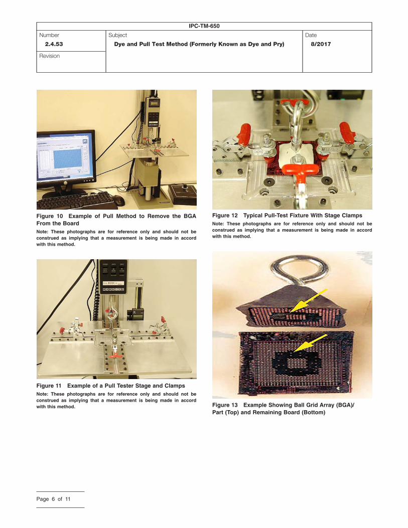
Figure 10 Example of Pull Method to Remove the BGAFrom the BoardNote: These photographs are for reference only and should not beconstrued as implying that a measurement is being made in accordwith this method.
Figure 11 Example of a Pull Tester Stage and ClampsNote: These photographs are for reference only and should not beconstrued as implying that a measurement is being made in accordwith this method.
Figure 12 Typical Pull-Test Fixture With Stage ClampsNote: These photographs are for reference only and should not beconstrued as implying that a measurement is being made in accordwith this method.
Figure 13 Example Showing Ball Grid Array (BGA)/Part (Top) and Remaining Board (Bottom)
IPC-TM-650
Number
2.4.53
Subject
Dye and Pull Test Method (Formerly Known as Dye and Pry)
Date
8/2017
Revision
Page 6 of 11

Figure 14 Mirrored Dye Indication Following Pull –Board Side
Figure 15 Mirrored Dye Indication Following Pull –Part Side
Figure 16 Examples of Board Showing LaminateFractures (Pad Cratering)Note the faint (pink stain) red dye indication.
IPC-TM-650
Number
2.4.53
Subject
Dye and Pull Test Method (Formerly Known as Dye and Pry)
Date
8/2017
Revision
Page 7 of 11

Figure 17 Example of Separation Surfaces AfterComponent Removal1. Board side2. Part side
1 2
Figure 18 Examples of Head on Pillow (HoP) FailuresA. Optical; IC carrier side on top and board side on bottomB. X-ray imageC. Post dye and pull; IC carrier sideD. Post dye and pull; board side
A B
C D
IPC-2-4-53-19
Figure 19 Example of Dye and Pull Location Type1. Type 1X2. Type 2X3. Type 3X4. Type 4X5. Type 5X6. BGA substrate7. Copper pad on BGA8. BGA solder sphere9. Copper pad on board
10. Board laminate
1
25
3
6
7
9
8
10
4
IPC-TM-650
Number
2.4.53
Subject
Dye and Pull Test Method (Formerly Known as Dye and Pry)
Date
8/2017
Revision
Page 8 of 11

IPC-2-4-53-20
Figure 20 Typical Dye and Pull Separation LocationsA. Solder ballB. Metal padC. Package substrateD. BoardE. Fracture at package side intermetallic compound (IMC)/solder interfaceF. Fracture at board side IMC/solder interfaceG. Fracture at package metal/IMC interfaceH. Package pad lift/craterJ. Fracture within bulk solderK. Board pad lift/craterL. Fracture at board metal/IMC interface
A
B
C
D
E
F
G
H
J
K
LB
IPC-TM-650
Number
2.4.53
Subject
Dye and Pull Test Method (Formerly Known as Dye and Pry)
Date
8/2017
Revision
Page 9 of 11

IPC-2-4-53-21
Figure 21 Example of Dye and Pull Location Type Coverage Mapping
B
A = 0 %= 1 to 25 %= 26 to 50 %= 51 to 75 %= 76 to 100 %
BCDEC D E
1A X
X X
XBCDEFGHJKLMNOPQRTUVW
2 3 4 5 6 7 8 9 10 11 12 132B 4B 3D
3D2D
3E
3B
3B
2B
2B
14 15 16 17 18 19 20
IPC-TM-650
Number
2.4.53
Subject
Dye and Pull Test Method (Formerly Known as Dye and Pry)
Date
8/2017
Revision
Page 10 of 11
IPC-2-4-53-22
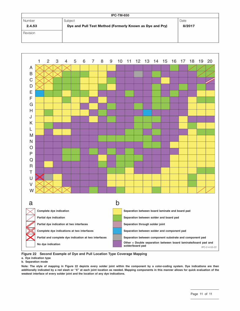
Figure 22 Second Example of Dye and Pull Location Type Coverage Mappinga. Dye indication typeb. Separation mode
Note: The style of mapping in Figure 22 depicts every solder joint within the component by a color-coding system. Dye indications are thenadditionally indicated by a red slash or “X” at each joint location as needed. Mapping components in this manner allows for quick evaluation of theweakest interface of every solder joint and the location of any dye indications.
1A
a b
BCDEFGHJKLMNOPQRTUVW
2 3 4 5 6 7 8 9 10 11 12 13 14 15 16 17 18 19 20
Complete dye indication
Partial dye indication
Partial dye indication at two interfaces
Complete dye indications at two interfaces
Partial and complete dye indication at two interfaces
No dye indication
Separation between board laminate and board pad
Separation between solder and board pad
Separation through solder joint
Separation between solder and component pad
Separation between component substrate and component pad
Other = Double separation between board laminate/board pad andsolder/board pad
IPC-TM-650
Number
2.4.53
Subject
Dye and Pull Test Method (Formerly Known as Dye and Pry)
Date
8/2017
Revision
Page 11 of 11