Embed Size (px)
Citation preview
IPHA INTERNATIONAL PRESTRESSED HOLLOWCORE ASSOCIATION
Technical Seminar, Chalmers University Gothenburg, November 6-7 2007
Design of precast concrete elements and structures according to Eurocode 2
Bo Westerberg

The Eurocode system
Overview
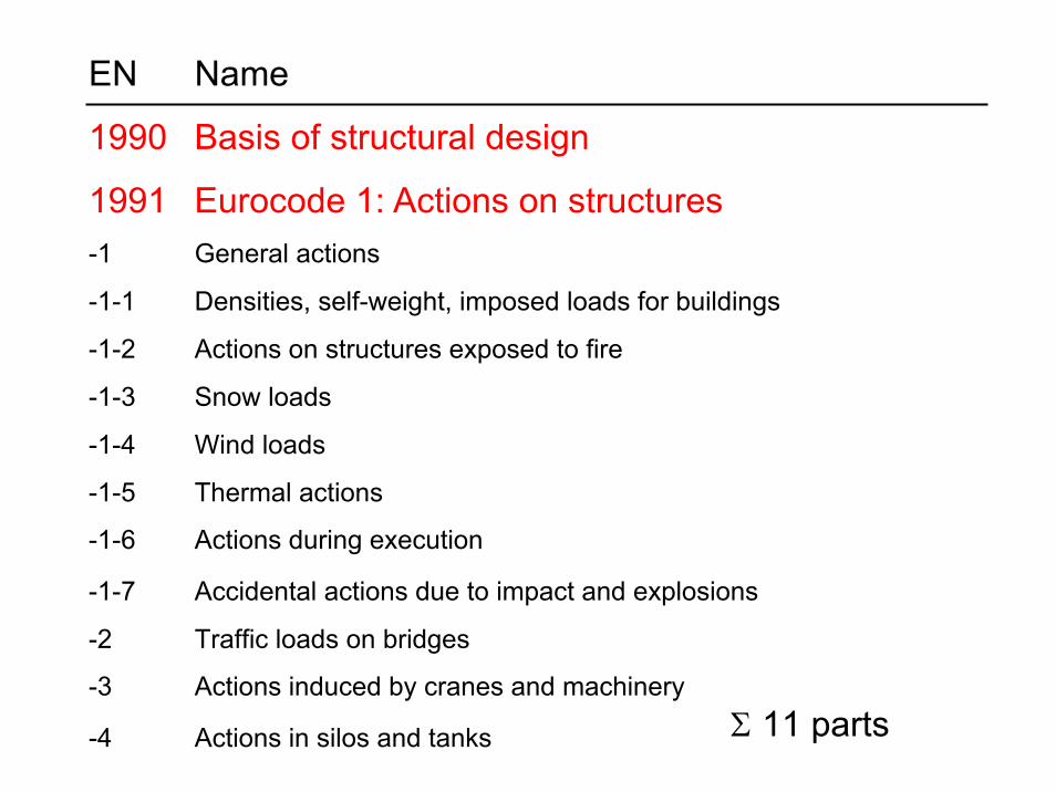
EN Name
1990 Basis of structural design
1991 Eurocode 1: Actions on structures-1 General actions
-1-1 Densities, self-weight, imposed loads for buildings
-1-2 Actions on structures exposed to fire
-1-3 Snow loads
-1-4 Wind loads
-1-5 Thermal actions
-1-6 Actions during execution
-1-7 Accidental actions due to impact and explosions
-2 Traffic loads on bridges
-3 Actions induced by cranes and machinery
-4 Actions in silos and tanks Σ 11 parts
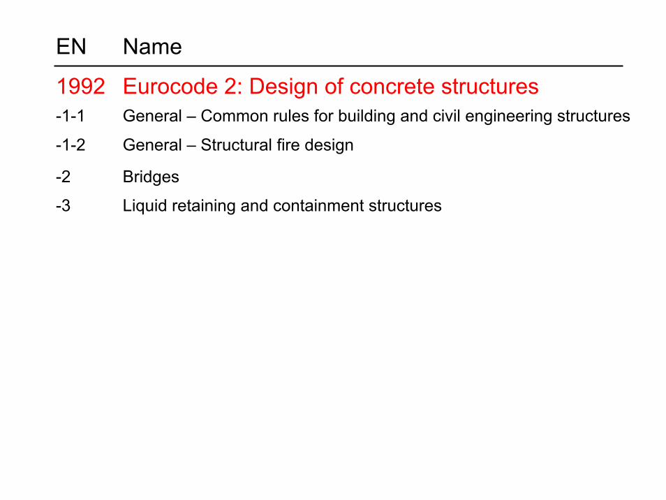
EN Name
1992 Eurocode 2: Design of concrete structures-1-1 General – Common rules for building and civil engineering structures
-1-2 General – Structural fire design
-2 Bridges
-3 Liquid retaining and containment structures
EN Name
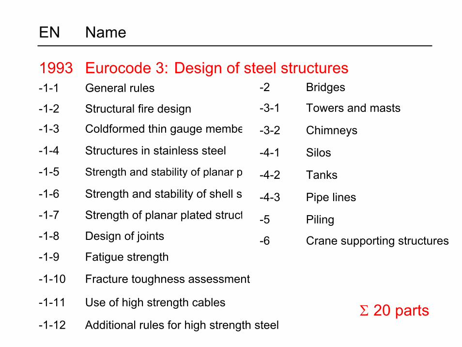
1993 Eurocode 3: Design of steel structures-1-1 General rules
-1-2 Structural fire design
-1-3 Coldformed thin gauge members and sheeting
-1-4 Structures in stainless steel
-1-5 Strength and stability of planar plated structures without transverse loading
-1-6 Strength and stability of shell structures
-1-7 Strength of planar plated structures loaded transversly
-1-8 Design of joints
-1-9 Fatigue strength
-1-10 Fracture toughness assessment
-1-11 Use of high strength cables
-1-12 Additional rules for high strength steel
-2 Bridges
-3-1 Towers and masts
-3-2 Chimneys
-4-1 Silos
-4-2 Tanks
-4-3 Pipe lines
-5 Piling
-6 Crane supporting structures
Σ 20 parts
EN Name
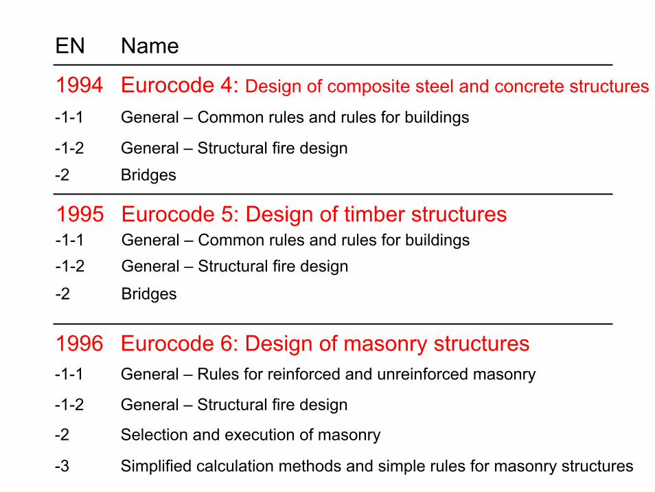
1994 Eurocode 4: Design of composite steel and concrete structures-1-1 General – Common rules and rules for buildings
-1-2 General – Structural fire design-2 Bridges
1995 Eurocode 5: Design of timber structures-1-1 General – Common rules and rules for buildings-1-2 General – Structural fire design
-2 Bridges
1996 Eurocode 6: Design of masonry structures-1-1 General – Rules for reinforced and unreinforced masonry
-1-2 General – Structural fire design
-2 Selection and execution of masonry
-3 Simplified calculation methods and simple rules for masonry structures
EN Name
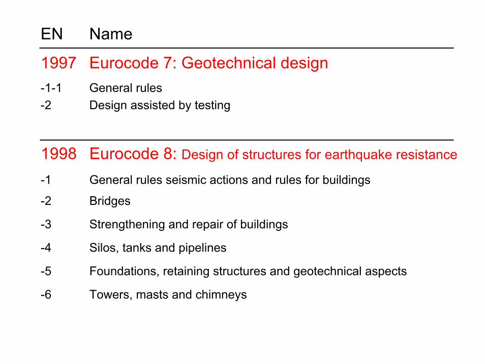
1997 Eurocode 7: Geotechnical design-1-1 General rules-2 Design assisted by testing
1998 Eurocode 8: Design of structures for earthquake resistance
-1 General rules seismic actions and rules for buildings
-2 Bridges
-3 Strengthening and repair of buildings
-4 Silos, tanks and pipelines
-5 Foundations, retaining structures and geotechnical aspects
-6 Towers, masts and chimneys
EN Name
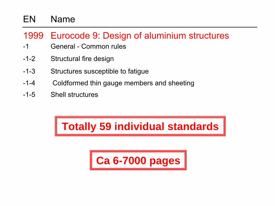
1999 Eurocode 9: Design of aluminium structures-1 General - Common rules
-1-2 Structural fire design
-1-3 Structures susceptible to fatigue
-1-4 Coldformed thin gauge members and sheeting
-1-5 Shell structures
Totally 59 individual standards
Ca 6-7000 pages
EN
199
7-1
EN
199
0
EN
199
1-1-
1
EN
199
1-1-
2
EN
199
1-1-
3
EN
199
1-1-
4
EN
199
1-1-
5
EN
199
1-1-
6
EN
199
1-1-
7
EN
199
2-1-
1
EN
199
2-1-
2
EN
199
2-2
Bas
is o
f des
ign
Sel
fwei
ght,
impo
sed
Fire
Sno
w
Win
d
Tem
pera
ture
Exe
cutio
n
Acc
iden
tal
Com
mon
ruke
s
Fire
des
ign
Brid
ges
Silo
s…
Geo
tech
nica
l
Eur
ocod
e
▼
EN
199
2-3
◄Ty
peof
stru
ctur
e
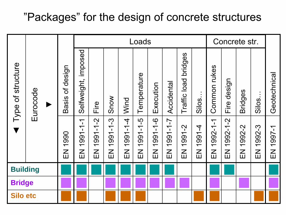
Building
Bridge
Silo etcE
N 1
991-
2Tr
affic
load
brid
ges
EN
199
1-4
Silo
s…
Loads Concrete str.
”Packages” for the design of concrete structures
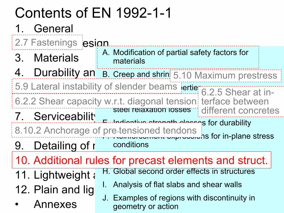
1. General2. Basis of design3. Materials4. Durability and cover to reinforcement5. Structural analysis6. Ultimate limit states7. Serviceability limit states8. Detailing of reinforcement and prestr. tendons9. Detailing of members and particular rules10. Additional rules for precast elements and struct.11. Lightweight aggregate concrete structures12. Plain and lightly reinforced concrete structures• Annexes
Contents of EN 1992-1-1
A. Modification of partial safety factors for materials
B. Creep and shrinkage strain
C. Reinforcement properties
D. Detailed calculation method for prestressingsteel relaxation losses
E. Indicative strength classes for durability
F. Reinforcement expressions for in-plane stress conditions
G. Soil structure interaction
H. Global second order effects in structures
I. Analysis of flat slabs and shear walls
J. Examples of regions with discontinuity in geometry or action
10. Additional rules for precast elements and struct.
2.7 Fastenings
5.9 Lateral instability of slender beams6.2.2 Shear capacity w.r.t. diagonal tension
6.2.5 Shear at in-terface betweendifferent concretes
8.10.2 Anchorage of pre-tensioned tendons
5.10 Maximum prestress
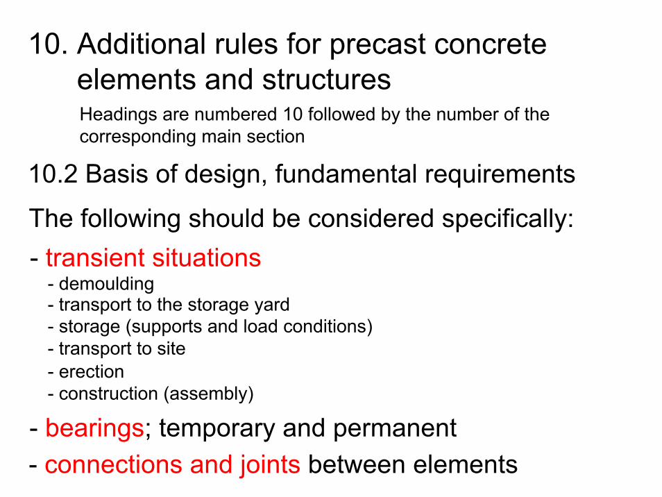
10. Additional rules for precast concreteelements and structuresHeadings are numbered 10 followed by the number of the corresponding main section
10.2 Basis of design, fundamental requirements
The following should be considered specifically:- transient situations
- demoulding- transport to the storage yard- storage (supports and load conditions)- transport to site
- bearings; temporary and permanent- connections and joints between elements
- erection- construction (assembly)
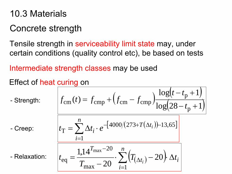
Concrete strength
Intermediate strength classes may be used
- Strength:
- Creep:
- Relaxation:
( )
10.3 Materials
( )( )128log
1log)(
p
pcmpcmcmpcm +−
+−−+=
ttt
ffftf
Tensile strength in serviceability limit state may, under certain conditions (quality control etc), be based on tests
Effect of heat curing on
( )( )∑=
Δ
−Δ⋅−⋅
−=
n
iit
TtT
Tt
i1max
20
eq 2020
14,1 max
( )( )[ ]∑=
−Δ+−⋅Δ=n
i
tTi
iett1
65,132734000T
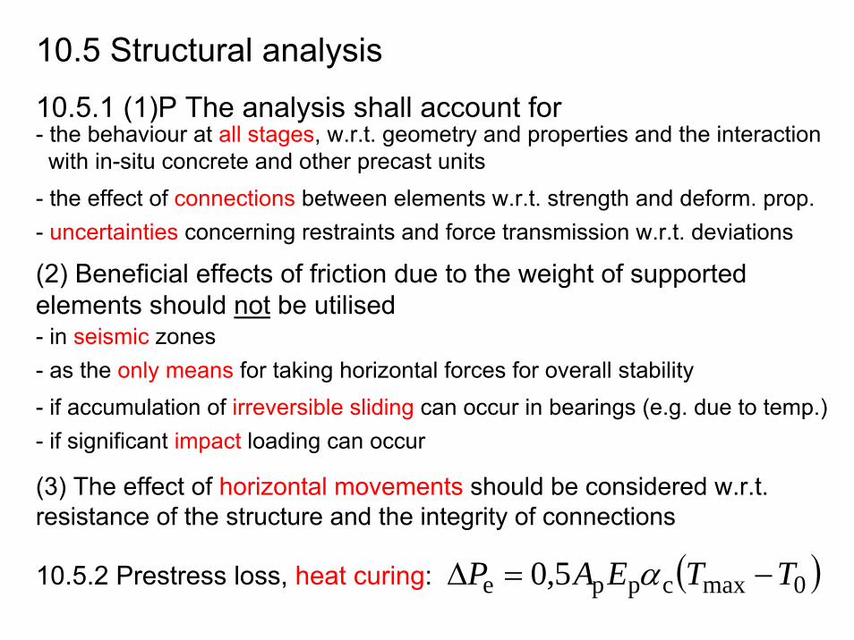
10.5 Structural analysis
10.5.1 (1)P The analysis shall account for- the behaviour at all stages, w.r.t. geometry and properties and the interaction with in-situ concrete and other precast units
- the effect of connections between elements w.r.t. strength and deform. prop.- uncertainties concerning restraints and force transmission w.r.t. deviations
(2) Beneficial effects of friction due to the weight of supportedelements should not be utilised- in seismic zones- as the only means for taking horizontal forces for overall stability- if accumulation of irreversible sliding can occur in bearings (e.g. due to temp.)- if significant impact loading can occur
(3) The effect of horizontal movements should be considered w.r.t. resistance of the structure and the integrity of connections
10.5.2 Prestress loss, heat curing: ( )0maxcppe 5,0 TTEAP −=Δ α
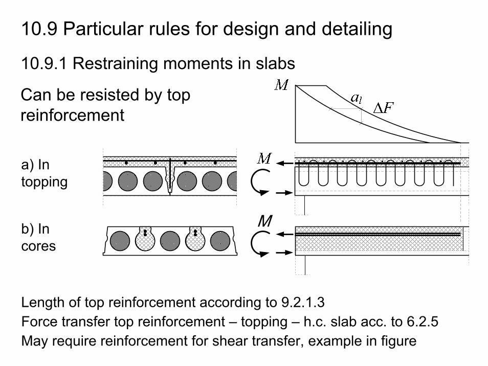
May require reinforcement for shear transfer, example in figure
10.9.1 Restraining moments in slabs
a) In topping
b) In cores
Can be resisted by topreinforcement
Force transfer top reinforcement – topping – h.c. slab acc. to 6.2.5Length of top reinforcement according to 9.2.1.3
10.9 Particular rules for design and detailing
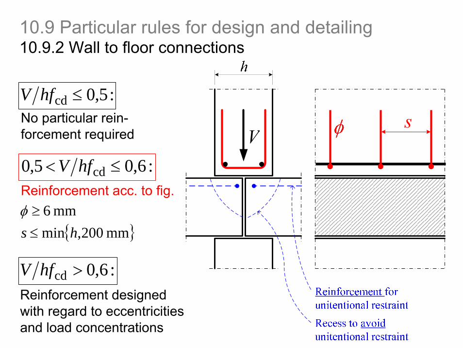
10.9.2 Wall to floor connections
: 5,0cd ≤hfVNo particular rein-forcement required
: 6,05,0 cd ≤< hfVReinforcement acc. to fig.
{ }mm 200,minmm 6
hs ≤≥φ
: 6,0cd >hfVReinforcement designedwith regard to eccentricitiesand load concentrations
10.9 Particular rules for design and detailing
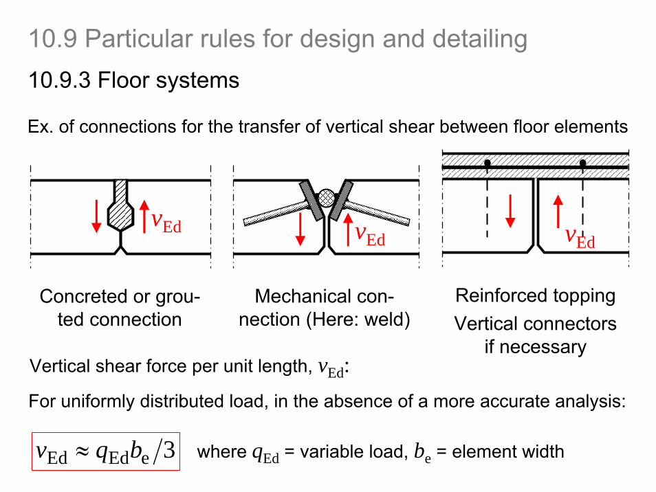
10.9.3 Floor systems
Ex. of connections for the transfer of vertical shear between floor elements
Concreted or grou-ted connection
Mechanical con-nection (Here: weld)
Reinforced toppingVertical connectors
if necessaryVertical shear force per unit length, vEd:
3eEdEd bqv ≈ where qEd = variable load, be = element width
vEd vEd vEd
For uniformly distributed load, in the absence of a more accurate analysis:
10.9 Particular rules for design and detailing
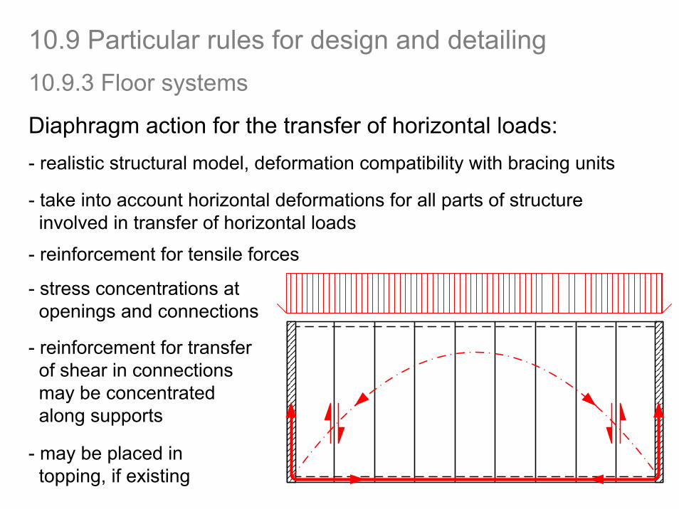
Diaphragm action for the transfer of horizontal loads:- realistic structural model, deformation compatibility with bracing units
10.9.3 Floor systems
10.9 Particular rules for design and detailing
- take into account horizontal deformations for all parts of structureinvolved in transfer of horizontal loads
- reinforcement for tensile forces
- stress concentrations at openings and connections
- reinforcement for transfer of shear in connectionsmay be concentratedalong supports
- may be placed in topping, if existing
Elements with a topping of at least 40 mm may be designedas composite members; interface shear according to 6.2.5
Transverse reinforcement for bending and other effects maylie entirely in the topping
Webs or ribs in isolated slab units (= units not connected for shear transfer): minimum shear reinforcement as for beams
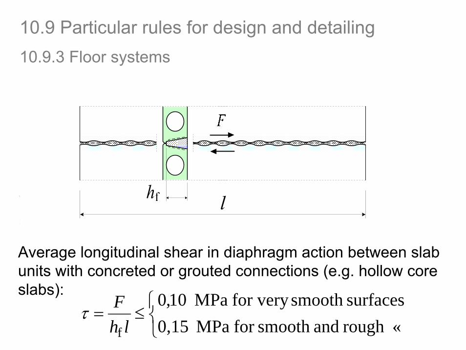
Average longitudinal shear in diaphragm action between slabunits with concreted or grouted connections (e.g. hollow coreslabs):
10.9.3 Floor systems
10.9 Particular rules for design and detailing
⎩⎨⎧
≤=«rough andsmooth for MPa 0,15
surfacessmooth for very MPa 10,0
f lhFτ
10.9.4 Connections and supports for precast elements
10.9 Particular rules for design and detailing
Materials used for connections shall be:- stable and durable for the design working life of the structure- chemically and physically compatible- protected against adverse chemical and physical influences- fire resistant to match the fire resistance of the structure
Supporting pads shall have strength and deformation propertiesaccording to design assumptions
Metal fastenings for cladding shall be of corrosion resistantmaterial or coated (unless in X0 or XC1 or protected)
Before welding, annealing or cold forming: suitability of material shall be verified
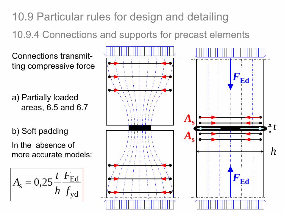
Connections transmit-ting compressive force
a) Partially loadedareas, 6.5 and 6.7
b) Soft padding
yd
Eds 25,0
fF
htA =
FEd
As
As
FEd
h
t
10.9.4 Connections and supports for precast elements
10.9 Particular rules for design and detailing
In the absence of more accurate models:
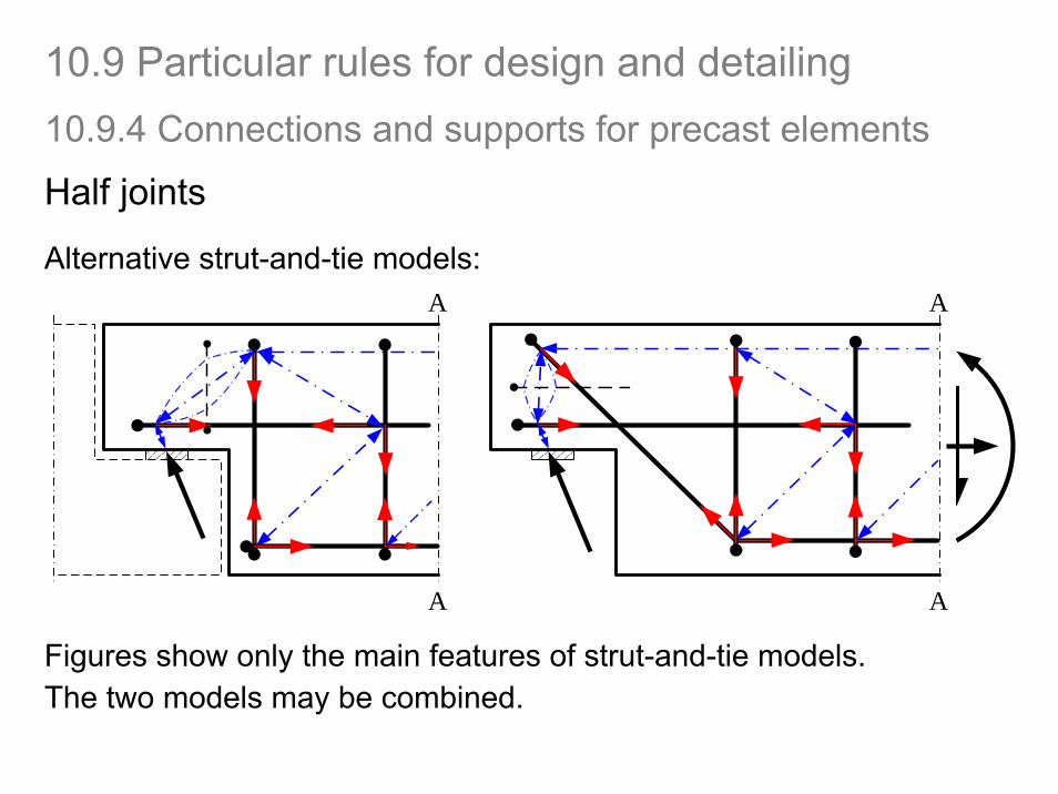
Half joints
Alternative strut-and-tie models:
Figures show only the main features of strut-and-tie models. The two models may be combined.
A
A
A
A
10.9.4 Connections and supports for precast elements
10.9 Particular rules for design and detailing
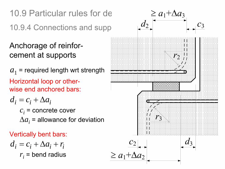
a1 = required length wrt strength
Δai = allowance for deviation
10.9.4 Connections and supports for precast elements
10.9 Particular rules for design and detailing
Anchorage of reinfor-cement at supports
ci = concrete coveriii acd Δ+=
iiii racd +Δ+=
Horizontal loop or other-wise end anchored bars:
Vertically bent bars:
ri = bend radius
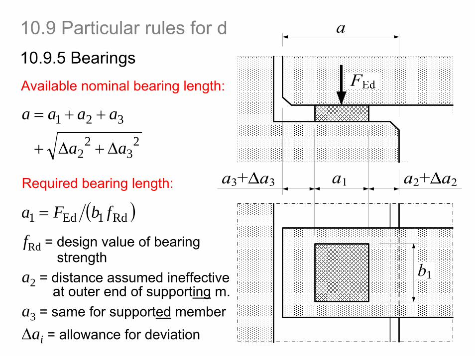
10.9.5 Bearings
10.9 Particular rules for design and detailing
23
22
321
aa
aaaa
Δ+Δ+
++=
Available nominal bearing length:
( )Rd1Ed1 fbFa =
Required bearing length:
fRd = design value of bearingstrength
a2 = distance assumed ineffectiveat outer end of supporting m.
a3 = same for supported memberΔai = allowance for deviation
1
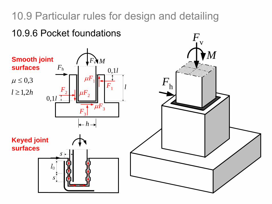
10.9.6 Pocket foundations
F1F2
F3
Fv
M
Fh
FvFh
M0,1l
0,1l
lμF1
μF2
μF3
Smooth joint surfaces
Keyed joint surfaces
3,0≤μhl 2,1≥
h
10.9 Particular rules for design and detailing
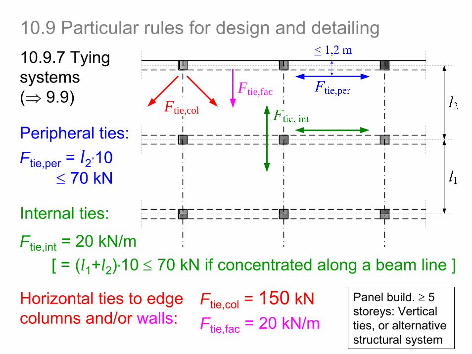
10.9.7 Tyingsystems(⇒ 9.9)
10.9 Particular rules for design and detailing
Peripheral ties:Ftie,per = l2*10
≤ 70 kN
Internal ties:
Ftie,int = 20 kN/m
Horizontal ties to edgecolumns and/or walls:
Ftie,col
Ftie,fac
Ftie,col = 150 kNFtie,fac = 20 kN/m
Panel build. ≥ 5 storeys: Verticalties, or alternative structural system
[ = (l1+l2)*10 ≤ 70 kN if concentrated along a beam line ]
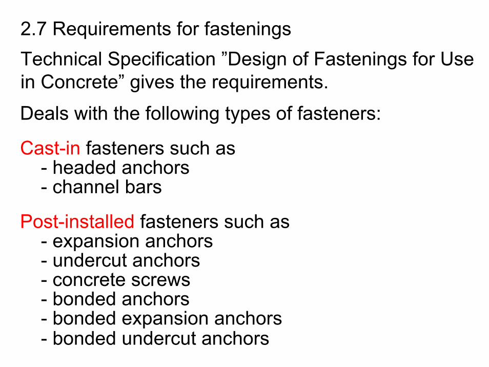
2.7 Requirements for fasteningsTechnical Specification ”Design of Fastenings for Usein Concrete” gives the requirements. Deals with the following types of fasteners:
Cast-in fasteners such as- headed anchors- channel bars
Post-installed fasteners such as- expansion anchors- undercut anchors- concrete screws- bonded anchors- bonded expansion anchors- bonded undercut anchors
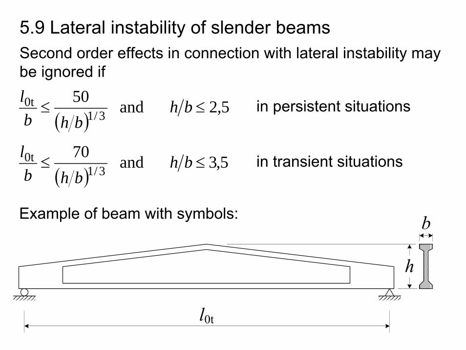
5.9 Lateral instability of slender beams
( )5,2and50
3/10t ≤≤ bh
bhbl in persistent situations
( )5,3and70
3/10t ≤≤ bh
bhbl in transient situations
Example of beam with symbols:
Second order effects in connection with lateral instability maybe ignored if
⎪⎩
⎪⎨⎧
=
=
p0,1k
pkmaxp,
maxp,pmax
9,0
8,0
f
f
AP
σ
σ
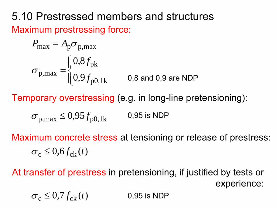
5.10 Prestressed members and structuresMaximum prestressing force:
0,8 and 0,9 are NDP
Temporary overstressing (e.g. in long-line pretensioning):
p0,1kmaxp, 95,0 f≤σ 0,95 is NDP
Maximum concrete stress at tensioning or release of prestress:)(6,0 ckc tf≤σ
At transfer of prestress in pretensioning, if justified by tests or experience:
)(7,0 ckc tf≤σ 0,95 is NDP
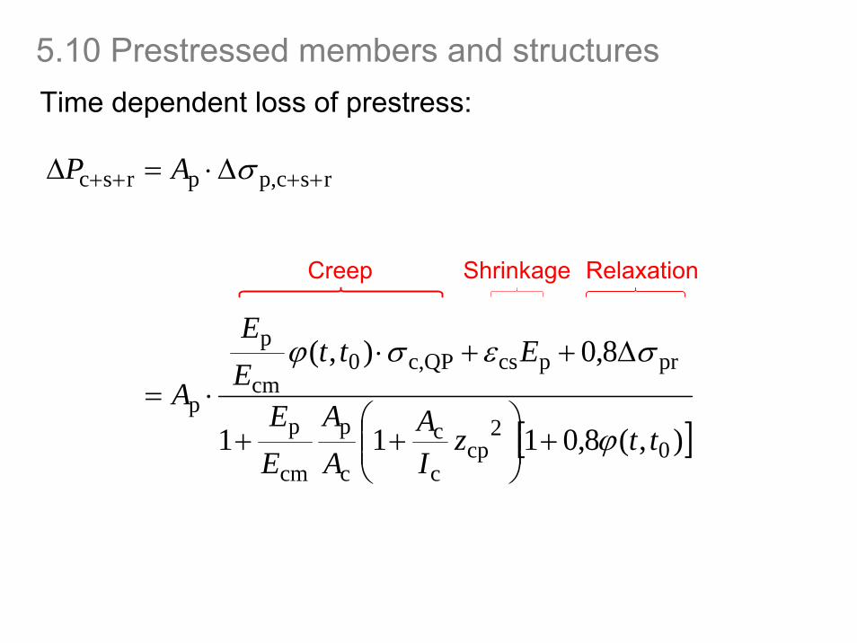
5.10 Prestressed members and structuresTime dependent loss of prestress:
rscp,prsc ++++ Δ⋅=Δ σAP
Creep Shrinkage Relaxation
[ ]),(8,0111
8,0),(
02
cpc
c
c
p
cm
p
prpcsQPc,0cm
p
p
ttzIA
AA
EE
EttEE
Aϕ
σεσϕ
+⎟⎟⎠
⎞⎜⎜⎝
⎛++
Δ++⋅⋅=
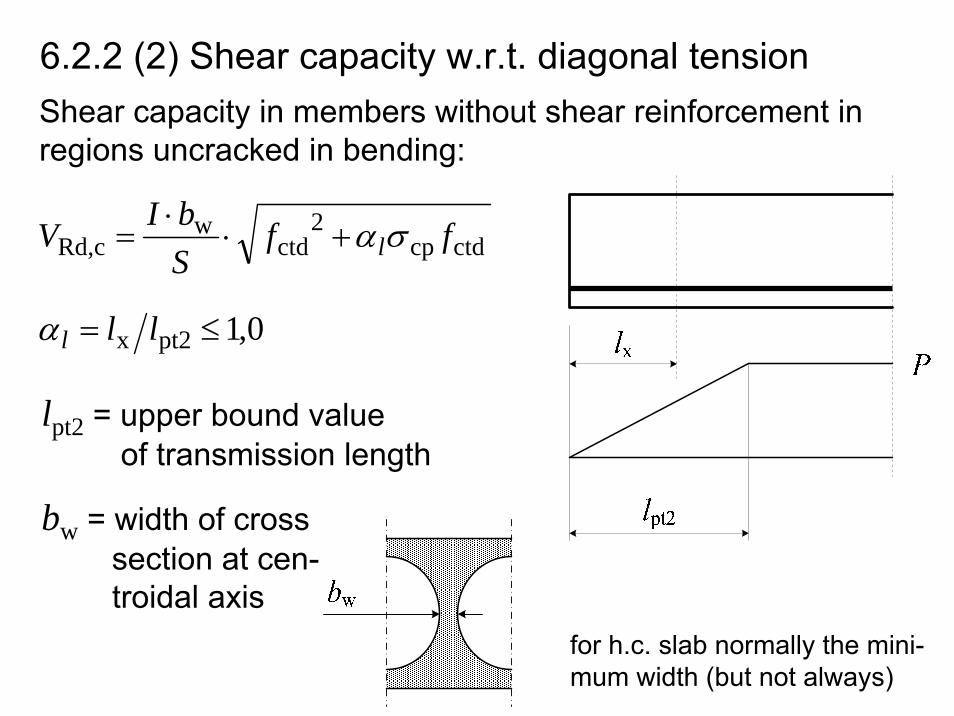
6.2.2 (2) Shear capacity w.r.t. diagonal tensionShear capacity in members without shear reinforcement in regions uncracked in bending:
ctdcp2
ctdw
cRd, ffSbIV lσα+⋅⋅
=
0,1pt2x ≤= lllα
lpt2 = upper bound valueof transmission length
bw = width of cross section at cen-troidal axis
for h.c. slab normally the mini-mum width (but not always)
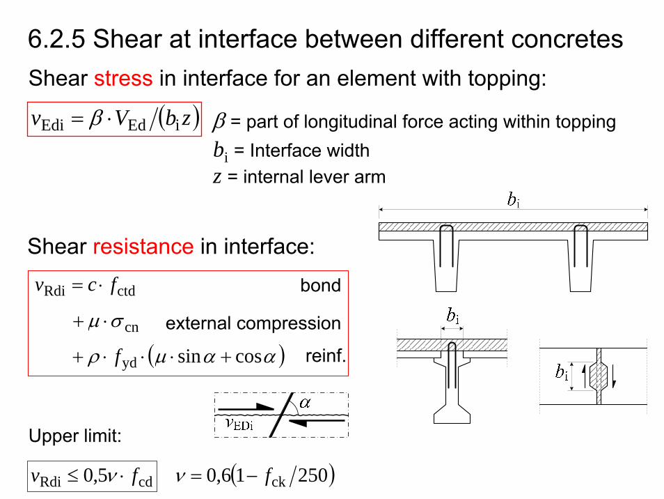
Shear stress in interface for an element with topping:
ctdRdi fcv ⋅=
( )zbVv iEdEdi ⋅= β β = part of longitudinal force acting within toppingbi = Interface width
Shear resistance in interface:
cnσμ ⋅+
( )ααμρ cossinyd +⋅⋅⋅+ f
cdRdi 5,0 fv ⋅≤ ν
bond
external compression
reinf.
Upper limit:
6.2.5 Shear at interface between different concretes
z = internal lever arm
( )25016,0 ckf−=ν
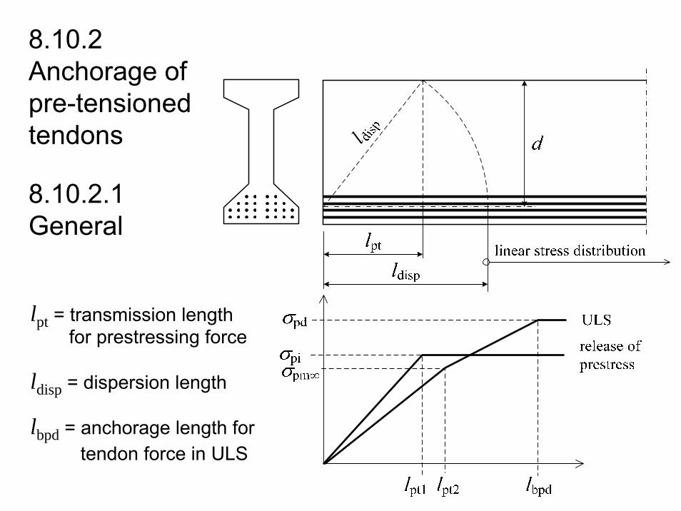
lpt = transmission lengthfor prestressing force
ldisp = dispersion length
lbpd = anchorage length for tendon force in ULS
8.10.2 Anchorage of pre-tensionedtendons
8.10.2.1 General
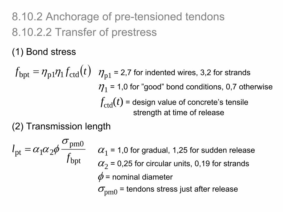
(1) Bond stress
( )tff ctd1p1bpt ηη= ηp1 = 2,7 for indented wires, 3,2 for strands
η1 = 1,0 for ”good” bond conditions, 0,7 otherwise
fctd(t) = design value of concrete’s tensilestrength at time of release
(2) Transmission length
bpt
pm021pt f
lσ
φαα=α2 = 0,25 for circular units, 0,19 for strands
φ = nominal diameterσpm0 = tendons stress just after release
α1 = 1,0 for gradual, 1,25 for sudden release
8.10.2 Anchorage of pre-tensioned tendons8.10.2.2 Transfer of prestress
8.10.2.2 Transfer of prestress8.10.2 Anchorage of pre-tensioned tendons
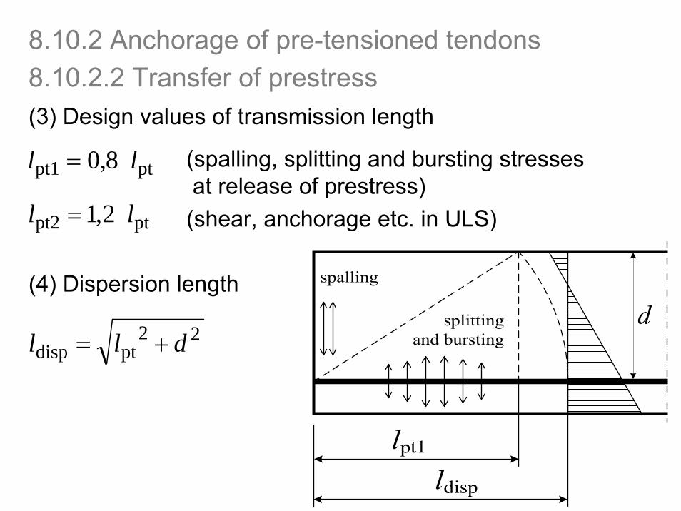
(3) Design values of transmission length
ptpt2 2,1 ll =
(4) Dispersion length
22ptdisp dll +=
ptpt1 8,0 ll = (spalling, splitting and bursting stressesat release of prestress)(shear, anchorage etc. in ULS)
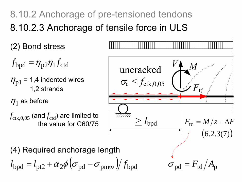
ctd1p2bpd ff ηη=
ηp1 = 1,4 indented wires1,2 strands
η1 as before
( ) bpdpmpd2pt2bpd fll ∞−+= σσφα
(2) Bond stress
(4) Required anchorage length
fctk,0,05 (and fctd) are limited to the value for C60/75
( )6.2.3(7) td FzMF Δ+=
ptdpd AF=σ
8.10.2.3 Anchorage of tensile force in ULS8.10.2 Anchorage of pre-tensioned tendons
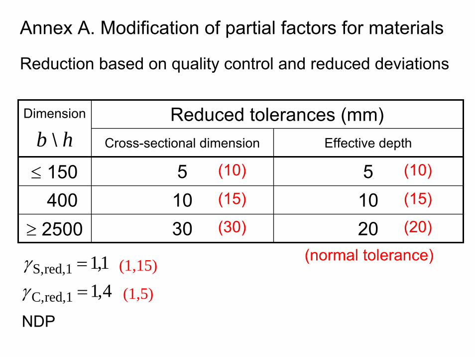
Annex A. Modification of partial factors for materials
Reduction based on quality control and reduced deviations
Reduced tolerances (mm)Dimension
b \ h Cross-sectional dimension Effective depth
≤ 150 5 5400 10 10
≥ 2500 30 20
(10)
(15)
(30)
(10)
(15)
(20)
(normal tolerance)1,1red,1S, =γ4,1red,1C, =γ
(1,15)
(1,5)
NDP
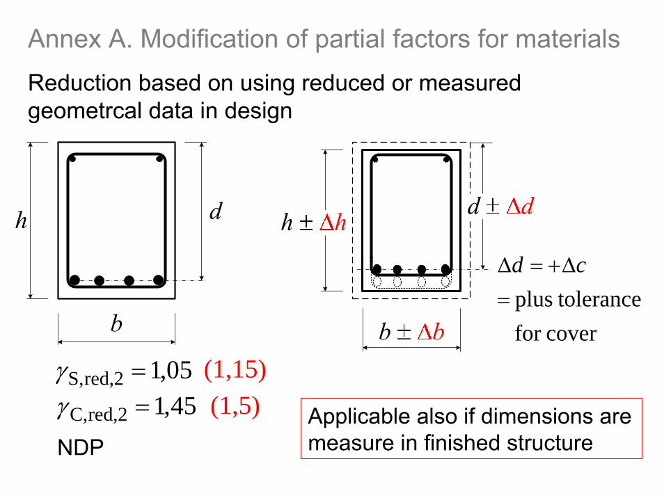
Reduction based on using reduced or measuredgeometrcal data in design
coverfor toleranceplus =
Δ+=Δ cd
05,1red,2S, =γ45,1red,2C, =γ
(1,15)(1,5)
NDPApplicable also if dimensions are measure in finished structure
Annex A. Modification of partial factors for materials
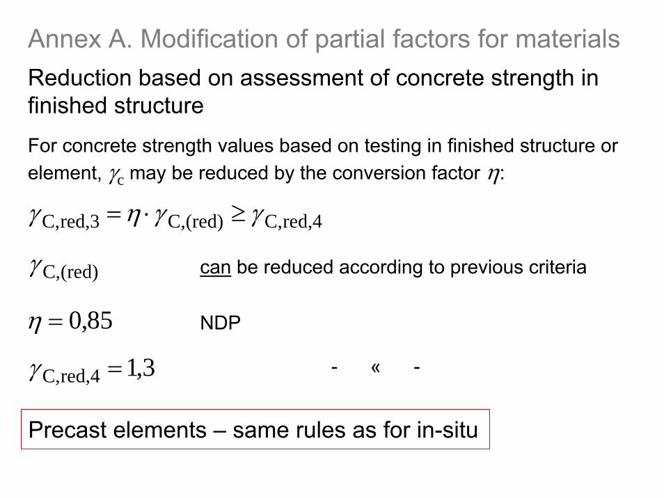
Reduction based on assessment of concrete strength in finished structure
red,4C,(red)C,red,3C, γγηγ ≥⋅=
For concrete strength values based on testing in finished structure or element, γc may be reduced by the conversion factor η:
85,0=η NDP
3,1red,4C, =γ - « -
(red)C,γ can be reduced according to previous criteria
Precast elements – same rules as for in-situ
Annex A. Modification of partial factors for materials


![EN 1993-1-1: Eurocode 3: Design of steel structures - Part ... · PDF fileEN 1996 Eurocode 6: Design of masonry structures EN ]997 Eurocode 7: Geotechnical design EN 1998 Eurocode](https://img.pdfslide.net/doc/110x75/5a71061f7f8b9aa2538c9518/en-1993-1-1-eurocode-3-design-of-steel-structures-part-nbsppdf.jpg)