Embed Size (px)
Citation preview

"This machine is approved by the EPA for E10 (10% ethanol) and lower fuel only. Do not use any fuel >E10 in this machine."
Illustrated Parts List
532 44 05-64 Rev. 1
YTH2042
07002

27
TRACTOR - - MODEL NUMBER YTH2042 (96048000300), PRODUCT NO. 960 48 00-03SCHEMATIC
MFUSE
STARTERSOLENOIDBATTERY
CLUTCH/BRAKE(PEDAL UP)
REVERSE SWITCH(NOT IN REVERSE)
SEAT SWITCH(NOT OCCUPIED)
SHORTINGCONNECTOR
CHASSISHARNESS
IGNITIONUNIT
HOURMETER
CHASSIS HARNESSCONNECTOR
(MATING SIDE)
DASH HARNESSCONNECTOR
(MATING SIDE)
FUELLINE
FUEL SHUT-OFFSOLENOID
(IF SO EQUIPPED)
JUNCTIONCONNECTOR
SMB
GL
2
3
1
6
A2A1
M
63
52
41
6
5
4
3
2
1
SPARKPLUGS GAP
(2 PLUGS ONTWIN CYL. ENGINES)(OPTIONAL)
NON-REMOVABLECONNECTIONS
REMOVABLECONNECTIONS
WIRING INSULATED CLIPSNOTE: IF WIRING INSULATEDCLIPS WERE REMOVED FORSERVICING OF UNIT, THEYSHOULD BE RE-INSTALLED TOPROPERLY SECURE YOURWIRING.
SCH11
IGNITION SWITCHCIRCUITPOSITION
OFFB+A1RUN/OVERRIDE
B + S + A1START
M+G+A1
B+A1RUN
“MAKE”
L+A2
ATTACHMENT CLUTCH(CLUTCH OFF)
BLAC
K
BLAC
K/W
HIT
E
BLUE
BLUE BLACK
BLACKBLACK
BLACK
BLACK
BLACK
BLACK
BLACK
DERRED
WHITEWHITE
GRAY
GRAY
BLACK
BLACK
POWER OUTLET(OPTIONAL)
12V
BLACK
A
AMMETER(OPTIONAL)
RED
BLACKBROWN
HEADLIGHTS
LIGHT SWITCHORANGE
LIGHTING SYSTEM OUTPUT5 AMP AC @ 3600 RPM ALTERNATOR
14 VOLTS AC MIN. @ 3600 RPM (LIGHTS OFF)
DIODE
28 VOLTS AC MIN. @ 3600 RPM(CHARGING SYSTEM DISCONNECTED)
CHARGING SYSTEM OUTPUT3 AMP DC @ 3600 RPM
NOTEYOUR TRACTOR ISEQUIPPED WITH A SPECIALALTERNATOR SYSTEM.THE LIGHTS ARE NOTCONNECTED TO THEBATTERY, BUT HAVE THEIROWN ELECTRICAL SOURCE.BECAUSE OF THIS, THEBRIGHTNESS OF THE LIGHTSWILL CHANGE WITH ENGINESPEED. AT IDLE THE LIGHTSWILL DIM. AS THE ENGINE ISSPEEDED UP, THE LIGHTSWILL BECOME THEIRBRIGHTEST.

28
TRACTOR - - MODEL NUMBER YTH2042 (96048000300), PRODUCT NO. 960 48 00-03ELECTRICAL
3033
34
22
79 21
41
42
26
4327
40
71
16
87
25
T06S
90
28 55
With 12V Outlet Option
59
103
With Service Minder Option
4646
102
29
2
105

29
TRACTOR - - MODEL NUMBER YTH2042 (96048000300), PRODUCT NO. 960 48 00-03ELECTRICAL
KEY PARTNO. NO. DESCRIPTION
1 532 16 34-65 Battery2 874 76 04-12 Bolt Hex Head 1/4-20 x 3/48 532 19 32-28 Box Battery16 532 17 61-38 Switch Interlock Push-In21 532 40 02-52 Harness Socket Light w/4152J22 532 00 41-52 Bulb Light25 532 41 28-95 Cable Starter26 532 17 51-58 Fuse27 873 51 04-00 Nut Keps Hex 1/4-20 unc28 532 19 88-85 Cable, Ground29 532 40 15-45 Switch, Seat 30 532 19 33-50 Switch, Ign33 532 41 19-35 Key/Chain34 532 11 07-12 Switch Light/Reset40 532 40 10-98 Harness Ign. Dash41 817 72 04-08 Screw Thd Cut 1/4-20 x 1/242 532 13 15-63 Cover, Terminal43 532 19 25-07 Solenoid46 532 40 17-63 Gauge Serviceminder Hrmtr55 817 06 05-12 Screw Thdrol 5/16-18 x 3/4 TYTT71 532 40 04-49 Harness Ign.79 532 17 52-42 Socket Asm. Bulb87 532 19 78-02 Switch Interlock90 532 43 53-95 Cover Terminal102 532 40 44-54 Harness Pigtail105 532 40 75-68 Switch Reverse
NOTE: All component dimensions given in U.S. inches 1 inch = 25.4 mm

30
TRACTOR - - MODEL NUMBER YTH2042 (96048000300), PRODUCT NO. 960 48 00-03CHASSIS
182
68
68
176176
175178
228
228
183
194
236
150
180
68
68
213
52
218
34130
130
177
chassis-tex_GT HUSQ_II_28 189
189
152
217
235
195
176
5
176
176
37
194
194
181
181
36
36
162
287
138
137
137
159
159
196 198
199
14
130
130
130
202
203
208
1815
25
207
205151
206
3
214
204
130
297
191

31
TRACTOR - - MODEL NUMBER YTH2042 (96048000300), PRODUCT NO. 960 48 00-03CHASSIS
KEY PART NO. NO. DESCRIPTION
3 532 43 97-52 Logo5 532 43 74-73 Dash14 532 44 11-77 Hood15 532 43 97-33 Lens LH18 532 43 77-62 Grille25 532 43 97-32 Lens RH34 532 19 61-25 Plate Engine36 817 06 05-12 Screw 5/16-18 x 3/437 532 44 12-06 Fender52 873 68 05-00 Nut Lock 5/16-1868 817 49 05-08 Screw Thdrol 5/16-18 x 1/2130 532 41 63-58 Screw #10 x 0.750137 532 40 75-90 Bumper Dash138 532 40 29-54 Cupholder150 532 43 97-74 Air Duct152 532 19 95-35 Shield Browning159 817 00 06-12 Screw Hexwsh Thrd 3/8-16 x 3/4162 532 14 24-32 Screw175 532 19 63-04 Crossmember176 532 40 07-76 Screw 10-24 x 5/8177 532 19 52-27 Bushing Steering178 532 19 97-82 Cargo Asm. Net180 532 19 54-57 Chassis181 532 40 30-25 Bushing Mtg. Fender Crgo182 532 40 68-59 Dash Lower183 874 52 05-20 Bolt Fin Hex 5/16-18 x 1-1/4
NOTE: All component dimensions given in U.S. inches 1 inch = 25.4 mm
189 817 00 05-12 Screw 5/16-18 x 3/4191 532 43 74-55 Insert Reflective RH194 873 90 05-00 Nut Lock Hex Flange 5/16-18195 532 40 41-37 Plug Hole Dash Lower196 532 41 91-96 Console Asm. Deck Lift198 532 42 58-86 Indicator Deck Lift199 532 41 34-85 Plate Deck Lift202 532 43 97-28 Vent Side Hood RH203 532 43 97-27 Vent Side Hood LH204 532 43 57-14 Vent Top Hood205 532 43 97-30 Skirt Hood Side RH206 532 43 97-29 Skirt Hood Side LH207 532 43 97-34 Bezel RH208 532 43 97-35 Bezel LH213 874 76 05-12 Bolt 5/16-18 x 3/4214 532 19 91-45 Clip Retainer Tinner217 532 40 91-67 Rod Pivot218 532 19 63-95 X-Piece Hood Stop228 532 19 51-61 Stud Fastner235 532 40 61-29 Spacer Fender236 873 93 05-00 Nut Lock 5/16-18 unc287 817 60 04-06 Screw 1/4-20 x 3/8297 532 43 74-56 Insert Reflective LH
KEY PART NO. NO. DESCRIPTION

32
TRACTOR - - MODEL NUMBER YTH2042 (96048000300), PRODUCT NO. 960 48 00-03DRIVE
52
51
170
171
225
125
drive-tex_K46_pedal_81
2
2
73
73 33
2051
116
33
230
230
183
183
205
116
56
213
221
160
206
26
207
209
92 125
116
64
188
161
35
184
167
160
42
29
15
159
159
221
186
189
49
187
50
5152
51
190
185
125
226
227
125
80125
208210
214125
215
153
166
211
211
222
17
163
153
99
216
143

33
TRACTOR - - MODEL NUMBER YTH2042 (96048000300), PRODUCT NO. 960 48 00-03DRIVE
NOTE: All component dimensions given in U.S. inches 1 inch = 25.4 mm
1 - - - - - - - - - Transaxle, Tufftorq K46BT2 532 12 35-83 Key Square15 819 13 13-16 Washer 13/32 x 13/16 x 16 Ga.17 532 41 36-78 Spring, Brake26 532 19 96-79 Spring Return Cruise29 532 40 38-06 Rod, Brake33 812 00 00-01 Ring E 35 532 43 54-86 Rod, Brake, Park42 532 12 48-72 Cover, Foot Pedal49 872 11 06-14 Bolt50 532 19 43-27 Pulley Idler Flat51 873 90 06-00 Lock Nut 3/8-1652 532 19 43-26 Idler V-Groove 910" Offset56 532 13 09-69 V-Belt, Drive64 532 19 78-65 Shaft Asm. Pedal Brake Control73 874 49 05-40 Bolt Hex 5/16-18 x 2 1/2 Gr. 580 532 41 00-24 Strap Torque92 874 76 05-20 Bolt Fin Hex 5/16-18 unc x 1.2599 532 41 57-42 Rod Spring Bypass116 873 90 05-00 Nut Lock Hex Flange 5/16-18125 817 00 05-12 Screw 5/16-18 x 3/4143 817 49 05-08 Screw 5/16-18 x 1/2153 532 12 47-88 Retainer Spring 1"159 876 02 04-12 Pin Cotter 1/8 x 3/4160 532 16 94-84 Retainer Clip161 532 10 57-09 Spring, Return, Clutch163 532 40 10-34 Rod Control166 532 42 91-64 Nut Push167 532 40 52-57 Latch Brake Parking170 532 19 43-22 Keeper V-Idler183 532 13 70-57 Spacer Axle
KEY PARTNO. NO. DESCRIPTION
KEY PARTNO. NO. DESCRIPTION
184 532 40 31-18 Handle Parking Brake185 872 11 06-22 Bolt186 532 19 43-21 Spacer Retainer187 819 13 32-10 Washer188 532 19 43-23 Link Clutch Ground Drive189 532 19 43-17 Bellcrank Ground Drive190 532 19 43-18 Keeper Bellcrank Ground Drive205 532 12 17-48 Washer 25/32 x 1-5/8 x 16 Ga.206 532 19 78-67 Bracket Mount Latch Cruise207 532 19 78-68 Latch Control Cruise208 532 19 78-69 Gear Sector Control Cruise209 532 19 95-92 Rod Control Cruise210 532 40 09-80 Rocker Asm. Pedal Control211 532 12 01-83 Bearing Nylon213 532 40 31-19 Knob Control Cruise214 532 42 12-63 Pedal Forward Pad215 532 40 17-23 Pedal Reverse216 532 19 61-31 Bracket Pulley Idler221 532 40 31-87 Retainer Spring Clip Handle222 879 21 20-10 Washer 21/32 x 1-1/4 10 Ga.225 532 40 33-19 Keeper Belt Transaxle226 532 40 15-64 Bracket Mount Torque227 817 49 05-12 Screw 5/16-18 x 3/4230 532 18 89-67 Washer Harden .793 x 1.637 x 060

34
1
84
29
SPARK ARRESTER KIT
84
45
21
2062
71
70
79
69
2
9
12
42
85
8281
TRACTOR - - MODEL NUMBER YTH2042 (96048000300), PRODUCT NO. 960 48 00-03ENGINE

35
TRACTOR - - MODEL NUMBER YTH2042 (96048000300), PRODUCT NO. 960 48 00-03ENGINE
KEY PART NO. NO. DESCRIPTION
NOTE: All component dimensions given in U.S. inches. 1 inch = 25.4 mm
For engine service and replacement parts, call the toll free number for your engine manufacturer listed below:
Briggs & Stratton 1-800-233-3723
1 - - - - - - Engine B8S Model No. 406777-1518-B12 532 14 97-23 Muffler9 532 19 43-20 Keeper Belt Engine12 532 40 54-71 Pulley Engine15 532 40 74-89 Tank Fuel 18 532 43 02-20 Cap Fuel20 532 42 35-02 Control Throttle/Choke21 532 41 63-58 Screw #10 x 0.750 BOS Thread28 532 40 11-37 Fuel Line29 532 13 71-80 Spark Arrester Kit37 532 12 34-87 Clamp Hose42 810 04 07-00 Washer Lock 7/1645 873 51 04-00 Nut Keps Hex 1/4-20 unc62 532 43 40-17 Shield Heat Muffler69 532 16 53-91 Gasket70 532 15 99-55 Exhaust Tube LH71 532 16 05-89 Exhaust Tube RH79 532 18 39-06 Screw Socket HD 5/16-18 x 181 532 14 84-56 Tube Drain Oil Easy82 532 42 82-87 Valve Drain Oil84 817 06 06-20 Screw 3/8-16 x 1-1/485 532 17 39-37 Bolt 7/16-20 x 4 x Gr. 5-1.587 532 17 18-77 Bolt 5/16-18 unc x 3/490 817 00 06-16 Screw 3/8-16 x 196 819 09 14-16 Washer 9/32 x 7/8 x 16 Ga.97 817 67 04-12 Screw 1/4-20 x 3/4
Engine Power Rating Information
The gross power rating for individual gas engine models is labeled in accordance with SAE (Society of Automotive Engineers) code J1940 (Small Engine Power & Torque Rating Procedure), and rating performance has been obtained and corrected in accordance with SAE J1995 (Revision 2002-05). Torque values are derived at 3060 RPM; horsepower values are derived at 3600 RPM. Actual gross engine power will be lower and is affected by, among other things, ambi-ent operating conditions and engine-to-engine variability. Given both the wide array of products on which engines are placed and the variety of environmental issues applicable to operating the equipment, the gas engine will not develop the rated gross power when used in a given piece of power equipment (actual “on-site” or net power). This difference is due to a variety of factors including, but not limited to, accessories (air cleaner, exhaust, charging, cooling, carburetor, fuel pump, etc.), application limitations, ambient operating conditions (temperature, humidity, altitude), and engine-to-engine variability. Due to manufacturing and capacity limitations, Briggs & Stratton may substitute an engine of higher rated power for this Series engine.

36
TRACTOR - - MODEL NUMBER YTH2042 (96048000300), PRODUCT NO. 960 48 00-03MOWER DECK
6830
43
42
60
38
63
46
147
55
64
47192
30
30
32
38
195
122
123
195
31
3334
56
56 57
59
62
188189
1
69
40
145
42_D_man-tex_LT_35_r1
15
14
13
11
8
21
24
2526
27
29
23
189
188
144
36113
113
40
57
19
19
6
6
242
241
21
21
69 69
20
117
116
4011940
117119
116
70
7
737
67
152
102
102
104
103
105
106
104105106
103
101

37
TRACTOR - - MODEL NUMBER YTH2042 (96048000300), PRODUCT NO. 960 48 00-03MOWER DECK
1 532 40 29-99 Mower Housing6 532 19 51-86 Arm Suspension7 532 41 63-58 Screw #10 x 0.750 BOS Thread8 532 19 30-03 Bolt/Washer Asm 7/16-20 unf11 532 13 89-71 Blade, 42" Hi-Lift (For bagging or discharge)- - 532 13 97-75 Blade, 42" Mulching Premium (For better wear when mulching)- - 532 13 41-49 Blade, 42" Mulching Std (For mulching mowers only)- - 532 42 47-52 Blade 42SP" 3N1- - 532 42 27-19 Blade 42SP" Premium13 532 19 28-72 Shaft Assembly, Mandrel14 532 18 72-81 Housing, Mandrel15 532 11 04-85 Bearing, Ball, Mandrel19 532 19 65-39 Bolt, Shoulder20 532 15 97-70 Baffle, Vortex21 873 68 05-00 Nut, Crownlock 5/16-18 unc 23 532 19 25-57 Bracket, Deflector24 532 10 53-04 Cap, Sleeve25 532 19 70-26 Spring, Torsion, Deflector26 532 11 04-52 Nut, Push27 532 40 30-04 Shield, Deflector29 532 13 14-91 Rod, Hinge30 532 17 39-84 Screw Thdrol Rolling Wsh Hd31 532 18 76-90 Washer, Spacer32 532 19 74-73 Pulley, Mandrel33 532 40 02-34 Nut, Toplock, Flanged34 872 11 06-12 Bolt Carr Sh. 3/8-16 x 1-1/2 Gr. 536 532 19 73-79 Pulley, Idler 4.50 RAW37 819 13 13-16 Washer 13/32 x 13/16 x 16 Ga.38 532 43 25-20 Keeper Belt Mandrel40 873 90 06-00 Nut, Lock Flg. 3/8-16 unc 42 532 19 84-10 Spring Torsion Brake43 532 19 72-56 Spring Torsion Retainer46 532 13 77-29 Screw Thd Roll 1/4-20 x 5/847 532 19 72-50 Bracket Clutch Cable55 532 43 71-10 Arm, Idler56 532 19 90-92 Spacer, Retainer57 817 00 06-16 Screw Hexwsh Thd 3/8-16 x 159 532 14 10-43 Guard, Tuv Idler (94)
60 532 19 72-61 Arm Brake Mower62 872 11 06-16 Bolt Rdhd Sqnk 3/8-16 unc x 263 532 19 94-77 Arm Brake Mower64 532 19 99-18 Linkage Brake67 532 40 30-12 Handle, Clutch Cable68 532 42 96-36 V-Belt69 872 14 05-05 Bolt Rdhd Sqnk 5/16-18 x 5/870 532 19 99-72 Clutch Asm. Manual101 532 19 31-07 Cover Mulching102 871 08 10-10 Screw Pan HD Phillip 10-24 x 5/8103 819 06 12-16 Washer #10104 810 07 10-00 Washer Lock #10105 532 16 07-93 Latch Asm.106 532 12 50-04 Nut Weld .327/.304 #10-24113 817 00 05-10 Screw 5/16-18116 532 19 34-06 Bolt Shoulder 3/8-16 x 3-5/8 Gr. 5117 536 17 48-73 Wheel Gage119 819 13 20-12 Washer 13/32 x 1-1/4 x 12 Ga.122 532 19 72-58 Keeper Belt Eng. LH123 532 19 72-59 Keeper Belt Eng. RH144 532 19 92-04 Keeper Belt 145 532 19 31-97 Pulley Idler Primary147 532 40 19-71 Spring Return152 532 43 51-10 Cable Clutch Manual w/Spr.188 532 19 51-61 Stud Fastener189 873 90 05-00 Nut Lock Hex Flange192 532 19 72-60 Bracket Brake Stand LH195 817 00 06-12 Screw Hexwsh Thdr 3/8-16 x 3/4241 532 15 29-27 Screw #10-32.5 3/8 Flange242 532 41 55-98 Port Washout- - - 532 41 64-05 Coupling Quick Connect- - - 532 19 28-70 Mandrel Assembly (Includes
housing, shaft assembly, and bearing only - pulley/nut/washer and blade bolt/washers not in-cluded)
- - - 532 43 77-34 Replacement Mower, Complete
KEY PART NO. NO. DESCRIPTION
KEY PART NO. NO. DESCRIPTION
NOTE: All component dimensions given in U.S. inches 1 inch = 25.4 mm
38
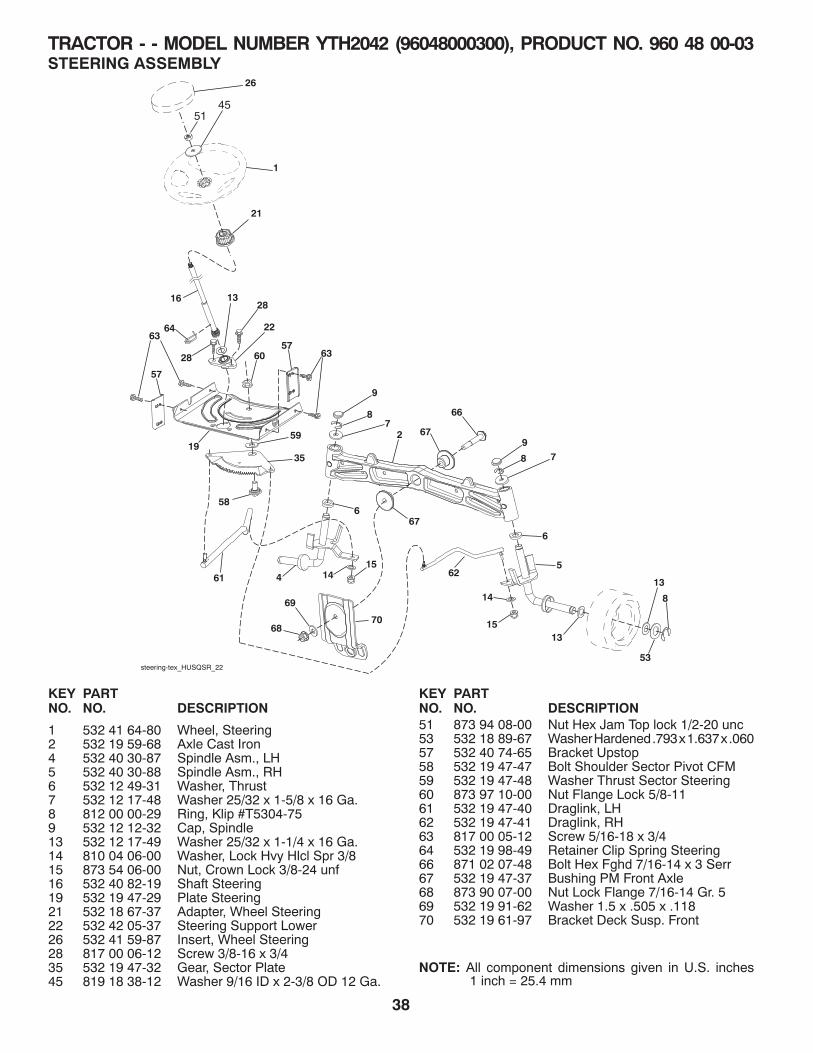
TRACTOR - - MODEL NUMBER YTH2042 (96048000300), PRODUCT NO. 960 48 00-03STEERING ASSEMBLY
KEY PARTNO. NO. DESCRIPTION
KEY PARTNO. NO. DESCRIPTION
1 532 41 64-80 Wheel, Steering2 532 19 59-68 Axle Cast Iron 4 532 40 30-87 Spindle Asm., LH5 532 40 30-88 Spindle Asm., RH6 532 12 49-31 Washer, Thrust7 532 12 17-48 Washer 25/32 x 1-5/8 x 16 Ga.8 812 00 00-29 Ring, Klip #T5304-759 532 12 12-32 Cap, Spindle13 532 12 17-49 Washer 25/32 x 1-1/4 x 16 Ga.14 810 04 06-00 Washer, Lock Hvy Hlcl Spr 3/815 873 54 06-00 Nut, Crown Lock 3/8-24 unf16 532 40 82-19 Shaft Steering19 532 19 47-29 Plate Steering21 532 18 67-37 Adapter, Wheel Steering22 532 42 05-37 Steering Support Lower26 532 41 59-87 Insert, Wheel Steering28 817 00 06-12 Screw 3/8-16 x 3/435 532 19 47-32 Gear, Sector Plate45 819 18 38-12 Washer 9/16 ID x 2-3/8 OD 12 Ga.
51 873 94 08-00 Nut Hex Jam Top lock 1/2-20 unc53 532 18 89-67 Washer Hardened .793 x 1.637 x .06057 532 40 74-65 Bracket Upstop58 532 19 47-47 Bolt Shoulder Sector Pivot CFM59 532 19 47-48 Washer Thrust Sector Steering60 873 97 10-00 Nut Flange Lock 5/8-1161 532 19 47-40 Draglink, LH62 532 19 47-41 Draglink, RH63 817 00 05-12 Screw 5/16-18 x 3/464 532 19 98-49 Retainer Clip Spring Steering66 871 02 07-48 Bolt Hex Fghd 7/16-14 x 3 Serr67 532 19 47-37 Bushing PM Front Axle68 873 90 07-00 Nut Lock Flange 7/16-14 Gr. 569 532 19 91-62 Washer 1.5 x .505 x .11870 532 19 61-97 Bracket Deck Susp. Front
NOTE: All component dimensions given in U.S. inches1 inch = 25.4 mm
62
3519
60
59
7068
69
15
14
61
steering-tex_HUSQSR_22
16
28
2813
2264
21
415
14
1
26
58
5
13
13
53
8
67
67
66
6
6
2
9
87
9
8 7
6357
57
63
5145

39
TRACTOR - - MODEL NUMBER YTH2042 (96048000300), PRODUCT NO. 960 48 00-03SEAT ASSEMBLY
1 532 42 40-68 Seat2 532 18 01-66 Bracket Pivot Fender3 532 14 06-75 Strap, Asm Fender6 873 80 06-00 Nut, Lock w/Ins. 3/8-16 unc7 532 12 41-81 Spring, Seat Cprsn8 532 17 18-77 Bolt 5/16-18 unc x 3/4 w/Sems10 532 19 69-77 Pan, Seat21 532 17 18-52 Bolt, Shoulder 5/16-18
37 873 80 05-00 Nut, Lock 5/16-18 unc40 532 19 76-61 Handle Slide Seat41 532 19 82-00 Spring Latch Seat43 874 76 06-12 Bolt Fin Hex 3/8-16 unc x 3/444 819 13 38-12 Washer 13/32 x 2-3/8 x 12 Ga.
KEY PARTNO. NO. DESCRIPTION
KEY PARTNO. NO. DESCRIPTION
NOTE: All component dimensions given in U.S. inches 1 inch = 25.4 mm
2
6
1
40
10
37
37
21
21
3
41
7
8
7
8
seat-tex_6.5SL_3
44
43
8
8
6

40
TRACTOR - - MODEL NUMBER YTH2042 (96048000300), PRODUCT NO. 960 48 00-03MOWER LIFT
7
3
87
10
88
2
89
90 98
97
97
lift-tex_17_r3 *Key 91 may be substituted for Key 101
91
101*
87
100
89
89
87
2 532 42 20-27 Shaft Asm., Lift 3 532 19 52-31 Lever Asm., Lift RH7 532 41 15-55 Grip, Lever10 532 19 63-14 Spring Torsion87 532 19 42-09 Pin Cotter 7/16 Bow Tie Lock88 532 41 07-10 Spring Lift Assist89 819 19 19-12 Washer Clear Zinc90 532 19 42-08 Pin Cotter 5/16 Bow Tie Lock91 532 19 51-81 Link Lift Susp Mower Rear
KEY PART NO. NO. DESCRIPTION
NOTE: All component dimensions given in U.S. inches 1 inch = 25.4 mm
97 817 00 06-12 Screw 3/8-16 x .75 Smgml Tap/R.Z98 532 19 52-70 Link Lift Susp. Front Mower100 873 93 06-00 Nut Center Lock 3/8-16 unc101 532 40 70-03 Link Asm Lift Fixed
KEY PART NO. NO. DESCRIPTION

41
TRACTOR - - MODEL NUMBER YTH2042 (96048000300), PRODUCT NO. 960 48 00-03DECALS
NOTE: All component dimensions given in U.S. inches 1 inch = 25.4 mm
KEY PART NO. NO. DESCRIPTION
6
2
1
311
410
59
8
7
wheel_art_1-tex
WHEELS AND TIRES
KEY PART NO. NO. DESCRIPTION
KEY PART NO. NO. DESCRIPTION
1 532 05 91-92 Cap Valve Tire 2 532 06 51-39 Stem Valve 3 532 13 83-36 Rim Front4 532 05 99-04 Tube Front (Service Item Only) 5 532 10 62-22 Tire Front 15 x 6.0-66 532 12 49-57 Fitting Grease (Front Wheel Only) 7 532 12 49-59 Bearing Flange (Front Wheel Only) 8 532 17 50-39 Cap Axle Blk 1 50 x 1 009 532 13 84-68 Tire R TS 20 x 8-8 C10 532 12 49-26 Tube Rear (Service Item Only) 11 532 13 83-37 Rim Asm 8" Rear- - 532 14 43-34 Sealant, Tire (10 oz. Tube)
1 532 41 16-58 Decal, Fender Warning2 532 42 91-96 Decal, Hood 3 532 43 86-65 Decal, Hood Panel SD4 532 17 05-63 Decal, Mower Warning5 532 42 38-29 Decal, Customer Respons.6 532 43 88-12 Decal, Replacement7 532 42 95-61 Decal, Engine H.P.
9 532 14 50-05 Decal, Battery Dnge/Poi12 532 16 03-96 Decal, Mower V-Belt Schematic- - 532 16 69-60 Decal, Bypass- - 532 41 08-05 Pad, Footrest, LH- - 532 41 08-06 Pad, Footrest, RH- - 532 44 05-64 Manual, Owner's (English)- - 532 44 05-65 Manual, Owner's (French)
9
4
12
2 5 6
3
2
1
7

42
SERVICE NOTES

43
15 DE
GR
EE
S M
AX
.
FOLD
ALO
NG
DO
TTED
LINE
THIS
IS A
15 DE
GR
EE
SLO
PE
ON
LY
RID
E U
P A
ND
DO
WN
HIL
L,
NO
T A
CR
OS
S H
ILL
SU
GG
ES
TE
D G
UID
E F
OR
SIG
HT
ING
SL
OP
ES
FO
R S
AF
E O
PE
RA
TIO
N
WA
RN
ING
: To
avoid
seriou
s inju
ry, op
erate you
r tractor u
p an
d
do
wn
the face o
f slop
es, never acro
ss the face. D
o n
ot m
ow
slop
es greater th
an 15 d
egrees. M
ake turn
s grad
ually to
preven
ttip
pin
g o
r loss o
f con
trol. E
xercise extreme cau
tion
wh
ench
ang
ing
directio
n o
n slo
pes.
1. Fo
ld th
is pag
e alon
g d
otted
line in
dicated
abo
ve.2. H
old
pag
e befo
re you
so th
at its left edg
e is vertically parallel to
a tree tru
nk o
r oth
er up
righ
t structu
re.3. S
igh
t across th
e fold
in th
e directio
n o
f hill slo
pe yo
u w
ant to
measu
re.4. C
om
pare th
e ang
le of th
e fold
with
the slo
pe o
f the h
ill.

12.15.10 JA Printed in the U.S.A.